catalogue 2017/2018 - tornbosvejs · rab grip 15 ak / 24 kd / 25 ak / 36 kd / 240 d / 501 / 501 d...
TRANSCRIPT

T E C H N O L O G Y F O R T H E W E L D E R ’ S W O R L D .
www.binzel -abicor.com
Catalogue 2017/2018MIG/MAG • Flux • TIG • Plasma • Electrode holders/Gouging torches • Accessories
AB
ICO
R B
INZ
EL •
Ca
talo
gu
e 2
01
7 /
20
18

32
Ladies and gentlemen!
On behalf of the ABICOR Group I welcome you warmly as existing or as well as potential users of our products and present to you herewith the new catalogue.
The years 2017/18 will have in our focus the introduction of our new MIG/MAG torch lines “MB EVO PRO“ and “ABIMIG® A & W“.
After more than 10 years of “MB Grip” there was the time to subject the MB line to a “facelift” and a technical advancement. As the result was created “MB EVO PRO”, another milestone in the field of our MIG/MAG welding torches. The air-cooled industrial torches, besides a new ergonomically conceptualized handle in 2-component technology, are fitted with the super lightweight BIKOX® LW, which has already made a splash being used in the lines ABIMIG® A and ABIMIG® A T.The liquid-cooled torches were revised at the cooling side and thanks to an optimized design possess a power reserve up to 10% compared to previous designs!
ABIMIG® A and ABIMIG® W with fix swan neck continue the success story of the already proven ABIMIG® A T and ABIMIG® W T series, more robust and powerful – the tool for really severe conditions.
The latest development in the field of TIG represents our new cold wire feeder “ABIDRIVE V2“ and also in the field of welding accessories you can expect some surprises, such as our new spatter protection fluid “ABIBLUE”. Be curious and test our products through their paces, we are anxious to hear your opinion!
I wish you much joy and success in work with our products and look forward to many years of good cooperation.
Faithfully yours
Jens SchleicherDirector of Sales & MarketingABICOR Group

54
Content FCAW Welding Torches / TIG Welding TorchesMIG/MAG Welding Torches
MIG/MAG Welding Torches■ MIG/MAG Welding Torches “ABIMIG® A T LW” liquid cooled (up to 240 A) Page 10–11
ABIMIG® A T 155 LW / 255 LW
■ MIG/MAG Welding Torches “ABIMIG® A T LW” air cooled (up to 400 A) Page 12–13ABIMIG® A T 305 LW / 355 LW / 405 LW
■ MIG/MAG Welding Torches “ABIMIG® A T LW” Page 14Flexible changeable torch necks
■ MIG / MAG Gas nozzles and contact tips Page 15Gas nozzles for narrow gap welding for ABIMIG® A
■ MIG/MAG Welding Torches “ABIMIG® A LW” air cooled (up to 230 A) Page 16–17ABIMIG® A 155 LW / 255 LW
■ MIG/MAG Welding Torches “ABIMIG® A LW” air cooled (up to 400 A) Page 18–19
ABIMIG® A 305 LW / 355 LW / 405 LW
■ MIG/MAG Welding Torches “ABIMIG® W T” liquid cooled (up to 600 A) Page 20–21
■
ABIMIG® W T 340 / 440 / 540
MIG/MAG Welding Torches “ABIMIG® W” liquid cooled (up to 600 A)ABIMIG® W 340 / 440 / 540
Page 22–23
■ MIG / MAG Gas nozzles and contact tips Page 24Gas nozzles for narrow gap welding for ABIMIG® W
■ MIG/MAG Welding Torches “MB EVO PRO” air cooled (up to 230 A) Page 26–27MB EVO PRO 15, MB EVO PRO 25
■ MIG/MAG Welding Torches “MB EVO PRO” air cooled (up to 320 A) Page 28–29MB EVO PRO 24, MB EVO PRO 26, MB EVO PRO 36
■ MIG/MAG Welding Torches “MB EVO PRO” liquid cooled (up to 575 A) Page 30–31MB EVO PRO 240, MB EVO PRO 401, MB EVO PRO 501
■ MIG/MAG Welding Torches “MB EVO” air cooled (up to 230 A) Page 32–33MB EVO 15, MB EVO 25
■ MIG/MAG Welding Torches “MB EVO” air cooled (up to 320 A) Page 34–35MB EVO 24, MB EVO 26, MB EVO 36
■ MIG/MAG Welding Torches “MB EV” liquid cooled (up to 550 A) Page 36–37
■
■
■
■
MB EVO 240, MB EVO 401, MB EVO 501
MIG/MAG Welding Torches “ABIMIG® GRIP W” liquid cooled (up to 575 A)ABIMIG® GRIP W 555 D / 555 D TS / 555
MIG/MAG Welding Torches “ABIMIG® GRIP W” liquid cooled (up to 625 A)ABIMIG® GRIP W 605 / 605 D / 605 C
MIG/MAG Welding Torches “Push-Pull Plus” air and liquid cooled (up to 350 A)PP Plus 36 D / 240 D / 401 D
MIG/MAG Fume Extraction Torches “RAB GRIP” air and liquid cooled (up to 550 A)RAB GRIP 15 AK / 24 KD / 25 AK / 36 KD / 240 D / 501 / 501 D
Page 38–39
Page 40–41
Page
Page
42–43
44–45
■ Fume Extraction System Page 46–47 FES-200 / FES-200 W3
■ MIG/MAG Machine Welding Torches air and liquid cooled Page 48–49 AUT / ABIMIG® MT
■ MIG/MAG Gas nozzles and contact tips Page 50 Bent gas nozzles and contact tips for MB 15 / 24 / 26 and MB 240 / 401 / 501
Spare Parts■ Bikox®, Control Cables, Hoses and Liners Page 52–53
■ Handles and control modulesABIMIG® A T / W T /A / W, EVO PRO / EVO, RAB GRIP, ABIMIG® GRIP
Page 54–59
■ Central adaptor and central connector system Page 60–63
MIG
/MA
G T
IG F
CAW
TIG Welding Torches■ TIG Welding Torches “ABITIG® GRIP” air and liquid cooled Page 70–71 ABITIG® GRIP 9 / ABITIG® GRIP 20
■ TIG Welding Torches “ABITIG® GRIP” air and liquid cooled Page 72–73 ABITIG® GRIP 17 / ABITIG® GRIP 18 / ABITIG® GRIP 26
■ TIG Welding Torches “ABITIG® GRIP” air and liquid cooled Page 74–75 ABITIG® GRIP 24 G / ABITIG® GRIP 24 W
■ TIG Welding Torches “ABITIG® GRIP” liquid cooled Page 76–77 ABITIG® GRIP 12-1
■ TIG Welding Torches “ABITIG® GRIP” liquid cooled Page 78–79 ABITIG® GRIP 18 SC
■ TIG Welding Torches “ABITIG®” air cooled with rotary valve Page 80–83 ABITIG® 9 V and FV / ABITIG® 17 V and FV / ABITIG® 26 V and FV
■ TIG Welding Torches “ABITIG® GRIP Little” air and liquid cooled Page 84–85 ABITIG® GRIP Little 90 / 180 W
■ TIG Welding Torches “ABITIG® GRIP” liquid cooled Page 86–87 ABITIG® GRIP 150 / ABITIG® GRIP 260 W
■ TIG Welding Torches “ABITIG® GRIP” air and liquid cooled Page 88–89 ABITIG® GRIP 200 / ABITIG® GRIP 450 W / ABITIG® GRIP 450 W SC
■ TIG Welding Torches “ABITIG® GRIP” liquid cooled Page 90–91 ABITIG® GRIP 500 W
■ TIG Welding Torches “ABITIG® GRIP Little” air and liquid cooled Page 92–93 ABITIG® GRIP Little 9 / 9 F / 20 / 20 F ABITIG® GRIP Little 17 / 24 G / 24 W ABITIG® GRIP Little 90 / 150 / 150 F / 260 W / 180 W
■ TIG Machine Torches air and liquid cooled Page 94–99 ABITIG® 150 MT / ABITIG® 260 W MT / ABITIG® 200 MT / ABITIG® 300 W MT / ABITIG® 400 W MT / ABITIG® 500 W MT
FCAW Welding Torches ALPHA FLUX■ FCAW Welding Torches air cooled Page 66–67 Rating to 330 A

76
Plasma Cutting Torches ■ Plasma Cutting Torches “ABIPLAS® CUT” air cooled Page 114–115
ABIPLAS® CUT 70 / ABIPLAS® CUT 70 MT
■ Plasma Cutting Torches “ABIPLAS® CUT” air cooled Page 116–117ABIPLAS® CUT 110 / ABIPLAS® CUT 110 MT
■ Plasma Cutting Torches “ABIPLAS® CUT” air cooled Page 118–119ABIPLAS® CUT 150 / ABIPLAS® CUT 150 MT
■ Plasma Cutting Torches “ABIPLAS® CUT” liquid cooled Page 120–121 ABIPLAS® CUT 200 W / ABIPLAS® CUT 200 W MT
■ Plasma Cutting Torches “ABICUT” air cooled Page 122–123ABICUT 25K / ABICUT 45
■ Plasma Cutting Torches “ABICUT” air cooled Page 124–125ABICUT 75
■ Plasma Cutting Torches “PSB” air cooled Page 126–127 ABIPLAS® CUT 100 W / MT, ABIPLAS® CUT 150 W MT
Spare Parts ■ Cable assembly components and Cable assemblies, Hoses, Handles and so on … Page 128–130
Electrode holders / Gouging torches / Accessories
PLA
SMA
EH
/FH
ACC
ESSO
RIE
S
Accessories■ Tungsten electrodes Page 100–101
■ Cold Wire Feeder System Page 102–103 “ABIDRIVE-V2”
■ TIG Welding Torches “ABITIG®” and “ABITIG®-MT” liquid cooled with cold wire feeding
Page 104–105
ABITIG® 260 W / ABITIG® 450 W / ABITIG® 260 W MT / ABITIG® 300 W MT / ABITIG® 400 W MT / ABITIG® 500 W MT
Component Kits■ ABITIG® 9 / 12-1 / 17 / 18 / 18 SC / 20 / 24 G / 24 W / 26
ABITIG® 150 / 200 / 260 W / 450 W / 450 W SC Page 106–107
Spare Parts■ Power cables, Control cables, Hoses Page 108–109■ Handles and Modules Page 110–111
Content TIG Welding Torches / Plasma Torches
Electrode holders■ DE 2200 / DE 2300 / DE 2400 / DE 2500 Page 134–135
Gouging torches■ K10 / K 12 / / K12T / K16T / K20 Page 136–137
■ Gouging electrodes TEAM BINZEL® Page 138–139 ABIARC / ABIARC AL
Accessories■ Welding chemicals Page 142–144 Anti-spatter and coolant liquids
■ Torch function tester Page 145 BFP001
■ Welding cable connector system Page 146–147 ABIPLUG
■ TIG Welding Torches “ABITIG® GRIP” liquid cooled Page 86–87 ABITIG® GRIP 150 / ABITIG® GRIP 260 W
■ Welding accessories Page 148–149 Adapter pieces, double nipple and quick couplings
■ Cooling units CR 1000 & CR 1250 Page 150–151 Light-weight and user-friendly
■ Installation of the integrated flow switch Page 152 Simple and fast
■ Automatic welding helmet Page 153 Surely and reliable
■ Gas pressure regulators Page 154 KAYSER Germany

MIG
/MA
G
98
MIG/MAG Welding Torches
MIG/MAG Welding Torches ■ ABIMIG® A T 155 LW / 255 LW
■ ABIMIG® A T 305 LW / 355 LW / 405 LW
■ Flexible changeable torch necks
■ Gas nozzles for narrow gap welding
■ ABIMIG® A 155 LW / 255 LW
■ ABIMIG® A 305 LW / 355 LW / 405 LW
■ ABIMIG® W T 340 / W T 440 / W T 540
■ ABIMIG® W 340 / W 440 / W 540
■ Gas nozzles for narrow gap welding
■ MB EVO PRO 15 / EVO PRO 25
■ MB EVO PRO 24 / EVO PRO 26 / EVO PRO 36
■ MB EVO PRO 240 / EVO PRO 401 / 501
■ MB EVO 15 / EVO 25
■ MB EVO 24 / EVO 26 / EVO 36
■ MB EVO 240 / EVO 401 / 501
■ ABIMIG® GRIP W 555 D / 555 / 555 D TS
■ ABIMIG® GRIP W 605 / 605 D / 605 C
■ PP Plus 36 / 240 / 401
■ RAB GRIP 15 AK / 24 KD / 25 AK / 36 KD / 240 D / 501 / 501 D
■ RAB GRIP
■ FES-200 / FES-200 W3
■ AUT / ABIMIG® MT
Spare Parts ■ Bent gas nozzles, Bikox®, Control Cables, Hoses, Handles, Modules and Liners
Central adaptor /central connector system ■ The universal connection …
Central adaptor with spring contacts ■ Flexible contact …

MIG
/MA
G
1110
Ø 22Ø BØ A Ø 20
Ø 6
25 mm
Ø 8
28 mm
M6
35 mm
M6
51 mm
Gas nozzle (5 pcs.) Ø A X1 Ø B X2 Cylindrical Ø 17 52 mm 145.D003 Ø 18 69 mm 145.D014Conical Ø 12 52 mm 145.D001 Ø 16 70 mm 145.D011Conical Ø 12 54 mm 145.D004 Ø 14 67 mm 145.D012
X2X1
MIG/MAG Welding Torches “ABIMIG® A T LW”Air cooled • rating 180 A up to 240 A
The newly developed, super lightweight MIG/MAG welding torch series “ABIMIG® A T LW” with ergo-nomic and universal two-component handle offer flexibility in perfection. They are equipped standard with ball joint and lightweight “Bikox® LW” cable assembly as well as exchangeable and 360° rota-table torch neck, so the torches enable ergonomic and relaxed welding in every position.
■ New welding torch series and lightweight “Bikox® LW” cable assembly – Reduction of the torch weight up to 50 %
■ Newly designed ergonomic handle, optionally available with Up/Down module – Improved working comfort
■ Universal contact tip holder (contact tip holder, gas diffuser and gas nozzle holder all in one) – Reduction of the number of spare parts and thus the costs
■ Screwable, thermally insulated gas nozzle – Longer service life of the torch and cost reduction
■ Turnable, quick-change torch neck – increased working comfort and reduction of service costs
ABIMIG® A T 155 LWTechnical data (EN 60 974-7):Rating: 190 A CO2
180 A Mixed Gases M21 (DIN EN 439)
Duty cycle: 60 %Wire size: 0.8–1.0 mm
ABIMIG® A T 255 LWTechnical data (EN 60 974-7):Rating: 240 A CO2
220 A Mixed Gases M21 (DIN EN 439)
Duty cycle: 60 %Wire size: 0.8–1.2 mm
Torch complete Part-No. Swan neckType Handle 3 m 4 m 5 m Type Part-No.ABIMIG® A T 155 LW Trigger long 006.D810.1 006.D811.1 006.D812.1 45° 006.D804.1ABIMIG® A T 255 LW Trigger long 004.D850.1 004.D851.1 004.D852.1 45° 004.D831.1
Definition: T = turnable/exchangeable torch neck, LW = lightweight cable assemblyAttention: The specified variants correspond to the “BASIC” version. Further versions (COMBI, VARIO, FREE STYLE) on request.
ABIMIG® A T 155 LW, ABIMIG® A T 255 LW
ABIMIG® A T 155 LW ABIMIG® A T 255 LWWear parts
Contact tip (10 pcs.) M6 M6E-Cu Ø 0.8 140.0059 140.0051
Ø 1.0 140.0253 140.0242Ø 1.2 – 140.0379
E-Cu for Al Ø 0.8 141.0002 141.0001Ø 1.0 141.0007 141.0006Ø 1.2 – 141.0010
CuCrZr Ø 0.8 140.0062 140.0054Ø 1.0 140.0256 140.0245Ø 1.2 – 140.0382
Contact tip holder (5 pcs.)006.D719.5 004.D624.5
Torch neck liner for T-torchesStandard Ø 0.8 122.D037 122.D037
Ø 1.0 122.D038 122.D038Ø 1.2 – 122.D038
Brass for Al Ø 0.8 122.D040 122.D040Ø 1.0 122.D040 122.D041Ø 1.2 – 122.D041
Liner for 3 m for 4 m for 5 mLiner Ø 0.8 124.0011 124.0012 124.0015
Ø 1.0 124.0026 124.0031 124.0035Ø 1.2 124.0026 124.0031 124.0035
PTFE liner Ø 0.8 126.0005 126.0008 126.0011Ø 1.0 126.0021 126.0026 126.0028Ø 1.2 126.0021 126.0026 126.0028
Carbon PTFE liner
Ø 0.8 127.0002 127.0003 127.0004Ø 1.0 127.0005 127.0007 127.0008Ø 1.2 127.0005 127.0007 127.0008
Spacer (5 pcs.)767.D607.5 767.D637.5

MIG
/MA
G
1312
Ø A Ø 25 Ø A Ø 25
X1 X1
Ø 10
30 mm
Ø 10
30 mm
M8
52 mm
M8
52 mm
MIG/MAG Welding Torches “ABIMIG® A T LW” Air cooled • rating 260 A up to 400 A
ABIMIG® A T 305 LWTechnical data (EN 60 974-7):Rating: 290 A CO2
260 A Mixed Gases M21 (DIN EN 439)
Duty cycle: 60 %Wire size: 0.8–1.2 mm
ABIMIG® A T 355 LWTechnical data (EN 60 974-7):Rating: 340 A CO2
320 A Mixed Gases M21 (DIN EN 439)
Duty cycle: 60 %Wire size: 1.0–1.6 mm
ABIMIG® A T 405 LW*
Technical data (EN 60 974-7):Rating: 400 A CO2
370 A Mixed Gases M21 (DIN EN 439)
Duty cycle: 60 %Wire size: 1.0–1.6 mm
(up to 2.4 mm on demand)
■ New welding torch series and lightweight “Bikox® LW” cable assembly – Up to 50 % lighter than comparable standard torches
■ Newly designed ergonomic torch handle, available with optional Up/Down module – Improved working comfort
■ Universal contact tip holder (contact tip holder, gas diffuser and gas nozzle holder all in one) – Reduces stocking requirements and costs
■ Screwable, thermally insulated gas nozzle – Longer service life of the torch – Cost reduction
■ Turnable, quick-change torch neck – increased working comfort and reduction of service costs
Torch complete Part-No. Swan neckType Handle 3 m 4 m 5 m Type Part-No.ABIMIG® A T 305 LW Trigger long 018.D960.1 018.D961.1 018.D962.1 45° 014.H356.1ABIMIG® A T 355 LW Trigger long 014.H390.1 014.H391.1 014.H392.1 45° 014.H363.1ABIMIG® A T 405 LW Trigger long 015.D070.1 015.D071.1 015.D072.1 45° 015.D082.1
Definition: T = turnable/exchangeable torch neck, LW = lightweight cable assemblyAttention: The specified variants correspond to the “BASIC” version. Further versions (COMBI, VARIO, FREE STYLE) on request.
*The ABIMIG® A T 405 LW is adjustable in 45° steps.
ABIMIG® A T 305 LW, ABIMIG® A T 355 LW, ABIMIG® A T 405 LW
ABIMIG® A T 305 / 355 LWWear parts
Gas nozzle (5 pcs.) Ø A X1 Ø A X1 Cylindrical Ø 21 71 mm 145.D024 Ø 21 71 mm 145.D024Conical Ø 18 72 mm 145.D021 Ø 18 72 mm 145.D021Conical Ø 16 69 mm 145.D022 Ø 16 69 mm 145.D022
Contact tip (10 pcs.) M8 M8E-Cu Ø 0.8 140.0114 140.0114
Ø 1.0 140.0313 140.0313Ø 1.2 140.0442 140.0442Ø 1.6 140.0587 140.0587
E-Cu for Al Ø 0.8 141.0003 141.0003Ø 1.0 141.0008 141.0008Ø 1.2 141.0015 141.0015Ø 1.6 141.0022 141.0022
CuCrZr Ø 0.8 140.0117 140.0117Ø 1.0 140.0316 140.0316Ø 1.2 140.0445 140.0445Ø 1.6 140.0590 140.0590
Contact tip holder (5 pcs.) M8 014.D745.5 014.D745.5
Torch neck liner for T-torches Standard Ø 0.8 122.D037 –
Ø 1.0–1.2 122.D038 122.D077Ø 1.6 122.D045 122.D078
Brass for Al Ø 1.0 122.D040 122.D040Ø 1.0–1.2 122.D041 122.D041
ABIMIG® A T 405 LW
305 / 355 405 305 / 355 405 305 / 355 405Liner for 3 m for 3 m for 4 m for 4 m for 5 m for 5 mLiner 0.8 124.0011 – 124.0012 – 124.0015 –
1.0 124.0026 124.D113 124.0031 124.D114 124.0035 124.D1151.2 124.0026 124.D116 124.0031 124.D117 124.0035 124.D1181.6 124.0041 124.D119 124.0042 124.D120 124.0044 124.D121
PTFE liner 0.8 126.0005 – 126.0008 – 126.0011 –1.0 126.0021 – 126.0026 – 126.0028 –1.2 126.0021 – 126.0026 – 126.0028 –1.6 126.0039 – 126.0042 – 126.0045 –
Carbon PTFE liner
0.8 127.0002 – 127.0003 – 127.0004 –1.0 127.0005 – 127.0007 – 127.0008 –1.2 127.0005 – 127.0007 – 127.0008 –1.6 127.0010 – 127.0012 – 127.0013 –
Spacer (5 pcs.)767.D668.5 015.D080.5
Note: Combined wire guides for ABIMIG® A / A T 405 LW on page 33.

MIG
/MA
G
1514
MIG/MAG Welding Torches “ABIMIG® A T LW” Flexible changeable torch necks
Compatible for torch line ABIMIG® T and ABIMIG® A T with torch neck interface (M22 x 1.5).
FLEX copl. For contact tip X006.0133.1 COMBI-Neck A T 155 T8 M6 230004.0646.1 COMBI-Neck A T 255 T8 M6 250018.0191.1 COMBI-Neck A T 305 T8 M8 250
FLEX copl. For contact tip X f S1 S2018.0198.1 COMBI-Neck A T 305 T8 M8 350 108 96 146018.0199.1 COMBI-Neck A T 305 T8 M8 500 180 96 296
Flexible special torch necks:The flexible special torch necks combine an inflexible straight torch neck and a flexible front end.
X
X
inflexible part S2
flexible part finflexible part S1
MIG/MAG Gas nozzles and Contact tipsGas nozzles for narrow gap welding
For all torches ABIMIG® 155 … 405
■ Compatible for standard tip holders ■ Special gas nozzles and contact tips are
necessary ■ All Gas nozzles are nickel plated. ■ The contact tip material is CuCrZr.
Attention: ■ The amperage rates are reduced based on the
small gap welding conditions and the small tube walls of the gas nozzles.
■ Because of the small gap between the gas nozzle and the contact tip a regular cleaning is a protec-tion against short circuit.
For ABIMIG® 155Gas nozzle BOT M12 DN9 L98 145.D450.5Contact tip CuCrZr M6/0.8/71 140.1644.10Contact tip CuCrZr M6/0.8/71 140.D465.10
For ABIMIG® 255Gas nozzle BOT M14 DN9 L112 145.D448.5Contact tip CuCrZr M6/0.8/71 140.1644.10Contact tip CuCrZr M6/1.0/71 140.D465.10Contact tip CuCrZr M6/1.2/71 140.D466.10
For ABIMIG® 305/355/405Gas nozzle BOT M16 DN13 L126 145.D437.5Contact tip CuCrZr M8/1.0/85 140.1584.10Contact tip CuCrZr M8/1.2/85 140.1585.10

MIG
/MA
G
1716
Ø 22Ø BØ A Ø 20
Ø 6
25 mm
Ø 8
28 mm
M6
35 mm
M6
51 mm
Gas nozzle (5 pcs.) Ø A X1 Ø B X2 Cylindrical Ø 17 52 mm 145.D003 Ø 18 69 mm 145.D014Conical Ø 12 52 mm 145.D001 Ø 16 70 mm 145.D011Conical Ø 12 54 mm 145.D004 Ø 14 67 mm 145.D012
X2X1
ABIMIG® A 155 LW, ABIMIG® A 255 LW
ABIMIG® A 155 LW ABIMIG® A 255 LWWear parts
Contact tip (10 pcs.) M6 M6E-Cu Ø 0.8 140.0059 140.0051
Ø 1.0 140.0253 140.0242Ø 1.2 – 140.0379
E-Cu for Al Ø 0.8 141.0002 141.0001Ø 1.0 141.0007 141.0006Ø 1.2 – 141.0010
CuCrZr Ø 0.8 140.0062 140.0054Ø 1.0 140.0256 140.0245Ø 1.2 – 140.0382
Contact tip holder (5 pcs.)006.D719.5 004.D624.5
Liner for 3 m for 4 m for 5 mLiner Ø 0.8 124.0011 124.0012 124.0015
Ø 1.0 124.0026 124.0031 124.0035Ø 1.2 124.0026 124.0031 124.0035
PTFE liner Ø 0.8 126.0005 126.0008 126.0011Ø 1.0 126.0021 126.0026 126.0028Ø 1.2 126.0021 126.0026 126.0028
Carbon PTFE liner
Ø 0.8 127.0002 127.0003 127.0004Ø 1.0 127.0005 127.0007 127.0008Ø 1.2 127.0005 127.0007 127.0008
Spacer (5 pcs.)767.D607.5 767.D637.5
MIG/MAG Welding Torches “ABIMIG® A LW”Air cooled • rating 170 A up to 230 A
MIG/MAG welding torches ABIMIG® A LW with fixed torch neck open a new chapter in the development of the successful ABIMIG® line. Optimized production technologies and materials enabled the increase of product strengths, especially for use in the most severe environment. So, tasks with averages up to 350 A can be trouble-free welded air-cooled. The proven ABIMIG® parts show also in this power range secure both gas coverage and durability.
The torches of the ABIMIG® A LW series utilize the Low Weight Bikox®, which gives perfect balance to the torches for effortless welding in all positions. All torches are carefully designed to provide comfortable and precise operation.
■ Low Weight Bikox® – up to 50 % weight saving ■ Screw-on gas nozzle with thermo-protective
insulation – extending torch life ■ Function integrated tip holder (gas diffuser, gas
nozzle holder and contact tip holder in one piece) – reduces stock requirements
■ Laminar gas feed – excellent gas coverage for best welding results
■ Changeable gas nozzle seat – “extends” operating cycle of the torch neck and reduces maintenance costs
■ Electrically insulated liner and connection nut (on the central adaptor) – enables exact setting of the arc parameters and therefore repeatability of welding results
ABIMIG® A 155 LWTechnical data (EN 60 974-7):Rating: 170 A CO2
170 A Mixed Gases M21 (DIN EN 439)
Duty cycle: 60 %Wire size: 0.6–1.0 mm
ABIMIG® A 255 LWTechnical data (EN 60 974-7):Rating: 230 A CO2
220 A Mixed Gases M21 (DIN EN 439)
Duty cycle: 60 %Wire size: 0.8–1.2 mm
Torch complete Part-No. Swan neckType Handle 3 m 4 m 5 m Type Part-No.ABIMIG® A 155 LW Trigger short 767.0030.1 767.0031.1 767.0032.1 45° 767.0024.1ABIMIG® A 155 LW Trigger long 767.0062.1 767.0063.1 767.0064.1 45° 767.0024.1ABIMIG® A 255 LW Trigger short 767.0033.1 767.0034.1 767.0035.1 45° 767.0027.1ABIMIG® A 255 LW Trigger long 767.0065.1 767.0066.1 767.0067.1 45° 767.0027.1

MIG
/MA
G
1918
MIG/MAG Welding Torches “ABIMIG® A LW” Air cooled • rating 255 A up to 400 A
ABIMIG® A 305 LWTechnical data (EN 60 974-7):Rating: 280 A CO2
260 A Mixed Gases M21 (DIN EN 439)
Duty cycle: 60 %Wire size: 0.8–1.2 mm
ABIMIG® A 355 LWTechnical data (EN 60 974-7):Rating: 330 A CO2
310 A Mixed Gases M21 (DIN EN 439)
Duty cycle: 60 %Wire size: 1.0–1.6 mm
ABIMIG® A 405 LW*
Technical data (EN 60 974-7):Rating: 400 A CO2
350 A Mixed Gases M21 (DIN EN 439)
Duty cycle: 60 %Wire size: 1.2–1.6 mm
(up to 2.4 mm on demand)
Torch complete Part-No. Swan neckType Handle 3 m 4 m 5 m Type Part-No.ABIMIG® A 305 LW Trigger short 767.0036.1 767.0037.1 767.0038.1 45° 767.0045.1ABIMIG® A 305 LW Trigger long 767.0068.1 767.0069.1 767.0070.1 45° 767.0045.1ABIMIG® A 355 LW Trigger short 767.0039.1 767.0040.1 767.0041.1 50° 767.0050.1ABIMIG® A 355 LW Trigger long 767.0071.1 767.0072.1 767.0073.1 50° 767.0050.1ABIMIG® A 405 LW Trigger short 767.0042.1 767.0043.1 767.0044.1 50° 767.0055.1ABIMIG® A 405 LW Trigger long 767.0074.1 767.0075.1 767.0076.1 50° 767.0055.1
Ø A Ø 25 Ø A Ø 25
X1 X1
Ø 10
30 mm
Ø 10
30 mm
M8
52 mm
M8
52 mm
ABIMIG® A 305 LW, ABIMIG® A 355 LW, ABIMIG® A 405 LW
ABIMIG® A 305 / 355 LWWear parts
Gas nozzle (5 pcs.) Ø A X1 Ø A X1 Cylindrical Ø 21 71 mm 145.D024 Ø 21 71 mm 145.D024Conical Ø 18 72 mm 145.D021 Ø 18 72 mm 145.D021Conical Ø 16 69 mm 145.D022 Ø 16 69 mm 145.D022
Contact tip (10 pcs.) M8 M8E-Cu Ø 0.8 140.0114 140.0114
Ø 1.0 140.0313 140.0313Ø 1.2 140.0442 140.0442Ø 1.6 140.0587 140.0587
E-Cu for Al Ø 0.8 141.0003 141.0003Ø 1.0 141.0008 141.0008Ø 1.2 141.0015 141.0015Ø 1.6 141.0022 141.0022
CuCrZr Ø 0.8 140.0117 140.0117Ø 1.0 140.0316 140.0316Ø 1.2 140.0445 140.0445Ø 1.6 140.0590 140.0590
Contact tip holder (5 pcs.) M8 014.D745.5 014.D745.5
ABIMIG® A 405 LW
305 / 355 405 305 / 355 405 305 / 355 405Liner for 3 m for 3 m for 4 m for 4 m for 5 m for 5 mLiner 0.8 124.0011 – 124.0012 – 124.0015 –
1.0 124.0026 124.D113 124.0031 124.D114 124.0035 124.D1151.2 124.0026 124.D116 124.0031 124.D117 124.0035 124.D1181.6 124.0041 124.D119 124.0042 124.D120 124.0044 124.D121
PTFE liner 0.8 126.0005 – 126.0008 – 126.0011 –1.0 126.0021 – 126.0026 – 126.0028 –1.2 126.0021 – 126.0026 – 126.0028 –1.6 126.0039 – 126.0042 – 126.0045 –
Carbon PTFE liner
0.8 127.0002 – 127.0003 – 127.0004 –1.0 127.0005 – 127.0007 – 127.0008 –1.2 127.0005 – 127.0007 – 127.0008 –1.6 127.0010 – 127.0012 – 127.0013 –
Spacer (5 pcs.)767.D668.5 015.D080.5
Note: Combined wire guides for ABIMIG® A / A T 405 LW on page 33.

MIG
/MA
G
2120
M6
X mm
M10x1 M8
X mm
M10x1
Ø A Ø 22
66 mm
Ø A Ø 24
66 mm
Ø A Ø 20
62 mm
Ø 10Ø 8
30 mm28 mm
Ø 10
30 mm
M8
X mm
M11x1
Wear parts ■ Long-life screw-in gas nozzles with integrated, exchangeable spatter protection
■ A single basic torch for three capacities – reduces storage and maintenance costs
■ Quick change, freely positionable torch necks – increase working comfort and reduce servicing costs
■ Torch necks available in many different lengths and bending angles – for best accessibility
■ Extended and short triggers available – for best handling
■ Tried-and-tested ergonomic grip – easy to hold in all positions
MIG/MAG Welding Torches “ABIMIG® W T”Liquid cooled • rating 350 A up to 600 A
ABIMIG® W T 340, ABIMIG® W T 440, ABIMIG® W T 540
Torch complete Part-No. Swan neckType Handle 3 m 4 m 5 m Type Part-No.ABIMIG® W T 340 Trigger short 788.0041.1 788.0042.1 788.0043.1 50° 788.0020.1ABIMIG® W T 340 Trigger long 788.0116.1 788.0117.1 788.0118.1 50° 788.0020.1ABIMIG® W T 440 Trigger short 788.0044.1 788.0045.1 788.0046.1 50° 788.0005.1ABIMIG® W T 440 Trigger long 788.0119.1 788.0120.1 788.0121.1 50° 788.0005.1ABIMIG® W T 540 Trigger short 788.0047.1 788.0048.1 788.0049.1 50° 788.0026.1ABIMIG® W T 540 Trigger long 788.0122.1 788.0123.1 788.0124.1 50° 788.0026.1
ABIMIG® W T 340 ABIMIG® W T 440
Gas nozzle incl. spat-ter protection2 (5 pcs.) Ø A Ø A Ø ACylindrical Ø 17 145.0740.5 Ø 18 145.0745.5 Ø 20 145.0742.5Conical Ø 12.5 145.0737.51 Ø 14.5 145.D092.51 Ø 16 145.0735.51
Conical Ø 10 145.0739.5 Ø 12 145.0746.5 Ø 14 145.0741.5Spatter protector 146.0081.10 146.D003.10 146.0080.10
Liner for 3 m for 4 m for 5 mSpiral Ø 0.8 124.0137 124.0138 124.0139
Ø 1.0 124.01111 124.01121 124.01131
Ø 1.2 124.01111 124.01121 124.01131
Ø 1.6 124.0114 124.0115 124.0116PTFE liner
Ø 0.8 126.0005 126.0008 126.0011Ø 1.0 126.0021 126.0026 126.0028Ø 1.2 126.0021 126.0026 126.0028Ø 1.6 126.0039 126.0042 126.0045
BPL liner Ø 0.8 126.0069 126.0070 126.0071Ø 1.0 126.0069 126.0070 126.0071Ø 1.2 126.0069 126.0070 126.0071Ø 1.6 126.0072 126.0073 126.0074
ABIMIG® W T 540
Note for liquid cooled torches:To protect cable assembly components from excessive heat build up we recommend a post welding cooling cycle of at least four minutes.
Contact tip (10 pcs.) M6 M8 M8E-Cu Ø 0.8 140.0051 140.0114 –
Ø 1.0 140.0242 140.0313 140.0313Ø 1.2 140.0379 140.0442 140.0442Ø 1.6 – 140.0587 140.0587
E-Cu for Al Ø 0.8 141.0001 141.0033 –Ø 1.0 141.0006 141.0008 141.0008Ø 1.2 141.0010 141.0015 141.0015Ø 1.6 – 141.0022 141.0022
CuCrZr Ø 0.8 140.0054 140.0117 –Ø 1.0 140.02451 140.0316 140.0316Ø 1.2 140.0382 140.04451 140.04451
Ø 1.6 – 140.0590 140.0590
Contact tip holder (5 pcs.) X X XBrass 24.0 142.0241.5 26.0 142.0252.5 25.0 142.0239.5
26.0 142.0242.51 28.0 142.0253.51 27.0 142.0240.51
– – 31.0 142.0243.5 – –CuCrZr – – – – 25.0 142.0247.5
– – – – 27.0 142.0248.5
Torch neck linerSpiral Ø 0.8–1.2 123.D0971 123.D0971 123.D0971
Ø 1.4–1.6 – 123.D098 123.D098BPL liner Ø 0.8–1.2 149.0418.1 149.0418.1 149.0418.1
Ø 1.4–1.6 149.0420.1 149.0420.1 149.0420.1
¹ Included in the standard equipment for complete torches. ² The integrated spatter protection is already contained in the above-mentioned gas nozzles and can be ordered separately on request.
Welding torches in the ABIMIG® W T series convince through higher load limits than traditional torches of the same size, because the cooling concept that was redesigned by ABICOR BINZEL protects wearing parts even better against overheating with high power consumption as well.
A spatter protector integrated in the gas nozzles makes them particularly resistant and can be replaced separately where required. In addition, the torch necks and the gas nozzle are nickel-plated, in order to reduce spatter adhesions to a minimum.
Thanks to the rotatable and exchangeable torch necks in various lengths and geometries welders can adjust the ABIMIG® W T torch exactly to their needs.
ABIMIG® W T 340Technical data (EN 60 974-7):Rating: 400 A CO2
350 A Mixed Gases M21 (DIN EN 439)
Duty cycle: 100 %Wire size: 0.8–1.2 mm
ABIMIG® W T 440Technical data (EN 60 974-7):Rating: 500 A CO2
450 A Mixed Gases M21 (DIN EN 439)
Duty cycle: 100 %Wire size: 0.8–1.6 mm
ABIMIG® W T 540*
Technical data (EN 60 974-7):Rating: 600 A CO2
550 A Mixed Gases M21 (DIN EN 439)
Duty cycle: 100 %Wire size: 1.0–1.6 mm

MIG
/MA
G
2322
■ Long-life screw-in gas nozzles with integrated, exchangeable spatter protection
■ Extended and short triggers available – for best handling
■ Tried-and-tested ergonomic grip – easy to hold in all positions
MIG/MAG Welding Torches “ABIMIG® W”Liquid cooled • rating 350 A up to 600 A
Torch complete Part-No. Swan neckType Handle 3 m 4 m 5 m Type Part-No.ABIMIG® W 340 Trigger short 766.1530.1 766.1531.1 766.1532.1 50° 766.1553.1ABIMIG® W 340 Trigger long 766.1558.1 766.1559.1 766.1560.1 50° 766.1553.1ABIMIG® W 440 Trigger short 766.1533.1 766.1534.1 766.1535.1 50° 766.1548.1ABIMIG® W 440 Trigger long 766.1561.1 766.1562.1 766.1563.1 50° 766.1548.1ABIMIG® W 540 Trigger short 766.1536.1 766.1537.1 766.1538.1 50° 766.1539.1ABIMIG® W 540 Trigger long 766.1564.1 766.15653.1 766.1566.1 50° 766.1539.1
Note for liquid cooled torches:To protect cable assembly components from excessive heat build up we recommend a post welding cooling cycle of at least four minutes.
Welding torches in the ABIMIG® W series convince through higher load limits than traditional torches of the same size, because the cooling concept that was redesigned by ABICOR BINZEL protects wearing parts even better against overheating with high power consumption as well.
A spatter protector integrated in the gas nozzles makes them particularly resistant and can be replaced separately where required. In addition, the torch necks and the gas nozzle are nickel-plated, in order to reduce spatter adhesions to a minimum.
M6
X mm
M10x1 M8
X mm
M10x1
Ø A Ø 22
66 mm
Ø A Ø 24
66 mm
Ø A Ø 20
62 mm
Ø 10Ø 8
30 mm28 mm
Ø 10
30 mm
M8
X mm
M11x1
Wear parts
ABIMIG® W 340, ABIMIG® W 440, ABIMIG® W 540
ABIMIG® W 340 ABIMIG® W 440
Liner for 3 m for 4 m for 5 mSpiral Ø 0.8 124.0137 124.0138 124.0139
Ø 1.0 124.01111 124.01121 124.01131
Ø 1.2 124.01111 124.01121 124.01131
Ø 1.6 124.0114 124.0115 124.0116PTFE liner
Ø 0.8 126.0005 126.0008 126.0011Ø 1.0 126.0021 126.0026 126.0028Ø 1.2 126.0021 126.0026 126.0028Ø 1.6 126.0039 126.0042 126.0045
BPL liner Ø 0.8 126.0069 126.0070 126.0071Ø 1.0 126.0069 126.0070 126.0071Ø 1.2 126.0069 126.0070 126.0071Ø 1.6 126.0072 126.0073 126.0074
ABIMIG® W 540
Contact tip (10 pcs.) M6 M8 M8E-Cu Ø 0.8 140.0051 140.0114 –
Ø 1.0 140.0242 140.0313 140.0313Ø 1.2 140.0379 140.0442 140.0442Ø 1.6 – 140.0587 140.0587
E-Cu for Al Ø 0.8 141.0001 141.0033 –Ø 1.0 141.0006 141.0008 141.0008Ø 1.2 141.0010 141.0015 141.0015Ø 1.6 – 141.0022 141.0022
CuCrZr Ø 0.8 140.0054 140.0117 –Ø 1.0 140.02451 140.0316 140.0316Ø 1.2 140.0382 140.04451 140.04451
Ø 1.6 – 140.0590 140.0590
Contact tip holder (5 pcs.) X X XBrass 24.0 142.0241.5 26.0 142.0252.5 25.0 142.0239.5
26.0 142.0242.51 28.0 142.0253.51 27.0 142.0240.51
– – 31.0 142.0243.5 – –CuCrZr – – – – 25.0 142.0247.5
– – – – 27.0 142.0248.5
¹ Included in the standard equipment for complete torches. ² The integrated spatter protection is already contained in the above-mentioned gas nozzles and can be ordered separately on request.
Gas nozzle incl. spat-ter protection2 (5 pcs.) Ø A Ø A Ø ACylindrical Ø 17 145.0740.5 Ø 18 145.0745.5 Ø 20 145.0742.5Conical Ø 12.5 145.0737.51 Ø 14.5 145.D092.51 Ø 16 145.0735.51
Conical Ø 10 145.0739.5 Ø 12 145.0746.5 Ø 14 145.0741.5Spatter protector 146.0081.10 146.D003.10 146.0080.10
ABIMIG® W 340Technical data (EN 60 974-7):Rating: 400 A CO2
350 A Mixed Gases M21 (DIN EN 439)
Duty cycle: 100 %Wire size: 0.8–1.2 mm
ABIMIG® W 440Technical data (EN 60 974-7):Rating: 500 A CO2
450 A Mixed Gases M21 (DIN EN 439)
Duty cycle: 100 %Wire size: 0.8–1.6 mm
ABIMIG® W 540*
Technical data (EN 60 974-7):Rating: 600 A CO2
550 A Mixed Gases M21 (DIN EN 439)
Duty cycle: 100 %Wire size: 1.0–1.6 mm

25
Notes
24
MIG/MAG Gas nozzles and Contact tipsGas nozzles for narrow gap welding
For all torches ABIMIG® W / W T ■ Compatible for standard tip holders ■ Special gas nozzles and contact tips are
necessary ■ All Gas nozzles are nickel plated. ■ The contact tip material is CuCrZr.
Attention: ■ The amperage rates are reduced based on the
small gap welding conditions and the small tube walls of the gas nozzles.
■ Because of the small gap between the gas nozzle and the contact tip a regular cleaning is a protec-tion against short circuit.
For ABIMIG® W / W T 440Gas nozzle BOT M20 DN13 L119.5 145.0819.5Contact tip CuCrZr M8/1.0/85 140.1584.10Contact tip CuCrZr M8/1.2/85 140.1585.10
For ABIMIG® W / W T 340Gas nozzle BOT T18 DN9 L106.5 145.0817.5Contact tip CuCrZr M6/0.8/71 140.1644.10Contact tip CuCrZr M6/1.0/71 140.D465.10Contact tip CuCrZr M6/1.2/71 140.D466.10
For ABIMIG® W / W T 540Gas nozzle BOT R22x1/8 DN13 L120 145.0821.5Contact tip CuCrZr M8/1.0/85 140.1584.10Contact tip CuCrZr M8/1.2/85 140.1585.10

MIG
/MA
G
2726
■ Low weight BIKOX® (LW) – offering weight reduction of up to 34 %
■ Genuine two-component handle – robust and ergonomic
■ Optimum trigger position and tapered handle design – for precise predictable handling
■ Unique internal geometry for air cooled torches– enabling a cooler grip with maximum mechanical strength
■ Proven ”MB” wear parts – for long, economic service life
■ Robust, optimised central connector
The MB EVO PRO torch series represents a totallynew concept in welding torch design, form and func- tion. Unique ergonomics, following extensive re-search, provide a greater sense of control, enablingthe welder to feel as “one” with his torch. The triggerposition, trigger design and ball joint constructionguarantee optimum balance and comfort in all welding positions.
Air cooled MB EVO PRO welding torches feature thereduced weight “BIKOX® LW”cable assembly, foreven better handling and scientifically proven reduced operator fatigue, in all welding positions. Improved handling and reduced strain have further been shown to have a measurable impact on weld seam quality.
MB EVO PRO torches offer the best performance toweight ratio of any comparable torch on the market.
Rating 150 A up to 230 AMIG/MAG Welding Torches “MB EVO PRO” air cooled
MB EVO PRO 15Technical data (EN 60 974-7):Rating: 180 A CO2
150 A Mixed Gases M21 (DIN EN ISO 14175)
Duty cycle: 60 %Wire size: 0.6 – 1.0 mm
MB EVO PRO 25Technical data (EN 60 974-7):Rating: 230 A CO2
200 A Mixed Gases M21 (DIN EN ISO 14175)
Duty cycle: 60 %Wire size: 0.8 – 1.2 mm
Torch complete Part-No. Swan neckType Handle 3 m 4 m 5 m Type Part-No.MB EVO PRO 15 Type “MB EVO PRO” 002.0712.1 002.0713.1 002.0714.1 50° 002.0715.1MB EVO PRO 25 Type “MB EVO PRO” 004.0671.1 004.0672.1 004.0673.1 50° 004.0663.1
M8M6
35 mm
M6 M8x1 LH
Ø 8
28 mm
Ø 6
25 mm
Ø A Ø 18 Ø 22Ø B
53 mm 57 mm
MB EVO PRO 15 MB EVO PRO 25
MB EVO PRO 15, MB EVO PRO 25
Wear parts
Gas nozzle (10 pcs.) Ø A Ø BCylindrical Ø 16 145.0041 Ø 18 145.0042Conical Ø 12 145.0075 Ø 15 145.0076Conical Ø 9.5 145.0123 Ø 11.5 145.0124
Contact tip (10 pcs.) M6 M6E-Cu Ø 0.6 140.0008 –
Ø 0.8 140.0059 140.0051Ø 1.0 140.0253 140.0242Ø 1.2 – 140.0379
E-Cu for Al Ø 0.8 141.0002 141.0001Ø 1.0 141.0007 141.0006Ø 1.2 – 141.0010
CuCrZr Ø 0.6 140.0855 –Ø 0.8 140.0062 140.0054Ø 1.0 140.0256 140.0245Ø 1.2 – 140.0382
Nozzle spring (100 pcs.)002.0058 003.0013
Gas nozzle holder / Contact tip holderM6 002.0078 142.0001 (10 pcs.)
Liner for 3 m for 4 m for 5 mInsulated liner
Ø 0.6 124.0137 124.0138 124.0139Ø 0.8 124.0137 124.0138 124.0139Ø 1.0 124.0111 124.0112 124.0113Ø 1.2 124.0111 124.0112 124.0113
PTFE liner Ø 0.6 126.0005 126.0008 126.0011Ø 0.8 126.0005 126.0008 126.0011Ø 1.0 126.0021 126.0026 126.0028Ø 1.2 126.0021 126.0026 126.0028
Carbon PTFE liner
Ø 0.6 127.0002 127.0003 127.0004Ø 0.8 127.0002 127.0003 127.0004Ø 1.0 127.0005 127.0007 127.0008Ø 1.2 127.0005 127.0007 127.0008

MIG
/MA
G
2928
Rating 250 A up to 320 AMIG/MAG Welding Torches “MB EVO PRO” air cooled
MB EVO PRO 36Technical data (EN 60 974-7):Rating: 320 A CO2
290 A Mixed Gases M21 (DIN EN ISO 14175)
Duty cycle: 60 %Wire size: 0.8 – 1.2 mm
MB EVO PRO 26Technical data (EN 60 974-7):Rating: 270 A CO2
240 A Mixed Gases M21 (DIN EN ISO 14175)
Duty cycle: 60 %Wire size: 0.8 – 1.2 mm
MB EVO PRO 24Technical data (EN 60 974-7):Rating: 250 A CO2
220 A Mixed Gases M21 (DIN EN ISO 14175)
Duty cycle: 60 %Wire size: 0.8 – 1.2 mm
Torch complete Part-No. Swan neckType Handle 3 m 4 m 5 m Type Part-No.MB EVO PRO 24 Type “MB EVO PRO” 012.0371.1 012.0372.1 012.0373.1 50° 012.0374.1MB EVO PRO 26 Type “MB EVO PRO” 018.0211.1 018.0212.1 018.0213.1 50° 018.0214.1MB EVO PRO 36 Type “MB EVO PRO” 014.0529.1 014.0530.1 014.0531.1 50° 014.0518.1
20 mm 29 mm 32.5 mm
M6 M6 M6 / M8 M8M6 / M8 M8
26 mm 28 mm22 mm
Ø 10Ø 8 Ø 8 Ø 10Ø 8
30 mm28 mm 28 mm 30 mm28 mm
Ø C Ø 24Ø B Ø 24Ø A Ø 20
84 mm76 mm63.5 mm
Gas nozzle (10 pcs.) Ø A Ø B Ø CCylindrical Ø 17 145.0047 Ø 20 145.0051 Ø 19 145.0045Conical Ø 12.5 145.0080 Ø 16 145.0085 Ø 16 145.0078Conical Ø 10 145.0128 Ø 14 145.0132 Ø 12 145.0126
MB EVO PRO 24 MB EVO PRO 36MB EVO PRO 26Wear parts
MB EVO PRO 24, MB EVO PRO 26, MB EVO PRO 36
Contact tip (10 pcs.) M6 M6 M8 M6 M8E-Cu Ø 0.8 140.0051 140.0051 140.0114 140.0051 140.0114
Ø 1.0 140.0242 140.0242 140.0313 140.0242 140.0313Ø 1.2 140.0379 140.0379 140.0442 140.0379 140.0442
E-Cu for Al Ø 0.8 141.0001 141.0001 141.0003 141.0001 141.0003Ø 1.0 141.0006 141.0006 141.0008 141.0006 141.0008Ø 1.2 141.0010 141.0010 141.0015 141.0010 141.0015
CuCrZr Ø 0.8 140.0054 140.0054 140.0117 140.0054 140.0117Ø 1.0 140.0245 140.0245 140.0316 140.0245 140.0316Ø 1.2 140.0382 140.0382 140.0445 140.0382 140.0445
Contact tip holder (10 pcs.)M6 142.0003 142.0007 142.0005M8 – 142.0082 142.0020
Gas diffuser (10 pcs.)Standard 012.0183 018.0116 014.0261Long life – – 014.0026Ceramic – 018.0141 014.0023
Liner for 3 m for 4 m for 5 mInsulated liner
Ø 0.8 124.0137 124.0138 124.0139Ø 1.0 124.0111 124.0112 124.0113Ø 1.2 124.0026 124.0112 124.0113
Carbon PTFE liner
Ø 0.8 126.0005 126.0008 126.0011Ø 1.0 126.0021 126.0026 126.0028Ø 1.2 126.0021 126.0026 126.0028
Carbon PTFE liner
Ø 0.8 127.0002 127.0003 127.0004Ø 1.0 127.0005 127.0007 127.0008Ø 1.2 127.0005 127.0007 127.0008
■ Ergonomic short handle with “GRIP” insert – for best accessibility
■ “GRIP”, soft components on the handle and thumb rest – positive handling even in extreme conditions
■ Short ball joint with optimum movement radius – perfect handling
■ Optimum cooling of the torch – extending torch life
■ Bikox® R air cooled torches – high flexibility even at low temperatures, extremely UV resistant, considerably increased temperature resistance and tensile strength
■ Time saving torch change over due to the ABICOR BINZEL central connector

MIG
/MA
G
3130
The MB EVO PRO torch series represents a totallynew concept in welding torch design, form and function. Unique ergonomics, following extensive research, provide a greater sense of control, enabling the welder to feel as “one” with his torch. The trigger position, trigger design and ball joint construction guarantee optimum balance and comfort in all welding positions.
The appeal of liquid cooled MB EVO PRO torchesis further enhanced due to the redesigned coolingconcept and selected material combination. Improved front end cooling increases wear part service life and realises extra performance reserves, enabling welding at higher power outputs.
■ Highest quality “MB” wear parts combined with optimised torch cooling – for maximum service life
■ Genuine two-component handle – robust and ergonomic
■ Optimum trigger position and tapered handle design – for precise predictable handling
■ Simplified constructions easies repair through the provision of greater space for maintenance
■ High performance hoses with a special protective fabric – enhancing flexibility and comfort
■ Robust, optimised central connector with protected hose guide
Rating 300 A up to 575 AMIG/MAG Welding Torches “MB EVO PRO” liquid cooled
MB EVO PRO 240 DTechnical data (EN 60 974-7):Rating: 325 A CO2
300 A Mixed Gases M21 (DIN EN ISO 14175)
Duty cycle: 100 %Wire size: 0.8 – 1.2 mm
MB EVO PRO 401 D / MB EVO PRO 401Technical data (EN 60 974-7):Rating: 450 A / 475 A CO2
400 A / 425 A Mixed Gases M21(DIN EN ISO 14175)
Duty cycle: 100 %Wire size: 0.8 – 1.2 mm
MB EVO PRO 501 D / MB EVO PRO 501Technical data (EN 60 974-7):Rating: 550 A / 575 A CO2
500 A / 525 A Mixed Gases M21 (DIN EN 14175)
Duty cycle: 100 %Wire size: 1.0 – 1.6 mm
Torch complete Part-No. Swan neckType Handle 3 m 4 m 5 m Type Part-No.MB EVO PRO 240 D Type “MB EVO PRO” 023.0319.1 023.0320.1 023.0321.1 50° 023.0316.1MB EVO PRO 401 D Type “MB EVO PRO” 033.0384.1 033.0385.1 033.0386.1 50° 033.0378.1MB EVO PRO 401 Type “MB EVO PRO” 030.0244.1 030.0245.1 030.0246.1 50° 030.0242.1MB EVO PRO 501 D Type “MB EVO PRO” 034.0862.1 034.0863.1 034.0864.1 50° 034.0856.1MB EVO PRO 501 Type “MB EVO PRO” 032.0269.1 032.0270.1 032.0271.1 50° 032.0267.1
Note for liquid cooled torches: To protect cable assembly components from excessive heat build up we recommend a post welding cooling cycle of at least four minutes.
Ø A Ø 20 Ø B Ø 24 Ø C Ø 24
63.5 mm 76 mm 76 mm
Ø 10Ø 8 Ø 8 Ø 10Ø 8
30 mm28 mm 28 mm 30 mm28 mm
M6
26 mm
M6 M8
25 mm
20 mm 28 mm 28 mm
MB EVO PRO 240, MB EVO PRO 401 / 501
MB EVO PRO 240 D MB EVO PRO 401 D / 501 D MB EVO PRO 401 / 501Wear parts
Gas nozzle (10 pcs.) Ø A Ø B Ø CCylindrical Ø 17 145.0047 Ø 20 145.0051 Ø 20 145.0051Conical Ø 12.5 145.0080 Ø 16 145.0085 Ø 16 145.0085Conical Ø 10 145.0128 Ø 14 145.0132 Ø 14 145.0132
Contact tip (10 pcs.) M6 M6 M8 M6 M8E-Cu Ø 0.8 140.0051 140.0051 140.0114 140.0051 140.0114
Ø 1.0 140.0242 140.0242 140.0313 140.0242 140.0313Ø 1.2 140.0379 140.0379 140.0442 140.0379 140.0442Ø 1.6 – 140.0555 140.0587 140.0555 140.0587
E-Cu for Al Ø 0.8 141.0001 141.0001 141.0003 141.0001 141.0003Ø 1.0 141.0006 141.0006 141.0008 141.0006 141.0008Ø 1.2 141.0010 141.0010 141.0015 141.0010 141.0015Ø 1.6 – 141.0020 141.0022 141.0020 141.0022
CuCrZr Ø 0.8 140.0054 140.0054 140.0117 140.0054 140.0117Ø 1.0 140.0245 140.0245 140.0316 140.0245 140.0316Ø 1.2 140.0382 140.0382 140.0445 140.0382 140.0445Ø 1.6 – 140.0558 140.0590 140.0558 140.0590
Contact tip holder (10 pcs.)M6 142.0003 142.0008 – –M8 – 142.0022 142.0201.10 –
Gas diffuser (10 pcs.)Standard 012.0183 030.0145 030.0145Long life – 030.0037 030.0037Ceramic – 030.0190 030.0190
Liner for 3 m for 4 m for 5 mLiner Ø 0.8 122.0137 122.0138 122.0139
Ø 1.0 122.0111 122.0112 122.0113Ø 1.2 122.0111 122.0112 122.0113Ø 1.6 122.0114 122.0115 122.0116
PTFE liner Ø 0.8 126.0005 126.0008 126.0011Ø 1.0 126.0021 126.0026 126.0028Ø 1.2 126.0021 126.0026 126.0028Ø 1.6 126.0039 126.0042 126.0045
Carbon PTFE liner
Ø 0.8 127.0002 127.0003 127.0004Ø 1.0 127.0005 127.0007 127.0004Ø 1.2 127.0005 127.0007 127.0008Ø 1.6 127.0010 127.0012 127.0013

MIG
/MA
G
3332
■ Genuine two-component handle – robust and ergonomical
■ Optimum trigger position and tapered handle design – for precise and safe handling
■ Special internal geometry with air cooled torches – for “cool” handles and maximum mechanical strength
■ Proven “MB” wearing part concept – for a long service life
■ Solid, size-optimised central connector
The MB EVO torch series stands for a completelynew handling concept that goes down new roadswith regard to form and function. The welding torchforms a strong unit together with the welder‘s hand.The unique ergonomics as interplay between handle,trigger position, trigger design and ball joint const-ruction guarantees a good feeling for welding in allworking positions as well as the best results.
Rating 150 A up to 230 AMIG/MAG Welding Torches “MB EVO” air cooled
MB EVO 15Technical data (EN 60 974-7):Rating: 180 A CO2
150 A Mixed Gases M21 (DIN EN ISO 14175)
Duty cycle: 60 %Wire size: 0.6 – 1.0 mm
MB EVO 25Technical data (EN 60 974-7):Rating: 230 A CO2
200 A Mixed Gases M21 (DIN EN ISO 14175)
Duty cycle: 60 %Wire size: 0.8 – 1.2 mm
Torch complete Part-No. Swan neckType Handle 3 m 4 m 5 m Type Part-No.MB EVO 15 Type “MB EVO” 002.0709.1 002.0710.1 002.0711.1 50° 002.0715.1MB EVO 25 Type “MB EVO” 004.0668.1 004.0669.1 004.0670.1 50° 004.0663.1
M8M6
35 mm
M6 M8x1 LH
Ø 8
28 mm
Ø 6
25 mm
Ø A Ø 18 Ø 22Ø B
53 mm 57 mm
MB EVO 15 MB EVO 25
MB EVO 15, MB EVO 25
Wear parts
Gas nozzle (10 pcs.) Ø A Ø BCylindrical Ø 16 145.0041 Ø 18 145.0042Conical Ø 12 145.0075 Ø 15 145.0076Conical Ø 9.5 145.0123 Ø 11.5 145.0124
Contact tip (10 pcs.) M6 M6E-Cu Ø 0.6 140.0008 –
Ø 0.8 140.0059 140.0051Ø 1.0 140.0253 140.0242Ø 1.2 – 140.0379
E-Cu for Al Ø 0.8 141.0002 141.0001Ø 1.0 141.0007 141.0006Ø 1.2 – 141.0010
CuCrZr Ø 0.6 140.0855 –Ø 0.8 140.0062 140.0054Ø 1.0 140.0256 140.0245Ø 1.2 – 140.0382
Nozzle spring (100 pcs.)002.0058 003.0013
Gas nozzle holder / Contact tip holderM6 002.0078 142.0001 (10 pcs.)
Liner for 3 m for 4 m for 5 mInsulated liner
Ø 0.6 124.0011 124.0012 124.0015Ø 0.8 124.0011 124.0012 124.0015Ø 1.0 124.0026 124.0031 124.0035Ø 1.2 124.0026 124.0031 124.0035
PTFE liner Ø 0.6 126.0005 126.0008 126.0011Ø 0.8 126.0005 126.0008 126.0011Ø 1.0 126.0021 126.0026 126.0028Ø 1.2 126.0021 126.0026 126.0028
Carbon PTFE liner
Ø 0.6 127.0002 127.0003 127.0004Ø 0.8 127.0002 127.0003 127.0004Ø 1.0 127.0005 127.0007 127.0008Ø 1.2 127.0005 127.0007 127.0008

MIG
/MA
G
3534
The MB EVO torch series stands for a completelynew handling concept that goes down new roadswith regard to form and function. The welding torchforms a strong unit together with the welder‘s hand.The unique ergonomics as interplay between handle,trigger position, trigger design and ball joint construc-tion guarantees a good feeling for welding in all working positions as well as the best results.
Rating 220 A up to 320 AMIG/MAG Welding Torches “MB EVO” air cooled
MB EVO 36Technical data (EN 60 974-7):Rating: 320 A CO2
290 A Mixed Gases M21 (DIN EN ISO 14175)
Duty cycle: 60 %Wire size: 0.8 – 1.2 mm
MB EVO 26Technical data (EN 60 974-7):Rating: 270 A CO2
240 A Mixed Gases M21 (DIN EN ISO 14175)
Duty cycle: 60 %Wire size: 0.8 – 1.2 mm
MB EVO 24Technical data (EN 60 974-7):Rating: 250 A CO2
220 A Mixed Gases M21 (DIN EN ISO 14175)
Duty cycle: 60 %Wire size: 0.8 – 1.2 mm
Torch complete Part-No. Swan neckType Handle 3 m 4 m 5 m Type Part-No.MB EVO 24 Type “MB EVO” 012.0368.1 012.0369.1 012.0370.1 50° 012.0374.1MB EVO 26 Type “MB EVO” 018.0208.1 018.0209.1 018.0210.1 50° 018.0214.1MB EVO 36 Type “MB EVO” 014.0526.1 014.0527.1 014.0528.1 50° 014.0518.1
20 mm 29 mm 32.5 mm
M6 M6 M6 / M8 M8M6 / M8 M8
26 mm 28 mm22 mm
Ø 10Ø 8 Ø 8 Ø 10Ø 8
30 mm28 mm 28 mm 30 mm28 mm
Ø C Ø 24Ø B Ø 24Ø A Ø 20
84 mm76 mm63.5 mm
Gas nozzle (10 pcs.) Ø A Ø B Ø CCylindrical Ø 17 145.0047 Ø 20 145.0051 Ø 19 145.0045Conical Ø 12.5 145.0080 Ø 16 145.0085 Ø 16 145.0078Conical Ø 10 145.0128 Ø 14 145.0132 Ø 12 145.0126
MB EVO 24 MB EVO 36MB EVO 26Wear parts
MB EVO 24, MB EVO 26, MB EVO 36
Contact tip (10 pcs.) M6 M6 M8 M6 M8E-Cu Ø 0.8 140.0051 140.0051 140.0114 140.0051 140.0114
Ø 1.0 140.0242 140.0242 140.0313 140.0242 140.0313Ø 1.2 140.0379 140.0379 140.0442 140.0379 140.0442
E-Cu for Al Ø 0.8 141.0001 141.0001 141.0003 141.0001 141.0003Ø 1.0 141.0006 141.0006 141.0008 141.0006 141.0008Ø 1.2 141.0010 141.0010 141.0015 141.0010 141.0015
CuCrZr Ø 0.8 140.0054 140.0054 140.0117 140.0054 140.0117Ø 1.0 140.0245 140.0245 140.0316 140.0245 140.0316Ø 1.2 140.0382 140.0382 140.0445 140.0382 140.0445
Contact tip holder (10 pcs.)M6 142.0003 142.0007 142.0005M8 – 142.0082 142.0020
Gas diffuser (10 pcs.)Standard 012.0183 018.0116 014.0261Long life – – 014.0026Ceramic – 018.0141 014.0023
Liner for 3 m for 4 m for 5 mInsulated liner
Ø 0.8 124.0011 124.0012 124.0015Ø 1.0 124.0026 124.0031 124.0035Ø 1.2 124.0026 124.0031 124.0035
Carbon PTFE liner
Ø 0.8 126.0005 126.0008 126.0011Ø 1.0 126.0021 126.0026 126.0028Ø 1.2 126.0021 126.0026 126.0028
Carbon PTFE liner
Ø 0.8 127.0002 127.0003 127.0004Ø 1.0 127.0005 127.0007 127.0008Ø 1.2 127.0005 127.0007 127.0008
■ Genuine two-component handle – robust and ergonomical■ Optimum trigger position and tapered handle design – for precise and safe handling■ Special internal geometry with air cooled torches – for “cool” handles and maximum mechanical strength■ Proven “MB” wearing part concept – for a long service life■ Solid, size-optimised central connector

MIG
/MA
G
3736
The MB EVO torch series stands for a completelynew handling concept that goes down new roadswith regard to form and function. The welding torchforms a strong unit together with the welder‘s hand.The unique ergonomics as interplay between handle,trigger position, trigger design and ball joint const-ruction guarantees a good feeling for welding in allworking positions as well as the best results.
■ Genuine two-component handle – robust and ergonomical
■ Proven “MB” wearing part concept and media hoses
■ Optimum trigger position, tapered handle design and sophisticated ball joint construction – for best handling in all welding positions
■ Easy to repair construction down to the last detail – best space conditions for the simplest mainte nance measures
■ Solid, size-optimised central connector with protected hose guide
Rating 270 A up to 550 AMIG/MAG Welding Torches “MB EVO” liquid cooled
Note for liquid cooled torches: To protect cable assembly components from excessive heat build up we recommend a post welding cooling cycle of at least four minutes.
MB EVO 240 DTechnical data (EN 60 974-7):Rating: 300 A CO2
270 A Mixed Gases M21 (DIN EN ISO 14175)
Duty cycle: 100 %Wire size: 0.8 – 1.2 mm
MB EVO 401 D / MB EVO 401Technical data (EN 60 974-7):Rating: 400 A / 450 A CO2
350 A / 400 A Mixed Gases M21 (DIN EN 14175)
Duty cycle: 100 %Wire size: 0.8 – 1.2 mm
MB EVO 501 D / MB EVO 501Technical data (EN 60 974-7):Rating: 500 A / 550 A CO2
450 A / 500 A Mixed Gases M21 (DIN EN 14175)
Duty cycle: 100 %Wire size: 1.0 – 1.6 mm
Torch complete Part-No. Swan neckType Handle 3 m 4 m 5 m Type Part-No.MB EVO 240 D Type “MB EVO” 023.0322.1 023.0323.1 023.0324.1 50° 023.0316.1MB EVO 401 D Type “MB EVO” 033.0387.1 033.0388.1 033.0389.1 50° 033.0378.1MB EVO 401 Type “MB EVO” 030.0247.1 030.0248.1 030.0249.1 50° 030.0242.1MB EVO 501 D Type “MB EVO” 034.0865.1 034.0866.1 034.0867.1 50° 034.0856.1MB EVO 501 Type “MB EVO” 032.0272.1 032.0273.1 032.0274.1 50° 032.0267.1
Ø A Ø 20 Ø B Ø 24 Ø C Ø 24
63.5 mm 76 mm 76 mm
Ø 10Ø 8 Ø 8 Ø 10Ø 8
30 mm28 mm 28 mm 30 mm28 mm
M6
26 mm
M6 M8
25 mm
20 mm 28 mm 28 mm
MB EVO 240, MB EVO 401 / 501
MB EVO 240 D MB EVO 401 D / 501 D MB EVO 401 / 501Wear parts
Gas nozzle (10 pcs.) Ø A Ø B Ø CCylindrical Ø 17 145.0047 Ø 20 145.0051 Ø 20 145.0051Conical Ø 12.5 145.0080 Ø 16 145.0085 Ø 16 145.0085Conical Ø 10 145.0128 Ø 14 145.0132 Ø 14 145.0132
Contact tip (10 pcs.) M6 M6 M8 M6 M8E-Cu Ø 0.8 140.0051 140.0051 140.0114 140.0051 140.0114
Ø 1.0 140.0242 140.0242 140.0313 140.0242 140.0313Ø 1.2 140.0379 140.0379 140.0442 140.0379 140.0442Ø 1.6 – 140.0555 140.0587 140.0555 140.0587
E-Cu for Al Ø 0.8 141.0001 141.0001 141.0003 141.0001 141.0003Ø 1.0 141.0006 141.0006 141.0008 141.0006 141.0008Ø 1.2 141.0010 141.0010 141.0015 141.0010 141.0015Ø 1.6 – 141.0020 141.0022 141.0020 141.0022
CuCrZr Ø 0.8 140.0054 140.0054 140.0117 140.0054 140.0117Ø 1.0 140.0245 140.0245 140.0316 140.0245 140.0316Ø 1.2 140.0382 140.0382 140.0445 140.0382 140.0445Ø 1.6 – 140.0558 140.0590 140.0558 140.0590
Contact tip holder (10 pcs.)M6 142.0003 142.0008 – –M8 – 142.0022 142.0201.10 –
Gas diffuser (10 pcs.)Standard 012.0183 030.0145 030.0145Long life – 030.0037 030.0037Ceramic – 030.0190 030.0190
Liner for 3 m for 4 m for 5 mLiner Ø 0.8 122.0005 122.0007 122.0009
Ø 1.0 122.0031 122.0036 122.0039Ø 1.2 122.0031 122.0036 122.0039Ø 1.6 122.0056 122.0060 122.0063
PTFE liner Ø 0.8 126.0005 126.0008 126.0011Ø 1.0 126.0021 126.0026 126.0028Ø 1.2 126.0021 126.0026 126.0028Ø 1.6 126.0039 126.0042 126.0045
Carbon PTFE liner
Ø 0.8 127.0002 127.0003 127.0004Ø 1.0 127.0005 127.0007 127.0004Ø 1.2 127.0005 127.0007 127.0008Ø 1.6 127.0010 127.0012 127.0013
MIG
/MA
G
3938
Note for liquid cooled torches:To protect cable assembly components from excessive heat build up we recommend a post welding cooling cycle of at least four minutes.
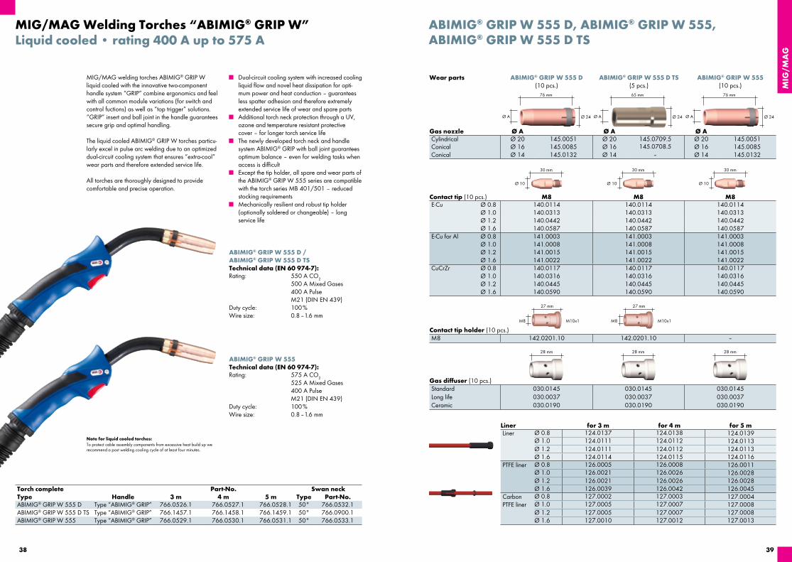
■ Dual-circuit cooling system with increased cooling liquid flow and novel heat dissipation for opti-mum power and heat conduction – guarantees less spatter adhesion and therefore extremely extended service life of wear and spare parts
■ Additional torch neck protection through a UV, ozone and temperature resistant protective cover – for longer torch service life
■ The newly developed torch neck and handle system ABIMIG® GRIP with ball joint guarantees optimum balance – even for welding tasks when access is difficult
■ Except the tip holder, all spare and wear parts of the ABIMIG® GRIP W 555 series are compatible with the torch series MB 401/501 – reduced stocking requirements
■ Mechanically resilient and robust tip holder (optionally soldered or changeable) – long service life
MIG/MAG welding torches ABIMIG® GRIP W liquid cooled with the innovative two-component handle system “GRIP” combine ergonomics and feel with all common module variations (for switch and control fuctions) as well as “top trigger” solutions. “GRIP” insert and ball joint in the handle guarantees secure grip and optimal handling.
The liquid cooled ABIMIG® GRIP W torches particu-larly excel in pulse arc welding due to an optimized dual-circuit cooling system that ensures “extra-cool” wear parts and therefore extended service life.
All torches are thoroughly designed to provide comfortable and precise operation.
MIG/MAG Welding Torches “ABIMIG® GRIP W”Liquid cooled • rating 400 A up to 575 A
ABIMIG® GRIP W 555 D /ABIMIG® GRIP W 555 D TSTechnical data (EN 60 974-7):Rating: 550 A CO2
500 A Mixed Gases 400 A Pulse M21 (DIN EN 439)
Duty cycle: 100 %Wire size: 0.8 – 1.6 mm
ABIMIG® GRIP W 555Technical data (EN 60 974-7):Rating: 575 A CO2
525 A Mixed Gases 400 A Pulse M21 (DIN EN 439)
Duty cycle: 100 %Wire size: 0.8 – 1.6 mm
Torch complete Part-No. Swan neckType Handle 3 m 4 m 5 m Type Part-No.ABIMIG® GRIP W 555 D Type “ABIMIG® GRIP” 766.0526.1 766.0527.1 766.0528.1 50° 766.0532.1ABIMIG® GRIP W 555 D TS Type “ABIMIG® GRIP” 766.1457.1 766.1458.1 766.1459.1 50° 766.0900.1ABIMIG® GRIP W 555 Type “ABIMIG® GRIP” 766.0529.1 766.0530.1 766.0531.1 50° 766.0533.1
Ø 10
30 mm
M8
27 mm
28 mm
M10x1
28 mm
Ø 10
30 mm
Ø 10
30 mm
28 mm
M8
27 mm
M10x1
Ø A Ø 24
65 mm
Ø A Ø 24
76 mm
Ø A Ø 24
76 mm
Wear parts
ABIMIG® GRIP W 555 D, ABIMIG® GRIP W 555,ABIMIG® GRIP W 555 D TS
ABIMIG® GRIP W 555 D(10 pcs.)
ABIMIG® GRIP W 555 D TS(5 pcs.)
Gas nozzle Ø A Ø A Ø ACylindrical Ø 20 145.0051 Ø 20 145.0709.5 Ø 20 145.0051Conical Ø 16 145.0085 Ø 16 145.0708.5 Ø 16 145.0085Conical Ø 14 145.0132 Ø 14 – Ø 14 145.0132
Contact tip (10 pcs.) M8 M8 M8E-Cu Ø 0.8 140.0114 140.0114 140.0114
Ø 1.0 140.0313 140.0313 140.0313Ø 1.2 140.0442 140.0442 140.0442Ø 1.6 140.0587 140.0587 140.0587
E-Cu for Al Ø 0.8 141.0003 141.0003 141.0003Ø 1.0 141.0008 141.0008 141.0008Ø 1.2 141.0015 141.0015 141.0015Ø 1.6 141.0022 141.0022 141.0022
CuCrZr Ø 0.8 140.0117 140.0117 140.0117Ø 1.0 140.0316 140.0316 140.0316Ø 1.2 140.0445 140.0445 140.0445Ø 1.6 140.0590 140.0590 140.0590
Contact tip holder (10 pcs.)M8 142.0201.10 142.0201.10 –
Gas diffuser (10 pcs.)Standard 030.0145 030.0145 030.0145Long life 030.0037 030.0037 030.0037Ceramic 030.0190 030.0190 030.0190
Liner for 3 m for 4 m for 5 mLiner Ø 0.8 124.0137 124.0138 124.0139
Ø 1.0 124.0111 124.0112 124.0113Ø 1.2 124.0111 124.0112 124.0113Ø 1.6 124.0114 124.0115 124.0116
PTFE liner Ø 0.8 126.0005 126.0008 126.0011Ø 1.0 126.0021 126.0026 126.0028Ø 1.2 126.0021 126.0026 126.0028Ø 1.6 126.0039 126.0042 126.0045
Carbon PTFE liner
Ø 0.8 127.0002 127.0003 127.0004Ø 1.0 127.0005 127.0007 127.0008Ø 1.2 127.0005 127.0007 127.0008Ø 1.6 127.0010 127.0012 127.0013
ABIMIG® GRIP W 555(10 pcs.)

MIG
/MA
G
4140
Note for liquid cooled torches:To protect cable assembly components from excessive heat build up we recommend a post welding cooling cycle of at least four minutes.
■ Dual-circuit cooling system with increased cooling liquid flow and new heat dissipation for optimal power and heat conduction – guarantees less spatter adhesion and therefore extremely extended service life of wear and spare parts
■ Additional torch neck protection through a UV, ozone and temperature resistant protective cover – for longer torch service life
■ The newly developed torch neck and handle system ABIMIG® GRIP with ball joint guarantees optimal balance – even for welding tasks when access is difficult
■ Specially designed spare and wear parts for the high-performance application range – excellent results especially in pulse arc welding
■ Gas nozzle with innovative “plug-screw connection” – optimal fixing and heat dissipation
■ Swan neck can be delivered in three versions – with soldered or changeable tip holder M10 as well as with collet body version for push-fit “click” contact tip
MIG/MAG Welding Torches “ABIMIG® GRIP W”Liquid cooled • rating 450 A up to 625 A
ABIMIG® GRIP W 605Technical data (EN 60 974-7):Rating: 625 A CO2
575 A Mixed Gases 450 A Pulse M21 (DIN EN 439)
Duty cycle: 100 %Wire size: 1.0 – 1.6 mm
ABIMIG® GRIP W 605 DTechnical data (EN 60 974-7):Rating: 600 A CO2
550 A Mixed Gases 450 A Pulse M21 (DIN EN 439)
Duty cycle: 100 %Wire size: 1.0 – 1.6 mm
ABIMIG® GRIP W 605 CTechnical data (EN 60 974-7):Rating: 600 A CO2
550 A Mixed Gases 450 A Pulse M21 (DIN EN 439)
Duty cycle: 100 %Wire size: 1.0 – 1.6 mm
Torch complete Part-No. Swan neckType Handle 3 m 4 m 5 m Type Part-No.ABIMIG® GRIP W 605 Type “ABIMIG® GRIP” 766.0537.1 766.0538.1 766.0539.1 50° 766.0541.1ABIMIG® GRIP W 605 D Type “ABIMIG® GRIP” 766.0534.1 766.0535.1 766.0536.1 50° 766.0540.1ABIMIG® GRIP W 605 C Type “ABIMIG® GRIP” 766.0543.1 766.0544.1 766.0545.1 50° 766.0542.1
Ø 12
35 mm
31 mm 31 mm 31 mm
M10
29 mm
M9x1
Ø A Ø A Ø A
77 mm 77 mm 77 mm
Ø 9.9
32 mm
19.5 mm
Ø 12
35 mm
Wear parts
ABIMIG® GRIP W 605, ABIMIG® GRIP W 605 D,ABIMIG® GRIP W 605 C
Gas nozzle (10 pcs.) Ø A Ø A Ø ACylindrical Ø 20 145.0678.10 Ø 20 145.0678.10 Ø 20 145.0678.10Conical Ø 17 145.0669 Ø 17 145.0669 Ø 17 145.0669
Gas nozzle adapter 766.1070 766.1070 766.1070
Contact tip (10 pcs.) M10 M10E-Cu Ø 1.0 140.1542.10 140.1542.10 –
Ø 1.2 140.1543.10 140.1543.10 –Ø 1.6 140.1544.10 140.1544.10 –
CuCrZr Ø 1.0 140.0348 140.0348 140.1318Ø 1.2 140.0481 140.0481 140.1319Ø 1.6 140.0616 140.0616 140.1321
Contact tip holder / Collet body (10 pcs.)Contact tip holder M10 – 142.0202.10 –Collet body – – 766.1051
Gas diffuser (10 pcs.)Long Life (Standard) 766.0518 766.0518 766.0518
Liner for 3 m for 4 m for 5 mLiner Ø 1.0 124.0111 124.0112 124.0113
Ø 1.2 124.0111 124.0112 124.0113Ø 1.6 124.0114 124.0115 124.0116
PTFE liner Ø 1.0 126.0021 126.0026 126.0028Ø 1.2 126.0021 126.0026 126.0028Ø 1.6 126.0039 126.0042 126.0045
Carbon PTFE liner
Ø 1.0 127.0005 127.0007 127.0008Ø 1.2 127.0005 127.0007 127.0008Ø 1.6 127.0010 127.0012 127.0013
ABIMIG® GRIP W 605 ABIMIG® GRIP W 605 D ABIMIG® GRIP W 605 C

MIG
/MA
G
4342
Air and liquid cooledMIG/MAG Welding Torches Push-Pull Plus
Note for liquid cooled torches:To protect cable assembly components from excessive heat build up we recommend a post welding cooling cycle of at least four minutes.
Type Cooling Rating Duty cycle Wire sizeCO2 Mixed Gases M21 (%) (mm)
Push-Pull Plus 36 D air 300 A 270 A 60 0.8–1.2Push-Pull Plus 240 D liquid 270 A 240 A 100 0.8–1.2Push-Pull Plus 401 D liquid 400 A 350 A 100 0.8–1.2
Torch complete (40 V motor) Part-No. Part-No. Part-No.Type 8 m without Poti 8 m with Poti Swan neckPush-Pull Plus 36 D; straight; GZ-2 085.0104.1 085.0106.1 085.0116.1Push-Pull Plus 36 D; 45° bend; GZ-2 085.0105.1 085.0107.1 085.0117.1Push-Pull Plus 240 D; straight; WZ-2 095.0110.1 095.0119.1 095.0040.1Push-Pull Plus 240 D; 45° bend; WZ-2 095.0111.1 095.0120.1 095.0052.1Push-Pull Plus 401 D; straight; WZ-2 095.0100.1 095.0114.1 095.0002Push-Pull Plus 401 D; 45° bend; WZ-2 095.0101.1 095.0115.1 095.0015
The screw-type torch necks can be replaced quickly. They are available as either straight or 45° angled versions. A special interface between the handle and the torch neck makes it possible to turn the necks up to 360°. All torches, both air and liquid-cooled for capacities of up to 400 A, are based on the tried-and-trusted “MB” torch neck design.
The main areas of application for these welding torches include wharfs, manufacturers of containers and ships etc., as well as in vehicle and wagon building. Wherever exact and constant wire feeding is an absolute must.
■ Identical motor characteristics as standard Push-Pull
■ Consistent and problem-free wire feeding thanks to a powerful pull motor
■ Precise contact pressure regulation of the wire feeding rollers directly on the torch
■ Available with optional potentiometer for speed regulation
■ Wearing parts are identical to those of the tried-and-trusted MB torch series – minimised stocking
■ Optimum torch cooling – long tool lives ■ Sturdy design – long service life
The welding torches of the Push-Pull Plus series, specially developed for aluminum welding require-ments and the use of thin wires, makes problem-free and consistent wire feed and constant wire feed possible, even with longer cable assemblies. A powerful, sturdy pull motor with potentiometer guarantees exact speed regulation. For an optimum wire feed without frictional loss, the contact pressure of the feeding rollers can be regulated precisely and easily directly on the handle. The ergonomic handle ensures optimum, low-fatigue handling.
Wire feeding roll Ø 0.8 Ø 1.0 Ø 1.2ST/AL 095.0064.1 095.0065.1 095.0066.1
Ø C Ø 24
76 mm
Ø 10Ø 8
30 mm28 mm
M6 / M8
25 mm
M10x1
28 mm
26 mm
M6 / M8
28 mm
20 mm32.5 mm
M6 M6M8
Ø 10Ø 8 Ø 8
30 mm28 mm 28 mm
84 mm
Ø 24
63.5 mm
Ø A Ø B Ø 20
Push-Pull Plus 36 D Push-Pull Plus 240 D Push-Pull Plus 401 D
Push-Pull Plus 36, Push-Pull Plus 240, Push-Pull Plus 401
Wear parts
Gas nozzle (10 pcs.) Ø A Ø B Ø CCylindrical Ø 19 145.0045 Ø 17 145.0047 Ø 20 145.0051Conical Ø 16 145.0078 Ø 12.5 145.0080 Ø 16 145.0085Conical Ø 12 145.0126 Ø 10 145.0128 Ø 14 145.0132
Contact tip (10 pcs.) M6 M8 M6 M6 M8E-Cu Ø 0.8 140.0051 140.0114 140.0051 140.0051 140.0114
Ø 1.0 140.0242 140.0313 140.0242 140.0242 140.0313Ø 1.2 140.0379 140.0442 140.0379 140.0379 140.0442
E-Cu for Al Ø 0.8 141.0001 141.0003 141.0001 141.0001 141.0003Ø 1.0 141.0006 141.0008 141.0006 141.0006 141.0008Ø 1.2 141.0010 141.0015 141.0010 141.0010 141.0015
CuCrZr Ø 0.8 140.0054 140.0117 140.0054 140.0054 140.0117Ø 1.0 140.0245 140.0316 140.0245 140.0245 140.0316Ø 1.2 140.0382 140.0445 140.0382 140.0382 140.0445
Contact tip holder (10 pcs.)M6 142.0005 142.0003 142.0008M8 142.0020 – 142.0022
Gas diffuser (10 pcs.)Standard 014.0261 012.0183 030.0145Long life 014.0026 – 030.0037Ceramic 014.0023 – 030.0190
LinerNeck liner1 0.8–1.0 mm 149.0260.3 149.0264.3 149.0264.3Neck liner1 1.2 mm 149.0261.3 149.0265.3 149.0265.3Neck liner2 0.8–1.0 mm 149.0262.3 149.0266.3 149.0266.3Neck liner2 1.2 mm 149.0263.3 149.0267.3 149.0267.3Liner blank 0.8 mm 122.0010 122.0010 122.0010Liner blank 1.0–1.2 mm 122.0040 122.0040 122.0040Liner insulated 0.8 mm 124.0169 124.0169 124.0169PTFE liner 0.8 mm 126.0013 126.0013 126.0013PTFE liner1.0–1.2 mm 126.0030 126.0030 126.0030Carb. PTFE liner 0.8 mm 127.0015 127.0015 127.0015Carb. PTFE l. 1.0–1.2 mm 127.0009 127.0009 127.0009PA liner 1.0–1.2 mm 128.0019 128.0019 128.0019 ¹ For straight torch necks (0°). ² For bended torch necks (45°).

MIG
/MA
G
4544
■ Aluminium extraction tube – considerable weight saving
■ Handle with extraction control and swivel joint – optimized handling
■ Smaller diameter extraction hoses for all types – lower handling weight, optimum flexibility
■ Considerable weight reduction of air cooled torches due to the innovative ABICOR BINZEL Low-Weight Bikox®
Every welding job generates fumes and smoke that could be hazardous if inhaled. Based on the well- established torch series “MB” the RAB GRIP Fume Extraction Torches offer efficient fume extrac-tion through the torch itself. Special design solutions guarantee highly efficient smoke removal directly at its source without affecting the protective gas shield.
■ Direct extraction at the arc – ensures protection of the welder’s respiratory system
■ Problem free installation in all existing MIG/MAG work stations
■ Small extraction tube diameter – better accessi bility
Air and liquid cooledMIG/MAG Fume Extraction Torches “RAB GRIP”
Torch complete Part-No.Type Connection 3 m 4 m 5 mRAB GRIP 15 AK Central connection KZ-2 602.3008.1 602.3009.1 602.3010.1RAB GRIP 24 KD Central connection KZ-2 612.3007.1 612.3008.1 612.3009.1RAB GRIP 25 AK Central connection KZ-2 604.3007.1 604.3008.1 604.3009.1RAB GRIP 36 KD Central connection KZ-2 614.3007.1 614.3008.1 614.3009.1RAB GRIP 240 D Central connection WZ-2 623.3011.1 623.3012.1 623.3013.1RAB GRIP 501 Central connection WZ-2 632.3015.1 632.3016.1 632.3017.1RAB GRIP 501 D Central connection WZ-2 634.3030.1 634.3031.1 634.3032.1
Torch complete Part-No.Type Connection 3 m 4 m 5 mRAB GRIP 15 AK Central connection KZ-2 602.3001.1 602.3002.1 602.3003.1RAB GRIP 24 KD Central connection KZ-2 612.3001.1 612.3002.1 612.3003.1RAB GRIP 25 AK Central connection KZ-2 604.3001.1 604.3002.1 604.3003.1RAB GRIP 36 KD Central connection KZ-2 614.3001.1 614.3002.1 614.3003.1RAB GRIP 240 D Central connection WZ-2 623.3003.1 623.3004.1 623.3005.1RAB GRIP 501 Central connection WZ-2 632.3003.1 632.3004.1 632.3005.1RAB GRIP 501 D Central connection WZ-2 634.3003.1 634.3004.1 634.3005.1RAB GRIP 155 Central connection KZ-2 602.D008.1 602.D001.1 602.D009.1RAB GRIP 255 Central connection KZ-2 604.D001.1 604.D002.1 604.D003.1RAB GRIP 355 Central connection KZ-2 614.D004.1 614.D005.1 614.D006.1
Suction nozzle with spring clip, feed air slide below*
*Module solutions on demand.
Suction nozzle with Quicklock, feed air slide on top
RAB GRIP specific wear parts
MIG/MAG Fume Extraction Torches in action …
Note for liquid cooled torches:To protect cable assembly components from excessive heat build up we recommend a post welding cooling cycle of at least four minutes.
RAB GRIP
Type Cooling Rating Duty cycle Wire sizeCO2 Mixed Gases M21 (%) (mm)
RAB GRIP 15 AK air 180 A 150 A 60 0.6–1.0RAB GRIP 24 KD air 250 A 220 A 60 0.8–1.2RAB GRIP 25 AK air 230 A 200 A 60 0.8–1.2RAB GRIP 36 KD air 300 A 270 A 60 0.8–1.2RAB GRIP 240 D liquid 300 A 270 A 100 0.8–1.2RAB GRIP 501 liquid 550 A 500 A 100 1.0–1.6RAB GRIP 501 D liquid 500 A 450 A 100 1.0–1.6RAB GRIP 155 air 190 A 170 A 60 0.6–1.0RAB GRIP 255 air 240 A 210 A 60 0.8–1.2RAB GRIP 355 air 270 A 270 A 60 1.0–1.6
Type Suction nozzle spring clip Suction nozzle QuicklockRAB GRIP 15 AK 600.2047.1 600.3017.1RAB GRIP 24 KD 600.2045.1 600.3018.1RAB GRIP 25 AK 600.2046.1 600.3019.1RAB GRIP 36 KD 600.2044.1 600.3009.1RAB GRIP 240 D 600.2045.1 600.3018.1RAB GRIP 501 600.2044.1 600.3009.1RAB GRIP 501 D 600.2044.1 600.3009.1
Replacement spring clip for the fixation of the suction nozzle on request. Suction funnel (replaces the suction nozzle) on request.
Type Swan neck Outer neck Gas nozzle holderRAB GRIP 15 AK 602.3004.1 600.3007.1 902.0007RAB GRIP 24 KD 612.2001 600.2002 –RAB GRIP 25 AK 604.2001 600.3007.1 –RAB GRIP 36 KD 614.2001 600.2002 –RAB GRIP 240 D 623.3001.1 600.2002 –RAB GRIP 501 632.3001.1 632.2009 –RAB GRIP 501 D 634.3001.1 600.2002 –
The wear parts – contact tip, gas nozzle, gas diffuser, contact tip holder, neck liner or liner – are identical with those of the manual welding torches of same size.
Technical Data
Type Suction nozzle spring clip
Swan neck Outer neck
RAB GRIP 155 600.D007.1 602.D002.1 600.3007.1RAB GRIP 255 600.2004 604.D004.1 600.3007.1RAB GRIP 355 600.D045 614.D001 600.2002
Replacement spring clip for the fixation of the suction nozzle on request. Suction funnel (replaces the suction nozzle) on request
RAB GRIP with fume extractionMIG/MAG without fume extraction

MIG
/MA
G
4746
FES-200 and FES-200 W3Fume Extraction System
Mobile, powerful and easy to use! The Fume Extraction System FES-200 – for optimum extraction of contaminants with fume extraction directly at the arc. The W3 version is certified for all CrNi-steels!
The high-vacuum extraction unit FES-200 and FES-200 W3 with the RAB GRIP torches constitutes the perfect system to extract welding fumes most effectively. Hence, the welder and his environment are best protected, and the most productive work enabled.
■ Weighs approx. 23 kg ■ Automatic Start/Stop function included in
basic equipment ■ Integrated manual filter cleaning system for
longer uses ■ A filter contamination meter; only clean when
necessary ■ IFA certified W3-License
The FES-200 W3 was developed especially to meet the demands of chrome and nickel material joining, and is certified by the Institute of Work Safety with the W3 license for all welding applications or related procedures with emissions suitable to KMR / 1.2 materials*. Thus, this device enables the filtering of the exhaust, and work to be conducted without these other wise harmful effects.
*List of carcinogenic, mutagenic, or toxic to reproduction materials
3 4 5 6
7 8 9 10
1 2
Fume Extraction System & Accessories
Complete extraction unit
Pos. Description Part-No.1 Complete unit FES-200 (230 V) 601.0001.1
Complete unit FES-200 (115 V) 601.0002.12 Complete unit FES-200 W3 (230 V) 601.0034.13 Carbon brush (230 V) 601.0005.1
Carbon brush (115 V) 601.0017.14 Filter cartridge FES-200 601.0008.1
Filter cartridge FES-200 W3 601.0048.15 Hose with sleeve, L = 5.00 m 601.0015.16 Adapter ring (connection for two hoses) 601.0046.17 Start/Stop shunt, 7-pole 601.0020.1not ill. Start/Stop shunt, 4-pole 601.0041.18 Dust collection bag (w/o pan) 601.0021.109 Exhaust casting FES-200 (optional) 601.0023.110 Adapter ring FES-200 / RAB Plus (50 / 44 mm) 601.0031.1
Replacement parts and accessories
Extraction unit package includes: ■ Extraction hose with sleeve ■ Start/Stop shunt ■ 10 dust collection bags ■ Filter cartridge

MIG
/MA
G
4948
Machine welding processes are used wherever high precision and productivity is required. Accessibility to the components very often requires special solutions with mechanical torches. ABICOR BINZEL offers an almost infinite variety of solutions, always based on the design of the world-wide recognized manual tor ches.
This means, experience in service life and quality offers additional advantages, so that special parts are not required.
Your ABICOR BINZEL advantages:
■ Expert competence ■ Separate special torch production –
short delivery time ■ High availability ■ Right solution for every job
Note for liquid cooled torches:To protect cable assembly components from excessive heat build up we recommend a post welding cooling cycle of at least four minutes.
MIG/MAG Machine Welding TorchesAir and liquid cooled
Ø A
X
Y
Ø B
X
Y
Ø BØ A
Changeable swan neckFixed swan neck
MIG/MAG Machine Welding Torches
Type Geometry Part-No. X YAUT 24 KD 0° 912.0001 154 mmAUT 24 KD 45° 912.0002 125 mm 80 mmAUT 25 KD 0° 904.0003 140 mmAUT 25 KD 45° 904.0004 110 mm 75 mmAUT 26 / 36 KD 0° 914.0002 185 mmAUT 26 / 36 KD 45° 914.0001 145 mm 95 mmAUT 240 D 0° 923.0001 154 mmAUT 240 D 45° 923.0002 126 mm 73 mmAUT 501 0° 932.0001 167 mmAUT 501 45° 932.0002 135 mm 82 mmAUT 501 D 0° 934.0001 167 mmAUT 501 D 45° 934.0002 135 mm 82 mmABIMIG® W 555 MT 0° 766.0878.1 175 mmABIMIG® W 555 MT 22° 766.0879.1 168 mm 38 mmABIMIG® W 555 MT 45° 766.0880.1 144 mm 84 mmABIMIG® W 555 D MT 0° 766.0865.1 175 mmABIMIG® W 555 D MT 22° 766.0866.1 168 mm 38 mmABIMIG® W 555 D MT 45° 766.0867.1 144 mm 84 mmABIMIG® W 605 MT 0° 766.0883.1 184 mmABIMIG® W 605 MT 22° 766.0884.1 176 mm 41 mmABIMIG® W 605 MT 45° 766.0885.1 150 mm 90 mmABIMIG® W 605 D MT 0° 766.0871.1 183.5 mmABIMIG® W 605 D MT 22° 766.0872.1 176 mm 41 mmABIMIG® W 605 D MT 45° 766.0873.1 150 mm 90 mmABIMIG® 645 W MT 0° 766.0459 182 mmABIMIG® 645 W MT 45° 766.0460 149 mm 89 mm
Type Geometry Part-No. X YABIMIG® MT 255 T8M 0° 012.D122 195 mmABIMIG® MT 255 T8M 45° 004.D785 140 mm 85 mmABIMIG® MT 355 T8M 0° 014.D812 224 mmABIMIG® MT 355 T8 M 45° 014.D808 185 mm 95 mmABIMIG® MT 455 T8M 0° 016.D250 230 mmABIMIG® MT 455 T8M 45° 016.D225 190 mm 100 mm
Changeable swan neck
Fixed swan neck
Order information:
When ordering complete torches, please indicate the torch type, torch geometry (straight or 45° bent) and dimension ”L” (see sketch).
The wear parts – contact tip, gas nozzle, gas diffuser, contact tip holder, neck liner or liner – are identical with those of the manual welding torches of same size.air cooled torches: 37 mm
liquid cooled torches: 40 mmair cooled torches: 38 mmliquid cooled torches: 38 mm
Dimension L

51
Notes
50
MIG/MAG Gas nozzles and Contact tipsBent gas nozzles and contact tips forMB 15 / 24 / 26 and MB 240 / 401 / 501
Discription Welding wireFor MB 15AK
Part-No.
Gas nozzle bent D12 ID16 L68 – – 145.D368Contact tip E-Cu M6 / 1.0/35.5 bend D=6 / R31 Up to 1.0 mm 140.D468.10Hexagon nut M6 SW8 – – 001.D220.10
These special gas nozzle and contact tip packages are available for use of MB torches in special appli-cations in welding postions with limited accessibility.The bent contact tip can be turned into the desired position and can be fixed by a counter nut.
For MB 240D and MB 24KDGas nozzle bent OD20 ID17 L82 NI Typ 24 / 240 – 145.D457.5Contact tip E-Cu M6 / 0.8 bend D=6 / R40 0.8 mm 1401666.10Contact tip E-Cu M6 / 1.0 bend D=6 / R40 1.0 mm 147.D476.10Contact tip E-Cu M6 / 1.2 bend D=6 / R40 1.2 mm 147.D478.10Hexagon nut M6 SW8 – – 001.D220.10
For MB 401D / 501D and MB 26KDGas nozzle bent OD24 ID20 L95 NI Typ 24 / 240 – 145.D460.5Contact tip CuCrZr M8 / 1.0 bend D=8 / R36 silver plated Up to 1.0 mm 147.D481.10Contact tip CuCrZr M8 / 1.2 bend D=8 / R36 silver plated 1.2 mm 147.D482.10Hexagon nut M8 SW11 – – 001.D221.10
Bent contact tips for higher amperages are siver plated.All bent gas nozzles are slip-on gas nozzles and, therefore, can be easily positioned according to the contact tip.

MIG
/MA
G
5352
Bikox®, Control cables, Hoses and Liners
Type Description Cable assembly length3 m 4 m 5 m 8 m per m
MB EVO 240 / 401 / 501 Power cable PVC 115.0833.1 115.0834.1 115.0835.1 – –MB EVO PRO 240 / 401 / 501 Power cable FRH 115.0830.1 115.0831.1 115.0832.1 – –ABIMIG® W 340 / 440 / 540 Power cable PVC 115.0855.1 115.0856.1 115.0857.1 – –ABIMIG® W T 340 / 440 / 540 Power cable PVC 115.0581 115.0582 115.0583 – –ABIMIG® GRIP W 555 / 605 Power cable PVC 115.0581 115.0582 115.0583 – –RAB GRIP 240 / 501 Power cable PVC 115.0581 115.0582 115.0583 – –PP Plus 240 / 401 Power cable PVC – – – 115.0043 –
ABIMIG® GRIP W 555 / 605 Wire conduit 156.0275 156.0276 156.0277 – –RAB GRIP 240 / 501 Wire conduit 154.0002 154.0003 154.0004 – –PP Plus 240 / 401 Wire conduit – – – 156.0273 –
MB EVO 240 / 401 / 501 Water hose blue PVC – – – – 109.0057MB EVO PRO 240 / 401 / 501 Water hose black FRH – – – – 109.0052ABIMIG® W 340 / 440 / 540 Water hose blue PVC – – – – 109.0057ABIMIG® W T 340 / 440 / 540 Water hose blue PVC – – – – 109.0057ABIMIG® GRIP W 555 / 605 Water hose blue PVC – – – – 109.0057ABIMIG® GRIP W 555 / 605 Water hose red PVC – – – – 109.0056RAB GRIP 240 / 501 Water hose blue PVC – – – – 109.0057RAB GRIP 240 / 501 Water hose red PVC – – – – 109.0056PP Plus 240 / 401 Water hose blue PVC – – – – 109.0057PP Plus 240 / 401 Water hose red PVC – – – – 109.0056
ABIMIG® GRIP W 555 / 605 Gas hose – – – – 109.0040RAB GRIP 240 / 501 Gas hose – – – – 109.0040PP Plus 240 / 401 Gas hose – – – – 109.0040
II. Cable assemblies liquid cooled
I. Cable assemblies air cooled
Type Bikox® Cable assembly length3 m 4 m 5 m 8 m
MB EVO 15 R10 160.1291.1 160.1292.1 160.1293.1 –MB EVO 24 R25 160.D427 160.D428 160.D429 –MB EVO 25 R20 160.1294.1 160.1295.1 160.1296.1 –MB EVO 26 R30 160.1305.1 160.1306.1 160.1307.1 –MB EVO 36 R40 160.1308.1 160.1309.1 160.1310.1 –MB EVO PRO 15 R18 LW 160.H025.1 160.H026.1 160.H027.1 –MB EVO PRO 24 R37 LW 160.1330.1 160.1331.1 160.1332.1 –MB EVO PRO 25 R28 LW 160.H032.1 160.H033.1 160.H034.1 –MB EVO PRO 26 R42 LW 160.H039.1 160.H040.1 160.H041.1 –MB EVO PRO 36 R53 LW 160.H046.1 160.H047.1 160.H048.1 –ABIMIG® A 155 LW / R18 LW 160.H025.1 160.H026.1 160.H027.1 –ABIMIG® A T 155 LW / RAB GRIP 15 ABIMIG® A 255 LW / R28 LW 160.H032.1 160.H033.1 160.H034.1 –ABIMIG® A T 255 LW / RAB GRIP 25 ABIMIG® A 305 LW / R42 LW 160.H039.1 160.H040.1 160.H041.1 –ABIMIG® A T 305 LW / RAB GRIP 24 ABIMIG® A 355 LW / R53 LW 160.H046.1 160.H047.1 160.H048.1 –ABIMIG® A T 355 LW / RAB GRIP 36 ABIMIG® A 405 LW RA70 LW 160.H344.1 160.H345.1 160.H346.1 –ABIMIG® A T 405 LW PP Plus 36 D Type 35 – – – 118.0074
Bikox®, Control cables, Hoses and Liners
V. Hose clamps, Quick connector and Marking washer
IV. Outer and Suction Hose
VII. Liner for special wire
Type Description Cable assembly length3 m 4 m 5 m 8 m per m
MB EVO 240 / 401 / 501 Outer hose 25x1.5 107.0109.1 107.0110.1 107.0111.1 – –MB EVO PRO 240 / 401 / 501 Outer hose 25x1.5 107.0109.1 107.0110.1 107.0111.1 – –ABIMIG® W 340 / 440 / 540 Outer hose 25x1.5 107.0109.1 107.0110.1 107.0111.1 – –ABIMIG® W T 340 / 440 / 540 Outer hose 25x1.5
(with cable support)107.0079 107.0044 107.0080 – –
ABIMIG® GRIP W 555 / 605 Outer hose 25x1.5 – – – 107.0004RAB GRIP 15 / 24 / 25 / 36RAB GRIP 155 / 255 / 355
Outer hose LW 32 – – – 109.0043
RAB GRIP 240 / 501 Outer hose LW 38 – – – 109.0044PP Plus 36 / 240 / 401 Outer hose 25x1.5 – – – 107.0004
Type Pcs. Part-No. for hose109.0040 109.0052 109.0056 109.0057
Hose clamp Ø=8.7 100 171.0002 •Hose clamp Ø=9.0 with ring (mark. 9.5) 100 173.0001 • •Hose clamp Ø=9.5 with ring (mark.10.0) 100 173.0002 •Quick connector NW 5 / Ø=6.0 20 501.0114 • • •Marking washer red 20 501.2166 •Marking washer blue 20 501.2167 •Fastener cap red 20 501.2423 • •Fastener cap blue 20 501.2424 • •
Liner Color Ø inside / outside for wire size for 3 m for 4 m for 5 m for 8 mPA liner grey 2.0 / 4.0 1.0–1.2 128.0012 128.0015 128.0016 128.0019PA liner grey 2.3 / 4.7 1.6 128.0020 128.0021 128.0030 128.0023PA liner grey 2.9 / 4.7 2.4 128.0024 128.0025 128.0027 128.0032PA linerwith inlet cone
grey 2.3 / 4.7 1.2–1.6 128.0058.1 128.0059.1 128.0060.1 –
VI. Combined wire guides
Type for wire size for 3 m for 4 m for 5 m for 8 mPTFE / Brass 0.8 126.M002 126.M003 126.M004 –PTFE / Brass 1.0–1.2 126.M006 126.M007 126.M008 –PTFE / Brass 1.6 126.M009 126.M010 126.M011 –Carbon-PTFE / Brass 0.8 127.M002 127.M003 127.M004 –Carbon-PTFE / Brass 1.0–1.2 127.M006 127.M007 127.M008 –PA / Brass 1.0–1.2 128.M002 128.M003 128.M004 –P (for ABIMIG® A / A T 405 LW) 1.0 126.D026.1 126.D027.1 126.D028.1 –P (for ABIMIG® A / A T 405 LW) 1.2–1.4 126.D029.1 126.D030.1 126.D031.1 –
Type Description Cable assembly length3 m 4 m 5 m 8 m per m
MB EVO 240 / 401 / 501 Gas /wire hose 154.0017.1 154.0018.1 154.0019.1MB EVO PRO 240 / 401 / 501 Gas /wire hose 154.0017.1 154.0018.1 154.0019.1 – –ABIMIG® W 340 / 440 / 540 Gas /wire hose 154.0020.1 154.0021.1 154.0022.1 – –ABIMIG® W T 340 / 440 / 540 Gas /wire hose 109.0094.1 115.0095.1 115.0096.1 – –All torches Control cable 2-pole – – – – 100.0019
VIII. BPL-Liner
Liner Color Ø inside / outside for wire size for 3 m for 4 m for 5 m for 8 mBPL-liner orange 2.0 / 4.7 0.8–1.2 126.0069 126.0070 126.0071 –BPL-liner grey 2.7 / 4.7 1.6 126.0072 126.0073 126.0074 –
III. Cable assemblies liquid cooled

MIG
/MA
G
5554
Handles and control modules ABIMIG A T / W T
X. Handle ABIMIG® A T / W T with module
IX. Handle ABIMIG® A T / W T without module
Type Description Part-No.ABIMIG® A T LW 155 / 255 / 305 / 355 / 405 Trigger long, blind cover 180.D077.1ABIMIG® A T LW 155 / 255 / 305 / 355 / 405 Trigger short, blind cover 180.D078.1Cable support ABIMIG® A T LW short 400.D574.1Half rings for cable support A T 1 pair 400.D561.2ABIMIG® W T 340 / 440 / 540 Trigger long, blind cover 180.0164.1ABIMIG® W T 340 / 440 / 540 Trigger short, blind cover 180.0165.1Half rings for cable support W T 1 pair 400.D561.2
Trigger long, blind coverPart-No.: 180.D077.1
Trigger short, blind coverPart-No.: 180.D078.1
Trigger long, Up/DownPart-No.: 180.D079.1
Trigger short, Up/DownPart-No.: 180.D080.1
Type Description Part-No.ABIMIG® A T LW 155 / 255 / 305 / 355 / 405 Trigger long, incl. module BIS-52
Up/Down 2x push-button (400.1292.1)180.D079.1
ABIMIG® A T LW 155 / 255 / 305 / 355 / 405 Trigger short, incl. module BIS-52 Up/Down 2x push-button (400.1292.1)
180.D080.1
Cable support ABIMIG® A T LW short 400.D574.1Half rings for cable support A T 1 pair 400.D561.2ABIMIG® W T 340 / 440 / 540 Trigger long, incl. module BIS-52
Up/Down 2x push-button (400.1292.1)180.0166.1
ABIMIG® W T 340 / 440 / 540 Trigger short, incl. module BIS-52 Up/Down 2x push-button (400.1292.1)
180.0167.1
Half rings for cable support W T 1 pair 400.D561.2
Handles and control modules ABIMIG A / W
XII. Handle ABIMIG® A / W with module
XI. Handle ABIMIG® A / W without modules
Type Description Part-No.ABIMIG® A LW 155 / 255 / 305 / 355 / 405 Trigger long, blind cover 180.0180.1ABIMIG® A LW 155 / 255 / 305 / 355 / 405 Trigger short, blind cover 180. 0181.1Cable support ABIMIG® A LW short 400.D574.1Half rings (fixes cable protection on handle) 1 pair 400.D561.2ABIMIG® W 340 / 440 / 540 Trigger long, blind cover 180.0180.1ABIMIG® W 340 / 440 / 540 Trigger short, blind cover 180.0181.1Half rings (fixes cable protection on handle) 1 pair 400.D561.2
Trigger long, blind coverPart-No.: 180.0180.1
Trigger short, blind coverPart-No.: 180.0181.1.1
Trigger long, Up/DownPart-No.: 180.D082.1
Trigger short, Up/DownPart-No.: 180.D083.1
Type Description Part-No.ABIMIG® A LW 155 / 255 / 305 / 355 / 405 Trigger long, incl. module BIS-52
Up/Down 2x push-button (400.1292.1)180.0182.1
ABIMIG® A LW 155 / 255 / 305 / 355 / 405 Trigger short, incl. module BIS-52 Up/Down 2x push-button (400.1292.1)
180.D083.1
Cable support short 400.D574.1Half rings (fixes cable protection on handle) 1 pair 400.D561.2ABIMIG® W 340 / 440 / 540 Trigger long, incl. module BIS-52
Up/Down 2x push-button (400.1292.1)180.0182.1
ABIMIG® W 340 / 440 / 540 Trigger short, incl. module BIS-52 Up/Down 2x push-button (400.1292.1)
180.0183.1
Half rings for cable support W 1 pair 400.D561.2

5756
Handles and control modules RAB GRIP
XVI. Handles RAB GRIP with modules
XV. Handles RAB GRIP without modules
Type Description Part-No.RAB GRIP 15 / 24 / 25 / 36 / 240 / 501 Handle Type Standard (feed air slide below) 180.0138.1RAB GRIP 15 / 24 / 25 / 36 / 240 / 501 Handle Type ZO (feed air slide on top) 180.0144.1Connector RAB GRIP 15 / 24 / 25 / 36 air cooled 600.2008Connector RAB GRIP 240 / 501 liquid cooled 600.0080
RAB GRIP Standard, feed air slide belowPart-No.: 180.0138.1
RAB GRIP ZO, feed air slide on topPart-No.: 180.0144.1
RAB GRIP SH, feed air slide belowPart-No.: 180.0154.1
Type Description Part-No.RAB GRIP 15 / 24 / 25 / 36 / 240 / 501 Handle Type SH without module (feed air slide below) 180.0154.1Connector RAB GRIP 15 / 24 / 25 / 36 air cooled 600.2008Connector RAB GRIP 240 / 501 liquid cooled 600.0080Module push-button BIS-51 400.1296.1Module Up/Down 2x push-button BIS-52 400.1292.1
BIS-51Control module push-button
BIS-52Control module Up/Down 2x push-button
Handles and control modules EVO PRO / EVO
XIV. Handle MIG/MAG Welding Torches “MB EVO” air cooled / liquid cooled
XIII. Handle MIG/MAG Welding Torches “MB EVO PRO” air cooled / liquid cooled
Type Description Part-No.MB EVO 15 / 24 / 25 / 26 / 36 Handle 2K MB EVO, 2 pole ac complete 180.0178.1MB EVO 240 / 401 / 501 Handle 2K MB EVO, 2 pole lc complete 180.0179.1Cable support short 400.D574.1Half rings (fixes cable protection on handle) 1 pair 400.D561.2
Type Description Part-No.MB EVO PRO 15 / 24 / 25 / 26 / 36 Handle 2K MB EVO PRO, 2 pole ac complete 180.0176.1MB EVO PRO 240 / 401 / 501 Handle 2K MB EVO PRO, 2 pole lc complete 180.0177.1Cable support short 400.D574.1Half rings (fixes cable protection on handle) 1 pair 400.D561.2
air cooledPart-No.: 180.0176.1
liquid cooledPart-No.: 180.0177.1
air cooledPart-No.: 180.0178.1
liquid cooledPart-No.: 180.0179.1

MIG
/MA
G
5958
Handles and control modulesABIMIG® GRIP
for all torch types MB ERGO / MB GRIP / ABIMIG® GRIP 155–355 for using the handles Type ABIMIG® GRIP / ABIMIG® GRIP SH / ABIMIG® GRIP TO Part-No.: 400.1341.1
Handles and control modulesABIMIG® GRIP
BIS-01LControl module with potentiometerleft 10 kΩ
BIS-01RControl module with potentiometerright 10 kΩ
Handle Type “ABIMIG® GRIP SH”
incl. add-on for control modules
Part-No.: 180.0133.1
BIS-02Control module with potentiometerleft 10 kΩ LED for Migatronic
BIS-06Control module with push-button and 4 LED
BIS-10AControl module Up/Down switch lengthwise
BIS-10BControl module Up/Down switch crosswise
BIS-10DControl module Up/Down switch crosswise for Fronius
BIS-13AControl module Up/Down 2x switch lengthwise for EWM
BIS-18Control module Up/Down 2x push-button for Cloos
Handle Type “ ABIMIG® GRIP S”
Handle Type “ABIMIG® GRIP TO”
Part-No.: 180.0132.1
cpl. with top triggerPart-No.: 180.0134.1
BIS-07BControl module Up/Down 7-segment switch crosswise
BIS-19Control module push-button 3-step
XVIII. Handle Type SH and control modules / Handle Type TO and control modules
Type Description Details Part-No.all ABIMIG® GRIP Torches Handle Type ABIMIG® GRIP SH, without control module 180.0133.1all ABIMIG® GRIP Torches Control module with potentiometer left 10 kΩ BIS-01L 400.0956
Control module with potentiometer right 10 kΩ BIS-01R 400.0957Control module with potentiometer left 10 kΩ LED for Migatronic BIS-02 400.0958Control module with push-button and 4 LED BIS-06 400.0959Control module Up/Down 7-segment switch crosswise BIS-07B 400.0961Control module Up/Down switch lengthwise BIS-10A 400.0963Control module Up/Down switch crosswise BIS-10B 400.0964Control module Up/Down switch crosswise for Fronius BIS-10D 400.1085Control module Up/Down 2x switch lengthwise for EWM BIS-13A 400.0966Control module Up/Down 2x push-button for Cloos BIS-18 400.1545.1Control module push-button 3-step BIS-19 400.1088
All ABIMIG® GRIP Torches Handle Type ABIMIG® GRIP TO (top trigger) 180.0134.1
XVII. Handles ABIMIG® GRIP / Handle tubes AUT, MT
Type Description Part-No.ABIMIG® GRIP W 555 / 605 Handle Type ABIMIG® GRIP S 180.0132.1Ball joint cable protection ABIMIG® GRIP W liquid cooled 400.1392.1Inner ring ABIMIG® GRIP W for ball joint cable protection (400.1392.1), liquid cooled 400.0790AUT 24 / 25 / 26 / 36 / 240 / 401 / 501 Handle tube AUT 180.0097ABIMIG® W MT 555 / 605 / 645 Handle tube MT 180.0114
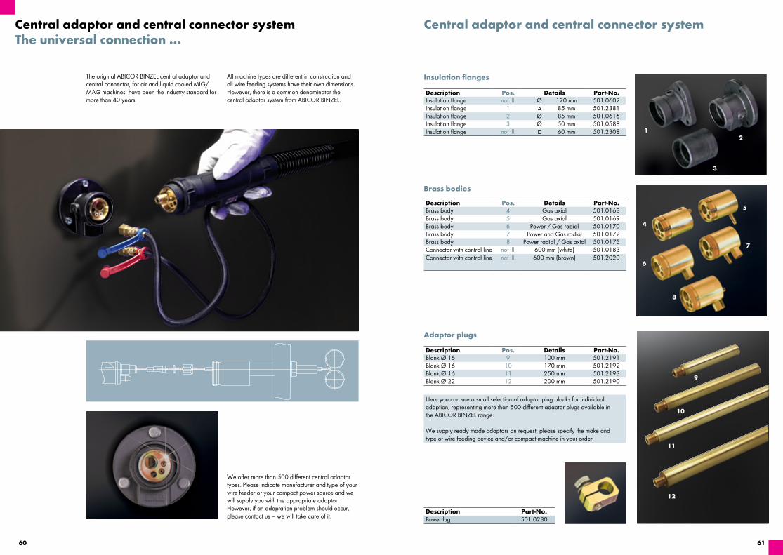
6160
Central adaptor and central connector systemThe universal connection …
The original ABICOR BINZEL central adaptor and central connector, for air and liquid cooled MIG/MAG machines, have been the industry standard for more than 40 years.
All machine types are different in construction and all wire feeding systems have their own dimensions. However, there is a common denominator the central adaptor system from ABICOR BINZEL.
We offer more than 500 different central adaptor types. Please indicate manufacturer and type of your wire feeder or your compact power source and we will supply you with the appropriate adaptor. However, if an adaptation problem should occur, please contact us – we will take care of it.
Here you can see a small selection of adaptor plug blanks for individual adaption, representing more than 500 different adaptor plugs available in the ABICOR BINZEL range.
We supply ready made adaptors on request, please specify the make and type of wire feeding device and/or compact machine in your order.
Adaptor plugs
Description Part-No.Power lug 501.0280
Description Pos. Details Part-No.Blank Ø 16 9 100 mm 501.2191Blank Ø 16 10 170 mm 501.2192Blank Ø 16 11 250 mm 501.2193Blank Ø 22 12 200 mm 501.2190
Central adaptor and central connector system
Insulation flanges
Brass bodies
Description Pos. Details Part-No.Insulation flange not ill. Ø 120 mm 501.0602Insulation flange 1 85 mm 501.2381Insulation flange 2 Ø 85 mm 501.0616Insulation flange 3 Ø 50 mm 501.0588Insulation flange not ill. 60 mm 501.2308
Description Pos. Details Part-No.Brass body 4 Gas axial 501.0168Brass body 5 Gas axial 501.0169Brass body 6 Power / Gas radial 501.0170Brass body 7 Power and Gas radial 501.0172Brass body 8 Power radial / Gas axial 501.0175Connector with control line not ill. 600 mm (white) 501.0183Connector with control line not ill. 600 mm (brown) 501.2020
12
3
4
5
6
7
8

MIG
/MA
G
6362
Central adaptor and central connector system
Capillary tubes
Description Details Part-No.Capillary tubes for wire up to Ø 1.0 mm 200 mm 129.0164
300 mm 129.0187500 mm 129.0189
1000 mm 129.0107Capillary tubes for wire up to Ø 1.6 mm 200 mm 129.0313
300 mm 129.0357500 mm 129.0361
1000 mm 129.0227Capillary tubes for wire Ø 2.0 and 2.4 mm 200 mm 129.0395
300 mm 129.0411500 mm 129.0412
1000 mm 129.0366
Guide tubes
Description Details Part-No.Guide tubes for liners 200 mm 129.0461Guide tubes for liners 300 mm 129.0471Guide tubes for liners 500 mm 129.0473Guide tubes for liners 1000 mm 129.0426
The guide tubes must be fitted as shown in the assembly instructions on page 41.
Central adaptor with spring contacts
The central adaptor that always produces a good connection thanks to its flexible spring contacts.
Type Description Part-No.Central adaptor KZ-2 for MB ERGO / MB GRIP / ABIMIG® GRIP A LW 155–
355 / ABIMIG® A T LW 155–355 / RAB GRIP, air cooled501.0003
Central adaptor WZ-2 for MB ERGO / MB GRIP / ABIMIG® / Push-Pull Plus / RAB GRIP, liquid cooled
501.0015
Central adaptor GZ-2 for Push-Pull Plus, air cooled 501.0018Adaptor with control line 100 mm (white) 501.2539.10Adaptor with control line 100 mm (brown) 501.2538.10
E=
B=A
=
9.5 13
20
G=
F=
H=
Ø D
=
Ø C
=
Hint:Copy this page so you can use it several times.
Connections Hose cable length (in mm)
ConnectionsPlug conn. Thread inside outside
GasCurrentWater preflowCurrent / WaterControl lead 1 2 3
Power source Wire feeder
ManufacturerTypeSerial No.Constr. year
Wire feed rollNipple (= clamping part)Part-No. 131.0001 for 4.0 mm ext. threadPart-No. 131.0002 for 4.7 mm ext. thread
Central adaptor and central connector system
Assembly instruction for use of PTFE- and plastic liners:
Dimension sketch for central adaptors (please insert the exact dimensions and send back by fax or e-mail):
The guide tube for PTFE and plastic liners with 4 mm outer diameter is inserted into the central adaptor block instead of the steel capillary tube.
Central connector
Nut
Brass bodyO-ring 3.5 x 1.5 mm, prevents loss of gas
PTFE-/plastic liner
Feed block
Company:
Street / No.:Post code:City:
Sender
Name:Phone:Fax:Date:Signature:
Capillary tube
Wire feed roll-machineFeed block
Adaptor plug
Brass body
Insulation flange
Front panel-machine

65
FCA
W
64
ALPHA FLUX
FCAW Welding Torches air cooled
■ ALPHA FLUX

6766
FCA
W
ALPHA FLUX – the new generation of Flux-CoredSelf Shielding Welding Torches – suitable for extre-me applications in pipeline construction, cladding and rail joint welding as well as at repair work.
Equipped with interchangeable torch neck, fixable at all angles as well as with the heavy duty highly fle-xible coaxial cable BIKOX® R for applications down to –30° C, the ALPHA FLUX offers optimal handling.
Welding Torches “ALPHA FLUX”Rating up to 330 A
Welding Torches “ALPHA FLUX”Technical Data (IEC EN 60 974-7):Rating: 330 A with self shielding Flux-Cored WireDuty cycle: 60% EDWire size: 1.2 – 2.4
■ Interchangeable torch neck, fixable at all angles ■ Silver-plated contact tips – low spatter adhesion
Optional additional switch for adjustment of welding current
■ Highly flexible coaxial cable BIKOX® R for applications
■ down to –30° C ■ Changeable liner ■ Torch protection caps for different wire sizes
Torch complete Part-No.Type Connection 3 m 4,5 m
ALPHA FLUX 350 KZ-2 Standard 013.D160 013.D161ALPHA FLUX 350 LN Standard 1) 013.D152 013.D153ALPHA FLUX 350 KZ-2 with welding current switch 2) 013.D158 013.D159ALPHA FLUX 350 LN with welding current switch 1) 2) 013.D164 013.D165
Welding Torches “ALPHA FLUX”
Torch neck 65° bentStandard version
X = 108 mmPart-No. 013.D144 y = 115 mm
Torch neck 90° bent
X = 85 mmPart-No. 013.D136 y = 157 mm
Torch neck 45° bent
X = 280 mmPart-No. 013.D169 y = 70 mm
¹ LN=applicable for wire feeding devices LINCOLN. ² Control lead without plag for additional switch.
Wire guiding tips for narrow gap applicationsWire guiding tip and insulation sleeve are to be exchanged against contact tip an ceramic insulator of ALPHA FLUX 350.
Denomination L1 L2 Part-No.Insulating sleeve – – 013.D155Wire guiding tip M8 / 180 cpl. 183 mm – 140.D075Contact tip M8 / 1.2 - 2.0 / 180 – – 140.D122Wire guiding tip M8 / 90 cpl. 100 mm – 140.D076Contact tip M8 / 1.2 - 2.0 / 90 – – 140.D123Wire guiding tip 5/6“ / 180 cpl. 183 mm – 140.D077Contact tip 5/6“ / 1.2 - 2.0 / 180 – – 140.D120Wire guiding tip 5/6“ / 90 cpl. 100 mm – 140.D078Contact tip5/6“ / 1.2 - 2.0 / 90 – – 140.D121Protection tube for tip 180 – 600.2002 140.D124Protection tube for tip 90 – 632.2009 140.D125Insulating cap – – 140.D126
Protection tube
M8 or 5/6“
Wire guiding tip
Contact tip Insulating cap
Insulating sleeve
L1
L2
M6

69
TIG
68
TIG Welding Torches
TIG Welding Torches
■ ABITIG® GRIP 9 / ABITIG® GRIP 20
■ ABITIG® GRIP 17 / ABITIG® GRIP 18 / ABITIG® GRIP 26
■ ABITIG® GRIP 24 G / ABITIG® GRIP 24 W
■ ABITIG® GRIP 12-1
■ ABITIG® GRIP 18 SC
■ ABITIG® 9 V and FV / ABITIG® 17 V and FV / ABITIG® 26 V and FV
■ ABITIG® GRIP Little 90 / 180 W
■ ABITIG® GRIP 150 / ABITIG® GRIP 260 W
■ ABITIG® GRIP 200 / ABITIG® GRIP 450 W / ABITIG® GRIP 450 W SC
■ ABITIG® GRIP 500 W
■ ABITIG® GRIP Little 9 / 9 F / 20 / 20 F
■ ABITIG® GRIP Little 17 / 24 G / 24 W
■ ABITIG® GRIP Little 90 / 150 / 150 F / 260 W/ 180 W
■ ABITIG® 150 MT / ABITIG® 260 W MT / ABITIG® 200 MT /
■ ABITIG® 300 W MT / ABITIG® 400 W MT / ABITIG® 500 W MT
Accessories
■ Tungsten electrodes
TIG Cold Wire
■ Cold Wire Feeder System “ABIDRIVE-CW”
■ ABITIG® 260 W / ABITIG® 450 W / ABITIG® 260 W MT / ■ ABITIG® 300 W MT / ABITIG® 400 W MT / ABITIG® 500 W MT
Component Kits
■ ABITIG® 9 / 12-1 / 17 / 18 / 18 SC / 20 / 24 G / 24 W / 26ABITIG® 150 / 200 / 260 W / 450 W / 450 W SC
Spare Parts
■ Power cables, Control cables, Hoses ■ Handles and Modules

71
TIG
70
TIG Welding Torches “ABITIG® GRIP”air and liquid cooled
ABITIG® GRIP – the complete solution in the field of TIG welding torches. This range represents a logi-cal development of the ABITIG® torch range, which has distinguished itself by its consistent implementation of modular design and optimum ergonomics.
The torches in various ratings, both air and liquid cooled, are fitted with a uniform ergonomic handle with “GRIP” and optimised cable assembly ma-nagement, into which numerous switch and control func-tions can be integrated. All consumables are compatible to the international “SR-Standard”.
The flexible cable assemblies are available with modular and robust machine-side connections.
■ One ergonomic handle with “GRIP” for all AB-ITIG® GRIP torch types – offers high grip ability and optimum feel
■ Modular switching and control functions inte-grated into the handle – individually and ergo-nomically
■ Short ball joint for optimum movement radius and ideal handling
■ Light and flexible cable assemblies with modular machine-side connections for most available TIG welding power sources
■ Consumables compatible to the international standard
ABITIG® GRIP 9Technical data (EN 60 974-7):Type of cooling: air cooledRating: 110 A DC 80 A ACDuty cycle: 35 %Tungsten electrodes: Ø 0.5–1.6 mm
ABITIG® GRIP 20Technical data (EN 60 974-7):Type of cooling: liquid cooled1
Rating: 240 A DC 170 A ACDuty cycle: 100 %Tungsten electrodes: Ø 0.5–3.2 mm
1 Torch input pressure: Min. 2.5 bar (max. 3.5 bar); Min. flow rate: 0.7 l/min.
Technical data based on cable assembly lengths of up to 8.00 m.
Torch complete Torch bodyType Cooling Part-No. Version Part-No.ABITIG® GRIP 9 air cooled see comment2 Standard; 46.0 mm 712.5020ABITIG® GRIP 9 F air cooled see comment2 Flexible; 46.0 mm 712.5030ABITIG® GRIP 20 liquid cooled see comment2 Standard; 46.0 mm 712.3020ABITIG® GRIP 20 F liquid cooled see comment2 Flexible; 46.0 mm 712.3030ABITIG® GRIP 20 F liquid cooled see comment2 Flexible; 75.0 mm 712.3040.1ABITIG® GRIP 20 F liquid cooled see comment2 Flexible; 110.0 mm 712.3050.1 ² Due to the highly differing types of connections on the machine side we cannot list order numbers for complete torches. Please use the TIG torch overview for the order of complete torches – this you can find in the download area of our website www.binzel-abicor.com.
40 mm25 mm 25 mm
34 mmX1
48 mm30 mm 25.5 mm
Wear parts
ABITIG® GRIP 9, ABITIG® GRIP 20
Collet (10 pcs.) Standard version Brass version Jumbo versionØ 0.5 mm 701.0249 / 13N20 701.1060 701.1225 / 13N20LØ 1.0 mm 701.0250 / 13N21 701.1061 701.1226 / 13N21LØ 1.2 mm 701.0254 / – – –Ø 1.6 mm 701.0251 / 13N22 701.1019 701.1227 / 13N22LØ 2.0 mm 701.0255 / – – –Ø 2.4 mm 701.0252 / 13N23 701.1020 701.1228 / 13N23LØ 3.2 mm 701.0253 / 13N24 701.1063 701.1229 / 13N24L
Gas nozzle, ceramic (10 pcs.)
Standard version Standard version for gas lens
Jumbo version for gas lens
No. 4 Ø 6.5 mm 701.0281 / 13N08 701.0317 / 53N58 –No. 5 Ø 8.0 mm 701.0282 / 13N09 701.0318 / 53N59 –No. 6 Ø 9.5 mm 701.0283 / 13N10 701.0319 / 53N60 701.1199 / 57N75No. 7 Ø 11.0 mm 701.0284 / 13N11 701.0320 / 53N61 –No. 8 Ø 12.5 mm 701.0285 / 13N12 701.0322 / 53N61S 701.1200 / 57N74No. 10 Ø 16.0 mm 701.0286 / 13N13 – 701.1201 / 53N88No. 12 – – 701.1121 / 53N87
Collet body Standard version (10 pcs.)
Standard version with gas lens (10 pcs.)
Jumbo version with gas lens (5 pcs.)
Ø 0.5–1.0 mm 701.0275 / 13N26 701.0301 / 45V42 701.1230 / 45V0204SØ 1.2 mm 701.0279 / – 701.0313 / – –Ø 1.6 mm 701.0276 / 13N27 701.0307 / 45V43 701.1231 / 45V116SØ 2.0 mm 701.0280 / – 701.0315 / – –Ø 2.4 mm 701.0277 / 13N28 701.0309 / 45V44 701.1232 / 45V64SØ 3.2 mm 701.0278 / 13N29 701.0311 / 45V45 701.1233 / 995795S
Back cap (10 pcs.) Short Medium Long701.0240 / 41V33 701.0244 / 41V35 701.0247 / 41V24
Insulating ring / Adaptor Insulating ring (10 pcs.) Adaptor (5 pcs.)702.0055 / 598882 701.1234 / 54N63-20
Jumbo version for gas lens1
701.1202 / 53N89
Gas nozzle, ceramic Standard version(10 pcs.) X1No. 4 Ø 6.5 mm 48 mm 701.0289 / 796F71No. 5 Ø 8.0 mm 48 mm 701.0290 / 796F72No. 6 Ø 9.5 mm 48 mm 701.0291 / 796F73No. 4 Ø 6.5 mm 63 mm 701.0293 / 796F75No. 5 Ø 8.0 mm 63 mm 701.0294 / 796F76No. 4 Ø 6.5 mm 89 mm 701.0296 / 796F79 ¹ not suitable for high frequency

73
TIG
72
Technical data based on cable assembly lengths of up to 8.00 m.
ABITIG® GRIP 17Technical data (EN 60 974-7):Type of cooling: air cooledRating: 140 A DC
100 A ACDuty cycle: 35 %Tungsten electrodes: Ø 0.5–2.4 mm
TIG Welding Torches “ABITIG® GRIP”air and liquid cooled
■ One ergonomic handle with “GRIP” for all AB-ITIG® GRIP torch types – offers high grip ability and optimum feel
■ Modular switching and control functions inte-grated into the handle – individually and ergo-nomically
■ Short ball joint for optimum movement radius and ideal handling
■ Light and flexible cable assemblies with modular machine-side connections for most available TIG welding power sources
■ Consumables compatible to the international standard
ABITIG® GRIP 18Technical data (EN 60 974-7):Type of cooling: liquid cooled1
Rating: 320 A DC230 A AC
Duty cycle: 100 %Tungsten electrodes: Ø 0.5–4.0 mm
ABITIG® GRIP 26Technical data (EN 60 974-7):Type of cooling: air cooledRating: 180 A DC
130 A ACDuty cycle: 35 %Tungsten electrodes: Ø 0.5–4.0 mm
1Torch input pressure: Min. 2.5 bar (max. 3.5 bar); Min. flow rate: 0.9 l/min.
Torch complete Torch bodyType Cooling Part-No. Version Part-No.ABITIG® GRIP 17 air cooled see comment2 Standard; 65.0 mm 712.1020ABITIG® GRIP 17 F air cooled see comment2 Flexible; 65.0 mm 712.1030ABITIG® GRIP 18 liquid cooled see comment2 Standard; 69.0 mm 712.2020ABITIG® GRIP 18 F liquid cooled see comment2 Flexible; 69.0 mm 712.2030ABITIG® GRIP 18 K liquid cooled see comment2 Short; 59.0 mm 712.2230ABITIG® GRIP 26 air cooled see comment2 Standard; 79.0 mm 712.4020ABITIG® GRIP 26 F air cooled see comment2 Flexible; 79.0 mm 712.4030ABITIG® GRIP 26 K air cooled see comment2 Short; 59.0 mm 712.4230 ² Due to the highly differing types of connections on the machine side we cannot list order numbers for complete torches. Please use the TIG torch overview for the order of complete torches – this you can find in the download area of our website www.binzel-abicor.com.
34 mm76 mm76 mm
47 mm 42 mm 48 mm
Wear parts
Insulating ring / Adaptor Insulating ring (10 pcs.) Adaptor (10 pcs.) Adaptor (5 pcs.) 703.0012 / 18CG 701.0130 / 54N01 701.1122 / 54N63
ABITIG® GRIP 17, ABITIG® GRIP 18, ABITIG® GRIP 26
Collet (10 pcs.) Version (50 mm) Version (52 mm)Ø 0.5 mm 702.0005 / 10N21 701.0169 / 10N21DØ 1.0 mm 702.0006 / 10N22 701.0171 / 10N22DØ 1.2 mm 702.0007 / – 701.0170 / –Ø 1.6 mm 702.0008 / 10N23 701.0172 / 10N23DØ 2.0 mm 702.0012 / – 701.0176 / –Ø 2.4 mm 702.0009 / 10N24 701.0173 / 10N24DØ 3.2 mm 702.0010 / 10N25 701.0174 / 10N25DØ 4.0 mm 702.0011 / 54N20 701.0175 / 54N20D
Back cap (10 pcs.) Short Long 712.1053 712.1051
Collet body Standard version (10 pcs.)
Standard version with gas lens (10 pcs.)
Jumbo version with gas lens (5 pcs.)
Ø 0.5–1.2 mm 701.0190 / 10N30 701.0201 / 45V24 –Ø 1.6 mm 701.0191 / 10N31 701.0203 / 45V25 701.1116 / 45V116Ø 2.0 mm 701.0196 / 10N32 701.0207 / 45V26 –Ø 2.4 mm 701.0196 / 10N32 701.0207 / 45V26 701.1117 / 45V64Ø 3.2 mm 701.0197 / 10N28 701.0209 / 45V27 701.1118 / 995795Ø 4.0 mm 701.0198 / 406488 701.0211 / 45V28 701.1208 / 45V63
Gas nozzle, ceramic (10 pcs.)
Standard version Standard version for gas lens
Jumbo version for gas lens
No. 4 Ø 6.5 mm 701.0107 / 10N50 701.0420 / 54N18 –No. 5 Ø 8.0 mm 701.0108 / 10N49 701.0421 / 54N17 –No. 6 Ø 9.5 mm 701.0109 / 10N48 701.0422 / 54N16 701.1199 / 57N75No. 7 Ø 11.0 mm 701.0110 / 10N47 701.0423 / 54N15 –No. 8 Ø 12.5 mm 701.0111 / 10N46 701.0424 / 54N14 701.1200 / 57N74No. 10 Ø 16.0 mm 701.0113 / 10N45 – 701.1201 / 53N88No. 12 Ø 19.5 mm 701.0114 / 10N441 701.0426 / 54N19 701.1121 / 53N87 ¹ 50 mm long
Gas nozzle, ceramic (10 pcs.)
Standard version Standard version for gas lens
Jumbo version for gas lens2
No. 5 Ø 8.0 mm 701.0115 / 10N49L 701.0427 / 54N17L –No. 6 Ø 9.5 mm 701.0116 / 10N48L 701.0428 / 54N16L –No. 7 Ø 11.0 mm 701.0117 / 10N47L 701.0429 / 54N15L – Ø 24.0 mm – – 701.1202 / 53N89 ² not suitable for high frequency

75
TIG
74
TIG Welding Torches “ABITIG® GRIP”air and liquid cooled
■ One ergonomic handle with “GRIP” for all AB-ITIG® GRIP torch types – offers high grip ability and optimum feel
■ Modular switching and control functions inte-grated into the handle – individually and ergo-nomically
■ Short ball joint for optimum movement radius and ideal handling
■ Light and flexible cable assemblies with modular machine-side connections for all available TIG welding power sources
■ Consumables compatible to the international standard
ABITIG® GRIP 24 GTechnical data (EN 60 974-7):Type of cooling: air cooledRating: 110 A DC
80 A ACDuty cycle: 35 %Tungsten electrodes: Ø 0.5–1.6 mm
ABITIG® GRIP 24 WTechnical data (EN 60 974-7):Type of cooling: liquid cooled1
Rating: 140 A DC100 A AC
Duty cycle: 100 %Tungsten electrodes: Ø 0.5–2.4 mm
1 Torch input pressure: Min. 2.5 bar (max. 3.5 bar); Min. flow rate: 0.7 l/min.
Technical data based on cable assembly lengths of up to 8.00 m.
Torch complete Torch bodyType Cooling Part-No. Version Part-No.ABITIG® GRIP 24 G air cooled see comment2 Standard; 55.0 mm 712.7020ABITIG® GRIP 24 W liquid cooled see comment2 Standard; 55.0 mm 712.7120 ² Due to the highly differing types of connections on the machine side we cannot list order numbers for complete torches. Please use the TIG torch overview for the order of complete torches – this you can find in the download area of our website www.binzel-abicor.com.
X1
25.5 mm16.5 mm
23 mm14 mm
Wear parts
ABITIG® GRIP 24 G, ABITIG® GRIP 24 W
Insulating sleeve / Insulator (10 pcs.)
Insulating sleeve Insulator for gas lens
701.0458 / 53N22 701.0459 / 53N66
Collet (10 pcs.) Standard version Standard version for gas lensØ 0.5 mm 701.0452 / 53N15 –Ø 1.0 mm 701.0453 / 53N16 701.0462 / 53N63Ø 1.2 mm 701.0455 / – 701.0464 / –Ø 1.6 mm 701.0454 / 53N14 701.0463 / 54N64Ø 2.0 mm 701.0456 / – 701.0466 / –Ø 2.4 mm 701.0457 / 24C332 701.0465 / 24GLC332
Collet body (10 pcs.) Standard version Standard version with gas lens
Ø 0.5 mm 701.0479 / 53N17 701.0301 / 45V41Ø 1.0 mm 701.0480 / 53N18 701.0301 / 45V42Ø 1.2 mm 701.0483 / – 701.0313 / –Ø 1.6 mm 701.0481 / 53N19 701.0307 / 45V43Ø 2.0 mm 701.0484 / – 701.0315 / –Ø 2.4 mm 701.0482 / 24CB332 701.0309 / 45V44
Gas nozzle, ceramic (10 pcs.)
Standard version Standard version for gas lens
No. 4 Ø 6.5 mm 701.0468 / 53N24 701.0317 / 53N58No. 5 Ø 8.0 mm 701.0469 / 53N25 701.0318 / 53N59No. 6 Ø 9.5 mm 701.0470 / 53N27 701.0319 / 53N60No. 7 Ø 11.0 mm – 701.0320 / 53N61
Gas nozzle, ceramic Standard version(10 pcs.) X1 No. 4L Ø 6.5 mm 29.0 mm 701.0471 / 53N28No. 6L Ø 9.5 mm 29.0 mm 701.0472 / 53N26No. 4L Ø 6.5 mm 62.5 mm 701.0473 / 53N24LNo. 5L Ø 8.0 mm 91.5 mm 701.0474 / 53N27L

77
TIG
76
1 Torch input pressure: Min. 2.5 bar (max. 3.5 bar); Min. flow rate: 0.7 l/min.
Technical data based on cable assembly lengths of up to 8.00 m.
TIG Welding Torches “ABITIG® GRIP”liquid cooled
■ One ergonomic handle with “GRIP” for all AB-ITIG® GRIP torch types – offers high grip ability and optimum feel
■ Modular switching and control functions inte-grated into the handle – individually and ergo-nomically
■ Short ball joint for optimum movement radius and ideal handling
■ Light and flexible cable assemblies with modular machine-side connections for all available TIG welding power sources
■ Consumables compatible to the international standard
ABITIG® GRIP 12-1Technical data (EN 60 974-7):Type of cooling: liquid cooled1
Rating: 350 A DC250 A AC
Duty cycle: 100 %Tungsten electrodes: Ø 1.6–4.0 mm
Torch complete Torch bodyType Cooling Part-No. Version Part-No.ABITIG® GRIP 12-1 liquid cooled see comment2 Standard; 70.0 mm 712.0020 ² Due to the highly differing types of connections on the machine side we cannot list order numbers for complete torches. Please use the TIG torch overview for the order of complete torches – this you can find in the download area of our website www.binzel-abicor.com.
X1
64 mm
Wear parts
Back cap (1 pc.) Short Long 712.0053 712.0051
Collet (10 pcs.) Standard versionØ 1.6 mm 712.0062Ø 2.4 mm 712.0063Ø 3.2 mm 712.0064Ø 4.0 mm 712.0065
Collet body (10 pcs.) Standard version Standard version with gas lens
Ø 1.6 mm 712.0072 712.0101Ø 2.4 mm 712.0073 712.0102Ø 3.2 mm 712.0074 712.0103Ø 4.0 mm 712.0075 712.0104
ABITIG® GRIP 12-1
Gas nozzle, ceramic Standard version(10 pcs.) X1No. 4 Ø 6.5 mm 43 mm 704.0046 / 130.00No. 5 Ø 8.0 mm 43 mm 704.0047 / 131.00No. 6 Ø 9.5 mm 43 mm 704.0048 / 132.00No. 7 Ø 11.0 mm 43 mm 704.0049 / 133.00No. 8 Ø 12.5 mm 43 mm 704.0050 / 134.00No. 9 Ø 14.5 mm 43 mm 704.0051 / 135.00No. 10 Ø 16.0 mm 43 mm 704.0052 / 136.00No. 11 Ø 17.5 mm 48 mm 704.0053 / 137.00

79
TIG
78
1 Torch input pressure: Min. 2.5 bar (max. 3.5 bar); Min. flow rate: 0.9 l/min.
Technical data based on cable assembly lengths of up to 8.00 m.
ABITIG® GRIP 18 SCTechnical data (EN 60 974-7):Type of cooling: liquid cooled1
Rating: 400 A DC 280 A ACDuty cycle: 100 %Tungsten electrodes: Ø 0.5–4.8 mm
Torch complete Torch bodyType Cooling Part-No. Version Part-No.ABITIG® GRIP 18 SC liquid cooled see comment2 Standard; 75.0 mm 712.6020 ² Due to the highly differing types of connections on the machine side we cannot list order numbers for complete torches. Please use the TIG torch overview for the order of complete torches – this you can find in the download area of our website www.binzel-abicor.com.
TIG Welding Torches “ABITIG® GRIP”liquid cooled
■ One ergonomic handle with “GRIP” for all AB-ITIG® GRIP torch types – offers high grip ability and optimum feel
■ Modular switching and control functions inte-grated into the handle – individually and ergo-nomically
■ Short ball joint for optimum movement radius and ideal handling
■ Light and flexible cable assemblies with modular machine-side connections for all available TIG welding power sources
■ Consumables compatible to the international standard
76 mm42 mm
49 mm50 mm
Wear parts
ABITIG® GRIP 18 SC
Back cap (10 pcs.) Short Long 712.1053 712.1051
Collet (10 pcs.) Standard version HL version1
Ø 0.5 mm 702.0005 / 10N21 –Ø 1.0 mm 702.0006 / 10N22 –Ø 1.6 mm 702.0008 / 10N23 –Ø 2.4 mm 702.0009 / 10N24 –Ø 3.2 mm 702.0010 / 10N25 712.6064 / 10N25HDØ 4.0 mm – 712.6065 / 54N20HDØ 4.8 mm – 712.6066 / 18C36
Collet body (10 pcs.) Standard version Standard version with gas lens
HL version1
Ø 0.5 mm – 712.6099 / 18GL02 –Ø 1.0 mm – 712.6100 / 18GL04 –Ø 1.6 mm – 712.6101 / 18GL16 –Ø 2.4 mm – 712.6102 / 18GL32 –Ø 3.2 mm – 712.6103 / 18GL18 –Ø 4.0 mm – 712.6104 / 18GL53 –Ø 4.8 mm – 712.6105 / 18GL36 –Ø 0.5–3.2 mm 712.6074 / NCB-53 – –Ø 3.2–4.8 mm – – 712.6076 / NCB-36
Insulating ring (5 pcs.) Insulating ring 712.6043 / 18NG
Gas nozzle, ceramic (10 pcs.)
Standard version Standard version
No. 4 Ø 6.5 mm 701.0420 / 54N18 –No. 5 Ø 8.0 mm 701.0421 / 54N17 701.0427 / 54N17LNo. 6 Ø 9.5 mm 701.0422 / 54N16 701.0428 / 54N16LNo. 7 Ø 11.0 mm 701.0423 / 54N15 701.0429 / 54N15LNo. 8 Ø 12.5 mm 701.0424 / 54N14 –No. 12 Ø 19.5 mm 701.0426 / 54N19 –
¹ Please note: HL = Heavy duty version

81
TIG
80
ABITIG® 9 V
■ Rotary valve for regulating gas mounted directly on the torch body
■ Light and flexible cable assemblies for all common TIG welding power sources
■ Consumables compatible to the international standard
1 FV = Torch body (with rotary valve) Flexible
TIG Welding Torches “ABITIG®” with rotary valveair cooled
ABITIG® 9 V / FV1
Technical data (EN 60 974-7):Type of cooling: air cooledRating: 110 A DC 80 A ACDuty cycle: 35 %Tungsten electrodes: Ø 0.5–1.6 mm
Torch complete Part-No. Torch bodyType Version2 4 m 8 m Type Part-No.ABITIG® 9 V Rotary valve / Plug 10-25 706.5057 706.5058 Standard; 60.0 mm 705.0007ABITIG® 9 FV Rotary valve / Plug 10-25 on demand on demand Flexible; 78.0 mm 703.0311.1
² Power cable / gas hose separate, gas hose with G1/4“ union nut. Other versions available on request.
Wear parts – back cap, collet, collet body, adaptor, insulating ring and gas nozzle – are identical with those of the same type for ABITIG® torches.
40 mm25 mm 25 mm
34 mmX1
48 mm30 mm 25.5 mm
Wear parts
ABITIG® GRIP 9, ABITIG® GRIP 20
Collet (10 pcs.) Standard version Brass version Jumbo versionØ 0.5 mm 701.0249 / 13N20 701.1060 701.1225 / 13N20LØ 1.0 mm 701.0250 / 13N21 701.1061 701.1226 / 13N21LØ 1.2 mm 701.0254 / – – –Ø 1.6 mm 701.0251 / 13N22 701.1019 701.1227 / 13N22LØ 2.0 mm 701.0255 / – – –Ø 2.4 mm 701.0252 / 13N23 701.1020 701.1228 / 13N23LØ 3.2 mm 701.0253 / 13N24 701.1063 701.1229 / 13N24L
Gas nozzle, ceramic (10 pcs.)
Standard version Standard version for gas lens
Jumbo version for gas lens
No. 4 Ø 6.5 mm 701.0281 / 13N08 701.0317 / 53N58 –No. 5 Ø 8.0 mm 701.0282 / 13N09 701.0318 / 53N59 –No. 6 Ø 9.5 mm 701.0283 / 13N10 701.0319 / 53N60 701.1199 / 57N75No. 7 Ø 11.0 mm 701.0284 / 13N11 701.0320 / 53N61 –No. 8 Ø 12.5 mm 701.0285 / 13N12 701.0322 / 53N61S 701.1200 / 57N74No. 10 Ø 16.0 mm 701.0286 / 13N13 – 701.1201 / 53N88No. 12 – – 701.1121 / 53N87
Collet body Standard version (10 pcs.)
Standard version with gas lens (10 pcs.)
Jumbo version with gas lens (5 pcs.)
Ø 0.5–1.0 mm 701.0275 / 13N26 701.0301 / 45V42 701.1230 / 45V0204SØ 1.2 mm 701.0279 / – 701.0313 / – –Ø 1.6 mm 701.0276 / 13N27 701.0307 / 45V43 701.1231 / 45V116SØ 2.0 mm 701.0280 / – 701.0315 / – –Ø 2.4 mm 701.0277 / 13N28 701.0309 / 45V44 701.1232 / 45V64SØ 3.2 mm 701.0278 / 13N29 701.0311 / 45V45 701.1233 / 995795S
Back cap (10 pcs.) Short Medium Long701.0240 / 41V33 701.0244 / 41V35 701.0247 / 41V24
Insulating ring / Adaptor Insulating ring (10 pcs.) Adaptor (5 pcs.)702.0055 / 598882 701.1234 / 54N63-20
Jumbo version for gas lens1
701.1202 / 53N89
Gas nozzle, ceramic Standard version(10 pcs.) X1No. 4 Ø 6.5 mm 48 mm 701.0289 / 796F71No. 5 Ø 8.0 mm 48 mm 701.0290 / 796F72No. 6 Ø 9.5 mm 48 mm 701.0291 / 796F73No. 4 Ø 6.5 mm 63 mm 701.0293 / 796F75No. 5 Ø 8.0 mm 63 mm 701.0294 / 796F76No. 4 Ø 6.5 mm 89 mm 701.0296 / 796F79 ¹ not suitable for high frequency

83
TIG
82
ABITIG® 26 V
■ Rotary valve for regulating gas mounted directly on the torch body
■ Light and flexible cable assemblies for all common TIG welding power sources
■ Consumables compatible to the international standard
1 FV = Torch body (with rotary valve) Flexible
TIG Welding Torches “ABITIG®” with rotary valveair cooled
ABITIG® 17 V / FV1
Technical data (EN 60 974-7):Type of cooling: air cooledRating: 140 A DC 100 A ACDuty cycle: 35 %Tungsten electrodes: Ø 0.5–2.4 mm
ABITIG® 26 V / FV1
Technical data (EN 60 974-7):Type of cooling: air cooledRating: 180 A DC 130 A ACDuty cycle: 35 %Tungsten electrodes: Ø 0.5–4.0 mm
Torch complete Part-No. Torch bodyType Version2 4 m 8 m Type Part-No.ABITIG® 17 V Rotary valve / Plug 10-25 706.1057 706.1058 Standard; 65.0 mm 705.0038ABITIG® 17 V Rotary valve / Plug 35-50 706.1037 706.1038 Standard; 65.0 mm 705.0038ABITIG® 17 FV Rotary valve / Plug 10-25 706.1157 706.1158 Flexible; 80.0 mm 703.0010ABITIG® 17 FV Rotary valve / Plug 35-50 706.1137 706.1138 Flexible; 80.0 mm 703.0010ABITIG® 26 V Rotary valve / Plug 35-50 706.4037 706.4038 Standard; 80.0 mm 705.0091ABITIG® 26 FV Rotary valve / Plug 35-50 706.4137 706.4138 Flexible; 80.0 mm 703.0290
² Power cable / gas hose separate, gas hose with G1/4“ union nut. Other versions available on request.
Wear parts – back cap, collet, collet body, adaptor, insulating ring and gas nozzle – are identical with those of the same type for ABITIG® torches.
34 mm76 mm76 mm
47 mm 42 mm 48 mm
Wear parts
Insulating ring / Adaptor Insulating ring (10 pcs.) Adaptor (10 pcs.) Adaptor (5 pcs.) 703.0012 / 18CG 701.0130 / 54N01 701.1122 / 54N63
ABITIG® GRIP 17, ABITIG® GRIP 18, ABITIG® GRIP 26
Collet (10 pcs.) Version (50 mm) Version (52 mm)Ø 0.5 mm 702.0005 / 10N21 701.0169 / 10N21DØ 1.0 mm 702.0006 / 10N22 701.0171 / 10N22DØ 1.2 mm 702.0007 / – 701.0170 / –Ø 1.6 mm 702.0008 / 10N23 701.0172 / 10N23DØ 2.0 mm 702.0012 / – 701.0176 / –Ø 2.4 mm 702.0009 / 10N24 701.0173 / 10N24DØ 3.2 mm 702.0010 / 10N25 701.0174 / 10N25DØ 4.0 mm 702.0011 / 54N20 701.0175 / 54N20D
Back cap (10 pcs.) Short Long 712.1053 712.1051
Collet body Standard version (10 pcs.)
Standard version with gas lens (10 pcs.)
Jumbo version with gas lens (5 pcs.)
Ø 0.5–1.2 mm 701.0190 / 10N30 701.0201 / 45V24 –Ø 1.6 mm 701.0191 / 10N31 701.0203 / 45V25 701.1116 / 45V116Ø 2.0 mm 701.0196 / 10N32 701.0207 / 45V26 –Ø 2.4 mm 701.0196 / 10N32 701.0207 / 45V26 701.1117 / 45V64Ø 3.2 mm 701.0197 / 10N28 701.0209 / 45V27 701.1118 / 995795Ø 4.0 mm 701.0198 / 406488 701.0211 / 45V28 701.1208 / 45V63
Gas nozzle, ceramic (10 pcs.)
Standard version Standard version for gas lens
Jumbo version for gas lens
No. 4 Ø 6.5 mm 701.0107 / 10N50 701.0420 / 54N18 –No. 5 Ø 8.0 mm 701.0108 / 10N49 701.0421 / 54N17 –No. 6 Ø 9.5 mm 701.0109 / 10N48 701.0422 / 54N16 701.1199 / 57N75No. 7 Ø 11.0 mm 701.0110 / 10N47 701.0423 / 54N15 –No. 8 Ø 12.5 mm 701.0111 / 10N46 701.0424 / 54N14 701.1200 / 57N74No. 10 Ø 16.0 mm 701.0113 / 10N45 – 701.1201 / 53N88No. 12 Ø 19.5 mm 701.0114 / 10N441 701.0426 / 54N19 701.1121 / 53N87 ¹ 50 mm long
Gas nozzle, ceramic (10 pcs.)
Standard version Standard version for gas lens
Jumbo version for gas lens2
No. 5 Ø 8.0 mm 701.0115 / 10N49L 701.0427 / 54N17L –No. 6 Ø 9.5 mm 701.0116 / 10N48L 701.0428 / 54N16L –No. 7 Ø 11.0 mm 701.0117 / 10N47L 701.0429 / 54N15L – Ø 24.0 mm – – 701.1202 / 53N89 ² not suitable for high frequency

85
TIG
84
² Due to the highly differing types of connections on the machine side we cannot list order numbers for complete torches. Please use the TIG torch overview for the order of complete torches – this you can find in the download area of our website www.binzel-abicor.com.
TIG Welding Torch “ABITIG® GRIP Little”air and liquid cooled
After having been welcomed by TIG welders all over the world for many years, the ABITIG® GRIP Little product range provides perfect access and optimum handling and now has been extended by adding the ABITIG® GRIP Little 90 as well as the ABITIG® GRIP Little 180 W torches.
The new ABITIG® GRIP Little 90 and 180 W torches with their small, ergonomic handle are the ideal solution in cases of particularly restricted access or demanding quality requirements. Nobody has to do without the well-known benefits of this torch series:
■ Ergonomic “GRIP” handles for a reliable grip and a perfect feel
■ Modular switching and control functions in the handle – personalised and user-friendly
■ Excellent HF security ■ Lightweight and flexible cable-hose assemblies
with modular connectors to most standard TIG welding equipment at the machine end
■ Optimised service life due to a significantly larger current and process temperature transfer area
■ Reduced stocking requirements – just three spare parts
ABITIG® GRIP Little 90Technical data (EN 60 974-7):Type of cooling: air cooledRating: 90 A DC
60 A ACDuty cycle: 35 %Tungsten electrodes: Ø 1.0–1.6 mm
ABITIG® GRIP Little 180 WTechnical data (EN 60 974-7):Type of cooling: liquid cooled1
Rating: 180 A DC130 A AC
Duty cycle: 100 %Tungsten electrodes: Ø 1.0–3.2 mm
1Torch input pressure:Min. 2.5 bar (max. 3.5 bar);Min. flow rate: 0.7 l/min.
Technical data based on cable assembly lengths of up to 8.00 m.
Torch complete Torch bodyType Cooling Part-No. Version Part-No.ABITIG® GRIP Little 90 air cooled see comment2 Standard; 60.0 mm 770.0040.1ABITIG® GRIP Little 180 W liquid cooled see comment2 Standard; 60.0 mm 772.0040.1
23 mm23 mm
33 mm33 mm
Wear parts
Gas nozzle, ceramic(10 pcs.)
Standard Standard
Ø 6.0 mm (No. 1) 771.0081 –Ø 8.0 mm (No. 2) 771.0082 –Ø 10.5 mm (No. 3) 771.0083 771.0083
Electrode holder/ Gas diffuser
Electrode holder (5 pcs.) Gas diffuser (1 pc.) Gas diffuser cylindrical (1 pc.)
Ø 1.0 mm 771.0061 771.0111 –Ø 1.6 mm 771.0062 771.0112 –Ø 2.0 mm 771.0067 771.0117 –Ø 2.4 mm 771.0063 771.0113 771.0123Ø 3.2 mm 771.0064 771.0114 771.0124
Back cap Short (10 pcs.) Standard (1 pc.)771.0053 771.0051
Gas nozzle, ceramic(10 pcs.)
Long Long
Ø 6.0 mm (No. 1) 771.2171 –Ø 8.0 mm (No. 2) 771.2172 –Ø 10.5 mm (No. 3) 771.2173 771.2173
Spring (10 pcs.)771.0037
ABITIG® GRIP Little 90, ABITIG® GRIP Little 180 W

87
TIG
86
1 Torch input pressure: Min. 2.5 bar (max. 3.5 bar); Min. flow rate: 0.7 l/min.
Technical data based on cable assembly lengths of up to 8.00 m.
The ABITIG® GRIP line “ABICOR BINZEL-Style”, air and liquid cooled, offer leading edge performance in a comfortable and light weight package. The coo-ling system guarantees long service life and enables the use of smaller tungsten electrodes through opti-mised heat dissipation.
The reduction in the quantity of consumables to only three components (back cap, electrode holder / gas diffuser and threaded gas nozzle) simplifies use and helps reduce stocking costs.
The innovative torch design prevents the heat from the gas nozzle reaching the torch body. This protects the torch, increases service life and further reduces operating costs.
The intelligent ABITIG® GRIP handle offers increased comfort due to the integration of numerous switching and control functions. Furthermore it is well protected against high frequency (HF) flashover.
■ One ergonomic handle with “GRIP” for all AB-ITIG® GRIP torch types – offers high grip ability and optimum feel
■ Modular switching and control functions inte-grated into the handle – individually and ergo-nomically
■ Short ball joint for optimum movement radius and ideal handling
■ Light and flexible cable assemblies with modular machine-side connections for most available TIG welding power sources
■ Reduced storage costs with only three con-sumable parts
TIG Welding Torches “ABITIG® GRIP”air and liquid cooled
ABITIG® GRIP 150 / ABITIG® GRIP 150 FTechnical data (EN 60 974-7)(with gas nozzle 36 mm):Type of cooling: air cooledRating: 150 A DC 105 A ACDuty cycle: 35 %Tungsten electrodes: Ø 1.0–2.4 mm
ABITIG® GRIP 260 WTechnical data (EN 60 974-7):Type of cooling: liquid cooled1
Rating: 280 A DC / 260 A DC 195 A AC / 185 A ACDuty cycle: 60 % / 100 %Tungsten electrodes: Ø 1.0–3.2 mm
Torch complete Torch bodyType Cooling Part-No. Version Part-No.ABITIG® GRIP 150 air cooled see comment2 Standard; 60.0 mm 776.0010ABITIG® GRIP 150 F air cooled see comment2 Flexible; 60.0 mm 776.0130ABITIG® GRIP 260 W liquid cooled see comment2 Standard; 60.0 mm 777.0010 ² Due to the highly differing types of connections on the machine side we cannot list order numbers for complete torches. Please use the TIG torch overview for the order of complete torches – this you can find in the download area of our website www.binzel-abicor.com.
50 mmx mm26 mm 32 mm
33 mm33 mm35 mm
Gas nozzle, ceramic (10 pcs.)
Standard version
Ball version
Standard version For gas diffuserx = 36 mm x = 60 mm
Ø 6.5 mm 777.0081 770.0081.10 777.2171 777.2175 –Ø 8.0 mm 777.0082 770.0082.10 777.2172 777.2176 –Ø 10.0 mm 777.0083 770.0083.10 777.2173 – –Ø 11.5 mm 777.0084 770.0084.10 777.2174 – –Ø 12.5 mm – – – – 778.1183Ø 16.0 mm – – – – 778.1184Ø 19.5 mm – – – – 778.1188
Wear parts
Back cap (1 pc.) Short Medium 776.0053 771.0051
Electrode holder / Gas diffuser (5 pcs.)
Electrode holder Gas diffuser Gas diffuser
Ø 1.0 mm 776.0061 776.0171 776.0171Ø 1.6 mm 776.0062 776.0172 776.0172Ø 2.0 mm 776.0067 776.0177 776.0177Ø 2.4 mm 776.0063 776.0173 776.0173Ø 3.2 mm 776.0064 776.0174 776.0174
Gas diffuser (1 pc.) Gas diffuserØ 1.6 mm 775.0122Ø 2.4 mm 775.0123Ø 3.2 mm 775.0124
Insulator / Adaptor ring
Standard version (10 pcs.)
for gas diffuser (1 pc.)
Insulator 776.1043 776.0443Adaptor ring – 776.0441
ABITIG® GRIP 150, ABITIG® GRIP 260 W

89
TIG
88
■ One ergonomic handle with “GRIP” for all AB-ITIG® GRIP torch types – offers high grip ability and optimum feel
■ Modular switching and control functions inte-grated into the handle – individually and ergo-nomically
■ Short ball joint for optimum movement radius and ideal handling
■ Light and flexible cable assemblies with modular machine-side connections for most available TIG welding power sources
■ Reduced storage costs with only three con-sumable parts
1 Torch input pressure: Min. 2.5 bar (max. 3.5 bar); Min. flow rate: 0.7 l/min.
Technical data based on cable assembly lengths of up to 8.00 m.
TIG Welding Torches “ABITIG® GRIP”air and liquid cooled
ABITIG® GRIP 450 WTechnical data (EN 60 974-7):Type of cooling: liquid cooled1
Rating: 420 A DC / 400 A DC 300 A AC / 280 A ACDuty cycle: 60 % / 100 %Tungsten electrodes: Ø 1.6–4.8 mm
ABITIG® GRIP 450 W SCTechnical data (EN 60 974-7):Type of cooling: liquid cooled1
Rating: 480 A DC / 450 A DC 340 A AC / 320 A ACDuty cycle: 60 % / 100 %Tungsten electrodes: Ø 1.6–4.8 mm
ABITIG® GRIP 200 / ABITIG® GRIP 200 FTechnical data (EN 60 974-7):Type of cooling: air cooledRating: 200 A DC 140 A ACDuty cycle: 35 %Tungsten electrodes: Ø 1.6–3.2 mm
Torch complete Torch bodyType Cooling Part-No. Version Part-No.ABITIG® GRIP 200 air cooled see comment2 Standard; 80.0 mm 774.0010ABITIG® GRIP 200 F air cooled see comment2 Flexible; 80.0 mm 774.0130ABITIG® GRIP 200 K air cooled see comment2 Short; 60.0 mm 774.0230ABITIG® GRIP 450 W liquid cooled see comment2 Standard; 80.0 mm 775.0010ABITIG® GRIP 450 WK liquid cooled see comment2 Short; 60.0 mm 775.0230
The torch bodies (standard and short) for ABITIG® 450 W SC are identical with those for ABITIG® 450 W. The complete torches differ only in terms of the layout of the cable assembly.
² Due to the highly differing types of connections on the machine side we cannot list order numbers for complete torches. Please use the TIG torch overview for the order of complete torches – this you can find in the download area of our website www.binzel-abicor.com.
50 mm52 mmx mm
48 mm 48 mm56 mm
Gas nozzle, ceramic (10 pcs.)
Standard version Standard version For gas diffuserx = 26 mm x = 37 mm
Ø 7.5 mm – 775.0081 775.2171 –Ø 10.0 mm 775.0152 775.0082 775.2172 –Ø 12.5 mm – – – 778.1183Ø 13.0 mm 775.0153 775.0083 775.2173 –Ø 13.0 mm (boosted) – 775.0183 – –Ø 15.0 mm – 775.0084 775.2174 –Ø 15.0 mm (boosted) – 775.0184 – –Ø 16.0 mm – – – 778.1184Ø 19.5 mm – – – 778.1188
Wear parts
Back cap (1 pc.) Short Medium Long 773.0053 773.0055.1 773.0051
Electrode holder / Gas diffuser (5 pcs.)
Electrode holder Gas diffuser Gas diffuser
Ø 1.6 mm 775.0062 773.0172 773.0172Ø 2.0 mm 775.0067 773.0177 773.0177Ø 2.4 mm 775.0063 773.0173 773.0173Ø 3.2 mm 775.0064 773.0174 773.0174Ø 4.0 mm 775.0065 773.0175 773.0175Ø 4.8 mm 775.0066 773.0176 773.0176
Insulator (1 pc.) Standard version For gas diffuser 775.1043 775.1143
Gas diffuser (1 pc.) Gas diffuserØ 1.6 mm 775.0122Ø 2.4 mm 775.0123Ø 3.2 mm 775.0124Ø 4.0 mm 775.0125Ø 4.8 mm 775.0126
ABITIG® GRIP 200, ABITIG® GRIP 450 W, ABITIG® GRIP 450 W SC

91
TIG
90
ABITIG® GRIP 500 WTechnical data (EN 60 974-7):Type of cooling: liquid cooled1
Rating: 500 A DC350 A AC
Duty cycle: 100 %Tungsten electrodes: Ø 1.6–6.4 mm
1Torch input pressure:Min. 2.5 bar (max. 3.5 bar);Min. flow rate: 0.7 l/min.
Technical data based on cable assembly lengths of up to 8.00 m.
Torch complete Torch bodyType Cooling Part-No. Version Part-No.ABITIG® GRIP 500 W liquid cooled see comment2 Standard; 79.0 mm 775.0041.1 ² Due to the highly differing types of connections on the machine side we cannot list order numbers for complete torches. Please use the TIG torch overview for the order of complete torches – this you can find in the download area of our website www.binzel-abicor.com.
TIG Welding Torch “ABITIG® GRIP”liquid cooled
In the upper performance level ABITIG® GRIP500 W is the ideal solution and exceeds the productportfolio of the ABITIG® GRIP torch series in anoptimal way. High performance welding for all thicksheet TIG welding applications.
This powerful torch offers all known advantages ofthe ABITIG® GRIP torch series:
■ Best arc characteristics and reliable gas co-verage up to 500 A
■ Ergonomic “GRIP” handles for a reliable grip and a perfect feel
■ Modular switching and control functions in the handle – personalised and user-friendly
■ Short ball joint provides maximum mobility, flexibility and ideal handling
■ Excellent HF security ■ Lightweight and flexible cable-hose assemblies
with modular connectors to all standard TIG wel-ding equipment at the machine end
■ Optimised service life due to a significantly larger current and process temperature transfer area
■ Reduced stocking requirements – just three spare parts
ABITIG® GRIP 500 W
58 mm55 mm
34 mm
50 mm
Wear parts
Gas nozzle, ceramic(10 pcs.)
Short3
Ø 24.0 mm – 778.1189
Electrode holder/ Gas diffuser (1 pc.)
Electrode holder Gas diffuser
Ø 1.6 mm 779.6044 779.6058Ø 2.0 mm 779.6049 779.6063Ø 2.4 mm 779.6045 779.6059Ø 3.2 mm 779.6046 779.6060Ø 4.0 mm 779.6047 779.6061Ø 4.8 mm 779.6048 779.6062Ø 6.4 mm 779.6050 779.6064
Back cap (1 pc.) Short Standard775.0053.1 775.0051.1
Gas nozzle, ceramic(10 pcs.)
Standard
Ø 12.5 mm 778.1183Ø 16.0 mm 778.1184Ø 19.5 mm 778.1188
Insulator (1 pc.) Insulator775.0058.1
³ Not suitable for high frequency.

93
TIG
92
1 2 3 4
air and liquid cooledTIG Welding Torches “ABITIG® GRIP Little”
can be integrated.
In addition the flexible cable assemblies are avail-able with modular and robust machine-side connec-tions.
The welding torch line ABITIG® GRIP Little – particu-larly suited to those everyday, less accessible wel-ding jobs. Maximum flexibility with no compromises.
The torches of various ratings, both air and liquid cooled, are combined with a standardized ergo-nomic handle with “GRIP” and optimised cable
assembly management, into which standard switching and control functions
Technical data (EN 60 974-7):
TIG Welding Torches “ABITIG® GRIP Little” (liquid cooled)Type Rating (A) Duty cycle Tungsten electrodes
DC AC (%) (Ø in mm)ABITIG® GRIP Little 20 / 20 F 220 150 100 0.5–3.2ABITIG® GRIP Little 24 W 140 100 100 0.5–2.4ABITIG® GRIP Little 180 W 180 130 100 1.0–3.2ABITIG® GRIP Little 260 W 240 170 100 1.0–3.2
Subject to change without notice.
TIG Welding Torches “ABITIG® GRIP Little” (air cooled)Type Rating (A) Duty cycle Tungsten electrodes
DC AC (%) (Ø in mm)ABITIG® GRIP Little 9 / 9 F 110 80 35 0.5–1.6ABITIG® GRIP Little 17 / 17 F 140 100 35 0.5–2.4ABITIG® GRIP Little 24 G 110 80 35 0.5–1.6ABITIG® GRIP Little 90 90 60 35 1.0–1.6ABITIG® GRIP Little 150 / 150 F 140 100 35 1.0–2.4
6 7
ABITIG® 9 / 9 F
ABITIG® 17 / 17 F
ABITIG® 20 / 20 F
ABITIG® 24 G
ABITIG® 24 W
ABITIG® 90
ABITIG® 150 / 150 F
ABITIG® 180 W
ABITIG® 260 W8 9
1
2
3
4
5
6
7
8
9
■ One ergonomic handle with “GRIP” for all AB-ITIG® GRIP torch types – offers high grip ability and optimum feel
■ Modular switching and control functions inte grated into the handle
■ Excellent protection against high frequency flashover
■ Light and flexible cable assemblies (High-Flex-Leather) with modular machine-side connections for most available TIG welding power sources
■ Consumables (Types 9 / 17 / 20 / 24) com patible to the international standard
■ Air cooled up to 140 A – at 35 % duty cycle ■ Liquid cooled up to 240 A – at 100 % duty cycle
“ABITIG® GRIP Little”
Torch complete Type Handle Part-No. Torch bodyABITIG® 91 ABITIG® GRIP Little see comment3 Standard; 46.0 mm 705.0001ABITIG® 9 F1 ABITIG® GRIP Little see comment3 Flexible; 46.0 mm 703.0001ABITIG® 171 ABITIG® GRIP Little see comment3 Standard; 65.0 mm 705.0033ABITIG® 17 F1 ABITIG® GRIP Little see comment3 Flexible; 62.0 mm 703.0009ABITIG® 201 ABITIG® GRIP Little see comment3 Standard; 46.0 mm 705.0058ABITIG® 20 F1 ABITIG® GRIP Little see comment3 Flexible; 46.0 mm 703.0302ABITIG® 20 F1 ABITIG® GRIP Little see comment3 Flexible; 75.0 mm 703.0305ABITIG® 20 F1 ABITIG® GRIP Little see comment3 Flexible110.0 mm 703.0306ABITIG® 24 G1 ABITIG® GRIP Little see comment3 Standard; 55.0 mm 705.0075ABITIG® 24 W1 ABITIG® GRIP Little see comment3 Standard; 55.0 mm 705.0080ABITIG® 902 ABITIG® GRIP Little see comment3 Standard; 60.0 mm 770.0040.1ABITIG® 1501 ABITIG® GRIP Little see comment3 Standard; 46.0 mm 770.0010.1ABITIG® 150 F1 ABITIG® GRIP Little see comment3 Flexible; 46.0 mm 770.0130.1ABITIG® 180 W2 ABITIG® GRIP Little see comment3 Standard; 60.0 mm 772.0040.1ABITIG® 260 W1 ABITIG® GRIP Little see comment3 Standard; 46.0 mm 772.0010.1 ¹ Wear parts see “ABITIG® GRIP” torches of similar design (Page 4–13 and 18–21). ² Wear parts see page 16 and 17. ³ Due to the highly differing types of connections on the machine side we cannot list order numbers for complete torches. Please use the TIG torch overview for the order of complete torches – this you can find in the download area of our website www.binzel-abicor.com.
TIG

95
TIG
94
ABITIG® 150 MT
ABITIG® 260 W MT
■ Compact in design ■ Rugged cable assemblies suitable for all establis-
hed welding machines ■ Ideally suited for welding operations with simple
geometries
TIG Machine Torches “ABITIG®-MT”air and liquid cooled
ABITIG® 150 MTTechnical data (EN 60 974-7):Type of cooling: air cooledRating: 150 A DC 110 A ACDuty cycle: 60 %Tungsten electrodes: Ø 1.0–3.2 mm
ABITIG® 260 W MTTechnical data (EN 60 974-7):Type of cooling: liquid cooledRating: 260 A DC 180 A ACDuty cycle: 100 %Tungsten electrodes: Ø 1.0–3.2 mm
Torch complete Torch bodyType Cooling Part-No. Type Part-No.ABITIG® 150 MT air cooled see comment1 Standard; 214.0 mm 778.1020ABITIG® 260 W MT liquid cooled see comment1 Standard; 214.0 mm 779.1020 ¹ Due to the highly differing types of connections on the machine side we cannot list order numbers for complete torches. For the order of complete torches please indicate the cable assembly length and the machine side connection.
The compact designed machine torches of the AB-ITIG®- MT series represent an effective solution for welding operations with simple geometries.
With a wide range of current options, the torches are available in both air and liquid cooled options, with side mounted cable assemblies.
x mm26 mm 32 mm
33 mm35 mm
Gas nozzle, ceramic (10 pcs.)
Standard version Ball version Long versionx = 36 mm x = 60 mm
Ø 6.5 mm 777.0081 770.0081.10 777.2171 777.2175Ø 8.0 mm 777.0082 770.0082.10 777.2172 777.2176Ø 9.5 mm 777.0083 770.0083.10 777.2173 –Ø 11.0 mm 777.0084 770.0084.10 777.2174 –
Wear parts
Guide tube (1 pc.) 779.1030
Electrode holder / Gas diffuser (5 pcs.)
Electrode holder Gas diffuser
Ø 1.0 mm 776.0061 776.0171Ø 1.6 mm 776.0062 776.0172Ø 2.0 mm 776.0067 776.0177Ø 2.4 mm 776.0063 776.0173Ø 3.2 mm 776.0064 776.0174
Insulator (1 pc.) 779.1043
ABITIG® 150 MT, ABITIG® 260 W MT

97
TIG
96
■ Compact in design ■ Rugged cable assemblies suitable for all establis-
hed welding machines ■ ABITIG® 200 MT / 300 W MT with adjustable
tungsten electrode ■ Ideally suited for welding operations with simple
geometries
TIG Machine Torches “ABITIG®-MT”air and liquid cooled
ABITIG® 200 MTTechnical data (EN 60 974-7):Type of cooling: air cooledRating: 200 A DC 140 A ACDuty cycle: 60 %Tungsten electrodes: Ø 1.6–4.0 mm
ABITIG® 300 W MTTechnical data (EN 60 974-7):Type of cooling: liquid cooledRating: 300 A DC 210 A ACDuty cycle: 100 %Tungsten electrodes: Ø 1.6–4.8 mm
Torch complete Torch bodyType Cooling Part-No. Type Part-No.ABITIG® 200 MT air cooled see comment1 Standard; 249.0 mm 778.2020ABITIG® 300 W MT liquid cooled see comment1 Standard; 249.0 mm 779.2020 ¹ Due to the highly differing types of connections on the machine side we cannot list order numbers for complete torches. For the order of complete torches please indicate the cable assembly length and the machine side connection.
52 mmx mm
48 mm56 mm
Guide tub (1 pc.) 778.1030
Insulator (1 pc.) 775.1043
Gas nozzle, ceramic (10 pcs.)
Standard version Long versionx = 26 mm x = 37 mm
Ø 7.5 mm – 775.0081 775.2171Ø 10.0 mm 775.0152 775.0082 775.2172Ø 12.5 mm – – –Ø 13.0 mm 775.0153 775.0083 775.2173Ø 13.0 mm (boosted) – 775.0183 –Ø 15.0 mm – 775.0084 775.2174Ø 15.0 mm (boosted) – 775.0184 –Ø 16.0 mm – – –Ø 19.5 mm – – –
Further options, e. g. the “Jumbo” version up to NS 24 or metal gas nozzles, please see chapter 10 of our spare parts list – this you can find in the download area of our website www.binzel-abicor.com.
Wear parts
Electrode holder / Gas diffuser (5 pcs.)
Electrode holder Gas diffuser
Ø 1.6 mm 775.0062 773.0172Ø 2.0 mm 775.0067 773.0177Ø 2.4 mm 775.0063 773.0173Ø 3.2 mm 775.0064 773.0174Ø 4.0 mm 775.0065 773.0175Ø 4.8 mm 775.0066 773.0176
Collet (1 pc.) 778.1140
ABITIG® 200 MT, ABITIG® 300 W MT
Setting gauge (1 pc.) 778.1157

99
TIG
98
ABITIG® 500 W MT
ABITIG® 400 W MT
■ Compact in design ■ Rugged cable assemblies suitable for all establis-
hed welding machines ■ Ideally suited for welding operations with simple
geometries
TIG Machine Torches “ABITIG®-MT”air and liquid cooled
ABITIG® 500 W MT with cold wire feeding(see page 38).
ABITIG® 500 W MTTechnical data (EN 60 974-7):Type of cooling: liquid cooledRating: 500 A DC 350 A ACDuty cycle: 100 %Tungsten electrodes: Ø 1.6–6.4 mm
Torch complete Torch bodyType Cooling Part-No. Type Part-No.ABITIG® 400 W MT liquid cooled see comment1 Standard; 228.0 mm 779.4020ABITIG® 500 W MT liquid cooled see comment1 Standard; 265.0 mm 779.6020 ¹ Due to the highly differing types of connections on the machine side we cannot list order numbers for complete torches. For the order of complete torches please indicate the cable assembly length and the machine side connection.
ABITIG® 400 W MTTechnical data (EN 60 974-7):Type of cooling: liquid cooledRating: 400 A DC 280 A ACDuty cycle: 100 %Tungsten electrodes: Ø 1.6–4.8 mm
48 mm 55 mm56 mm 58 mm
50 mm34 mm52 mmx mm
ABITIG® 400 W MT ABITIG® 500 W MT
Guide tube (1 pc.) 779.4030
Insulator (1 pc.) 779.4043
Wear parts
Electrode holder / Gas diffuser
Electrode holder (5 pcs.)
Gas diffuser (5 pcs.)
Ø 1.6 mm 775.0062 773.0172Ø 2.0 mm 775.0067 773.0177Ø 2.4 mm 775.0063 773.0173Ø 3.2 mm 775.0064 773.0174Ø 4.0 mm 775.0065 773.0175Ø 4.8 mm 775.0066 773.0176Ø 6.4 mm – –
ABITIG® 400 W MT, ABITIG® 500 W MT
779.6026
779.6033
Electrode holder (1 pc.)
Gas diffuser (1 pc.)
779.6044 779.6058779.6049 779.6063779.6045 779.6059779.6046 779.6060779.6047 779.6061779.6048 779.6062779.6050 779.6064
Standard version Long version
– –– –– 778.1183– –– –– –– –– 778.1184– 778.1188
778.1189 –
Gas nozzle, ceramic (10 pcs.)
Standard version Long versionx = 26 mm x = 37 mm
Ø 7.5 mm – 775.0081 775.2171Ø 10.0 mm 775.0152 775.0082 775.2172Ø 12.5 mm – – –Ø 13.0 mm 775.0153 775.0083 775.2173Ø 13.0 mm (boosted) – 775.0183 –Ø 15.0 mm – 775.0084 775.2174Ø 15.0 mm (boosted) – 775.0184 –Ø 16.0 mm – – –Ø 19.5 mm – – –Ø 24.0 mm – – –
Further options please see chapter 10 of our spare parts list – this you can find in the download area of our website www.binzel-abicor.com.

101
TIG
100
Δ = 900°C
1000.0
100.0
10.0
1.0
0.1
25.0
2130 2330 2530 2730 2930 3130 3330
E3®
WTh 20
■ The welder is no longer exposed to radiation ■ Reduced environmental impact. Remaining
pieces and grinding dust are no longer treated as hazardous
■ No special safeguards required for storage and transport
■ Electrode tip remains “cooler” than thoriated types
Tungsten electrodes
■ Superior repeatable ignition characteristics ■ Increased arc stability ■ Reduced burn off ■ Higher current carrying capacity ■ Lower degradation to the electrode tip ■ Increased application flexibility
Temperature [°C]
Curr
ent d
ensi
ty [A
/mm
2]
Higher electrical rating
–+
–+
–+
–+
WTh 20E3®WTh 20E3®
E3® purple
WLa 15gold
WLa 20blue
WCe 20grey
WPgreen
WZr 08white
DC negative +++ ++ +++ + – –Alternating current +++ + + + + ++Arc stability ++ + ++ + – ++Ignitability ++++ ++ +++ + – +Service life ++++ ++ +++ + + ++High-alloy steels suitability ++++ +++ +++ +++ – –Aluminium suitability ++++ + + + ++ ++
E3® electrodes remain approx. 900°C colder than WTh 20 electrodes with the same load.
After 150 strikings the E3® electrode displays considerably less wear.
WP electrodes are not suitable for alternating current welding with the rectan-gular pulse waveform. In contrast, E3® electrodes achieve best welding results with high service life if the following parameters are complied with:
Rectangular pulse ■ Frequency: max. 75 Hz ■ Balance: 25 % + / 75 % –
Rectangular sinusoidal pulse ■ Grinding angle: 60° ■ Smallest possible igniting current
Length: 175 mm1
Electrodes-Ø1.0 mm1.6 mm2.0 mm2.4 mm3.2 mm4.0 mm
E3®2 WLa 10 WLa 15 WLa 20 WCe 20 WP WZr 08purple black gold blue grey green white
700.0304.10 700.0157 700.1183 700.0219 700.0166 700.0003 700.0028700.0306.10 700.0158 700.1184 700.0220 700.0167 700.0007 700.0030700.0307.10 700.0159 700.1185 700.0221 700.0168 700.0009 700.0032700.0308.10 700.0160 700.1186 700.0222 700.0169 700.0012 700.0034700.0310.10 700.0162 700.1187 700.0223 700.0170 700.0016 700.0036700.0311.10 700.0163 700.0255 700.0242 700.0171 700.0018 700.0037
Tungsten electrodes per DIN EN ISO 6848 (10 pcs.)
¹ Tungsten electrodes in 150 mm length on demand. ² According to DIN EN ISO 6848..
E3®2 Electrodes with rare earth (mixed oxides). In comparison to thoriated electrodes this electrode is less harmful to the environment and not radioactive. The electrodes offer excellent ignition characteristics and consistent welding properties. They are universal and suitable for all applications in the whole range of DC and AC wel-ding for non-alloyed and high-alloyed steel, aluminium, titanium, nickel, copper and magnesium alloys. Because of their great ignition properties they are also suitable for automated welding. Due to the low electrode temperature, they offer an increased current carrying capacity and longer service life than thoriated electrodes.
Colour-coding: E3® = purple
WLa 10 / 15 / 20 Lanthanated electrodes are suitable for applications in DC and AC welding. Their main areas of application are the welding of non-alloyed and high-alloyed steel, aluminium, titanium, nickel, copper and magnesium alloys. These electrodes are also suitable for the use in micro-plasma welding. Ignition characteristics are enhanced with increased amounts of lanthanum oxide (La2O3). The overall service life and current carrying capacity is lower than the E3® electrodes.
Colour-coding: WLa 10 = black / WLa 15 = gold / WLa 20 = blue
WCe 20 By adding cerium oxide (CeO2), these electrodes have an increased capacity compared to pure tungsten electrodes, however the WCe electrodes have a lower capacity than the E3® and WL electrodes. Main areas of application are in the DC and AC welding of non-alloyed and high-alloyed steel, aluminium, titanium, nickel, copper and magnesium alloys in the low and middle current range.
Colour-coding: WCe 20 = grey
WP Undoped electrodes – consist of pure tungsten. The main area of application for this type of electrode is the AC welding of aluminium alloys with excellent arc stability. The WP-electrodes are not suitable for DC welding.
Colour-coding: WP = green
WZr 08 Tungsten electrodes with the addition of zirconium have a lower risk of contaminating the weld from deposits of tungsten. The main area of application for this electrode is AC welding. They are limited in their suitability for DC welding.
Colour-coding: WZr 08 = white
✓ ✗ ✓ ✗60° 30° Axial Radial
E3® electrodes generate the best welding result if they are ground at an angle of 60° and are used within their amperage-range.
More acute angles should only be used in low current ranges. However, changing to a thinner electrode would be better.
Along with the grinding quality, the arc is influenced by the direction of grinding.
The arc can break off with a radial grinding direction. In addition, this considerably reduces the service life of the electrodes.
Important for best results: angle and direction of grinding
Tungsten electrodes

103
TIG
102
Cold Wire Feeder System “ABIDRIVE-V2”
The new ABIDRIVE V2 from ABICOR BINZEL with 4 drive rolls offers a constantly precise wire feeding for manual and automated TIG welding. With the intuitive menu individual adjustments of wire feeding are simple and offer detailed customization possibilities to the task and the result.
Advantages ■ Wire speed adjustable from 0.2 to 8 m/min ■ Fine adjustment of wire speed in steps of 0.02 m/min ■ 4 driven rolls for minimal slippage and maximum feed constancy ■ With interface for automated TIG welding ■ Individualized wire retraction ■ Fine adjustable interval function to define the seam shaping and optics ■ Optional remote controllers – potentiometer or up/down ■ Commercial standard connections / quick couplings
Technical data (IEC 60974):
Feeding unit Weight: 19 kgMeasurements (LxWxH): approx. 580x280x380 mmWire feeding speed: 1–10 m/min.Standard drive rolls: 0.8 mm / 1.2 mmPower supply Weight: 7.5 kgMeasurements (LxWxH): approx. 185x200x175 mmInlet voltage: 230 V / 50 HzPower consumption: 40 W / 28 VPower input: 0.15 kVAInterval frequency: approx. 0.5 HzProtection class: IP 21
Cold Wire Feeder System “ABIDRIVE-V2”
Wire feed rollsWire feed roll 1.0 cpl 4x U-groove driven 525.2053.1Wire feed roll 1.2 cpl. 4x U-groove driven 525.2004.1Wire feed roll 1.6 cpl. 4x U-groove driven 525.2005.1Wire feed roll 0.8 cpl. 2x V-groove / 2x smooth 525.2008.1Wire feed roll 1.0 cpl. 2x V-groove / 2x smooth 525.2009.1Wire feed roll 1.2 cpl. 2x V-groove / 2x smooth 525.2010.1Wire feed roll 1.6 cpl. 2x V-groove / 2x smooth 525.2011.1Wire feed roll 0.8 cpl. 2x V-groove / 2x smooth driven 525.2012.1Wire feed roll 1.0 cpl. 2x V-groove / 2x smooth driven 525.2013.1Wire feed roll 1.2 cpl. 2x V-groove / 2x smooth driven 525.2014.1Wire feed roll 1.6 cpl. 2x V-groove / 2x smooth driven 525.2015.1Wire feed roll 0.8 2x V-groove w/o pressure roll 525.2049.1Wire feed roll 1.0 2x V-groove w/o pressure roll 525.2050.1Wire feed roll 1.2 2x V-groove w/o pressure roll 525.2051.1Wire feed roll 1.6 2x V-groove w/o pressure roll 525.2052.1
Intermediate cable assemblyTIG-intermed. cable assy. 2.0 m plug 50-70 BLS-37 BHC-11 525.2017.1TIG-intermed. cable assy. 2.0 m plug 50-70 BLS-01A BHC-11 525.2018.1TIG-intermed. cable assy. 2.0 m plug 50-70 BLS-01B BHC-16 525.2019.1TIG-intermed. cable assy. 2.0 m plug 50-70 BLS-03A BHC-16 525.2020.1TIG-intermed. cable assy. 2.0 m BCS-11 BLS-46B BHC-12 525.2021.1TIG-intermed. cable assy. 2.0 m BCS-11 BLS-46B BHC-00 525.2022.1TIG-intermed. cable assy. 2.0 m BCS-03 BLS-01A BHC-12 525.2023.1TIG-intermed. cable assy. 2.0 m BCS-06 BLS-15A BHC-00 525.2024.1TIG-intermed. cable assy. 2.0 m plug 50-70 BLS-01B BHC-11 525.2025.1TIG-intermed. cable assy. 2.0 m BCS-36 BLS-15A BHC-12 525.2026.1TIG-intermed. cable assy. 2.0 m BCS-06 BLS-10A BHC-15 525.2027.1TIG-intermed. cable assy. 2.0 m plug 50-70 BLS-09A BHC-21 525.2028.1TIG-intermed. cable assy. 2.0 m BCS-19 BLS-04A BHC-00 525.2029.1TIG-intermed. cable assy. 2.0 m BCS-25 BLS-04A BHC-12 525.2030.1TIG-intermed. cable assy. 2.0 m BCS-07 BLS-99A BHC-12 525.2031.1TIG-intermed. cable assy. 2.0 m plug 50-70 BLS-01B BHC-30 525.2032.1TIG-intermed. cable assy. 2.0 m BCS-37 BLS-01A BHC-12 525.2033.1TIG-intermed. cable assy. 2.0 m plug 50-70 BLS-01B BHC-26 525.2036.1
ABITIG (R) manual torch ABIDRIVE-V2
ABITIG (R) MT machine torch
Cooling unit
Intermediate cable assembly
TIG power source
Part-No. 525.2002.1

105
TIG
104
ABITIG® 450 W
ABITIG® 300 W MT
ABITIG® 500 W MT
■ The ABITIG® Cold Wire Feeding can be per fectly adjusted to any application due to the three-dimensional positioning and the individually exchangeable feeding nozzles, ad justed to the wire electrode diameter.
■ Precise, easy three-dimensional positioning of the cold wire feeding
■ Light dead weight provides a fatigue-free working
■ Highly flexible wire feeding hose inside the cable assembly – no restrictions during handling
■ Higher welding speeds compared to the manual feeding of welding material
■ Exact welding wire feeding
TIG Welding Torches “ABITIG®” and “ABITIG®-MT”with cold wire feed • liquid cooled
The ABITIG®-MT Cold Wire feeding
Rugged version for the automatic operation retro-
fittable. ABITIG®-MT 500 W optional with liquid
cooled guide tube.
ABITIG® 260 W MTTechnical data (EN 60 974-7):Type of cooling: liquid cooledRating: 260 A DC 180 A ACDuty cycle: 100 %Tungsten electrodes: Ø 1.0–3.2 mm
ABITIG® 300 W MTTechnical data (EN 60 974-7):Type of cooling: liquid cooledRating: 300 A DC 210 A ACDuty cycle: 100 %Tungsten electrodes: Ø 1.6–4.8 mm
ABITIG® 400 W MTTechnical data (EN 60 974-7):Type of cooling: liquid cooledRating: 400 A DC 280 A ACDuty cycle: 100 %Tungsten electrodes: Ø 1.6–4.8 mm
ABITIG® 260 WTechnical data (EN 60 974-7):Type of cooling: liquid cooledRating: 280 A DC / 260 A DC 195 A AC / 185 A ACDuty cycle: 60 % / 100 %Tungsten electrodes: Ø 1.0–3.2 mm
ABITIG® 450 WTechnical data (EN 60 974-7):Type of cooling: liquid cooledRating: 420 A DC / 400 A DC 300 A AC / 280 A ACDuty cycle: 60 % / 100 %Tungsten electrodes: Ø 1.6–4.8 mm
ABITIG® 500 W MTTechnical data (EN 60 974-7):Type of cooling: liquid cooledRating: 500 A DC 350 A ACDuty cycle: 100 %Tungsten electrodes: Ø 1.6–6.4 mm
Backfitting kitsCold wire feeding cpl. for ABITIG® 260 W (Gas nozzle L = 36 mm) 729.0084Cold wire feeding cpl. for ABITIG® 450 W (Gas nozzle L = 37 mm) 729.0070Cold wire feeding cpl. for ABITIG®-MT 260 W / 300 W / 400 W3 779.6514.1Cold wire feeding cpl. for ABITIG®-MT 500 W3 779.6500 ³ incl. cold wire feeding tip according to specification
Wire conduit kit ABIDRIVE (L = 6.00 m) incl. fastening material applicable for all retrofit kits
525.1014
Wire guidesCarbon PTFE core liner 2.0/4.0; Wire-Ø 1.0–1.2; for 4.00 m 127.0007Polyamid core liner 2.0/4.0; Wire-Ø 1.0–1.2; for 4.00 m 128.0015Polyamid core liner 2.0x4.0; Wire-Ø 1.6; for 6.00 m 128.0017Polyamid core liner 2.3x4.7; Wire-Ø 1.6; for 6.00 m 128.0037
Cold wire feedingABITIG® Cold wire guide liner 2.0x4.5 mm (L=0.45 m) 729.0080 Double nipple 729.0057
ABITIG®-MT Cold wire feeding tube for ABITIG®-MT 260 W / 300 W / 400 W 779.6513.1 Cold wire feeding tube for ABITIG®-MT 500 W 967.0326 optional: Cold wire feeding tube for ABITIG®-MT 500 W – liquid cooled 779.6505
“ABITIG®” and “ABITIG®-MT” with cold wire feed
Torches cpl.
Wear parts
Accessories
Component kits
Cold wire feeding tip ABITIG® ABITIG® MTØ 0.8 mm 729.0071 967.0329Ø 1.0 mm 729.0072 967.0330Ø 1.2 mm 729.0073 967.0331Ø 1.6 mm – 967.0332
TIG Manual Welding Torches ABITIG® with cold wire feedType Part-No.ABITIG® 260 W with cold wire feed (4.00 m; BIS-75; BHC-12; WZ)1 777.2005ABITIG® 450 W with cold wire feed (4.00 m; BIS-75; BHC-12; WZ)1 775.2541 ¹ incl. cold wire feeding tip 1.0 mm
TIG Machine Welding Torches ABITIG®-MT with cold wire feedType Part-No.
1.5 m 3.0 m 4.0 mABITIG® 260 W MT with cold wire feed2 525.1016 525.1017 525.1018ABITIG® 300 W MT with cold wire feed2 525.1021 525.1022 525.1023ABITIG® 400 W MT with cold wire feed2 525.1024 525.1025 525.1026ABITIG® 500 W MT with cold wire feed2 525.1040.1 525.1041.1 525.1042.1 ² incl. cold wire feeding tip 1.0 mm
Torch mountsMT-25 for ABITIG®-MT 260 W / 400 W 780.0222MT-30 for ABITIG®-MT 300 W 780.0145MT-35 for ABITIG®-MT 500 W 780.0292

107
TIG
106
Component kits
Spare parts mentioned are suitable for use with all ABITIG®, ABITIG® GRIP and ABITIG® GRIP Little TIG welding torches – unless specifically marked.
I. Component kits ABITIG® 9 / 12-1 / 17 / 18 / 18 SC / 20 / 24 G / 24 W / 26
Type Electrode-Ø 1.6 Electrode-Ø 2.4 Electrode-Ø 3.2ABITIG® 9 (Collet body) 712.3151 – –ABITIG® 9 (Gas lens) 712.3191 – –ABITIG® 12-1 (Collet body) – 712.0152 712.0153ABITIG® 12-1 (Gas lens) – 712.0192 –ABITIG® 17 (Collet body) 712.2151 712.2152 –ABITIG® 17 (Gas lens) 712.2191 712.2192 –ABITIG® 18 (Collet body) – 712.2152 712.2153ABITIG® 18 (Gas lens) – 712.2192 712.2193ABITIG® 18 SC (Collet body) – 712.6152 –ABITIG® 18 SC (Collet body HL) – – 712.6153ABITIG® 18 SC (Gas lens) – 712.6192 –ABITIG® 18 SC (Gas lens HL) – – 712.6193ABITIG® 20 (Collet body) – 712.3152 712.3153ABITIG® 20 (Gas lens) – 712.3192 712.3193ABITIG® 24 G (Collet body) 705.1519 – –ABITIG® 24 W (Collet body) 705.1519 705.1520 –ABITIG® 26 (Collet body) – 712.2152 712.2153ABITIG® 26 (Gas lens) – 712.2192 712.2193
Component kit “Collet body” consisting of: Back cap long, collet, collet body and gas nozzle ceramic.Component kit “Gas lens” consisting of: Back cap long, collet, collet body with gas lens and gas nozzle ceramic.
II. Component kits ABITIG® 150 / 260 W
Type Electrode-Ø 1.6 Electrode-Ø 2.4 Electrode-Ø 3.2ABITIG® 150 (Electrode holder) 777.0182 777.0183 –ABITIG® 150 (Gas diffuser) 777.0192 777.0193 –ABITIG® 260 W (Electrode holder) 777.0182 777.0183 777.0184ABITIG® 260 W (Gas diffuser) 777.0192 777.0193 777.0194
Component kit “Electrode holder” consisting of: Back cap medium, electrode holder and gas nozzle ceramic.Component kit “Gas diffuser” consisting of: Back cap medium, gas diffuser and gas nozzle ceramic.
III. Component kits ABITIG® 200 / 450 W / 450 W SC
Type Electrode-Ø 2.4 Electrode-Ø 3.2 Electrode-Ø 4.8ABITIG® 200 (Electrode holder) 774.0183 774.0184 –ABITIG® 200 (Gas diffuser) 774.0193 774.0194 –ABITIG® 450 W (Electrode holder) 774.0183 774.0184 –ABITIG® 450 W (Gas diffuser) 774.0193 774.0194 –ABITIG® 450 W SC (Electrode holder) 774.0183 774.0184 774.0186ABITIG® 450 W SC (Gas diffuser) 774.0193 774.0194 774.0196
Component kit “Electrode holder” consisting of: Back cap long, electrode holder and gas nozzle ceramic.Component kit “Gas diffuser” consisting of: Back cap long, gas diffuser and gas nozzle ceramic.
Power cables, Control cables and Hoses
Spare parts mentioned are suitable for use with all ABITIG®, ABITIG® GRIP and ABITIG® GRIP Little TIG welding torches – unless specifically marked.
I. Power cables ABITIG® GRIP
Type Power cable standard Power cable High Flex4 m 8 m 12 m 4 m 8 m 12 m
ABITIG® 9 150.0084 150.0085 150.0086 150.0065 150.0066 150.0067ABITIG® 20 150.0015 150.0016 150.0017 150.0062 150.0063 150.0064ABITIG® 17 150.0084 150.0085 150.0086 150.0065 150.0066 150.0067ABITIG® 18 150.0018 150.0019 150.0020 150.0068 150.0069 150.0070ABITIG® 26 150.0087 150.0088 150.0089 150.0059 150.0060 150.0061ABITIG® 24 G 150.0084 150.0085 150.0086 150.0065 150.0066 150.0067ABITIG® 24 W 150.0015 150.0016 150.0017 150.0062 150.0063 150.0064ABITIG® 12-1 150.0074 150.0075 150.0076 150.0071 150.0072 150.0073ABITIG® 18 SC 150.0018 150.0019 150.0020 150.0068 150.0069 150.0070ABITIG® 150 150.0111 150.0112 150.0113 150.0040 150.0041 150.0190ABITIG® 260 W 150.0099 150.0100 150.0101 150.0164 150.0165 150.0166ABITIG® 200 150.0170 150.0171 150.0172 150.0036 150.0037 150.0114ABITIG® 450 W 150.0054 150.0055 150.0083 150.0167 150.0168 150.0169ABITIG® 450 W SC 150.0205 150.0206 – 150.0203 150.0194 150.0204ABITIG® 500 W 150.0084 150.0085 150.0086 150.0065 150.0066 150.0067
Power cable for TIG welding torches ABITIG® with rotary valve and TIG machine torches on request.
III. Control cables
Type Description Details Part-No.all torches2 Power cable 3 core 100 m 100.0100all torches2 Power cable 6 core 100 m 100.0112all torches2 Power cable 6 core (protected) 100 m 100.0028 ² apart from TIG welding torches ABITIG® GRIP with rotary valve and TIG machine torches
II. Power cables ABITIG® GRIP Little
Type Power cable standard Power cable High Flex4 m 8 m 12 m 4 m 8 m 12 m
ABITIG® 9 150.0084 150.0085 150.0086 150.0065 150.0066 150.0067ABITIG® 20 150.0259.1 150.0260.1 150.0261.1 150.0255.1 150.0256.1 150.0257.1ABITIG® 17 150.0084 150.0085 150.0086 150.0065 150.0066 150.0067ABITIG® 24 G 150.0084 150.0085 150.0086 150.0065 150.0066 150.0067ABITIG® 24 W 150.0259.1 150.0260.1 150.0261.1 150.0255.1 150.0256.1 150.0257.1ABITIG® 90 150.0111 150.0112 150.0113 150.0040 150.0041 150.0190ABITIG® 150 150.0111 150.0112 150.0113 150.0040 150.0041 150.0190ABITIG® 180 W 150.0267.1 150.0268.1 150.0269.1 150.00021 150.00031 150.0272.1ABITIG® 260 W 150.0267.1 150.0268.1 150.0269.1 150.00021 150.00031 150.0272.1 ¹ highly flexible PU version

109
TIG
108
Power cables, Control cables and Hoses
Spare parts mentioned are suitable for use with all ABITIG®, ABITIG® GRIP and ABITIG® GRIP Little TIG welding torches – unless specifically marked.
V. Leather hose and hose coupling
Type Description Part-No.all torches1 Leather hose 0.8 m 108.0028all torches1 Hose coupling complete for connecting leather and outer hose 400.0391 ¹ apart from TIG welding torches ABITIG® GRIP with rotary valve and TIG machine torches
VI. Gas hoses
Type Description Details Part-No.ABITIG® 20 Gas hose 3x1.5 100 m 102.0124ABITIG® 18 ABITIG® 24 W ABITIG® 12-1 ABITIG® 18 SC ABITIG® 180 WABITIG® 260 W ABITIG® 450 W ABITIG® 450 W SC ABITIG® 500 WABITIG® 9 V ABITIG® 17 V / 17 FV ABITIG® 26 V / 26 FV Gas hose 4.9x1.5 100 m 109.0040ABITIG® 260 W MT Gas hose 3x1.5 100 m 102.0124ABITIG® 300 W MT ABITIG® 400 W MT ABITIG® 500 W MT
IV. Outer hoses
Type Description Details Part-No.ABITIG® 9 / 20 Outer hose 22x1.25 40 m 109.0020ABITIG® 17 / 18 / 26 ABITIG® 24 G / 24 W ABITIG® 12-1 ABITIG® 18 SC ABITIG® 90 / 180 W ABITIG® 150 / 260 W ABITIG® 200 / 450 WABITIG® 500 WABITIG® 9 V ABITIG® 17 V / 17 FV ABITIG® 450 W SC Outer hose 25x1.25 40 m 105.0019ABITIG® 26 V / 26 FV ABITIG® 150 MT Outer hose 22x1.25 40 m 109.0020ABITIG® 200 MT ABITIG® 260 W MT ABITIG® 300 W MT ABITIG® 400 W MT ABITIG® 500 W MT ABITIG® MT with cold wire feed Outer hose 25x1.25 40 m 105.0019
Spare parts mentioned are suitable for use with all ABITIG®, ABITIG® GRIP and ABITIG® GRIP Little TIG welding torches – unless specifically marked.
VIII. Hose clamps, marking washers and ceiling covers
Type Part-No. for hose(20 pcs.) 102.0124 109.0011 109.0040 109.0059
Hose clamp Ø=9.0 with ring (mark. 9.5) 173.0001 • •Hose clamp Ø=8.2 with ring (mark. 8.7) 173.0005 • Hose clamp Ø=7.5 with ring (mark. 8.0) 173.0007 • Marking washer red 501.2166 • •Marking washer blue 501.2167 • •Ceiling cover red 501.2423 • •Ceiling cover blue 501.2424 • •
VII. Water hose
Type Description VersionPVC black per 100 m
BRH per 40 m
ABITIG® 20 Water hose 3.9x1.5 109.0011 109.0059ABITIG® 18 ABITIG® 24 W ABITIG® 12-1 ABITIG® 18 SC ABITIG® 500 WABITIG® 260 W MT ABITIG® 300 W MT ABITIG® 400 W MT ABITIG® 500 W MT
Power cables, Control cables and Hoses

111
TIG
110
Handles and Modules
I. Handles ABITIG® GRIP and control modules
Type Description Details Part-No.all ABITIG® GRIP torches1 Handle ABITIG® GRIP, without control module 180.0130.1all ABITIG® GRIP torches1 Control module single push-button BIS-51 400.1275.1 Control module single push-button with potentiometer 10 kΩ (3 pole) BIS-59 400.1281.1 Control module double push-button BIS-52 400.1276.1 Control module double push-button for high switching current (up to 2 A) BIS-60 400.1280.1 Control module double push-button with potentiometer 1 kΩ BIS-64 400.1327.1 Control module double push-button with potentiometer 2.2 kΩ BIS-74 400.1328.1 Control module double push-button with potentiometer 4.7 kΩ BIS-84 400.1329.1 Control module double push-button with potentiometer 10 kΩ BIS-54 400.1278.1 Control module double push-button with potentiometer 47 kΩ BIS-94 400.1330.1 Control module double push-button with compensator BIS-67 400.1282.1 Control module UP / DOWN (device-dependent) BIS-65 400.1279.1 Control module UP / DOWN (compatible with Stel® / CEA®) BIS-85 400.1367.1 Control module UP / DOWN (compatible with Lorch®) BIS-95 400.1277.1 Control module UP / DOWN (compatible with CEA®) BIS-98 400.1368.1 Control module single push-button with rubber calotte BIS-R1 400.1378.1 ¹ apart from TIG welding torches ABITIG® GRIP with rotary valve and TIG machine torches
III. Handles and rotary valves
Type Description Part-No.ABITIG® 9 V / 17 V / 17 FV Handle 705.1440 Rotary valve 705.0046ABITIG® 26 V / 26 FV Handle 705.0096 Rotary valve 705.0097
II. Handles ABITIG® GRIP Little and control modules
Type Description Details Part-No.all ABITIG® GRIP Little torches1 Handle ABITIG® GRIP Little, without control module 180.0131.1all ABITIG® GRIP Little torches1 Control module single push-button BIS-51 400.1296.1 Control module double push-button BIS-52 400.1292.1 Control module UP / DOWN (device-dependent) BIS-55 400.1388.1 Control module UP / DOWN (device-dependent) BIS-65 400.1318.1 Control module UP / DOWN (compatible with Stel® / CEA®) BIS-85 400.1375.1 Control module UP / DOWN (compatible with Lorch®) BIS-95 400.1354.1 Lid (5 pcs.) BIS-57 400.1402.5 ¹ apart from TIG welding torches ABITIG® GRIP with rotary valve and TIG machine torches
All trademarks mentioned in this brochure are property of the respective companies.
BIS-65UD = UP / DOWN
(device-dependend)
BIS-85UD = UP / DOWN
(compatible with Stel® / CEA®)
BIS-95UD = UP / DOWN
(compatible with Lorch®)
BIS-57Lid (5 pcs.)
Abbreviations for switch functions:ED Single push-buttonDD Double push-buttonUD UP / DOWN (two switches)EDP1 Single push-button with potentiometer 10 kΩ,
other factors on request (e.g. 1.0 kΩ, 2.2 kΩ, 4.7 kΩ, 47 kΩ)
DDP1 Double push-button with potentiometer 10 kΩ, other factors on request (e.g. 1.0 kΩ, 2.2 kΩ, 4.7 kΩ, 47 kΩ)
1In the case of potentiometer regulation in the handle, an HF-filter is essential if the potentiometer cable runs through the remote control connector and is started with high voltage pulses. If there is no HF-filter, the HF pulses may damage the control electronics.
Please order the HF-control cable filter DGF 3 by using the Part-No. 184.0162.
Handles and Modules
appropriate handle Part-No.: 180.0130.1
appropriate handlePart-No.: 180.0131.1
BIS-51ED = Single push-button
Handle ABITIG® GRIP Little Handle ABITIG® GRIP
BIS-51ED = Single push-button
BIS-95UD = UP / DOWN
(compatible with Lorch®)
BIS-98UD = UP / DOWN
(compatible with CEA®)
BIS-85UD = UP / DOWN
(compatible with Stel® / CEA®)
BIS-67DD = Double push-button /
Compensator
BIS-65UD = UP / DOWN
(device-dependent)
BIS-60DD = Double push-button /
Button long for high switching current up to 2 A
BIS-59EDP = Single push-button /
Poti 10 KΩ (compatible with Migatronic®, 3 pole)
BIS-54 / -64 / -74 / -84 / -94DDP = Double push-button /
Poti xx KΩ (see page 44)
BIS-52DD = Double push-button /
Button long
BIS-55UD = UP / DOWN
(device-dependend)
BIS-52DD = Double push-button /
Button short (in Torch-Price-List Standard, under DD)
BIS-R1ED = Single push-buttonwith rubber calotte
All trademarks mentioned in this brochure are property of the respective companies.

113
PLA
SMA
112
Plasma Torches
Plasma Cutting Torches
■ ABIPLAS® CUT 70 / ABIPLAS® CUT 70 MT
■ ABIPLAS® CUT 110 / ABIPLAS® CUT 110 MT
■ ABIPLAS® CUT 150 / ABIPLAS® CUT 150 MT
■ ABIPLAS® CUT 200 W / ABIPLAS® CUT 200 W MT
■ ABICUT 25K / ABICUT 45
■ ABICUT 75
Plasma Welding Torches
■ ABIPLAS® WELD 100 W / 150 W / 100 W MT / 150 W MT
Spare Parts
■ Cable assembly components and Cable assemblies, Hoses, Handles and so on …

115
PLA
SMA
114
ABIPLAS® CUT 70
ABIPLAS® CUT 70 MT
ABIPLAS® CUT 70 ABIPLAS® CUT 70 MT Technical data (EN 60 974-7):Type of cooling: air cooledPilot current: 15–22 A (max. 25 A)Rating: 70 A (at 60 % Duty cycle)
50 A (at 100 % Duty cycle)Type of gas: Compressed airGas flow: approx. 155 l/min.Working pressure: 5–5.5 barAir value defined with nozzle size 1.1 mm:
− Plasma air: approx. 22 l/min. − Soft start air: ≥ 12 l/min.
Gas post flow: ≥ 60 sType of ignition: HFGas supply: Compressed air both for
plasma and cooling gasIgnition voltage: 7 kVCutting thickness: max. 25 mm at 70 A
depending on material to be cut and power source
■ Robust design and optimum cooling guarantee long torch and consumable life
■ Handle with extended trigger offering increased distance between plasma jet and hand facilita-ting safer and fatigue free working
■ Quickly exchangeable consumables (including insulator) – easy handling
■ Large range of consumables, equipment and accessories – for all cutting tasks
Plasma Cutting Torches “ABIPLAS® CUT” air cooled
Torch bodyType Part-No.ABIPLAS® CUT 70 742.D022ABIPLAS® CUT 70 742.D022ABIPLAS® CUT 70 MT 742.D109ABIPLAS® CUT 70 MT 742.D109
Torches in the ABIPLAS® CUT series can be used for plasma cutting with compressed air as the plasma and cooling gas in all common cutting positions.
Thanks to a large selection of plasma nozzles, elect-rodes and accessory parts, ABICOR BINZEL plasma cutting torches are suitable for individual continual use even under the toughest of conditions. Special torches are available for automated applications.
¹ Other lengths on request. ² For user’s safety, please pay attention that the power source is equipped with a central socket corresponding to EN 60 974-1.
In case of order, please indicate the machine type and the plug encoding.
Torch complete Part-No.Type Connector 6 m1
ABIPLAS® CUT 70 Single connector G1/4“ 742.D004ABIPLAS® CUT 70 Central connector2 742.D037ABIPLAS® CUT 70 MT Single connector G1/4“ 742.D110ABIPLAS® CUT 70 MT Central connector2 742.D111
Rating up to 70 AABIPLAS® CUT 70, ABIPLAS® CUT 70 MT
Wear parts
Insulator (2 pcs.) 742.D012
Electrode Standard (10 pcs.) long (5 pcs.) 742.D056 742.D057
Swirl ring (2 pcs.) 742.D073
Nozzle Standard (10 pcs.)
Standard cross groove (10 pcs.)
long (5 pcs.)
long cross groove (5 pcs.)
Ø 0.9 mm / 30 A 742.D008 742.D027 742.D014 742.D029Ø 1.1 mm / 30–50 A – – 742.D038 –Ø 1.1 mm / 30–60 A 742.D018 742.D028 – –Ø 1.2 mm / 50–70 A 742.D041 – – –
Shield cap (1 pc.) 742.D078
Spatter guard (1 pc.) 742.D113
Distance holder1 (2 pcs.) 742.D010 – – –
Distance holder1 (1 pc.) 742.D114 – – –
Distance holder1 (1 pc.) – – 742.D060 –
Distance holder1 (2 pcs.) 742.D063 – – –
Distance spring
Bevel cutting nozzle
Perforation cap
Castellated nozzle long
¹ Only for manual torches.

117
PLA
SMA
116
ABIPLAS® CUT 110
ABIPLAS® CUT 110 MT
ABIPLAS® CUT 110ABIPLAS® CUT 110 MTTechnical data (EN 60 974-7):Type of cooling: air cooledPilot current: 15–25 A (max. 27 A)Rating: 110 A (at 60 % Duty cycle)
90 A (at 100 % Duty cycle)Type of gas: Compressed airGas flow: approx. 180 l/min.Working pressure: 5–5.5 barAir value defined with nozzle size 1.4 mm:
− Plasma air: approx. 30 l/min. − Soft start air: ≥ 15 l/min.
Gas post flow: ≥ 60 sType of ignition: HFGas supply: Compressed air both for
plasma and cooling gasIgnition voltage: 7 kVCutting thickness: max. 40 mm at 110 A
depending on material to be cut and power source
Plasma Cutting Torches “ABIPLAS® CUT” air cooled
■ Robust design and optimum cooling guarantee long torch and consumable life
■ Handle with extended trigger offering increased distance between plasma jet and hand facilita-ting safer and fatigue free working
■ Quickly exchangeable consumables (including insulator) – easy handling
■ Large range of consumables, equipment and accessories – for all cutting tasks
¹ Other lengths on request. ² For user’s safety, please pay attention that the power source is equipped with a central socket corresponding to EN 60 974-1.
In case of order, please indicate the machine type and the plug encoding.
Torch complete Part-No.Type Connector 6 m1
ABIPLAS® CUT 110 Single connector G1/4“ 745.D001ABIPLAS® CUT 110 Central connector2 745.D048ABIPLAS® CUT 110 MT Single connector G1/4“ 745.D035ABIPLAS® CUT 110 MT Central connector2 745.D059
Torch bodyType Part-No.ABIPLAS® CUT 110 745.D025ABIPLAS® CUT 110 745.D025ABIPLAS® CUT 110 MT 745.D051ABIPLAS® CUT 110 MT 745.D051
Rating up to 110 AABIPLAS® CUT 110, ABIPLAS® CUT 110 MT
Wear parts
¹ Only for manual torches.
Insulator (1 pc.) 745.D020
Electrode (5 pcs.) Standard long 745.D008 745.D016
Swirl ring (2 pcs.) 745.D113
Nozzle (5 pcs.) Standard Gouging nozzle
long long cross groove
Ø 1.0 mm / 30–50 A 745.D018 – – –Ø 1.2 mm / 40–70 A 745.D010 – – –Ø 1.2 mm / 50 A – – 745.D066 745.D068Ø 1.4 mm / 70–90 A 745.D017 – – –Ø 1.6 mm / 90–110 A 745.D065 – – –Gouging nozzle – 745.D067 – –
Shield cap (1 pc.) 745.D204
Spatter guard (1 pc.) 757.D092
Distance holder1 (2 pcs.) 745.D012 – – –
Distance holder1 (1 pc.) 757.D090 – – –
Distance holder1 (1 pc.) 757.D098 – – –
Distance spring
Perforation cap
Bevel cutting nozzle

119
PLA
SMA
118
ABIPLAS® CUT 150 MT
ABIPLAS® CUT 150
ABIPLAS® CUT 150ABIPLAS® CUT 150 MTTechnical data (EN 60 974-7):Type of cooling: air cooledPilot current: 15–27 A (max. 29 A)Rating: 150 A (at 60 % Duty cycle)
120 A (at 100 % Duty cycle)Type of gas: Compressed airGas flow: approx. 235 l/min.Working pressure: 5–5.5 barAir value defined with nozzle size 1.8 mm:
− Plasma air: approx. 39 l/min. − Soft start air: ≥ 15 l/min.
Gas post flow: ≥ 60 sType of ignition: HFGas supply: Compressed air both for
plasma and cooling gasIgnition voltage: 7 kVCutting thickness: max. 55 mm at 150 A
depending on material to be cut and power source
Plasma Cutting Torches “ABIPLAS® CUT” air cooled
¹ Other lengths on request. ² For user’s safety, please pay attention that the power source is equipped with a central socket corresponding to EN 60 974-1.
In case of order, please indicate the machine type and the plug encoding.
■ Robust design and optimum cooling guarantee long torch and consumable life
■ Handle with extended trigger offering increased distance between plasma jet and hand facilita-ting safer and fatigue free working
■ Quickly exchangeable consumables (including insulator) – easy handling
■ Large range of consumables, equipment and accessories – for all cutting tasks
Torch complete Part-No.Type Connector 6 m1
ABIPLAS® CUT 150 Single connector G1/4“ 757.D001ABIPLAS® CUT 150 Central connector2 757.D023ABIPLAS® CUT 150 MT Single connector G1/4“ 757.D029ABIPLAS® CUT 150 MT Central connector2 757.D033
Torch bodyType Part-No.ABIPLAS® CUT 150 757.D020ABIPLAS® CUT 150 757.D020ABIPLAS® CUT 150 MT 757.D028ABIPLAS® CUT 150 MT 757.D028
Rating up to 150 AABIPLAS® CUT 150, ABIPLAS® CUT 150 MT
Wear parts
¹ Only for manual torches.
Insulator (1 pc.) 757.D032
Electrode (5 pcs.) Standard long 757.D008 757.D017
Swirl ring (2 pcs.) 757.D060
Nozzle (5 pcs.) Standard Gouging nozzle
long cross groove
Ø 1.2 mm / 50 A – – 757.D016Ø 1.2 mm / 70 A 757.D037 – –Ø 1.5 mm / 70–90 A 757.D009 – –Ø 1.6 mm / 90–120 A 757.D010 – –Ø 1.8 mm / 120–150 A 757.D011 – –Gouging nozzle – 757.D015 –
Shield cap (1 pc.) 757.D091
Spatter guard (1 pc.) 757.D092
Distance spring
Perforation cap
Bevel cutting nozzle
Distance holder1 (2 pcs.) 745.D012 – –
Distance holder1 (1 pc.) 757.D090 – –
Distance holder1 (1 pc.) 757.D098 – –

121
PLA
SMA
120
ABIPLAS® CUT 200 W MT
ABIPLAS® CUT 200 W
ABIPLAS® CUT 200 WABIPLAS® CUT 200 W MTWear parts standard / specialTechnical data (EN 60 974-7):Type of cooling: liquid cooledPilot current: 15–27 A (max. 29 A)Rating: 200 A / 160 A
(at 100 % Duty cycle)Type of gas: Compressed airWorking pressure: 3.5–4.5 bar / 3.5 barAir value defined with nozzle size 1.8 mm:– Plasma air: approx. 39 l/min. /
approx. 21 l/min.– Soft start air: ≥ 15 l/min.Gas post flow: ≥ 20 sType of ignition: HFGas supply: Compressed air for plasma
gasIgnition voltage: 7 kVCutting thickness: max. 70 mm at 200 A /
max. 60 mm at 160 A depending on material to be cut and power source
Plasma Cutting Torches “ABIPLAS® CUT”Liquid cooled ∙ Rating up to 200 A
A striking design featuring innovative technology – ABIPLAS® CUT 200 W the liquid cooled plasma cutting torch from ABICOR BINZEL (in manual or robotic compatible version).
Directly cooled, long-life electrodes, extended life nozzles and straightforward construction with only a few easily replaceable wear-parts. These are just some of the “cutting edge” highlights of this product.
Highly efficient, superb cutting performance and flexibility for best results in daily use.
¹ For user’s safety, please pay attention that the power source is equipped with a central socket corresponding to EN 60 974-1. In case of order, please indicate the machine type and the plug encoding.
Torch complete (Wear parts standard) Part-No.Type Connector 6 m 12 mABIPLAS® CUT 200 W Single connector 758.0050 758.0062ABIPLAS® CUT 200 W MT Single connector 758.1012 758.1019ABIPLAS® CUT 200 W Central connector1 758.0054 758.0063ABIPLAS® CUT 200 W MT Central connector1 758.1015 758.1020
Torch complete (Wear parts special) Part-No.Type Connector 6 m 12 mABIPLAS® CUT 200 W Single connector 758.0052 758.0064ABIPLAS® CUT 200 W MT Single connector 758.1014 758.1021ABIPLAS® CUT 200 W Central connector1 758.0061 758.0065ABIPLAS® CUT 200 W MT Central connector1 758.1018 758.1022
Torch bodyType Part-No.ABIPLAS® CUT 200 W 758.0060ABIPLAS® CUT 200 W MT 758.1016ABIPLAS® CUT 200 W 758.0060ABIPLAS® CUT 200 W MT 758.1016
¹ The “special” version is for plasma systems without a soft start, as well as for systems where the torch has ignition problems with the “standard version”. ² Max. 150 A, it is used instead of the nozzle standard without distance holder. ³ The bevel cutting nozzle is used for the MT-version only as adjustment aid.
ABIPLAS® CUT 200 W, ABIPLAS® CUT 200 W MT
Wear parts
Spatter guard (10 pcs.) 758.0026
Distance holder (1 pc.) Perforation cap Bevel cutting nozzle3 Castellated nozzle 758.0070 758.0027 758.0069
Insulator (1 pc.) 757.D032
Electrode (10 pcs.) Standard Special1
758.0030 758.0031
Swirl ring (2 pcs.) Standard Special1
757.D060 758.0028
Nozzle Standard (10 pcs.)
Gouging nozzle2 (1 pc.)
Special1
(10 pcs.)Ø 1.0 mm / 40 A 758.0085 – –Ø 1.2 mm / 40–70 A 758.0035 – 758.0040Ø 1.4 mm / 70–90 A 758.0036 – 758.0041Ø 1.6 mm / 90–120 A 758.0037 – 758.0042Ø 1.8 mm / 120–160 A 758.0038 – 758.0043Ø 2.0 mm / 160–200 A 758.0039 – 758.0044Gouging nozzle – 758.0073 –
Shield cap (1 pc.) 758.0020

123
PLA
SMA
122
ABICUT 25K
ABICUT 45
■ Positive trigger action – comfortable functioning ■ Robust construction and optimal cooling – long
lifetime of torch and wear parts ■ Contact ignition reduces costs for thermal cutting ■ Compatible with all popular plasma cutting
power sources
Plasma Cutting Torches “ABICUT” air cooledRating up to 40 A
Air cooled Plasma Cutting Torches ABICUT are particulary suitable for plasma cutting applications in the range of 20 to 75 Amps in all cutting positions. Robust in construction, innovative in design.
■ Ergonomic designed, short handle – optimal handling
■ Inovative trigger guard – for safe operating
ABICUT 25KTechnical data (EN 60 974-7):Type of cooling: air cooledPilot current: 10–15 A (max. 18 A)Rating: 20 A (at 35 % Duty cycle)Type of gas: Compressed airGas flow: approx. 29 l/min.Working pressure: 2 barAir value defined with nozzle size 0.65 mm:
− Plasma air: approx. 8.5 l/min.Gas post flow: ≥ 60 sType of ignition: ContactGas supply: Compressed air both for
plasma and cooling gasCutting thickness: 6 mm at 20 A
depending on material to be cut and power source
ABICUT 45Technical data (EN 60 974-7):Type of cooling: air cooledPilot current: 10–15 A (max. 18 A)Rating: 40 A (at 60 % Duty cycle)Type of gas: Compressed airGas flow: approx. 119 l/min.Working pressure: 5 barAir value defined with nozzle size 0.8 mm:
− Plasma air: approx. 15.5 l/min.Gas post flow: ≥ 60 sType of ignition: ContactGas supply: Compressed air both for
plasma and cooling gasCutting thickness: 10 mm at 40 A
depending on material to be cut and power source
Torch bodyType Part-No.ABICUT 25K / 45 748.0020.1ABICUT 25K / 45 748.0020.1ABICUT 25K / 45 748.0020.1ABICUT 25K / 45 748.0020.1
Torch complete Part-No.Type Connector 4 m 6 mABICUT 25K (2-core) Single connector 748.0054.1 –ABICUT 25K (4-core) Single connector 748.0047.1 –ABICUT 45 Single connector G1/4“ – 748.0046.1ABICUT 45 Central connector1 – 748.0056.1 ¹ For user’s safety, please pay attention that the power source is equipped with a central socket corresponding to EN 60 974-1.
In case of order, please indicate the machine type and the plug encoding.
ABICUT 25K, ABICUT 45
Wear parts
Nozzle (10 pcs.) Standard long with cross groove
Standard long with cross groove
Ø 0.65 mm / 20–25 A 748.0034.10 – 748.0034.10 –Ø 0.80 mm / 20–40 A 748.0035.10 – 748.0035.10 –Ø 0.90 mm / 20–40 A – 748.0049.10 – 748.0049.10Ø 1.00 mm / 30–40 A 748.0061.10 – 748.0061.10 –
Electrode (10 pcs.) Standard long Standard long 748.0032.10 748.0048.10 748.0032.10 748.0048.10
Swirl ring (2 pcs.) 748.0033.2 748.0033.2
Shield cap (2 pcs.)25 A / 45 A 748.0042.2 748.0043.230 A (3-hole) 748.0063.2 –35 A (4-hole) 748.0052.2 –
Distance spring (5 pcs.) 748.0050.5 – 748.0050.5 –
ABICUT 25K ABICUT 45
Multiple spanner (1 pc.) 748.0059.1

125
PLA
SMA
124
ABICUT 75 Coaxial cable
ABICUT 75
¹ Other machine side connections on request. ² For user’s safety, please pay attention that the power source is equipped with a central socket corresponding to EN 60 974-1.
In case of order, please indicate the machine type and the plug encoding.
■ Ergonomic designed, short handle – optimal handling
■ Inovative trigger guard – for safe operating ■ Positive trigger action – comfortable functioning ■ Robust construction and optimal cooling – long
lifetime of torch and wear parts ■ Contact ignition reduces costs for thermal cutting
■ Compatible with all popular plasma cutting power sources
■ Shock resistant shield cap from special material ■ Two stage distance shield for best cutting results
in high and low amp area ■ Optional with coaxial cable ■ Optional in HF version
Plasma Cutting Torches “ABICUT” air cooledRating up to 75 A
ABICUT 75ABICUT 75 HFABICUT 75 Coaxial cableABICUT 75 HF Coaxial cableTechnical data (EN 60 974-7):Type of cooling: air cooledPilot current: 15–22 A (max. 25 A)Rating: 75 A (at 60 % Duty cycle)Type of gas: Compressed airGas flow: approx. 135 l/min.Working pressure: 5–5.5 barAir value defined with nozzle size 1.2 mm:
− Plasma air: approx. 25 l/min. − Soft start air: ≥ 12 l/min.
Gas post flow: ≥ 60 sType of ignition: Contact / HFGas supply: Compressed air both for
plasma and cooling gasIgnition voltage: 7 kV (HF)Cutting thickness: 20 mm at 75 A
depending on material to be cut and power source
Torch complete Part-No.Type Connector1 6 mABICUT 75 Single connector G1/4“ 748.0124.1ABICUT 75 Central connector2 748.0130.1ABICUT 75 HF Single connector G1/4“ 748.0125.1ABICUT 75 HF Central connector2 748.0131.1ABICUT 75 Coaxial cable Central connector2 748.0132.1ABICUT 75 HF Coaxial cable Central connector2 748.0133.1
Torch bodyType Part-No.ABICUT 75 748.0100.1ABICUT 75 748.0100.1ABICUT 75 HF 748.0100.1ABICUT 75 HF 748.0100.1ABICUT 75 Coaxial cable 748.0100.1ABICUT 75 HF Coaxial cable 748.0100.1
ABICUT 75
Wear parts
Cooling tube (2 pcs.) Standard Standard long 748.0116.2 748.0116.2 748.0129.2
Electrode (10 pcs.) Standard Standard long 748.0118.10 748.0118.10 748.0128.10
Nozzle (10 pcs.) Standard Standard longØ 1.0 mm / up to 55 A 748.0119.10 748.0119.10 –Ø 1.2 mm / up to 75 A 748.0120.10 748.0120.10 –Ø 1.0 mm / up to 50 A – – 748.0121.10Ø 1.2 mm / up to 70 A – – 748.0122.10
Swirl ring (2 pcs.) 748.0108.2 748.0117.2
Shield cap (2 pcs.) 748.0112.2
Distance spring (5 pcs.) 748.0115.5 –
Distance shield (2 pcs.) 748.0127.2 –
Pressure spring (5 pcs.) 748.0107.5 –
Standard HF version
Multiple spanner (1 pc.) 748.0059.1

127
PLA
SMA
126
ABIPLAS® WELD 100 W
ABIPLAS® WELD 100 W MT
ABIPLAS® WELD 150 W
ABIPLAS® WELD 150 W MT
Plasma Welding Torches “ABIPLAS® WELD”liquid cooled
ABIPLAS® WELD the plasma welding torch genera-tion, economical and efficient, from ABICOR BINZEL. Thanks to their compact design ABIPLAS® WELD torches improve accessibility even on difficult com-ponent geometries. The very stable process permits spatter free welding and brazing, with high quality joint characteristics. Suitable for both manual and machine welding.
¹ Other versions (single or central adaptor) available on request.
ABIPLAS® WELD 100 W ABIPLAS® WELD 100 W MTTechnical data (EN 60 974-7):Type of cooling: liquid cooledWelding current: 3–100 ADuty cycle: 100 %Welding speed: Vs up to 1.5 m/min.Electrode diameter: 0.8–3.6 mmRequired cooling capacity: 1.1 KW
ABIPLAS® WELD 150 W ABIPLAS® WELD 150 W MTTechnical data (EN 60 974-7):Type of cooling: liquid cooledWelding current: 15–150 ADuty cycle: 100 %Welding speed: Vs bis 4.0 m/min.Electrode diameter: 1.2–3.0 mmRequired cooling capacity: 1.5 KW
Torch bodyType Part-No.ABIPLAS® WELD 100 W 698.0001ABIPLAS® WELD 100 W MT 70 698.0134ABIPLAS® WELD 100 W MT 698.1001ABIPLAS® WELD 150 W 698.2001ABIPLAS® WELD 150 W MT 70 698.2080ABIPLAS® WELD 150 W MT 698.3001
Torch complete Part-No.Type Connector1 4 m 8 mABIPLAS® WELD 100 W Central connector 698.0075 698.0085ABIPLAS® WELD 100 W MT 70 Central connector 698.1010 698.1011ABIPLAS® WELD 100 W MT Central connector 698.1013 698.1014ABIPLAS® WELD 150 W Central connector 698.2023 698.2024ABIPLAS® WELD 150 W MT 70 Central connector 698.3009 698.3010ABIPLAS® WELD 150 W MT Central connector 698.3011 698.3012
57 mm 57 mm
Wear parts
ABIPLAS® WELD 100 W / MTABIPLAS® WELD 150 W / MT
Torch cap (1 pc.)Ø 1.0 mm 698.0058 –Ø 1.6 mm 698.0059 698.2033Ø 2.4 mm 698.0016 698.2030Ø 3.2 mm 698.0027 698.2012
Tungsten electrode (10 pcs.)Ø 1.0 mm 698.0064 –Ø 1.6 mm 698.0065 698.0065Ø 2.4 mm 698.0066 698.0066Ø 3.2 mm 698.0067 698.0067
Centering ceramic (1 pc.)Ø 1.0 mm 698.0054 –Ø 1.6 mm 698.0055 698.2035Ø 2.4 mm 699.0081 698.2032Ø 3.2 mm 698.0029 698.2020
Insulating ring (1 pc.) 698.0048 699.0041
Nozzle (10 pcs.) (10 pcs.) (10 pcs.) (5 pcs.)Ø 0.8 mm 698.0060 698.0077 – –Ø 1.2 mm 698.0061 698.0078 698.2036 –Ø 1.4 mm – – 698.2037 –Ø 1.6 mm – – 698.2038 698.2057Ø 1.7 mm 698.0062 698.0079 – –Ø 1.8 mm – – 698.2014 –Ø 2.0 mm – – 698.2015 698.2058Ø 2.3 mm 698.0019 698.0080 698.2016 –Ø 2.6 mm 698.0063 698.0081 698.2017 698.2059Ø 3.0 mm 698.0030 – 698.2018 –Ø 3.6 mm 698.0053 – 698.2086 –
Gas diffuser (2 pcs.)698.0012.2 698.2009.2
Adjust gauge (1 pc.)698.0018 698.0083 698.2019 698.2062
ABIPLAS® WELD 100 W / MT ABIPLAS® WELD 150 W / MT
Shielding gas nozzle (10 pcs.) 698.0015 698.0082 699.0071 698.2087.10 698.2060

129
PLA
SMA
128
I. Cable assembly components Plasma Cutting Torches air cooled
II. Cable assemblies Plasma Cutting Torches air cooled
Cable assembly components and Cable assemblies
IV. Cable assembly components Plasma Welding Torches liquid cooled
III. Cable assembly components Plasma Cutting Torches liquid cooled
Type Power cable Pilot cable 1 pole Control cable per 100 m
4 m 6 m per 100 m 2 pole 3 poleABIPLAS® CUT 70 – 116.D003 100.0074 – 100.0100ABIPLAS® CUT 70 MT – 116.D003 100.0074 – 100.0100ABIPLAS® CUT 110 – 116.D003 100.0074 – 100.0100ABIPLAS® CUT 110 MT – 116.D003 100.0074 – 100.0100ABIPLAS® CUT 150 – 116.D004 100.0074 – 100.0100ABIPLAS® CUT 150 MT – 116.D004 100.0074 – 100.0100
Type Description 4 m 6 m Single connector Central connectorABICUT 25K 4-core 748.0045.1 – –ABICUT 25K 2-core 748.0055.1 – –ABICUT 45 – 748.0044.1 748.0057.1ABICUT 75 Standard / HF – 748.0123.1 748.0123.1ABICUT 75 Coaxial cable / Standard / HF – – 748.0134.1
Type Power cable 1 Power cable 2 Pilot cable 1 pole Control cable 7 pole 4 m 8 m 4 m 8 m per 100 m per 100 mABIPLAS® WELD 100 W 150.0123 150.0124 150.0125 150.0126 100.0074 100.0112ABIPLAS® WELD 100 W MT 150.0123 150.0124 150.0125 150.0126 100.0074 100.0112ABIPLAS® WELD 150 W 150.0123 150.0124 150.0125 150.0126 100.0074 100.0112ABIPLAS® WELD 150 W MT 150.0123 150.0124 150.0125 150.0126 100.0074 100.0112
Type Power cable SC Power cable CC Pilot cable 1 pole Control cable 2 pole 6 m 12 m 6 m 12 m per 100 m per 100 mABIPLAS® CUT 200 W 115.0520 115.0525 115.0522 115.0526 100.0074 100.0099ABIPLAS® CUT 200 W MT 115.0520 115.0525 115.0522 115.0526 100.0074 100.0099
VI. Leather hoses and hose coupling
Hoses and Hose clamps
V. Gas hoses, Water hoses and Outer hoses
Type Description Part-No.ABIPLAS® WELD 100 W Leather hose 0.8 m 108.0028ABIPLAS® WELD 150 W ABIPLAS® WELD 100 W Hose coupling complete for connecting leather and outer hose 400.0391ABIPLAS® WELD 150 W
Type Part-No. for hose (100 pcs.) 102.0124 109.0011 109.0032 109.0055 109.0056 109.0057Hose clamp Ø=9.0 173.0001 • • • •with ring (mark. 9.5) Hose clamp Ø=6.2 173.0006 • with ring (mark. 6.6) Hose clamp Ø=7.5 173.0007 • with ring (mark. 8.0) Hose clamp Ø=5.7 173.0008 • with ring (mark. 6.1)
Type Gas hose Water hose (feed) Water hose (return) Outer hose per 100 m per 100 m per 100 m 6 m 40/60 mABIPLAS® CUT 70 – – – 107.D0041 –ABIPLAS® CUT 70 MT – – – 107.D0041 –ABIPLAS® CUT 110 – – – 107.D0041 –ABIPLAS® CUT 110 MT – – – 107.D0041 –ABIPLAS® CUT 150 – – – 107.D0051 –ABIPLAS® CUT 150 MT – – – 107.D0051 –ABIPLAS® CUT 200 W 109.0032 109.0057 109.0056 – 107.00042
ABIPLAS® CUT 200 W MT 109.0032 109.0057 109.0056 – 107.00042
AUT PSB 121 L 102.0124 – – – 105.00052
ABIPLAS® WELD 100 W 109.0055 109.0011 109.0011 – 105.00052
ABIPLAS® WELD 100 W MT 109.0055 109.0011 109.0011 – 105.00052
ABIPLAS® WELD 150 W 109.0055 109.0011 109.0011 – 105.00052
ABIPLAS® WELD 150 W MT 109.0055 109.0011 109.0011 – 105.00052
VII. Hose clamps

131
Notes
130
XI. Condensate filter
X. Torch carriage
IX. Handle tubes, Adaptors, Coupling nut, Cable support spring and Mounting
VIII. Handles, Control modules, Trigger, Switch guard and ball and socket joint / Sleeve
Handles, Handle tubes, Torch carriage and Condensate filter
Type Torch carriage Extension cpl. Extension arm holder 250 mm 440 mm Centre pin ThreadPSB 31 742.0187 – 743.0346 743.0342 743.0343PSB 60 S / PSB 121 S with spring support
742.0027 – 743.0346 743.0342 743.0343
ABICUT 25 / 45 742.D121.11 742.D052 – 743.0342 –ABIPLAS® CUT 70 742.D043 742.D052 – 743.0342 –ABIPLAS® CUT 110 745.D070 742.D052 – 743.0342 –ABIPLAS® CUT 150 745.D070 742.D052 – 743.0342 –ABIPLAS® CUT 200 W MT 758.0056 742.D052 – 743.0342 –
Type Handle tube
Adapter for handle tube
Cable support spring
Mounting cpl.
ABIPLAS® CUT 70 MT 757.D087 500.D049 – 757.D089ABIPLAS® CUT 110 MT 757.D087 500.D049 – 757.D089ABIPLAS® CUT 150 MT 757.D087 400.0137 – 757.D089ABIPLAS® CUT 200 W MT 758.1008 – – 780.0260AUT PSB 60 L 743.0211 – – –AUT PSB 121 L 743.0211 – – –ABIPLAS® WELD 100 W MT 698.1017 – 775.1341 780.0222ABIPLAS® WELD 150 W MT 698.1017 – 775.1341 780.0222ABIPLAS® WELD 100 W MT 70 698.1017 – 775.1341 780.0222ABIPLAS® WELD 150 W MT 70 698.1017 – 775.1341 780.0222
Type Handle Control module Up/Down
Trigger Switch guard Ball and socket joint / Sleeve
ABIPLAS® CUT 70 745.D046 – 185.D065 400.D252 –ABIPLAS® CUT 110 745.D046 – 185.D065 400.D252 –ABIPLAS® CUT 150 757.D003 – 185.D065 400.D252 –ABIPLAS® CUT 200 W 758.D001 – 185.D039 – –PSB 31 KZS / KKS 742.0044 – 185.0010 – 002.0064PSB 31 HFS 742.0044 – 185.0010 – 742.0185PSB 60 S 743.0038 – – – –PSB 121 S 743.0038 – – – –ABIPLAS® WELD 100 W 180.0109 400.0940 – – 400.0991ABIPLAS® WELD 150 W 180.0109 400.0940 – – 400.0991ABICUT 25K 748.0053.1 – 185.0005 – –ABICUT 45 748.0053.1 – 185.0005 – –ABICUT 75 748.0053.1 – 185.0005 – –
Type Part-No.Condensate filter 743.0294Condensate filter for replacement 743.0384
¹ Torch carriage (742.D121.1) includes extension cpl. (742.D052) and centre pin (743.0342).

133
Elec
tro
de
hold
ers/
Go
ugin
g to
rche
s
132
Electrode holders/Gouging torches
Electrode holders ■ DE 2200 ■ DE 2300 ■ DE 2400 ■ DE 2500
Gouging torches ■ K10 ■ K12 ■ K12 T ■ K16 ■ K16 T ■ K20
Gouging electrodes TEAM BINZEL® “ABIARC”

135
Elec
tro
de
hold
ers/
Go
ugin
g to
rche
s
134
DE 2200 / DE 2300 / DE 2400 / DE 2500Electrode holders
The tough classics …
The electrode holders are used for manual electrode welding. Manual electrode welding is one of the oldest and most miscellaneous arc welding operations that are still applied today. It stands out due to relatively low investment needs as well as its universal application possibilities. KURT HAUFE electrode holders “DE” are millionfold proven for decades and due to its extremely tough construction they are the optimum tool for the “outdoor professional” – amongst others in shipyards, pipeline construction and bridge building.
Besides the traditional version for connection via cable shoe the new “K”-series offers the possibility of direct crimp connection with the bare welding cable.
Special features: ■ High-tensile, heat insulated handle ■ Mechanical and thermal heavy-duty insulating material ■ Safe electrode voltage in four chip flutes ■ Big electrode and welding cable connection area
Technical data Type Rating Electrodes-Ø Welding cable Connection bolt2 at 60 %
duty cycleat 35 %
duty cycle
DE 2200 / K1 200 A 250 A 2.0–4.0 mm 25 / 35 mm2 M8DE 2300 / K1 300 A 400 A 2.0–6.3 mm 35 / 70 mm2 M8DE 2400 / K1 200 A 500 A 4.0–8.0 mm 50 / 95 mm2 M10DE 2500 / K1 200 A 600 A 4.0–10.0 mm 70 / 120 mm2 M10 ¹ K=Clamp-connection via ferrule ² for cable shoe
67
2
5
89
31
DE 2200 / DE 2300 / DE 2400 / DE 2500Electrode holders
Electrode holder cpl.
Type Part-No.Electrode holder DE 2200 512.D060Electrode holder DE 2300 512.D070Electrode holder DE 2400 512.D080Electrode holder DE 2500 512.D090Electrode holder DE 2200 K 512.D470Electrode holder DE 2300 K 512.D471Electrode holder DE 2400 K 512.D472Electrode holder DE 2500 K 512.D480
Wear parts Pos. Description
Part-No.DE 2200 / K DE 2300 / K DE 2400 / K DE 2500 / K
1 Insulating flange (2 pcs.) 512.D021 512.D031 512.D041 512.D091 2 Insulating plate – 512.D032 512.D032 512.D032 3 Handle 512.D483.1 512.D486.1 512.D145 512.D145 4 Front part 512.D268 512.D384 512.D272 512.D274 4.1 Front part “K” 512.D473 512.D474 512.D447 512.D448 5 Pressure spring 512.D025 512.D035 512.D035 512.D035 6 Cap (5 pcs.) 512.D026 512.D036 512.D036 512.D036 7 Bottom part 512.D276 512.D278 512.D280 512.D282 7.1 Bottom part “K” 512.D416 512.D418 512.D422 512.D424 8 Lever 512.D028 512.D201 512.D048 512.D098 9 Insulating cap 512.D029 512.D039 512.D039 512.D039 10 Ferrule “K” 511.0048 511.0065 511.0104 511.0104
4
7.1
10
4.1

137
Elec
tro
de
hold
ers/
Go
ugin
g to
rche
s
136
Gouging torchesK10 / K12 / K12 T / K16 / K16 T / K20
Technical data acc. to EN 60 974-11Type B:
Type Rating Duty Cycle Round Flat electrode Comp. Air duct max. electrode Width (mm) Thickness (mm) air max. Inner-ØK10 500 A 60% 4–10 mm 15/20 4 10 bar 9 mmK12 600 A 60% 4–12 mm 15/20 4–5 10 bar 13 mmK12 T 600 A 60% 4–12 mm 15/20 4–5 10 bar 13 mmK16 1000 A 60% 8–16 mm 15/20/25 4–5 10 bar 13 mmK16 T 1000 A 60% 8–16 mm 15/20/25 4–5 10 bar 13 mmK20 1500 A 60% 8–19 mm 15/20/25 4–5 10 bar 13 mm
Type Part-No. 2,1 m 3,0 m Gouging torches K10 complete with cable assembly 516.D124 516.D001Gouging torches K12 complete with cable assembly 516.D125 516.D002Gouging torches K12 T complete with cable assembly 516.D154 516.D142Gouging torches K16 complete with cable assembly 516.D126 516.D003Gouging torches K16 T complete with cable assembly 516.D155 516.D150Gouging torches K20 complete with cable assembly – 516.D167.1
Special versions with other cable lengths, with separate air hose or valve on left-hand side are available.To connect the gouging torch we offer complete cables including welding cable plug.
T version turnable
Pos. Description Part-No. K10 K12 K12 T K16 K16 T K20 1 Gouging torches without hollow cable 516.D028 516.D028 516.D028 516.D040 516.D040 516.D195.1 2 Handle 516.D011 516.D011 516.D011 516.D011 516.D011 516.D011 3 Insulating jaw (packing unit 2 pcs.) 512.D091 512.D091 512.D091 516.D042 516.D042 516.D196.2 4 Nozzle for round electrode (2 bores) 516.D026 516.D026 516.D026 516.D044 516.D044 516.D044 4.1 Nozzle for round electrode (2 bores) 516.D175.5 516.D175.5 516.D175.5 516.D192.5 516.D192.5 516.D192.5 5 Cross knob 516.D012 516.D012 516.D012 516.D012 516.D012 516.D012 6 Front part, complete 516.D027 516.D027 516.D027 516.D041 516.D041 516.D168.1 7 Pressure spring 516.D013 516.D013 516.D013 516.D013 516.D013 516.D013 8 Cap 512.D036 512.D036 512.D036 512.D036 512.D036 512.D036 9 Insulating plate 512.D032 512.D032 2 x 512.D032 512.D032 2 x 512.D032 512.D032 10 Hollow cable, complete 2.1 m 516.D127 516.D129 516.D156 516.D130 516.D157 – Hollow cable, complete 3.0 m 516.D050 516.D018 516.D143 516.D048 516.D151 516.D197.1 11 Connecting piece 516.D051 516.D022 – 516.D043 – 516.D043 12 Seal ring (packing unit 10 pcs.) 516.D053 516.D053 516.D053 516.D053 516.D053 516.D053 13 Intermediate adapter – 516.D160 516.D160 516.D161 516.D161 516.D161 14 Connecting piece 516.D135 516.D158 516.D158 516.D158 516.D158 516.D158 15 Seal ring (packing unit 10 pcs.) 001.D170 001.D170 001.D170 001.D170 001.D170 001.D170 16 Threaded nozzle 001.D171 001.D172 001.D172 001.D172 001.D172 001.D172 17 Insulating sleeve 516.D134 516.D134 516.D134 516.D134 516.D134 516.D134 18 Special hose for 2.1 m 516.D128 516.D131 – 516.D131 – – Special hose for 3.0 m 516.D055 516.D021 – 516.D021 – 516.D021 19 Flat nozzle 15/20 516.D023 516.D023 516.D023 516.D023 516.D023 516.D023 20 Flat nozzle 15 516.D024 516.D024 516.D024 516.D024 516.D024 516.D024 21 Flat nozzle 20 516.D025 516.D025 516.D025 516.D025 516.D025 516.D025 22 Flat nozzle 25 – – – 516.D045 516.D045 516.D045
Gouging torchesComponents and consumables
1
2
3
4
5
6
7
8
9
10
1112 13 14 15 16
17
Subject to change without notice. Guarantee for genuine KURT HAUFE spares only.
4.1
19
20
21
22
18
*For type please see bottom pos. 6.
*

139
Elec
tro
de
hold
ers/
Go
ugin
g to
rche
s
138
19.1
16.0
12.7
ABIARC
20
15
10
5
0
Gouging electrodes TEAM BINZEL®
Pure efficiency … TEAM BINZEL® gouging electrodes are made of artificial graphite and have a pure copper coating. The gouging electrodes are available in the variety of shapes and diameters to meet the needs of various applications.
Special features: ■ Pure copper coated – good electric conductivity ■ High density (made of artificial graphite) – high
metal removal rate ■ Less consumption of electrodes – cost reduction ■ Constant quality – for a safe process ■ High metal removal rate – effective process ■ Extremely low burn back rate
Weight of metal removal per length of electrode consumed.
g/cm
ABIARC Competitor (1) Competitor (2)
Order overview ABIARC gouging electrodes
ABIARC gouging electrodes (DC) pointed Type Ampere Pcs. Part-No.4 x 305 mm (5/32” x 12”) 250 50 515.00155 x 305 mm (3/16” x 12”) 300 50 515.00166.5 x 305 mm (1/4” x 12”) 400 50 515.00178 x 305 mm (5/16” x 12”) 500 50 515.00189.5 x 305 mm (3/8” x 12”) 600 50 515.001913 x 355 mm (1/2” x 14”) 900 50 515.0020
ABIARC gouging electrodes (AC) pointedType Ampere Pcs. Part-No.4 x 305 mm (5/32” x 12”) 250 50 515.00215 x 305 mm (3/16” x 12”) 300 50 515.00226.5 x 305 mm (1/4” x 12”) 350 50 515.002313 x 355 mm (3/8” x 12”) 450 50 515.0024
ABIARC gouging electrodes (DC) jointedType Ampere Pcs. Part-No.9.5 x 430 mm (3/8” x 17”) 600 50 515.002713 x 430 mm (1/2” x 17”) 1400 50 515.002816 x 430 mm (5/8” x 17”) 1800 50 515.002919 x 430 mm (3/4” x 17”) 2000 50 515.0030
ABIARC gouging electrodes (DC) flatType Ampere Pcs. Part-No.10 x 5 x 305 mm 400 50 515.002515 x 5 x 305 mm 550 50 515.0026
This new type of carbon gouging electrodes with a special aluminum core provides less emission of hazardous substances such as carbon monoxide, chrome, nickel, cooper and iron. Electrodes ABIARC AL furthermore reduce the global fume and dust emission by up to 70%.
For lower emissions…
ABIARC AlGouging electrodes TEAM BINZEL®
ABIARC gouging electrodes (AC) pointed with aluminium coreType Ampere Pcs. Part-No.6.5 x 305 mm (1/4” x 12”) 400 50 515.0032.508 x 305 mm (5/16” x 12”) 500 50 515.0033.509.5 x 305 mm (3/8” x 12”) 600 50 515.0034.5013 x 355 mm (1/2” x 14”) 900 50 515.0035.50

141 Acc
esso
ries
140
Welding chemicals ■ Anti-spatter and coolant liquids
Torch function tester
■ BFP001
Welding cable connector system
■ ABIPLUG
Welding accessories ■ Adapter pieces, double nipple and
quick disconnectors
Cooling units ■ CR 1000/CR 1250 ■ Installation of the integrated flow switch
Automatic Welding Helmet ■ Anti-spatter and coolant liquids
Gas pressure regulators ■ Plug and weld! ABIPLUG –
the reliable connection.
Accessories

143 Acc
esso
ries
142
2 41 3
Welding chemicalsAnti-spatter and coolant liquids
Anti-spatter liquids
5
6 7
Welding chemicalsAnti-spatter and coolant liquids
Anti-spatter liquids
1 Super pistol spray Protects against welding spatter in the gas nozzle area. Silicon free. Tried and tested classical product for extending the service life of gas nozzles and reducing spare part costs.
400 ml; PU=12; languages: CS/SK/PL/HU/HR/SL/SR/EN Part-No.: 192.0107 400 ml; PU=12; languages: RU/UK/KK/LT/LV/ET/BG/RO Part-No.: 192.0213.1
2 Super pistol spray (not flammable) Atomising spray for protection against welding spatter in the gas nozzle area and on the workpiece. Non-combustible, not subject to classification, silicon free. Provides an alternative for use as spatter protection for torch and workpiece – wherever using combustible sprays is not possible.
300 ml; PU=12; languages: PL/RO/RU/SR/SK/SL/UK/BG/CS/DE/ET/EN/HR/HU/LT/LV Part-No.: 192.D040 300 ml; PU=12; languages: LV/LT/ET/RU/UK/SL/RU/HR Part-No.: 192.D047.1
3 Ceramic protective spray Long-lasting protection for the gas nozzle area, workpiece holder and workpiece. Silicon free. Extremely heat-resistant and abrasion-resistant.
400 ml; PU=12; languages: RU/CS/SK/PL/LT/LV/ET/EN Part-No.: 192.0229.1
4 Duesofix Pasty welding spatter protection spray for gas nozzles. Biologically degradable,not subject to classification, silicon free. The metal can enables the still hot gas nozzle to be immersed safely into the Dusofix – even directly after the welding process. Spatter adhesion is reduced considerably by the protective film.
300 g; PU=20; languages: DE/EN/FR Part-No.: 192.0058 300 g; PU=20; languages: CS/SK/PL/RO/BG Part-No.: 192.D032 300 g; PU=20; languages: RU/HU/LT/LV/ET Part-No.: 192.D033
5 ABIBLUE Anti-Spatter-Emulsion
Fused-on weld spatter is a time and money consuming nuisance for the producers of welded components and tools. A remedy can be found with the use of multiple protective agents which prevent weld spatter from sticking.
Due to growing quality and environmental requirements ABICOR BINZEL has developed the new ABIBLUE. ABIBLUE combines the good qualities of known separating agents with more efficiency and eco friendliness.
5 litre Part-No.: 192.0238.1 10 litre Part-No.: 192.0239.1 20 litre Part-No.: 192.0240.1 Outlet tap for 20 litre Hand Spray Can. 400 ml Part-No.: 192.0163 1 Box = 12 Spray Cans
6 Hand spray pump Fine sprayer for applying Eco-anti-spatter fluid
PU=1 Part-No.:192.0164
7 Hand spray pump with 400 ml can (contents not included) Sturdy metal can with fine sprayer for applying Eco-anti-spatter fluid
PU=12 Part-No.:192.0163

145 Acc
esso
ries
144
13 Conductivity tester DiST®3 The testers are reliable, pocket-sized instruments that will give you uick and
accurate readings. The tester features graphite electrodes to reduce polarization effects and an exposed temperature probe for fast response when compensating for temperature changes.
Type Part-No.Conductivity tester DiST®3 514.0062.1
Welding chemicalsAnti-spatter and coolant liquids
9
10
13
Coolant liquids The presented device can be used for easy and operative function test and problem search at cooling units and liquid cooled welding and cutting torches.
Tested resp. measured can be:
■ Temperature and pressure of cooling liquid in cooler circuit ■ Temperature and pressure of cooling liquid in torch circuit ■ Coolant flow rate ■ Function point of flow guard (when installed)
Torch function tester BFP001
Front plate
Combined display pressure/temperature in cooler circuit
Coolant inlet from cooler
Coolant inlet from torch
Coolant outlet to cooler
Combined display pressure/temperature in torch circuit
Coolant outlet to torch
Flow control valve
Flowmeter
Part-No. EKD.D001
11 12
10 Coolant BTC-50 Incombustible coolant for all liquid-cooled wel-
ding and cutting systems. Frost-proof to –45°C. The very low conductance of 4µS considerably reduces the electrical corrosion of all metal parts of the cooling system. Because the product is not covered by a dangerous goods class, there are no conditions governing transport and storage.
5 litre Part-No.:192.0175.1 20 litre Part-No.:192.0176.1
Outlet tap for 20 litre canisters (not shown) Part-No.:192.0191.5
200 litre (not shown) Part-No.:192.0177.1Spigot for 200 litre barrel (not shown) Part-No.: 192.0109
11 Spigot To fit all 200 litre barrels referred to in this
brochure PU=1 Part-No.: 192.0109
12 Outlet tap To fit all 20 litre canisters referred to in this
brochure PU=5 Part-No.:192.0191.5
9 Coolant BTC-15 Coolant for all liquid-cooled welding and cutting
systems. Frost-proof to – 12°C. The very low conductance of 4µS considerably reduces the electrical corrosion of all metal parts of the cooling system.
5 litre Part-No.: 192.0110 20 litre Part-No.: 192.0111
Outlet tap for 20 litre canisters (not shown) Part-No.:192.0191.5
200 litre (not shown) Part-No.: 192.0112 Spigot for 200 litre
barrel (not shown) Part-No.: 192.0109
Accessories

147 Acc
esso
ries
146
ABIPLUGWelding cable connector system
Plug and weld! ABIPLUG – the reliable connection.
The new range of ABIPLUG welding cable connectors from ABICOR BINZEL – designed for safe and effective current transfer in arc welding technology – guarantees maximum operating safety for the equipment and the user. Available as either panel socket / cable plug combination or as panel plug / cable socket combination.
The advantages: ■ Safe and quick connection – highest twist resistance due to the revolutionary “square end-block-system”
by ABICOR BINZEL ■ High flash-over resistance – for maximum machine protection ■ Easy mounting, optimal connection and excellent power transmission ■ Compatible with all commercially available makes – can be built out of metal or plastic panels ■ Corresponds to EN-standard EN 60 974-12 – the new EN-standard
Technical data Welding cable connector systemType Current Cable Mount-Ø
(A) (mm2) (mm)*10-25 125 up to 10 20.5*10-25 150 10–16 20.5*10-25 200 16–25 20.5*35-50 250 25–35 30.5*35-50 300 35–50 30.5*50-70 400 50–70 30.5*70-95 500 70–95 30.5
* = ABI-CM / ABI-IF or ABI-CF / ABI-IM
ABI-CM (Cable Male) = Welding cable plugABI-CF (Cable Female) = Welding cable socketABI-IM (Insert Male) = Panel mounted plugABI-IF (Insert Female) = Panel mounted socket
1
2
3
4
5
13
8
7
6
9
12
11
10
14
15
16
ABIPLUGWelding cable and connector system
Panel sockets 1 ABI-IF 10-25 Part-No. 511.0304 2 ABI-IF 35-50 Part-No. 511.0314 3 ABI-IF 50-70 Part-No. 511.0330 4 ABI-IF 70-95 Part-No. 511.0309
Cable plugs 5 ABI-CM 10-25 Part-No. 511.0305 6 ABI-CM 35-50 Part-No. 511.0315 7 ABI-CM 50-70 Part-No. 511.0331 8 ABI-CM 70-95 Part-No. 511.0342
Panel plugs 9 ABI-IM 10-25 Part-No. 511.030610 ABI-IM 35-50 Part-No. 511.031611 ABI-IM 50-70 Part-No. 511.033212 ABI-IM 70-95 Part-No. 511.0320
Cable sockets13 ABI-CF 10-25 Part-No. 511.030314 ABI-CF 35-50 Part-No. 511.031315 ABI-CF 50-70 Part-No. 511.032916 ABI-CF 70-95 Part-No. 511.0340

149 Acc
esso
ries
148
Welding accessoriesAdapter pieces, double nipple and quick couplings
Adapter pieces, double nipple and quick couplings
Denomination Specification Part-No.
Quick coupling ND2,7 G1/8” AG 177.0001
Quick coupling ND5 G1/8” IG 177.0002
Quick coupling ND5 G1/8” AG 177.0003
Quick coupling ND5 with spout=4 177.0007
Quick coupling ND6 with spout=6 177.0008
Quick coupling ND2,7 with spout=4 177.0009
Quick coupling ND7,2 with spout=6 177.0010
Quick coupling ND5 with spout=6 177.0011
Quick coupling G3/8” AG 177.0012
Quick coupling ND5 G1/8” AG red 177.0013
Quick coupling ND5 G1/8” AG blue 177.0014
Quick coupling ND5 with spout D=8 177.0015
Quick coupling ND5 with G1/4” IG 501.0158
Quick coupling ND5 with G3/8” IG and Latch 501.0163
Quick coupling ND5 with 12 x 1 IG 501.0176
Quick coupling ND5 with 5/8”-18G UNF-LH AG 501.0188
Quick coupling ND5 with G3/8” IG 501.0189
Denomination Specification Part-No.
Quick coupling ND5 with threaded spout D=8 501.0190
Quick coupling ND5 with G1/2” IG 501.0191
Quick coupling ND5 with M12 x 1,5 IG 501.0194
Quick coupling ND5 with threaded spout D=10 501.0195
Quick coupling ND5 with 7/8” - 14G UNF IG 501.0196
Quick coupling ND5 with 14 x 1 IG 501.0197
Quick coupling ND5 with threaded spout D=6,5mm 501.0204
Quick coupling ND2,7 with threaded spout D=6,5mm 501.0230
Quick coupling ND5 with spout D=6mm 501.0270
Quick coupling ND5 with 5/8” - 18G UNF IG 501.1795
Quick coupling ND5 red with threaded spout D=6,5mm 501.2403
Quick coupling ND5 blue with threaded spout D=6,5mm 501.2404
Quick coupling ND5 with spout D=6 560.0017
Quick coupling ND5 CRNG20 Rolliner NG 783.5207
Quick coupling ND5 - G1/4” AG 850.0263
Connector ND5 501.2318
Angle connector 90° for 2 torches 850.0235
Welding accessoriesAdapter pieces, double nipple and quick couplings

151 Acc
esso
ries
150
CR 1000
Cooling units CR 1000 & CR 1250.Light-weight and user-friendly.
In high amperage applications with long welding cycles air-cooled torch systems can reach their limits. This can lead to malfunctions and unnecessary downtime.
The mobile cooling units CR 1000 and CR 1250 are the ideal complement system to equip a power sour-ce designed for air-cooled welding with a liquid-cooled welding torch. For a permanently “cool” welding process. The devices are characterized by their high cooling performance in a compact design and easy handling.
With a few steps the integrated flow switch1) for the permanent monitoring of the complete cooling system can be connected to the machine-side connection of the welding torch. Therefore, operation without coolant is not possible and the welding torch as well as the cooling unit are optimally protected.
■ High cooling performance in a compact design is ideal for mobile use ■ International quick connectors for easy, time-saving installation ■ Integrated flow switch for the permanent monitoring of the complete cooling system for protection of the
welding torch and the cooling unit – connection set included in delivery ■ Exposed tank with coolant level indicator for convenient filling and draining of the coolant ■ Overheat protection for pump and motor – for a long life ■ Low-weight and sturdy carrying handles for easy transport to the job location ■ Splash-proof fuse, main switch and louvers
For a “cool” welding process …
Cooling unit CR 1000 (230 V, 50/60 Hz)Part-No.: 850.1001.1Cooling unit CR 1000 (115 V, 50/60 Hz)Part-No.: 850.1002.1
Connector for the integrated flow switch
Quick connector NW 5 (supply)
Quick connector NW 5 (return)
Coolant tank (content 6.0 litres)
Coolant drain cap
Coolant level (min. / max.) Main switch and fuse (splash-proof)
Louvers (splash-proof)
1) Operation is also possible without flow switch.
CR 1250
Technical data Type CR 1000 CR 1250Heat exchanger 2-row 3-rowSupply voltage 115/230 VAC / 50/60 Hz 115/230 VAC / 50/60 HzPump 50/60 Hz Flow rate Qmax 7 l/min Flow rate Qmax 7 l/min Delivery height Hmax 35 m Delivery height Hmax 35 mPump pressure 3.5 bar 3.5 barCooling capacity 1000 W with H2O 1250 W with H2O 750 W with BTC-152) 1050 W with BTC-152)
Noise level at 1 m distance
67 dB (A) 67 dB (A)
Weight 14.9 kg 16.7 kgDimensions L / W / H 490 / 250 / 410 mm 690 / 250 / 340 mmTank capacity 6.0 litres 6.0 litresWater connection NW 5 (quick connector) NW 5 (quick connector)
2) The coolant BTC of ABICOR BINZEL protects liquid cooled welding and cutting torches as well as cooling devices by their very low conductance of < 4 µS against electrolytic corrosion and premature wear.
Coolant unit CR 1250 (230 V, 50/60 Hz)Part-No.: 850.1051.1Coolant unit CR 1250 (115 V, 50/60 Hz)Part-No.: 850.1052.1
Connector for the integrated flow switch
Quick connector NW 5 (supply)
Quick connector NW 5 (return)
Coolant tank (content 6.0 litres)
Coolant drain cap
Coolant level (min. / max.)
Main switch and fuse (splash-proof)
Louvers (splash-proof)
Acc
esso
ries

153 Acc
esso
ries
152
Installation of the integrated flow switch.Simple and fast.
1. Open the machine side connection housing.
3. Connect the trigger cable to the flow control cable.
5. Insert the trigger and flow control cable into the connection housing.
7. Assemble the machine side connection housing.
2. Disassemble end of the trigger cable.
4. Mount the shrink hose for insulation.
6. Lead out the flow control cable through the control cable outlet out of the housing.
8. Connect the flow control cable to the cooling unit.
Only a few steps …(The flow switch set is included in the scope of delivery of the cooling unit.)
Automatic Welding Helmet Surely and reliable.
The ABICOR BINZEL welding helmet perfectly protects eyes, face and neck of the welder from sparks and welding spatters. It consists of a heat and impact resistant material and provides a good wearing comfort thanks to the low weight of only 0.45 kg.
The sensitivity of the filter can be adjusted using the switch at the back between protection levels 9 - 13 (DIN). The welding helmet is equipped with the additional function „Grind“. Once the protection level is set to the „Grind“ position, the protection function is switched off, allowing a clear view with the helmet serving as face shield.
Areas of application MMA, TIG, MIG/MAG, Plasma cutting
Technical Data ■ Field of view 44 x 98 mm ■ Filter size 110 x 90 x 9 mm ■ Protection level DIN 9-13 ■ Sensitivity low, high ■ Variable delay 1/16 000 s ■ Delay time 0.25 – 0.30s fast
65 – 0.80s slow ■ Grind modus yes ■ Temperature range -10°C - +55°C ■ Weight 435 g ■ Supply Solar cell;
no battery changes
2 34 5
67
1
Pos. Description Part-No.Welding helmet ADF600S 519.0009.1
1 Welding shell ADF600S 519.0010.1 2 Retaining Frame for front cover 519.0011.1 3 Front cover lens SDF600S outside 519.0012.10 4 Automatic cartridge 519.0013.1 5 Front cover lens SDF600S inside 519.0014.5 6 Sweatband for headgear 519.0015.3 7 Headgear for welding shell 519.0016.1

155
Notes
154
Gas pressure regulators(KAYSER, Germany)
ECOMAT 2000This gas pressure regulator with gas saving device is designed to reduce the needed amount of shielding gas by smoothing out gas peaks at the start of MIG/MAG welding.
Robustness and approved quality…
Easy gas saving…
HERCULES gas pressure regulatorsThe „HERCULES“ brand represents the German premium class of traditional gas pressure regulators. More than 80 years of experience guarantee a robust design in high quality and, thus, a long lifetime of the product.
Work area inlet Outlet Version Part-No.3 – 30 l/min G 3/4“ RH G 1/4“ with flowmeter 514.Z516.13 – 30 l/min W 21.8 x 1/14“ G 1/4“ with flowmeter 514.Z521.13 – 30 l/min W 21.8 x 1/14“m G 1/4“ with flowmeter 514.Z538.13 – 30 l/min W 21.8 x 1/14“ G 3/8“ with flowmeter 514.Z539.1
Gas Work area Inlet Outlet Version Part-No.Argon / CO2 0–30 l min W 21.8 x 1/14“ G 1/4“ x 6 mm without stop valve 514.D031Argon 0–16 l min W 24.32 x 1/14“ G 3/8“ x 6 mm with stop valve 514.D038CO2 0–30 l / 28 l min W 21.8 x 1/14“ G 3/8“ x 6 mm with stop valve 514.D039Argon / CO2 0–30 l min W 21.8 x 1/14“ G 1/4“ x 6 mm with flowmeter without stop 514.D040Argon / CO2 0–30 l / 28 l min G 3/4“ G 1/4“ x 6 mm valve 514.D045Argon / CO2 0–30 l / 28 l min G 3/4“ G 1/4“ x 6 mm with stop valve 514.D051Argon / CO2 0–30 l min G 3/4“ RH G 1/4“ x 6 mm with flowmeter 514.D054.1Argon / CO2 0–30 l min W 24.32 x 1/14“ RH G 3/8“ x 6 mm RH with flowmeter 514.D055.1Argon 0–30 l min W 24.32 x 1/14“ G 3/8“ x 6 mm with flowmeter 514.Z519.1Oxygen 0–10 bar G 3/4“ G 1/4“ x 6 mm with stop valve 514.D032Oxygen 0–1,0 bar W 21.8 x 1/14“ G 3/8“ x 6 mm, spout with stop valve 514.D036Acetylene 0–1,5 bar / 20 bar clamp G 3/8“ x LH 8 mm with stop valve 514.D033Propan 0–3,5 bar W 21.8 x 1/14“ LH G 3/8“ x LH 8 mm, spout with stop valve 514.D034Acetylene 0–1,5 bar / 20 bar G 3/4“ RH G 3/8“ x LH 8 mm pressure screw 514.D037

156
T E C H N O L O G Y F O R T H E W E L D E R ‘ S W O R L D .
www.binzel -abicor.com
PRO
.G00
6.EN
• P
rinte
d in
Ger
man
y •
© C
opyr
ight
DenmarkABICOR BINZEL AB (Denmark)Ringugnsgatan 421616 LimhamnSwedenTel.: +45 - 43 62 16 33Fax: +45 - 43 62 23 [email protected] FinlandABICOR BINZEL Finland OyKartanontie 5328430 PoriFinlandTel.: +358 - 2 634 4600 Fax: +358 - 2 634 [email protected] Great BritainABICOR BINZEL UK Ltd.Binzel House Mill Lane, Winwick Quay WA2 8UAWarringtonGreat BritainTel.: +44 – 1925 65 39 44Fax: +44 - 1925 65 48 [email protected]
NorwayBinzel Norge A/S SveiseteknikkIndustriveien 13300 HokksundNorwayTel.: +47 - 32 25 19 90Fax: +47 - 32 75 46 [email protected]
SwedenABICOR BINZEL Sverige ABRingugnsgatan 421616 LimhamnSwedenTel.: +46 - 40 699 17 50Fax: +46 - 40 699 17 70 [email protected]