catalogo ati bucha de fixacao
TRANSCRIPT

SIT SpA Via Watt, 15 - 20143 Milan - ITALY - T+39.02891441 F+39.0289181327 - [email protected] - SIT-LOCK® (031.04)
SIT-LOCK®
SELF LOCKINGUNITS
MOYEUX D’ASSEMBLAGESIT-LOCK®
ADVANTAGES OF SIT-LOCK® ON THE SHAFT-HUBCONNECTION COMPAREDWITH THE TRADITIONALSYSTEMS
AVANTAGES DES MOYEUXSIT-LOCK® POUR L’ASSEM-BLAGE ARBRE-MOYEUPAR RAPPORT AUX SYSTE-MES TRADITIONNELS
Easy assembly and disas-sembly Both actions take place bylocking and unlocking theclamping screws with commontools.The use of a torque wrench isonly necessary when a moreprecise torque is required.
Wider machining toleranceFor the shaft-hub connectionwider tolerances on machiningare admitted, with consequenteconomy. This range variesfrom h7/H7 for not self-cente-ring types to h9/H9 for self-centering ones.
Superior holding powerThe action of the clampingcones creates shaft clampingtorque superior to a normalkeyed hub.
Overload protectionWhen the pre-set torque isexceeded, SIT-LOCK® will slip,preventing the connected ele-ments from being broken.Note: SIT-LOCK® units are notfriction couplings; so, excessi-ve slip will cause damage.
Easy adjustmentCombining the SIT-LOCK®
design of smooth cone actionwith superior holding power,the hub can be clamped at anyposition along a shaft, elimina-ting the need for lock washers,spacers, stop rings, etc.
Precision locationWith the SIT-LOCK® smoothcone action, the SIT-LOCK isideal for clamping cams,timing devices and indexingmechanisms, accurately andprecisely.
Unlimited use possibilitiesSIT-LOCK® units are suitableto connect any kind of hub(flywheels, chainwheels,gears, levers, pulleys, eccen-trics, coupling, etc.).
Various solutions ready onstockAvailable on stock in 10 differenttypes, SIT-LOCK® units can beutilized in a very big range ofindustrial applications.
Montage et démontage facileCes deux opérations s’effec-tuent à l’aide d’outils stan-dards.L’emploi d’une clé dynamomé-trique sera nécessaire unique-ment lorsqu’un serrage précisest exigé.
Assemblage économiquePour l ’assemblage arbre-moyeu, une large plage detolérances est admise, parconséquent un coût moindre.La tolérance varie de h7/H7pour les moyeux non auto-centrés et h9/H9 pour lesmoyeux auto-centrés.
Transmission de couplesélevésL’action des cônes de serragepermet un couple transmissi-ble élevé par rapport au systè-me normal par clavette.
Limiteur de coupleEn cas de dépassement ducouple transmissible le moyeuSIT-LOCK® patine et prévientd’une rupture des élémentsassemblés.A noter que les moyeux nesont pas des limiteurs de cou-ple et qu’un glissement exces-sif est à éviter.
Montage aisé En combinant l’action d’uncône à faible pente avec unepuissance de serrage élevée,le moyeu SIT-LOCK® se posi-tionne sur un arbre en évitantl’emploi de vis de pression,entretoise ou circlips.
Positionnement précisLe moyeu SIT-LOCK® est idéalpour le calage angulaire decames, également des méca-nismes d’indexage avec préci-sion.
Applications illimitéesPossibilité de montage dansn’importe quel moyeu de piè-ces cylindriques (pignons,roues à chaîne, arbre deréducteurs, poulies, accouple-ments, excentriques, etc...).
Nombreuses solutionsdisponibles sur stockNotre magasin tient en stock 10différents types de moyeuxSIT-LOCK® et répond ainsi auxnombreuses applications indu-strielles.
SIT-LOCK®
SPANNELEMENTE
VORTEILE VON SIT-LOCK®
BEI DER VERBINDUNG VONWELLE UND NABEGEGENÜBER HERKÖMM-LICHEN SYSTEMEN
Einfacher Ein- und AusbauBei beiden Vorgängen werdenlediglich die Befestigungs-schrauben mit normalemWerkzeug festgezogen.Der Drehmomentenschlüsselist nur zur Erreichung einesgenauen Drehmomentwerteserforderlich.
Größerer Toleranzbereichbei der BearbeitungBei der Verbindung von Welleund Nabe sind weite Toleranz-werte für die Bearbeitungenzulässig, was auf der Hand lie-gende wirtschaftliche Vorteilemit sich bringt. Von h7/H7 beinicht-selbstzentr ierendenModellen bis zu h9/H9 beiselbstzentrierenden.
Ausschließung von SpielDie Reibungsverbindungerlaubt die Beseitigung jegli-chen Spiels und sorgt für einepräzise Wellen-Naben-Verbindung.
ÜberlastungsschutzSollte ein zuvor festgelegterDrehmomentwert überschrittenwerden, schlupft die SIT-LOCK® - Verbindung weg undschützt so die mit ihr verbun-denen Elemente vor Bruch.Hierbei ist jedoch zu berücksi-chtigen, daß SIT-LOCK® keineRutschkupplung ist und nacheiner begrenzten Zahl vonSchlupfungen funktions-untüchtig wird.
Einfach einstellbarDa keine Sitze von besonderergeometrischer Form erforderlichsind, können die Naben ansämtlichen Punkten befestigtwerden, wodurch keineAnschlagzwischenscheiben,Sperringe usw. mehr notwen-dig sind.
Unbegrenzter EinsatzbereichMit SIT-LOCK® läßt sich jederbeliebige Nabenkörper befesti-gen (Schwungräder, Ketten-räder, Zahnräder, Hebel,Riemenscheiben, Nocken,Kupplungen usw.).
Zahlreiche Lösungen jeder-zeit auf LagerDie Firma SIT hat zehn ver-schiedene Modelle von SIT-LOCK® am Lager, die einenäußerst weiten Anwendungs-bereich abdecken.
SIT-LOCK®
BUJES DE FIJACIÓN
VENTAJAS DEL SIT-LOCK®
EN LAS UNIONES EJE-CUBO RESPECTO ALSISTEMA CONVENCIONAL
Facilidad de montaje ydesmontajeLas dos operaciones se consi-guen apretando los tornillosen los alojamientos correspon-dientes.El uso de la llave dinamomé-trica solo es necesario paraobtener un muy preciso partransmisible.
Mayor tolerancia de mecani-zaciónNo son necesarias toleranciasmuy precisas de mecanizado.Son suficientes h9 para eje yH9 para cubos, h7 y H7 paralos tipos no autocentrantes.
Ausencia de juegosLa fijación por rozamiento per-mite eliminar todo tipo dejuego, confiriendo una elevadaprecisión a la unión eje-cubo.
Protección contra sobrecar-gasSuperando el momento trasmi-sible, el elemento de fijacióndesliza, preservando la roturade los elementos solidarioscon él.No obstante, no esta diseñadocomo limitador de par, por loque tras un número limitado dedeslizamientos se dañaría.
Fácil posicionamientoEl sistema SIT-LOCK® permiteun fácil posicionamiento axialy angular del cubo en el eje.
Aplicaciones ilimitadasEl sistema SIT-LOCK® estaindicado para la fijación, contotal fiablilidad, de cualquiertipo de elemento sobre un eje.
Diferentes soluciones a suproblema en stockSIT mantiene en stock 10tipos diferentes de bujes SIT-LOCK®, que cubren un amplí-simo campo de aplicaciones.
1
2 SIT SpA Via Watt, 15 - 20143 Milan - ITALY - T+39.02891441 F+39.0289181327 - [email protected] - SIT-LOCK® (031.04)
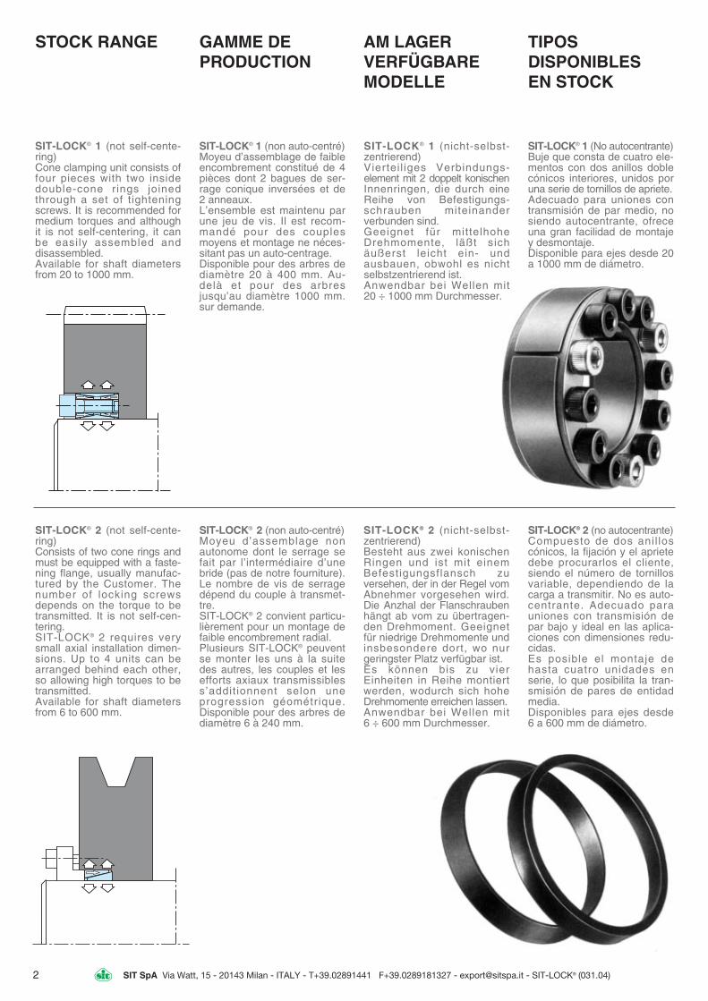
STOCK RANGE
SIT-LOCK® 1 (not self-cente-ring)Cone clamping unit consists offour pieces with two insidedouble-cone rings joinedthrough a set of tighteningscrews. It is recommended formedium torques and althoughit is not self-centering, it canbe easily assembled anddisassembled.Available for shaft diametersfrom 20 to 1000 mm.
TIPOS DISPONIBLES EN STOCK
SIT-LOCK® 1 (No autocentrante)Buje que consta de cuatro ele-mentos con dos anillos doblecónicos interiores, unidos poruna serie de tornillos de apriete.Adecuado para uniones contransmisión de par medio, nosiendo autocentrante, ofreceuna gran facilidad de montajey desmontaje.Disponible para ejes desde 20a 1000 mm de diámetro.
AM LAGERVERFÜGBAREMODELLE
SIT-LOCK® 1 (nicht-selbst-zentrierend)Vierteil iges Verbindungs-element mit 2 doppelt konischenInnenringen, die durch eineReihe von Befestigungs-schrauben miteinanderverbunden sind.Geeignet für mittelhohe Drehmomente, läßt sichäußerst leicht ein- undausbauen, obwohl es nichtselbstzentrierend ist.Anwendbar bei Wellen mit 20 ÷ 1000 mm Durchmesser.
GAMME DE PRODUCTION
SIT-LOCK® 1 (non auto-centré)Moyeu d’assemblage de faibleencombrement constitué de 4pièces dont 2 bagues de ser-rage conique inversées et de2 anneaux.L’ensemble est maintenu parune jeu de vis. Il est recom-mandé pour des couplesmoyens et montage ne néces-sitant pas un auto-centrage.Disponible pour des arbres dediamètre 20 à 400 mm. Au-delà et pour des arbresjusqu’au diamètre 1000 mm.sur demande.
SIT-LOCK® 2 (not self-cente-ring)Consists of two cone rings andmust be equipped with a faste-ning flange, usually manufac-tured by the Customer. Thenumber of locking screwsdepends on the torque to betransmitted. It is not self-cen-tering.SIT-LOCK® 2 requires verysmall axial installation dimen-sions. Up to 4 units can bearranged behind each other,so allowing high torques to betransmitted.Available for shaft diametersfrom 6 to 600 mm.
SIT-LOCK® 2 (non auto-centré)Moyeu d’assemblage nonautonome dont le serrage sefait par l’intermédiaire d’unebride (pas de notre fourniture).Le nombre de vis de serragedépend du couple à transmet-tre.SIT-LOCK® 2 convient particu-lièrement pour un montage defaible encombrement radial.Plusieurs SIT-LOCK® peuventse monter les uns à la suitedes autres, les couples et lesefforts axiaux transmissibless’addit ionnent selon une progression géométrique.Disponible pour des arbres dediamètre 6 à 240 mm.
SIT-LOCK® 2 (nicht-selbst-zentrierend)Besteht aus zwei konischenRingen und ist mit einemBefestigungsflansch zu versehen, der in der Regel vomAbnehmer vorgesehen wird.Die Anzhal der Flanschraubenhängt ab vom zu übertragen-den Drehmoment. Geeignet für niedrige Drehmomente undinsbesondere dort, wo nurgeringster Platz verfügbar ist.Es können bis zu vierEinheiten in Reihe montiertwerden, wodurch sich hoheDrehmomente erreichen lassen.Anwendbar bei Wellen mit 6 ÷ 600 mm Durchmesser.
SIT-LOCK® 2 (no autocentrante)Compuesto de dos anil loscónicos, la fijación y el aprietedebe procurarlos el cliente,siendo el número de tornillosvariable, dependiendo de lacarga a transmitir. No es auto-centrante. Adecuado parauniones con transmisión depar bajo y ideal en las aplica-ciones con dimensiones redu-cidas.Es posible el montaje dehasta cuatro unidades enserie, lo que posibilita la tran-smisión de pares de entidadmedia.Disponibles para ejes desde 6 a 600 mm de diámetro.

3SIT SpA Via Watt, 15 - 20143 Milan - ITALY - T+39.02891441 F+39.0289181327 - [email protected] - SIT-LOCK® (031.04)
SIT-LOCK® 3 (self-centering)Consists of two conical piecesand a spacer. It has minimumoverall dimensions in virtue ofthe reduced thickness of thecones; so, SIT-LOCK® 3 is sui-table for the applications wheresmall hubs are requested.It is recommended for mediumtorques and is self-centering.SIT-LOCK® 3 guarantees avery precise axial positioning,as no any axial displacementof the hub occurs during theassembly operation.Availablefor shaft diameters from 6 to130 mm.
SIT-LOCK® 3 (auto-centré)Constitué de 2 moyeux coni-ques et d’une entretoise.Grâce à son encombrementréduit, le moyeu SIT-LOCK® 3est particulièrement adaptépour le serrage de moyeux àparois minces.Il est recommandé pour descouples moyens et un monta-ge auto-centré.Le SIT-LOCK® 3 garantit unpositionnement très précis, lepréréglage n’est pas modifiépar le serrage. Disponiblepour des arbres de diamètre 6à 90 mm.
SIT-LOCK® 3 (selbstzentrierend)Besteht aus zwei konischenTeilen und einem Distanzring.Es zeichnet sich durch mini-malen Platzbedarf aus, da dieKonusse besonders dünnausgeführt sind,und sichdeshalb für verkleinerteNaben eignen.Geeignet für relativ hoheDrehmomente und selbst-zentrierend. Es entsteht beider Anbringung an der Nabekeinerlei Axialverschiebungzur Welle.Anwendbar bei Wellen mit 6 ÷ 130 mm Durchmesser.
SIT-LOCK® 3 (autocentrante)Compuesto de dos piezascónicas y de un anillo separa-dor. Se caracteriza por unreducido tamaño, siendo tam-bién muy reducido el espesortotal, por lo que resulta idealpara cubos reducidos.Adecuado para uniones contransmisión de par elevado yes autocentrante. Durante elmontaje el cubo no tieneningún desplazamiento axialrespecto al eje.Disponible para ejes desde 6a 130 mm de diámetro.
SIT-LOCK® 4 (self-centering)It is suitable for high torquesand is self-centering.Available for shaft diameterfrom 45 to 600 mm.
SIT-LOCK® 4 (auto-centré)Particulièrement recommandélorsque des couples élevéssont à transmettre, il est auto-centré.Disponible pour des arbres dediamètre 45 à 320 mm.
SIT-LOCK® 4 (selbstzentrierend)Geeignet für hohe Drehmomenteund selbstzentrierend.Anwendbar bei Wellen mit45÷600 mm Durchmesser.
SIT-LOCK® 4 (autocentrante)Adecuado para uniones contransmisión de par muy eleva-do y es autocentrante.Disponible para ejes desde 45 a 600 mm de diámetro.

SIT SpA Via Watt, 15 - 20143 Milan - ITALY - T+39.02891441 F+39.0289181327 - [email protected] - SIT-LOCK® (031.04)
SIT-LOCK® 5A (self-centering)Consists of one inside andone outside cone ring, whichare joined by a set of screws.It is suitable for high torquesand is self-centering.Applications which request avery precise axial positioningare not to do, owing to a smallaxial displacement of the hubduring the assembly operation.Available for shaft diametersfrom 20 to 180 mm.
SIT-LOCK® 5A (auto-centré)Constitué d’une bague coni-que intérieure et d’une bagueconique extérieure assem-blées par un jeu de vis.Il est recommandé pour unecouple élevé, il est auto-cen-tré. Pour des applicationsnécessitant un positionnementaxial précis, SIT-LOCK® 5A nepeut pas convenir en raisond’un léger déplacement axialpossible du moyeu pendantl ’ opé ra t i on de mon tage .Disponible pour des arbres dediamètre 20 à 180 mm.
SIT-LOCK® 5A (selbstzentrierend)Besteht aus einem Innen- undeinem Außenring, die durcheine Reihe von Schraubenmiteinander verbunden sind.Geeignet für besonders hoheDrehmomente und ist selbst-zentrierend. Es erlaubt einehochpräzise Verbindung.Bei der Anbringung enstehtbei der Nabe eine leichteAxialverschiebung zur Welle;deshalb wird dieses Modellnicht für Anwendungsartenempfohlen, die eine strikt gleich-bleibende Axialpositionierungerfordern.Anwendbar bei Wellen mit 20 ÷ 180 mm Durchmesser.
SIT-LOCK® 5A (autocentrante)Compuesto por dos anillos,uno interno y otro externo, uni-dos por una serie de tornillos.Adecuando para uniones contransmisión de par elevado yes autocentrante.Durante el montaje se produ-ce un ligero desplazamientoaxial del cubo sobre el eje, porlo que no está aconsejado enaplicaciones que requieran unposicionamiento axial muypreciso.Disponible para ejes desde 20 a 180 mm.
SIT-LOCK® 5B (self-centering)Consists of one inside andone outside cone ring joinedtogether by means of a set ofscrews and a stop ring.It is recommended for mediumtorques and is self-centering.SIT-LOCK® 5B permits a highprecision axial positioning, asno axial displacement of thehub occurs during the assembly operation.Available for shaft diametersfrom 20 to 180 mm.
SIT-LOCK® 5B (auto-centré)Constitué d’une bague coni-que intérieure et d’une bagueconique extérieure assem-blées par un jeu de vis.Il est recommandé pour unecouple moyen, il est auto-cen-tré.SIT-LOCK® 5B permet unpositionnement axial d’unegrande précision en raison del’impossibilité de déplacementaxial du moyeu pendant l’opé-ration de montage. Disponiblepour des arbres de diamètre20 à 180 mm.
SIT-LOCK® 5B (selbstzentrierend)Besteht aus einem Innen- und einem Außenring, diedurch eine Reihe vonSchrauben und einen Sperringmiteinander verbunden sind.Geeignet für besonders hoheDrehmomente und ist selbst-zentrierend. Besondersgeeignet für Anwendungsarten,die eine strikt gleichbleibendeAxialpositionierung erfordern,da bei der Anbringung keiner-lei Axialverschiebung derNabe gegenüber der Welleensteht.Anwendbar bei Wellen mit 20 ÷ 180 mm. Durchmesser.
SIT-LOCK® 5B (autocentrante)Compuesto por dos anillos,uno interno y otro externo,unidos por una serie de tornil-los asi como de un anil loseparador.Adecuado para uniones contransmisión de par elevado yes autocentrante. Esta espe-cialmente indicado, paraaquellas aplicaciones dondese requiera un preciso posi-cionamiento axial, ya quedurante el montaje, no existeningún deslizamiento entre ejey cubo.Disponible para ejes desde20 a 180 mm.
4
SIT SpA Via Watt, 15 - 20143 Milan - ITALY - T+39.02891441 F+39.0289181327 - [email protected] - SIT-LOCK® (031.04)
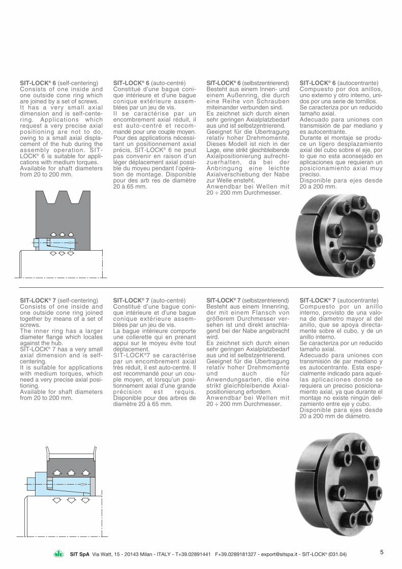
SIT-LOCK® 6 (self-centering)Consists of one inside andone outside cone ring whichare joined by a set of screws.It has a very small axialdimension and is self-cente-ring. Applications whichrequest a very precise axialposit ioning are not to do,owing to a small axial displa-cement of the hub during theassembly operation. SIT-LOCK® 6 is suitable for appli-cations with medium torques.Available for shaft diametersfrom 20 to 200 mm.
SIT-LOCK® 6 (auto-centré)Constitué d’une bague coni-que intérieure et d’une bagueconique extérieure assem-blées par un jeu de vis.I l se caractérise par unencombrement axial réduit, ilest auto-centré et recom-mandé pour une couple moyen.Pour des applications nécessi-tant un positionnement axialprécis, SIT-LOCK® 6 ne peutpas convenir en raison d’unléger déplacement axial possi-ble du moyeu pendant l’opéra-tion de montage. Disponiblepour des arb res de diamètre20 à 65 mm.
SIT-LOCK® 6 (selbstzentrierend)Besteht aus einem Innen- undeinem Außenring, die durcheine Reihe von Schraubenmiteinander verbunden sind.Es zeichnet sich durch einensehr geringen Axialplatzbedarfaus und ist selbstzentrierend.Geeignet für die Übertragungrelativ hoher Drehmomente.Dieses Modell ist nich in derLage, eine strikt gleichbleibendeAxialpositionierung aufrecht-zuerhalten, da bei derAnbringung eine leichteAxialverschiebung der Nabezur Welle ensteht.Anwendbar bei Wellen mit 20 ÷ 200 mm Durchmesser.
SIT-LOCK® 6 (autocentrante)Compuesto por dos anillos,uno externo y otro interno, uni-dos por una serie de tornillos.Se caracteriza por un reducidotamaño axial.Adecuado para uniones contransmisión de par mediano yes autocentrante.Durante el montaje se produ-ce un ligero desplazamientoaxial del cubo sobre el eje, porlo que no esta aconsejado enaplicaciones que requieran unposicionamiento axial muypreciso.Disponible para ejes desde 20 a 200 mm.
SIT-LOCK® 7 (self-centering)Consists of one inside andone outside cone ring joinedtogether by means of a set ofscrews.The inner ring has a largerdiameter flange which locatesagainst the hub.SIT-LOCK® 7 has a very smallaxial dimension and is self-centering.It is suitable for applicationswith medium torques, whichneed a very precise axial posi-tioning.Available for shaft diametersfrom 20 to 200 mm.
SIT-LOCK® 7 (auto-centré)Constitué d’une bague coni-que intérieure et d’une bagueconique extérieure assem-blées par un jeu de vis.La bague intérieure comporteune collerette qui en prenantappui sur le moyeu évite toutdéplacement.SIT-LOCK®7 se caractérisepar un encombrement axialtrès réduit, il est auto-centré. Ilest recommandé pour un cou-ple moyen, et lorsqu’un posi-tionnement axial d’une grandeprécision est requis.Disponible pour des arbres dediamètre 20 à 65 mm.
SIT-LOCK® 7 (selbstzentrierend)Besteht aus einem Innenring,der mit einem Flansch vongrößerem Durchmesser ver-sehen ist und direkt anschla-gend bei der Nabe angebrachtwird.Es zeichnet sich durch einensehr geringen Axialplatzbedarfaus und ist selbstzentrierend.Geeignet für die Übertragungrelativ hoher Drehmomenteund auch fürAnwendungsarten, die einestrikt gleichbleibende Axial- positionierung erfordern.Anwendbar bei Wellen mit 20 ÷ 200 mm Durchmesser.
SIT-LOCK® 7 (autocentrante)Compuesto por un anil lo interno, provisto de una valo-na de diametro mayor al delanillo, que se apoya directa-mente sobre el cubo, y de unanillo interno.Se caracteriza por un reducidotamaño axial.Adecuado para uniones contransmisión de par mediano yes autocentrante. Esta espe-cialmente indicado para aquel-las aplicaciones donde serequiera un preciso posiciona-miento axial, ya que durante elmontaje no existe ningún deli-zamiento entre eje y cubo.Disponible para ejes desde 20 a 200 mm de diámetro.
5

SIT SpA Via Watt, 15 - 20143 Milan - ITALY - T+39.02891441 F+39.0289181327 - [email protected] - SIT-LOCK® (031.04)
SIT-LOCK® 8 (self-centering)Consists of one inside andone outside cone ring joinedtogheter by means of a set ofscrews. The inner ring has alarger diameter flange whichlocates against the hub.SIT-LOCK® 8 has a very smallaxial dimension and is self-centering. It has been desi-gned to suit various shaft dia-meters although the overalldimensions are the same.SIT-LOCK® 8 is recommendedfor applications with mediumtorques which need a veryprecise axial positioning.Available for shaft diametersfrom 14 to 50 mm.
SIT-LOCK® 8 (auto-centré)Constitué d’une bague coni-que intérieure et d’une bagueconique extérieure assem-blées par un jeu de vis.La bague intérieure comporteune collerette qui en prenantappui sur le moyeu évite toutdéplacement.SIT-LOCK® 8 se caractérisepar un encombrement axialtrès réduit, il est auto-centré.Pour un diamètre extérieuridentique, il offre une impor-tante gamme d’alésages.SIT-LOCK® 8 est recommandépour un couple moyen, et lor-squ’un positionnement axiald’une grande précision estrequis. Disponible pour desarbres de diamètre 14 à 50 mm.
SIT-LOCK® 8 (selbstzentrierend)Besteht aus zwei konischenRingen, die durch eine Reihevon Schrauben miteinanderverbunden sind, wobei derInnenring mit einem Flanschvon größerem Durchmesserversehen ist, welcher direktanschlagend bei der Nabeangebracht wird.Es zeichnet sich durch einensehr geringen Axialplatzbedarfaus und ist selbstzentrierend.Bei gleichbleibendem Außen-durchmesser ist dieses Modellmit verschiedenen Wellen-Innendurchmessern erhältlich.Geeignet für die Übertragungrelativ hoher Drehmomente undauch für Anwendungsarten,die eine präzise Axial-positionierung erfordern.Anwendbar bei Wellen mit 14 ÷ 50 mm Durchmesser.
SIT-LOCK® 8 (autocentrante)Compuesto por un anillo inter-no, provisto de una valona dediámetro mayor al del anilloque se apoya directamentesobre el cubo, y de un anilloexterno.Adecuado para uniones contransmisión de par medio y esautocentrante. De caracteristi-cas muy semejantes al SIT-LOCK® 7, se diferencia de estepor tener solo cuatro gruposde diámetros exteriores, enlos que se agrupan todos losdiámetros de eje.Disponible para ejes desde 14 a 50 mm de diámetro.
SIT-LOCK® 9 (not self-cente-ring)Consists of two cone rings, joi-ned through a lock nut and atab washer.In virtue of the simple design,very fast assembly/disassem-bly is allowed. SIT-LOCK® 9 issuitable for applications withsmall-medium torques.Available for shaft diametersfrom 14 to 70 mm.
SIT-LOCK® 9 (non auto-centré)Constitué de 2 bagues coni-ques maintenues par un écroude serrage et d’une rondellede sécurité. Il se caractérisepar une grande rapidité demontage et démontage.SIT-LOCK® 9 est recommandépour une couple faible/moyen.Disponible pour des arbres dediamètre 14 à 70 mm.
SIT-LOCK® 9 (nicht selbst-zentrierend)Besteht aus zwei konischenRingen, einer Befestigungs-Ringmutter und einer Sicherheits-Zwischenscheibe.Das Modell zeichnet sich ausdurch sehr schnellen Ein- undAusbau.Es wird für Anwendungen mitmittelhohen bis kleinenDrehmomenten empfohlen.Anwendbar bei Wellen mit 14 ÷ 70 mm Durchmesser.
SIT-LOCK® 9 (no autocentrante)Compuesto por dos anilloscónicos y una arandela deseguridad, se caracteriza porla rapidez de montaje-desmontaje.Adecuado para uniones contransmisión de par medio-bajo.Disponible para ejes desde 14 a 70 mm de diámetro.
6

SIT SpA Via Watt, 15 - 20143 Milan - ITALY - T+39.02891441 F+39.0289181327 - [email protected] - SIT-LOCK® (031.04)
SPECIAL TYPESAVAILABLE ONREQUEST
In addition to the 10 stocktypes, SIT manufactures alsospecial items on request.Some examples of the mostcommon special items aredescribed hereunder.
SIT-LOCK® 10SRigid coupling for variousapplications. Available forshaft diameter from 17 to 80mm.
SIT-LOCK® 11SSelf-locking unit suitable for hol-low shafts.It transmits high torques. SIT-LOCK® 11S is available for shaftdiameter from 24 to 500 mm.
SIT-LOCK® 12SSIT-LOCK®12S is self-cente-ring unit.It is suggested, only for bigquantities, in the applicationswith medium torques.
SIT-LOCK® 13SSIT-LOCK®13S is very closeto the standard type SIT-LOCK® 9, but it is manufactu-red in a longer execution.
MODÈLES SPÉ-CIAUX DISPONI-BLES SURDEMANDE
SIT peut livrer sur demande enplus des 10 modèles tenushabituellement sur stock, desmoyeux d’assemblage en exé-cution spéciale. Nous vous pré-sentons ci-dessous quelquesexemples de nos possibilités.
SIT-LOCK® 10SAccouplement rigide, applica-tion diverses.Possible pour des diamètresde 17 à 80 mm.
SIT-LOCK® 11SMoyeux d’assemblages pourarbres creux, couple transmis-sible élevé.Possible pour des diamètresde 24 à 500 mm.
SIT-LOCK®12SLe moyeu SIT-LOCK® 12S estun système auto-centré.Il répond aux installations aveccouple moyen et sera proposéseulement dans des applica-tions de grande série.
SIT-LOCK® 13SLe moyeu SIT-LOCK® 13S estde fabrication identique autype SIT-LOCK® 9, mais enexécution moyeux longs.
S O N D E R A U S -FÜHRUNGEN AUFANFRAGE ERHÄLTLICH
Auf Anfrage stellt die Firma SITaußer den zehn ab Lagerverfügbaren Typen auchSonderausführungen her. Hierunten können Sie einigeBeispiele der häufigstenSonderausführungen finden.
SIT-LOCK® 10SStarre Kupplung für verschiedeneAnwendungen. Anwendbar bei Wellen mit 17 ÷ 80 mm Durchmesser.
SIT-LOCK® 11SSpannsatz für Hohlwellen. Erüberträgt hohe Drehmomente.Anwendbar bei Wellen mit 24 ÷ 500 mm Durchmesser.
SIT-LOCK® 12SS e l b s t z e n t r i e r e n d e rSpannsatz. Dieses Modell istfür mittelhohe Drehmomentegeeignet und es wird nur ingroßen Mengen hergestellt.
SIT-LOCK® 13SDieses Modell ist demStandard SIT-LOCK® 9 ähnlich,ist aber länger.
MODELOS ESPECIALESBAJO PEDIDO
SIT fabrica, bajo pedido, tiposespeciales, además de los 10tipos en stock.A continuación mostramosalgunos de los tipos especia-les más comunes.
SIT-LOCK® 10SUnión rígida para aplicacionesvarias.Ej. Acoplamiento rígido de ejes.Disponible para ejes desde 17a 80 mm de diámetro.
SIT-LOCK® 11SElevado par transmisible.Disponible para ejes desde 24a 500 mm de diámetro.
SIT-LOCK® 12SUniones autocentrantes, acon-sejadas para series grandes.
SIT-LOCK®13SUniones similares al tipo stan-dart SIT-LOCK® 9, pero en eje-cución mas larga.
7

SIT SpA Via Watt, 15 - 20143 Milan - ITALY - T+39.02891441 F+39.0289181327 - [email protected] - SIT-LOCK® (031.04)
INSTRUCTIONS FOR USE
SIT-LOCK® hub boreWith the superior holdingpower of the SIT-LOCK® desi-gn, bore diameters can beproduced by simple turning.Precision machining is notnecessary.
RoughnessA lathe tool surface finishingallows SIT-LOCK® to carry outits duties. Recommendedroughness values:Rt = 16 µm (for SIT-LOCK® 2:Rt = 6 µm).
TolerancesSIT-LOCK® seats do not requi-re precision tolerances.We suggest the following fits:- h8 for the shaft;- H8 for the hub.
ConcentricitySIT-LOCK® 1, 2 and 9 have nocentring effect. For this rea-son, the running accuracydepends on the matchingbetween shaft and hub bore.SIT-LOCK® 3 to SIT-LOCK® 8are self-centering. In this casethe clamping element has acentring effect and the con-centricity error can be consi-dered to 0,02-0,04 mm.By performing a centring guidebetween shaft and hub therunning accuracy can beimproved.
INSTRUCTIONS DE MONTAGE
Alésage du moyeuLes alésages sont à réalisersur des machines standards(tours).La finition de l’alésage doitrespecter l’état de surface sui-vant:Rt = 16 µm (pour SIT-LOCK® 2:Rt = 6 µm).
Tolérances- h8 pour l’arbre;- H8 pour l’alésage du moyeu.
ConcentricitéLes moyeux d’assemblageSIT-LOCK® 1, 2 et 9 ne sontpas auto-centrés. Pour cetteraison la qualité de l’assem-blage dépend de l’ajustemententre l’arbre et l’alésage dumoyeu.Les moyeux d’assemblageSIT-LOCK® 3 à 8 sont auto-centrés. Dans ce cas, suivantles diamètres, le défaut deconcentricité admissible est de0,02 à 0,04 mm. Avec un cen-trage supplémentaire entrel’arbre et l’alésage les perfor-mances du montage sontaméliorées.
HINWEISE ZUMGEBRAUCH
Anbringungssitze für SIT-LOCK®
Die Sitze für die SIT-LOCK®
Teile werden mit einer einfa-chen Drehbankbearbeitungausgeführt, da sie keine spe-zielle geometrische Formaufweisen müssen.
OberflächenrauheitEine gut Oberflächenbearbeitungan der Drehbank reicht aus, umdie sachgerechte Funktion-stüchtigkeit der Teile zu gewähr-leisten. Es wird empfohlen, einenWert von Rt = 16 µm nicht zuüberschreiten, bzw. von Rt = 6µm beim Modell SIT-LOCK® 2.
ToleranzbereichDie Einhaltung eines engenToleranzbereichs für die SIT-LOCK® Sitze ist nicht erforder-lich. Als Richtlinie werden diefolgenden Werte empfohlen:- Welle h8; - Nabe H8.Ausführlichere Angaben findenSie auf den Abmessungstabellen.
KonzentrizitätDie Modelle SIT-LOCK® 1, 2 und 9sind nicht selbstzentrierend.Dementsprechend hängt die fürsie erreichbare Konzentrizität vonder Bearbeitungsqualität und vonder Länge der Zentrierführung ab.Die übrigen SIT-LOCK® Modellesind selbstzentrierend. Bei ihnenläßt sich der Konzentrizitätsfehlerzwischen 0,02 und 0,04 mm lie-gend ansetzen. Die Konzentrizitätkann noch weiter erhöht werden,indem man eine Zentrierführungzwischen Welle und Nabe anbringt.
NORMAS DE UTILIZACION
Alojamiento para SIT-LOCK®
El alojamiento se obtienemediante una simple opera-ción de torneado.
RugosidadUn buen acabado de torno essuficiente para asegurar unfuncionamiento correcto. Seaconseja no superar el valorRt = 16 µm (Rt = 6 µm para eltipo 2).
ToleranciasLas uniones SIT-LOCK® norequieren tolerancias muyestrechas para el alojamiento.Sugerimos: - h8 para eje;- H8 para cubo.Ver tablas de dimensionespara los distintos tipos.
ConcentricidadLos tipos 1, 2 y 9 no son auto-centrantes, por lo tanto la con-centricidad estará en funciónde la calidad del mecanizadoy de la longitud de la guia decentraje.Los otros tipos si son autocen-trantes. En este caso el error deconcentricidad se puede consi-derar entre 0,02 - 0,04 mm.La concentricidad puedemejorarse mediante una guiaentre el eje y el cubo.
ASSEMBLYa) Clean with care the area ofcontact of shaft and hub. Thenlightly oil both surfaces withstandard mineral oil.WARNING: do not use specialoils with molibdenum bisulphi-de or other substances whichcould reduce drastically thefriction coefficient.Note: the transmissible torque and axial forcevalues stated in this catalogue are valid for alubricated assembly (µ=0,12).
b) Position the SIT-LOCK® inthe machined bore of the hub.c) Insert the shaft.d) Gradually and uniformlytighten the clamping screwsup to the tightening torque Msstated in the catalogue. Thisoperation must be done tighte-ning diagonally oppositescrews in stages.Note: in case of SIT-LOCK® 9 -which has a locknut instead of the clamping screws - the tighte-ning torque Ms must be applied to the lock nut.
MONTAGEa) Nettoyer avec attentionl’alésage du moyeu et l’arbre.Huiler légèrement les 2 surfa-ces avec de l’huile minérale.ATTENTION: Ne pas utiliserdes huiles spécif iques aubisulfure de molybdène.Remarque: les couples transmissibles et lesvaleurs des charges axiales indiqués dans lecatalogue tiennent compte d’un montageavec lubrification (µ=0,12).
b)Positionner le moyeu d’as-semblage SIT-LOCK® dansl’alésage du moyeu de lapièce à assembler.c)Monter l’ensemble sur l’arbre.d)Visser et serrer progressive-ment les vis de serragejusqu’au couple de serrageMs indiqué dans le catalogue.Cette opération doit être réali-sée par un serrage en diago-nale des vis du moyeu d’as-semblage.Remarque: Dans le cas du SIT-LOCK® 9, lecouple de serrage doit être appliqué sur l’écrou.
EINBAUa) Die Wellenoberfläche und denSitz des SIT-LOCK® Elementssorgfältig säubern und mit einemdünnen Schmierölfilm versehen.ACHTUNG: Auf keinen FallMolybdänbisulfid oder andereSubstanzen verwenden, die eineerhebliche Senkung desReibungskoeffizienten bewirken.Anmerkung: Die in den beiliegenden Tabellengenannten übertragbaren Drehmomentswerteund Axialkraftwerte beziehen sich auf geschmiertmontierte Teile (µ=0,12).
b)Das SIT-LOCK® in den in derNabe angefertigten Sitz fügen.c)Die Welle einsetzen.d)Die Befestigungsschraubenschrittweise und gleichmäßig nachdem Kreuzschema festziehen, bisdas in den beiliegenden Tabellengenannte Festzieh-DrehmomentswertDrehmomentswert Ms erreicht ist.Anmerkung: Das Modell SIT-LOCK® 9, ist nicht mitSchrauben, sondern mit einer Befestigungs-Ringmutterversehen, weshalb der in der Tabelle genannte Ms-Drehmomentswert auf die Ringmutter anzuwenden ist.
MONTAJEa) Limpiar cuidadosamentelas superficies de contacto deeje y cubo y aplicar una finapelícula de aceite.ATENCION: no utilizar bisulfu-ro de molibdeno o cualquierproducto que reduzca el coefi-ciente de fricción.Nota: El par transmisible y la carga axial indi-cadas en la tabla se refieren a un montajecon lubrificación.
b)Colocar el SIT-LOCK® en elalojamiento del cubo.c)Introducir el conjunto en el eje.d)Apretar gradual y uniforme-mente todos los tornillos, enpares opuestos 180°, hastaalcanzar el valor de par deapriete Ms indicado en latabla.Nota: en el caso del SIT-LOCK® 9, provisto deun aro de apriete, en vez de tornillos, debeaplicarse a este aro el valor Ms de par deapriete.
8

SIT SpA Via Watt, 15 - 20143 Milan - ITALY - T+39.02891441 F+39.0289181327 - [email protected] - SIT-LOCK® (031.04)
DISASSEMBLY
DESIGN PROCEDURE MÉTHODE DE CALCUL RECHENMETHODE CÁLCULO
DÉMONTAGE AUSBAU DESMONTAJE
The disassembly procedurevaries lightly depending on theSIT-LOCK® type.1)SIT-LOCK® 1 and SIT-LOCK® 2
Gradually loosen opposite clamping screws in stages untilthe SIT-LOCK® is released. In case it should remain jammed,it is necessary to hammer lightly the released screws, so that the back cone ring ispushed backwards.
2) SIT-LOCK® 9Loosen the lock nut until theSIT-LOCK® is completely released.
3) SIT-LOCK® 3, 5, 6, 7 & 8a)Loosen the clamping screws.b)Transfer the screws into the
releasing tapped holes and tighten them until the SIT-LOCK® is released.
4) SIT-LOCK® 4a)Loosen the clamping screws.b)Transfer the screws into the
releasing tapped holes and tighten them until the front cone is released.
c)Loosen the clamping screws.d)Transfer the clamping screws
into the releasing holes of theintermediate ring, and tightenthem until the back cone is released.
Les procédures de démontagevarient suivant le type desmoyeux d’assemblage.1) SIT-LOCK® 1 et SIT-LOCK® 2
Dévisser progressivement lesvis diamètralement opposées.Le moyeu d’assemblage doit se désaccoupler. Dans le cas contraire, il faut marteler légè-rement les vis de serrage déjà dévissées.
2) SIT-LOCK® 9Dévisser l’écrou jusqu’au démontage du moyeu d’as-semblage.
3) SIT-LOCK® 3, 5, 6, 7 & 8a) Dévisser les vis de serrage.b) Monter les vis de serrage
dans les trous d’extraction, puis visser jusqu’au démonta-ge du moyeu d’assemblage.
4) SIT-LOCK® 4a) Dévisser les vis de serrage.b) Monter les vis de serrage
dans les trous d’extraction et visser jusqu’au démontage ducône.
c) Dévisser les vis de serrage.d) Monter les vis de serrage
dans les trous d’extraction situés dans la bague intermé-diaire, puis visser jusqu’au démontage du cône arrière.
Die Vorgehensweise für denAusbau der Teile unterschei-det sich leicht je nach SIT-LOCK® Modell.1)SIT-LOCK® 1 und 2
Die Befestigungschrauben stu-fenweise lockern, bis sich das SIT-LOCK® löst. Sollte es blockiert bleiben, geben Sieleichte Hammerschläge auf dieblockierten Befestigungssch-rauben:Hierdurch wird der hintere Druckkonus zurückversetzt.
2)SIT-LOCK® 9Die Befestigungs-Ringmutterlockern, bis sich das SIT-LOCK®
vollständig löst.3)SIT-LOCK® 3, 5, 6, 7 & 8a)Die Befestigungsschrauben
lockern.b)Die Befestigungsschrauben
entfernen und in die Ausstoßbohrungen einschrauben,bis sich der hintere Konus löst.
4)SIT-LOCK® 4a)Die Befestigungsschrauben
lockern.b)Die Befestigungsschrauben
entfernen und in die Ausstoßbohrungen einschrauben,bis sich der vordere Konus löst.
c)Die Befestigungsschrauben lockern.
d)Die Befestigungsschrauben entfernen und in den mittlerenRing einschrauben, bis sich der hintere Konus löst.
El procedimiento de desmon-taje tiene algunas diferenciasdependiendo del t ipo SIT-LOCK® que utilicemos.1)SIT-LOCK® 1 y 2
Aflojar los tornillos opuestosgradualmente hasta obtenerel desbloqueo del anillo. En el caso de que quedase blo-queado, daremos unos lige-ros golpes con un martillo de plástico a los tornillos de apriete bloqueados; de este modo liberaremos el cono de presión posterior.
2) SIT-LOCK® 9Aflojar el aro de apriete hastaconseguir el desbloqueo delanillo.
3)SIT-LOCK® 3, 5, 6, 7 & 8a)Aflojar los tornillos de aprieteb)Retirarlos y colocarlos en los
alojamientos de desmontaje,apretando hasta desbloquearel cono posterior.
4)SIT-LOCK® 4a)Aflojar los tornillos de apriete.b)Retirarlos y colocarlos en los
alojamientos de desmontaje,apretando hasta desbloquearel cono anterior.
c)Afloiar otra vez los tornillos de apriete.
d)Retirarlos y colocarlos en losalojamientos del anillo inter-medio, apretando hasta desbloquear el cono posterior.
For a proper functioning of SIT-LOCK®, the transmissible torqueMt (stated in this catalogue)must be always bigger than themaximum torque in operation.So, in the selection of the SIT-LOCK® dimensions, it must beconsidered that the start up tor-que could be even 4 times big-ger than the nominal one. Thetransmissible axial forces (Pax)given in the tables are valid forthe case where no torqueoccurs. If it should be necessaryto transmit both a torque and anaxial force (ex. helical gear) thefollowing formula must be used:
Pour un dimensionnement cor-rect d’un moyeu d’assemblageSIT-LOCK®, la couple transmis-sible Mt doit toujours être supé-rieur au couple absorbé par l’ap-plication. Ainsi pour sélectionnerun moyeu d’assemblage il fautconsidérer que le couple dedémarrage peut être 4 fois plusimportant que le couple nominal.Les valeurs des forces axialesindiquées dans le tableaux sontuniquement valables lorsqu’il n’ya pas de couple à transmettre.Si un couple et une charge axia-le sont appliqués au niveau dumoyeu d’assemblage (pignonsconiques, par exemple), il faututiliser la formule suivante:
Um eine einwandfreie Funktion-stüchtigkeit der SIT-LOCK®-Verbindungen zu gewährleisten, istsicherzustellen, daß der übertrag-bare Drehmomentswert Mt (in denTabellen aufgeführt) stets höher istals das maximale beim Betriebentstehende Drehmoment. Hierbeiist zu berücksichtigen, daß dieDrehmomentswerte beim Anlaufvon Elektromotoren bis zu viermalso hoch sind wie die bei der vollenLaufdrehzahl entstehenden. Die inden Tabellen genannten Werte zurübertragbaren Axialkraft (Pax) sindnur gültig bei mangelnden zu über-tragenden Drehmomenten. Solltensowohl ein Drehmoment als aucheine Axialkraft übertragen werden(z.B. bei Schrägzahnrädern, ist diefolgende Formal anzuwenden:
Para una aplicación satisfactoriaes imprescindible que el partransmisible que figura en latabla Mt, sea superior al parmáximo durante el trabajo.Téngase en cuenta que, duran-te el arranque, los motores eléc-tricos convencionales puedengenerar un valor del par hasta 4veces el par nominal.El valor de carga axial (Pax) dela tabla es válido en el caso queel par a transmitir sea nulo.En caso de transmitir tantocarga axial como par (ej. engra-najes helicoidales), debe cum-plirse la siguiente formula:
where:Ma = maximum torque to be tran-smitted [daNm]Fa = axial force in operation [daN]d = shaft diameter [mm]
avec:Ma = couple max. à transmettre[daNm]Fa = force axiale [daN]d = diamètre de l’arbre [mm]
wobei sind:Ma = Größtes zu übertragendesDrehmoment [daNm]Fa = Axialkraft beim Betrieb [daN]d = Wellendurchmesser [mm]
siendo:Ma = Par máximo a transmitir[daNm]Fa = Fuerza axial a transmitir[daN]d = Diámetro del eje [mm]
9

SIT SpA Via Watt, 15 - 20143 Milan - ITALY - T+39.02891441 F+39.0289181327 - [email protected] - SIT-LOCK® (031.04)
Table 1 - Tableau 1 - Tabelle 1 - Tabla 1
DESIGN OF HUBOUTSIDE MINI-MUM DIAMETER
CALCUL DUDIAMÉTRE EXTE-RIEUR MINIMUMDU MOYEU
BERECHNUNGDES NABEN-MINDEST-DURCHMESSERS
CÁLCULO DELDIÁMETROMÍNIMO DELCUBO
Using the self-locking units,the shaft-hub connection ischaracterized by a pressureon the hub surface, which isexerted by the self-locking unitouter ring when the clampingscrews are tightened to thestated value. So, it is impor-tant to design correctly thehub outside diameter. The fol-lowing table summarizes theprocedure as a simple calcula-tion, to determine the hub out-side minimum diameter, sim-ply multiply the factor K by theSIT-LOCK® outside diameterto obtain the hub outside mini-mum diameter. The factor Kvaries depending on the fol-lowing variables: - yield limit of hub material; - hub surface pressure (Pn): - factor (x), variable according
to the application type (A, B, C).
Le montage du moyeu d’as-semblage sur l ’arbre oc-casionne lors du serrage desvis une pression sur la surfaceintérieure de l ’alésage dumoyeu de la pièce à assem-bler. Par conséquent il estimportant de calculer lediamètre extérieur du moyeu àassembler. Le tableau suivantrésume la méthode pourdéterminer celui-ci le Dia. min.du moyeu = D x K, avec D:diamètre du moyeu d’assem-blage. Le facteur K dépenddes éléments suivants: - limite élastique du matériau; - pression Pn dans l’alésage du moyeu;
- facteur X variable suivant lescas de montage A, B et C.
Die Verbindung von Welle undNabe über Spannelemente wirddurch eine auf die Nabeausgeübte Oberflächenbe-lastung gekennzeichnet, diedurch den Druck desSpannelemente-Außenringsbewirkt wird, welcher beimAnziehen der Befestigungs-sch-rauben mit dem festgelegtenDrehmomentswert entsteht.Unter diesen Bedingungen istdie Nabe zu bemessen, als obes sich bei ihr um einen sehrdickwandigen Hohlzylinderhandeln würde. Um diesesVerfahren in einer einfachenRechnung anwenden zu kön-nen, liefern wir nachfolgendeine Tabelle, und der Faktor(K), mit welchem derAußendurchmesser des SIT-LOCK® zu multiplizieren ist,um den Mindestdurchmesserder Nabe zu erhalten. DieserFaktor ist abhängig von derStreckgrenze des Naben-materials, vom auf die Nabeausgeübten Durck (Pn) undvon einem Koeffizienten (X),der je nach Montageart (A, B,oder C) schwankt.
Las uniones eje-cubo median-te bujes cónicos de fijación secaracterizan por la solicitacióndel cubo debido a la presiónque ejerce el anillo exterior alapretar los tornillos a los valo-res de las tablas. Debe, portanto, dimensionarse conve-nientemente el espesor de lapared del cubo. Para simplifi-car el cálculo del espesor seutiliza la tabla siguiente, y elfactor K, que debemos multi-plicar por el diámetro exteriordel buje, para obtener el diá-metro mínimo del cubo. El fac-tor K esta definido por: - las características del mate-
rial del cubo; - la presión generada sobre el
cubo (Pn); - un coeficiente X que varia
según el tipo de montaje.
Application AMontage AMontageart AMontaje tipo A
Application BMontage BMontageart BMontaje tipo B
Application CMontage CMontageart CMontaje tipo C
Dn D • K [mm]
(with
out c
entr
ing
guid
e)(s
ans
base
de
cent
rage
)(o
hne
zent
riers
itz)
(sin
bas
e de
cen
trad
ura)
(with
out c
entr
ing
guid
e)(s
ans
base
de
cent
rage
)(o
hne
zent
riers
itz)
(sin
bas
e de
cen
trad
ura)
(in s
erie
with
cen
tring
gui
de)
(en
serie
ave
c ba
se d
e ce
ntra
ge)
(Ser
ienm
äßig
mit
zent
riers
itz)
(en
la s
erie
con
bas
e de
cen
tradu
ra)
10
X = 1
X = 0,8
X = 0,6
K =σn02 + (x • Pn)
K = σn02 – (x • Pn)�����
H
Dn
2 • H
Dn
2 • H
Dn
σn 02 [daN/mm2] = Yield limit of
hub material
Limite élastique svivante matiéredu moyeu
Streckgrenze des Nabenmaterials
Limite elastico del material delcubo
Pn [daN/mm2] = Hub surfacepressure
Pression supercicielle dans l’ále-sage
Auf Nabe ausgeübter Druck
Presión sobre el cubo
C 1,29 1,26 1,21 1,19 1,16 1,15 1,13 1,11 1,10 1,09 1,076 B 1,40 1,31 1,25 1,24 1,23 1,21 1,19 1,16 1,13 1,12 1,09
A 1,53 1,43 1,37 1,33 1,29 1,26 1,23 1,19 1,17 1,15 1,11
C 1,31 1,26 1,23 1,21 1,19 1,16 1,14 1,12 1,11 1,10 1,086,5 B 1,45 1,36 1,31 1,29 1,25 1,23 1,21 1,17 1,15 1,13 1,10
A 1,61 1,46 1,41 1,36 1,31 1,29 1,25 1,21 1,19 1,17 1,13
C 1,35 1,27 1,25 1,23 1,19 1,17 1,16 1,13 1,12 1,11 1,087 B 1,49 1,39 1,35 1,31 1,26 1,24 1,21 1,19 1,16 1,14 1,11
A 1,66 1,51 1,46 1,41 1,35 1,31 1,26 1,23 1,21 1,18 1,14
C 1,31 1,29 1,26 1,24 1,21 1,19 1,16 1,15 1,13 1,12 1,097,5 B 1,53 1,43 1,37 1,33 1,29 1,26 1,23 1,19 1,17 1,15 1,12
A 1,75 1,56 1,49 1,43 1,37 1,34 1,31 1,26 1,21 1,19 1,14
C 1,40 1,32 1,29 1,26 1,22 1,21 1,19 1,16 1,14 1,12 1,098 B 1,59 1,46 1,40 1,36 1,31 1,28 1,25 1,21 1,19 1,16 1,12
A 1,82 1,62 1,54 1,47 1,40 1,37 1,32 1,27 1,23 1,21 1,15
C 1,43 1,35 1,31 1,28 1,24 1,22 1,20 1,17 1,15 1,13 1,108,5 B 1,64 1,50 1,43 1,39 1,33 1,30 1,27 1,23 1,20 1,17 1,13
A 1,91 1,68 1,58 1,51 1,43 1,40 1,35 1,29 1,25 1,22 1,16
C 1,47 1,37 1,33 1,29 1,26 1,23 1,21 1,18 1,16 1,14 1,109 B 1,70 1,54 1,47 1,41 1,35 1,32 1,29 1,24 1,21 1,19 1,14
A 2,01 1,74 1,63 1,55 1,47 1,42 1,37 1,31 1,27 1,23 1,17
C 1,50 1,40 1,35 1,31 1,27 1,25 1,22 1,19 1,16 1,15 1,119,5 B 1,76 1,58 1,50 1,44 1,38 1,35 1,31 1,26 1,22 1,20 1,15
A 2,12 1,81 1,69 1,60 1,50 1,45 1,40 1,33 1,28 1,25 1,18
C 1,54 1,42 1,37 1,33 1,29 1,26 1,23 1,20 1,17 1,15 1,1210 B 1,82 1,62 1,54 1,47 1,40 1,37 1,32 1,27 1,23 1,21 1,15
A 2,25 1,88 1,74 1,64 1,54 1,49 1,42 1,35 1,30 1,26 1,19
C 1,57 1,45 1,40 1,35 1,30 1,28 1,25 1,21 1,18 1,16 1,1210,5 B 1,89 1,67 1,57 1,51 1,43 1,39 1,34 1,29 1,25 1,22 1,16
A 2,39 1,96 1,80 1,69 1,57 1,52 1,45 1,37 1,32 1,28 1,20
C 1,61 1,48 1,42 1,37 1,32 1,29 1,26 1,22 1,19 1,17 1,1311 B 1,97 1,72 1,61 1,54 1,45 1,41 1,36 1,30 1,26 1,23 1,17
A 2,56 2,05 1,87 1,74 1,61 1,55 1,48 1,39 1,34 1,29 1,21
C 1,65 1,51 1,44 1,37 1,34 1,31 1,27 1,23 1,20 1,18 1,1311,5 B 2,05 1,77 1,65 1,57 1,48 1,44 1,38 1,32 1,27 1,24 1,18
A 2,76 2,14 1,94 1,80 1,65 1,59 1,51 1,42 1,35 1,31 1,22
C 1,70 1,54 1,47 1,40 1,35 1,32 1,29 1,24 1,21 1,19 1,1412 B 2,14 1,82 1,70 1,61 1,51 1,46 1,40 1,34 1,29 1,25 1,19
A 3,01 2,25 2,01 1,85 1,70 1,62 1,54 1,44 1,37 1,32 1,23
C 1,74 1,57 1,49 1,44 1,37 1,34 1,30 1,25 1,22 1,19 1,1412,5 B 2,25 1,88 1,74 1,64 1,54 1,49 1,42 1,35 1,30 1,26 1,19
A 3,33 2,36 2,09 1,92 1,74 1,66 1,57 1,46 1,39 1,34 1,25
C 1,79 1,60 1,52 1,46 1,39 1,36 1,31 1,26 1,23 1,20 1,1513 B 2,36 1,94 1,79 1,68 1,57 1,51 1,45 1,37 1,31 1,28 1,20
A 3,75 2,50 2,18 1,98 1,79 1,70 1,60 1,49 1,41 1,36 1,26
C 1,84 1,62 1,55 1,48 1,41 1,37 1,33 1,28 1,24 1,21 1,1613,5 B 2,49 2,01 1,84 1,72 1,60 1,54 1,47 1,39 1,33 1,29 1,21
A 4,37 2,66 2,28 2,05 1,84 1,74 1,63 1,51 1,43 1,37 1,27
C 1,89 1,67 1,57 1,51 1,43 1,39 1,34 1,29 1,25 1,22 1,1614 B 2,64 2,08 1,89 1,76 1,63 1,55 1,49 1,40 1,34 1,30 1,22
A 5,40 2,84 2,39 2,13 1,89 1,79 1,67 1,54 1,45 1,39 1,28
C 1,95 1,70 1,60 1,53 1,45 1,41 1,36 1,30 1,26 1,23 1,1714,5 B 2,81 2,16 1,95 1,81 1,66 1,59 1,51 1,42 1,36 1,31 1,23
A 7,67 3,06 2,51 2,22 1,95 1,83 1,70 1,56 1,47 1,41 1,29
C 2,01 1,74 1,63 1,55 1,47 1,42 1,37 1,31 1,27 1,24 1,1715 B 3,01 2,25 2,01 1,85 1,70 1,62 1,54 1,44 1,37 1,32 1,24
A — 3,33 2,66 2,31 2,01 1,88 1,74 1,59 1,49 1,42 1,30
C 2,07 1,78 1,66 1,58 1,49 1,44 1,39 1,32 1,28 1,25 1,1815,5 B 3,26 2,34 2,07 1,90 1,73 1,66 1,56 1,46 1,39 1,34 1,24
A — 3,67 2,81 2,41 2,07 1,93 1,78 1,62 1,52 1,44 1,31
C 2,14 1,82 1,70 1,61 1,51 1,46 1,40 1,34 1,29 1,25 1,1916 B 3,56 2,44 2,14 1,95 1,77 1,68 1,59 1,48 1,40 1,35 1,25
A — 4,13 3,01 2,53 2,14 1,99 1,82 1,65 1,54 1,48 1,32
C 2,22 1,87 1,73 1,63 1,53 1,48 1,42 1,35 1,30 1,26 1,1916,5 B 3,97 2,56 2,22 2,01 1,81 1,72 1,61 1,50 1,42 1,36 1,26
A — 4,81 3,24 2,66 2,22 2,05 1,87 1,68 1,56 1,48 1,34
11SIT SpA Via Watt, 15 - 20143 Milan - ITALY - T+39.02891441 F+39.0289181327 - [email protected] - SIT-LOCK® (031.04)
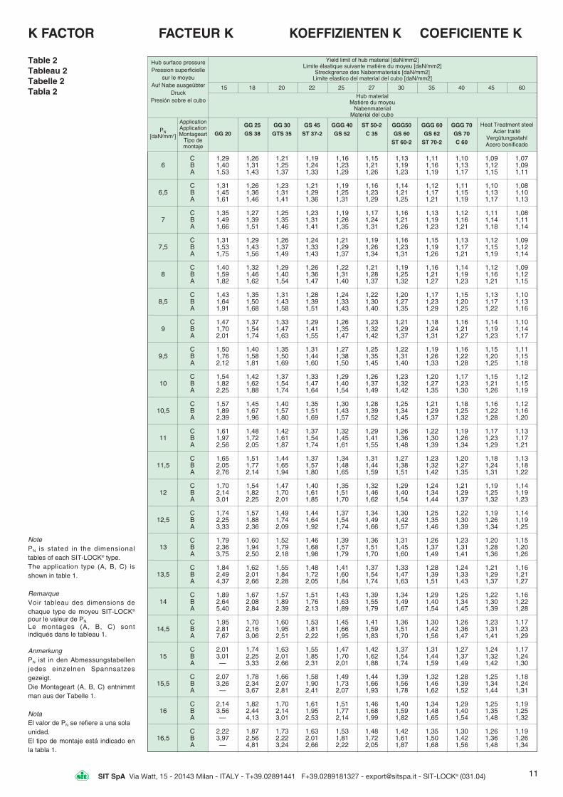
K FACTOR
Table 2 Tableau 2 Tabelle 2 Tabla 2
FACTEUR K KOEFFIZIENTEN K COEFICIENTE K
Hub surface pressure Pression superficielle
sur le moyeu Auf Nabe ausgeübter
Druck Presión sobre el cubo
Hub material Matiére du moyeu
NabenmaterialMaterial del cubo
Yield limit of hub material [daN/mm2] Limite élastique suivante matiére du moyeu [daN/mm2]
Streckgrenze des Nabenmaterials [daN/mm2]Limite elastico del material del cubo [daN/mm2]
PN[daN/mm2]
Application Application Montageart
Tipo demontaje
Heat Treatment steel Acier traité
Vergütungsstahl Acero bonificado
15 18 20 22 25 27 30 35 40 45 60
GG 25 GG 30 GS 45 GGG 40 ST 50-2 GGG50 GGG 60 GGG 70
GG 20 GS 38 GTS 35 ST 37-2 GS 52 C 35 GS 60 GS 62 GS 70
ST 60-2 ST 70-2 C 60
NotePN is stated in the dimensionaltables of each SIT-LOCK® type. The application type (A, B, C) isshown in table 1.
RemarqueVoir tableau des dimensions dechaque type de moyeu SIT-LOCK®
pour le valeur de PN.
Le montages (A, B, C) sont indiqués dans le tableau 1.
AnmerkungPN ist in den Abmessungstabellenjedes einzelnen Spannsatzesgezeigt.Die Montageart (A, B, C) entnimmtman aus der Tabelle 1.
NotaEl valor de PN se refiere a una sola unidad. El tipo de montaje está indicado enla tabla 1.

12 SIT SpA Via Watt, 15 - 20143 Milan - ITALY - T+39.02891441 F+39.0289181327 - [email protected] - SIT-LOCK® (031.04)
CAL 1 F25 / 50Spannsatze Aussen-
durchmesserTyp Bohrungsdurch-
messer
CAL 1 F25 / 50Moyeu Dia.
d’assemblage extérieurType Dia. alésage
CAL 1 F25 / 50Self-loking Outside
unit diameterType Bore diameter
CAL 1 F25 / 50Buje Diámetro
exteriorTipo Diámetro interior
EXAMPLE OFCALCULATIONPROCEDURE
EXEMPLE DESELECTION
BERECHNUNGS-BEISPIELE
EJEMPLO DECÁLCULO
Design data• Power transmission element
to be connected: V-pulley • Shaft diameter: 50 mm • Maximum Torque in operation
(Ma): 150 daNm • V-pulley material: cast iron
GG20 • Yield limit of V-pulley material:
15 daN/mm2
Calculation• SIT-LOCK® type: for this kind
of applcation SIT-LOCK® 1 issuggested
• Size selection: 50 x 80 mm (see table at page 13)
• Performance control: it is neces-sary to check the following formula: Mt Ma. From the table at page 13 youobtain Mt = 177 daNm, so theabove condition is verified
• Tolerance: h9 for the shaft -H9 for the SIT-LOCK® bore
• Roughness: Rt 16 • Screws tightening torque:
Ms = 3,7 daNm (see table at page 13)
• Hub surface pressure: from the table at page 13 youcan find the value PN = 11,5daN/mm2
• Application type: in this case itis preferable to adopt the application “C” (see table at page 10) with the centring guide between shaft and hub
• K Factor: it can be obtained through the table at page 11simply by considering the fol-lowing data: - yield limit of hub material =
= 15 daN/mm2
- hub surface pressure = = 11,5 daN/mm2
- application C: K = 1,65 • Hub outside minimum diameter:
Hub min diameter D.K where - D = SIT-LOCK® outside
diameter [mm] - Hub min diameter 80x1,65
== 132 mm
Application• Montage d’une poulie sur
arbre dia. 50 mm. • Couple maximum à transmettre
(Ma) : 150 daNm• Matière de la poulie à gorges
trapézoidales : Fonte GG20. • Limite élastique de la matière
de la poulie : 15 daN/mm2
Sélection• Type de SIT-LOCK® : pour ce
montage le moyeu d’assemblageSIT-LOCK® 1 est préconisé
• Taille: 50x80 mm (voir tableaupage 13)
• Vérification du couple : Mt Ma(voir tableau page 13: Mt =177 daNm)
• Tolérance : h9 pour l’arbre - H9 pour l’alésage
• Rugosité : Rt 16 • Couple de serrage des vis
MS = 3,7 daNm (voir tableau page 13)
• Pression du moyeu : tableau page 13 - valeur PN = 11,5daN/mm2
• Montage type : dans ce cas montage C (voir tableau page 10) avec centrage dumoyeu de la poulie sur l’arbre
• Facteur K = 1,65; voir tableaupage 11 en considérant : - limite élastique = 15 daN/mm2
- pression supeficielle = 11,5 daN/mm2
- application C • Diamètre extérieur minimum
du moyeu de la poulie: moyeu min. dia D.K, avec- D = diamètre extérieur du SIT-LOCK® [mm]
- dia. mini. du moyeu 80x1,65= = 132 mm
Entwurfsdaten• Antriebselement, das zu span-
nen ist: Keilriemenscheibe • Wellendurchmesser: 50 mm • Höchstes übertragenes
Drehmoment: 150 daNm • Material der Keilriemenscheibe:
Grauguß GG20 • Streckgrenze des
Keilriemenscheiben-Materials:15 daN/mm2
Berechnung • SIT-LOCK® Typ: Für solche
Anwendung wird SIT-LOCK® 1empfohlen
• Modellauswahl: 50 x 80 mm (Tabelle auf Seite 13)
• Prüfung der Leistungen: Manmuß sicher sein, daß Mt Ma.Aus der Tabelle auf Seite 13entnimmt man Mt = 177 daNm,so ist die obengenannte Bedingung erfüllt
• Toleranzwert: Welle h9 - Nabe H9• Oberflächenrauheit: Rt 16
Festzieh - Drehmoment der Schrauben:MS = 3,7 daNm (Tabelle auf Seite 13)
• Auf Nabe ausgeübter Druck: Aus der Tabelle auf Seite 13entnimmt man den Wert PN =11,5 daN/mm2
• Montageart: Für solche Anwendung benützt man dieMontageart C (Tabelle auf Seite 10) mit Zentrierführung
• Koeffizient K: Er wird durch denGebrauch der Tabelle auf Seite11 entnommen. Bei derBenützung der folgenden Daten- Streckgrenze des Naben-
materials = 15 daN/mm2
- Auf Nabe ausgeübter Druck= 11,5 daN/mm2
- Montageart C entnimmt man K = 1,65
• Nabenmindestdurchmesser: Mindestdurchmesser der Nabe D.K, dabei ist:
- D = Außendurchmesser desSIT-LOCK® [mm]
- Mindestdurchmesser der Nabe 80x1,65 = 132 mm
Datos• Elemento a fjiar: Polea trapecial• Diámetro del eje: 50 mm • Par máximo (Ma): 150 daNm.• Material del cubo: fundición
GG20 • Límite elastico del material:
15 daN/mm2
Calculo• Tipo: elegimos el SIT-LOCK® 1• Dimensiones: 50 x 80 mm
(tabla pag. 13) • Prestaciones: debemos asegurar-
nos que Mt Ma • En la tabla de la pag.13
encontramos Mt = 177 daNm El valor es suficiente para la aplicación
• Toleracias: eje h9 - cubo H9 • Rugosidad: Rt 16 • Par de apriete de los tornillos:
MS = 3,7 daNm (tabla pag.13)• Presión sobre el cubo: Tabla
pag.13 PN = 11,5 daN/mm2
• Tipo de montaje: en esta apli-cación adoptamos el tipo C (tabla pag.10) con guia de centraje (tipo 1 no es autocentrante)
• Coeficiente K: viene definido en la tabla pag.11, teniendo en cuenta los datos siguientes:- límite elástico del material del
cubo = 15 daN/mm2
- presión sobre el cubo = 11,5daN/mm2
- montaje tipo C Encontramos: K = 1,65
• Diámetro mínimo del cubo: D min cubo D.K, donde:
- D diámetro exterior del SIT-LOCK® [mm]
- D min cubo 80x1,65 = 132mm
CODE DÉSIGNATION KODIERUNG CODIGOSIT-LOCK® self-locking unitsare indicated by a conventionalalphanumerical code whichdescribes type, bore diameterand outside diameter.Example:
SIT-LOCK® moyeau d’assem-blage sont indiqués par unecodification conventionnellealpha-numérique qui décrire letype, le diamétre de l’alésageet le diamétre exterieur.Exemple:
Die SIT-LOCK® Spannsätzehaben eine alphanumerischekodierung, dieTyp,Bohrungsdurch-messer undAussendurchmesser Angibt. Beispiel:
Los buje de sujección SIT-LOCK® se identifican medianteun código alfanumérico queindica el tipo, el diámetro inte-rior y el diámetro exterior. Ej.:

13SIT SpA Via Watt, 15 - 20143 Milan - ITALY - T+39.02891441 F+39.0289181327 - [email protected] - SIT-LOCK® (031.04)
20 x 47 20 17 27,5 27 2.700 21 9 8 M 6 1,522 x 47 20 17 27,5 30 2.700 19,5 9 8 M 6 1,524 x 50 20 17 27,5 36 3.000 19,5 9,5 8 M 6 1,5
25 x 50 20 17 27,5 38 3.000 19 9,5 8 M 6 1,528 x 55 20 17 27,5 47 3.300 18,5 9,5 10 M 6 1,530 x 55 20 17 27,5 50 3.300 17,5 9 5 10 M 6 1,5
32 x 60 20 17 27,5 63 4.000 19,2 10,5 12 M 6 1,535 x 60 20 17 27,5 70 4.000 18 10,5 12 M 6 1,538 x 65 20 17 27,5 87 4.600 18,8 11 14 M 6 1,5
40 x 65 20 17 27,5 92 4.600 18 11 14 M 6 1,542 x 75 24 20 33,5 150 7.200 22,6 12,5 12 M 8 3,745 x 75 24 20 33,5 161 7.200 21 12,5 12 M 8 3,7
48 x 80 24 20 33,5 170 7.100 19,6 11,5 12 M 8 3,750 x 80 24 20 33 5 177 7.100 19 11,5 12 M 8 3,755 x 85 24 20 33,5 227 8.300 20 13 14 M 8 3,7
60 x 90 24 20 33,5 247 8.300 18 12 14 M 8 3,765 x 95 24 20 33,5 304 9.300 19 13 16 M 8 3,770 x 110 28 24 39,5 460 13.200 21 13 14 M10 7
75 x 115 28 24 39,5 490 13.100 19,5 12,5 14 M10 780 x 120 28 24 39,5 520 13.100 18 12 14 M10 785 x 125 28 24 39,5 630 14.800 19,5 13 16 M10 7
90 x 130 28 24 39,5 660 14.700 18 12,5 16 M10 795 x 135 28 24 39,5 790 16.700 19,5 13,5 18 M10 7
100 x 145 33 26 47 960 19.200 19,5 13,5 14 M12 12,7
110 x 155 33 26 47 1.050 19.100 18 12,5 14 M12 12,7120 x 165 33 26 47 1.310 21.800 18,5 13,5 16 M12 12,7130 x 180 38 34 52 1.760 27.200 16,5 11,5 20 M12 12,7
140 x 190 38 34 52 2.090 29.800 16,5 12,5 22 M12 12,7150 x 200 38 34 52 2.420 32.400 17 12,5 24 M12 12,7160 x 210 38 34 52 2.800 35.000 17 13 26 M12 12,7
170 x 225 44 38 60 3.280 38.600 16 12 22 M14 19,5180 x 235 44 38 60 3.780 42.000 16,5 12,5 24 M14 19,5190 x 250 52 46 68 4.650 49.000 15 11,5 28 M14 19,5
200 x 260 52 46 68 5.250 52.500 15 11,5 30 M14 19,5220 x 285 56 50 74 6.800 62.000 15 11,5 26 M16 30240 x 305 56 50 74 8.550 71.500 16 12,5 30 M16 30
260 x 325 56 50 74 10.400 80.000 16,5 13 34 M16 30280 x 355 66 60 86,5 12.800 91.500 14,5 11,5 32 M18 41300 x 375 66 60 86,5 15.300 102.000 15 12 36 M18 41
320 x 405 78 72 100,5 21.000 131.000 15 12 36 M20 59340 x 425 78 72 100,5 22.400 131.000 14,5 11,5 36 M20 59360 x 455 90 84 116 29.400 163.000 14,5 11,5 36 M22 79
380 x 475 90 84 116 30.800 162.000 13,5 11 36 M22 79400 x 495 90 84 116 32.200 161.000 13 10,5 36 M22 79420 x 515 90 84 116 37.000 178.000 13,5 11 40 M22 79
440 x 545 102 96 130 45.000 205.000 13 10,5 40 M24 100460 x 565 102 96 130 46.500 203.000 12,5 10 40 M24 100480 x 585 102 96 130 50.500 215.000 12,5 10 42 M24 100
500 x 605 102 96 130 55.300 220.000 12,5 10 44 M24 100520 x 630 102 96 130 59.200 230.000 12,5 10 45 M24 100540 x 650 102 96 130 61.800 232.000 12 10 45 M24 100
560 x 670 102 96 130 67.000 243.000 12 10 48 M24 100580 x 690 102 96 130 72.700 252.000 12 10 50 M24 100600 x 710 102 96 130 77.000 256.500 12 10 50 M24 100
620 x 730 102 96 130 81.800 264.700 12 10 52 M24 100640 x 750 102 96 130 86.000 269.800 11,5 10 54 M24 100660 x 770 102 96 130 91.900 279.000 12 10 56 M24 100
680 x 790 102 96 130 95.500 282.000 11,5 10 56 M24 100700 x 810 102 96 130 101.800 294.500 11,5 10 60 M24 100720 x 830 102 96 130 106.000 296.500 11,5 10 60 M24 100
740 x 850 102 96 130 112.800 306.500 11,5 10 62 M24 100760 x 870 102 96 130 120.000 317.000 11,5 10 64 M24 100780 x 890 102 96 130 123.500 320.500 11,5 10 65 M24 100
800 x 910 102 96 130 128.700 326.000 11,5 10 66 M24 100820 x 930 102 96 130 136.000 333.000 11 5 10 68 M24 100840 x 950 102 96 130 143.500 344.500 11 5 10 70 M24 100
860 x 970 102 96 130 151.000 352.500 11 5 10 72 M24 100880 x 990 102 96 130 157.800 361.000 11 5 10 74 M24 100900 x 1010 102 96 130 163.500 366.500 11,5 10 75 M24 100
Dimensions andperformances ofstandard types
SIT-LOCK® 1
Not self-centering Non auto-centré Nichtselbstzentrierend No autocentrante
Dimensions Dimensions
AbmessungenDimensiones
PerformancesPressure
LeistungenPrestaciones
Pression Druck
PresiónClamping screws - Vis
Clamping screws - Vis de serrage Befestigungs -Schrauben
Tornillos de aprieteDIN 912 - 12,9
d x D[mm]
H1
[mm]H
[mm]H2
[mm]Mt
[daNm]Pax
[daN]PW
[daN/mm2]PN
[daN/mm2]N°
sizetypeTyptipo
MS
[daNm]
LEGEND LÉGENDE LEGENDE NOMENCLATURAMs (daNm) Screws tightening torque Couple de serrage des vis Festzieh-Drehmoment der Schrauben Par de apriete de los tornillos
Mt (daNm) Transmissible torque Couple transmissible Übertragbares Drehmoment Par transmisible
Pax (daN) Transmissible axial force Force axiale transmissible Übertragbare Axialkraft Fuerza axial transmisible
Pw (daN/mm2 ) Shaft surface pressure Pression superficielle sur l’arbre Auf Welle ausgeübter Druck Presión sobre el eje
Pn (daN/mm2 ) Hub surface pressure Pression superficielle dans l’alésage Auf Nabe ausgeübter Druck Presión sobre el cubo
Using more than one SIT-LOCK® 1 unit, thetotal transmissible torque (Mt) is as follows:1unit : Mt = Mt table 2 units: Mt = Mt table x 1,93 units: Mt = Mt table x 2,74 units: Mt = Mt table x 3,55For SIT-LOCK® 1 we recommend the fol-lowing fits: h 11 for the shaft - H11 for the hub
Pour l’utilisation de 1 ou plusieurs moyeuxSIT-LOCK® le couple devient:1 moyeu Mt = Mt tableau2 moyeu Mt = Mt tableau x 1,93 moyeu Mt = Mt tableau x 2,74 moyeu Mt = Mt tableau x 3,55Pour le moyeu SIT-LOCK® 1 nous recom-mandons:h 11 pour l’arbre - H 11 pour l’alésage du moyeu
Berechnung von Mt mit mehrerenElementen des Modells 1 in Reihe:1 Element : Mt = Mt laut Tabelle2 Elemente: Mt = Mt laut Tabelle x 1,93 Elemente: Mt = Mt laut Tabelle x 2,74 Elemente: Mt = Mt laut Tabelle x 3,55Für den Sitz von SIT-LOCK® 1 empfohleneToleranz:Welle h 11 - Nabe H 11
Cálculo de Mt con varios elementos tipo 1montados en serie:1 elemento: Mt = Mt valor de la tabla2 elementos: Mt = Mt tabla x 1,93 elementos: Mt = Mt tabla x 2,74 elementos: Mt = Mt tabla x 3,55Tolerancias aconsejadas para el aloja-miento del SIT-LOCK® tipo 1: eje h 11 - cubo H 11
Dimensions etperformances desmodèles standard
Abmessungenund Leistungender Standardtypen
Dimensiones yprestaciones de losmodelos standart

14 SIT SpA Via Watt, 15 - 20143 Milan - ITALY - T+39.02891441 F+39.0289181327 - [email protected] - SIT-LOCK® (031.04)
6 x 9 4,5 3,7 - 380 0,25 84 2,5 2,5 3 4 11,5 7,57 x 10 4,5 3,7 - 390 0,30 86 2,5 2,5 3 4 10,5 78 x 11 4,5 3,7 - 530 0,47 117 2,5 2,5 3 4 12 9
9 x 12 4,5 3,7 765 1.560 0,79 176 2,5 2,5 3 4 14 10,510 x 13 4,5 3,7 700 1.560 0,95 191 2,5 2,5 3 4 13,5 10,512 x 15 4,5 3,7 700 1.560 1,14 191 2,5 2,5 3 4 11,5 9
13 x 16 4,5 3,7 650 1.560 1,31 202 2,5 2,5 3 4 11 914 x 18 6,3 5,3 1.100 2.540 2,23 318 3,5 3,5 4,5 5,5 11,5 915 x 19 6,3 5,3 1.080 2.540 2,43 324 3,5 3,5 4,5 5,5 11 8,5
16 x 20 6,3 5,3 1.000 2.540 2,73 342 3,5 3,5 4,5 5,5 10,5 8,517 x 21 6,3 5,3 960 2.540 2,98 351 3,5 3,5 4,5 5,5 10,5 8,518 x 22 6,3 5,3 915 2.540 3,24 361 3,5 3,5 4,5 5,5 10 8
19 x 24 6,3 5,3 1.250 3.600 4,9 522 3,5 3,5 4,5 5,5 14 1120 x 25 6,3 5,3 1.200 3.600 5,3 533 3,5 3,5 4,5 5,5 13,5 10,522 x 26 6,3 5,3 900 3.600 6,6 600 3,5 3,5 4,5 5,5 13,5 11,5
24 x 28 6,3 5,3 840 3.600 7,3 613 3,5 3,5 4,5 5,5 13 1125 x 30 6,3 5,3 1.000 3.600 7,2 577 3,5 3,5 4,5 5,5 11,5 9,528 x 32 6,3 5,3 750 3.600 8,6 633 3,5 3,5 4,5 5,5 11,5 10
30 x 35 6,3 5,3 860 3.600 9,1 608 3,5 3,5 4,5 5,5 10 8,532 x 36 6,3 5,3 790 4.500 13,1 824 3,5 3,5 4,5 5,5 13 11,535 x 40 7 6 1.000 5.400 17,1 977 3,5 3,5 4,5 5,5 12,5 11
36 x 42 7 6 1.170 5.400 16,9 939 3,5 3,5 4,5 5,5 11,5 1038 x 44 7 6 1.100 5.400 18,1 955 3,5 3,5 4,5 5,5 11 9,540 x 45 8 6,6 1.390 6.600 23,1 1.157 3,5 4,5 5,5 6,5 11,5 10,5
42 x 48 8 6,6 1.550 6.600 23,5 1.122 3,5 4,5 5,5 6,5 11 9,545 x 52 10 8,6 2.830 9.900 35,3 1.571 3,5 4,5 5,5 6,5 10,5 9,548 x 55 10 8,6 2.470 13.200 57,2 2.384 3,5 4,5 5,5 6,5 15,5 13,5
50 x 57 10 8,6 2.360 13.200 60,2 2.408 3,5 4,5 5,5 6,5 15 1355 x 62 10 8,6 2.170 13.200 67 2.435 3,5 4,5 5,5 6,5 14 12,556 x 64 12 10,4 2.950 15.720 79 2.820 3,5 4,5 5,5 7 13 11,5
60 x 68 12 10,4 2.750 15.720 86 2.860 3,5 4,5 5,5 7 12,5 1163 x 71 12 10,4 2.650 15.720 91 2.880 3,5 4,5 5,5 7 12 10,565 x 73 12 10,4 2.550 15.720 95 2.920 3,5 4,5 5,5 7 11,5 10
70 x 79 14 12,2 3.100 20.960 138 3.940 3,5 5 6,5 7,5 12,5 1171 x 80 14 12,2 3.100 20.960 140 3.940 3,5 5 6,5 7,5 12 1175 x 84 14 12,2 3.470 20.960 145 3.860 3,5 5 6 5 7,5 11,5 10
80 x 91 17 15 4.800 29.000 220 5.500 4 6 6,5 8 12,5 10,585 x 96 17 15 4.550 30.500 240 5.640 4 6 6,5 8 12 10,590 x 101 17 15 4.360 32.000 273 6.050 4 6 6,5 8 12 10,5
95 x 106 17 15 4.130 33.000 305 6.420 4 6 6,5 8 12 11100 x 114 21 18,7 6.100 44.500 420 8.400 5 6 7 9 12 10,5110 x 124 21 18,7 6.600 48.500 515 9.360 5 6 7 9 12 10,5
120 x 134 21 18,7 6.030 51.000 605 10.080 5 6 7 9 12 10,5130 x 148 28 25,3 9.630 76.500 960 14.760 5 7 9 11 12 10,5140 x 158 28 25,3 8.900 80.050 1.100 15.850 6 7 9 11 12 10,5
150 x 168 28 25,3 8.500 86.000 1.290 17.200 6 7 8 11 12 10,5160 x 178 28 25,3 7.860 90.000 1.460 18.250 6 7 9 11 12 11170 x 191 33 30 11.740 116.000 1.950 22.900 7 9 10 12 12 10,5
180 x 201 33 30 11.130 120.000 2.130 23.600 7 9 10 12 12 10,5190 x 211 33 30 10.500 126.000 2.420 25.500 7 9 10 12 12 11200 x 224 38 34,8 13.420 155.000 3.100 31.000 7 8 11 13 12 10,5
210 x 234 38 34,8 12.720 161.000 3.500 33.300 7 9 11 13 12 11220 x 244 38 34,8 12.210 169.000 3.800 34.500 7 9 11 13 12 11230 x 257 43 39,5 16.450 200.000 4.700 40.800 7 10 12 14 12 10,5
240 x 267 43 39,5 15.740 225.000 5.100 42.500 7 10 12 14 12 11250 x 280 48 44 19.000 206.000 5.200 41.500 7 10 13 16 10 9260 x 290 48 44 18.200 213.200 5.650 43.500 7 10 13 16 10 9
270 x 300 48 44 17.700 220.700 6.100 45.000 7 10 13 16 10 9280 x 313 53 49 20.600 253.600 7.250 52.000 7 11 14 17 10 9290 x 323 53 49 22.200 263.200 7.750 53.500 7 11 14 17 10 9
300 x 333 53 49 21.400 270.400 8.300 55.500 7 11 14 17 10 9320 x 360 65 59 29.200 349.200 11.400 71.000 10 15 20 25 10 9340 x 380 65 59 27.200 367.200 12.850 75.500 10 15 20 25 10 9
360 x 400 65 59 25.800 358.800 14.400 80.000 10 15 20 25 10 9380 x 420 65 59 26.900 406.900 16.050 84.500 10 15 20 25 10 9400 x 440 65 59 25.600 425.600 17.800 89.000 10 15 20 25 10 9
420 x 460 65 59 24.400 444.400 19.600 93.500 10 15 20 25 10 9440 x 480 65 59 23.400 463.300 21.500 98.000 10 15 20 25 10 9460 x 500 65 59 22.400 482.400 23.500 102.000 10 15 20 25 10 9
480 x 520 65 59 23.900 503.900 25.600 107.000 10 15 20 25 10 9500 x 540 65 59 22.900 522.900 27.800 111.000 10 15 20 25 10 9520 x 570 80 73 33.800 678.800 37.200 143.000 12 18 24 30 10 9
540 x 590 80 73 32.600 702.600 40.000 148.000 12 18 24 30 10 9
SIT-LOCK® 2
Not self-centering Non autocentré Nicht selbstzentrierend No autocentrante
Application 1 Montage 1 Anwendungsart 1 Aplicación 1
Application 2 Montage 2 Anwendungsart 2 Aplicación 2
Dimensions Dimensions
Abmessungen Dimensiones
Po Ptot
[daN] [daN]
Performances Performances
Leistungen Prestaciones
Number of elements arranged in parallel Nombre de bagues en parellèle Abstand bei freiem Festziehen
Distancia W
Pressure Pression
Druck Presión
d x D H H1 [mm] [mm] [mm]
Mt Pax 1 2 3 4 PW PN[daNm] [daN] [mm] [mm] [mm] [mm] [daN/mm2] [daN/mm2]
Note - Also SIT-LOCK® 2 in slotted executionare available on request.
Remarque - Les SIT-LOCK® 2 sont possibleen exécution coupé sur demande.
Anmerkung - SIT-LOCK® 2 ist auch in gesch-chitzen Ausführung erhältlich.
Nota - Es posible suministrar SIT-LOCK® 2 enejecución corta.

15SIT SpA Via Watt, 15 - 20143 Milan - ITALY - T+39.02891441 F+39.0289181327 - [email protected] - SIT-LOCK® (031.04)
Détermination de Mt
Mt = x 0,12 x
Les valeurs de Pv et Ms sontindiquées dans le tableau ci-dessous (suivant DIN 912).
Formula to obtain Mt
Mt = x 0,12 x
The values of Pv and Ms arestated in the following table(according to DIN 912).
(Nbre vis x Pv)-Po0,54
d2000
Formel zur Berechnung von Mt
Mt = x 0,12 x
Das Festzieh-Drehmomentder Schrauben (Ms) und derPv-Wert lassen sich aus derfolgenden Tabelle entnehmen(gemäß DIN 912).
(Schraubenanzahl x Pv) - Po d
0,54 2000
Fórmula para el cálculo de Mt
Mt = x 0,12 x
El par de apriete de los tornillosse encuentran en la siguientetable (según DIN 912).
(N° de tornillos x Pv) - Po d
0,54 2000
M 4 390 545 655 0,29 0,41 0,49M 5 635 895 1.070 0,6 0,85 1M 6 900 1.260 1.510 1 1,4 1,7M 7 1.320 1.850 2.220 1,6 2,3 2,8M 8 1.650 2.320 2.790 2,5 3,5 4,1M 9 2.200 3.090 3.710 3,6 5,1 6,1M10 2.620 3.690 4.430 4,9 6,9 8,3M12 3.830 5.400 6.450 8,6 12 14,5M14 5.250 7.400 8.850 13,5 19 23M16 7.300 10.200 12.300 21 29,5 35,5M18 8.800 12.400 14.800 29 40,5 48,5M20 11.400 16.000 19.200 41 58 69M22 14.100 19.900 23.900 55 78 93M24 16.400 23.000 27.600 71 100 120M27 21.500 30.200 36.300 105 150 180M30 26.200 36.800 44.200 145 200 240
DIN 912Screw diameter
Diamètre visSchraubendurchmesser Diámetro de los tornillos
Pv [daN] Ms [daNm]
8,8 10,9 12,9 8,8 10,9 12,9
WARNING: the values stated in thiscatalogue are valid for application 1.With application 2, Mt, Pax, Pw and PN
are increased by 25%.
Using more than one SIT-LOCK® 2unit, the total transmissible torque(Mt) is as follows:1 unit : Mt = Mt table 2 units: Mt = Mt table x 1,55 3 units: Mt = Mt table x 1,85 4 units: Mt = Mt table x 2,02
Design of the flange thickness (Sf)a) For applications with screws quality
12.9 (DIN 912): Sf = screw diameter x 1,8 [mm]
b) For applications with screws quality 8.8 (DIN 912): Sf = screw diameter x 1,3 [mm]
Design of the screws center distance (I)a) For applications with screws clamped
on the hub: I = D + 12 + screw diameter [mm]
b) For applications with screws clampedon the shaft: I = d - 12 - screw diameter [mm].
ATTENTION: les valeurs indiquées dansle tableau sont uniquement valablespour le montage 1. Pour le montage 2,elles doivent être augmentées de 25%.
Si plusieurs SIT-LOCK® 2 sont utili-sés dans un même montage, le cou-ple total transmissible doit être cal-culé comme ci-dessous:1 moyeu : Mt = Mt tableau 2 moyeux : Mt = Mt tableau x 1,55 3 moyeux : Mt = Mt tableau x 1,85 4 moyeux : Mt = Mt tableau x 2,02
Calcul de l’épaisseur du flasque (Sf):a) Pour montage avec vis qualité 12,9
suivant DIN 912 : Sf = ø vis x 1,8 [mm]
b) pour montage avec vis qualité 8,8 suivant DIN 912: Sf = ø vis x 1,3 [mm]
Calcul de l’entraxe des vis (I):a) Pour montage avec trous taraudés
dans le moyeu: I = D + 12 + ø de la vis [mm]
b) Pour montage avec trous taraudés dans l’arbre: I = D - 12 - ø de la vis [mm]
ACHTUNG: Die in der Tabelle genanntenWerte gelten für die Anwendungsart 1. Bei Anwendungsart 2 erhöhen sich dieWerte Mt, Pax, Pw und PN, um ca. 25%.
Berechnung von Mt mit mehrerenElementen des Modells 2 in Reihe:1 Element : Mt = Mt laut Tabelle 2 Elemente: Mt = Mt laut Tabelle x 1,553 Elemente: Mt = Mt laut Tabelle x 1,854 Elemente: Mt = Mt laut Tabelle x 2,02
Berechnung der Flanschdicke (Sf)a) Für Anwendungen mit Schrauben
der Klasse 12,9 (DIN 912) Sf = Schraubendurchm. x 1,8 [mm]
b) Für Anwendungen mit Schrauben der Klasse 8,8 (DIN 912) Sf = Schraubendurchm. x 1,3 [mm]
Berechnung des Achsabstands derBefestigungsschrauben (I)a) Für Anwendungen mit Befestigung
an der Nabe I = D + 12 + Schraubendurchmesser [mm]
b) Für Anwendungen mit Befestigung an der Welle I = d - 12 - Schraubendurchmesser [mm]
ATENCION: Los valores de las tablasson solo aplicación para montaje tipo 1.Para aplicación 2, Mt, Pax, Pw, PN
aumentan alrededor de un 25%.
Cálculo de Mt con más de 1 elemen-to tipo 2 en serie1 elemento : Mt = Mt valor de tabla 2 elementos: Mt = Mt tabla x 1,55 3 elementos: Mt = Mt tabla x 1,85 4 elementos: Mt = Mt tabla x 2,02
Cálculo de espesor del aro de apriete (Sf)a) Para aplicaciones con tornillos de
tipo 12.9 (DIN 912) Sf = ø tornillo x 1,8 [mm]
b) Para aplicaciones con tornillos de tipo 8.8 (DIN 912) Sf = ø tornillo x 1,3 [mm]
Cálculo de la distancia entre ejes delos tornillos (I)a) Para apriete en el cubo I = D + 12 +
ø tornillo [mm] b) Para apriete en el eje I = d - 12 - ø
tornillo [mm].
Note - Flanges are available on request. Remarque - Les flasques peuvent êtrelivrés sur demande.
Anmerkung - Auf Anfrage können dieFlansche geliefert werden.
LEGEND LÉGENDE LEGENDE NOMENCLATURAMs (daNm) Screws tightening torque Couple de serrage des vis Festzieh-Drehmoment der Schrauben Par de apriete de los tornillosMt (daNm) Transmissible torque Couple transmissible Übertragbares Drehmoment Par transmisiblePax (daN) Transmissible axial force Force axiale transmissible Übertragbare Axialkraft Fuerza axial transmisiblePw (daN/mm2) Shaft surface pressure Pression superficielle sur l’arbre Auf Welle ausgeübter Druck Presión sobre el ejePN (daN/mm2) Hub surface pressure Pression superficielle dans l’alésage Auf Nabe ausgeübter Druck Presión sobre el cuboPo (daN) Axial force necessary to Force axiale nécessaire pour vaincre le Erforderliche Axialkraft zur Beseitigung Fuerza necesaria para vencer los juegos
overcome the clearances frottement créé par l’état de surface durch Bearbeitungstoleranzen debidos a fabricacion determined by the verursachten Spielsmachining allowances
Ptot (daN) Total axial force Force axiale totale Gesamte Axialkraft Fuerza axial total
Nota - Los aros de apriete son suministrables sobre pedido.
For SIT-LOCK® 2 we recommend the fol-lowing fits:- d 40 mm: h 6 for the shaft - H 7 for the hub
- d > 40 mm: h 8 for the shaft - H 8 for the hub
Pour SIT-LOCK® 2 nous recommandons:- d inférieur ou égal à 40 mm : h 6 pour l’arbre
H 7 pour l’alésage - d supérior à 40 mm: h 8 pour l’arbre H 8
pour l’alésage
Für den Sitz von SIT-LOCK® 2 empfohleneToleranz:- d 40 mm: Welle h 6 - Nabe H 7 - d > 40 mm: Welle h 8 - Nabe H 8
Tolerancias aconsejadas
- d 40 mm: eje h 6 - cubo H 7 - d > 40 mm: eje H 8 - cubo H 8
(N° screws x PV)- PO
0,54d
2000
16 SIT SpA Via Watt, 15 - 20143 Milan - ITALY - T+39.02891441 F+39.0289181327 - [email protected] - SIT-LOCK® (031.04)
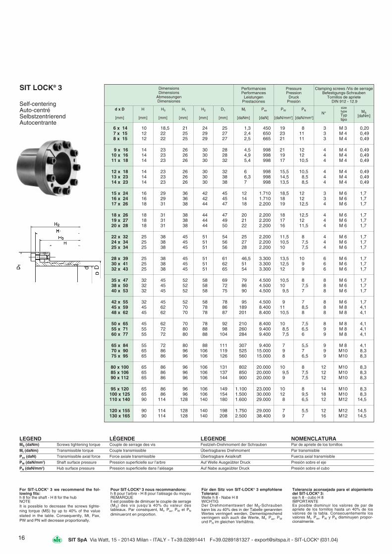
SIT LOCK® 3
Self-centering Auto-centré Selbstzentrierend Autocentrante
6 x 14 10 18,5 21 24 25 1,3 450 19 8 3 M 3 0,207 x 15 12 22 25 29 27 2,4 650 23 11 3 M 4 0,498 x 15 12 22 25 29 27 2,5 665 21 11 3 M 4 0,49
9 x 16 14 23 26 30 28 4,5 998 21 12 4 M 4 0,4910 x 16 14 23 26 30 28 4,9 998 19 12 4 M 4 0,4911 x 18 14 23 26 30 32 5,4 998 17 10,5 4 M 4 0,49
12 x 18 14 23 26 30 32 6 998 15,5 10,5 4 M 4 0,4913 x 23 14 23 26 30 38 6,3 998 14,5 8,5 4 M 4 0,4914 x 23 14 23 26 30 38 7 998 13,5 8,5 4 M 4 0,49
15 x 24 16 29 36 42 45 12 1.710 18,5 12 3 M 6 1,716 x 24 16 29 36 42 45 14 1.710 18 12 3 M 6 1,717 x 26 18 31 38 44 47 18 2.200 19 12,5 4 M 6 1,7
18 x 26 18 31 38 44 47 20 2.200 18 12,5 4 M 6 1,719 x 27 18 31 38 44 49 21 2.200 17 12 4 M 6 1,720 x 28 18 31 38 44 50 22 2.200 16 11,5 4 M 6 1,7
22 x 32 25 38 45 51 54 25 2.200 11,5 8 4 M 6 1,724 x 34 25 38 45 51 56 27 2.200 10,5 7,5 4 M 6 1,725 x 34 25 38 45 51 56 28 2.200 10 7,5 4 M 6 1,7
28 x 39 25 38 45 51 61 46,5 3.300 13,5 10 6 M 6 1,730 x 41 25 38 45 51 62 51 3.300 12,5 9 6 M 6 1,732 x 43 25 38 45 51 65 54 3.300 12 9 6 M 6 1,7
35 x 47 32 45 52 58 69 79 4.500 10,5 8 8 M 6 1,738 x 50 32 45 52 58 72 86 4.500 10 7,5 8 M 6 1,740 x 53 32 45 52 58 75 90 4.500 9,5 7 8 M 6 1,7
42 x 55 32 45 52 58 78 95 4.500 9 7 8 M 6 1,745 x 59 45 62 70 78 86 189 8.400 11 8,5 8 M 8 4,148 x 62 45 62 70 78 87 201 8.400 10,5 8 8 M 8 4,1
50 x 65 45 62 70 78 92 210 8.400 10 7,5 8 M 8 4,155 x 71 55 72 80 88 98 260 9.400 8,5 6,5 9 M 8 4,160 x 77 55 72 80 88 104 284 9.400 7,5 6 9 M 8 4,1
65 x 84 55 72 80 88 111 307 9.400 7 5,5 9 M 8 4,170 x 90 65 86 96 106 119 525 15.000 9 7 9 M10 8,375 x 95 65 86 96 106 126 560 15.000 8 6,5 9 M10 8,3
80 x 100 65 86 96 106 131 802 20.000 10 8 12 M10 8,385 x 106 65 86 96 106 137 850 20.000 9,5 7,5 12 M10 8,390 x 112 65 86 96 106 144 900 20.000 9 7,5 12 M10 8,3
95 x 120 65 86 96 106 149 1.100 23.000 10 8 14 M10 8,3100 x 125 65 86 96 106 154 1.500 30.000 12 9,5 18 M10 8,3110 x 140 90 114 128 140 180 1.600 29.000 8 6,5 12 M12 14,5
120 x 155 90 114 128 140 198 1.750 29.000 7 5,5 12 M12 14,5130 x 165 90 114 128 140 208 2.500 38.400 9 7 16 M12 14,5
LEGEND LÉGENDE LEGENDE NOMENCLATURAMS (daNm) Screws tightening torque Couple de serrage des vis Festzieh-Drehmoment der Schrauben Par de apriete de los tornillos
Mt (daNm) Transmissible torque Couple transmissible Übertragbares Drehmoment Par transmisible
Pax (daN) Transmissible axial force Force axiale transmissible Übertragbare Axialkraft Fuerza axial transmisible
PW (daN/mm2) Shaft surface pressure Pression superficielle sur l’arbre Auf Welle Ausgeübter Druck Presión sobre el eje
PN (daN/mm2) Hub surface pressure Pression superficielle dans l’alésage Auf Nabe ausgeübter Druck Presión sobre el cubo
Dimensions Dimensions
Abmessungen Dimensiones
PerformancesPerformances
LeistungenPrestaciones
Pressure Pression
DruckPresión
Clamping screws /Vis de serrageBefestigungs-Schrauben
Tornillos de aprieteDIN 912 - 12.9
d x D H H0 H1 H2 D1 Mt Pax PW PN
[mm] [mm] [mm] [mm] [mm] [mm] [daNm] [daN] [daN/mm2] [daN/mm2]
sizetypeTyptipo
MS[daNm]
N°
For SIT-LOCK® 3 we recommend the fol-lowing fits:h 8 for the shaft - H 8 for the hubNOTEIt is possible to decrease the screws tighte-ning torque (MS) by up to 40% of the valuestated in the table. Consequently, Mt, Pax,PW and PN will decrease proportionally.
Pour SIT-LOCK® 3 nous recommandons:h 8 pour l’arbre - H 8 pour l’alésage du moyeuREMARQUEIl est possible de diminuer le couple de serrage(MS) des vis jusqu’à 40% du valeur destableaux. Par conséquent, Mt, Pax, PW et PN
diminueront en proportion.
Für den Sitz von SIT-LOCK® 3 empfohleneToleranz:Welle h 8 - Nabe H 8WICHTIGDer Drehmomentswert der MS-Schraubenkann bis zu 40% des in der Tabelle genanntenWertes verringert werden. Dementsprechendverringern sich auch die Werte, Mt, Pax, PWund PN im gleichen Verhältnis.
Tolerancia aconsejada para el alojamientodel SIT-LOCK® 3:eje h 8 - cubo H 8IMPORTANTEEs posible disminuir los valores de par deapriete de los tornillos hasta un 40% de losvalores de la tabla. Consecuentemente losvalores Mt, Pax, PW y PN disminuyen propor-cionalmente.
Dd

H2
H1
H
d D
17SIT SpA Via Watt, 15 - 20143 Milan - ITALY - T+39.02891441 F+39.0289181327 - [email protected] - SIT-LOCK® (031.04)
DimensionsDimensions
AbmessungenDimensiones
Clamping screwsVis de serrage
Befestigungs-SchraubenTornillos de apriete
DIN 912 - 12.9
SIT-LOCK® 4
Self-centering Auto-centré Selbstzentrierend Autocentrante
LEGEND LÉGENDE LEGENDE NOMENCLATURAMS (daNm) Screws tightening torque Couple de serrage des vis Festzieh-Drehmoment der Schrauben Par de apriete de los tornillos
Mt (daNm) Transmissible torque Couple transmissible Übertragbares Drehmoment Par transmisible
Pax (daN) Transmissible axial force Force axiale transmissible Übertragbare Axialkraft Fuerza axial transmisible
PW (daN/mm2) Shaft surface pressure Pression superficielle sur l’arbre Auf Welle ausgeübter Druck Presión sobre el eje
PN (daN/mm2) Hub surface pressure Pression superficielle dans l’alésage Auf Nabe ausgeübter Druck Presión sobre el cubo
For SIT-LOCK® 4 we recommend the fol-lowing fits:Shaft h8 - Hub H8
Pour SIT-LOCK® 4 nous recommandons:Arbre h8 - Moyeu H8
Für den Sitz von SIT-LOCK® 4 empfohleneToleranz:Welle h 8 - Nabe H 8
Tolerancia aconsejada para el alojamientodel SIT-LOCK® 4: Eje h 8 - Cubo H 8
25 x 50 39 45 51 95 7.600 24,5 12,2 8 M 6 1,728 x 55 39 45 51 107 7.600 21,9 11,1 8 M 6 1,730 x 55 39 45 51 115 7.600 20,4 11,1 8 M 6 1,735 x 60 39 45 51 134 7.600 17,5 10,2 8 M 6 1,7
38 x 65 39 45 51 145 7.600 16,1 9,4 8 M 6 1,740 x 65 39 45 51 153 7.600 15,3 9,4 8 M 6 1,742 x 75 56 64 72 297 14.100 18,8 10,5 8 M 8 4,1
45 x 75 56 64 72 315 14.100 17,5 10,5 9 M 8 4,148 x 80 56 64 72 400 16.600 16,4 9,8 9 M 8 4,150 x 80 56 64 72 415 16.600 15,2 9,8 9 M 8 4,1
55 x 85 56 64 72 455 16.600 14,3 9,3 9 M 8 4,160 x 90 56 64 72 620 20.700 16,4 10,9 11 M 8 4,165 x 95 56 64 72 675 20.700 15,2 10,4 11 M 8 4,1
70 x 110 70 78 88 1.155 33.000 17,9 11,4 11 M10 8,375 x 115 70 78 88 1.235 33.000 16,7 10,9 11 M10 8,380 x 120 70 78 88 1.580 39.600 18,8 12,5 12 M10 8,3
85 x 125 70 78 88 1.680 39.600 17,7 12,0 12 M10 8,390 x 130 70 78 88 1.780 39.600 16,7 11,5 13 M10 8,395 x 135 70 78 88 1.800 39.600 15,8 11,1 13 M10 8,3
100 x 145 90 100 112 2.880 57.600 17,0 11,7 12 M12 14,5110 x 155 90 100 112 3.170 57.600 15,5 11,0 13 M12 14,5120 x 165 90 100 112 4.030 67.300 16,5 12,0 15 M12 14,5
130 x 180 104 116 130 5.140 79.100 15,5 11,2 13 M14 23140 x 190 104 116 130 6.460 92.300 16,8 12,4 15 M14 23150 x 200 104 116 130 7.910 105.500 17,9 13,5 16 M14 23
160 x 210 104 116 130 8.440 105.500 16,8 12,8 17 M14 23170 x 225 134 146 162 10.900 128.300 14,9 11,3 15 M16 35,5180 x 235 134 146 162 13.200 146.600 16,1 12,4 16 M16 35,5
190 x 250 134 146 162 13.900 146.600 15,3 11,6 17 M16 35,5200 x 260 134 146 162 14.650 146.600 14,5 11,2 17 M16 35,5220 x 285 134 146 162 20.150 183.300 16,5 12,7 20 M16 35,5
240 x 305 134 146 162 24.200 201.700 16,6 13,1 22 M16 35,5260 x 325 134 146 162 26.200 201.700 15,4 12,3 22 M16 35,5280 x 355 165 177 197 40.000 286.200 16,4 13,0 20 M20 69,0
300 x 375 165 177 197 47.200 314.800 16,9 13,5 22 M20 69,0320 x 405 165 177 197 50.350 314.800 15,8 12,5 22 M20 69,0340 x 425 165 177 197 58.350 343.400 16,2 13,0 24 M20 69,0
360 x 455 190 202 224 70.500 391.800 15,2 12,0 22 M22 93,0380 x 475 190 202 224 88.000 463.100 17,0 13,6 26 M22 93,0400 x 495 190 202 224 92.600 463.100 16,2 13,1 26 M22 93,0
d x D[mm]
H[mm]
H1[mm]
H2[mm] N°
MS[da Nm]
sizetypeTyptipo
Mt[da Nm]
Pax[da N]
PW [da N/mm2]
PN[da N/mm2]
PerformancesPerformances
LeistungenPrestaciones
PressurePression
DruckPresión
SIT LOCK 4
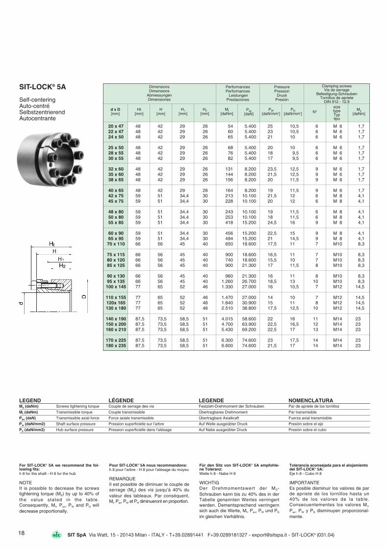
18 SIT SpA Via Watt, 15 - 20143 Milan - ITALY - T+39.02891441 F+39.0289181327 - [email protected] - SIT-LOCK® (031.04)
20 x 47 48 42 29 26 54 5.400 25 10,5 6 M 6 1,722 x 47 48 42 29 26 60 5.400 23 10,5 6 M 6 1,724 x 50 48 42 29 26 65 5.400 21 10 6 M 6 1,7
25 x 50 48 42 29 26 68 5.400 20 10 6 M 6 1,7 28 x 55 48 42 29 26 76 5.400 18 9,5 6 M 6 1,730 x 55 48 42 29 26 82 5.400 17 9,5 6 M 6 1,7
32 x 60 48 42 29 26 131 8.200 23,5 12,5 9 M 6 1,735 x 60 48 42 29 26 144 8.200 21,5 12,5 9 M 6 1,738 x 65 48 42 29 26 156 8.200 20 11,5 9 M 6 1,7
40 x 65 48 42 29 26 164 8.200 19 11,5 9 M 6 1,742 x 75 59 51 34,4 30 213 10.100 21,5 12 6 M 8 4,145 x 75 59 51 34,4 30 228 10.100 20 12 6 M 8 4,1
48 x 80 59 51 34,4 30 243 10.100 19 11,5 6 M 8 4,150 x 80 59 51 34,4 30 253 10.100 18 11,5 6 M 8 4,155 x 85 59 51 34,4 30 418 15.200 24,5 16 9 M 8 4,1
60 x 90 59 51 34,4 30 456 15.200 22,5 15 9 M 8 4,165 x 95 59 51 34,4 30 494 15.200 21 14,5 9 M 8 4,170 x 110 66 56 45 40 650 18.600 17,5 11 7 M10 8,3
75 x 115 66 56 45 40 900 18.600 16,5 11 7 M10 8,380 x 120 66 56 45 40 740 18.600 15,5 10 7 M10 8,385 x 125 66 56 45 40 900 21.300 17 11,5 8 M10 8,3
90 x 130 66 56 45 40 960 21.300 16 11 8 M10 8,395 x 135 66 56 45 40 1.260 26.700 18,5 13 10 M10 8,3100 x 145 77 65 52 46 1.330 27.000 16 10,5 7 M12 14,5
110 x 155 77 65 52 46 1.470 27.000 14 10 7 M12 14,5120x 165 77 65 52 46 1.840 30.900 15 11 8 M12 14,5130 x 180 77 65 52 46 2.510 38.800 17,5 12,5 10 M12 14,5
140 x 190 87,5 73,5 58,5 51 4.015 58.600 22 16 11 M14 23150 x 200 87,5 73,5 58,5 51 4.700 63.900 22,5 16,5 12 M14 23160 x 210 87,5 73,5 58,5 51 5.430 69.200 22,5 17 13 M14 23
170 x 225 87,5 73,5 58,5 51 6.300 74.600 23 17,5 14 M14 23180 x 235 87,5 73,5 58,5 51 6.600 74.600 21,5 17 14 M14 23
DimensionsDimensions
AbmessungenDimensiones
Performances Performances
Leistungen Prestaciones
Pressure Pression
DruckPresión
Clamping screws Vis de serrage
Befestigung-SchraubenTornillos de apriete
DIN 912 - 12.9
d x D[mm]
Ht[mm]
H[mm]
H1[mm]
H2[mm]
Mt [daNm]
Pax[daN]
PW[daN/mm2]
PN[daN/mm2] N°
sizetype Typtipo
Ms[daNm]
SIT-LOCK® 5A
Self-centering Auto-centré SelbstzentrierendAutocentrante
LEGEND LÉGENDE LEGENDE NOMENCLATURAMs (daNm) Screws tightening torque Couple de serrage des vis Festzieh-Drehmoment der Schrauben Par de apriete de los tornillos
Mt (daNm) Transmissible torque Couple transmissible Übertragbares Drehmoment Par transmisible
Pax (daN) Transmissible axial force Force axiale transmissible Übertragbare Axialkraft Fuerza axial transmisible
Pw (daN/mm2) Shaft surface pressure Pression superficielle sur l’arbre Auf Welle ausgeübter Druck Presión sobre el eje
Pn (daN/mm2) Hub surface pressure Pression superficielle dans l’alésage Auf Nabe ausgeübter Druck Presión sobre el cubo
For SIT-LOCK® 5A we recommend the fol-lowing fits:h 8 for the shaft - H 8 for the hub
NOTEIt is possible to decrease the screwstightening torque (MS) by up to 40% ofthe value stated in the table.Consequently, Mt, Pax, PW and PN willdecrease proportionally.
Pour SIT-LOCK® 5A nous recommandons:h 8 pour l’arbre - H 8 pour l’alésage du moyeu
REMARQUEIl est possible de diminuer le couple deserrage (MS) des vis jusqu’à 40% duvaleur des tableaux. Par conséquent,Mt, Pax, PW et PN diminueront en proportion.
Für den Sitz von SIT-LOCK® 5A empfohle-ne Toleranz:Welle h 8 - Nabe H 8
WICHTIGDer Drehmomentswert der MS-Schrauben kann bis zu 40% des in derTabelle genannten Wertes verringertwerden. Dementsprechend verringernsich auch die Werte, Mt, Pax, PW und PN
im gleichen Verhältnis.
Tolerancia aconsejada para el alojamientodel SIT-LOCK® 5A:Eje h 8 - Cubo H 8
IMPORTANTEEs posible disminuir los valores de parde apriete de los tornillos hasta un40% de los valores de la table.Consecuentementes los valores Mt,Pax, PW y PN disminuyen proporcional-mente.
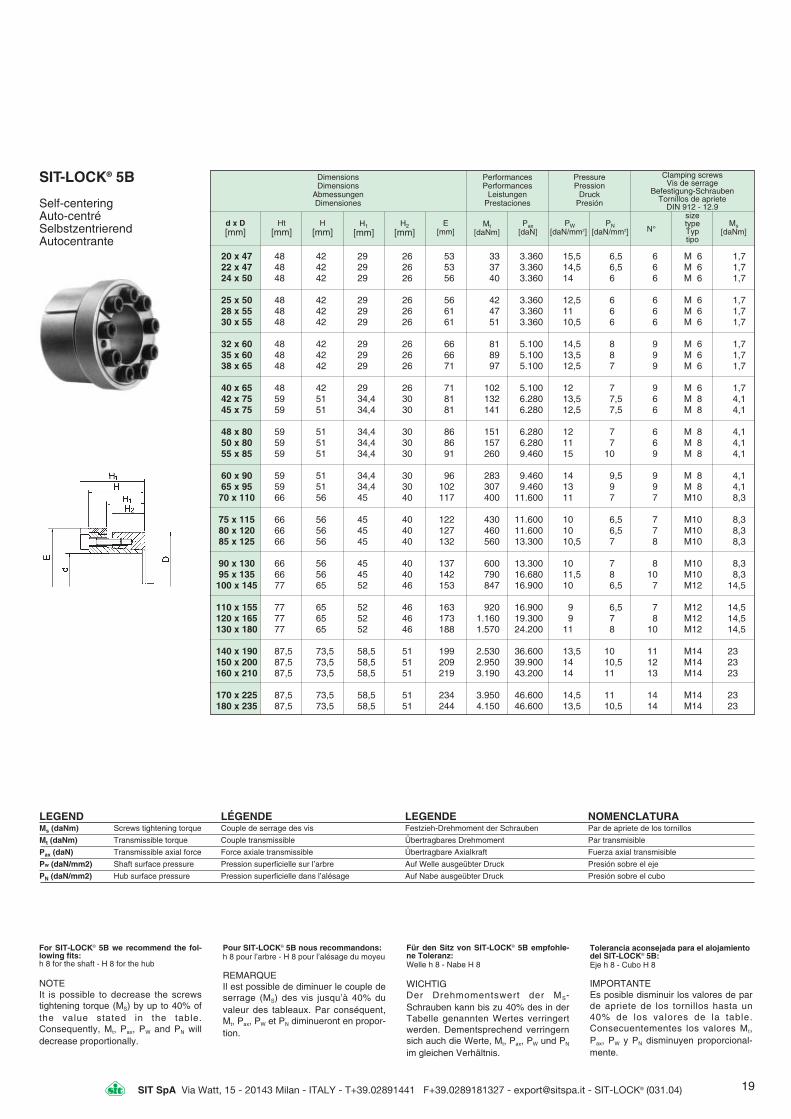
19SIT SpA Via Watt, 15 - 20143 Milan - ITALY - T+39.02891441 F+39.0289181327 - [email protected] - SIT-LOCK® (031.04)
20 x 47 48 42 29 26 53 33 3.360 15,5 6,5 6 M 6 1,722 x 47 48 42 29 26 53 37 3.360 14,5 6,5 6 M 6 1,724 x 50 48 42 29 26 56 40 3.360 14 6 6 M 6 1,7
25 x 50 48 42 29 26 56 42 3.360 12,5 6 6 M 6 1,728 x 55 48 42 29 26 61 47 3.360 11 6 6 M 6 1,730 x 55 48 42 29 26 61 51 3.360 10,5 6 6 M 6 1,7
32 x 60 48 42 29 26 66 81 5.100 14,5 8 9 M 6 1,735 x 60 48 42 29 26 66 89 5.100 13,5 8 9 M 6 1,738 x 65 48 42 29 26 71 97 5.100 12,5 7 9 M 6 1,7
40 x 65 48 42 29 26 71 102 5.100 12 7 9 M 6 1,742 x 75 59 51 34,4 30 81 132 6.280 13,5 7,5 6 M 8 4,145 x 75 59 51 34,4 30 81 141 6.280 12,5 7,5 6 M 8 4,1
48 x 80 59 51 34,4 30 86 151 6.280 12 7 6 M 8 4,150 x 80 59 51 34,4 30 86 157 6.280 11 7 6 M 8 4,155 x 85 59 51 34,4 30 91 260 9.460 15 10 9 M 8 4,1
60 x 90 59 51 34,4 30 96 283 9.460 14 9,5 9 M 8 4,165 x 95 59 51 34,4 30 102 307 9.460 13 9 9 M 8 4,170 x 110 66 56 45 40 117 400 11.600 11 7 7 M10 8,3
75 x 115 66 56 45 40 122 430 11.600 10 6,5 7 M10 8,380 x 120 66 56 45 40 127 460 11.600 10 6,5 7 M10 8,385 x 125 66 56 45 40 132 560 13.300 10,5 7 8 M10 8,3
90 x 130 66 56 45 40 137 600 13.300 10 7 8 M10 8,395 x 135 66 56 45 40 142 790 16.680 11,5 8 10 M10 8,3100 x 145 77 65 52 46 153 847 16.900 10 6,5 7 M12 14,5
110 x 155 77 65 52 46 163 920 16.900 9 6,5 7 M12 14,5120 x 165 77 65 52 46 173 1.160 19.300 9 7 8 M12 14,5130 x 180 77 65 52 46 188 1.570 24.200 11 8 10 M12 14,5
140 x 190 87,5 73,5 58,5 51 199 2.530 36.600 13,5 10 11 M14 23150 x 200 87,5 73,5 58,5 51 209 2.950 39.900 14 10,5 12 M14 23160 x 210 87,5 73,5 58,5 51 219 3.190 43.200 14 11 13 M14 23
170 x 225 87,5 73,5 58,5 51 234 3.950 46.600 14,5 11 14 M14 23180 x 235 87,5 73,5 58,5 51 244 4.150 46.600 13,5 10,5 14 M14 23
DimensionsDimensions
Abmessungen Dimensiones
Performances Performances
Leistungen Prestaciones
Pressure Pression
DruckPresión
Clamping screws Vis de serrage
Befestigung-Schrauben Tornillos de apriete
DIN 912 - 12.9
d x D [mm]
Ht[mm]
H[mm]
H1
[mm]H2
[mm]Mt
[daNm]Pax
[daN]PW
[daN/mm2]PN
[daN/mm2] N°
sizetype Typtipo
Ms[daNm]
E[mm]
SIT-LOCK® 5B
Self-centeringAuto-centréSelbstzentrierendAutocentrante
LEGEND LÉGENDE LEGENDE NOMENCLATURAMs (daNm) Screws tightening torque Couple de serrage des vis Festzieh-Drehmoment der Schrauben Par de apriete de los tornillos
Mt (daNm) Transmissible torque Couple transmissible Übertragbares Drehmoment Par transmisible
Pax (daN) Transmissible axial force Force axiale transmissible Übertragbare Axialkraft Fuerza axial transmisible
Pw (daN/mm2) Shaft surface pressure Pression superficielle sur l’arbre Auf Welle ausgeübter Druck Presión sobre el eje
PN (daN/mm2) Hub surface pressure Pression superficielle dans l’alésage Auf Nabe ausgeübter Druck Presión sobre el cubo
For SIT-LOCK® 5B we recommend the fol-lowing fits:h 8 for the shaft - H 8 for the hub
NOTEIt is possible to decrease the screwstightening torque (MS) by up to 40% ofthe value stated in the table.Consequently, Mt, Pax, PW and PN willdecrease proportionally.
Pour SIT-LOCK® 5B nous recommandons:h 8 pour l’arbre - H 8 pour l’alésage du moyeu
REMARQUEIl est possible de diminuer le couple deserrage (MS) des vis jusqu’à 40% duvaleur des tableaux. Par conséquent,Mt, Pax, PW et PN diminueront en propor-tion.
Für den Sitz von SIT-LOCK® 5B empfohle-ne Toleranz:Welle h 8 - Nabe H 8
WICHTIGDer Drehmomentswert der MS-Schrauben kann bis zu 40% des in derTabelle genannten Wertes verringertwerden. Dementsprechend verringernsich auch die Werte, Mt, Pax, PW und PN
im gleichen Verhältnis.
Tolerancia aconsejada para el alojamientodel SIT-LOCK® 5B:Eje h 8 - Cubo H 8
IMPORTANTEEs posible disminuir los valores de parde apriete de los tornillos hasta un40% de los valores de la table.Consecuentementes los valores Mt,Pax, PW y PN disminuyen proporcional-mente.

20 SIT SpA Via Watt, 15 - 20143 Milan - ITALY - T+39.02891441 F+39.0289181327 - [email protected] - SIT-LOCK® (031.04)
20 x 47 17 22 28 34 38 3.800 29,5 12 5 5 M6 1,422 x 47 17 22 28 34 41 3.800 27 12,5 5 M6 1,424 x 50 17 22 28 34 45 3.800 24,5 12 5 M6 1,4
25 x 50 17 22 28 34 57 4.560 28,5 14 6 M6 1,428 x 55 17 22 28 34 63 4.560 25,5 13 6 M6 1,430 x 55 17 22 28 34 66 4.560 23,5 13 6 M6 1,4
32 x 60 17 22 28 34 97 6.050 29,5 15,5 8 M6 1,435 x 60 17 22 28 34 106 6.050 27 15,5 8 M6 1 438 x 65 17 22 28 34 115 6.050 25 14,5 8 M6 1 4
40 x 65 17 22 28 34 121 6.050 23,5 14,5 8 M6 1,442 x 75 20 25 33 41 205 9.800 30 17 7 M8 3,545 x 75 20 25 33 41 220 9.800 29 17 7 M8 3 5
48 x 80 20 25 33 41 235 9.800 27 16 7 M8 3,550 x 80 20 25 33 41 245 9.800 26 16 7 M8 3,555 x 85 20 25 33 41 308 11.200 27 17,5 8 M8 3,5
60 x 90 20 25 33 41 336 11.200 24,5 16,5 8 M8 3,565 x 95 20 25 33 41 409 12.600 25,5 17,5 9 M8 3,570 x 110 24 30 40 50 630 17.900 28 18 8 M10 7
75 x 115 24 30 40 50 670 17.900 26 17 8 M10 780 x 120 24 30 40 50 715 17.900 25 17 8 M10 785 x 125 24 30 40 50 850 20.000 26 18 9 M10 7
90 x 130 24 30 40 50 910 20.000 25 17 9 M10 795 x 135 24 30 40 50 1.060 22.400 26 18 10 M10 7
100 x 145 26 32 44 56 1.340 26.800 27 19 8 M12 12,5
110 x 155 26 32 44 56 1.460 26.800 24 18 8 M12 12,5120 x 165 26 32 44 56 1.790 29.800 25 18 9 M12 12,5130 x 180 34 40 54 64 2.600 40.000 24 17 12 M12 12,5
140 x 190 34 40 54 68 2.700 38.400 21 15 9 M14 19150 x 200 34 40 54 68 3.300 44.000 23 17 10 M14 19160 x 210 34 40 54 68 3.800 47.900 23 17 11 M14 19
170 x 225 44 50 64 78 4.500 53.000 18 13 12 M14 19180 x 235 44 50 64 78 4.700 53.000 17 13 12 M14 19190 x 250 44 50 64 78 6.290 66.000 21 15 15 M14 19200 x 260 44 50 64 78 6.600 66.000 19 15 15 M14 19
SIT-LOCK® 6
Self-centeringAuto-centréSelbstzentrierendAutocentrante
Dimensions Dimensions
Abmessungen Dimensiones
Performances Performances
Leistungen Prestaciones
Pressure Pression
Druck Presion
Clamping screws Vis de serrage
Befestigung-Schrauben Tornillos de apriete
DIN 912 - 12.9
d x D [mm]
H [mm]
H0[mm]
H1[mm]
H2mm
Mt[daNm]
Pax[daN]
PW[daN/mm2]
PN[daN/mm2] N°
sizetype Typtipo
MS[daNm]
For SIT-LOCK® 6 we recommend the fol-lowing fits:h 8 for the shaft - H 8 for the hub
Pour SIT-LOCK® 6 nous recommandons:h 8 pour l’arbre - H 8 pour l’alésage du moyeu
Für den Sitz von SIT-LOCK® 6 empfohleneToleranz:Welle h 8 - Nabe H 8
Tolerancia aconsejada para el elojamientodel SIT-LOCK® 6: Eje h 8 - Cubo H 8
Dimensions Dimensions
Abmessungen Dimensiones
Performances Performances
Leistungen Prestaciones
Pressure Pression
Druck Presion
Clamping screws Vis de serrage
Befestigung-Schrauben Tornillos de apriete
DIN 912 - 12.9
d x D[mm]
H [mm]
H0[mm]
H1[mm]
H2
[mm]Mt
[daNm]Pax
[daN]PW
[daN/mm2]PN
[daN/mm2] N°
sizetype Typtipo
MS[daNm]
SIT-LOCK® 7
Self-centeringAuto-centréSelbstzentrierendAutocentrante
For SIT-LOCK® 7 we recommend the fol-lowing fits:h 8 for the shaft - H 8 for the SIT-LOCK® bore (hub)
Pour SIT-LOCK® 7 nous recommandons:h 8 pour l’arbre - H 8 pour l’alésage du moyeu
Für den Sitz von SIT-LOCK® 7 empfohleneToleranz:Welle h 8 - Nabe H 8
Tolerancia aconsejada para el alojamientodel SIT-LOCK® 7:Eje h 8 - Cubo H 8
20 x 47 17 22 28 34 28 2.800 22 9,5 5 M6 1,722 x 47 17 22 28 34 30 2.800 20 9,5 5 M6 1,724 x 50 17 22 28 34 33 2.800 18 9 5 M6 1,7
25 x 50 17 22 28 34 42 3.400 21 10,5 6 M6 1,728 x 55 17 22 28 34 47 3.400 19 9,5 6 M6 1 730 x 55 17 22 28 34 50 3.400 17,5 9,5 6 M6 1 7
32 x 60 17 22 28 34 72 4.500 22 1,5 8 M6 1,735 x 60 17 22 28 34 79 4.500 20 11,5 8 M6 1 738 x 65 17 22 28 34 85 4.500 18,5 10,5 8 M6 1 7
40 x 65 17 22 28 34 90 4.500 17,5 10,5 8 M6 1,742 x 75 20 25 33 41 153 7.300 22,5 12,5 7 M8 4,145 x 75 20 25 33 41 165 7.300 21,5 12,5 7 M8 4,1
48 x 80 20 25 33 41 176 7.300 20 12 7 M8 4,150 x 80 20 25 33 41 183 7.300 19,5 12 7 M8 4,155 x 85 20 25 33 41 230 8.350 20 13 8 M8 4,1
60 x 90 20 25 33 41 251 8.350 18,5 12,5 8 M8 4,165 x 95 20 25 33 41 306 9.400 19 13 9 M8 4 170 x 110 24 30 40 50 467 13.300 21 13,5 8 M10 8,3
75 x 115 24 30 40 50 500 13.300 19,5 12,5 8 M10 8,380 x 120 24 30 40 50 530 13.300 18,5 12,5 8 M10 8,385 x 125 24 30 40 50 630 14.800 19,5 13,5 9 M10 8,3
90 x 130 24 30 40 50 675 14.800 18,5 13 9 M10 8,395 x 135 24 30 40 50 790 16.600 19,5 13,5 10 M10 8,3
100 x 145 26 32 44 56 970 19.400 20 14 8 M12 14,5
110 x 155 26 32 44 56 1.060 19.400 18 13 8 M12 14,5120 x 165 26 32 44 56 1.300 21.600 18,5 13,5 9 M12 14,5130 x 180 34 40 54 64 1.890 29.000 17,5 12,5 12 M12 14,5
140 x 190 34 40 54 68 2.050 29.000 16,5 12 9 M14 23150 x 200 34 40 54 68 2.500 33.300 17,5 13 10 M14 23160 x 210 34 40 54 68 2.900 36.200 18 13,5 11 M14 23
170 x 225 44 50 64 78 3.400 40.000 14 10,5 12 M14 23180 x 235 44 50 64 78 3.600 40.000 13,5 10,5 12 M14 23190 x 250 44 50 64 78 4.750 50.000 16 12 15 M14 23200 x 260 44 50 64 78 5.000 50.000 15 11,5 15 M14 23

21SIT SpA Via Watt, 15 - 20143 Milan - ITALY - T+39.02891441 F+39.0289181327 - [email protected] - SIT-LOCK® (031.04)
14 x 55 17 22 30 38 62 12 1.810 20,5 5,5 3 M8 2,516 x 55 17 22 30 38 62 14 1.810 18 5,5 3 M8 2,518 x 55 17 22 30 38 62 15 1.810 16 5,5 3 M8 2,5
19 x 55 17 22 30 38 62 16 1.810 15 5,5 3 M8 2,520 x 55 17 22 30 38 62 17 1.810 14,5 5,5 3 M8 2,522 x 55 17 22 30 38 62 28 2.530 18,5 7,5 3 M8 3,5
24 x 55 17 22 30 38 62 30 2.530 17 7,5 3 M8 3,525 x 55 17 22 30 38 62 31 2.530 16,5 7,5 3 M8 3,528 x 55 17 22 30 38 62 43 3.140 17,5 9 3 M8 4,130 x 55 17 22 30 38 62 47 3.140 16,5 9 3 M8 4,1
24 x 65 17 22 30 38 72 44 3.740 24,5 9 5 M8 325 x 65 17 22 30 38 72 46 3.740 23,5 9 5 M8 328 x 65 17 22 30 38 72 60 4.360 24,5 10,5 5 M8 3,5
30 x 65 17 22 30 38 72 64 4.360 23 10,5 5 M8 3,532 x 65 17 22 30 38 72 69 4.360 21,5 10,5 5 M8 3,535 x 65 17 22 30 38 72 91 5.250 23,5 13 5 M8 4,1
38 x 65 17 22 30 38 72 99 5.250 22 13 5 M8 4,140 x 65 17 22 30 38 72 105 5.250 20,5 13 5 M8 4,1
30 x 80 20 25 33 41 87 78 5.240 23,5 9 7 M8 332 x 80 20 25 33 41 87 83 5.240 22 9 7 M8 335 x 80 20 25 33 41 87 106 6.100 23 10 7 M8 3,5
38 x 80 20 25 33 41 87 115 6.100 21,5 10 7 M8 3,540 x 80 20 25 33 41 87 122 6.100 20,5 10 7 M8 3,542 x 80 20 25 33 41 87 154 7.350 23,5 12 7 M8 4,1
45 x 80 20 25 33 41 87 165 7.350 22 12 7 M8 4,148 x 80 20 25 33 41 87 176 7.350 20,5 12 7 M8 4,150 x 80 20 25 33 41 87 183 7.350 19,5 12 7 M8 4,1
Dimensions Dimensions
Abmessungen Dimensiones
Performances Performances
Leistungen Prestaciones
Pressure Pression
Druck Presión
Clamping screws Vis de serrage
Befestigungs-Schrauben Tornillos de apriete
DIN 912 - 12.9
d x D [mm]
H [mm]
H0mm
H1[mm]
H2[mm]
D1[mm]
Mt[daNm]
Pax[daN]
PW[daN/mm2]
PN[daN/mm2] N°
sizetype Typtipo
MS[daNm]
SIT-LOCK® 8
Self-centeringAuto-centréSelbstzentrierendAutocentrante
LEGEND LÉGENDE LEGENDE NOMENCLATURAMS (daNm) Screws tightening torque Couple de serrage des vis Festzieh-Drehmoment der Schrauben Par de apriete de los tornillos
Mt (daNm) Transmissible torque Couple transmissible Übertragbares Drehmoment Par transmisible
Pax (daN) Transmissible axial force Force axiale transmissible Übertragbare Axialkraft Fuerza axial transmisible
PW (daN/mm2) Shaft surface pressure Pression superficielle sur l’arbre Auf Welle ausgeübter Druck Presión sobre el eje
PN (daN/mm2) Hub surface pressure Pression superficielle dans l’alésage Auf Nabe ausgeübter Druck Presión sobre el cubo
For SIT-LOCK® 8 we recommend the fol-lowing fits:h 8 for the shaft - H 8 for the hub
Pour SIT-LOCK® 8 nous recommandons:h 8 pour l’arbre - H 8 pour l’alésage du moyeu
Für den Sitz von SIT-LOCK® 8 empfohleneToleranz:Welle h 8 - Nabe H 8
Tolerancia aconsejada para el alojamientodel SIT-LOCK® 8:Eje h 8 - Cubo H 8

22 SIT SpA Via Watt, 15 - 20143 Milan - ITALY - T+39.02891441 F+39.0289181327 - [email protected] - SIT-LOCK® (031.04)
14 x 25 32 6,5 16,5 3,8 510 20 11 KM4 9,515 x 25 32 6,5 16,5 4,1 550 18,5 11 KM4 9,516 x 25 32 6,5 16,5 4,3 545 17,4 11 KM4 9,5
17 x 26 32 6,5 16,5 4,7 550 16,4 10,7 KM4* 9,518 x 26 32 6,5 16,5 4,9 540 15,5 10,7 KM4* 9,519 x 30 38 6,5 18 6,2 660 17,6 11,2 KM5 16
20 x 30 38 6,5 18 6,6 660 16,7 11,1 KM5 1622 x 32 38 6,5 18 7,3 660 15,2 10,5 KM5* 1624 x 35 45 6,5 18 10,5 875 18,5 12,7 KM6 22
25 x 35 45 6,5 18 11 880 17,8 12,7 KM6 2228 x 36 45 6,5 18 12 855 15,9 12,4 KM6* 2230 x 40 52 7 19,5 16 1.060 16,4 12,3 KM7 34
32 x 42 52 7 19,5 17 1.060 15,4 11,7 KM7* 3435 x 45 58 8 21,5 23 1.310 15,3 12 KM8 4836 x 45 58 8 21,5 24 1.330 14,9 12 KM8 48
38 x 48 58 8 21,5 25 1.310 14,1 11,2 KM8* 4840 x 52 65 10 24,5 31 1.550 12 9,3 KM9 6842 x 55 65 10 25,5 32 1.520 11,4 8,7 KM9* 68
45 x 57 70 10 25,5 40 1.770 12,2 9,6 KM10 8748 x 62 75 10 25,5 50 2.080 13,5 10,5 KM11 9750 x 62 75 10 25,5 52 2.080 13 10,5 KM11 97
55 x 68 80 12 27,5 61 2.200 10,3 8,4 KM12 11056 x 68 80 12 27,5 62 2.200 10,1 8,2 KM12 11060 x 73 85 12 28,5 80 2.660 11,3 9,3 KM13 130
63 x 79 92 14 30,5 98 3.110 10,7 8,6 KM14 16065 x 79 92 14 30,5 101 3.100 10,4 8,6 KM14 16070 x 84 98 14 31,5 124 3.540 11 9,2 KM15 200
Dimensions Dimensions
AbmessungenDimensiones
Performances Performances
Leistungen Prestaciones
d x D[mm]
D1[mm]
H [mm]
B [mm]
Mt[daNm]
Pax[daN]
Pressure Pression
Druck Presión
Nut Frein d’écrouRingmutter
Tuerca
MS[daNm]
PW[daN/mm2]
PN
[daN/mm2]
(*) Without safety ringSans anneau de securitéOhne SicherungringSin anillo de siguridad
SIT-LOCK® 9
Not self-centeringNon auto-centréNicht selbstzentrierendNo autocentrante
Application 1- Montage 1Anwendungsart 1- Aplicación 1
LEGEND LÉGENDE LEGENDE NOMENCLATURAMS (daNm) Screws tightening torque Couple de serrage des vis Festzieh-Drehmoment der Schrauben Par de apriete de los tornillos
Mt (daNm) Transmissible torque Couple transmissible Übertragbares Drehmoment Par transmisible
Pax (daN) Transmissible axial force Force axiale transmissible Übertragbare Axialkraft Fuerza axial transmisible
PW (daN/mm2) Shaft surface pressure Pression superficielle sur l’arbre Auf Welle ausgeübter Druck Presión sobre el eje
PN (daN/mm2) Hub surface pressure Pression superficielle dans l’alésage Auf Nabe ausgeübter Druck Presión sobre el cubo
For SIT-LOCK® 9 we recommend the fol-lowing fits:h 8 for the shaft - H 8 for the hub
WARNINGMt, Pax, PW and PN stated in this catalogue arevalid for application 1.For application 2, they have to be increasedby 25%.
Pour SIT-LOCK® 9 nous recommandons:h 8 pour l’arbre - H 8 pour l’alésage du moyeu
ATTENTIONMt, Pax, PW et PN indiqués dans le cataloguesont valables pour le montage 1.Pour le montage 2, ils doivent être augmentésde 25%.
Für den Sitz von SIT-LOCK® 9 empfohleneToleranz:Welle h 8 - Nabe H 8
ACHTUNGDie in der Tabelle genannten Werte Mt,Pax, PW und PN gelten für dieAnwendungsart 1.Bei Anwendungsart 2 erhöhen sichdiese Werte um ca. 25%.
Tolerancia aconsejada para el alojamientodel SIT-LOCK® 9:Eje h 8 - Cubo H 8
ATENCIÓNLos valores de Mt, Pax, PW y PN de latabla son válidos para la aplicación 1.Para la aplicación 2 los valores aumen-tan alrededor de un 25%.
Application 2- Montage 2Anwendungsart 2- Aplicación 2

23SIT SpA Via Watt, 15 - 20143 Milan - ITALY - T+39.02891441 F+39.0289181327 - [email protected] - SIT-LOCK® (031.04)
MODÉLES SPÈCIAUX
S O N D E R A U S -FÜHRUNGEN
MODELOS ESPECIALES
SIT-LOCK® 10S
LEGEND LÉGENDE LEGENDE NOMENCLATURAMS (daNm) Screws tightening torque Couple de serrage des vis Festzieh-Drehmoment der Schrauben Par de apriete de los tornillos
Mt (daNm) Transmissible torque Couple transmissible Übertragbares Drehmoment Par transmisible
Pax (daN) Transmissible axial force Force axiale transmissible Übertragbare Axialkraft Fuerza axial transmisible
17 x 50 56 50 21 2.450 4 M 6 1,718 x 50 56 50 23 2.450 4 M 6 1,719 x 50 56 50 24 2.450 4 M 6 1,7
20 x 50 56 50 25 2.450 4 M 6 1,722 x 55 66 60 27 2.450 4 M 6 1,724 x 55 66 60 30 2.450 4 M 6 1,7
25 x 55 66 60 46 3.650 6 M 6 1,728 x 60 66 60 52 3.650 6 M 6 1,730 x 60 66 60 60 3.650 6 M 6 1,7
32 x 75 68 60 73 4.550 4 M 8 4,135 x 75 83 75 77 4.550 4 M 8 4,138 x 75 83 75 86 4.550 4 M 8 4,1
40 x 75 83 75 91 4.550 4 M 8 4,142 x 78 83 75 94 4.550 4 M 8 4,145 x 85 93 85 153 6.750 6 M 8 4,1
48 x 90 93 85 161 6.750 6 M 8 4,150 x 90 93 85 170 6.750 6 M 8 4,155 x 94 93 85 246 9.050 8 M 8 4,1
60 x 100 93 85 272 9.050 8 M 8 4,165 x 105 93 85 294 9.050 8 M 8 4,170 x 115 110 100 378 10.750 6 M10 8,3
75 x 125 110 100 404 10.750 6 M10 8,380 x 125 110 100 430 10.750 6 M10 8,3
Dimensions Dimensions
Abmessungen Dimensiones
d x D[mm]
Ltot[mm]
L [mm]
Mt [daNm]
Performances Performances
Leistungen Prestaciones
Clamping screws Vis de serrage
Befestigungs-Schrauben Tornillos de apriete
DIN 912 - 12.9
Pax
[daN]
sizetypeTyptipo
MS[daNm]N°
SPECIAL TYPES
For SIT-LOCK® 10S we recommend the fol-lowing fits: h 8 for the shaft
Pour SIT-LOCK® 10S nous recommandons:arbre h 8 pour l’arbre
Für den Sitz von SIT-LOCK® 10S empfohle-ne Toleranz: Welle h 8
Tolerancia aconsejada para el alojamientodel SIT-LOCK® 10S: Eje h 8
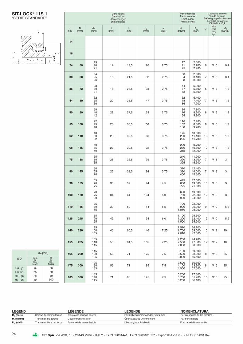
24 SIT SpA Via Watt, 15 - 20143 Milan - ITALY - T+39.02891441 F+39.0289181327 - [email protected] - SIT-LOCK® (031.04)
dW [mm]
from de
über desde
to à
bis hasta
SIT-LOCK® 11S.1“SERIE STANDARD”
LEGEND LÉGENDE LEGENDE NOMENCLATURAMS (daNm) Screws tightening torque Couple de serrage des vis Festzieh-Drehmoment der Schrauben Par de apriete de los tornillos
Mt (daNm) Transmissible torque Couple transmissible Übertragbares Drehmoment Par transmisible
Pax (daN) Transmissible axial force Force axiale transmissible Übertragbare Axialkraft Fuerza axial transmisible
d [mm]
D [mm]
dW[mm]
I [mm]
L [mm]
d2[mm]
e [mm]
Mt[daNm]
Pax[daN]
sizetype Typtipo
MS[daNm]
Performances Performances
Leistungen Prestaciones
Clamping screws Vis de serrage
Befestigungs-SchraubenTornillos de apriete
DIN 931 - 10,9
DimensionsDimensions
Abmessungen Dimensiones
N°
H6 - j6H6 -h6H6 - g6H7 - g6
ISO
14
16
19 17 2.50024 50 20 14 19,5 26 2,75 21 2.700 6 M 5 0,4
21 25 2.900
24 30 2.90030 60 25 16 21,5 32 2,75 34 3.100 7 M 5 0,4
26 38 3.300
28 44 5.00036 72 30 18 23,5 38 2,75 57 5.800 5 M 6 1,2
31 63 5.800
32 62 6.40044 80 35 20 25,5 47 2,75 78 7.400 7 M 6 1,2
36 86 7.700
38 94 7.90050 90 40 22 27,5 53 2,75 116 8.600 8 M 6 1,2
42 138 9.200
42 116 7.90055 100 45 23 30,5 58 3,75 152 8.800 8 M 6 1,2
48 188 9.700
48 175 10.00062 110 50 23 30,5 66 3,75 200 11.100 10 M 6 1,2
52 225 11.700
50 200 9.70068 115 55 23 30,5 72 3,75 260 10.600 10 M 6 1,2
60 315 12.000
55 240 11.90075 138 60 25 32,5 79 3,75 320 13.700 7 M 8 3
65 395 15.500
60 320 12.40080 145 65 25 32,5 84 3,75 390 14.000 7 M 8 3
70 460 15.800
65 475 17.00090 155 70 30 39 94 4,5 600 19.000 10 M 8 3
75 725 21.000
70 690 19.500100 170 75 34 44 104 5,0 750 22.000 12 M 8 3
80 900 24.000
75 720 22.900110 185 80 39 50 114 5,5 900 25.200 9 M10 5,9
85 1.080 26.200
85 1.100 29.600125 215 90 42 54 134 6,0 1.300 32.400 12 M10 5,9
95 1.500 35.200
95 1.510 36.700140 230 100 46 60,5 146 7,25 1.760 39.600 10 M12 10
105 2.010 42.500
105 2.200 44.700155 265 110 50 64,5 165 7,25 2.500 47.800 12 M12 10
115 2.800 50.900
115 3.100 59.500165 290 120 56 71 175 7,5 3.500 63.000 8 M16 25
125 3.900 65.500
125 3.600 60.500175 300 130 56 71 185 7,5 4.100 63.900 8 M16 25
135 4.500 67.500
135 5.200 77.800185 330 140 71 86 195 7,5 5.700 81.900 10 M16 25
145 6.200 86.100
18305080
305080500
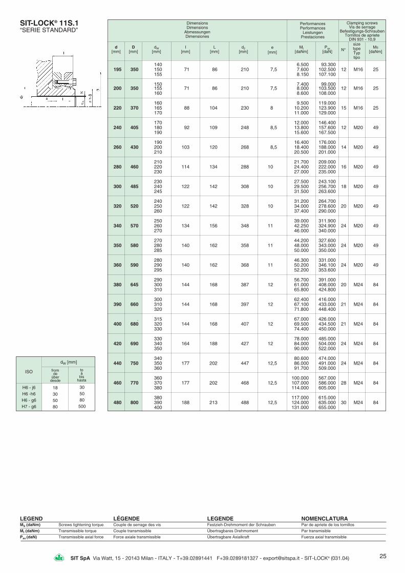
25SIT SpA Via Watt, 15 - 20143 Milan - ITALY - T+39.02891441 F+39.0289181327 - [email protected] - SIT-LOCK® (031.04)
140 6.500 93.300195 350 150 71 86 210 7,5 7.600 102.500 12 M16 25
155 8.150 107.100
150 7.400 99.000200 350 155 71 86 210 7,5 8.000 103.500 12 M16 25
160 8.600 108.000
160 9.500 119.000220 370 165 88 104 230 8 10.200 123.900 15 M16 25
170 11.000 129.000
170 12.000 146.400240 405 180 92 109 248 8,5 13.800 157.600 12 M20 49
190 15.600 167.500
190 16.400 176.000260 430 200 103 120 268 8,5 18.400 188.000 14 M20 49
210 20.500 201.000
210 21.700 209.000280 460 220 114 134 288 10 24.400 222.000 16 M20 49
230 27.000 235.000
230 27.500 243.100300 485 240 122 142 308 10 29.500 256.700 18 M20 49
245 31.500 263.600
240 31.200 264.700320 520 250 122 142 328 10 34.000 278.600 20 M20 49
260 37.400 290.000
250 39.000 311.900340 570 260 134 156 348 11 42.250 324.900 24 M20 49
270 46.000 340.000
270 44.200 327.600350 580 280 140 162 358 11 48.000 343.000 24 M20 49
285 50.000 350.000
280 46.300 331.000360 590 290 140 162 368 11 50.200 346.100 24 M20 49
295 52.200 353.600
290 56.700 391.000380 645 300 144 168 387 12 61.000 408.000 20 M24 84
310 65.800 424.800
300 62.400 416.000390 660 310 144 168 397 12 67.100 433.000 21 M24 84
320 71.800 448.400
. 315 67.000 426.000400 680 320 144 168 407 12 69.500 434.500 21 M24 84
330 74.400 450.000
330 78.000 485.000420 690 340 164 188 427 12 84.000 504.000 24 M24 84
350 90.000 522.000
340 80.600 474.000440 750 350 177 202 447 12,5 86.000 491.000 24 M24 84
360 91.700 509.000
360 100.000 567.000460 770 370 177 202 468 12,5 107.000 586.000 28 M24 84
380 114.000 605.000
380 117.000 615.000480 800 390 188 213 488 12,5 124.000 635.000 30 M24 84
400 131.000 655.000
SIT-LOCK® 11S.1“SERIE STANDARD”
LEGEND LÉGENDE LEGENDE NOMENCLATURAMS (daNm) Screws tightening torque Couple de serrage des vis Festzieh-Drehmoment der Schrauben Par de apriete de los tornillos
Mt (daNm) Transmissible torque Couple transmissible Übertragbares Drehmoment Par transmisible
Pax (daN) Transmissible axial force Force axiale transmissible Übertragbare Axialkraft Fuerza axial transmisible
d[mm]
D[mm]
dW[mm]
I [mm]
L [mm]
d2[mm]
e [mm]
Mt[daNm]
Pax[daN]
sizetype Typtipo
MS
[daNm]
Performances Performances
Leistungen Prestaciones
Clamping screws Vis de serrage
Befestigungs-SchraubenTornillos de apriete
DIN 931 - 10,9
DimensionsDimensions
Abmessungen Dimensiones
N°
dW [mm]
from de
über desde
to à
bis hasta
H6 - j6H6 -h6H6 - g6H7 - g6
ISO
18305080
305080500

26 SIT SpA Via Watt, 15 - 20143 Milan - ITALY - T+39.02891441 F+39.0289181327 - [email protected] - SIT-LOCK® (031.04)
SIT-LOCK® 11S.2“SERIE PESANTE”
LEGEND LÉGENDE LEGENDE NOMENCLATURAMs (daNm) Screws tightening torque Couple de serrage des vis Festzieh-Drehmoment der Schrauben Par de apriete de los tornillos
Mt (daNm) Transmissible torque Couple transmissible Übertragbares Drehmoment Par transmisible
Pax (daN) Transmissible axial force Force axiale transmissible Übertragbare Axialkraft Fuerza axial transmisible
d[mm]
D[mm]
dW[mm]
I [mm]
L [mm]
d2[mm]
e [mm]
Mt[daNm]
Pax [daN]
sizetype Typtipo
MS[daNm]
Performances Performances
Leistungen Prestaciones
Clamping screws Vis de serrage
Befestigungs-SchraubenTornillos de apriete
DIN 931 - 10,9
DimensionsDimensions
Abmessungen Dimensiones
85 1.500 35.500125 215 90 55 65 129 5 1.750 38.800 10 M12 10
95 2.000 42.200
95 2.060 43.300140 230 100 60 74 144 7 2.350 46.900 12 M12 10
105 2.650 50.000
105 2.860 55.000155 265 110 66 80 164 7 3.250 59.000 15 M12 10
115 3.640 63.000
115 4.100 74.000165 290 120 72 88 174 8 4.600 78.500 10 M16 25
125 5.070 81.500
125 4.700 75.000175 300 130 72 88 184 8 5.200 79.500 10 M16 25
135 5.700 84.000
135 7.200 110.000185 330 140 92 112 194 10 7.800 115.000 14 M16 25
145 8.600 120.000
140 7.500 107.500195 350 150 92 112 199 10 8.800 118.000 14 M16 25
155 9.600 123.500
145 8.500 117.000200 350 150 92 112 204 10 9.250 123.000 15 M16 25
155 10.000 129.000
160 12.700 159.000220 370 165 114 134 224 10 13.600 165.000 20 M16 25
170 14.650 172.000
170 15.500 182.000240 405 180 120 144 244 12 17.600 196.000 15 M20 49
190 19.800 208.000
190 21.300 226.000260 430 200 136 160 265 12 24.000 242.000 18 M20 49
210 26.800 258.000
210 28.500 274.000280 460 220 148 172 285 12 32.000 291.000 21 M20 49
230 35.500 309.000
230 34.100 296.000300 485 240 152 176 305 12 37.600 313.000 22 M20 49
245 39.400 321.500
240 37.850 315.000320 520 250 160 184 325 12 41.500 332.500 24 M20 49
260 45.100 347.000
250 48.950 391.000340 570 260 176 200 345 12 53.000 407.500 21 M24 84
270 57.800 427.500
270 55.600 412.200350 580 280 176 200 355 12 60.400 432.000 21 M24 84
285 62.900 441.500
280 61.200 437.000360 590 290 180 204 365 12 66.300 457.000 22 M24 84
295 68.900 467.000
290 61.800 427.000380 645 300 180 204 387 12 66.800 445.500 22 M24 84
310 71.900 464.500
300 70.800 471.500390 660 310 188 212 397 12 76.200 491.000 24 M24 84
320 81.450 509.000
315 76.500 485.500400 680 320 188 212 407 12 78.800 492.700 24 M24 84
330 84.500 512.500
330 99.900 605.500420 690 340 214 238 427 12 106.800 628.500 30 M24 84
350 114.000 651.500
340 105.800 623.000440 750 350 224 252 448 14 113.000 646.000 24 M27 125
360 120.400 669.000
360 132.000 744.000460 770 370 224 252 468 14 142.000 770.000 28 M27 125
380 150.000 795.000
N°
dW [mm]
from de
über desde
to à
bis hasta
H6 - j6H6 -h6H6 - g6H7 - g6
ISO
18305080
305080500

27SIT SpA Via Watt, 15 - 20143 Milan - ITALY - T+39.02891441 F+39.0289181327 - [email protected] - SIT-LOCK® (031.04)
SIT-LOCK® 11S.3“SERIE LEGGERA”
LEGEND LÉGENDE LEGENDE NOMENCLATURAMS (daNm) Screws tightening torque Couple de serrage des vis Festzieh-Drehmoment der Schrauben Par de apriete de los tornillos
Mt (daNm) Transmissible torque Couple transmissible Übertragbares Drehmoment Par transmisible
Pax (daN) Transmissible axial force Force axiale transmissible Übertragbare Axialkraft Fuerza axial transmisible
d[mm]
D[mm]
dW[mm]
I [mm]
L [mm]
d2[mm]
e [mm]
Mt[daNm]
Pax[daN]
sizetype Typtipo
MS[daNm]
Performances Performances
Leistungen Prestaciones
Clamping screws Vis de serrage
Befestigungs-SchraubenTornillos de apriete
DIN 931 - 10,9
DimensionsDimensions
Abmessungen Dimensiones
95 1.055 22.000125 185 100 39 51 129 6 1.210 24.000 10 M10 5.9
105 1.380 26.000
110 1.480 26.500140 220 120 39 51 144 6 1.864 31.000 12 M10 5.9
125 2.050 32.500
130 2.400 36.500155 245 135 39 51 159 6 2.640 39.000 15 M10 5.9
140 2.900 41.000
135 3.200 47.500165 260 140 46 62 169 8 3.520 50.000 10 M12 10
145 3.850 53.000
145 3.900 53.500175 275 150 46 62 179 8 4.240 56.000 10 M12 10
155 4.600 59.000
155 4.660 60.000185 295 160 46 62 189 8 5.030 62.500 14 M12 10
165 5.400 65.000
165 6.300 76.000195 315 170 56 72 199 8 6.770 79.500 14 M12 10
175 7.250 82.500
175 7.400 85.000200 330 180 56 72 204 8 7.950 89.000 15 M12 10
185 8.450 91.500
180 8.280 92.000220 345 190 66 84 224 9 9.350 98.000 20 M16 25
200 10.500 105.500
200 11.300 113.500240 370 210 66 84 244 9 12.750 121.000 15 M16 25
215 13.450 125.000
220 14.900 135.000260 395 230 72 92 265 10 16.500 143.500 18 M16 25
235 17.300 147.500
230 17.100 148.500280 425 240 84 104 285 10 18.900 157.000 21 M16 25
250 20.800 166.000
250 21.500 172.000300 460 260 84 104 305 10 23.400 180.000 22 M16 25
270 25.500 189.000
270 26.000 194.000320 495 280 84 106 325 11 28.400 203.000 24 M16 25
290 30.600 212.500
290 30.000 207.000340 535 300 84 106 345 11 32.440 216.000 21 M16 25
305 33.700 221.000
300 37.200 248.500350 545 305 100 122 355 11 38.500 254.000 21 M20 49
310 40.000 259.000
300 36.000 240.000360 555 310 100 122 365 11 38.800 250.000 22 M20 49
320 41.500 259.000
320 43.500 272.000380 585 325 112 136 387 12 45.100 278.000 22 M20 49
330 46.700 283.500
330 50.500 306.000390 595 340 112 136 397 12 54.000 317.500 24 M20 49
350 57.700 329.500
340 55.000 322.500400 615 350 112 136 407 12 58.700 336.000 24 M20 49
360 62.600 348.000
350 57.800 330.000420 630 360 120 144 427 12 61.700 342.500 30 M20 49
370 65.500 354.500
370 67.700 366.000440 660 380 120 144 447 12 71.900 378.500 24 M20 49
390 76.200 391.000
390 84.000 432.000460 685 400 132 158 468 13 89.000 446.000 28 M20 49
410 93.500 458.000
N°
dW [mm]
from de
über desde
to à
bis hasta
H6 - j6H6 -h6H6 - g6H7 - g6
ISO
18305080
305080500
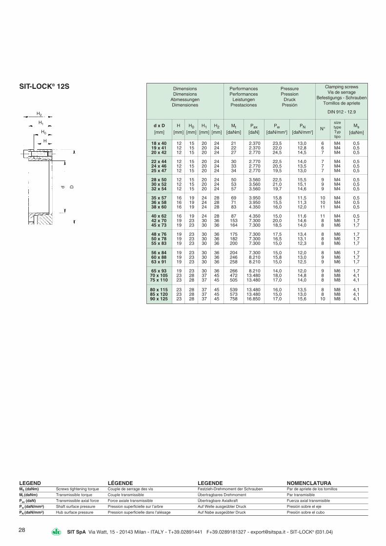
28 SIT SpA Via Watt, 15 - 20143 Milan - ITALY - T+39.02891441 F+39.0289181327 - [email protected] - SIT-LOCK® (031.04)
LEGEND LÉGENDE LEGENDE NOMENCLATURAMS (daNm) Screws tightening torque Couple de serrage des vis Festzieh-Drehmoment der Schrauben Par de apriete de los tornillos
Mt (daNm) Transmissible torque Couple transmissible Übertragbares Drehmoment Par transmisible
Pax (daN) Transmissible axial force Force axiale transmissible Übertragbare Axialkraft Fuerza axial transmisible
Pw (daN/mm2) Shaft surface pressure Pression superficielle sur l’arbre Auf Welle ausgeübter Druck Presión sobre el eje
PN (daN/mm2) Hub surface pressure Pression superficielle dans l’alésage Auf Nabe ausgeübter Druck Presión sobre el cubo
SIT-LOCK® 12S DimensionsDimensions
AbmessungenDimensiones
PerformancesPerformances
LeistungenPrestaciones
PressurePression
DruckPresión
Clamping screwsVis de serrage
Befestigungs - SchraubenTornillos de apriete
DIN 912 - 12.9
d x D H H0 H1 H2 Mt Pax Pw PN[mm] [mm] [mm] [mm] [mm] [daNm] [daN] [daN/mm2] [daN/mm2]
N°sizetypeTyptipo
Ms
[daNm]
18 x 40 12 15 20 24 21 2.370 23,5 13,0 6 M4 0,519 x 41 12 15 20 24 22 2.370 22,0 12,8 6 M4 0,520 x 42 12 15 20 24 27 2.770 24,5 14,5 7 M4 0,5
22 x 44 12 15 20 24 30 2.770 22,5 14,0 7 M4 0,524 x 46 12 15 20 24 33 2.770 20,5 13,5 7 M4 0,525 x 47 12 15 20 24 34 2.770 19,5 13,0 7 M4 0,5
28 x 50 12 15 20 24 50 3.560 22,5 15,5 9 M4 0,530 x 52 12 15 20 24 53 3.560 21,0 15,1 9 M4 0,532 x 54 12 15 20 24 57 3.560 19,7 14,6 9 M4 0,5
35 x 57 16 19 24 28 69 3.950 15,8 11,5 10 M4 0,536 x 58 16 19 24 28 71 3.950 15,5 11,3 10 M4 0,538 x 60 16 19 24 28 83 4.350 16,0 12,0 11 M4 0,5
40 x 62 16 19 24 28 87 4.350 15,0 11,6 11 M4 0,542 x 70 19 23 30 36 153 7.300 20,0 14,6 8 M6 1,745 x 73 19 23 30 36 164 7.300 18,5 14,0 8 M6 1,7
48 x 76 19 23 30 36 175 7.300 17,5 13,4 8 M6 1,750 x 78 19 23 30 36 182 7.300 16,5 13,1 8 M6 1,755 x 83 19 23 30 36 200 7.300 15,0 12,3 8 M6 1,7
56 x 84 19 23 30 36 204 7.300 15,0 12,0 8 M6 1,760 x 88 19 23 30 36 246 8.210 15,8 13,0 9 M6 1,763 x 91 19 23 30 36 258 8.210 15,0 12,5 9 M6 1,7
65 x 93 19 23 30 36 266 8.210 14,0 12,0 9 M6 1,770 x 105 23 28 37 45 472 13.480 18,0 14,8 8 M8 4,175 x 110 23 28 37 45 505 13.480 17,0 14,0 8 M8 4,1
80 x 115 23 28 37 45 539 13.480 16,0 13,5 8 M8 4,185 x 120 23 28 37 45 573 13.480 15,0 13,0 8 M8 4,190 x 125 23 28 37 45 758 16.850 17,0 15,6 10 M8 4,1
H2
H1
H0
H
d D

29SIT SpA Via Watt, 15 - 20143 Milan - ITALY - T+39.02891441 F+39.0289181327 - [email protected] - SIT-LOCK® (031.04)
14 x 25 32 20 30 6,4 900 8,5 4,5 KM4 9,515 x 25 32 20 30 7 900 8 4,5 KM4 9,516 x 25 32 20 30 7,3 900 7,5 4,5 KM4 9,5
17 x 25 32 20 32 8 900 7 4,5 KM4* 16*18 x 30 32 20 32 8,3 900 6,5 4 KM4* 16*19 x 30 38 20 32 10,5 1.100 7,5 4,5 KM5 16
20 x 30 38 20 32 11,2 1.100 7 4,5 KM5 1622 x 35 45 25 36 16,3 1.400 7 4,5 KM6 2224 x 35 45 25 36 17,8 1.400 6,5 4,5 KM6 22
25 x 35 45 25 36 18,5 1.400 6 4,5 KM6 2228 x 40 52 30 42 25 1.700 5,5 4 KM7 3430 x 40 52 30 42 27 1.700 5 4 KM7 34
32 x 45 58 30 44 35 2.100 6 4,5 KM8 4835 x 45 58 30 44 39 2.100 5,5 4,5 KM8 4838 x 50 65 30 45 50 2.600 6 4,5 KM9 68
40 x 50 65 30 45 52 2.600 5,5 4,5 KM9 6842 x 55 70 30 46 68 3.000 6 5 KM10 8745 x 55 70 30 46 68 3.000 6 5 KM10 8748 x 60 75 30 46 84 3.500 6 5 KM11 97
50 x 60 75 30 46 88 3.500 6 5 KM11 9755 x 65 80 30 46 103 3.700 6 5 KM12 11060 x 70 85 30 52 136 4.500 6,5 5,5 KM13 130
Dimensions Dimensions
AbmessungenDimensiones
PerformancesPerformances
LeistungenPrestaciones
PressurePression
DruckPresión Nut
Frein d’ecrouRingmutter
Tuerca
Ms[daNm]
d x D[mm]
D1[mm]
H[mm]
B[mm]
Mt[daNm]
Pax[daN]
PW[daN/mm2]
PN[daN/mm2]
SIT-LOCK® 13S
LEGEND LÉGENDE LEGENDE NOMENCLATURAMS (daNm) Screws tightening torque Couple de serrage des vis Festzieh-Drehmoment der Schrauben Par de apriete de los tornillos
Mt (daNm) Transmissible torque Couple transmissible Übertragbares Drehmoment Par transmisible
Pax (daN) Transmissible axial force Force axiale transmissible Übertragbare Axialkraft Fuerza axial transmisible
PW (daN/mm2) Shaft surface pressure Pression superficielle sur l’arbre Auf Welle ausgeübter Druck Presión sobre el eje
PN (daN/mm2) Hub surface pressure Pression superficielle dans l’alésage Auf Nabe ausgeübter Druck Presión sobre el cubo
Note - SIT-LOCK® 13S is subject to disas-sembly difficulties owing to the particulartaper angle.So, it is preferable to use the standard typeSIT-LOCK® 9, if the transmittable torque issufficient for the application, as it can bedisassembled very easily.
Remarque - Le type SIT-LOCK® 13S est sujetà des difficultés de démontage à cause del’angle du moyeu. Il est préférable d’utiliserles types 9 si le couple transmissible est suffi-sant.
Anmerkung - Beim Ausbau des SIT-LOCK®
13S gibt es Schwierigkeiten wegen derbesonderen Kegeligkeit.Es ist deshalb ratsam, den Standardtyp SIT-LOCK® 9 zu benutzen, aber nur, wenn dasübertragbare Drehmoment genügend ist. Esist nämlich einfacher, den SIT-LOCK® 9auszubauen.
Nota - El tipo SIT-LOCK® 13S presenta difi-cultades para desmontaje debido al ángulode conicidad.Es por ello que recomendamos usar el tipostandart SIT-LOCK® 9 siempre que sea posi-ble.
(*) Without safety ring Sans anneau de securité Ohne Sicherungring Sin anillo de siguridad
Self-centering Auto-centré Selbstzentrierend Autocentrante