catalog v10 t ools and equipment for automotive workshops · t ools and equipment for automotive...
TRANSCRIPT

Ludwig Hunger GmbHMailing address: Office address:
Postfach 70 09 60 Gräfelfinger Str. 146 Fax +49 89 7091 2681309 München 81375 München Tel. +49 89 7091 0Germany Germany
E-mail: info@ludwig-hunger de
Catalog V10
Tools and Equipmentfor Automotive Workshops

ExperiencePerformance
Quality
HUNGER - a company with experience - specializing in themanufacture of precision tools and valve service equipmentfor many years - and with the most comprehensive range ofvalve service equipment.
Years ago, HUNGER pioneered precision valve and valveseat refacing systems which have been further developedand refined until we have the present high performanceequipment.
The qualities of HUNGER equipment are derived from wor-king in very close cooperation with leading engine manufac-turers and the research and experience gained by HUN-GER in over 60 years of precision equipment manufacture.
HUNGER equipment has been tested and approved by lea-ding engine manufacturers and is being used for high per-formance work throughout the world. Today´s exacting tole-rances and finishes call for HUNGER equipment.
You can rely on HUNGER.
HUNGER manufactures also a comprehensive range ofvalve and valve seat refacing machines for servicing thevalves and valve seats of large marine and stationary dieselengines.Please feel free to ask for the HUNGER Marine Catalog.

Catalog V10 - 1 -
Contents
PageHunger Valve Seat Refacing 2
Valve Seat Refacing Systems: Type VDS 1A for Seats from 14 to 60 mm diam. 3 - 16
Parts - Accessories 4 - 5Sets 6Pilots Series VD1 7 - 8Cutters 9 - 16
Type VDS 2 for Seats from 30 to 90 mm diam. 17 - 19Parts - Accessories - Sets 18Pilots Series VD2 20Drehmeißel 21 - 22
Type VD 2 for Seats from 30 to 90 mm diam. 23 - 25Parts - Accessories - Sets 24 - 25
Steady 26
Counterbore Refacing Systems: Type RDS 1 & RDS 2 27 - 30
Parts - Accessories 28 - 29Cutters for RDS 30
Cylinder Head Stands:ZBZ 1 Cylinder Head Work Center 31K2000 Cylinder Head Stand 32 - 33ZSB Cylinder Head Stand 34 - 35
Valve Refacing Machines VKS 16 Valve Grinding Machine 36 - 37VKM 1A Valve Grinding Machine 38 - 39VKDR 1 & VKDR 2 Lathe-type Valve Refacing Machine 40 - 41
Valve Guide Tool Kit 42 - 43
Checking Equipment 44
Valve Guide ReamersExpanding Valve Guide Reamers Type V 45 - 46Solid Valve Guide Reamers Type VR 47
Expanding Reamers for WorkshopsExpanding Reamers Type D 48Expanding Reamers Type E 49Expanding Reamers Type Typ K 50Expanding Reamers Type Typ U 51
Line Boring Equipment 52 - 56Expanding Shell Reamers Type Type H 53Tool Bars and Tool Bar Guides 54Supporting Fixture for Tool Bars 55Boring Heads - Feed Devices 56

- 2 - Hunger Valve Seat Refacing
Details
The Hunger Valve Seat Refacing Method, the superior alternative to grinding and form cutting.
Working Principle:The Hunger VD refaces the valve seat ina lathe-type facing action.
The valve seat is refaced to the presetdepth by the simultaneous application ofboth a rotary and a transverse feed moti-on to the single point carbide cutter.
While the single point carbide cutter rota-tes in a circle around the valve seat, afeed gear mechanism ensures a conti-nuous outward transverse feed motionunder the proper seat angle.
This angle is defined by an inclined slide-way in the exchangeable adapter head.
Hunger machining eliminates the highand low spots normal to surface grindingor form cutting.
Handling:Operation is straightforward.
No setting gauges, no time consumingmeasurements or guesswork whenmounting the cutter and setting up the VDon pilot.
First, lock the pilot in the valve guide.
Then lower VD over the pilot and positionthe cutter in front of the inner edge of thevalve seat.
Turn micrometer infeed to set the desireddepth of cut.
Rotate VD with handle to reface the valveseat in a lathe-type refacing action.
Advantages:The Hunger VD refaces the valve seat inflawless concentric patterns, providing thebest surface texture for a complete valveseal.
The Hunger VD refaces all types of seatswithin a very broad diameter range.Carbide tipped cutters or cutters withindexable carbide insert handle seat materi-als from cast iron to stellite.
Cutters are availabe for both seat refacingand seat narrowing by machining an outerand/ or inner correction with the primaryand/or secondary cutting edge.
All carbide tipped cutters can be resharpe-ned on standard tool sharpeners.
Roundness, concentricity and surface finishof the refaced seat are within manufacturers´secifications.

VDS 1A - 3 -
Valve Seat Refacing System
Recommendedby the leading enginemanufacturers
Application:MotorcyclesCarsLight trucks & commercian vehicles
Capacity:Valve Seat Diameter 14 - 60 mmValve Seat Angle 45°, 35°. 30°,
25°, 20°, 15° & 0°
Hunger VDS 1AThe modular sytem for
refacing valve seats
The first choiceof professionals

- 4 - VDS 1A
Parts and Accessories
Item. Description Part No.
1. VDS 1A Basic Unit 234 11 002The gear head of the basic unit is designed to receive anadapter head for the respective seat angle.
2. Adapter HeadsEach adapter head includes a tool slide which is guided underan angle corresponding to the valve seat angle.D1/45 Adapter Head for 45° seat angle 234 11 120D1/35 Adapter Head for 35° seat angle 234 14 120D1/30 Adapter Head for 30° seat angle 234 12 120D1/25 Adapter Head for 25° seat angle 234 15 120D1/20 Adapter Head for 20° seat angle 234 17 120D1/15 Adapter Head for 15° seat angle 234 13 120D1/0 Adapter Head for 0° angle 234 19 120
Complete Refacing Units:consisting of basic unit and mounted adapter headVDS 1A/45 Refacing Unit for 45° seat angle 236 21 000VDS 1A/35 Refacing Unit for 35° seat angle 236 24 000VDS 1A/30 Refacing Unit for 30° seat angle 236 22 000VDS 1A/20 Refacing Unit for 25° seat angle 236 25 000VDS 1A/20 Refacing Unit for 20° seat angle 236 27 000VDS 1A/15 Refacing Unit for 15° seat angle 236 23 000VDS 1A/0 Refacing Unit for 0° angle 236 29 000
3. Pilots pages 7 - 8VD1 Pilots to be locked in the valve guide are requiredto align the refacing unit in centerline with the valve guide.
4. Cutters4.1 Cutters for 45°, 35°, 30°, 25° & 20° adapter heads pages 10 - 154.2 Cutters for 15° adapter head page 154.3 Cutters for 0° adapter head page 30
5. Steady (page 26) 216 55 500The steady stabilizes the refacing unit justbelow the crank handle.
6. Service ToolsSrewdriver hex 3mm for mounting adapter head 863 19 315Srewdriver hex 4mm for mounting cutter 863 20 045Srewdriver hex 6mm for setting up steady 863 20 068Brush for cleaning valve guide 865 01 001Tommy bars for mounting pilots page 8
7. Storage casesStorage case type 1A 236 90 001including insert for one refacing unit, adapter head,pilots, cutters and service tools.Storage case type 1B 236 90 002including insert for two refacing units, adapter head,pilots, cutters and service tools.

VDS 1A - 5 -
Parts and Accessories
A15
x
15°
20°35° 30°45° 25°
0°
BR
1. Basic Unit
5. Steady
7. Storage Case6. Service Tools
4.1 Cutters
4.3 Cutters4.2 Cutters
3. Pilots
2. AdapterHeads

- 6 - VDS 1A
Valve Seat Refacing Kits
VDS 1A Kits are available to match the various requirements.Each kit contains all the items needed in a storage case.The storage case has space for additional pilots and cutters so that the kit can beupdated, if new or additional engines are to be serviced.Hunger uses information supplied by various sources to keep the contents of the kitsup to date. As specifications are liable to change without prior notice Hunger cannotbe held responsible for inaccuracies which may occur from time to time.In addition to the kits listed below Hunger supplies also kits as specified by thecustomer.
Description Part No. Seat angle Remarks
Basic Kit I 236 03 137 45° The low cost starting kit for 45° seatsBasic Kit II 236 03 296 45°&30° The low cost starting kit for 45° & 30° seatsStandard Kit 236 03 100 45° The complete kit for 45° seatsMaster Kit 236 03 300 45°&30° The complete kit for 45° & 30° seatsMotorcycle Kit 236 03 193 45° The complete kit for motorcyclesTractor Kit 236 03 117 45° The complete kit for tractorsUniversal Kit 217 03 200 45°&30° The complete kit for cars and commercial
vehicles, includes also the VD2 unit
Description Part No. Seat Angle
Alfa Romeo 236 03 343 45°&30°BMW cars 236 03 184 45°BMW motorcycl. 236 04 172 45°BMW universal 236 03 102 45°Citroen 236 03 303 45°&30°Daihatsu 236 03 186 45°Datsun 236 03 158 45°&30°Ducati 236 03 107 45°Fiat / Lancia 236 03 104 45°&30°Ford cars 236 03 105 45°Harley Davidson 236 03 130 45°Hatz 236 03 131 45°Honda m.cycles 236 03 162 45°Hyundai 236 03 314 45°IHC 236 03 133 45°Kawasaki 236 03 194 45°Lada 236 03 179 45°Massey-Ferg. 236 03 136 45°
Description Part No. Seat Angle
Mazda 236 03 161 45°Mercedes cars 236 03 308 45°&30°Mitsubishi 236 03 187 45°Opel 236 03 112 45°Perkins 236 03 588 45°,35°&30°Peugeot 236 03 314 45°&30°Porsche 236 03 713 45°&15°Renault cars 236 03 315 45°&30°Renault trucks 236 03 750 45°&30°Saab 236 03 181 45°Skoda 236 03 144 45°Subaru 236 03 199 45°Suzuki cars 236 03 134 45°Suzuki m.cycles 236 03 129 45°Toyota 236 03 160 45°VW-Audi 236 03 373 45°Volvo cars 236 03 318 45°&30°Yamaha 236 03 183 45°
Special VDS 1A Kits
Universal VDS 1A Kits

VDS 1A - 7 -
Expanding Pilots Series VD1
Expanding Collet Pilot Pilot incl. Spare & add.diameter Ø lengt L size Collet collets
mm mm Part No. Part No.
5,4 - 5,65 35 5/1 216 71 101 216 71 5015,65 - 5,9 35 216 71 506
5,9 - 6,2 35 6/1 216 71 102 216 71 5026,2 - 6,5 35 216 71 5036,4 - 6,65 35 216 71 5046,65 - 6,9 35 216 71 505
6,9 - 7,2 35 7/1 216 75 112 216 75 51242 216 71 112 216 71 512
7,2 - 7,5 35 216 75 51342 216 71 513
7,4 - 7,65 35 216 75 51442 216 71 514
7,65 - 7,9 35 216 75 51542 216 71 515
7,9 - 8,4 38 8/1 216 75 122 216 75 52252 216 71 122 216 71 522
8,4 - 8,9 38 216 75 52352 216 71 523
8,9 - 9,4 44 9/1 216 75 132 216 75 53259 216 71 132 216 71 532
9,4 - 9,9 44 216 75 53359 216 71 533
9,9 - 10,4 48 10/1 216 75 142 216 75 54268 216 71 142 216 71 542
10,4 - 10,9 48 216 75 54368 216 71 543
10,9 - 11,4 48 11/1 216 75 147 216 75 54776 216 71 147 216 71 547
11,4 - 11,9 48 216 75 54876 216 71 548
11,9 - 12,4 56 12/1 216 75 152 216 75 55284 216 71 152 216 71 552
12,4 - 12,9 56 216 75 55384 216 71 553
Pilot shaftdiameter:
9,5mm
Hole dia-meter:
4,5mm
Nut
Ø
L
Collet
Hole dia-meter:
3 or 4,5mm
Expanding pilots are available to fit valve guidesfrom 5,9 to 12,9 mm in diameter.Two or more collets are available for each pilotsize. Collets of different length L are available forpilot sizes 7/1 - 12/1 to achieve perfect cente-ring in case of very short valve guides.
Important:When selecting apilot make surethat the length Lis shorter thanthe length of thevalve guide.
Correct Too long

- 8 - VDS 1A
Solid Pilots
Solid pilots are available especially for small valve guide diameters.A solid pilot has a slow taper to fit exactly the respective valve guide.The following solid pilots are normally available ex stock:
Valve guide diam. Solid Pilotmm Part No.
4,000 216 72 5164,490 216 72 5124,500 216 72 5134,990 216 72 4995,000 216 72 5115,020 216 72 5005,470 216 72 5075,480 216 72 5085,490 216 72 0065,500 216 72 5025,510 216 72 0055,520 216 72 5095,530 216 72 0036,000 216 72 0017,000 216 72 0118,000 216 72 021
Tommy Bars
Tommy bars are required for mounting and demounting expandingpilots and for withdrawing solid pilots from the valve guides.
Description Part No. Fitting in
Tommy Bar Ø 3 mm 216 91 300 Pilot nut sizes 5 - 8Tommy Bar Ø 4,5 mm 216 91 450 Pilot shaft VD1 and
pilot nut sizes 9 - 16Tommy Bar Ø 6 mm 217 91 600 Pilot shaft VD2 and
pilot nut sizes 17 - 18

VDS 1A - 9 -
Cutters
In addition to single point refacing of the valve seat the primary and/or secondary cut-ting edges of this cutter type are designed for machining the top and/or bottom edgesof the valve seat under the proper angle.
1. Cutters for seat refacing and correction
This type is designed for cutting only thevalve seat surface.The cutting edge geometry of this cuttertype is optimized to cut hard-to-face seatmaterials properly.
This type of cutter is designed for correc-ting only.The angle of correction is defined by theproper inclination of the cutting edge.Cutters 24, 24M, 30, C42, C82, E, E2, F,F1, F4, F5, F10, G and H belong to thistype of cutters.
This type of cutter is designed for cuttinga groove into the valve seat ring so that asuitable tool can be applied to remove thevalve seat ring.Cutters C6 und C6.1 belong to this type ofcutters.
Cutters of differnt length, width and cutting geometry are available to cut valve seats ofdiffernt size, shape and location.
2. Cutters for seat refacing only
3. Cutters for correction only
4. Cutters for cutting grooves
C6
A
Cutting a groove
1
Seat refacing Top correction Bottom correction
α β γ
α
Seat refacing
EG
β γ
Top correction Bottom correction

- 10 - VDS 1A
Cutters
Cutters for 45°, 30°, 35°, 25° and 20° adapter heads
1216 64 11 0
22 - 38yes15°75°
surfaceuniversal
6216 64 610
26 - 42yes15°75°
recessedFiat
Lancia
7216 64 211
20 - 36yes15°75°
recessedFiat
LanciaCitroen
Mot.cycle
8216 64 212
22 - 38yes25°75°
recessedHarleyOpel
9216 64 231
28 - 44yes30°75°
recesseduniversal
10216 64 620
28 - 44yes35°75°
surfaceuniversal
11216 64 621
48 - 60yes15°75°
universaluniversal
1M216 64 11 2
20 - 36yes15°75°
surfaceuniversalMercedes
2216 64 130
32 - 48yes15°75°
surfaceuniversal
3216 64 210
22 - 38yes15°75°
recesseduniversal
4216 64 230
32 - 48yes15°75°
recesseduniversal
5216 64 460
32 - 48yes15°75°
recesseduniversal
11M
2
8 9
3 4
5
6
TypeOrder-No.for seat diam. mmRefacing seatsTop correctionBottom correctonSeat locationApplication
Drawn to scale
TypeOrder-No.for seat diam. mmRefacing seatsTop correctionBottom correctonSeat locationApplication
Drawn to scale
7
1110

VDS 1A - 11 -
Cutters
Cutters for 45°, 30°, 35°, 25° and 20° adapter heads
12216 64 622
22 - 38yes30°75°
recessedMazdaOpel
PerkinsToyota
17216 64 626
24 - 40yes15°80°
recessedFord
Renault
18216 64 611
26 - 42yes11°75°
recessedSaab
23M216 64 235
22 - 38yes35°60°
recessedMercedes
24216 64 233
30 - 60no
r=7,5mm
recessed
24M216 62 170
20 - 40no35°
recessedMercedes
25216 64 132
15 - 31yes0°
58°recessedMazdaSuzuki
13216 64 623
32 - 48yes15°60°
recessedBMW
MercedesPeugeot
14216 64 624
20 - 36yes0°60°
recessed
15216 64 625
20 - 36yes15°75°
recessedAudiVW
15M216 64 208
20 - 36yes15°65°
recessedMercedes
16216 64 631
22 - 38yes30°65°
recessedMitsubishi
Toyota
12
TypeOrder-No.for seat diam. mmRefacing seatsTop correctionBottom correctonSeat locationApplication
Drawn to scale
TypeOrder-No.for seat diam. mmRefacing seatsTop correctionBottom correctonSeat locationApplication
Drawn to scale
13 14 15 15M
16
1718 23
M24 24
M25

- 12 - VDS 1A
Cutters
Cutters for 45°, 30°, 35°, 25° und 20° adapter heads
26216 64 627
22 - 38yes20°60°
recessedYamaha
32216 64 215
23 - 41yes15°
-recessedMercedesPorsche
33216 64 216
16 - 32yes30°60°
recessedPorsche
34216 64 217
18 - 34yes30°60°
recessedPorsche
35216 64 218
20 - 36yes25°60°
recessedPorsche
27216 64 214
20 - 36yes30°60°
recessedDatsunMazda
Kawasaki
28216 64 234
25 - 42yes30°60°
recessedDaihatsuDatsunMazda
Kawasaki
29216 64 11 3
22 - 38yes0°65°
surfaceBMW
30216 64 133
16 - 40no-
60°recessed
BMWKawasakiSubaru
31216 64 134
28 - 44yes35°
-recessed
BMWKawasakiSubaru
TypeOrder-No.for seat dia. mmRefacing seatsTop correctionBottom correctonSeat locationApplication
Drawn to scale
TypeOrder-No.for seat dia. mmRefacing seatsTop correctionBottom correctonSeat locationApplication
Drawn to scale
26 27 28 29 30 31
3234 3533
36216 64 636
20 - 36yes15°60°
recessedBMW
36

VDS 1A - 13 -
Cutters
Cutters for 45°, 30°, 35°, 25° und 20° adapter heads
B216 61 130
34 - 54yes
--
surfaceuniversal
C4-2216 69 312
15 - 30no-
60°recesseduniversal
C6216 69 210
27 - 48no--
universalcutting
grooves
C6-1216 69 215
24 - 43no--
universalcutting
grooves
C7216 69 211
15 - 34yes
--
recessedMot.cycles
B1216 61 131
48 - 60yes
--
surfaceuniversal
C216 61 210
20 - 40yes
--
recesseduniversal
C1216 61 560
17 - 37yes
--
recesseduniversal
C4216 69 310
20 - 38yes15°
-recessed
OpelRenaultVolvo
C4-1216 69 311
20 - 38yes30°
-recesseduniversal
TypeOrder-No.for seat dia. mmRefacing seatsTop correctionBottom correctonSeat locationApplication
Drawn to scale
TypeOrder-No.for seat dia. mmRefacing seatsTop correctionBottom correctonSeat locationApplication
Drawn to scale
B B1C
C4
C41
C42
C7
C1
C6
C 6.1
A216 61 11 0
20 - 40yes
--
surfaceuniversal
A1216 61 11 2
25 - 42yes
--
surfaceuniversal
A A1

- 14 - VDS 1A
Cutters
Cutters for 45°, 30°, 35°, 25° und 20° adapter heads
C8-2216 69 214
12 - 30no-
60°recesseduniversal
E2216 62 160
35 - 52no
0° e 30°-
recesseduniversal
F216 62 210
20 - 37no15°
-recesseduniversal
Ford Lada
F1216 62 230
35 - 52no15°
-recesseduniversal
F4216 62 610
20 - 37no30°
-surface
universal
C9216 69 413
14 - 34Ja--
recesseduniversal
D216 61 230
34 - 54Ja--
recesseduniversal
D2216 61 431
24 - 44Ja--
recesseduniversal
D7216 61 232
38 - 58Ja--
recesseduniversal
E216 62 150
20 - 52no15-
recesseduniversal
TypeOrder-No.for seat dia. mmRefacing seatsTop correctionBottom correctonSeat locationApplication
Drawn to scale
TypeOrder-No.for seat dia. mmRefacing seatsTop correctionBottom correctonSeat locationApplication
Drawn to scale
DD2
EE2
F F1 F4
C82
C9
D7
C8216 69 212
17 - 37Ja15°
-recessedMazdaToyota
Mot.cycles
C8-1216 69 213
17 - 37Ja30°
-recesseduniversal
C81
C8

VDS 1A - 15 -
Cutters
Cutters for 45°, 30°, 35°, 25° und 20° adapter heads
Cutters for 15° adapter head
A/15216 61 120
20 - 40surface
universal
B/15216 61 140
38 - 58surface
universal
C/15216 61 220
20 - 40recesseduniversal
D/15216 69 211
38 - 58recesseduniversal
D1/15216 69 212
28 - 48recesseduniversal
TypeOrder-No.for seat dia. mmSeat locationApplication
Drawn to scale
A15
B15
C15
D15
D115
TypeOrder-No.for seat dia. mmRefacing seatsTop correctionBottom correctonSeat locationApplication
Drawn to scale
G216 62 310
20 - 37no-
75°universaluniversal
G
G0216 62 310.1
20 - 37yes0°75°
universaluniversal
G0
H216 62 330
35 - 52no-
75°universaluniversal
H
H1216 62 331
22 - 52no15°60°
universalHarley
H1
F5216 62 231
20 - 37no25°
-recesseduniversal
F10216 62 235
35 - 52no30°
-recessed
HarleyPorsche
F5
F10

- 16 - VDS 1A
Cutters
SC1216 65 110
23 - 43yes
--
surface & recesseduniversal
Part No.216 65 110
216 65 001862 20 004809 71 026863 22 002
SC2216 65 100
28 - 48yes
--
surface & recesseduniversal
Part No.216 65 100
216 65 002862 20 003809 71 025863 22 001
SC5216 65 120
40 - 60yes
--
surface & recesseduniversal
Harley
Part No.216 65 120
216 65 003862 20 003809 71 025863 22 001
SC5
TypePart No.For seat dia. mmSeat refacingTop correctionBottom correction Seat location Application
Scope of supply:Cutterconsisting ofToolholderCutting insertClamping screwTorx screwdriver
Drawn to scale
SC Cutters with indexable insertsfor hard seats
The SC type cutters are furnished with indexable carbide inserts.The indexable inserts are coated with TiN and are specifically provided for cutting thehard seat materials as used in modern engines.If the insert is too dull or chipped, index insert or install a new insert.
Cutters for 45°, 30°, 35°, 25° and 20° adapter heads

VDS 2 - 17 -
Valve Seat Refacing System
Recommendedby the leading engine manufacturers
Application:Trucks & heavy commercial vehiclesLocomotivesMarine & stationary diesel engines
Capacity:Valve seat diameter 30 - 90 mmValve seat angle 45°, 35°. 30°,
25°, 20°, 15° & 0°
Hunger VDS 2The modular heavy-duty system
for refacing valve seats.

- 18 - VDS 2
Parts - Accessories - Kits
Item Decription Part No.
1. VDS 2 Basic Unit 237 10 002The gear head of the basic unit is designed to receive anadapter head for the respective seat angle.
2. Adapter HeadsThe adapter head includes a tool slide which is guided underan angle corresponding to the valve seat angle.D2/45 Adapter Head for 45° seat angle 237 11 145D2/35 Adapter Head for 35° seat angle 237 14 135D2/30 Adapter Head for 30° seat angle 237 12 130D2/25 Adapter Head for 25° seat angle 237 15 125D2/20 Adapter Head for 20° seat angle 237 17 120D2/15 Adapter Head for 15° seat angle 237 13 115D2/0 Adapter Head for 0° angle 234 19 100
Complete Refacing Units:consisting of basic unit and mounted adapter headVDS 2/45 Refacing Unit for 45° seat angle 237 21 000VDS 2/35 Refacing Unit for 35° seat angle 237 24 000VDS 2/30 Refacing Unit for 30° seat angle 237 22 000VDS 2/20 Refacing Unit for 25° seat angle 237 25 000VDS 2/20 Refacing Unit for 20° seat angle 237 27 000VDS 2/15 Refacing Unit for 15° seat angle 237 23 000VDS 2/0 Refacing Unit for 0° angle 237 29 000
3. Pilots page 20A pilot series VD2 is required for aligning the refacing unit
4. Cutters4.1 Cutters for 45°, 35°, 30°, 25° & 20° adapter heads pages 21 - 224.2 Cutters for 15° adapter head page 154.3 Cutters for 0° adapter head page 30
5. Steady (page 26) 216 55 500
6. Service ToolsWrench SW 10 for setting up the refacing unit 863 01 010Screwdriver hex 4mm for mounting cutter 863 20 045Screwdriver hex 6mm for setting up steady 863 20 068Brush for cleaning valve guide 865 01 001Tommy bars for mounting pilots page 8
7. Storage case type 2A 217 90 041
8. KitsEach kit comprises all items for the particular engine make to be serviced.
VDS 2 Kit Iveco Seat angle 25°, 30° & 45° 237 03 156VDS 2 Kit Mercedes Trucks Seat angle 20°, 30° & 45° 217 03 127VDS 2 Kit Scania Seat angle 20°, 30° & 45° 237 03 150VDS 2 Kit Steyr Seat angle 35° & 45° 237 03 001VDS 2 Standards Kit Seat angle 20°, 30° & 45° 237 03 800

VDS 2 - 19 -
Parts and Accessories
BRA15
15°
30° 20°45°
x
35° 25°
0°
1. Basic Unit
5. Steady
7. Storage Case
6. ServiceTools
4.1 Cutter
4.3 Cutter4.2 Cutter
3. Pilot
2. AdapterHeads

- 20 - VDS 2
Expanding Pilots Series VD2
Expanding Collet Pilot Pilot incl. Spare & add.diameter Ø lengt L size Collet collets
mm mm Part No. Part No.
7,9 - 8,4 38 8/2 217 75 122 216 75 52252 217 71 122 216 71 522
8,4 - 8,9 38 216 75 52352 216 71 523
8,9 - 9,4 44 9/2 217 75 132 216 75 53259 217 71 132 216 71 532
9,4 - 9,9 44 216 75 53359 216 71 533
9,9 - 10,4 48 10/2 217 75 142 216 75 54268 217 71 142 216 71 542
10,4 - 10,9 48 216 75 54368 216 71 543
10,9 - 11,4 48 11/2 217 75 147 216 75 54776 217 71 147 216 71 547
11,4 - 11,9 48 216 75 54876 216 71 548
11,9 - 12,4 56 12/2 217 75 152 216 75 55284 217 71 152 216 71 552
12,4 - 12,9 56 216 75 55384 216 71 553
12,9 - 13,4 92 13/2 217 71 157 217 71 55713,4 - 13,9 92 217 71 558
13,9 - 14,4 100 14/2 217 71 162 217 71 56214,4 - 14,9 100 217 71 563
14,9 - 15,4 108 15/2 217 71 167 217 71 56715,4 - 15,9 108 217 71 568
15,9 - 16,4 108 16/2 217 71 172 217 71 57216,4 - 16,9 108 217 71 573
16,9 - 17,9 116 17/2 217 71 076 217 71 576
17,9 - 18,9 116 18/2 217 71 078 217 71 578
Pilot shaftdiameter:14,5 mm
Hole dia-meter:6 mm
Pilotnut
Ø
LCollet
Hole dia-meter:Ø 3, 4,5 or 6 mm
Expanding pilots are available to fit valve guidesfrom 7,9 to 18,9 mm in diameter.Two or more collets are available for each pilotsize. Collets of different length L are available forpilot sizes 8/2 - 12/2 to achieve perfect cente-ring in case of very short valve guides.
mportant:When selecting apilot make surethat the length Lis shorter thanthe length of thevalve guide.
Correct Too long

VDS 2 / VD 2 - 21 -Cutters
Cutters for 45°, 35°, 30°, 25° and 20° adapter headsfor seat refacing and correction
1216 64 11 0
35 - 60yes15°75°
surfaceuniversal
13216 64 623
45 - 90yes15°58°
recessedMercedes
25216 64 132
28 - 60yes0°
58°recessed
MAN
32216 64 215
35 - 80yes15°
-recesseduniversalMercedes
C8216 64 212
28 - 70yes15°
-recesseduniversalMercedes
1M216 64 11 2
30 - 60yes15°75°
surfaceuniversalMercedes
2216 64 130
45 - 90yes15°75°
surfaceuniversal
3216 64 210
35 - 60yes15°75°
recesseduniversal
4216 64 230
45 - 90yes15°75°
recesseduniversal
5216 64 460
45 - 90yes15°75°
recesseduniversal
11M
2
32C8
3 45
13
TypePart No.for seat dia. mmRefacing seatsTop correctionBottom correctonSeat locationApplication
Drawn to scale
TypePart No.for seat dia. mmRefacing seatsTop correctionBottom correctonSeat locationApplication
Drawn to scale
25

- 22 - VDS 2 / VD 2
Cutters
Typ A B C D SC1 SC2Part No. 216 61 110 216 61 130 216 61 210 216 61 230 216 65 110 216 65 100for seat dia. mm 35 - 60 45 - 90 35 - 60 45 - 90 35 - 75 40 - 85Refacing seats yes yes yes yes yes yesTop correction - - - - - -Bottom correction - - - - - -Seat location surface surface recessed recessed universal universalApplication universal universal universal universal universal universal
A B
Type C6 C6.1Part No. 216 69 210 216 69 215for seat dia. mm 36 - 80 29 - 70 *Seat location universal Mercedes
C6
C 6.1
Cutters 45°, 35°, 30°, 25° and 20° adapter headsfor seat refacing only
Cutters for 45°, 35°, 30°, 25° and 20° adapter headsfor cutting a groove into the valve seat ring
Drawn to scale
Drawn to scale
* from 29 mm with 30° adapter head

VD 2 - 23 -
Valve Seat Refacing System
Recommendedby the leading engine manufacturers
Application:Trucks & heavy commercial vehiclesLocomotivesMarine & stationary diesel engines
Capacity:Valve seat diameter 30 - 90 mmValve seat angle 45° & 30°
Hunger VD 2The heavy-duty system
for refacing 45° and 30° valve seats

- 24 - VD 2
Parts - Accessories - Kits
Item.Description Part No.
1. VD 2 Refacing Unit for 45° & 30° Seats 217 21 000
2. Pilots page 20A pilot series VD2 is requirded for aligning the refacingunit in centerline with the valve guide.
3. Cutters pages 21 - 22A wide range of cutters are availablte to matchevery requirement
4. Steady (Seite 26) 216 55 500The steady supports the refacing unit just below the crank handle.
5. Service ToolsWrench SW 10 for setting up the refacing unit 863 01 010Screwdriver hex 4mm for mounting cutter 863 20 045Screwdriver hex 6mm for setting up steady 863 20 068Brush for cleaning valve guide 865 01 001Tommy bars for mounting pilots page 8
6. Storage case type 2A 217 90 041
7. KitsEach kit comprises all items for the particular engine make to be serviced.
VD 2 Kit DAF LKW 217 03 107VD 2 Kit Ford LKW 217 03 126VD 2 Kit MAN 217 03 105VD 2 Standard Kit 217 03 100
Further special kits are available for Deutz, MTU - and Pielstick engines.
The VD 2 features a head including a 45° tool slide and a 30° tool slide guided indovetailed slideways which are inclined under an angle of 45° and 30°, respectively.

VD 2 - 25 -
Parts and Accessories
x
1. VD 2 Valve Seat Refacing Unit
4. Steady
6. Storage Case
5. ServiceTools
3. Cutter2. Pilot

- 26 - VDS 1A-VDS 2-VD 2-RDS
Steady
Item Description Part No.
1. Steady 216 55 500consisting of
1.1 Steady Clamp 216 55 2201.2 Base Member with universal joint and post 216 55 510
2. Conversion Kit for VD1 216 21 700
Conversion Kit for VD2 217 21 700
3. Rapid Clamp 216 55 520
The swivelling guide arm (2) of a refacing unit can be locked in place by means of thesteady which prevents lateral displacement of the refacing unit.
The older types VD 1 and VD 2 refacing units have ball-type guide arms. The ball-type guide arm can be replaced by the more convenient swivelling guide arm.Conversion kits are availabe for the VD 1 and VD 2 models. A new steady clamp (1.1) is required when replacing the ball-type guide arm. We suggest to procure the complete new steady (1) shown above which is more versa-tile than the old steady
A rapid clamp (3) is available to clamp the base member of the steady to the cylinderhead. The rapid clamp includes an adjustable clamping lever.
3
1
2
1.2
1.1
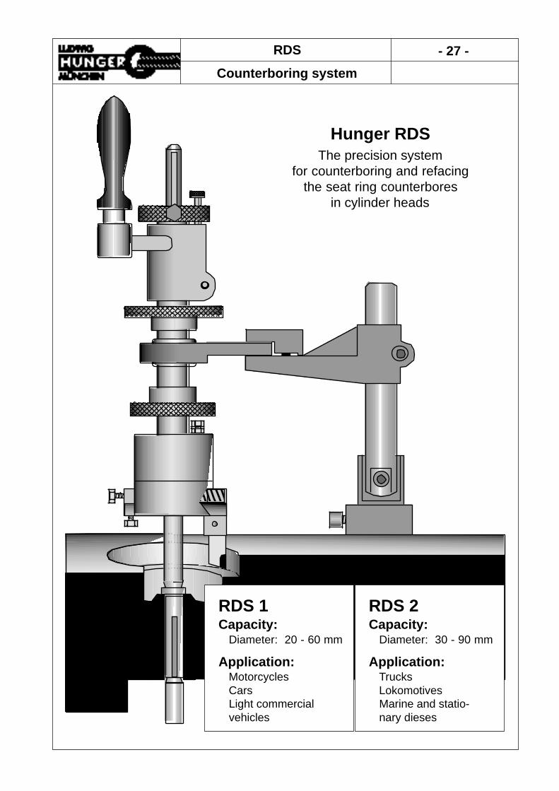
RDS - 27 -
Counterboring system
RDS 1Capacity:
Diameter: 20 - 60 mm
Application:MotorcyclesCarsLight commercialvehicles
RDS 2Capacity:
Diameter: 30 - 90 mm
Application:TrucksLokomotivesMarine and statio-nary dieses
Hunger RDSThe precision system
for counterboring and refacingthe seat ring counterbores
in cylinder heads

- 28 - RDS
Information - Parts - Accessories
Item Description Part No.
1. RDS 1 Unit 219 20 0002. Pilots Series VD1 See pages 7 - 83. Cutters See page 304. Universal Steady See page 265. Service Tools
Wrench (7mm) for setting up RDS 1 863 01 007Hex Key (4mm) for mounting cutter 863 20 045Tommy bars for installing pilots See page 8
6. Storage Case for RDS 1 219 90 044
- RDS 1 Kit 219 00 100including RDS 1 unit, cutter types AR, BR, CR, DRand service tools packed in the sturdy storage case
The Hunger RDS is designed to precision machine the seat ring counterbores in cylin-der heads to produce smooth and closely fitting contact surfaces for new seat inserts.The RDS is equipped for turning inside diameter as well as facing bottom of the seatring counterbores in a lathe-type action with a single point carbide cutter.The RDS is aligned in centerline with the valve guide by means of a pilot which islocked in the valve guide. An universal steady stabilizes the RDS against lateral displa-cement. Pilots and steady furnished with Hunger VD valve seat refacing system alsosuit for the corresponding RDS system.The built-in feed gear mechanism for automatic longitudinal and cross feed of thesingle point cutter eliminates the need for multiple cutter sets and other accessories.The feed rate per revolution of the cutter is 0,06 mm ensuring perfect surface finish.An adjustable stop for the tool slide permits quick selection of the proper sized coun-
Item Description Part No.
1. RDS 2 Unit 220 20 0002. Pilots See page 203. Cutters See page 304. Universal Steady See page 265. Service Tools
Wrench (10mm) for setting up RDS 2 863 01 010Hex Key (4mm) for mounting cutter 863 20 045Tommy bars for installing pilots See page 8
6. Storage Case for RDS 2 220 90 045
- RDS 2 Kit 220 00 100including RDS 2 unit, cutter types AR, BR, CR, DRand service tools packed in the sturdy storage case
Hunger RDS 1 - Order Information
Hunger RDS 2 - Order Information

RDS - 29 -
Parts - Accessories
4. Steady
3. Cutter
5. Service Tools
6. Storage Case
2. Pilot
1. Counterboring Unit

- 30 - RDS, VDS 1A & VDS 2
Cutters
Type AR BR CR DRPart No. 219 61 110 219 61 130 219 61 210 219 61 230for bore dia. mm:
with RDS 1 20 - 37 35 - 60 20 - 37 35 - 60with RDS 2 35 - 60 45 - 90 35 - 60 45 - 90
Seat location surface surface recessed recessed
Drawn to scale
Type ARN BRN CRN DRNPart No. 219 61 120 219 61 132 219 61 213 219 61 232for bore dia. mm:
with RDS 1 20 - 37 35 - 60 20 - 37 35 - 60with RDS 2 35 - 60 45 - 90 35 - 60 45 - 90
Seat location surface surface recessed recessed
Drawn to scale
Cutters for Counterboring and Refacing
These cutters are also required for the adapter heads D1/0° und D2/0° of the VDS 1A und VDS 2 unit for plain refacing
Cutters for cutting grooves
These cutters are designed for cutting a groove into a valve seat ring so that a suitabletool can be applied for removing the seat ring.

ZBZ 1 - 31 -
Cylinder Head Work Center
Application:MotorcyclesCarsCommercial vehicles
ZBZ 1the compact work center
for cleaning andrepairing cylinder heads
When the cylinder head is mountedon the work center the following ope-rations may be performed:
Cleaning the cylinder headRemoving the valvesCleaning the valvesRepairing valve guidesReplacing seat ring insertsRefacing valve seatsMachining valve portsRepairing studsRepairing threadsAssembling the valves.
The cylinder head rotates through360° and can be locked in thosepositions which are most suitable forthe work to be performed.
DimensionsLenght 1500 mmDepth 800 mmHeight 1150 mm
Weight:ZBZ 1 with cylinder head 210 kgstand and wet cleaningZBZ 1with cylinder head 190 kgstand (no wet cleaning)
The cylinder head work center includes theK2000 cylinder head stand mounted on a rigidmetal pan. The storage cabinet below the panhouses the removalbe cleaning fluid storage tankincluding the pump.Shelfes are provided for storing the various repairtools and units.An electric outlet is provided to energize electrictools.
ZBZ 1accomodates cylinder heads up to820 mm long
Order Information:
Description Part No.
ZBZ 1 with cylinder head stand 221 50 200and wet cleaning
ZBZ 1 with cylinder head stand 221 50 250
Accessories for valve head stand see page 33.

- 32 - K2000
Cylinder Head Stand
Recommendedby leading engine manufacturers
Makes assembly procedures and seat refacing fast and easy.360° cylinder head rotatation.
Quickly locks in any position.Includes valve spring lifting equipment.
Application:MotorcyclesCarsTrucks and commercial vehicles
K2000 Cylinder Head Standaccomodates cylinder heads up to 820 mm long
K2000 Dimensions & WeightLength 1170 mmDepth 530 mmHeight 440 - 580 mmNet weight approx. 60 kg
Valve spring lifting equipment

K2000 - 33 -
Cylinder Head Stand
Item Description Part No. Picture
1. K2000 Cylinder Head Stand 221 00 100including a clamp for lockingthe swivelling guide arm ofa VD valve refacing unit, valve spring lifting attachment and valve stop attachment for keeping the valves in place when compressing the valve springs.
2. Electromagnetic Support 221 40 100for locking the swivelling guide armof a VD valve seat refacing unit. Includes a 24 V power supply unitfor connection to 220 - 240 V AC.
3. Work Light 221 90 100including clamping attachmentfor mounting to the head stand.The work light is equipped witha halogen lamp (12V, 20W).Includes a safety transformer forconnection to 220 V AC.
4. Plunger Ø 22mm 221 20 058for compressing valve springslocated in narrow recessessind.
5. Plunger Ø 30 mm 221 20 054for compressing very largevalve springs
6. Items for updating cylinder head standssupplied before 1996:
Swivelling holder 221 20 052
Plunger Ø 26 mm 221 20 056

- 34 - ZSB
Cylinder Head Stand
Hunger ZSB, the universal bench-type stand for cylinderheads up to 720 mm in length.
The cylinder head clamped onto the ZSBcan be rotated by 360° and may be fixed atany desired angular position.Therefore, assembly and disassembly workcan be done with the cylinder head in themost appropriate position.
A valve spring compressing set including ascrew drive mechanism operated by anhandwheel is available as an accessory.
An adjustable valve stop is included in thecompressing set to bear against the valvehead when compressing the valve spring.Both hands are free to retrieve the keeperand to drop the keepers in place.
When using a Hunger VD-type valve seatrefacer, the upper swivelling arm of theVD can be fixed either manually or elec-tro-magnetically.
Dimensions: Length/Width/Heigth 1000/450/600 mmNet Weight: 45 kg
The economical solution for cylinder head assembly and disassembly work as well as valve seat refacing.
380° Cylinder head rotation.Locks in any position.
Optional valve spring compression set.

ZSB Seite 35
Cylinder Head Stand
Item Description Part No. Picture
1. ZSB Cylinder Head Stand 270 00 100for cylinder heads up to720 mm long
2. Universal Support 270 50 050for the valve spring compression set and the mechanical or elelectro-magnetical fixture for locking theswivel arm of a Hunger valve seatrefacing unit in place.
3. Valve Spring Compression Set 270 50 100including a screw-down spindlewith an interchangeable plungerØ 26 mm for compressing standard springs and an adjustable stop bearing against the valve head when compressing the valve spring.
4. Plunger Ø 22mm 221 20 058for small valve springs locatedin deep recessions.
5. Plunger Ø 30 mm 221 20 054for very large valve springs.
6. Adapter Plate 270 55 100for mounting the steady postof the mechanical or electro-magnetical fixture to theuniversal support.
7. Mechanical Fixture 270 65 100for the adapter plate tolock the swivel arm of aHunger valve seat refacingunit in place.
8. Elektromagnetic Fixture 270 60 100including 24 V electromagnet tolock the swivel arm of a Hunger valve seat refacing unit in place.

- 36 - VKS 16
Valve Grinding Machine
Specifications:Grinding Spindle:
Wheel diameter 175 mmWheel speed at 50Hz 2790 min-1
Drive motor 370 WWork Spindle:
Speed at 50Hz 120 min-1
Drive motor 42 WWet Grinding
Coolant capacity 5 lCoolant pump motor 50 W
Dimensions & Weight:Overall width 600 mmOverall depth 650 mmOverall height 480 mmNet weight 98 kg
Application:MotorcyclesCars and Commercial VehiclesMarine and Stationary Diesels
Capacity:Valve stem diameter 3 - 16 mmMax. valve head diameter 120 mm
Hunger VKS 16the affordable machine
for workshops
VKS 16 - 37 -
Valve Grinding Machine
Machine Base:Heavily ribbed cast iron structure forvibration-free performance. Integrated sli-deways for wheelhead traverse andworkhead infeed .Wheelhead:The precision motor grinding spindle ispermanently sealed and lubricated.Workhead:Single precision chuck for perfect valvealignment throughout the large chuckingrange. No collets! The workhead is loca-ted on a swivel plate which can be set tothe required angular position by means ofa widespaced scale.
Dressing Attachment:The dressing attachment is permanentlymounted on the worktable for rapid wheeldressing. Wet Grinding:The baffled coolant tank is easily removedfrom the machine base for cleaning.Coolant is delivered by an industrial typeflood pump. Coolant flow is regulated by avalve.Electric System:Individual grinding spindle motor, workspindle motor and coolant pump motor allcontrolled by switsches grouped in a con-trol box for ease of operation.
Item Description Part No.
VKS 16 Valve Grinding Machine1.1 380-440 V, 3 phase, 50/60 cycles 235 00 3801.2 230-254 V, 3 phase, 50/60 cycles 235 00 230
Standard equipment including grinding wheel, dressingdiamond, wet grinding attachment and service tools.
Option:
2. Work Light 235 90 100including low voltage halogen lamp.
Accessories:
3.1 Valve Stem End Grinding Attachment 235 91 100
3.2 Adjustable Valve Stop 231 40 120for fixing the chucking length of the valve stem.
3.3 Cabinet Stand 231 15 100including shelf and lockable door
Replacement Parts:4.1 Grinding Wheel 861 51 2604.2 Dressing Diamond 861 80 0254.3 Concentrated Coolant 838 80 500
5 Litre Bottle
Order Information

- 38 - VKM 1A
Valve Grinding Machine
Recomendedby leading engine manufacturers
Specifications:Wheelhead:
Wheel diameter 175 mmWheel speed 2790 rpmDrive motor 250 W
Workhead:Work speed 120 rpmDrive motor 50 W
Wet Grinding:Coolant capacity 5 LitersCoolant pump motor 70 W
Dimensions and Weight:Overall length 650 mmOverall width 550 mmOverall height 420 mmNet weight approx. 100 kg
Hunger VKM 1Athe rigid and robust precisionmachine for the professional
Application:MotorcyclesCars and Commercial VehiclesMarine and Stationary Diesels
Capacity:Valve stem diameter 3 - 16 mmMax. valve head diameter 120 mm

VKM 1A - 39 -
Valve Grinding Machine
Item Description Part No.
VKM 1A Valve Grinding Machine1.1 380-440 V 3 phase 50/60 cycles 231 00 0011.2 220-254 V 3 phase 50/60 cycles 231 00 002
Standard equipment including grinding wheel, dressingdiamond, wet grinding attachment and service tools.
Options:2.1 Speed Control 231 40 200
for infinitely adjusting the workspindle speed in therange from 10 to 170 rpm.
2.2 Work Light 231 90 100including low voltage halogen lamp.
2.3 24 V Control Voltage 231 60 100including transformer, contactors, push-buttons and emergency stop.
Accessories:3.1 Valve Stem End Grinding Attachment 231 91 1003.2 Rocker Arm Grinding Attachment 231 91 2003.3 Adjustable Valve Stop 231 40 120
for fixing the chucking length of the valve stem.
Replacement Parts:4.1 Grinding Wheel 861 51 2604.2 Dressing Diamond 861 80 0254.3 Concentrated Coolant 838 80 500
5 Litre bottle
Machine Base:Heavily ribbed cast iron structure forvibration-free performance. Integrated sli-deways for wheelhead infeed andworkhead traverse.Wheelhead:Box type monobloc noted for its excellentvibration dampening characteristics. Theprecision motor grinding spindle is perma-nently sealed and lubricated.Workhead:Single precision chuck for perfect valvealignment throughout the large chuckingrange. No collets! The workhead is loca-ted on a swivel plate which can be set tothe required angular position by means ofa wide-spaced scale.
Dressing Attachment:The dressing attachment is permanentlymounted on the worktable for rapid wheeldressing. Wet Grinding:The baffled coolant tank is easily removedfrom the machine base for cleaning.Coolant is delivered by an industrial typeflood pump. Coolant flow is regulated by avalve.Electric System:Individual grinding spindle motor, workspindle motor and coolant pump motor allcontrolled by switsches grouped in front ofthe wheelhead for ease of operation.

- 40 - VKDR
Valve Refacing Lathes
Model: VKDR 1 Model: VKDR 2
Capacity: Capacity:Valve stem diameter 5 - 14 mm Valve stem diameter 7 - 20 mmValve head diameter 20 - 60 mm Valve head diameter 35 - 90 mm
Application: Application:Motorcycles Commercial vehiclesCars LocomotivesSmall commercial vehicles Marine and stationary diesel engines
Technical particulars Technical particularsRotation speed 180 - 450 RPM Rotation speed 180 - 360 RPMDrive motor 70 W Drive motor 85 WVoltage 220-240V, 1ph, 50-60Hz Voltage 220-240V, 1ph, 50-60HzLength 340 mm Length 470 mmWidth 140 mm Width 320 mmHeight 270 mm Height 270 mmWeight 13 kg Weight 24 kg
Hunger VKDRThe fast and affordablealternative to grinding

VKDR - 41 -
Valve Refacing Lathes
Item Description Part No.
1.1 VKDR 1 Valve Refacing Lathe 203 00 200 -including two cutting inserts.Wired for 230 V single phase.
1.2 VKDR 2 Valve Refacing Lathe 204 00 200 -including two cutting inserts.Wired for 230 V single phase.
2.1 Cutting Insert 213 90 102for hard-faced valves
2.2 Cutting Insert 213 90 103for standard valves
3. Cutters with brazed carbide tipType: Application:
3.1 80/1 Soft valve materials 213 80 2023.2 80/4 Tough valve materials 213 80 2053.3 85 Medium hard materials 213 80 3203.4 90 Hard valve materials 213 80 4213.5 90M Mercedes 213 80 4123.6 90C Caterpillar, Scania 213 80 422
4. Cutting Insert Holder 213 90 000complete with key wrench
5.1 Storage Case for VKDR 1 203 90 000
5.2 Storage Case for VKDR 2 204 90 000 -
VKDR Models are small compact lathesfor valve refacing. More than 10 000 unitshave been sold so far.The unique valve stem chucking systemincludes a selfcentering steady and aspring-loaded floating aligner. The steadyis activated by a weight lever to precisioncenter the valve stem.The tool slide assembly is pivotable toadjust the direction of the transverse feedmotion according to the desired seatangle.The VKDR provides a flawless concentricseating surface texture for a perfect valveseal.
Operation is simple:Insert valve stem through the selfcenteringsteady into the work spindle in contact withthe floating aligner.Release the weight lever of the steady tocenter the valve. Switch on the drive motor, advance the cut-ter to the valve face and then engage thetransverse feed.Refacing is automatic. An adjustable stop halts the transversefeed motion of the cutting tool.The Hunger VKDR is the faster altenativeto grinding.

- 42 - PVM 1
Valve Guide Tool Kit
Removing valve guides from cylinder headInstalling new valve guides in cylinder head
Removing seat ring inserts from cylinder head
The PVM 1 is designed to removeand install valve guides in just a fewminutes.
The PVM 1 is recommended formotorcycle and automotive repairshops.
Operation is as easy as one twothree.With the proper valve guide driverfitted in air hammer, insert driverinto valve guide.Switch on air supply by the mereactuation of supply valve lever.The valve guide is removed orinstallted with ease by the rapidseries of air hammer strokes A soft expendable washer placedonto the driver protects the valveguide from damage
The PVM 1 can be also used forremoving valve seat rings.First a groove is cut into the valveseat ring with a Hunger Valve SeatRefacer.Then the expanding jaws of anadapter are forced into the groove.Thereafter the seat ring is driven outof the cylinder head by applyingstrokes of the air hammer to theadapter.
PVM 1 - 43 -
Valve Guide Tool Kit
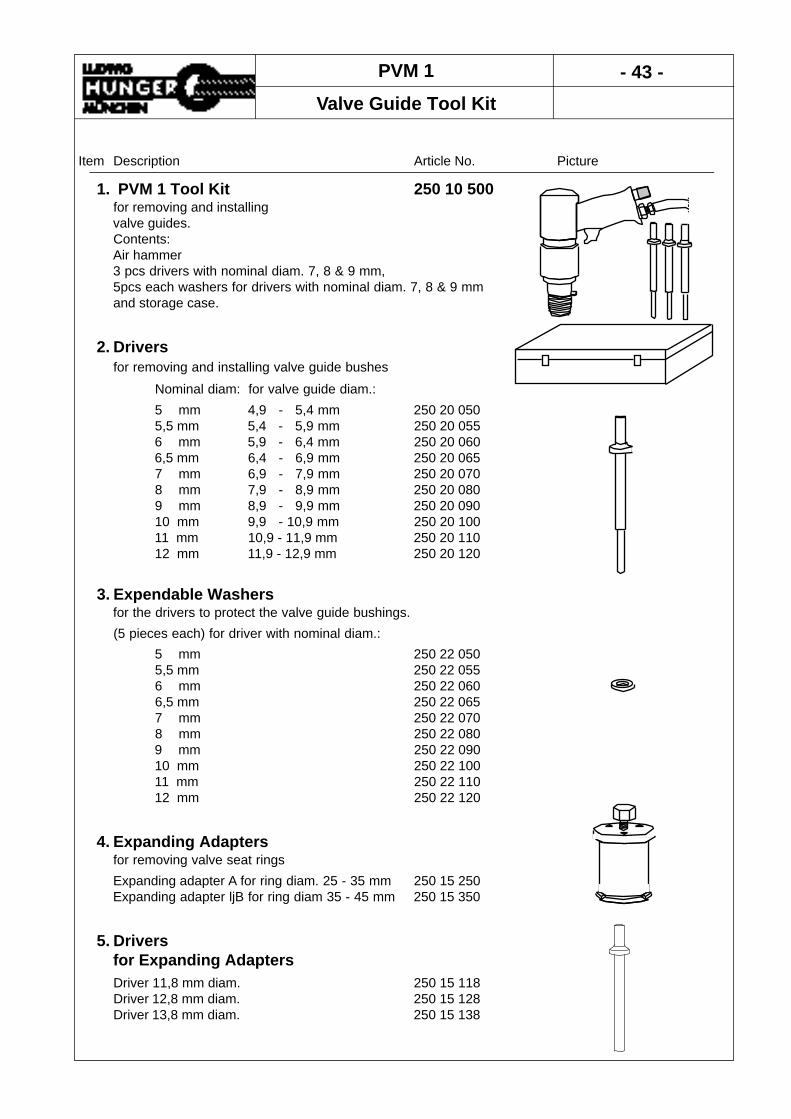
Item Description Article No. Picture
1. PVM 1 Tool Kit 250 10 500for removing and installingvalve guides.Contents: Air hammer 3 pcs drivers with nominal diam. 7, 8 & 9 mm, 5pcs each washers for drivers with nominal diam. 7, 8 & 9 mm and storage case.
2. Drivers for removing and installing valve guide bushes
Nominal diam: for valve guide diam.:
5 mm 4,9 - 5,4 mm 250 20 0505,5 mm 5,4 - 5,9 mm 250 20 0556 mm 5,9 - 6,4 mm 250 20 0606,5 mm 6,4 - 6,9 mm 250 20 0657 mm 6,9 - 7,9 mm 250 20 0708 mm 7,9 - 8,9 mm 250 20 0809 mm 8,9 - 9,9 mm 250 20 09010 mm 9,9 - 10,9 mm 250 20 10011 mm 10,9 - 11,9 mm 250 20 11012 mm 11,9 - 12,9 mm 250 20 120
3. Expendable Washersfor the drivers to protect the valve guide bushings.
(5 pieces each) for driver with nominal diam.:
5 mm 250 22 0505,5 mm 250 22 0556 mm 250 22 0606,5 mm 250 22 0657 mm 250 22 0708 mm 250 22 0809 mm 250 22 09010 mm 250 22 10011 mm 250 22 11012 mm 250 22 120
4. Expanding Adaptersfor removing valve seat rings
Expanding adapter A for ring diam. 25 - 35 mm 250 15 250Expanding adapter ljB for ring diam 35 - 45 mm 250 15 350
5. Driversfor Expanding AdaptersDriver 11,8 mm diam. 250 15 118Driver 12,8 mm diam. 250 15 128Driver 13,8 mm diam. 250 15 138

- 44 - Checking Devices
Checking the valvesfor leakage Operation:
Connect vacuum tester to an air pressureof about 6 bar and use suitable adapterplate to connect the suction inlet of thetester to the respective valve port.Actuate air pressure supply switch andobserve the reading of the vacuum gauge.If the reading is in the green range, thereis no leak in the entire valve train (valve,seat, stem and guide).
Order Information:Description Part No.
DP1 Vacuum Test Kit 865 50 100consisting of vacuum tester,seven different adapter plates,hose and storage case.
Operation:Place the valve seat indicator on the pilotlocked in the valve guide. Adjust indicatorso that the measuring lever contacts theseat. When rotating the indicator slowly aroundthe pilot, the eccentricity of the valve seatmay be observed at the dial.
Application:MotorcyclesCarsCommercial vehicles
Checking the eccentricityof valve seats
Application:MotorcyclesCarsCommercial vehicles
Order Information:Description Part No.
VP1 Valve Seat Indicator 217 93 601consisting of indicator head,dial gauge with spare leverclamping ring, adapter sleeveand wooden storage case.

Valve Guide Reamers - 45 -
Type V & VR
Recommendedby leading engine manufacturers
Application:MotorcyclesCarsTrucks and other commercial vehicles
TypeVR
TypeV
Hunger Reamer Types V and VRfor reaming valve guides
Type V adjustableType VR solid
OptionalSeat Bushings

- 46 - Valve Guide Reamers
Expanding Type V
Type Reamer Seat Spare Blades SpareStandard HC Bushing Standard HC Nut
Part No. Part No. Part No. Set No. Set No. Part No.
V10,9 140 11 000 141 11 000 140 11 600 140 11 400 141 11 400 140 11 510
V 5,9 140 02 000 141 02 000 140 02 600 140 02 400 141 02 400 140 02 510V 6,4 140 03 000 141 03 000 140 03 600 140 03 400 141 03 400 140 03 510V 6,9 140 04 000 141 04 000 140 04 600 140 04 400 141 04 400 140 04 510V 7,4 140 05 000 141 05 000 140 05 600 140 05 400 141 05 400 140 05 510V 7,9 140 06 000 141 06 000 140 06 600 140 06 400 141 06 400 100 08 510V 8,4 140 07 000 141 07 000 140 07 600 140 07 400 141 07 400 140 07 510V 8,9 140 08 000 141 08 000 140 08 600 140 08 400 141 08 400 140 08 510V 9,4 140 09 000 141 09 000 140 09 600 140 09 400 141 09 400 140 09 510V 9,9 140 10 000 141 10 000 140 10 600 140 10 400 141 10 400 140 10 510
Right hand cutting reamers with adjustable blades and extra long shanks.Specially precision ground cutting edges with gradually increasing clearance angle eli-minate chattering and permit easy and smooth chip formation.The reamers are also available with hard chromium coated blades (Series HC) to fur-ther improve the cutting performance.An optional seat bushing is available for each reamer size. The seat bushing centersfirmly in the valve seat so that the reamer aligns perfectly with the bore.
Reamer Set Range Number WeightStandard HC mm Reamers Seat Bushings kgPart No. Part No.
140 00 100 141 00 100 5,9 - 12 10 - 1,140140 00 200 141 00 200 5,9 - 12 10 10 3,500
Sets of Reamers Type V in Wooden Storage Case
Order Information
Reamers Seat Bushing
Type Range Overall Lenght of Number Weight Conicity WeightLenght Cutting Edge of kg mm kg
mm mm mm Blades
V 5,9 5,9 - 6,5 160 28 3 0,030 17 - 28 0,050V 6,4 6,4 - 7 160 28 3 0,035 17 - 28 0,050V 6,9 6,9 - 7,5 160 28 3 0,040 21 - 38 0,070V 7,4 7,4 - 8 165 28 3 0,045 21 - 38 0,065V 7,9 7,9 - 8,5 170 28 3 0,055 23 - 47 0,150V 8,4 8,4 - 9 175 28 3 0,065 23 - 47 0,155V 8,9 8,9 - 9,5 180 32 4 0,075 25 - 53 0,190V 9,4 9,4 - 10 190 32 4 0,085 25 - 53 0,180V 9,9 9,9 - 11 200 36 5 0,100 25 - 53 0,190V10,9 10,9 - 12 220 36 5 0,130 33 - 60 0,270

Valve Guide Reamers - 47 -
Solid Type VR
Dimensions of Valve Guide Reamers Type VR Overall length 234 mmLength of cutting portion 70 mm
Standard Sizes:
Special Sizes:Reamers for special valve guides will be furnished withina short time. State valve guide diameter when ordering.
Right hand cutting solid reamers with extra long shanks.The front end of these reamers is ground to act as pilot. The cutting edges are preci-sion ground with a gradually increasing clearance angle to eliminate chattering and topermit easy and smooth chip formation.The reamers are provided with a hard chromium coating. The very hard chromiumcoating reduces friction, giving improved chip flow and reducing the tendency for built-up edges. TiN coating is available on request.
These reamers are designed to provide a hole tolerance of H7.
Size PartØ mm No.
4 172 04 0004,5 172 05 0035 172 05 0005,49 172 06 0165,5 172 06 0025,51 172 06 0155,99 172 06 0206 172 06 0006,6 172 07 0226,61 172 07 0436,99 172 07 0387 172 07 0007,075 172 07 0067,15 172 07 0077,30 172 07 008
Size PartØ mm No.
7,99 172 08 03008 172 08 0008,73 172 09 0208,99 172 00 0049 172 09 0009,075 172 09 0069,15 172 09 0119,30 172 09 0229,53 172 10 0179,99 172 10 002
10 172 10 00010,99 172 11 00111 172 11 00011,99 172 12 00112 172 12 000

- 48 - Expanding Reamers
Type D
Packing of the reamers:From size D 6,4 to D 45 individually in clear plastic tube containers.Size D 55 in a plastic net.From size D 65 to D 95 individually in wooden boxes.
Sets of Reamers Type D in Wooden Cases
Description:Rigth-hand cutting reamer with expanding blades. Due to the unique Hunger relief grinding operation the blades have a pro-gressively increasing clearance angle giving a softer cutting action.Starting with size D 12 the adjusting nut is marked with a circular scale.One graduation of the scale corresponds to an alteration of the reamer dia-meter by 0,01 mm.
Application:The standard reamer for repair and assembly jobs.
Size Size Length Length Size of No.of WeightRange Overall Blades Square Blades
mm Inches L1 mm L2 mm a mm kg
D 6,4 6,4 - 7,2 1/4 - 9/32 111 32 3 4 0,015
D 7,2 7,2 - 8 9/32 - 5/16 111 32 3,5 4 0,015
D 8 8 - 9 5/16 - 23/64 111 32 4,3 5 0,025
D 9 9 - 10 23/64 - 25/64 115 32 4,3 5 0,035
D 10 10 - 11 25/64 - 7/16 120 35 4,9 5 0,040
D 11 11 - 12 7/16 - 15/32 125 35 6,2 5 0,045
D 12 12 - 13,5 15/32 - 17/32 130 42 6,2 5 0,075
D 13,5 13,5 - 15,5 17/32 - 39/64 145 50 7 5 0,100
D 15,5 15,5 - 18 39/64 - 45/64 165 60 8 5 0,155
D 18 18 - 21 45/64 - 5364 180 65 9 5 0,225
D 21 21 - 24 53/64 - 15/16 190 70 10 5 0,320
D 24 24 - 27,5 15/16 - 1 5/64 205 75 11 5 0,430
D 27,5 27,5 - 31,5 1 5/64 - 1 15/64 225 80 12 6 0,600
D 31,5 31,5 - 37 1 15/64 - 1 29/64 240 90 14,5 6 0,870
D 37 37 - 45 1 29/64 - 1 49/64 285 100 16 6 1,410
D 45 45 - 55 1 49/64 - 2 5/32 320 109 20 6 2,320
D 55 55 - 65 2 5/32 - 2 9/16 350 120 24 8 3,830
D 65 65 - 80 2 9/16 - 3 5/32 460 145 29 10 6,800
D 80 80 - 95 3 5/32 - 3 47/64 490 150 32 10 10,250
D 95 95 - 110 347/64 - 4 21/64 490 150 36 10 13,700
Symbol Size Range No. of Weightmm Inches Reamers kg
DAN 8 - 31,5 21/64 - 1 15/64 11 3,100
DEN 8 - 45 21/64 - 1 49/64 13 5,700
L1
L2
a

Expanding Reamers - 49 -
Type E
Packing of the reamers:Individually in clear plastic tube containers.
Sets of Reamers Type E in Wooden Cases
Description:Rigth-hand cutting reamer with expanding blades. Extra long blades!The blades are approximately 2/3 longer than the blades of reamer type D.Due to the unique Hunger relief grinding operation the blades have a pro-gressively increasing clearance angle giving a softer cutting action.
Application:The reamer for reaming longer holes and adjacent inline holes.
Size Size Length Length Size of No.of WeightRange Overall Blades Square Blades
mm Inche L1 mm L2 mm a mm kg
E 10,5 10,5 - 12 27/64 - 15/32 160 65 5,5 5 0,070
E 12 12 - 13,5 15/32 - 17/32 170 70 6,2 5 0,100
E 13,5 13,5 - 15,5 17/32 - 39/64 195 80 7 5 0,140
E 15,5 15,5 - 17,5 39/64 - 11/16 215 90 8 5 0,210
E 17,5 17,5 - 19,5 11/16 - 49/64 230 100 9 5 0,280
E 19,5 19,5 - 21,5 49/64 - 27/32 240 110 10 5 0,370
E 21,5 21,5 - 24,5 27/32 - 31/32 260 120 10 5 0,470
E 24,5 24,5 - 27,5 31/32 - 1 5/64 280 130 11 5 0,640
E 27,5 27,5 - 31,5 1 5/64 - 1 15/64 310 140 12 6 0,880
E 31,5 31,5 - 37 1 15/64 - 1 29/64 320 150 14,5 6 1,240
E 37 37 - 45 1 29/64 - 1 49/64 370 165 16 6 1,970
E 45 45 - 55 1 49/64 - 2 5/32 425 180 20 6 3,240
Symbol Size Range No. of Weight mm Inches Reamers kg
EA 10,5 - 31,5 27/64 - 1 15/64 9 3,100
ESO 10,5 - 45 27/64 - 1 49/64 11 5,700
L1
a
L2

- 50 - Expanding Reamers
Type K
Packing of the reamers:From size K 7 to K 37 individually in clear plastic tube containers.From size K 45 to K 55 individually in plastic nets.From size K 65 to K 95 individually in wooden boxes.
Sets of Reamers Type K in Wooden Cases
Description:Rigth-hand cutting reamer with expanding blades. Parallel shank with square at the back and integral pilot with sliding conebush at the front of the reamer.Due to the unique Hunger relief grinding operation the blades have a pro-gressively increasing clearance angle giving a softer cutting action.Starting with size K 12 the adjusting nut is marked with a circular scale.One graduation of the scale corresponds to an alteration of the reamer dia-meter by 0,01 mm.
Application:The precision reamer for inline reaming of holes. The cone bush holds the reamer in exact alignment when reaming two holes.
Size Size Length Length Length Size of No. of WeightRange Overall Blades Pilot Square Blades
mm Inches L1 mm L2 mm L3 mm a mm kg
K 7 7 - 8 9/32 - 5/16 175 32 65 3,5 4 0,030
K 8 8 - 9 5/16 - 23/64 175 32 65 4,3 5 0,055
K 9 9 - 10 23/64 - 25/64 175 32 65 4,3 5 0,065
K 10 10 - 11 25/64 - 7/16 185 35 68 4,9 5 0,085
K 11 11 - 12 7/16 - 15/32 195 35 72 6,2 5 0,100
K 12 12 - 13,5 15/32 - 17/32 215 42 84 6,2 5 0,130
K 13,5 13,5 - 15,5 17/32 - 39/64 235 50 89 7 5 0,180
K 15,5 15,5 - 18 39/64 - 45/64 265 60 98 8 5 0,280
K 18 18 - 21 45/64 - 53/64 290 65 109 9 5 0,410
K 21 21 - 24 53/64 - 15/16 310 70 119 10 5 0,570
K 24 24 - 27,5 15/16 - 1 5/64 335 75 129 11 5 0,770
K 27,5 27,5 - 31,5 1 5/64 - 1 15/64 365 80 137 12 6 1,040
K 31,5 31,5 - 37 1 15/64 - 1 29/64 400 90 159 14,5 6 1,550
K 37 37 - 45 1 29/64 - 1 49/64 465 100 180 16 6 2,550
K 45 45 - 55 1 49/64 - 2 5/32 530 109 198 20 6 5,000
K 55 55 - 65 2 5/32 - 2 9/16 570 120 213 24 8 6,450
K 65 65 - 80 2 9/16 - 3 5/32 670 145 250 29 10 11,900
K 80 80 - 95 3 5/32 - 3 47/64 700 150 250 32 10 13,700
K 95 95 - 110 347/64 - 4 21/64 700 150 250 36 10 23,900
Symbol Size Range No. of Weightmm Inches Reamers kg
KAN 8 - 31,5 21/64 - 1 15/64 11 5,200
KEN 8 - 45 21/64 - 1 49/64 13 10,700
L1L2
L3
a

Expanding Reamers - 51 -
Type U
Packing of the reamers: From Size U 12 to U 39 individually in clear plastic tube containers.From Size U 45 to U 59 individually in plastic nets.
Sets of Reamers Type U in Wooden Cases
Description:Rigth-hand cutting reamer with expanding blades. Exchangeable pilots at the front as well as at the back of the reamer.Each pilot is provided with square and sliding cone bush.A special bayonet coupling with mating cones between each pilot and thereamer body ensures correct alignment. For extension pilots see page 9.The blades are ground for taking a rough cut followed by finish reaming.Due to the unique Hunger relief grinding operation the blades have a pro-gressively increasing clearance angle giving a softer cutting action.The adjusting nut is marked with a circular scale.One graduation of the scale corresponds to an alteration of the reamer dia-meter by 0,02 mm.
Application:The universal reamer for all types of holes, particularly for inline reaming oftwo or more holes. The cone bushes provide for exact alignment between the hole being rea-med and the other mating holes.
Size Size Length Length Length Length Size of No. of WeightRange Overall Blades Pilot Pilot Square Bladesmm L1 mm L2 mm L 3 mm L 4 mm a mm kg
U 12 12 - 13,5 250 30 110 82 8 5 0,170
U 13,5 13,5 - 15,5 270 33 116 84 9 5 0,245
U 15,5 15,5 - 18 295 36 127 88 10 5 0,360
U 18 18 - 21 330 40 140 100 12 5 0,545
U 19,5 19,5 - 22,5 352 44 150 110 13 5 0,700
U 21 21 - 24,5 352 44 150 110 13 5 0,800
U 24,5 24,5 - 29 385 48 157 118 13 6 1,140
U 29 29 - 34 418 52 170 130 16 6 1,670
U 34 34 - 39 440 54 180 140 18 6 2,430
U 39 39 - 45 475 60 190 150 18 6 3,310
U 45 45 - 52 500 60 200 162 18 6 4,700
U 52 52 - 59 500 60 200 162 18 6 5,700
U 59 59 - 66 500 60 200 162 18 6 6,700
Symbol Size Range No. of Weight mm Inches Reamers kg
USI 12 - 34 15/32 - 1 11/32 7 6,700
USE 12 - 45 15/32 - 1 49/64 9 13,100
L1
a
L3
L4
L2
a
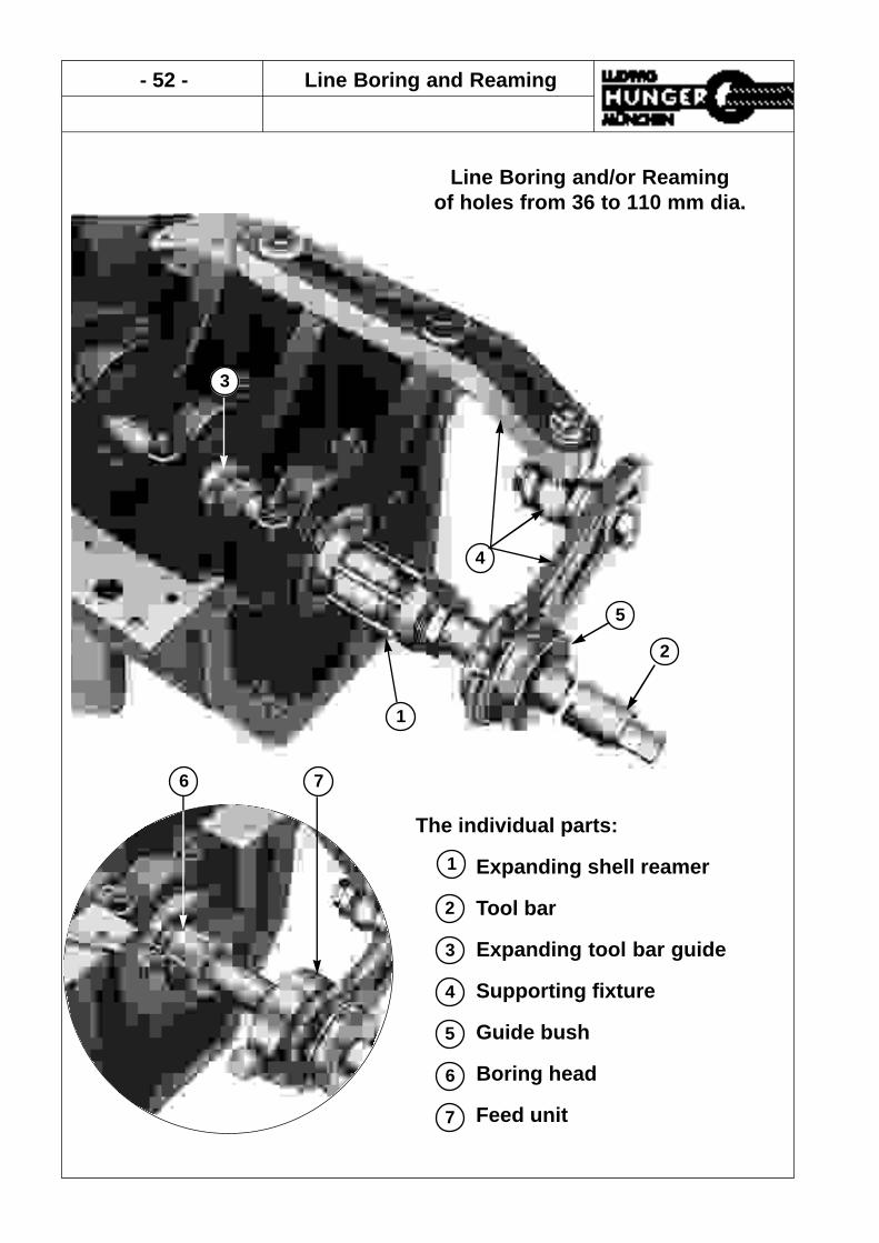
- 52 - Line Boring and Reaming
Line Boring and/or Reamingof holes from 36 to 110 mm dia.
The individual parts:
Expanding shell reamer
Tool bar
Expanding tool bar guide
Supporting fixture
Guide bush
Boring head
Feed unit
1
2
3
4
5
6
6 7
3
2
5
4
1
7

Line Boring and Reaming - 53 -
Expanding Reamers Type H
L2
SW
d
L1
Size Size Takes Length Length Nut No. of WeightRange Tool Bar Overall Blades SW Blades
mm d mm L1 mm L2 mm mm kg
H 36 36 - 38 20 96 44 32 6 0,370
H 38 38 - 41 20 99 44 34 6 0,450
H 41 41 - 44 20 104 48 38 6 0,590
H 44 44 - 47 25 104 48 40 6 0,590
H 47 47 - 51 25 108 48 43 6 0,760
H 51 51 - 54 30 108 52 47 5 0,830
H 54 54 - 58 30 113 52 47 6 0,930
H 58 58 - 62 30 113 52 53 6 1,180
H 62 62 - 65 35 114 52 58 8 1,290
H 65 65 - 69 35 118 57 58 8 1,490
H 69 69 - 73 40 118 57 64 8 1,790
H 73 73 - 78 40 123 57 68 8 1,990
H 78 78 - 83 45 124 57 70 8 2,110
H 83 83 - 88 45 124 60 78 8 2,750
H 88 88 - 93 50 124 60 83 8 3,000
H 93 93 - 99 50 127 60 83 10 3,490
H 99 99 - 105 50 127 60 * 10 4,200
H 105 105 - 111 50 127 60 * 10 5,040
Description:Right-hand cutting shell reamer with expanding blades.The reamer fits on a tool bar and may be positioned along the tool bar atany desired position.The reamer is automatically locked in place on the tool bar by an ex-pan-ding spring coupling as soon as the reamer blades are brought intoengagement with the bore.Expanding tool bar guides and supporting fixtures for the tool bar areavailable to ensure excact alignment of the tool bar when reaming aseries of aligned holes.The adjusting nut is marked with a circular scale. One graduation of thescale corresponds to an alteration of the reamer diameter by 0,02 mm.
Application:The reamer for inline reaming of a series of holes, particularly the holesof crankshaft and camshaft bearings.
* Adjustment of the nut with hook wrench.
Reamers type H with size range over 111 mm on application.

- 54 - Line Boring and Reaming
Tool Bars and Guides
Tool Bar Guidesfor Bore Expansion Range Weight
Part No. Reamer Size d mm mm kg
153 20 000 H 36 - H 41 20 35,5 - 54 0,200
153 25 000 H 44 - H 47 25 43,5 - 62 0,300
153 30 000 H 51 - H 58 30 49,5 - 74 0,410
153 35 000 H 62 - H 65 35 61,5 - 83 0,620
153 40 000 H 69 - H 73 40 68,5 - 93 0,800
153 45 000 H 78 - H 83 45 77,5 - 105 1,100
153 50 000 H 88 - H 105 50 87,5 - 127 1,550
Tool Barfor Diameter Length Square Weight
Part No. Reamer Size D mm L mm SW mm kg
152 20 101 H 36 - H 41 20 1000 13 2,420
152 25 101 H 44 - H 47 25 1000 13 3,740
152 30 121 H 51 - H 58 30 1200 16 6,540
152 30 151 H 51 - H 58 30 1500 16 12,000
152 35 121 H 62 - H 65 35 1200 18 8,750
152 40 151 H 69 - H 73 40 1500 18 14,400
152 45 151 H 78 - H 83 45 1500 22 18,110
152 50 171 H 88 - H 105 50 1700 22 25,200
Tool Bars for Shell Reamers Type H
Description:Precision ground bars with squares at both ends.Standard types are listed below.Special length guide bars on application.
Expanding Tool Bar Guides
Description:The tool bar guides are provided with wedges which can be forced outward against the hole to lock the tool bar guide in the hole.The wedges are actuated by an adjusting nut.
L
d
SW
D
Order Information:
Order Information:

Line Boring and Reaming - 55 -
Supporting Fixture
Supportin Fixture Individual Components of the Supporting FixtureSize Part No. Weight Mounting Base Clamping Arm Ball Joint
kg Size Part No. L1 mm Size Part No. L2 mm Part No.
IA 156 11 100 3,140 IA 156 11 110 330 IA 156 11 120 210 156 11 130IIA 156 12 100 5,100 IIA 156 12 110 400 IIA 156 12 120 270 156 11 130IIA1 156 12 102 5,100 IIA 156 12 110 400 IA 156 11 120 210 156 11 130
Guide Bushes for Clamping Arm Size IASize Part No. Bore Dia. Weight
for Bar kg
IA/20 156 21 200 20 mm 0,920IA/25 156 21 250 25 mm 0,880IA/30 156 21 300 30 mm 0,820IA/35 156 21 350 35 mm 0,750IA/40 156 21 400 40 mm 0,650IA/45 156 21 450 45 mm 0,600IA/50 156 21 500 50 mm 0,550
Guide Bushes for Clamping Arm Size IIASize Part No. Bore Dia. Weight
for Bar kg
IIA/40 156 22 400 40 mm 1,940IIA/45 156 22 450 45 mm 1,890IIA/50 156 22 500 50 mm 1,800
Supporting Fixture for Tool Bars
Description:The universal supporting fixture is designed to locate a tool bar guide bush in front of an endbearing hole for perfect alignment of the tool bar in centerline with the hole.The guide bush is locked in a clamping arm which is connected by a ball joint to a mountingbase which is attached to the cylinder block or cylinder head.Both the clamping arm and the ball joint are adjustable to ensure proper alignment.
Order Information:
L1
L2
Mounting Base
Tool Bar
Guide Bush
Ball Joint
Clamping Arm

- 56 - Line Boring and Reaming
Boring Heads & Feed Devices
Boring Dimensions Weighthead Diameter of hole Range of ad- kgPart for tool bar justing tool barNo. d mm D mm
154 30 000 30 50 - 58 0,340154 31 000 30 53 - 62 0,420154 35 000 35 61 - 69 0,520154 40 000 40 68 - 78 0,660154 45 000 45 77 - 88 0,870154 50 000 50 87 - 99 1,230154 52 000 50 92 - 105 1,440154 54 000 50 98 - 111 1,670
Feeddevice Diameter of hole Weight
Part for tool bar kgNo. mm
155 20 000 20 0,330155 25 000 25 0,360155 30 000 30 0,730155 35 000 35 0,760155 40 000 40 0,830155 45 000 45 0,840155 50 000 50 0,850
Boring HeadsDescription:Then.boring heads are designed to counterbore the holebefor finish reamingThe boring heads are fitted with an adjustable single pointcutting tool..A set screw is provided to adjust the cutting tool.
Feed DevicesDescription:The feed devices provide automated feed of the tool bar inaxial direction when the tool bar is rotated.The feed device must be located just behind the guidebush.A knurled screw is provided for engaging and disengagingthe automated feed.
D
d
Boring heads and tool bars for 20 & 25 mm on request.