catalog 550-7 vision air handler -...
TRANSCRIPT
Engineered for flexibility and performance™
Catalog 550-7Vision™Air HandlerSizes 003 to 090
MEA342-99-E

2 Daikin Catalog 550-7
Nomenclature and Certification . . . . . . . . . . . . . . . . . 3ARI Certification . . . . . . . . . . . . . . . . . . . . . . . . . . . . 3IBC Certification (optional) . . . . . . . . . . . . . . . . . . . . 3Agency Listed . . . . . . . . . . . . . . . . . . . . . . . . . . . . . . 3
The Vision Air Handler Advantage . . . . . . . . . . . . . . . 4Flexibility . . . . . . . . . . . . . . . . . . . . . . . . . . . . . . . . . . 4Indoor Air Quality . . . . . . . . . . . . . . . . . . . . . . . . . . . 4Operating Efficiency . . . . . . . . . . . . . . . . . . . . . . . . . 5Easy, Low Cost Installation . . . . . . . . . . . . . . . . . . . . 5Easy Maintenance and Serviceability . . . . . . . . . . . . 5
Introduction . . . . . . . . . . . . . . . . . . . . . . . . . . . . . . . . . 6Quality . . . . . . . . . . . . . . . . . . . . . . . . . . . . . . . . . . . . 6Flexibility . . . . . . . . . . . . . . . . . . . . . . . . . . . . . . . . . . 6Cabinet Construction . . . . . . . . . . . . . . . . . . . . . . . . . 6Access and Serviceability . . . . . . . . . . . . . . . . . . . . . 8Vision SelectTools™ Software Selection Program . . 9
Vision™ Unique Standard Features . . . . . . . . . . . . 10
Vision Customized Options . . . . . . . . . . . . . . . . . . . 12
Component Types . . . . . . . . . . . . . . . . . . . . . . . . . . . 14Fans . . . . . . . . . . . . . . . . . . . . . . . . . . . . . . . . . . . . 14Coils . . . . . . . . . . . . . . . . . . . . . . . . . . . . . . . . . . . . 16Filters . . . . . . . . . . . . . . . . . . . . . . . . . . . . . . . . . . . 16What is the MERV Rating? . . . . . . . . . . . . . . . . . . . 17Ultraviolet Light Options . . . . . . . . . . . . . . . . . . . . . 18Access . . . . . . . . . . . . . . . . . . . . . . . . . . . . . . . . . . . 18Mixing Boxes and Economizers . . . . . . . . . . . . . . . 18Face and Bypass Dampers . . . . . . . . . . . . . . . . . . . 18Blenders/Air Mixers . . . . . . . . . . . . . . . . . . . . . . . . . 19Attenuators . . . . . . . . . . . . . . . . . . . . . . . . . . . . . . . 19Digital Ready™ Air Handlers . . . . . . . . . . . . . . . . . 19Starters and VFDs . . . . . . . . . . . . . . . . . . . . . . . . . . 20Energy Recovery . . . . . . . . . . . . . . . . . . . . . . . . . . . 20Electric Heaters . . . . . . . . . . . . . . . . . . . . . . . . . . . . 22
Air Handler Selection . . . . . . . . . . . . . . . . . . . . . . . . 23Selecting Coils . . . . . . . . . . . . . . . . . . . . . . . . . . . . 23Selecting Accessories . . . . . . . . . . . . . . . . . . . . . . . 23Selecting Fans . . . . . . . . . . . . . . . . . . . . . . . . . . . . 23
Quick Select Table . . . . . . . . . . . . . . . . . . . . . . . . . . . 24
Application Considerations . . . . . . . . . . . . . . . . . . . 26Installation Flexibility . . . . . . . . . . . . . . . . . . . . . . . . 26Mounting and Access . . . . . . . . . . . . . . . . . . . . . . . 26Ductwork . . . . . . . . . . . . . . . . . . . . . . . . . . . . . . . . . 26Piping and Drain Pan Traps . . . . . . . . . . . . . . . . . . 27Vibration Isolation . . . . . . . . . . . . . . . . . . . . . . . . . . 27Multizone Air Handler Applications . . . . . . . . . . . . . 27Sound . . . . . . . . . . . . . . . . . . . . . . . . . . . . . . . . . . . 27Air Supply Systems and Fan Laws . . . . . . . . . . . . . 27Fan and Motor Heat . . . . . . . . . . . . . . . . . . . . . . . . 28Variable Air Volume . . . . . . . . . . . . . . . . . . . . . . . . 29Variable Frequency Drives . . . . . . . . . . . . . . . . . . . 29
Engineering and Physical Data . . . . . . . . . . . . . . . . 30Component and Section Weights . . . . . . . . . . . . . 42Fan Data . . . . . . . . . . . . . . . . . . . . . . . . . . . . . . . . 44Coil Data . . . . . . . . . . . . . . . . . . . . . . . . . . . . . . . . 48Multizone Coils . . . . . . . . . . . . . . . . . . . . . . . . . . . . 51Side Load Filter Data . . . . . . . . . . . . . . . . . . . . . . . 52
Dimensional Data . . . . . . . . . . . . . . . . . . . . . . . . . . . 54Top Horizontal Housed Fan Discharge . . . . . . . . . 54Bottom Horizontal Housed Fan Discharge . . . . . . . 56Upblast Housed Fan Discharge . . . . . . . . . . . . . . . 58Downblast Housed Fan Discharge . . . . . . . . . . . . 60Belt Drive Plenum Fan Discharge . . . . . . . . . . . . . 62Fan Array . . . . . . . . . . . . . . . . . . . . . . . . . . . . . . . . 63Direct Drive Plenum Fan Discharge . . . . . . . . . . . . 64Dual Direct Drive Plenum Fan Discharge . . . . . . . 65Inline Fan Discharge . . . . . . . . . . . . . . . . . . . . . . . 66Cooling Coil Section . . . . . . . . . . . . . . . . . . . . . . . . 67Combination Cooling and Reheat Coil Section . . . 68Heating Coil Section . . . . . . . . . . . . . . . . . . . . . . . 69Horizontal Discharge Two-Deck Multizone Coil Section . . . . . . . . . . . . . . . . . . . . . . . . . . . . . . 70Vertical Discharge Two-Deck MultizoneCoil Section . . . . . . . . . . . . . . . . . . . . . . . . . . . . . . 71Horizontal Discharge Three-Deck MultizoneCoil Section . . . . . . . . . . . . . . . . . . . . . . . . . . . . . . 72Vertical Discharge Three-Deck MultizoneCoil Section . . . . . . . . . . . . . . . . . . . . . . . . . . . . . . 73Side Load Flat and Angular Filter Section . . . . . . . 74Side Load Cartridge and Bag Filter Section . . . . . . 75Front Load Cartridge and Bag Filter Section . . . . . 76Mixing Box and Combination Filter Mixing Box . . . 77Economizer Section . . . . . . . . . . . . . . . . . . . . . . . . 78Blenders . . . . . . . . . . . . . . . . . . . . . . . . . . . . . . . . . 79Access Doors . . . . . . . . . . . . . . . . . . . . . . . . . . . . . 80Diffuser . . . . . . . . . . . . . . . . . . . . . . . . . . . . . . . . . . 81Access Section . . . . . . . . . . . . . . . . . . . . . . . . . . . 82Internal/External Face and Bypass Sections . . . . . 83Discharge or Return Plenum . . . . . . . . . . . . . . . . . 84Sound Attenuator Section . . . . . . . . . . . . . . . . . . . 85Base Rail . . . . . . . . . . . . . . . . . . . . . . . . . . . . . . . . 86
Electrical Data . . . . . . . . . . . . . . . . . . . . . . . . . . . . . . 87Supply Power Wiring . . . . . . . . . . . . . . . . . . . . . . . 87
Engineering Guide Specification . . . . . . . . . . . . . . 88PART 1: GENERAL . . . . . . . . . . . . . . . . . . . . . . . . 88PART 2: PRODUCTS . . . . . . . . . . . . . . . . . . . . . . 89PART 3: EXECUTION . . . . . . . . . . . . . . . . . . . . . . 98
Nomenclature and Certification
Nomenclature and Certification
Figure 1: Nomenclature
ARI Certification
Certified in accordance with the forced circulation air cooling and air heating coils certification program, which is based on ARI Standard 410.
Standard and custom size units certified in accordance with the central station air handling units certification program, which is based on ARI Standard 430.
Note–Ratings at other than wide open position of the inlet vanes are outside the scope of ARI Standard 430.
IBC Certification (optional)
Seismic certification per applicable buildings codes tested and analyzed in accordance with:
Available upon request.
Agency Listed
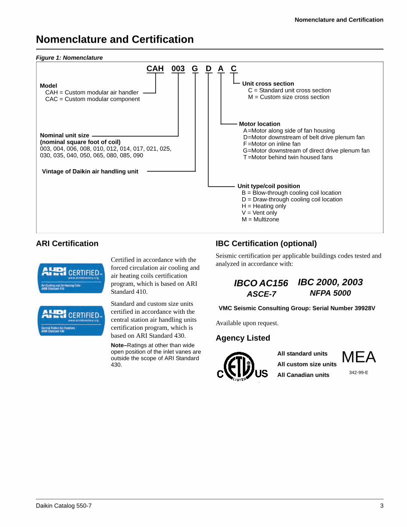
CAH 003 G D A C
ModelCAH = Custom modular air handlerCAC = Custom modular component
Nominal unit size (nominal square foot of coil)003, 004, 006, 008, 010, 012, 014, 017, 021, 025,030, 035, 040, 050, 065, 080, 085, 090
Vintage of Daikin air handling unit
Unit cross sectionC = Standard unit cross sectionM = Custom size cross section
Motor locationA=Motor along side of fan housingD=Motor downstream of belt drive plenum fanF =Motor on inline fanG=Motor downstream of direct drive plenum fanT =Motor behind twin housed fans
Unit type/coil positionB = Blow-through cooling coil locationD = Draw-through cooling coil locationH = Heating onlyV = Vent onlyM = Multizone
IBCO AC156 ASCE-7
IBC 2000, 2003NFPA 5000
VMC Seismic Consulting Group: Serial Number 39928V
All standard units
All custom size units
All Canadian units
MEA342-99-E
Daikin Catalog 550-7 3

The Vision Air Handler Advantage
The Vision Air Handler Advantage
FlexibilityVision unique design What it can do for you
Custom-modular platformAllows customizing of the system with a wide selection of components and sizes.
Variable DimensioningTM design Allows cabinet to be sized in two-inch increments (height and width) to meet installation or aesthetic requirements.
Ships assembled or by sectionMinimizes install time; reduces installation cost; and allows passage through doors, tight spaces, and in elevators (great for retrofit jobs).
Multiple coil, fan and filter selectionsAllows optimum selections for cost, energy efficiency, performance, indoor air quality, and low noise.
Wide selection of base rail heights (4" to 12")Allows for condensate trapping, eliminates need for costly housekeeping pad, and provides space required between condensate connection and traps on steam applications.
Painted cabinet Enhances exterior appearance for units in visible locations.
Indoor Air QualityVision unique design What it can do for you
Low-leakage cabinet construction
Standard Cabinet: less than 0.5 CFM/ft2 of cabinetry at -6" to +5" positive w.c.
Vision Plus Cabinet: less than Class 6 leakage up to + / - 8" w.c.
Minimizes air leakage, noise and unfiltered air.
Double sloped microbial-resistant coated galvanized (standard) or stainless steel drain pan
Inhibits bacterial growth; eliminates standing water that can support bacteria.
Double-wall, foam injected construction Eliminates fiberglass fibers eroding into the air stream.
Multiple filter types (flat, angular, bag and cartridge) with side-load and front-load capabilities
Gives full range of filter efficiencies, final filter arrangements, and filter section depth flexibility.
Hinged access doors with full-grip handlesAllows for easy inspection and cleaning of drain pans; promotes regular inspections.
Patented splice collarPrevents unfiltered, unconditioned air from entering the system. Allows for leak-resistant section to section joining in the field.
Easy-to-remove access panelsAllows for easy inspection and cleaning of drain pans; promotes regular inspections.
4 Daikin Catalog 550-7

The Vision Air Handler Advantage
Operating EfficiencyVision unique design What it can do for you
The Vision Plus low air-leakage cabinet design, all inside and outside panel penetrations are sealed
Increases operating efficiency; reduces energy loss and operating costs.
Patented gasketed frame channelsMinimizes direct exposure of metal to metal in cabinet framework to reduce cold bridging and condensate collection; lowers operating costs.
Energy recovery (plate heat exchanger or energy recovery wheel)
Reduces cost of heating or cooling outside air; recovers up to 50% of the energy normally exhausted from a building.
Fan selection options (housed forward curve or airfoil, belt drive or direct drive plenum, inline and twin fans)
Results in lowest possible BHP requirements.
Patented UltraSealTM low-leak dampers Maximizes operating efficiency; reduces operating cost.
Double wall liners with injected foam insulationR-13 insulation value reduces condensation and improves operating efficiency.
Easy, Low Cost Installation
Vision unique design What it can do for you
Ships assembled or by sectionMinimizes install time, reduces installation cost; allows passage through doors, tight spaces and in elevators (ideal for retrofit jobs).
Complete disassemblyAllows for complete knock down during installation if required for tight fitapplications.
Patented section splicing Saves installation time; creates an airtight environment.
Extended coil connections with gasketed airseal, external drains and vents
Eliminates need to remove panels for connection during installation; preserves air-tight environment; saves time and cost.
Bolted frame construction with removable panels
Provides complete accessibility to unit components.
Fan system factory tested and balanced Saves time during installation and promotes proper operation.
Discharge or inlet plenum sectionsAdapts easily to ductwork and provides a turning section for stacked components.
Easy Maintenance and ServiceabilityVision unique design What it can do for you
Direct-drive plenum fans No fan bearings, belts or drives to replace or maintain
Removable cross-member frame channels
Allows for top or side coil removal without disrupting unit integrity.
Extended fan bearing lube lines Makes lubricating fan system easier.
Extended coil drain connections Reduces coil venting time; helps coil condensate drain completely.
Hinged access doors with full-grip handles Allows for proper inspection.
Daikin Catalog 550-7 5
Introduction
Introduction
Quality
Daikin air handling equipment has been respected and regarded as high quality for nearly 60 years. Daikin has taken a major step in redefining the indoor air handler with the Vision air handler. Demands for improved indoor air quality, low sound, high operating efficiency and smaller mechanical rooms require a better product for today’s air handler market. The Daikin Vision air handler is designed to meet or exceed these demands.
The key to providing such a high quality product is in the basic design. The Daikin Vision air handler's patented construction provides unequaled thermal efficiencies and low leak rates. In addition, Vision air handlers offer tremendous flexibility in sizing, component options, and unit arrangements to meet the indoor air quality, operating efficiency, sound and installation requirements for today’s extensive commercial and custom markets.
Flexibility
By virtue of its unique frame design, the Daikin Vision air handler offers tremendous flexibility. This flexibility is reflected in our unique Variable Dimensioning™ feature that allows units to be sized in two-inch increments (height and width) to fit the available space. Numerous section and component options, and the ability to arrange components in whatever arrangement is required, allow Vision air handlers to be customized to the requirements of each job, without expensive field modifications. Finally, Vision air handlers can be shipped as a completely assembled unit, in modules or by component sections for new or retrofit applications that require smaller sections for passage through the building.
Cabinet Construction
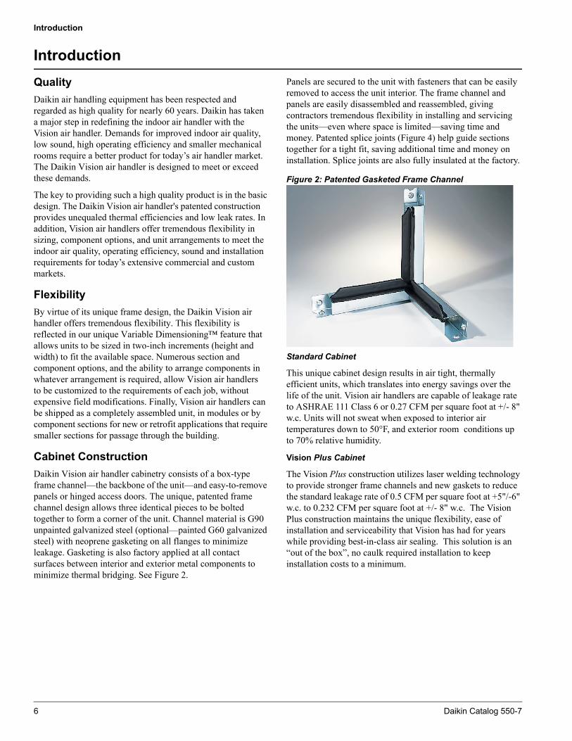
Daikin Vision air handler cabinetry consists of a box-type frame channel—the backbone of the unit—and easy-to-remove panels or hinged access doors. The unique, patented frame channel design allows three identical pieces to be bolted together to form a corner of the unit. Channel material is G90 unpainted galvanized steel (optional—painted G60 galvanized steel) with neoprene gasketing on all flanges to minimize leakage. Gasketing is also factory applied at all contact surfaces between interior and exterior metal components to minimize thermal bridging. See Figure 2.
Panels are secured to the unit with fasteners that can be easily removed to access the unit interior. The frame channel and panels are easily disassembled and reassembled, giving contractors tremendous flexibility in installing and servicing the units—even where space is limited—saving time and money. Patented splice joints (Figure 4) help guide sections together for a tight fit, saving additional time and money on installation. Splice joints are also fully insulated at the factory.
Figure 2: Patented Gasketed Frame Channel
Standard Cabinet
This unique cabinet design results in air tight, thermally efficient units, which translates into energy savings over the life of the unit. Vision air handlers are capable of leakage rate to ASHRAE 111 Class 6 or 0.27 CFM per square foot at +/- 8" w.c. Units will not sweat when exposed to interior air temperatures down to 50°F, and exterior room conditions up to 70% relative humidity.
Vision Plus Cabinet
The Vision Plus construction utilizes laser welding technology to provide stronger frame channels and new gaskets to reduce the standard leakage rate of 0.5 CFM per square foot at +5"/-6" w.c. to 0.232 CFM per square foot at +/- 8" w.c. The Vision Plus construction maintains the unique flexibility, ease of installation and serviceability that Vision has had for years while providing best-in-class air sealing. This solution is an “out of the box”, no caulk required installation to keep installation costs to a minimum.
6 Daikin Catalog 550-7
Introduction
ASHRAE 111 is the test standard to test duct leakage. The standard uses a class system to indicate relative leakage rates. These class levels are dependent on static pressure and surface area. The formula for leak class is:
Using this standard will give the most accurate rating for how the unit selected will perform.
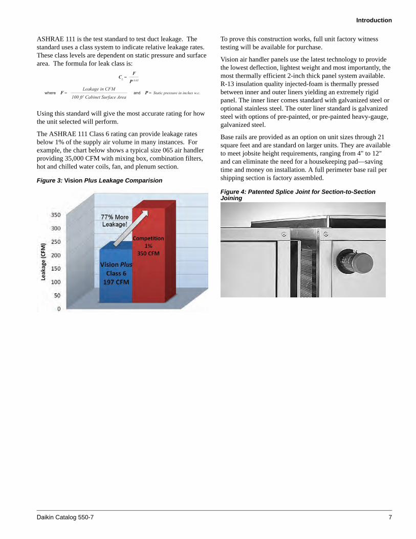
The ASHRAE 111 Class 6 rating can provide leakage rates below 1% of the supply air volume in many instances. For example, the chart below shows a typical size 065 air handler providing 35,000 CFM with mixing box, combination filters, hot and chilled water coils, fan, and plenum section.
Figure 3: Vision Plus Leakage Comparision
To prove this construction works, full unit factory witness testing will be available for purchase.
Vision air handler panels use the latest technology to provide the lowest deflection, lightest weight and most importantly, the most thermally efficient 2-inch thick panel system available. R-13 insulation quality injected-foam is thermally pressed between inner and outer liners yielding an extremely rigid panel. The inner liner comes standard with galvanized steel or optional stainless steel. The outer liner standard is galvanized steel with options of pre-painted, or pre-painted heavy-gauge, galvanized steel.
Base rails are provided as an option on unit sizes through 21 square feet and are standard on larger units. They are available to meet jobsite height requirements, ranging from 4" to 12" and can eliminate the need for a housekeeping pad—saving time and money on installation. A full perimeter base rail per shipping section is factory assembled.
Figure 4: Patented Splice Joint for Section-to-Section Joining
and P = Static pressure in inches w.c.where F = Leakage in CFM
100 ft2 Cabinet Surface Area
CL = F
P 0.65
Daikin Catalog 550-7 7

Introduction
Seismic Design Considerations
Strict design, testing, and certification requirements for heating, ventilating, and air-conditioning equipment are clearly defined in the International Building Code, versions 2000 and 2003, for designated structures in earthquake-prone locations. The goals of these requirements are to maintain systems to protect the public from hazard and maintain essential public services immediately after an earthquake. With the widespread adoption of the IBC throughout the U.S., it is important to understand its requirements and their impact on your specific building, and where you can turn for equipment to satisfy those requirements. Tested and certified compliant with the seismic provisions of the IBC, Daikin Vision and Skyline air handlers also comply with the construction requirements of NFPA 5000.
For use by the building official and design professional, the IBC has defined Seismic Use Group designations based on building use along with specific criteria for determining the Seismic Design Category of the building and the applicability of seismic design criteria to the building’s mechanical equipment. Provide this information to your local Daikin Sales Representative so the proper modifications can be made to the air handler and have a compliance label affixed to the product so all IBC requirements in this regard are complied with. For additional information, Daikin has several published articles explaining in detail IBC seismic requirements. Go to www.DaikinApplied.com or contact your local Daikin Sales Representative to obtain these articles.
Figure 5: Top and Side Panel, Frame Channel Removal for Component Replacement
Access and Serviceability
Equipment must be designed to perform efficiently and withstand the wear and tear of everyday use. It must be designed to provide easy access to interior components for routine maintenance and service to maintain peak performance. The patented frame channels and easy-to-remove panels or hinged access doors of the Vision air handler cabinet provide complete access to the unit interior and components. Components, including the fan and coil assembly, can be removed through the side of the unit, top of the unit, or a combination of both, which reduces required service clearances (Figures 6 and 5). Coil removal on unstacked coils does not require access to the non-connection end of the coil. A unique coil tie down method simplifies coil removal and replacement.
Figure 6: Easy Access for Maintenance and Service
8 Daikin Catalog 550-7

Introduction
Vision SelectTools™ SoftwareSelection Program
Because the Daikin Vision air handler is so flexible and has so many different component types, there virtually are an infinite number of possible unit arrangements. To help the customer easily define their product requirements, Daikin provides a user-friendly software selection program, called Vision SelectTools. This program configures and sizes both standard and custom units. Components can be selected in minutes. This Windows® based program leads the user through the selection process by prompting for pertinent input data for all components required. Component sections are
selected by placing them on a configuration screen. Once the unit layout is defined, the options and accessories are identified. The program gives immediate feedback regarding fan and coil selection, offering a choice of many different options based on the performance inputs. Once final component selections have been made, the program provides all output needed for specification and submittal purposes, including fan curves, coil performance psychometric charts, weights, dimensional drawings, and a unit specification.A fully detailed.DXF file is also available. Vision SelectTools is a comprehensive, efficient and user-friendly software selection program
Daikin Catalog 550-7 9

Vision™ Unique Standard Features
Vision™ Unique Standard Features
Gasketed Frame Channel
• Eliminates metal-to-metal contact between paneling and framework
• Minimizes cabinet condensateand corrosion
• Facilitates top and sidecomponent removal
• Promotes long life
Patented UltraSeal™ Low-Leak Dampers
• Help maximize operating efficiency
• Reduces operating cost
Extended Coil Connections
• Reduces installation costs
• Reduces maintenance time
• Aids proper drainage
• Grommet seal reduces leakage
Rugged Cabinet Enclosure
• Rigid, thermal efficient (R-13)injected-foam panels are strong and lightweight
• Promotes longer unit life Smooth Interior Surface
• Reduces dirt accumulation
• Facilitates cleaning
• Helps improve IAQ
10 Daikin Catalog 550-7

Vision™ Unique Standard Features
VisDr
• Mc
• H
Frame Channel Disassembly
• Allows two-sided access.
• Easier, faster service and maintenance
Patented Splice Collar
• Reduces installation cost
• Creates an airtight environment
ible Double-Sloped ain Pan
akes inspection andleaning easier
elps improves IAQ
Variable Height Base Rails (4" to 12")
• Eliminates costly housekeeping pad
• Allows for condensate trapping
Custom-Modular design
• Allows custom selection andconfiguration of components
• Allows design of system tomeet space and performance requirements
Daikin Catalog 550-7 11
Vision Customized Options
Vision Customized Options
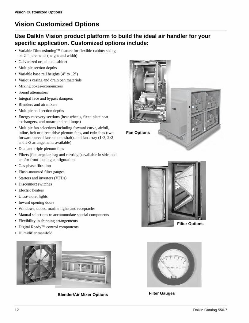
Use Daikin Vision product platform to build the ideal air handler for your specific application. Customized options include:• Variable Dimensioning™ feature for flexible cabinet sizing
on 2" increments (height and width)
• Galvanized or painted cabinet
• Multiple section depths
• Variable base rail heights (4" to 12")
• Various casing and drain pan materials
• Mixing boxes/economizers
• Sound attenuators
• Integral face and bypass dampers
• Blenders and air mixers
• Multiple coil section depths
• Energy recovery sections (heat wheels, fixed plate heatexchangers, and runaround coil loops)
• Multiple fan selections including forward curve, airfoil,inline, belt or direct drive plenum fans, and twin fans (twoforward curved fans on one shaft), and fan array (1×3, 2×2and 2×3 arrangements available)
• Dual and triple plenum fans
• Filters (flat, angular, bag and cartridge) available in side loadand/or front-loading configuration
• Gas-phase filtration
• Flush-mounted filter gauges
• Starters and inverters (VFDs)
• Disconnect switches
• Electric heaters
• Ultra-violet lights
• Inward opening doors
• Windows, doors, marine lights and receptacles
• Manual selections to accommodate special components
• Flexibility in shipping arrangements
• Digital Ready™ control components
• Humidifier manifold
Blender/Air Mixer Options
Fan Options
Filter Options
Filter Gauges
12 Daikin Catalog 550-7

Vision Customized Options
Energy Recovery Equipment Sound Attenuators Marine Lights and Accessories
Daikin Catalog 550-7 13

Component Types
Component Types
Fans
Fan types available with the Daikin Vision air handling units are housed double width, double inlet (DWDI) forward curved and airfoil fans, plenum fans, inline fans, twin fans and fan array. Forward curved fans generally provide the lowest first cost option and are used for lower static pressure applications.
DWDI Housed Fans
Daikin housed forward curved fans will typically operate up to 6.0" of static pressure. Airfoil fans have a higher first cost, but are more efficient, quieter and can handle higher static pressures. Daikin housed airfoil fans will operate up to 9.0" of static pressure.
Plenum Fans
Plenum fans (Figure 7) save space by eliminating turns in ductwork. They also provide a high degree of flexibility when locating the outlet ductwork. Plenum fans are also very good for blow-through applications as they generate a uniform outlet velocity profile. Both belt drive and direct drive plenum fans are available.
Direct drive plenum fans offer easier maintenance as they do not have fan bearings, sheaves, or belts.
Dual Fans
Direct drive plenum fans come with the optional dual arrangement. The multi-fan sets will provide more even air flow and redundancy if one fan should need servicing.
For redundancy, the rule of thumb is that one fan will provide approximately 65% of the total CFM provided by both fans if the remaining fan is not sped up. If more redundancy is required, then a VFD and larger motor can be used to speed up the single fan to achieve more airflow. The selection software will calculate the redundancy. If a manual calculation is required to calculate the maximum available airflow from the single fan, manually plot the single fan performance onto the dual fan curve as in Figure 8. Extend the single fan rpm line to intersect with the system static pressure line. This balance point shows the performance of a single fan when one fails.
Figure 7: Plenum Fan
If a VFD is used, the fan can be sped up to the limit of the HP of the motor to get more airflow. To increase redundancy, a larger motor can be selected. Remember that over sized fan motors may be less efficient. This typically occurs below 50- 60% design bhp. If you over size the motor to increase redundancy, as the motor BHP drops farther away from the actual HP, the motor will run less and less efficiently. So, if the application is meant for dual fans, it may be best to simply use the best selection for efficiency and utilize what redundancy comes with this selection. This will ensure the customer will have the most efficient operating setup while having the insurance of good redundancy.
The width of the fans will determine which cabinets will allow certain fans. Table 1 will help by showing what minimum cabinet width and unit size you will need for specific fan diameter selections.
An optional motor removal gantry system is available for the Dual Plenum Fan and Fan Array options. The gantry option provides easier serviceability of motors if access is not available on both sides of the fan section.
Table 1: Dual Fan Width Requirements
Direct Drive Plenum Fan
Size
Miniumum Width (in.)
Minumum Standard Unit Size
11 64 010
12 64 010
15 68 014*
16 72 014*
18 80 017
20 88 030*
22 92 030*
24 100 035*
27 108 040
30 116 040
33 124 065
36 136 065
40 152 107 T
44 164 107 T
T Extended Cabinet*Not on 4" width
14 Daikin Catalog 550-7

Component Types
Figure 8: Dual Fan Redundancy – 65% if one fan fails
Fan Array
The fan array section will decrease the fan section length by using multiple smaller direct drive fans. With the stacked array, the fans will also provide a more even airflow pattern throughout the unit and will allow the fans to be placed closer to the coil. In addition, the multiple fans provide redundancy. If one fan needs to be serviced, there can be up to five other fans to back it up. All fans in the fan array are direct drive and offer more efficient performance with no belt losses and no required shaft bearing maintenance.
An optional motor removal gantry system is available for the Fan Array option. The gantry option provides easier serviceability of motors if access is not available on both sides of the fan section.
Inline fans are quieter and more efficient than most standard fans. Inline fans are most beneficial in VAV applications.
Twin fans (two housed forward curved fans mounted on one common shaft) are excellent in both retrofit units and stacked energy recovery units. Twin fans can handle high cfm in very low profile units.
The different types of fans are available in numerous wheel diameters per unit size. The fan size selection is always optimized and identified by the SelectTools software. The program considers performance, efficiency, sound generation and first cost and offers a number of fan sizes to select from. Fan and motor assemblies can be provided with 2" spring (Figure 9), rubber in shear, or rigid mount allowing the customer the option of isolating the fan and motor assembly
internally or isolating the entire unit. All fans are dynamically balanced at the plant as an assembly, including the motors and drives.All belt drive fans rotate on a solid steel shaft of uniform diameter that has been ground, polished, and coated with a rust inhibitor. Fan shafts are selected to have a maximum operating speed well below the first critical speed.
Belt guards are available on plenum fans and inline fans. Seismic restraint is also available for seismic active locations.
The fan bearings have a minimum L50 life of 200,000 hours, and are available as high as one million hours. Bearings are selected for minimum noise levels and minimal service. Bearings are self aligning and pre-lubricated for immediate use. Bearings are mounted on rigid frames and positioned to provide proper balance. All bearings include copper lubrication lines that are extended to the access side of the fan cabinet with the grease fittings located near the access door opening.
Daikin Catalog 550-7 15

Component Types
All fan motors are internally mounted. The appropriate motor size will be selected by the SelectTools software. Motors cannot be undersized, but may be oversized if desired. Motor options include open drip proof, totally enclosed fan cooled, 1 speed/1 winding, 2 speed/1 winding, and 2 speed/2 winding. Motor efficiencies available include standard efficiency, high efficiency, and premium efficiency, depending on the motor type.
Figure 9: Spring Isolation
Coils
The Daikin Vision air handler offers broad application flexibility in coil sections and coils. Coils can be arranged in draw-through, blow-through, and multizone configurations. Heating only, cooling only, or cooling and heating sections are available. All coils are installed with space between each coil to allow access for cleaning and mounting of controls.
Cooling coil sections, and cooling and heating coil sections, are available in seven different section lengths to accommodate every application requirement. Drain pans extend the full length of the section. Removable access panels or doors may be provided in the deeper sections that will not interfere with piping connections extending through the unit side panels.
All cooling coils are mounted over a double sloped drain pan. The cooling coil rests on coil supports located over the drain pan. The drain pan extends beyond the leaving side of the coil to help recover condensate. The primary drain pan also extends under the coil headers and return bends to help remove condensate from the unit. A full thickness of insulation is always provided between the drain pan and the bottom outer panel. The drain pan is sloped in two planes to promote proper condensate removal. The galvanized drain pan is coated with an antimicrobial treatment as standard to further inhibit the growth of algae and fungi. A stainless steel drain pan is also available as an option.
Coil connections are grommet sealed inside and outside to ensure low cabinet leakage, and the connections always extend through the unit cabinetry, allowing for the easy connection of
valves and piping (Figure 10). Water coil vents and drains are located outside the cabinetry.
Coils are available in a range of face area sizes, including small, medium, medium extended, large, extended and staggered. Generally, small face area coils are used for heating applications, large face area coils are used for cooling applications with bypass, and extended face area coils are used to maximize the unit cross section for restricted space applications. The extended coil is used to maintain coil face velocity limitations to avoid going to a larger cabinet size, saving valuable floor space and money.
With Daikin being a major manufacturer of heat transfer coils, the coil options are virtually unlimited. The Daikin contractor coil line has several coil types, ranging from hot and cold water, refrigerant and steam. Standard Daikin coils are ARI certified. In addition to a broad range of circuitings, fin spacing and row depths, coils can be constructed of different material types for fins, tubes, connections, and casings. This provides the ability to specify a coil to meet the application requirements.
For more information on Daikin coils, consult the following catalogs:
Cooling—water/refrigerant.................................... Catalog 411
Heating—water/booster......................................... Catalog 412
Steam—standard / distributing ............................. Catalog 413
Figure 10: Coil Connections, Vents, Drains, and Drain Pan Connection, Extend Through Unit Cabinetry
Filters
The Daikin Vision air handler is designed to house flat, angular, bag, or cartridge filters. These media types range in efficiencies up to 95% and MERV 15. (See page 18 for a description of the MERV Rating.) In addition to offering a full range of efficiencies, the filter media can be provided with an optional antimicrobial treatment. Antimicrobial treatments are highly recommended for a complete filtration system.An optional filter pressure gauge may be ordered with each filter section to help promote regular servicing and prevent clogging.
Both bag and cartridge filters have a pre-filter and can be either side load or front load. An access door is provided on either side or both sides of the unit to access the filter section. Filters
16 Daikin Catalog 550-7

Component Types
can be positioned any place in the unit, and as many filter sections as required can be used. Many health and food industries require stringent filtration. Often, a filter section must be the last component in the air stream.
The Daikin Vision air handler meets these requirements by providing a filter section located as the last component in the air stream, and with full sheet metal liners.
Figure 11: Filter Particle Size Chart (in microns)
Figure 12: Pollutant Particle Size Chart (in microns)
What is the MERV Rating?
Minimum Efficiency Reporting Value (MERV)—ASHRAE Standard 52.2-1999 entitled “Method of Testing General Ventilation Air-Cleaning Devices for Removal by Particle Size” provides a methodology for determining filter efficiency at removing various sizes of particles (see Figure 12) as the filters become loaded. There are three ranges of particle sizes that define the MERV value:
Range 1—0.3 to 1.0 m particle size.
Range 2—1.0 to 3.0 m particle size.
Range 3—3.0 to 10.0 m particle size.
1 10 100 1000 100000.10.01
0.3 3 30
1
2
3
4
1 Filters of average efficiency2 Filters of high efficiency3 Filters of very high efficiency4 Activated carbon
filters
1 10 100 1000 100000.10.01
0.3 3 30
1 2 3 4 5
6 7
8 9
10
11 12
151413
16 17 18
212019
22
1 Smog2 Haze3 Mist4 Drizzle5 Rain6 Oil fire smoke7 Fly-ashes8 Tobacco smoke9 Ashes10 Metallic dust11 Soot12 Cement dust13 Gas molecules14 Pigments15 Pollen16 Suspended dust17 Precipitating dust18 Heavy industrial dust19 Viruses20 Bacteria21 Hair22 Lung damaging dust
Daikin Catalog 550-7 17

Component Types
The table below shows a comparison of the MERV rating to the average arrestance percentage by the older ASHRAE Standard 52.1 method:
Standard Filter Types Available:
• MERV 5 – 2" depth. Flat panel filter designed for heavy dustloading conditions.
• MERV 7 – 2" or 4" depth. Pleated.
• MERV 8 – 2" or 4" depth. Pleated filter with two layers ofadded polypropylene laminate to increase efficiency.
• MERV 15, 14, and 11 – 4" depth, 1" track requirement. Minipleated filters with metal cell sides and headers that providesuperior moisture resistance.
• MERV 15, 14, and 11 – 12" depth, 1" track requirement.Steel interlocked header and cell sides hold the corrugatedaluminum separated pleats allowing optimum airflow. RatedUL Class 1.
• MERV 15, 14, and 11 – 12" depth, 1" track requirement.Mini pleats held in a V-bank configuration providing greaterairflow capacity and longer service.
• MERV 15, 14 and 11 – 36", 30" and 22" depths, 1" trackrequirement. Extended surface pockets made from high-loft,layered synthetic media. Rated UL Class 1 MERV 8efficiency filters also available in 19", 15" and 12" depths.
Ultraviolet Light Options
Vision air handlers can be factory equipped with ultraviolet (UV) light options that are pre-engineered for placement to provide maximum effectiveness. Two UV light options are available. The first can be mounted on the downstream side of all cooling coils and above the unit drain pan for surface “kill” applications to comply with the GSA Facilities Standard for federal buildings. The second can be mounted in the air stream prior to filter(s) for “kill on the fly” applications. Both applications are agency approved to UL Category Code ABQK specification, HVAC Accessories, Air Duct Mounted, in addition to the ETL listing of Vision air handlers.
Access
Access sections can be selected to meet specific application criteria. They can be placed anywhere in a unit in a variety of depths and are available in depths of 16", 24", 30", 36", 42", 48", and 54". Typically, access sections are used for field-
installed components, air monitoring devices, or to provide ample space between components.
Mixing Boxes and Economizers
When outside and return air mixing is required, either a mixing box or an economizer section can be selected. Either component will regulate the amount of outside and return air supplied to the conditioned space. The mixing box or economizer can make use of free cooling by opening outside air dampers when the ambient air will help to condition the supply air stream. Additionally, dampers may be individually sized to provide better mixing.
Both the mixing box and economizer are provided with a Daikin UltraSeal™ low leak damper. This damper has one of the lowest leakage rates in the industry, maximizing energy efficiency. At 4.0" static pressure and a face velocity of 1100 fpm through the dampers, the leakage rate is less than 0.2% (it is common to specify leakage rates at higher static pressures, but dampers should not exceed 2" of static pressure). The parallel airfoil blades are hollow core and fully gasketed. Continuous vinyl seals are provided between the damper blades. Stainless steel end seals and linkage built into high strength ABS plastic endcaps provide smooth, quiet operation.
Face and Bypass Dampers
Face and bypass dampers can be provided to modulate temperature by bypassing air around the coil. The opposed blades meter varying air volumes through the coil and bypass to attain the final air temperature demanded. Daikin Vision air handlers offer only low leak dampers in their face and bypass sections.
Three styles of face and bypass sections are available.
• Internal bypass is available for use with medium face areacoils (Figure 13).
Figure 13: Internal Face and Bypass Dampers
• External bypass and external right angle are used whenlarger face area coils are required. The damper blades arefabricated of continuous galvanized steel with the damperrods rotating in nylon bushings. Damper shaft extensions aresupplied to facilitate damper motor location.
Table 2: MERV Rating vs. AHSHRAE Standard 52.1
Standard 52.2 (MERV)
Approx. standard 52.1 Particle size rangeDust spot efficiency Arrestance
15 >95% n/a 1
14 90 to 95% >98% 1
11 60 to 65% >95% 2
8 30 to 35% >90% 3
6 <20% 85 to 90% 3
18 Daikin Catalog 550-7

Component Types
• Integral face and bypass. Vision air handlers arepre-engineered to provide an accurate, reliable method ofpreheating and tempering air in standard or make-up airapplications. Integral face and bypass coils maintainconstant steam pressure or tube velocities through the coil tohelp prevent freeze-ups, while varying airflow through thecoil using bypass dampers. The amount of air bypassed orheated is determined by a preset leaving air temperature. Itcan vary from the bypass dampers being fully closed (all airpasses through the coil) for maximum heat output, to thebypass dampers being fully open (no air passes through thecoil) for minimum heat output. The air is then mixed at thedischarge of the coil to achieve the desired leaving airtemperature. Air pressure drop is maintained constantregardless of the position of the dampers.
Blenders/Air Mixers
Stratification can occur from the mixing box when airflow from two different temperature air streams do not mix completely. This incomplete mixing can continue through the air handler and subject an unprotected coil (no glycol) to freezing temperatures, damaging the coil. With the increased minimum outdoor air requirements as identified by ASHRAE Standard 62, the likelihood for air stratification increases. An air handler must be able to handle the required amount of outdoor air, regardless of temperature, without risking damage to the coil.
Blenders/air mixers help to provide protection for coils against freeze-up due to stratification. They add additional turbulence to the passing air streams, boosting the air velocity for improved mixing. Proper distance is provided immediately downstream to give the air streams enough time to fully mix before reaching the next air handler component. Because blenders/air mixers are static devices, they require no maintenance. Different blender/air mixer lengths can be selected to satisfy either the acoustic, space, pressure drop, or initial cost requirements. The Vision SelectTools software can help select the appropriate blender/air mixer for the application.
Figure 14: Blender
Attenuators
Building occupants have become increasingly conscious of the quality of their environments, and low sound levels are a key criteria. Studies have confirmed improved productivity when workers are performing in sound-controlled environments. Consequently, building owners, engineers, and architects are designing their projects with stringent sound criteria to maximize this economic benefit.
Daikin Vision air handlers are designed to provide quiet sound levels. Factory-installed attenuators are available for the discharge or return sections of the air handling unit to meet the most stringent sound attenuation requirements. Different attenuator lengths can be selected to satisfy either the acoustic, space, pressure drop, or initial cost requirements. Quality construction and an aerodynamic design give reliable performance, low pressure drop and low initial cost. The Vision SelectTools Software can help choose the correct attenuator for your application.
Figure 15: Attenuator Section
Digital Ready™ Air Handlers
Vision Air Handlers can be factory-equipped with industry standard direct digital control (DDC) components for easy, low cost integration with controls by others. Sensors and actuators are selected for maximum compatibility with most DDC control systems, and are neatly wired within their shipping section to a conveniently located junction box. Digital Ready Vision air handlers save the time and costly labor needed to identify, purchase and field install DDC components to match your control system. You also benefit from uniform, proper positioning of DDC components at our factory, which promotes reliable start-up and operation.
Daikin Catalog 550-7 19

Component Types
Starters and VFDs
A variety of factory-installed motor control options are available to provide operation and maintenance protection, motor efficiency, and flexibility for the Vision air handler. These options include: Disconnect Switch, Starters, Combination Starter/Disconnect, Variable Frequency Drive (VFD) with Disconnect Switch, and VFD with Disconnect Switch and Bypass. Line reactors are available on both VFD with Disconnect Switch and VFD with Disconnect Switch and Bypass.
A unit mounted disconnect switch provides the means for disconnecting power in sight from the motor when required by the National Electric Code (NEC). The switch is a heavy-duty type with a non-fused disconnect switch in a NEMA 1 enclosure. A fused disconnect is also available.
Factory mounted starters offer remote start/stop operation and overload protection for an individual fan motor with minimum field cost to wire line and control circuit power to the unit. All starters provided are NEMA rated. Additional options include auxiliary contacts, control transformer, selector switch, push buttons, and pilot lights. A combination starter is a starter packaged with a safety switch. These motor controllers provide remote start/stop operation as well as disconnecting means in sight of the controller.
A VFD provides adjustable speed control of a single fan motor. Factory mounted outside the fan cabinet, the VFD provides not only a lower cost than field installation, but also an optimal installation location. VFDs are preprogrammed and include a keypad for local or remote control.
A unit installed VFD with disconnect provides local or remote speed control for a single fan motor with disconnecting means within sight when required by the NEC. A non-fused disconnect is offered packaged with the VFD in a separate NEMA 1 enclosure. Installation is limited to the connection of power and control wires at the device.
Packaged VFD with disconnect and bypass offers added motor control at the unit for critical fan applications. With bypass control, power to the VFD can be switched to allow full operation of the fan motor in case of VFD failure. VFDs with disconnect switch, bypass and line reactors provide harmonic control when needed.
Energy Recovery
Maintaining acceptable indoor air quality is generally accomplished by introducing ventilation from outdoors. The air must be conditioned to match the indoor space requirements. Heat wheels and fixed plate heat exchangers are available as factory-installed options for Vision air handlers. These energy recovery components can recover 50% or more of the energy normally exhausted from a building. These devices capture heat from exhaust air as it passes through the air handler and transfer it to the supply air stream, reducing the cost of heating or cooling the outside air. Energy recovery components do this by transferring energy from a warm air
stream to a colder air stream—heating cold outside air during the winter and cooling hot air during the summer.
The fixed plate creates a cross flow as it collects heat and conducts it to the other side of the plate. The fixed plate has no moving parts, is easy to clean, has a low pressure drop, can be sealed against cross contamination, and is offered in a wide range of configurations.
The heat recovery wheel rotates at low speeds, capturing and transferring both sensible (heat) energy and latent (moisture) energy. The ability to transfer both sensible and latent energy gives the heat wheel several advantages. First, the required capacity of ventilation equipment is significantly reduced. Additionally, the heat wheel works at lower temperatures without frosting. The supply air from the heat wheel is not near saturation, and moisture in the ductwork is not an issue. Further, no condensate pan or drain is required. Finally, heat wheels provide humidification so that the humidifier can be downsized. They also help to keep humidity in spaces where humidification is not applied, providing greater comfort to these zones.Both types of energy recovery devices are configured on the inlets and outlets with splice collars to match the adjacent sections. The fixed plate requires two drip pans, which can be either microbial resistant galvanized steel or stainless steel.
The side-by-side arrangement will often fit an energy recovery unit into spaces with height restrictions relative to the standard stacked arrangement. For example, if the application requires 9,000 CFM and bypass dampers, the stacked arrangement would require 108" in total height while the side-by-side would only need 72", but will require an added 62" in width. This arrangement will also allow easy access to both supply and return air streams since both are on the same level.
Since the diameter of the energy recovery wheel will often be the limiting factor of the unit height, the selection of the side-by-side arrangement will almost always require custom cabinet dimensions. Below shows what minimum cabinet height will be required for specific airflow ranges to get good energy recovery wheel selections.
Both types of energy recovery devices are configured on the inlets and outlets with splice collars to match the adjacent sections. The fixed plate requires two drip pans, which can be either microbial resistant galvanized steel or stainless steel.
20 Daikin Catalog 550-7

Component Types
Table 3: Daikin Stacked Energy Wheel Cabinet Limitations Guide
AiRotorWithout Bypass Dampers With Bypass Dampers
Maximum Airflow(CFM)
Minimum Width (inches)
Minimum Height Single Cabinet (inches)
Maximum Height Single Cabinet (inches)
Minimum Height Single Cabinet (inches)3
Maximum Height Single Cabinet (inches)
1,296 40 26 92 30 92
2,060 46 26 92 34 92
3,357 52 26 92 38 92
5,193 62 30 92 44 92
7,974 72 34 92 52 92
9,737 78 38 88 56 88
12,366 86 42 84 60 84
16,091 98 48 78 68 78
20,312 108 52 74 74 74
25,019 118 58 68 N/A N/A
30,222 128 62 N/A N/A N/A
NovelAireWithout Bypass Dampers With Bypass Dampers
Maximum Airflow(CFM)
Minimum Width (inches)
Minimum Height Single Cabinet (inches)
Maximum Height Single Cabinet (inches)
Minimum Height Single Cabinet (inches)3
Maximum Height Single Cabinet (inches)
817 32 26 92 26 92
1,177 38 26 92 30 92
2,092 48 26 92 34 92
2,647 50 26 92 36 92
3,607 56 26 92 38 92
4,710 62 30 92 44 92
5,966 62 30 92 44 92
5,962 68 32 92 46 92
7,552 68 32 92 50 92
7,357 74 36 90 54 90
9,319 74 36 90 54 90
8,902 80 38 88 56 88
11,276 80 38 88 56 88
10,597 86 42 84 62 84
13,423 86 42 84 62 84
12,434 92 44 82 62 82
15,750 92 44 82 66 82
14,422 98 48 78 64 78
18,268 98 48 78 72 78
20,975 104 50 76 74 76
23,864 110 54 72 N/A N/A
26,942 116 56 70 N/A N/A
30,200 124 60 62 N/A N/A
Note – 1. All heights are “per airstream”2. Assumes 6" bases3. Dampers Sized for listed maximum airflow
Daikin Catalog 550-7 21

Component Types
Electric Heaters
Electric heaters extend the versatility of the Vision air handler. With negligible air pressure drop, accurate controllability, light weight, easy serviceability and inherent freeze protection, electric heaters are valuable alternatives to conventional steam and hot water heating coils.
ETL-approved electric heaters are available on all standard sizes (003-090) for horizontally-mounted draw through units in both left and right hand configurations. All units are open wire style construction, with automatic and manual backup limit controls, air switch, stainless steel terminals, power on pilot light, magnetic contactors and integral control boxes. Safety interlock switches, step controllers and vernier silicon controlled rectifiers (SCRs) are available options.
The heater requires its own electric service. Heaters are available in 208V, 240V, 480V and 600V (all 3 phase) and use
an internal 24-volt control circuit. Standard kW ranges are available for each heater size and are designed to give an approximate temperature rise from 20°F to 60°F, depending on the airflow through the unit. Typical pressure drops range from .01 to .04 inches of water, depending on the air velocity and number of rows of heating elements.
An integral control box with optional door handle power disconnect is included with the electric heater. Insulated panels are factory installed behind the control box. Any standard motor may be used, although the discharge air from the electric heater must not exceed 104°F since the rated ambient temperature of the motor will be exceeded. The heater is assembled into a separate section of the Vision air handler. Standard section widths include 30", 34", 42", and 46" and vary depending on unit size, control type and kW used.
Table 4: Daikin Side-by-Side Energy Wheel Cabinet Limitations GuideAiRotor
Without Bypass Dampers With Bypass DampersMaximum
Airflow(CFM)Minimum
Width (inches)Minimum Height
Single Cabinet (inches)Maximum Height
Single Cabinet (inches)Minimum Height
Single Cabinet (inches)2Maximum Height
Single Cabinet (inches)1,296 36 30 228 34 2282,060 42 32 228 36 2283,357 48 36 228 42 2286,138 60 37 228 52 2288,540 68 41 228 56 2289,737 74 48 228 58 22813,076 84 49 228 66 22816,100 94 58 228 72 22820,321 104 64 228 80 22825,037 114 58 228 86 228
NovelAireWithout Bypass Dampers With Bypass Dampers
Maximum Airflow(CFM)
Minimum Width (inches)
Minimum Height Single Cabinet (inches)
Maximum Height Single Cabinet (inches)
Minimum Height Single Cabinet (inches)2
Maximum Height Single Cabinet (inches)
817 28 26 228 30 2281177 32 28 228 32 2282092 44 34 228 38 2282647 48 36 228 40 2283607 54 38 228 44 2284710 60 42 228 48 2285966 60 42 228 52 2285962 66 44 228 54 2287552 66 44 228 54 2287357 72 48 228 58 2289319 72 48 228 58 2288902 78 50 228 60 22811276 78 50 228 62 22810597 84 52 228 62 22813423 84 54 228 66 22812435 90 56 228 66 22815750 90 56 228 70 22814422 96 60 228 72 22818268 96 60 228 76 22820976 102 62 228 78 22823864 108 66 228 84 22826942 114 68 228 86 22830200 122 72 228 92 228
Note – 1. All heights are “per airstream”2. Assumes 6" bases
22 Daikin Catalog 550-7

Air Handler Selection
Air Handler Selection
Selecting flexible Vision air handlers depends on many different criteria. The Quick Select tables on pages 24 and 25 provide a rough determination of air handler needs. To simplify this process, Daikin designed an innovative computerized selection program—Vision SelectTools software. It allows the user to develop an air handler from the ground up and obtain all of the detail required for proper design and specification. The user can design a unit in a matter of minutes.
The program is completely integrated. All input data is carried through the selection process and considered as calculations are made. Because the program is integrated, the opportunity for errors is reduced. The software guides the user through the selection process. On-line editing helps select only viable options. The program is provided so that even the less experienced user can select air handlers accurately.
Designing an efficient air handler system depends on accurate system design and proper equipment selection. Factors that affect unit selection include applicable codes, ventilation requirements, heating and cooling space loads, acceptable temperature differentials, and thermal media and installation limitations. Unit selection can be broken down into four steps: unit type and size, coils, accessories, and fan and motor requirements.
Generally, the unit is selected based on the air volume required and the desired face velocity through the cooling coil. For cooling coils, 400 to 600 feet per minute is considered the optimum face velocity range for dehumidification and the prevention of any moisture carryover. The Vision SelectTools software recommends the unit size based on air flow and face velocity requirements. Once the unit size is determined, select the coils and all accessory components. Once all components and coils are selected (identifying the total internal component pressure drop), select the fan.
Selecting CoilsThe Vision air handler provides the ability to select from multiple face area coils per unit size. Once the coil size is selected, the row and fin requirements can be determined based on performance criteria. Daikin offers an extensive line of coil types and circuitings. This wide variety of circuiting, row, and fin spacing, in addition to different material types, can provide a coil selection that handles the load required.
Heating, cooling, and combination cooling and reheat sections are available. Coil sections come in many different depths to accommodate multiple rows of coils, and to provide access on the leaving air side or between coils for cleaning and inspection of the drain pan. Access in the coil section can be minimized or maximized depending on the space available and job needs. Coil sections can be placed as needed in the unit, and as many sections as required for conditioning of air can be provided.
Selecting AccessoriesA complete selection of component and section types in a variety of unit arrangements and configurations is available for air mixing, filtration, and temperature control to meet specific application requirements. The outside and/or return air can be brought into the unit through a plenum, mixing box, or economizer. For mixing of the two air streams, dampers are required to modulate and direct outside and return air, which is accomplished using a mixing box or economizer. Both section types use the Daikin patented UltraSeal™ low leak dampers. Blenders/air mixers also are available to provide proper mixing of two air streams, to prevent stratification and to help avoid damage to equipment due to freezing temperatures.
To promote good air filtration, many different filter media types and arrangements are offered. Filters can be provided in angular or flat filter racks, a variety of media efficiencies, and with or without a prefilter. The filter section can be located anywhere in the unit to filter air as it enters the unit, or in a final filter arrangement before it leaves the unit. Bag or cartridge filters can be either front or side loading.
Also available are many different size access sections for field-installed components or to provide access between components. Other options include diffusers, plenums, face and bypass dampers, sound attenuators, and blenders/air mixers. Standard access doors open outward for maximum accessibility to internal components.
On pressurized sections, most doors open inward to help maintain the extremely low cabinet leakage rate of the Vision unit and to prevent doors from being inadvertently opened when the cabinet is under pressure.
Selecting Fans Fan selection requires an accurate calculation of the resistance to the airflow through the entire system. This total resistance consists of the sum of two parts—the external and internal static pressure. The external static pressure is the static pressure found in the distribution system, external to the air handler. The internal unit resistance is the sum of the resistance of the coils and various other unit components and accessories. Component pressure drops are listed for specific air flows in this catalog. Use the Vision SelectTools software to determine internal component pressure drops of the system. Once the total static pressure is known, the software identifies the fans available to properly handle the air flow and static pressure for the system. The software generates a full fan curve based on the fan selection and point of operation.
WARNINGSMOKE CONTROL AND MANAGEMENT SYSTEMSImproper smoke or fume air handling can result in severe personal injury or death. A registered professional engineer must design and approve the air conditioner and air handler application to make sure smoke and fume control meet local fire codes and NFPA requirements for the specific building application.
Daikin Catalog 550-7 23
Quick Select Table
Quick Select Table
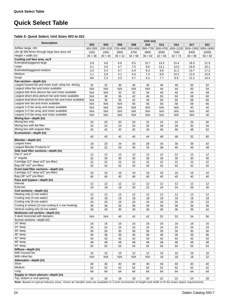
Table 5: Quick Select, Unit Sizes 003 to 021
Description Unit size
003 004 006 008 010 012 014 017 021Airflow range, cfm 900–2500 1200–3100 1700–4600 2200–6000 2900–7700 3600–9700 4200–11200 5000–13500 6000–16000cfm @ 500 ft/min through large face area coil 1550 1950 2850 3750 4800 6050 7000 8400 10050Height × width (in) 26 × 38 30 × 40 30 × 52 34 × 58 36 × 64 42 × 66 42 × 74 46 × 80 58 × 82Cooling coil face area, sq ftExtended/staggered large 3.9 4.8 6.6 8.5 10.7 13.5 15.4 18.3 21.9Large 3.1 3.9 5.7 7.5 9.6 12.1 14.0 16.8 20.1Extended/staggered medium 2.6 3.4 4.7 6.4 8.3 9.8 11.2 13.7 17.2Medium 2.1 2.8 4.1 5.6 7.4 8.8 10.2 12.6 15.8Small NA 2.3 3.3 4.7 6.4 7.7 8.9 11.2 14.4Fan section—depth (in)Largest housed fan and motor avail. w/top hor. dischg. 32 32 36 40 40 46 46 50 52Largest inline fan and motor available N/A N/A N/A N/A N/A 44 44 50 54Largest belt drive plenum fan and motor available N/A N/A 32 32 34 40 40 44 48Largest direct drive plenum fan and motor available N/A 36 36 42 46 50 50 58 60Largest dual direct drive plenum fan and motor available N/A 36 36 42 46 50 50 58 60Largest twin fan and motor available N/A N/A N/A 50 56 56 58 58 66Largest 1×3 fan array and motor available N/A N/A N/A N/A N/A N/A N/A 40 40Largest 2×2 fan array and motor available N/A N/A N/A N/A N/A N/A N/A N/A 40Largest 2×3 fan array and motor available N/A N/A N/A N/A N/A N/A N/A N/A 40Mixing box—depth (in)Mixing box only 20 20 20 20 22 24 24 26 30Mixing box with flat filter 24 24 24 24 26 28 28 30 34Mixing box with angular filter 42 42 42 42 44 46 46 48 52Economizer—depth (in)
40 40 40 40 44 48 48 52 60Blender—depth (in)Largest Kees 18 20 24 26 28 34 36 38 42Largest Blender Products IV 18 22 26 30 34 38 40 46 48Side load filter sections—depth (in)Flat 2" and 4" 12 12 12 12 12 12 12 12 122" angular 32 30 30 30 30 30 30 30 30 Cartridge (12" deep w/2" pre-filter) 22 22 22 22 22 22 22 22 22 Bag (36" w/2" pre-filter) 42 42 42 42 42 42 42 42 42 Front load filter sections—depth (in)Cartridge (12" deep w/2" pre-filter) 16 16 16 16 16 16 16 16 16Bag (36" w/2" pre-filter) 40 40 40 40 40 40 40 40 40Face and bypass—depth (in)Internal 12 12 12 12 12 12 12 12 12External 18 18 18 20 22 24 24 26 30Coil sections—depth (in)Heating only (2-row water) 12 12 12 12 12 12 12 12 12Cooling only (4-row water) 18 18 18 18 18 18 18 18 18Cooling only (6-row water) 24 24 24 24 24 24 24 24 24Cooling & reheat (12-row cooling & 1-row heating) 36 36 36 36 36 36 36 36 36Vertical cooling only (6-row water) 30 30 30 30 36 36 36 36 42Multizone coil section—depth (in)3 deck horizontal with dampers N/A N/A 40 42 42 52 52 54 56Access sections—depth (in)16" deep 16 16 16 16 16 16 16 16 1624" deep 24 24 24 24 24 24 24 24 2430" deep 30 30 30 30 30 30 30 30 3036" deep 36 36 36 36 36 36 36 36 3642" deep 42 42 42 42 42 42 42 42 4248" deep 48 48 48 48 48 48 48 48 4854" deep 54 54 54 54 54 54 54 54 54Diffuse—depth (in)With housed fan 10 10 10 12 12 16 16 16 16With inline fan N/A N/A N/A N/A N/A 18 18 18 22Attenuator—depth (in)Short 40 40 40 40 40 40 40 40 40Medium 52 52 52 52 52 52 52 52 52Long 64 64 64 64 64 64 64 64 64Supply or return plenum—depth (in)Top, bottom or end opening 14 16 16 18 20 22 22 24 28Note: Based on typical industry sizes, Vision air handler units are available in 2-inch increments of height and width to fit the exact space requirements.
24 Daikin Catalog 550-7

Quick Select Table
Table 6: Quick Select Table, Sizes 025 to 090
Description Unit size
025 030 035 040 050 065 080 085 090Airflow range, cfm 7300–
194008500–22500
10000–26500
11500–31000
15000–40000
20000–54000
21500–57500
23100–61600
24600–65600
cfm @ 500 feet/minute through large face area coil 12150 14150 16700 19300 24500 33300 35900 38450 41000Height × width, in 60 × 86 60 × 98 66 × 102 68 × 116 80 × 120 92 × 136 98 × 136 104 × 136 110 × 136Cooling coil face area, sq ftExtended/staggered large 27.4 31.9 37.1 42.9 58.0 76.9 82.0 87.1 92.2Large 24.3 28.3 33.4 38.6 49.0 66.6 71.8 76.9 82.0Extended/staggered medium 21.3 24.8 29.7 34.3 40.1 61.5 61.5 66.6 71.8Medium 18.2 21.2 24.1 30.0 35.7 51.2 51.2 56.4 61.5Small 16.7 19.5 22.3 27.9 31.2 46.1 46.1 51.2 56.4Fan section—depth, inLargest housed fan and motor avail. w/top hor. dischg. 58 58 58 70 80 92 92 92 92Largest inline fan and motor available 64 64 70 70 90 96 96 96 96Largest belt drive plenum fan and motor available 50 54 54 52 60 68 68 68 68Largest direct drive plenum fan and motor available 66 66 66 74 78 78 78 78 78Largest dual direct drive plenum fan and motor available 66 66 66 74 78 78 78 78 78Largest twin fan and motor available 66 74 82 82 82 N/A N/A N/A N/ALargest 1×3 fan array and motor available 40 40 46 52 52 52 52 52 52Largest 2×2 fan array and motor available 40 40 46 52 52 58 62 64 64Largest 2×3 fan array and motor available 40 40 46 52 52 52 52 52 52Mixing box—depth, inMixing box only 32 32 36 36 40 46 50 54 56Mixing box with flat filter 36 36 40 40 44 50 54 58 60Mixing box with angular filter 54 54 58 58 62 68 72 76 78Economizer—depth, in
64 64 72 72 80 92 100 108 112Blender—depth, inLargest Kees 46 48 58 58 68 76 80 84 84Largest Blender Products IV 52 60 64 70 74 88 88 92 92Side load filter sections—depth, inFlat 2" and 4" 12 12 12 12 12 12 12 12 122" angular 32 32 32 32 32 32 32 32 32Cartridge (12" deep w/2" pre-filter) 22 22 22 22 22 22 22 22 22Bag (36" w/2" pre-filter) 42 42 42 42 42 42 42 42 42Front load filter sections—depth, inCartridge (12" deep w/2" pre-filter) 16 16 16 16 16 16 16 16 16Bag (36" w/2" pre-filter) 40 40 40 40 40 40 40 40 40Face and bypass—depth, inInternal 12 12 12 12 12 12 12 12 12External 32 32 34 38 44 50 54 56 58Coil sections—depth, inHeating only (2-row water) 12 12 12 12 12 12 12 12 12Cooling only (4-row water) 18 18 18 18 18 18 18 18 18Cooling only (6-row water) 24 24 24 24 24 24 24 24 24Cooling & reheat (12-row cooling & 1-row heating) 36 36 36 36 36 36 36 36 36Vertical cooling only (6-row water) 48 48 54 N/A N/A N/A N/A N/A N/AMultizone coil section—depth, in3 deck horizontal with dampers 60 60 70 70 76 88 N/A N/A N/AAccess sections—depth, in16" deep 16 16 16 16 16 16 16 16 1624" deep 24 24 24 24 24 24 24 24 2430" deep 30 30 30 30 30 30 30 30 3036" deep 36 36 36 36 36 36 36 36 3642" deep 42 42 42 42 42 42 42 42 4248" deep 48 48 48 48 48 48 48 48 4854" deep 54 54 54 54 54 54 54 54 54Diffuser—depth, inWith housed fan 24 24 24 30 30 30 30 30 30With inline fan 26 26 28 30 36 38 38 38 38Attenuator—depth, inShort 40 40 40 40 40 40 40 40 40Medium 52 52 52 52 52 52 52 52 52Long 64 64 64 64 64 64 64 64 64Supply or return plenum—depth, inTop, bottom or end opening 30 30 32 32 38 42 48 52 54Note: Based on typical industry sizes, Vision air handler units are available in 2-inch increments of height and width to fit the exact space requirements.
Daikin Catalog 550-7 25
Application Considerations
Application Considerations
Installation Flexibility
Daikin central station Vision air handlers feature sectionalized design and can ship fully assembled or in sections as required by the job site condition to provide maximum installation flexibility. Multiple fan, coil, filter, mixing box, face and bypass, and access components allow the design flexibility of built-up systems with the cost advantage of factory fabricated units. Units can be shipped from the factory in as few or as many sections as required according to job site condition.
Mounting and Access
Whether units are floor or ceiling mounted, take care to keep the supporting structure level and rigid enough for satisfactory unit operation. Ideally, a heavy concrete slab should be used for floor mounted units and main support beams should be used for ceiling supported units. Ceiling suspended units must be trapeezed from the unit base rail or field-supplied materials. Avoid long floor or ceiling spans.
Locate units so there is proper access for routine service. Clearance for filter removal on both sides of the filter section is usually necessary. Provide clearance as required for access panels. Allow room for coil removal. Cooling units require clearance for a trap in the drain pan line.
Access to the interior of the Vision air handler is provided by hinged access doors or removable panels. For access between components, versatile access sections feature hinged access doors on either or both sides.
Ductwork
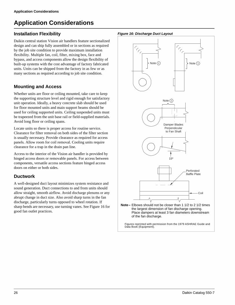
A well-designed duct layout minimizes system resistance and sound generation. Duct connections to and from units should allow straight, smooth airflow. Avoid discharge plenums or any abrupt change in duct size. Also avoid sharp turns in the fan discharge, particularly turns opposed to wheel rotation. If sharp bends are necessary, use turning vanes. See Figure 16 for good fan outlet practices.
Figure 16: Discharge Duct Layout
Coil
PerforatedBaffle Plate
Damper BladesPerpendicularto Fan Shaft
15º
Note 1 Note 1
Note 2
Note– Elbows should not be closer than 1 1/2 to 2 1/2 times the largest dimension of fan discharge opening.Place dampers at least 3 fan diameters downstream of the fan discharge.
Figures reprinted with permission from the 1979 ASHRAE Guide and Data Book (Equipment).
26 Daikin Catalog 550-7

Application Considerations
Piping and Drain Pan Traps
Design and install piping in accordance with accepted industry standards. Do not apply undue stress at the connection to coil headers. Support pipe work independently of the coils with adequate piping flexibility for thermal expansion. Run drain lines and traps full size from the drain pan connection. Drain pans must have traps to allow the condensate from the coils to drain freely. On a draw-through unit, the trap depth and the distance between the trap outlet and drain pan outlet should be twice the negative static pressure under normal unit operation. See Figure 17.
Figure 17: Drain Pan Traps
Vibration Isolation
To help keep noise and vibration compatible with the intended use of the conditioned air space, apply good acoustical and vibration engineering practices during the early stages of design.
Since most applications require vibration isolation, the Vision air handler is available with factory-installed internal isolation. Internally isolated units feature spring or rubber in shear isolators sized specifically for each fan wheel and unit size.
Multizone Air Handler Applications
Blow-through air handlers are available in singlezone, two-deck, and three-deck configurations. The two-deck and three-deck units are offered with or without zone dampers. All unit configurations include a perforated plate fan discharge diffuser to provide even airflow downstream of the fan.
Multizone and dual duct air handlers typically provide comfort conditioning by distributing a constant air volume at variable temperature. In a typical system, a portion of the air is heated by passing through the heating coil; the balance is cooled by the cooling coil. The heated and cooled airstreams are then mixed in the required proportion to provide the optimum temperature air to the conditioned space.
For dual duct applications, a pair of ducts bring heated and cooled air to the air mixing terminal boxes where the airstreams are mixed. By adding zone dampers to the dual duct unit, the air mixing takes place at the unit discharge and only one duct is required to distribute conditioned air to the building. The air mixing terminal boxes also are eliminated.
By adding a third bypass deck to the hot and cold decks, a triple deck multizone is created. The triple deck configuration offers significant energy conservation opportunities by allowing return or outside air to bypass both coils. The thermal inefficiency of mixing heated and cooled air is eliminated by the addition of the bypass deck. Bypass air is mixed with heated air for building zones that require heating. Bypass air is mixed with cooled air for building zones that require cooling.
Multizone air handling systems result in an absence of water, steam and condensate drain piping, wiring, electrical and mechanical equipment in the conditioned space for more usable commercial floor area and higher rental income.
Sound
The unit inlet, outlet, and radiated sound levels for each octave band are calculated by the Vision SelectTools software, based on your specific application. Sound performance data is derived from testing performed in accordance with AMCA Standard 300. The effects of various components, casework, and unit configurations are taken into account.
Air Supply Systems and Fan Laws
An air supply system consists of an air handler cabinet, heat exchanger, filters, ductwork, grilles and registers used to distribute air throughout the building. The system is independent of the fan used to supply the system.
The resistance of the system, referred to as static pressure (SP), is dependent upon the quantity of air (cfm) that is moved through it. The air quantity is determined by the cooling, heating, and ventilating requirements.
For any system, the static pressure varies directly as the square of the air quantity. This relationship between cfm and SP establishes the system curve for that system and is expressed as follows:
The system curve is unique for a particular system configuration. Any change to the system caused by dirty filters, damper changes, etc., results in a new system curve.
For fans operating at low pressures (less than 10" W.G.), the effects of air compression are negligible. Disregarding air compression allows fan operation in a fixed system to be expressed by simple relationships. These relationships are known as fan laws and can be used to calculate the effects of fan speed and air density changes on this system.
Drain pan
2 P
2 P
Negativepressure (P)
cfm1
cfm2=
SP1
SP2SP2or = SP1
cfm2
cfm1)()( 2 2
Daikin Catalog 550-7 27
Application Considerations
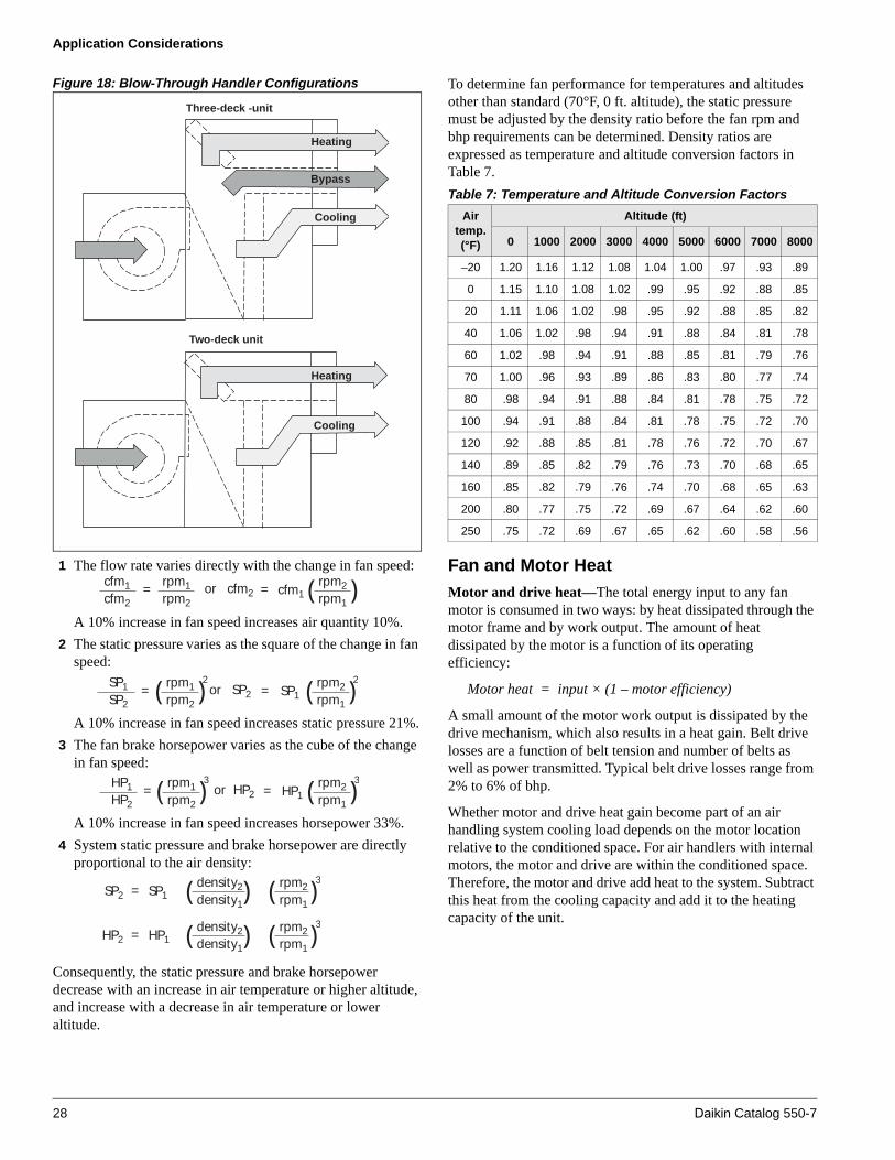
Figure 18: Blow-Through Handler Configurations
1 The flow rate varies directly with the change in fan speed:
A 10% increase in fan speed increases air quantity 10%.
2 The static pressure varies as the square of the change in fan speed:
A 10% increase in fan speed increases static pressure 21%.
3 The fan brake horsepower varies as the cube of the change in fan speed:
A 10% increase in fan speed increases horsepower 33%.
4 System static pressure and brake horsepower are directly proportional to the air density:
Consequently, the static pressure and brake horsepower decrease with an increase in air temperature or higher altitude, and increase with a decrease in air temperature or lower altitude.
To determine fan performance for temperatures and altitudes other than standard (70°F, 0 ft. altitude), the static pressure must be adjusted by the density ratio before the fan rpm and bhp requirements can be determined. Density ratios are expressed as temperature and altitude conversion factors in Table 7.
Fan and Motor Heat
Motor and drive heat—The total energy input to any fan motor is consumed in two ways: by heat dissipated through the motor frame and by work output. The amount of heat dissipated by the motor is a function of its operating efficiency:
Motor heat = input × (1 – motor efficiency)
A small amount of the motor work output is dissipated by the drive mechanism, which also results in a heat gain. Belt drive losses are a function of belt tension and number of belts as well as power transmitted. Typical belt drive losses range from 2% to 6% of bhp.
Whether motor and drive heat gain become part of an air handling system cooling load depends on the motor location relative to the conditioned space. For air handlers with internal motors, the motor and drive are within the conditioned space. Therefore, the motor and drive add heat to the system. Subtract this heat from the cooling capacity and add it to the heating capacity of the unit.
Three-deck -unit
Heating
Bypass
Cooling
Two-deck unit
Heating
Cooling
cfm1
cfm2=
rpm1
rpm2cfm2or = cfm1
rpm2
rpm1)(
SP1
SP2=
rpm1
rpm2SP2or = SP1
rpm2
rpm1)( 2)( 2
HP1
HP2=
rpm1
rpm2HP2or = HP1
rpm2
rpm1)( 3)( 3
=density2
density1HP2 HP1 )( rpm2
rpm1)( 3
=density2
density1SP2 SP1 )( rpm2
rpm1)( 3
Table 7: Temperature and Altitude Conversion Factors
Air temp. (°F)
Altitude (ft)
0 1000 2000 3000 4000 5000 6000 7000 8000
–20 1.20 1.16 1.12 1.08 1.04 1.00 .97 .93 .89
0 1.15 1.10 1.08 1.02 .99 .95 .92 .88 .85
20 1.11 1.06 1.02 .98 .95 .92 .88 .85 .82
40 1.06 1.02 .98 .94 .91 .88 .84 .81 .78
60 1.02 .98 .94 .91 .88 .85 .81 .79 .76
70 1.00 .96 .93 .89 .86 .83 .80 .77 .74
80 .98 .94 .91 .88 .84 .81 .78 .75 .72
100 .94 .91 .88 .84 .81 .78 .75 .72 .70
120 .92 .88 .85 .81 .78 .76 .72 .70 .67
140 .89 .85 .82 .79 .76 .73 .70 .68 .65
160 .85 .82 .79 .76 .74 .70 .68 .65 .63
200 .80 .77 .75 .72 .69 .67 .64 .62 .60
250 .75 .72 .69 .67 .65 .62 .60 .58 .56
28 Daikin Catalog 550-7

Application Considerations
Fan heat generation—All of the power input to a fan results in heat gain, which must be considered as a cooling load. The amount of heat generated is directly proportional to the fan bhp:
Fan heat (Btuh) = bhp × 2545
Much of this heat generation occurs within the fan itself. Fans are not 100% efficient, and the energy losses that occur convert directly into heat. The work done by the fan on the airstream increases the temperature, pressure, and velocity of air. The heat of compression required to raise the airstream to this increased energy level is also a heat gain.
As the air travels throughout the building, its energy is deteriorated by friction, resulting in pressure drop. This is also heat gain, but it does not result in temperature rise because the air expands as the pressure is reduced. The expansion is a cooling process that offsets the heat generated by friction.
Typical fan and motor heat values are given in Figure 19.
Figure 19: Fan and Motor Heat Gain
Variable Air Volume
Daikin variable air volume systems (VAV) employ the concept of varying the air quantity to a space at a constant temperature thereby balancing the heat gains or losses and maintaining the desired room temperature. This true variable volume system is commonly referred to as a “squeeze-off” or “pinch-off” system. Unlike a “bypass” or “dump” system, supply air is diverted from areas where it is not required to areas that need cooling and, at system part load conditions, reduces the total fan volume. This ability to reduce supply air quantities not only provides substantial fan energy savings at partial load conditions, but it also minimizes equipment sizing.
Variable volume systems offer the following advantages:
• Lowers system first cost by using system diversity to reduceequipment and duct sizes.
• Lowers operating costs by reducing fan energy demands,especially at part load conditions.
• Lowers first cost by reducing space requirements for ducttrunks and mechanical equipment.
• Provides system flexibility to match changing occupancydemands.
Variable Frequency Drives
Variable frequency drives offer reliable operation over a wide range of airflow, with advantages in sound and energy performance.
Variable frequency drives provide the most efficient means of variable volume control by taking advantage of the fan law relation between fan speed (rpm) and fan brake horsepower (bhp). Also, since airflow is reduced by changing fan speed, the noise penalties often associated with mechanical control devices, e.g. inlet vanes, are not introduced. The following equation illustrates how fan bhp varies as the cube of the change in fan speed:
In an ideal system, at 50% fan speed, brake horsepower would be reduced to 12.5% of that at full speed.
Variable frequency control varies the speed of the fan by adjusting the frequency and voltage to the motor. Keeping a constant volts/frequency ratio (constant magnetic flux) to the motor allows the motor to run at its peak efficiency over a wide range of speeds and resulting fan airflow volumes. Figure 20 illustrates on a fan curve the effect of varying air volume with a variable frequency drive.
Figure 20: Variable Frequency Drive Control
Hea
t Gai
n (M
BH
)
200
160
120
80
40
000 10 20 30 40 50 60 70
Brake Horsepower
=density2
density1HP2 HP1 )( rpm2
rpm1)( 3
Daikin Catalog 550-7 29

Engineering and Physical Data
Engineering and Physical Data
Table 8: Component Pressure Drops (inches of water)
Unitsize
cfm
Dampers F and BP face F and BP by-pass Plenum
Diffuser
Blender** Attenuator
MXB Econ.Int.
smallInt.
med.Large
Int. small
Int. med.
LargeTop/bot.inlet
Top/bot.
outletOne Two Three 3 ft 4 ft 5 ft
003
900 0.01 0.02 — 0.03 0.01 — 0.09 0.03 0.01 0.01 0.15 0.06 0.03 — 0.01 0.01 0.01
1200 0.03 0.04 — 0.06 0.02 — 0.15 0.05 0.03 0.02 0.15 0.11 0.05 — 0.02 0.02 0.02
1500 0.04 0.06 — 0.09 0.03 — 0.24 0.07 0.04 0.03 0.15 0.17 0.08 — 0.03 0.03 0.03
1800 0.06 0.09 — * 0.04 — * 0.11 0.06 0.04 0.15 0.24 0.11 — 0.04 0.05 0.05
004
1200 0.02 0.03 0.05 0.03 0.01 0.05 0.14 0.04 0.01 0.01 0.15 0.04 0.05 — 0.01 0.01 0.01
1600 0.04 0.06 0.09 0.06 0.02 0.08 0.24 0.06 0.03 0.02 0.15 0.07 0.08 — 0.02 0.02 0.02
2000 0.06 0.09 * 0.09 0.03 * 0.38 0.10 0.04 0.02 0.15 0.11 0.13 — 0.03 0.04 0.04
2400 0.09 0.13 * 0.13 0.05 * 0.54 0.14 0.06 0.03 0.15 0.16 0.18 — 0.05 0.05 0.06
006
1700 0.02 0.03 0.05 0.03 0.01 0.04 0.12 0.04 0.01 0.01 0.15 0.10 0.05 0.04 0.01 0.01 0.01
2300 0.04 0.06 0.08 0.05 0.02 0.08 0.23 0.07 0.02 0.02 0.15 0.18 0.09 0.07 0.02 0.03 0.03
2900 0.06 0.09 * 0.09 0.03 0.12 0.36 0.11 0.04 0.03 0.15 0.28 0.14 0.11 0.04 0.04 0.05
3500 0.09 0.14 0.11 * 0.05 0.17 0.50 0.15 0.06 0.04 0.15 0.41 0.20 0.16 0.06 0.06 0.07
008
2200 0.03 0.04 0.04 0.02 0.01 0.06 0.16 0.04 0.01 0.01 0.15 0.07 0.05 0.03 0.01 0.01 0.02
3000 0.05 0.07 0.07 0.04 0.01 0.10 0.30 0.08 0.03 0.01 0.15 0.14 0.09 0.06 0.02 0.03 0.03
3800 008 0.12 * 0.06 0.02 0.15 0.48 0.12 0.04 0.02 0.15 0.22 0.15 0.10 0.03 0.04 0.05
4600 0.12 0.17 * 0.09 0.03 0.22 0.70 0.18 0.06 0.03 0.15 0.32 0.22 0.14 0.05 0.06 0.08
010
2900 0.03 0.04 0.03 0.02 0.01 0.08 0.22 0.04 0.01 0.01 0.15 0.09 0.06 0.06 0.01 0.02 0.02
3900 0.05 0.07 0.05 0.04 0.02 0.14 0.39 0.08 0.03 0.02 0.15 0.17 0.11 0.11 0.02 0.03 0.04
4900 0.08 0.10 0.08 0.06 0.02 0.22 0.62 0.13 0.04 0.02 0.15 0.26 0.17 0.18 0.04 0.05 0.07
5900 0.12 0.15 0.10 0.08 0.04 0.29 0.90 0.18 0.06 0.04 0.15 0.38 0.25 0.26 0.05 0.07 0.10
012
3600 0.03 0.04 0.03 0.02 0.01 0.08 0.11 0.04 0.02 0.01 0.15 0.05 0.06 0.06 0.02 0.02 0.02
4800 0.06 0.07 0.06 0.03 0.01 0.14 0.20 0.07 0.03 0.02 0.15 0.10 0.11 0.11 0.03 0.03 0.04
6000 0.09 0.11 0.09 0.05 0.02 0.21 0.31 0.11 0.04 0.02 0.15 0.15 0.17 0.16 0.05 0.06 0.06
7200 0.13 0.16 0.11 0.08 0.03 0.28 0.45 0.16 0.06 0.03 0.15 0.22 0.25 0.24 0.08 0.08 0.09
014
4200 0.03 0.04 0.03 0.02 0.01 0.08 0.11 0.04 0.02 0.01 0.15 0.08 0.06 0.05 0.02 0.02 0.02
5400 0.06 0.07 0.05 0.03 0.01 0.13 0.19 0.07 0.03 0.02 0.15 0.13 0.10 0.09 0.03 0.03 0.04
6600 0.08 0.10 0.08 0.05 0.02 0.19 0.28 0.10 0.04 0.02 0.15 0.20 0.15 0.13 0.04 0.05 0.06
8800 0.15 0.18 0.12 0.08 0.04 0.31 0.50 0.18 0.07 0.04 0.15 0.35 0.26 0.23 0.08 0.09 0.11
017
5000 0.03 0.04 0.02 0.02 0.01 0.09 0.14 0.02 0.02 0.01 0.15 0.07 0.06 0.05 0.02 0.02 0.02
6700 0.06 0.07 0.04 0.03 0.01 0.17 0.25 0.04 0.03 0.02 0.15 0.12 0.11 0.09 0.03 0.03 0.04
8400 0.09 0.11 0.07 0.05 0.02 0.26 0.39 0.06 0.05 0.02 0.15 0.19 0.17 0.14 0.04 0.05 0.06
10100 0.13 0.15 0.10 0.08 0.03 0.38 0.56 0.08 0.07 0.03 0.15 0.27 0.25 0.20 0.06 0.08 0.10
021
6000 0.03 0.04 0.02 0.02 0.01 0.13 0.19 0.04 0.01 0.01 0.15 0.06 0.07 0.05 0.02 0.02 0.02
8000 0.05 0.06 0.03 0.03 0.01 0.23 0.34 0.07 0.03 0.01 0.15 0.11 0.12 0.09 0.03 0.03 0.04
10000 0.08 0.10 0.05 0.04 0.02 0.36 0.53 0.11 0.04 0.02 0.15 0.17 0.18 0.14 0.05 0.05 0.07
12000 0.12 0.14 0.07 0.06 0.03 0.52 0.76 0.15 0.06 0.03 0.15 0.25 0.27 0.21 0.07 0.08 0.10
* Velocity exceeds 1000 fpm.** Blender data based on Blender Products IV.
30 Daikin Catalog 550-7

Engineering and Physical Data
025
7300 0.03 0.04 0.02 0.02 0.01 0.07 0.10 0.05 0.02 0.01 0.15 0.06 0.05 0.06 0.02 0.02 0.02
9800 0.06 0.07 0.04 0.03 0.01 0.13 0.17 0.08 0.03 0.01 0.15 0.12 0.10 0.10 0.03 0.04 0.05
12200 0.09 0.11 0.06 0.05 0.02 0.21 0.27 0.13 0.05 0.02 0.15 0.18 0.15 0.16 0.05 0.06 0.07
14600 0.13 0.15 0.09 0.07 0.02 0.30 0.38 0.18 0.07 0.03 0.15 0.26 0.22 0.22 0.07 0.09 0.11
030
8500 0.03 0.04 0.02 0.02 0.01 0.07 0.10 0.05 0.02 0.01 0.15 — 0.06 0.06 0.02 0.02 0.02
11300 0.06 0.07 0.04 0.03 0.01 0.13 0.17 0.08 0.03 0.01 0.15 — 0.10 0.10 0.03 0.04 0.04
14200 0.09 0.11 0.06 0.05 0.02 0.20 0.27 0.13 0.05 0.02 0.15 — 0.16 0.16 0.05 0.06 0.07
17000 0.13 0.15 0.09 0.06 0.02 0.29 0.38 0.19 0.07 0.03 0.15 — 0.23 0.23 0.08 0.09 0.10
035
10000 0.03 0.04 0.02 0.02 0.01 0.08 0.10 0.05 0.02 0.01 0.15 — 0.07 0.06 0.02 0.02 0.02
13400 0.06 0.07 0.03 0.03 0.01 0.15 0.17 0.09 0.03 0.02 0.15 — 0.12 0.11 0.04 0.04 0.04
16700 0.09 0.10 0.05 0.05 0.02 0.23 0.27 0.14 0.05 0.02 0.15 — 0.18 0.16 0.06 0.06 0.07
20000 0.13 0.15 0.06 0.07 0.02 0.33 0.38 0.20 0.07 0.03 0.15 — 0.26 0.24 0.08 0.09 0.11
040
12000 0.03 0.03 0.02 0.02 0.02 0.01 0.10 0.13 0.06 0.02 0.01 0.15 0.01 — 0.06 0.07 0.02
16000 0.06 0.06 0.05 0.04 0.02 0.02 0.18 0.21 0.11 0.03 0.02 0.15 0.02 — 0.11 0.12 0.03
20000 0.09 0.09 0.07 0.06 0.04 0.02 0.28 0.37 0.16 0.05 0.02 0.15 0.02 — 0.17 0.19 0.05
24000 0.14 0.14 0.11 0.08 0.06 0.04 0.41 0.53 0.24 0.07 0.04 0.15 0.04 — 0.24 0.27 0.07
050
15000 0.04 0.04 0.03 0.02 0.01 0.01 0.08 0.21 0.05 0.02 0.01 0.15 0.01 — 0.07 0.06
20000 0.07 0.07 0.04 0.04 0.02 0.01 0.15 0.37 0.09 0.04 0.02 0.15 0.02 — 0.12 0.11
25000 0.11 0.11 0.07 0.06 0.04 0.02 0.23 0.58 0.14 0.06 0.02 0.15 0.02 — 0.18 0.18
30000 0.15 0.15 0.10 0.09 0.05 0.03 0.33 0.84 0.21 0.08 0.03 0.15 0.03 — 0.26 0.26
065
19500 0.04 0.04 0.03 0.01 0.01 0.01 0.13 0.27 0.04 0.02 0.01 0.15 0.01 — 0.05 0.08 0.02
26000 0.06 0.06 0.04 0.02 0.02 0.01 0.23 0.48 0.08 0.04 0.01 0.15 0.01 — 0.10 0.13 0.04
32500 0.10 0.10 0.07 0.04 0.03 0.02 0.36 0.75 0.12 0.06 0.02 0.15 0.02 — 0.15 0.21 0.06
39000 0.14 0.14 0.10 0.05 0.04 0.03 0.53 1.09 0.17 0.08 0.03 0.15 0.03 — 0.22 0.30 0.08
080
21500 0.03 0.03 — 0.02 0.01 0.01 0.09 0.16 0.04 0.02 0.01 0.15 0.01 — 0.07 0.10 0.02
28700 0.05 0.05 — 0.03 0.02 0.01 0.17 0.29 0.08 0.03 0.01 0.15 0.01 — 0.12 0.17 0.04
35900 0.08 0.08 — 0.05 0.04 0.02 0.26 0.45 0.12 0.05 0.02 0.15 0.02 — 0.19 0.27 0.07
43100 0.11 0.11 — 0.07 0.05 0.03 0.37 0.65 0.18 0.07 0.03 0.15 0.03 — 0.28 0.38 0.10
085
23100 0.03 0.03 — 0.02 0.01 0.01 0.11 0.19 0.04 0.02 0.01 0.15 0.01 — 0.06 0.11 0.02
30800 0.05 0.05 — 0.03 0.02 0.01 0.19 0.34 0.08 0.03 0.01 0.15 0.01 — 0.10 0.20 0.04
38500 0.07 0.07 — 0.04 0.03 0.02 0.30 0.53 0.12 0.05 0.02 0.15 0.02 — 0.16 0.32 0.07
46100 0.11 0.11 — 0.06 0.05 0.03 0.43 0.75 0.17 0.07 0.03 0.15 0.03 — 0.23 0.46 0.10
090
24600 0.03 0.03 — 0.01 0.01 0.01 0.13 0.22 0.04 0.02 0.01 0.15 0.01 — 0.07 0.13 0.02
32800 0.05 0.05 — 0.02 0.02 0.01 0.22 0.39 0.08 0.03 0.01 0.15 0.01 — 0.12 0.24 0.04
41000 0.08 0.08 — 0.04 0.03 0.02 0.35 0.60 0.12 0.05 0.02 0.15 0.02 — 0.19 0.37 0.07
49200 0.11 0.11 — 0.06 0.04 0.03 0.50 0.87 0.17 0.07 0.03 0.15 0.03 — 0.27 — 0.10
* Velocity exceeds 1000 fpm.** Blender data based on Blender Products IV.
Table 8: Component Pressure Drops (inches of water) (continued)
Unitsize
cfm
Dampers F and BP face F and BP by-pass Plenum
Diffuser
Blender** Attenuator
MXB Econ.Int.
smallInt.
med.Large
Int. small
Int. med.
LargeTop/bot.inlet
Top/bot.
outletOne Two Three 3 ft 4 ft 5 ft
Daikin Catalog 550-7 31

Engineering and Physical Data
Table 9: Filter Media Face Areas and Velocity Through Media
Unit size
cfm
Filter face areas (sq ft) and velocities (fpm)
2" throwaway (TA) 2" angular 4" angular 12" cartridge 4" cartridge 12" mini-pleat Bag
Area Vel Area Vel Area Vel Area Vel Area Vel Area Vel Area Vel
003
900 3.2 281 10.1 89 N/A N/A 3.1 290 3.1 290 3.1 290 3.1 290
1200 3.2 375 10.1 119 N/A N/A 3.1 387 3.1 387 3.1 387 3.1 387
1500 3.2 469 10.1 149 N/A N/A 3.1 484 3.1 484 3.1 484 3.1 484
1800 3.2 563 10.1 178 N/A N/A 3.1 581 3.1 581 3.1 581 3.1 581
004
1200 5.7 211 11.4 105 N/A N/A 5.6 214 5.6 214 5.6 214 5.6 214
1600 5.7 281 11.4 140 N/A N/A 5.6 286 5.6 286 5.6 286 5.6 286
2000 5.7 351 11.4 175 N/A N/A 5.6 357 5.6 357 5.6 357 5.6 357
2400 5.7 421 11.4 211 N/A N/A 5.6 429 5.6 429 5.6 429 5.6 429
006
1700 7.6 224 15.3 111 N/A N/A 7.6 224 7.6 224 7.6 224 7.6 224
2300 7.6 303 15.3 150 N/A N/A 7.6 303 7.6 303 7.6 303 7.6 303
2900 7.6 382 15.3 190 N/A N/A 7.6 382 7.6 382 7.6 382 7.6 382
3500 7.6 461 15.3 229 N/A N/A 7.6 461 7.6 461 7.6 461 7.6 461
008
2200 8.8 250 17.7 124 17.7 124 8.1 272 8.1 272 8.1 272 8.1 272
3000 8.8 341 17.7 169 17.7 169 8.1 370 8.1 370 8.1 370 8.1 370
3800 8.8 432 17.7 215 17.7 215 8.1 469 8.1 469 8.1 469 8.1 469
4600 8.8 523 17.7 260 17.7 260 8.1 568 8.1 568 8.1 568 8.1 568
010
2900 10.0 289 19.0 153 19.0 153 10.0 290 10.0 290 10.0 290 10.0 290
3900 10.0 389 19.0 205 19.0 205 10.0 391 10.0 391 10.0 391 10.0 391
4900 10.0 489 19.0 258 19.0 258 10.0 491 10.0 491 10.0 491 10.0 491
5900 10.0 589 19.0 311 19.0 311 10.0 591 10.0 591 10.0 591 10.0 591
012
3600 13.2 273 30.3 119 20.3 177 13.1 275 13.1 275 13.1 275 13.1 275
4800 13.2 364 30.3 159 20.3 236 13.1 366 13.1 366 13.1 366 13.1 366
6000 13.2 455 30.3 198 20.3 296 13.1 458 13.1 458 13.1 458 13.1 458
7200 13.2 545 30.3 238 20.3 355 13.1 550 13.1 550 13.1 550 13.1 550
014
4200 17.0 247 34.1 123 22.9 183 14.4 292 14.4 292 14.4 292 14.4 292
5400 17.0 318 34.1 158 22.9 236 14.4 375 14.4 375 14.4 375 14.4 375
6600 17.0 388 34.1 193 22.9 288 14.4 458 14.4 458 14.4 458 14.4 458
8800 17.0 518 34.1 258 22.9 384 14.4 611 14.4 611 14.4 611 14.4 611
017
5000 19.0 263 35.7 140 36.0 139 18.9 265 18.9 265 18.9 265 18.9 265
6700 19.0 353 36.0 186 36.0 186 18.9 354 18.9 354 18.9 354 18.9 354
8400 19.0 442 36.0 233 36.0 233 18.9 444 18.9 444 18.9 444 18.9 444
10100 19.0 532 36.0 281 36.0 281 18.9 534 18.9 534 18.9 534 18.9 534
021
6000 23.2 259 38.0 158 38.0 158 23.0 261 23.0 261 20.8 288 23.0 281
8000 23.2 345 38.0 211 38.0 211 23.0 348 23.0 348 20.8 385 23.0 348
10000 23.2 431 38.0 263 38.0 263 23.0 435 23.0 435 20.8 481 23.0 435
12000 23.2 517 38.0 316 38.0 316 23.0 522 23.0 522 20.8 577 23.0 522
025
7300 26.6 274 39.9 183 39.9 183 26.5 275 26.5 275 26.5 275 26.5 275
9800 26.6 368 39.9 246 39.9 246 26.5 370 26.5 370 26.5 370 26.5 370
12200 26.6 459 39.9 306 39.9 306 26.5 460 26.5 460 26.5 460 26.5 460
14600 26.6 549 39.9 366 39.9 366 26.5 551 26.5 551 26.5 551 26.5 551
Note: 400 fpm maximum for angular filters.
32 Daikin Catalog 550-7

Engineering and Physical Data
030
8500 32.8 269 45.8 186 45.8 186 32.6 261 32.6 261 32.6 261 32.6 261
11300 32.8 345 45.8 247 45.8 247 32.6 347 32.6 347 32.6 347 32.6 347
14200 32.8 433 45.8 310 45.8 310 32.6 436 32.6 436 32.6 436 32.6 436
17000 32.8 578 45.8 371 45.8 371 32.6 521 32.6 521 32.6 521 32.6 521
035
10000 39.4 254 63.3 158 63.3 158 39.1 256 39.1 256 37.7 265 39.1 256
13400 39.4 340 63.3 212 63.3 212 39.1 343 39.1 343 37.7 355 39.1 343
16700 39.4 424 63.3 264 63.3 264 39.1 427 39.1 427 37.7 443 39.1 427
20000 39.4 508 63.3 316 63.3 316 39.1 512 39.1 512 37.7 531 39.1 512
040
12000 44.2 271 71.1 169 71.1 169 44.0 273 44.0 273 44.0 273 44.0 273
16000 44.2 362 71.1 225 71.1 225 44.0 364 44.0 364 44.0 364 44.0 364
20000 44.2 452 71.1 281 71.1 281 44.0 455 44.0 455 44.0 455 44.0 455
24000 44.2 543 71.1 338 71.1 338 44.0 545 44.0 545 44.0 545 44.0 545
050
15000 55.3 271 73.7 2.4 73.7 204 55.0 273 55.0 273 55.0 273 55.0 273
20000 55.3 362 73.7 271 73.7 271 55.0 364 55.0 364 55.0 364 55.0 364
25000 55.3 452 73.7 339 73.7 339 55.0 455 55.0 455 55.0 455 55.0 455
30000 55.3 542 73.7 407 73.7 407 55.0 545 55.0 545 55.0 545 55.0 545
065
19500 72.1 270 107.5 181 107.5 181 71.7 272 71.7 272 71.7 272 71.7 272
26000 72.1 361 107.5 242 107.5 242 71.7 363 71.7 363 71.7 363 71.7 363
32500 72.1 451 107.5 302 107.5 302 71.7 453 71.7 453 71.7 453 71.7 453
39000 72.1 541 107.5 363 107.5 363 71.7 544 71.7 544 71.7 544 71.7 544
080
21500 80.2 268 107.5 200 107.5 200 78.2 275 79.7 270 78.2 275 79.7 270
28700 80.2 358 107.5 267 107.5 267 78.2 367 79.7 360 78.2 367 79.7 360
35900 80.2 448 107.5 334 107.5 334 78.2 459 79.7 450 78.2 459 79.7 450
43100 80.2 538 107.5 401 107.5 401 78.2 551 79.7 541 78.2 551 79.7 541
085
23100 86.0 269 129.0 179 107.5 215 83.3 277 83.3 277 83.3 277 83.3 277
30800 86.0 358 129.0 239 107.5 287 83.3 370 83.3 370 83.3 370 83.3 370
38500 86.0 448 129.0 298 107.5 359 83.3 462 83.3 462 83.3 462 83.3 462
46100 86.0 536 129.0 358 129.0 358 83.3 553 83.3 554 83.3 554 83.3 554
090
24600 90.4 272 129.0 191 129.0 191 86.3 285 89.8 274 87.4 281 89.8 274
32800 90.4 363 129.0 254 129.0 254 86.3 380 89.8 365 87.4 375 89.8 365
41000 90.4 454 129.0 318 129.0 318 86.3 475 89.8 456 87.4 469 89.8 456
49200 90.4 544 129.0 381 129.0 381 86.3 570 89.8 548 87.4 563 89.8 548
Note: 400 fpm maximum for angular filters.
Table 9: Filter Media Face Areas and Velocity Through Media (continued)
Unit size
cfm
Filter face areas (sq ft) and velocities (fpm)
2" throwaway (TA) 2" angular 4" angular 12" cartridge 4" cartridge 12" mini-pleat Bag
Area Vel Area Vel Area Vel Area Vel Area Vel Area Vel Area Vel
Daikin Catalog 550-7 33

Engineering and Physical Data
Table 10: Filter Media Air Pressure Drop Based on Clean Filters—Flat and Angular Panel, High Efficiency Cartridge
Unitsize
cfm
Flat panel Angular panel High efficiency cartridge
T.A.Pleated (30%)
Pleated (70%)
T.A.Pleated (30%)
Pleated (70%)
CartridgeMini-pleat cartridge
Mini-pleat cartridge
2" 2" 4" 2" 4" 2" 2" 4" 2" 4" 12" 4" 12"
N/A 30% 30% 70% 70% N/A 30% 30% 70% 70% 65% 85% 95% 65% 85% 95% 65% 85% 95%
003
900 0.11 0.12 0.11 0.15 0.12 0.02 0.01 — 0.03 — 0.18 0.25 0.26 0.18 0.31 0.36 0.10 0.13 0.22
1200 0.17 0.19 0.16 0.21 0.18 0.03 0.02 — 0.05 — 0.27 0.38 0.40 0.28 0.44 0.51 0.18 0.22 0.34
1500 0.23 027 0.23 0.29 0.25 0.04 0.03 — 0.06 — 0.37 0.53 0.55 0.40 0.58 0.66 0.27 0.34 0.47
1800 0.30 0.37 0.31 0.37 0.33 0.05 0.04 — 0.08 — 0.48 0.70 0.72 0.53 0.72 0.82 0.39 0.47 0.61
004
1200 0.07 0.07 0.07 0.10 0.08 0.03 0.02 — 0.04 — 0.12 0.16 0.16 0.11 0.22 0.26 0.06 0.08 0.14
1600 0.11 0.11 0.10 0.15 0.12 0.04 0.04 — 0.06 — 0.18 0.25 0.25 0.18 0.31 0.36 0.10 0.13 0.22
2000 0.15 0.17 0.15 0.20 0.17 0.06 0.05 — 0.08 — 0.24 0.34 0.35 0.25 0.40 0.47 0.15 0.19 0.30
2400 0.20 0.23 0.20 0.25 0.22 0.07 0.07 — 0.10 — 0.31 0.45 0.46 0.33 0.50 0.58 0.22 0.27 0.39
006
1700 0.08 0.08 0.07 0.11 0.09 0.03 0.02 — 0.04 — 0.12 0.17 0.17 0.12 0.23 0.27 0.06 0.08 0.15
2300 0.12 0.13 0.12 0.16 0.13 0.04 0.04 — 0.06 — 0.19 0.27 0.27 0.20 0.33 0.39 0.11 0.14 0.23
2900 0.17 0.19 0.17 0.22 0.18 0.06 0.06 — 0.09 — 0.26 0.38 0.39 0.28 0.44 0.51 0.17 0.22 0.33
3500 0.22 0.26 0.22 0.28 0.24 0.08 0.08 — 0.11 — 0.35 0.50 0.51 0.38 0.55 0.64 0.25 0.31 0.43
008
2200 0.09 0.09 0.09 0.12 0.10 0.03 0.03 0.03 0.05 0.04 0.15 0.21 0.21 0.17 0.29 0.34 0.08 0.10 0.18
3000 0.14 0.16 0.14 0.19 0.16 0.05 0.05 0.05 0.07 0.06 0.23 0.32 0.33 0.27 0.42 0.49 0.14 0.18 0.28
3800 0.20 0.24 0.20 0.25 0.22 0.07 0.07 0.07 0.10 0.08 0.32 0.46 0.47 0.39 0.56 0.65 0.22 0.28 0.40
4600 0.27 0.33 0.27 0.33 0.29 0.10 0.10 0.09 0.13 0.11 0.42 0.61 0.63 0.52 0.71 0.81 0.32 0.40 0.53
010
2900 0.12 0.13 0.12 0.16 0.14 0.05 0.04 0.04 0.07 0.05 0.20 0.28 0.28 0.20 0.34 0.40 0.11 0.15 0.24
3900 0.19 0.22 0.19 0.24 0.21 0.07 0.07 0.06 0.10 0.08 0.30 0.43 0.44 0.32 0.48 0.56 0.20 0.26 0.37
4900 0.26 0.32 0.27 0.32 0.28 0.10 0.10 0.09 0.13 0.11 0.41 0.60 0.62 0.46 0.64 0.73 0.31 0.39 0.52
5900 0.34 0.44 0.36 0.41 0.37 0.13 0.14 0.12 0.17 0.14 0.54 0.78 0.81 0.61 0.80 0.91 0.45 0.55 0.68
012
3600 0.13 0.14 0.13 0.14 0.12 0.06 0.05 0.05 0.08 0.06 0.17 0.23 0.24 0.17 0.29 0.35 0.09 0.12 0.20
4800 0.20 0.23 0.20 0.20 0.17 0.09 0.09 0.08 0.12 0.09 0.25 0.35 0.36 0.26 0.42 0.49 0.16 0.20 0.31
6000 0.27 0.33 0.28 0.27 0.24 0.12 0.13 0.11 0.16 0.13 0.34 0.49 0.51 0.37 0.55 0.63 0.25 0.31 043
7200 — — — 0.35 0.31 0.15 0.17 0.15 0.20 0.17 0.45 0.64 0.67 0.50 0.68 0.78 0.35 0.43 0.56
014
4200 0.09 0.09 0.09 0.12 0.10 0.06 0.06 0.05 0.08 0.07 0.17 0.24 0.24 0.19 0.32 0.37 0.10 0.12 0.21
5400 0.13 0.14 0.13 0.17 0.14 0.08 0.09 0.08 0.12 0.09 0.24 0.35 0.36 0.27 0.43 0.50 0.15 0.20 0.30
6600 0.17 0.20 0.17 0.22 0.19 0.11 0.12 0.11 0.15 0.13 0.32 0.46 0.48 0.37 0.55 0.63 0.23 0.28 0.41
8800 0.26 0.32 0.27 0.32 0.29 0.17 0.19 0.17 0.22 0.19 0.41 0.59 0.61 0.59 0.78 0.88 0.39 0.48 0.62
017
5000 0.10 0.10 0.10 0.13 0.11 0.04 0.04 0.04 0.06 0.04 0.16 0.22 0.22 0.16 0.28 0.33 0.09 0.11 0.19
6700 0.15 0.17 0.15 0.20 0.17 0.06 0.06 0.06 0.08 0.07 0.24 0.34 0.35 0.25 0.40 0.47 0.15 0.19 0.30
8400 0.21 0.25 0.21 0.26 0.23 0.08 0.08 0.08 0.11 0.09 0.33 0.47 0.49 0.36 0.53 0.61 0.23 0.29 0.41
10100 0.27 0.34 0.28 0.33 0.30 0.11 0.11 0.11 0.14 0.12 0.43 0.62 0.64 0.48 0.66 0.76 0.33 0.41 0.54
021
6000 0.10 0.10 0.09 0.13 0.11 0.05 0.04 0.04 0.07 0.05 0.15 0.22 0.22 0.16 0.28 0.33 0.10 0.13 0.22
8000 0.15 0.16 0.14 0.19 0.16 0.07 0.07 0.07 0.10 0.08 0.23 0.33 0.34 0.24 0.39 0.46 0.18 0.22 0.33
10000 0.20 0.24 0.20 0.25 0.22 0.10 0.10 0.10 0.13 0.11 0.32 0.46 0.47 0.35 0.51 0.59 0.27 0.33 0.46
12000 0.26 0.32 0.27 0.32 0.29 0.13 0.14 0.13 0.17 0.14 0.41 0.60 0.62 0.46 0.64 0.74 0.38 0.47 0.60
34 Daikin Catalog 550-7
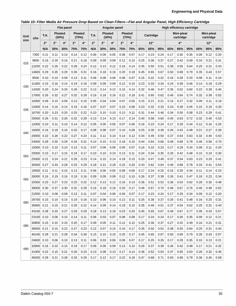
Engineering and Physical Data
025
7300 0.11 0.11 0.10 0.14 0.12 0.06 0.06 0.05 0.08 0.07 0.17 0.23 0.24 0.17 0.30 0.35 0.09 0.12 0.20
9800 0.16 0.18 0.16 0.21 0.18 0.09 0.09 0.09 0.12 0.10 0.25 0.36 0.37 0.27 0.42 0.49 0.16 0.21 0.31
12200 0.22 0.26 0.22 0.28 0.24 0.12 0.13 0.12 0.16 0.14 0.35 0.50 0.51 0.38 0.55 0.64 0.25 0.31 0.43
14600 0.29 0.35 0.29 0.35 0.31 0.16 0.18 0.16 0.20 0.18 0.45 0.65 0.67 0.50 0.69 0.79 0.35 0.43 0.57
030
8500 0.10 0.10 0.09 0.13 0.11 0.06 0.06 0.06 0.08 0.07 0.15 0.22 0.22 0.16 0.28 0.33 0.08 0.11 0.19
11300 0.15 0.16 0.14 0.19 0.16 0.09 0.09 0.09 0.12 0.10 0.23 0.33 0.34 0.24 0.39 0.46 0.14 0.18 0.29
14200 0.20 0.24 0.20 0.26 0.22 0.13 0.14 0.12 0.16 0.14 0.32 0.46 0.47 0.35 0.52 0.60 0.22 0.28 0.40
17000 0.26 0.32 0.27 0.32 0.29 0.16 0.18 0.16 0.21 0.18 0.41 0.60 0.62 0.46 0.64 0.74 0.32 0.39 0.52
035
10000 0.09 0.10 0.09 0.13 0.10 0.05 0.04 0.04 0.07 0.05 0.15 0.21 0.21 0.15 0.27 0.32 0.09 0.11 0.19
13400 0.14 0.16 0.14 0.19 0.16 0.07 0.07 0.07 0.10 0.08 0.23 0.32 0.33 0.24 0.39 0.45 0.15 0.19 0.30
16700 0.20 0.23 0.20 0.25 0.22 0.10 0.10 0.10 0.13 0.11 0.31 0.44 0.46 0.34 0.50 0.58 0.23 0.29 0.41
20000 0.26 0.31 0.26 0.32 0.28 0.13 0.14 0.13 0.17 0.14 0.40 0.58 0.60 0.45 0.63 0.72 0.32 0.40 0.53
040
12000 0.10 0.11 0.10 0.14 0.12 0.05 0.05 0.05 0.07 0.06 0.16 0.23 0.24 0.17 0.29 0.34 0.12 0.16 0.25
16000 0.16 0.18 0.16 0.20 0.17 0.08 0.08 0.07 0.10 0.08 0.25 0.35 0.36 0.26 0.42 0.48 0.21 0.27 0.39
20000 0.22 0.26 0.22 0.27 0.24 0.11 0.11 0.10 0.14 0.12 0.34 0.49 0.50 0.37 0.54 0.63 0.32 0.40 0.53
24000 0.28 0.35 0.29 0.34 0.31 0.14 0.15 0.13 0.18 0.15 0.44 0.64 0.66 0.49 0.68 0.78 0.46 0.56 0.70
050
15000 0.10 0.10 0.10 0.13 0.11 0.07 0.06 0.06 0.09 0.07 0.16 0.22 0.23 0.17 0.29 0.34 0.09 0.11 0.20
20000 0.15 0.17 0.15 0.19 0.17 0.10 0.10 0.10 0.13 0.11 0.24 0.34 0.35 0.26 0.42 0.48 0.15 0.19 0.30
25000 0.21 0.24 0.21 0.26 0.23 0.14 0.15 0.14 0.18 0.15 0.33 0.47 0.49 0.37 0.54 0.63 0.23 0.29 0.41
30000 0.27 0.33 0.28 0.33 0.29 0.18 0.21 0.18 0.23 0.20 0.43 0.62 0.64 0.49 0.68 0.78 0.33 0.41 0.54
065
19500 0.11 0.11 0.10 0.13 0.11 0.06 0.06 0.05 0.08 0.06 0.17 0.24 0.25 0.16 0.29 0.34 0.11 0.14 0.23
26000 0.16 0.19 0.16 0.19 0.16 0.09 0.09 0.08 0.12 0.10 0.26 0.37 0.38 0.26 0.41 0.47 0.18 0.23 0.34
32500 0.23 0.27 0.23 0.25 0.22 0.12 0.13 0.12 0.16 0.13 0.36 0.51 0.53 0.36 0.53 0.62 0.28 0.35 0.48
39000 0.30 0.37 0.30 0.32 0.29 0.16 0.18 0.16 0.20 0.17 0.46 0.67 0.70 0.48 0.67 0.76 0.40 0.49 0.62
080
21500 0.10 0.06 0.09 0.13 0.11 0.07 0.04 0.06 0.09 0.07 0.17 0.23 0.24 0.17 0.29 0.34 0.09 0.12 0.20
28700 0.15 0.10 0.15 0.19 0.16 0.10 0.06 0.10 0.13 0.11 0.25 0.36 0.37 0.26 0.41 0.48 0.16 0.20 0.31
35900 0.21 0.15 0.21 0.26 0.22 0.14 0.09 0.14 0.18 0.15 0.35 0.49 0.51 0.37 0.54 0.62 0.25 0.31 0.43
43100 0.28 0.20 0.27 0.33 0.29 0.18 0.13 0.18 0.23 0.20 0.45 0.65 0.67 0.49 0.67 0.77 0.35 0.43 0.57
085
23100 0.10 0.06 0.10 0.14 0.11 0.06 0.03 0.07 0.08 0.08 0.17 0.24 0.24 0.17 0.30 0.35 0.09 0.12 0.21
30800 0.15 0.10 0.15 0.20 0.17 0.09 0.05 0.11 0.12 0.12 0.25 0.36 0.37 0.27 0.42 0.49 0.16 0.21 0.31
38500 0.21 0.15 0.22 0.27 0.23 0.12 0.07 0.15 0.16 0.17 0.35 0.50 0.52 0.38 0.55 0.64 0.25 0.31 0.44
46100 0.28 0.21 0.28 0.34 0.30 0.15 0.10 0.15 0.20 0.17 0.45 0.65 0.67 0.50 0.69 0.79 0.35 0.43 0.57
090
24600 0.10 0.06 0.10 0.13 0.11 0.06 0.03 0.06 0.09 0.07 0.17 0.25 0.25 0.17 0.29 0.35 0.10 0.13 0.21
32800 0.16 0.10 0.15 0.19 0.17 0.09 0.06 0.09 0.13 0.10 0.26 0.37 0.39 0.26 0.42 0.48 0.17 0.21 0.32
41000 0.22 0.15 0.21 0.26 0.23 0.13 0.08 0.13 0.17 0.14 0.36 0.52 0.54 0.37 0.55 0.63 0.26 0.32 0.45
49200 0.28 0.21 0.28 0.33 0.29 0.17 0.12 0.17 0.22 0.18 0.47 0.68 0.71 0.50 0.68 0.78 0.36 0.45 0.58
Table 10: Filter Media Air Pressure Drop Based on Clean Filters—Flat and Angular Panel, High Efficiency Cartridge
Unitsize
cfm
Flat panel Angular panel High efficiency cartridge
T.A.Pleated (30%)
Pleated (70%)
T.A.Pleated (30%)
Pleated (70%)
CartridgeMini-pleat cartridge
Mini-pleat cartridge
2" 2" 4" 2" 4" 2" 2" 4" 2" 4" 12" 4" 12"
N/A 30% 30% 70% 70% N/A 30% 30% 70% 70% 65% 85% 95% 65% 85% 95% 65% 85% 95%
Daikin Catalog 550-7 35

Engineering and Physical Data
Table 11: Filter Media Air Pressure Drop Based on Clean Filters—High Efficiency Bag
Unitsize
cfm
High efficiency bag
DriPak 2000
36" 30" 22" 19" 15" 12"
65% 85% 95% 65% 85% 95% 65% 85% 95% 45% 45% 45%
003
900 0.15 0.22 0.29 0.15 0.21 0.32 0.17 0.28 0.42 0.11 0.10 0.13
1200 0.20 0.29 0.39 0.19 0.29 0.43 0.23 0.37 0.56 0.18 0.14 0.17
1500 0.24 0.36 0.49 0.24 0.36 0.53 0.28 0.46 0.70 0.25 0.19 0.21
1800 0.29 0.43 0.59 0.29 0.43 0.64 0.33 0.56 0.83 0.33 0.24 0.25
004
1200 0.11 0.16 0.21 0.11 0.16 0.24 0.13 0.21 0.32 0.07 0.07 0.10
1600 0.15 0.21 0.29 0.14 0.21 0.31 0.17 0.27 0.42 0.11 0.10 0.13
2000 0.18 0.27 0.36 0.18 0.26 0.39 0.21 0.34 0.52 0.16 0.13 0.16
2400 0.22 0.32 0.44 0.21 0.32 0.47 0.25 0.41 0.62 0.21 0.16 0.19
006
1700 0.12 0.17 0.22 0.11 0.17 0.25 0.14 0.21 0.33 0.08 0.07 0.11
2300 0.15 0.23 0.31 0.15 0.22 0.33 0.18 0.29 0.44 0.12 0.11 0.14
2900 0.19 0.28 0.39 0.19 0.28 0.42 0.22 0.37 0.55 0.17 0.14 0.17
3500 0.23 0.34 0.47 0.23 0.34 0.51 0.27 0.44 0.66 0.23 0.18 0.20
008
2200 0.13 0.19 0.25 0.13 0.19 0.28 0.15 0.24 0.37 0.09 0.08 0.12
3000 0.17 0.26 0.35 0.17 0.26 0.38 0.20 0.33 0.50 0.15 0.13 0.16
3800 0.22 0.32 0.44 0.22 0.32 0.48 0.26 0.42 0.63 0.21 0.17 0.19
4600 0.26 0.39 0.54 0.26 0.39 0.58 0.31 0.51 0.76 0.28 0.21 0.23
010
2900 0.16 0.23 0.31 0.15 0.23 0.34 0.18 0.30 0.45 0.13 0.11 0.14
3900 0.21 0.31 0.42 0.21 0.31 0.46 0.24 0.40 0.60 0.20 0.16 0.19
4900 0.26 0.39 0.53 0.26 0.39 0.57 0.30 0.50 0.75 0.28 0.21 0.23
5900 — — — — — — — — — — — —
012
3600 0.14 0.21 0.28 0.14 0.20 0.30 0.16 0.26 0.40 0.11 0.09 0.13
4800 0.19 0.27 0.37 0.18 0.27 0.40 0.22 0.35 0.53 0.16 0.14 0.17
6000 0.23 0.34 0.47 0.23 0.34 0.50 0.27 0.44 0.66 0.23 0.18 0.20
7200 0.27 0.41 0.56 0.27 0.41 0.60 0.32 0.53 0.79 0.30 0.23 0.24
014
4200 0.14 0.21 0.28 0.14 0.21 0.31 0.17 0.27 0.41 0.11 0.10 0.13
5400 0.18 0.27 0.36 0.18 0.27 0.40 0.21 0.35 0.52 0.16 0.13 0.16
6600 0.22 0.33 0.45 0.22 0.33 0.48 0.26 0.42 0.64 0.21 0.17 0.20
8800 0.29 0.43 0.60 0.29 0.43 0.65 0.34 0.56 0.84 0.33 0.24 0.25
017
5000 0.14 0.20 0.27 0.13 0.20 0.29 0.16 0.25 0.39 0.10 0.09 0.12
6700 0.18 0.26 0.36 0.18 0.26 0.39 0.21 0.34 0.52 0.15 0.13 0.16
8400 0.22 0.33 0.45 0.22 0.33 0.49 0.26 0.43 0.64 0.22 0.17 0.20
10100 0.27 0.39 0.55 0.27 0.40 0.59 0.31 0.51 0.77 0.29 0.22 0.23
021
6000 0.13 0.20 0.26 0.13 0.19 0.29 0.16 0.25 0.38 0.10 0.09 0.12
8000 0.18 0.26 0.35 0.17 0.26 0.38 0.21 0.33 0.51 0.15 0.13 0.16
10000 0.22 0.32 0.44 0.22 0.32 0.48 0.25 0.42 0.63 0.21 0.17 0.19
12000 0.26 0.39 0.53 0.26 0.39 0.57 0.30 0.50 0.75 0.28 0.21 0.23
025
7300 0.14 0.21 0.28 0.14 0.20 0.30 0.16 0.26 0.40 0.11 0.09 0.13
9800 0.19 0.28 0.37 0.18 0.27 0.41 0.22 0.36 0.54 0.16 0.14 0.17
12200 0.23 0.34 0.47 0.23 0.34 0.51 0.27 0.44 0.66 0.23 0.18 0.20
14600 0.27 0.41 0.56 0.28 0.41 0.61 0.32 0.53 0.79 0.30 0.23 0.24
36 Daikin Catalog 550-7
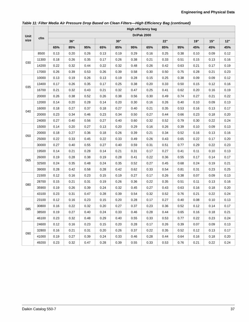
Engineering and Physical Data
030
8500 0.13 0.20 0.26 0.13 0.19 0.29 0.16 0.25 0.38 0.10 0.09 0.12
11300 0.18 0.26 0.35 0.17 0.26 0.38 0.21 0.33 0.51 0.15 0.13 0.16
14200 0.22 0.32 0.44 0.22 0.32 0.48 0.26 0.42 0.63 0.21 0.17 0.19
17000 0.26 0.39 0.53 0.26 0.39 0.58 0.30 0.50 0.75 0.28 0.21 0.23
035
10000 0.13 0.19 0.26 0.13 0.19 0.28 0.15 0.25 0.38 0.09 0.09 0.12
13400 0.17 0.26 0.35 0.17 0.25 0.38 0.20 0.33 0.50 0.15 0.12 0.16
16700 0.21 0.32 0.43 0.21 0.32 0.47 0.25 0.41 0.62 0.20 0.16 0.19
20000 0.26 0.38 0.52 0.26 0.38 0.56 0.30 0.49 0.74 0.27 0.21 0.22
040
12000 0.14 0.20 0.28 0.14 0.20 0.30 0.16 0.26 0.40 0.10 0.09 0.13
16000 0.18 0.27 0.37 0.18 0.27 0.40 0.21 0.35 0.53 0.16 0.13 0.17
20000 0.23 0.34 0.46 0.23 0.34 0.50 0.27 0.44 0.66 0.23 0.18 0.20
24000 0.27 0.40 0.56 0.27 0.40 0.60 0.32 0.52 0.79 0.30 0.22 0.24
050
15000 0.14 0.20 0.27 0.13 0.20 0.29 0.16 0.26 0.39 0.10 0.09 0.13
20000 0.18 0.27 0.36 0.18 0.26 0.39 0.21 0.34 0.52 0.16 0.13 0.16
25000 0.22 0.33 0.45 0.22 0.33 0.49 0.26 0.43 0.65 0.22 0.17 0.20
30000 0.27 0.40 0.55 0.27 0.40 0.59 0.31 0.51 0.77 0.29 0.22 0.23
065
19500 0.14 0.21 0.28 0.14 0.21 0.31 0.17 0.27 0.41 0.11 0.10 0.13
26000 0.19 0.28 0.38 0.19 0.28 0.41 0.22 0.36 0.55 0.17 0.14 0.17
32500 0.24 0.35 0.48 0.24 0.35 0.52 0.27 0.45 0.68 0.24 0.19 0.21
39000 0.28 0.42 0.58 0.28 0.42 0.62 0.33 0.54 0.81 0.31 0.23 0.25
080
21500 0.12 0.16 0.23 0.15 0.19 0.27 0.17 0.26 0.38 0.07 0.09 0.13
28700 0.15 0.21 0.31 0.19 0.26 0.36 0.22 0.35 0.51 0.11 0.13 0.16
35900 0.19 0.26 0.39 0.24 0.32 0.45 0.27 0.43 0.63 0.16 0.18 0.20
43100 0.23 0.31 0.47 0.28 0.39 0.54 0.32 0.52 0.76 0.21 0.22 0.24
085
23100 0.12 0.16 0.23 0.15 0.20 0.28 0.17 0.27 0.40 0.08 0.10 0.13
30800 0.16 0.22 0.32 0.20 0.27 0.37 0.23 0.36 0.52 0.12 0.14 0.17
38500 0.19 0.27 0.40 0.24 0.33 0.46 0.28 0.44 0.65 0.16 0.18 0.21
46100 0.23 0.32 0.48 0.29 0.40 0.55 0.33 0.53 0.77 0.22 0.23 0.24
090
24600 0.12 0.16 0.23 0.15 0.20 0.28 0.17 0.26 0.39 0.07 0.09 0.13
32800 0.16 0.21 0.31 0.20 0.26 0.37 0.22 0.35 0.52 0.12 0.13 0.17
41000 0.19 0.27 0.39 0.24 0.33 0.46 0.28 0.44 0.64 0.16 0.18 0.20
49200 0.23 0.32 0.47 0.28 0.39 0.55 0.33 0.53 0.76 0.21 0.22 0.24
Table 11: Filter Media Air Pressure Drop Based on Clean Filters—High Efficiency Bag (continued)
Unitsize
cfm
High efficiency bag
DriPak 2000
36" 30" 22" 19" 15" 12"
65% 85% 95% 65% 85% 95% 65% 85% 95% 45% 45% 45%
Daikin Catalog 550-7 37

Engineering and Physical Data
Figure 21: Coil Air Pressure Drop—HI-F5 Fin Type (2 Through 12 Rows)
Notes:• The letters A,B,C,D or E following the face velocity indicate the degree of wetness at which the coil is operating.• Dry coils are shown by the letter A, wet coils by the letter E. Intermediate conditions are shown by the letters B, C, and D.• Air pressure drop for odd fin spacings can be found by interpolation.
2 3 4 5 6 8 10 12ROWSROWS
1.0
2.0 2.5
1.4
1.8
2.0
1.6
1.2.80
1.8
1.6
1.01.4
1.4
1.2
1.0.80.60.40
1.2.90.60
.80.50
.70 .90
.90.70.50
.80.60.30
.70.40
.50.60
.50.40.30.20
.25.40
.30.15
.20.25
.30
.25.20.15.10
.20.08.15
.10
.15.09.06
.08
.07
1.0
.05 .10
.09
.10.08.06.04
.09
14
12
10
08
06
14121008
06
3.0 4.0 5.0 6.0
5.04.0
2.5
3.0
2.02.5 4.0
3.6
3.2
2.8
2.4
2.0
1.8
1.6
1.41.2
1.0
.80
.60
.50
.40
.30
.20
3.0
2.5
2.0
1.8
1.6
1.4
1.0 1.2
.90
.80
.70
.60
.50
.40
.30
.25
.20
2.0
1.8
1.6
1.4
1.2
1.0
.90
.80
.70
.60
.50
.40
.30
.25
.20
.15
1.8
1.6
1.4
1.2
1.0
.90
.80
.70
.60
.50
.40
.30
.25
.20
.15
.10
E
D
C
B
A
E
D
C
B
A
FACE VELOCITY, FPM200 250 300 400 500 600 700 800
AIR
PR
ES
SU
RE
DR
OP,
INC
HE
S IN
WA
TE
R
FIN
SE
RIE
S
FIN
SE
RIE
S
SHRDEGREE
OFWETNESS
ABCDE
MAX. FACE VEL.Without Water Blowoff(Does not apply to A)
1.0 - .98.98 - .92.92 - .86.86 - .80
.80 or Less
38 Daikin Catalog 550-7

Engineering and Physical Data
Figure 22: Coil Air Pressure Drop—E-F5 Fin Type (2 Through 12 Rows)
Notes:• The letters A,B,C,D or E following the face velocity indicate the degree of wetness at which the coil is operating.• Dry coils are shown by the letter A, wet coils by the letter E. Intermediate conditions are shown by the letters B, C, and D.• Air pressure drop for odd fin spacings can be found by interpolation.
2 3ROWS
14
12
10
08
06
2.0
E
D
C
B
A
FACE VELOCITY, FPM200 250 300 400 500 600 700 800
AIR
PR
ES
SU
RE
DR
OP,
INC
HE
S IN
WA
TE
R
FIN
SE
RIE
S
SHRDEGREE
OFWETNESS
1.0 - .98.98 - .92.92 - .86.86 - .80
.80 or Less
ABCDE
MAX. FACE VEL.Without Water Blowoff(Does not apply to A)
E
D
C
B
A350
4 5 6 8 10 12ROWS
14
12
10
08
06
FIN
SE
RIE
S
1.5 3.0
2.0 4.0
1.5 3.0
1.0 1.5 2.0 3.0
.80 1.0 2.01.5
2.01.0.80
.60.80
1.51.6
.50 1.0.60
.40 .50 .60 .80 1.0 1.2
.50 1.0.40 .80
.30 .60
.40 .80
.30 .60.50
.20 .30 .40 .50 .60
.20 .40.15 .30
.20 .40
.15 .30
.10 .15 .20 .30
.08 .10 .20.15
.10 .20.08
.06 .15
.08 .16.05
.06.10
.05.04 .06 .08 .10 .12
.80
1.0
.60
.80.50
.40 .60
.50
.30
.40
.20 .30
.15
.20
.15.10
.08
.10.06
.08.05
.04 .06
.05
.04
.03
.03.02
Daikin Catalog 550-7 39

Engineering and Physical Data
Figure 23: Coil Air Pressure Drop—HI-F5 Fin Type
Note:Air pressure drop for odd fin spacings can be found by interpolation.
Figure 24: Coil Air Pressure Drop—E-F5 Fin Type
HI-F5
300
.07
.15
.20
.25
.30
.60
1.51.5
3.03.0
1ROW
2ROW
.10
400 500 600 700 800 1000 1500
STANDARD AIR FACE VELOCITY - FT/MIN
AIR
PR
ES
SU
RE
DR
OP
- IN
CH
ES
OF
WA
TE
R
2.52.5
2.02.0
.90.90
1.01.0
.80
.40
.09
.08
.50
.03
.04
.05
.06
.07
.08
.09
.10
.15.15
.20.20
.25.25
.30.30
.40.40
.50.50
.60.60
.70.70
.80.80
.90.90
1.01.0
1.51.5
14
06
08
1012
FIN
SE
RIE
S
.70
E-F5
300
.07
.15
.20
.25
.30
.60
.70
1.5
3.0
1ROW
2ROW
.10
400 500 600 700 800 1000 1500
STANDARD AIR FACE VELOCITY - FT/MIN
AIR
PR
ES
SU
RE
DR
OP
- IN
CH
ES
OF
WA
TE
R
2.5
2.0
.90
1.0
.80
.40
.09
.08
.50
14
06
08
10
12
FIN
SE
RIE
S
.20
.25
.30
.40
.50
.60
.70
.80
.90
1.0
1.5
.10
.09
.08
.07
.06
.05
.04
.03
.15
40 Daikin Catalog 550-7

Engineering and Physical Data
Figure 25: 1" Steam Coil Air Pressure Drop
Note:Air pressure drop for odd fin spacings can be found by interpolation.
HI-F8
300 400 500 600 700 800 1000 1500
STANDARD AIR FACE VELOCITY - FT/MIN
1ROW
AIR
PR
ES
SU
RE
DR
OP
- IN
CH
ES
OF
WA
TE
R
.03
.025
.02
.04
.05
.06
.07
.08
.09
.10
.15
.20
.25
.30
.40
.50
.60
.70
.80
.90
1.0
1.5
2.0
03
04
06
08
10
12
14
FIN
SE
RIE
S
Daikin Catalog 550-7 41
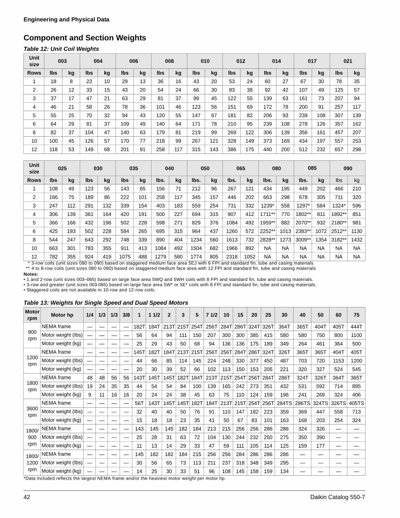
Engineering and Physical Data
Component and Section Weights
* 3-row coils (unit sizes 080 to 090) based on staggered medium face area 5EJ with 6 FPI and standard fin, tube and casing materials.** 4 to 8-row coils (unit sizes 080 to 090) based on staggered medium face area with 12 FPI and standard fin, tube and casing materials
Notes:• 1 and 2-row (unit sizes 003–065) based on large face area 5WQ and 5WH coils with 8 FPI and standard fin, tube and casing materials.• 3-row and greater (unit sizes 003-065) based on large face area 5W* or 5E* coils with 8 FPI and standard fin, tube and casing materials.• Staggered coils are not available in 10-row and 12-row coils.
*Data included reflects the largest NEMA frame and/or the heaviest motor weight per motor hp.
Table 12: Unit Coil Weights
Unit size
003 004 006 008 010 012 014 017 021
Rows lbs kg lbs kg lbs kg lbs kg lbs kg lbs kg lbs kg lbs kg lbs kg
1 18 8 23 10 29 13 36 16 43 20 53 24 60 27 67 30 78 35
2 26 12 33 15 43 20 54 24 66 30 83 38 92 42 107 49 125 57
3 37 17 47 21 63 29 81 37 99 45 122 55 139 63 161 73 207 94
4 46 21 58 26 78 36 101 46 123 56 151 69 172 78 200 91 257 117
5 55 25 70 32 94 43 120 55 147 67 181 82 206 93 239 108 307 139
6 64 29 81 37 109 49 140 64 171 78 210 95 239 108 278 126 357 162
8 82 37 104 47 140 63 179 81 219 99 269 122 306 139 356 161 457 207
10 100 45 126 57 170 77 218 99 267 121 328 149 373 169 434 197 557 253
12 118 53 149 68 201 91 258 117 315 143 386 175 440 200 512 232 657 298
Unit size
025 030 035 040 050 065 080 085 090
Rows lbs kg lbs kg lbs kg lbs. kg lbs. kg lbs. kg lbs. kg lbs. kg lbs kg
1 108 49 123 56 143 65 156 71 212 96 267 121 434 195 449 202 466 210
2 166 75 189 86 222 101 258 117 345 157 446 202 663 298 678 305 711 320
3 247 112 291 132 339 154 403 183 559 254 731 332 1239* 558 1297* 584 1324* 596
4 306 139 361 164 420 191 500 227 694 315 907 412 1711** 770 1802** 811 1892** 851
5 366 166 432 196 502 228 598 271 829 376 1084 492 1959** 882 2070** 932 2180** 981
6 425 193 502 228 584 265 695 315 964 437 1260 572 2252** 1013 2383** 1072 2512** 1130
8 544 247 643 292 748 339 890 404 1234 560 1613 732 2828** 1273 3009** 1354 3182** 1432
10 663 301 783 355 911 413 1084 492 1504 682 1966 892 NA NA NA NA NA NA
12 782 355 924 419 1075 488 1279 580 1774 805 2318 1052 NA NA NA NA NA NA
Table 13: Weights for Single Speed and Dual Speed Motors
Motor rpm
Motor hp 1/4 1/3 1/3 3/8 1 1 1/2 2 3 5 7 1/2 10 15 20 25 30 40 50 60 75
900 rpm
NEMA frame — — — — 182T 184T 213T 215T 254T 256T 284T 286T 324T 326T 364T 365T 404T 405T 444T
Motor weight (Ibs) — — — — 56 64 94 111 150 207 300 300 385 415 580 580 750 800 1100
Motor weight (kg) — — — — 25 29 43 50 68 94 136 136 175 189 349 264 461 364 500
1200 rpm
NEMA frame — — — — 145T 182T 184T 213T 215T 256T 256T 284T 286T 324T 326T 365T 365T 404T 405T
Motor weight (Ibs) — — — — 44 66 85 114 145 224 248 330 377 450 487 703 720 1153 1200
Motor weight (kg) — — — — 20 30 39 52 66 102 113 150 153 205 221 320 327 524 545
1800 rpm
NEMA frame 48 48 56 56 143T 145T 145T 182T 184T 213T 215T 254T 256T 284T 286T 324T 326T 364T 365T
Motor weight (Ibs) 19 24 35 35 44 54 54 84 100 139 165 242 273 351 432 531 592 714 895
Motor weight (kg) 9 11 16 16 20 24 24 38 45 63 75 110 124 159 196 241 269 324 406
3600 rpm
NEMA frame — — — — 56T 143T 145T 145T 182T 184T 213T 215T 254T 256T 284TS 286TS 324TS 326TS 405TS
Motor weight (Ibs) — — — — 32 40 40 50 76 91 110 147 182 223 359 369 447 558 713
Motor weight (kg) — — — — 15 18 18 23 35 41 50 67 83 101 163 168 203 254 324
1800/900 rpm
NEMA frame — — — — 143 145 145 182 184 213 215 256 256 286 286 324 326 — —
Motor weight (Ibs) — — — — 25 28 31 63 72 104 130 244 232 250 275 350 390 — —
Motor weight (kg) — — — — 11 13 14 29 33 47 59 111 105 114 125 159 177 — —
1800/1200 rpm
NEMA frame — — — — 145 182 182 184 215 256 256 284 286 286 286 — — — —
Motor weight (Ibs) — — — — 30 56 65 73 113 211 237 318 348 349 295 — — — —
Motor weight (kg) — — — — 14 25 30 33 51 96 108 145 158 159 134 — — — —
42 Daikin Catalog 550-7

Engineering and Physical Data
Notes:• Weight factor for 6" high rail = .52 lb/in (.00929 kg/mm)• Weight factor for 10" high rail = .74 lb/in (.0132 kg/mm)
The base rail weight is determined by adding together the weight of the rail supports that run the length and width of the unit. The lengthwise support depends on the overall unit length. The cross member weight is dependent on the number of cross channels needed to support the unit. Each shipping section has a cross member located on each end. When a unit ships in one piece, the rail will have 2 end channel supports. When the unit ships in numerous shipping sections, each shipping section will have two end pieces. Fan, coil, and attenuator sections each must have additional cross member support on the entering and leaving air side of the section. If the coil section is adjacent to a fan, only one cross member is provided between them. A heating only coil section must have an additional cross member support on the entering air side. Any shipping section over 8' long requires an additional cross member.
Base rails are required on sizes 025 and above.
Example:
Determine the weight of a 6" high base rail for a size 8 unit that is 108" long, consisting of a fan, access, coil, and angular filter in a single shipping section.
Weight factor for unit length for a 6" curb is .52 lb/in
108" × .52 lb/in = 56 lb . . . . . . . . . . . . . . . . . . . . . . . . 56 lb
Weight of end cross members for each shipping section is 41 lb each pair.
1 × 41 lb = 41 lb. . . . . . . . . . . . . . . . . . . . . . . . . . . . . . 41 lb
Weight of additional cross members to support fan and coil sections. In this example the fan and coil are separated by an access section; therefore four extra cross member pieces are required for the fan and coil.
4 × 15 = 60 lb . . . . . . . . . . . . . . . . . . . . . . . . . . . . . . . . 60 lb
Total base rail weight . . . . . . . . . . . . . . . . . . . . . . . . 157 lb
Table 14: Base Rail Weights
6" Base rail weights
Standard unit nominal size
003 004 006 008 010 012 014 017 021
lbs kg lbs kg lbs kg lbs kg lbs kg lbs kg lbs kg lbs kg lbs kg
End cross members (pair) 29 13 30 14 37 17 41 19 45 20 46 21 51 23 55 25 56 25
Add’l. cross member supports 10 5 10 5 14 6 15 7 17 8 17 8 19 9 21 10 21 10
6" Base rail weights
Standard unit nominal size
025 030 035 040 050 065 080 085 090
lbs kg lbs kg lbs kg lbs kg lbs kg lbs kg lbs kg lbs kg lbs. kg
End cross members (pair) 57 26 63 29 65 29 68 31 71 32 75 34 75 34 75 34 75 34
Add’l. cross member supports 22 10 26 12 27 12 30 14 32 15 35 16 35 16 35 16 35 16
10" Base rail weights
Standard unit nominal size
003 004 006 008 010 012 014 017 021
lbs kg lbs kg lbs kg lbs kg lbs kg lbs kg lbs kg lbs kg lbs kg
End cross members (pair) 39 18 40 18 50 23 55 25 60 27 62 28 69 31 74 33 75 34
Add’l. cross member supports 14 6 15 7 19 9 21 10 24 11 24 11 27 12 30 14 30 14
10" Base rail weights
Standard unit nominal size
025 030 035 040 050 065 080 085 090
lbs kg lbs kg lbs kg lbs kg lbs kg lbs kg lbs kg lbs kg lbs kg
End cross members (pair) 78 35 86 39 89 40 92 42 95 43 107 49 107 49 107 49 107 49
Add’l. cross member supports 32 15 36 16 38 17 43 20 47 21 50 23 50 23 50 23 50 23
Daikin Catalog 550-7 43

Engineering and Physical Data
Fan Data
Figure 26: Torque for FC Variable Inlet Vanes (in-lb), Unit Sizes 003 to 035
Note: Inlet vanes on fans 30 hp or more are not acceptable perASHRAE 90.1-1999.
Figure 27: Torque for AF Variable Inlet Vanes (in-lb), Unit Sizes 003 to 035
Note: Inlet vanes on fans 30 hp or more are not acceptable perASHRAE 90.1-1999.
Table 15: Physical Data, Forward Curved and Airfoil Housed Fans, Unit Sizes 003 to 035
Forward curved—English units
Diameter Class I (inches) 9 × 4 9 × 7 9 × 9 10.62 12.62 15 18 20 22.25 24.5
Maximum rpm N/A 2189 2223 1934 1614 1328 1155 1050 944 858
Shaft and bearing diameter (inches) N/A 1 1 1 1 1.188 1.188 1.938 2.1875 2.1875
Outlet area (square feet) N/A 0.65 0.84 1.04 1.46 2.05 2.87 5.18 6.27 7.63
Diameter Class Il (inches) 9 × 4 9 × 7 9 × 9 10.62 12.62 15 18 20 22.25 24.5
Maximum rpm 2244 2854 2896 2518 2091 1725 1450 1200 1030 910
Shaft and bearing diameter (inches) 1 1 1 1 1.188 1.188 1.938 2.188 2.4375 2.4375
Outlet area (square feet) 0.48 0.65 0.84 1.04 1.46 2.05 2.87 5.18 6.27 7.63
Forward curved—SI units
Diameter Class I (millimeters) 229 × 102 229 × 178 229 × 229 270 321 381 457 508 565 622
Maximum rpm N/A 2189 2223 1934 1614 1328 1155 1050 944 858
Shaft & bearing diameter (millimeters) N/A 25 25 25 25 30 30 49 56 56
Outlet area (square meters) N/A 0.060 0.078 0.097 0.136 0.190 0.267 0.481 0.58 0.71
Diameter Class II (millimeters) 229 × 102 229 ×178 229 × 229 270 321 381 457 508 565 622
Maximum rpm 2244 2854 2896 2518 2091 1725 1450 1432 944 858
Shaft and bearing diameter (millimeters) 25 25 25 25 30 30 49 56 62 62
Outlet area (square meters) 0.045 0.060 0.078 0.097 0.136 0.190 0.267 0.481 0.58 0.71
Airfoil—English units
Diameter Class I (inches) 13.22 14.56 16.19 19.69 21.56 24
Maximum rpm 3000 3000 2300 2000 1700 1500
Shaft and bearing diameter (inches) 1.188 1.438 1.438 1.938 1.938 2.1875
Outlet area (square feet) 2.11 2.85 3.52 4.68 5.82 7.01
Diameter Class II (inches) 13.22 14.56 16.19 19.69 21.56 24
Maximum rpm 4335 3918 3457 2858 2547 2255
Shaft and bearing diameter (inches) 1.438 1.688 1.688 2.188 2.438 2.4375
Outlet area (square feet) 2.11 2.85 3.52 4.68 5.82 7.01
Airfoil—SI units
Diameter Class I (millimeters) 336 370 411 500 548 610
Maximum rpm 3000 3000 2300 2000 1700 1500
Shaft and bearing diameter (millimeters) 30 37 37 49 49 56
Outlet area (square meters) 0.196 0.265 0.327 0.435 0.541 0.65
Diameter Class II (millimeters) 336 370 411 500 548 610
Maximum rpm 4335 3918 3457 2858 2547 2547
Shaft and bearing diameter (millimeters) 37 43 43 56 62 62
Outlet area (square meters) 0.196 0.265 0.327 0.435 0.541 0.65
FC24.5
0300
250
200
150
1009080
70
60
50
Torq
ue (
in.-
lb.)
Fan Speed (rpm)
800
850
900
1000
1500
2000
400
500
600
700
350
450
550
650
750
FC22.2
5
FC20.0
0
FC18.00
FC15.00
FC12.62
Fan Speed (rpm)
750
800
850
900
1000
1500
2000
2500
3000
3500
4500
4000
500
400350300250
200
150
10090807060
50403530
AF13.22
AF24.00
AF21.56
AF19.69
AF16.19
AF14.56
Torq
ue (
in.-
lb.)
44 Daikin Catalog 550-7
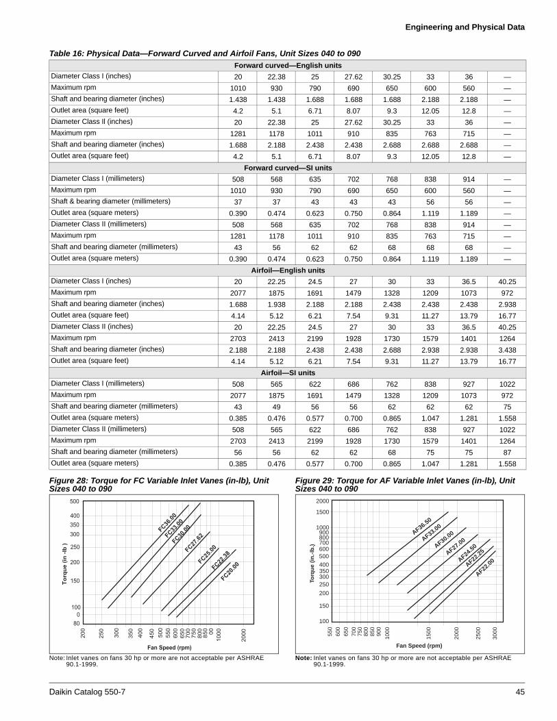
Engineering and Physical Data
Figure 28: Torque for FC Variable Inlet Vanes (in-lb), Unit Sizes 040 to 090
Note: Inlet vanes on fans 30 hp or more are not acceptable per ASHRAE 90.1-1999.
Figure 29: Torque for AF Variable Inlet Vanes (in-lb), Unit Sizes 040 to 090
Note: Inlet vanes on fans 30 hp or more are not acceptable per ASHRAE 90.1-1999.
Table 16: Physical Data—Forward Curved and Airfoil Fans, Unit Sizes 040 to 090
Forward curved—English units
Diameter Class I (inches) 20 22.38 25 27.62 30.25 33 36 —
Maximum rpm 1010 930 790 690 650 600 560 —
Shaft and bearing diameter (inches) 1.438 1.438 1.688 1.688 1.688 2.188 2.188 —
Outlet area (square feet) 4.2 5.1 6.71 8.07 9.3 12.05 12.8 —
Diameter Class Il (inches) 20 22.38 25 27.62 30.25 33 36 —
Maximum rpm 1281 1178 1011 910 835 763 715 —
Shaft and bearing diameter (inches) 1.688 2.188 2.438 2.438 2.688 2.688 2.688 —
Outlet area (square feet) 4.2 5.1 6.71 8.07 9.3 12.05 12.8 —
Forward curved—SI units
Diameter Class I (millimeters) 508 568 635 702 768 838 914 —
Maximum rpm 1010 930 790 690 650 600 560 —
Shaft & bearing diameter (millimeters) 37 37 43 43 43 56 56 —
Outlet area (square meters) 0.390 0.474 0.623 0.750 0.864 1.119 1.189 —
Diameter Class II (millimeters) 508 568 635 702 768 838 914 —
Maximum rpm 1281 1178 1011 910 835 763 715 —
Shaft and bearing diameter (millimeters) 43 56 62 62 68 68 68 —
Outlet area (square meters) 0.390 0.474 0.623 0.750 0.864 1.119 1.189 —
Airfoil—English units
Diameter Class I (inches) 20 22.25 24.5 27 30 33 36.5 40.25
Maximum rpm 2077 1875 1691 1479 1328 1209 1073 972
Shaft and bearing diameter (inches) 1.688 1.938 2.188 2.188 2.438 2.438 2.438 2.938
Outlet area (square feet) 4.14 5.12 6.21 7.54 9.31 11.27 13.79 16.77
Diameter Class II (inches) 20 22.25 24.5 27 30 33 36.5 40.25
Maximum rpm 2703 2413 2199 1928 1730 1579 1401 1264
Shaft and bearing diameter (inches) 2.188 2.188 2.438 2.438 2.688 2.938 2.938 3.438
Outlet area (square feet) 4.14 5.12 6.21 7.54 9.31 11.27 13.79 16.77
Airfoil—SI units
Diameter Class I (millimeters) 508 565 622 686 762 838 927 1022
Maximum rpm 2077 1875 1691 1479 1328 1209 1073 972
Shaft and bearing diameter (millimeters) 43 49 56 56 62 62 62 75
Outlet area (square meters) 0.385 0.476 0.577 0.700 0.865 1.047 1.281 1.558
Diameter Class II (millimeters) 508 565 622 686 762 838 927 1022
Maximum rpm 2703 2413 2199 1928 1730 1579 1401 1264
Shaft and bearing diameter (millimeters) 56 56 62 62 68 75 75 87
Outlet area (square meters) 0.385 0.476 0.577 0.700 0.865 1.047 1.281 1.558
� � �
� � �
� � �
� � �
� � �
� � �
� � �
�
�
������� ���
� � � � � � � � � � � �
��
��
��
����
����
���
���
��
���
���
���
���
��
���
� � �
���
���
���
� �� �� ��
� �� �� ��
� �� �� ��
� �� �� ��
� �� �� ��
� �� �� ��
� �� �� ��
500400350
250
200
150
100
Torq
ue
(in
.-lb
.)
Fan Speed (rpm)
800
850
900
1000
200060
0
700
550
650
750
300
1500
2500
3000
700800900
1000
1500
2000
600
AF36.50
AF33.00
AF30.00
AF27.00
AF24.50
AF22.25
AF22.00
Daikin Catalog 550-7 45

Engineering and Physical Data
Figure 30: Torque for Inlet Vane at 100% WOV (lb-in) for SWSI Plenum Fans with Nested Inlet Vanes
Note: Inlet vanes on fans 30 hp or more are not acceptable per ASHRAE 90.1-1999.
Table 17: Physical Data—Belt Drive Plenum Fans
Fan Size 13 15 16 18 20 22 24 27 30 33 36 40 44 49 54 60
Plenum—English units
Diameter Class Il (inches)
13.56 15.25 17.88 18.25 20.0 22.25 24.5 27.0 30.0 33.0 36.5 40.25 44.5 49.0 54.25 60.0
Maximum rpm 3909 3468 2820 2930 2674 2403 2183 1860 1783 1620 1465 1329 1202 1091 986 891
Shaft and bearing diameter (inches)
1.1875 1.1875 1.1875 1.4375 1.4375 1.6875 1.6875 1.6875 1.9375 2.1875 2.1875 2.1875 2.4375 2.4375 2.4375 2.9375
Outlet area (square feet)
N/A N/A N/A N/A N/A N/A N/A N/A N/A N/A N/A N/A N/A N/A N/A N/A
Plenum—SI units
Diameter Class II (millimeters)
344 387 454 464 508 565 622 686 762 838 927 1022 1130 1245 1378 1524
Maximum rpm 3909 3468 2820 2930 2674 2403 2183 1860 1783 1620 1465 1329 1202 1091 986 3909
Shaft and bearing diameter
(millimeters)30.2 30.2 30.2 36.5 36.5 42.9 42.9 42.9 42.9 55.6 55.6 55.6 61.9 61.9 61.9 74.6
Outlet area (square meters)
N/A N/A N/A N/A N/A N/A N/A N/A N/A N/A N/A N/A N/A N/A N/A N/A
600
700
600
500
400
100
900
300
200
Torq
ue (
lb./i
n.)
Fan Speed (rpm)
800
900
1000
1500
2000
400
500
600
700
300
200
3000
800
1000
2000
3000
4000
500054
249
044
540
236
533
030
027
024
5
46 Daikin Catalog 550-7
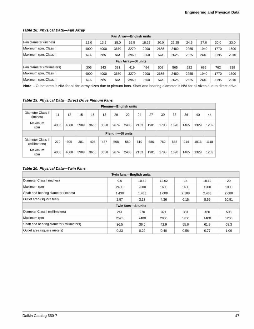
Engineering and Physical Data
Table 18: Physical Data—Fan Array
Fan Array—English units
Fan diameter (inches) 12.0 13.5 15.0 16.5 18.25 20.0 22.25 24.5 27.0 30.0 33.0
Maximum rpm, Class I 4000 4000 3670 3270 2900 2685 2480 2255 1940 1770 1590
Maximum rpm, Class II N/A N/A N/A 3960 3660 N/A 2625 2625 2440 2195 2010
Fan Array—SI units
Fan diameter (millimeters) 305 343 381 419 464 508 565 622 686 762 838
Maximum rpm, Class I 4000 4000 3670 3270 2900 2685 2480 2255 1940 1770 1590
Maximum rpm, Class II N/A N/A N/A 3960 3660 N/A 2625 2625 2440 2195 2010
Note – Outlet area is N/A for all fan array sizes due to plenum fans. Shaft and bearing diameter is N/A for all sizes due to direct drive.
Table 19: Physical Data—Direct Drive Plenum Fans
Plenum—English units
Diameter Class Il (inches)
11 12 15 16 18 20 22 24 27 30 33 36 40 44
Maximum rpm
4000 4000 3909 3650 3650 2674 2403 2183 1981 1783 1620 1465 1329 1202
Plenum—SI units
Diameter Class II (millimeters)
279 305 381 406 457 508 559 610 686 762 838 914 1016 1118
Maximumrpm
4000 4000 3909 3650 3650 2674 2403 2183 1981 1783 1620 1465 1329 1202
Table 20: Physical Data—Twin Fans
Twin fans—English units
Diameter Class I (inches) 9.5 10.62 12.62 15 18.12 20
Maximum rpm 2400 2000 1600 1400 1200 1000
Shaft and bearing diameter (inches) 1.438 1.438 1.688 2.188 2.438 2.688
Outlet area (square feet) 2.57 3.13 4.36 6.15 8.55 10.91
Twin fans—SI units
Diameter Class I (millimeters) 241 270 321 381 460 508
Maximum rpm 2575 2400 2000 1700 1400 1200
Shaft and bearing diameter (millimeters) 36.5 36.5 42.9 55.6 61.9 68.3
Outlet area (square meters) 0.23 0.29 0.40 0.56 0.77 1.00
Daikin Catalog 550-7 47

Engineering and Physical Data
Coil DataTable 21: Unit Coil Dimensional Data—English Units of Measure
Standard chilled water, DX, or 3-row and 4-row heating coils(English units—inches and square feet)
Cleanable coils or 1-row and 2-row heating coils(English units—inches and square feet)
Unit size
Ext/StaggLarge
Ext/StaggMedium Small
Ext/StaggLarge
Ext/StaggMedium Small
Large Medium Large Medium
003FH × FL 18 × 3 1 18 × 25 12 × 31 12 × 25 — FH × FL 18 × 28 18 × 22 12 × 28 12 × 22 —
Face area 3.9 3.1 2.6 2.1 — Face area 3.5 2.8 2.3 1.8 —
004FH × FL 21 × 33 21 × 27 15 × 33 15 × 27 12 × 27 FH × FL 21 × 30 21 × 24 15 × 30 15 × 24 12 × 24
Face area 4.8 3.9 3.4 2.8 2.3 Face area 4.4 3.5 3.1 2.5 2
006FH × FL 21 × 45 21 × 39 15 × 45 15 × 39 12 × 39 FH × FL 21 × 42 21 × 36 15 × 42 15 × 36 12 × 36
Face area 6.6 5.7 4.7 4.1 3.3 Face area 6.1 5.3 4.4 3.8 3
008FH × FL 24 × 51 24 × 45 18 × 51 18 × 45 15 × 45 FH × FL 24 × 48 24 × 42 18 × 48 18 × 42 15 × 42
Face area 8.5 7.5 6.4 5.6 4.7 Face area 8 7 6 5.3 4.4
010FH × FL 27 × 57 27 × 51 21 × 57 21 × 51 18 × 51 FH × FL 27 × 54 27 × 48 21 × 54 21 × 48 18 × 48
Face area 10.7 9.6 8.3 7.4 6.4 Face area 10.1 9 7.9 7 6
012FH × FL 33 × 59 33 × 53 24 × 59 24 × 53 21 × 53 FH × FL 33 × 56 33 × 50 24 × 56 24 × 50 21 × 50
Face area 13.5 12.1 9.8 8.8 7.7 Face area 12.8 11.5 9.3 8.3 7.3
014FH × FL 33 × 67 33 × 61 24 × 67 24 × 61 21 × 61 FH × FL 33 × 64 33 × 58 24 × 64 24 × 58 21 × 58
Face area 15.4 14 11.2 10.2 8.9 Face area 14.7 13.3 10.7 9.7 8.5
017FH × FL 36 × 73 36 × 67 27 × 73 27 × 67 24 × 67 FH × FL 36 × 70 36 × 64 27 × 70 27 × 64 24 × 64
Face area 18.3 16.8 13.7 12.6 11.2 Face area 17.5 16 13.1 12 10.7
021FH × FL 42 × 75 42 × 69 33 × 75 33 × 69 30 × 69 FH × FL 42 × 72 42 × 66 33 × 72 33 × 66 30 × 66
Face area 21.9 20.1 17.2 15.8 14.4 Face area 21 19.3 16.5 15.1 13.8
025
FH × FL 48 × 79 48 × 73 — 36 × 73 33 × 73 FH × FL — — 42 × 70 36 × 70 33 × 70Face area 26.3 24.3 — 18.2 16.7 Face area — — 20.4 17.5 16FH × FL (2) 27 × 73 (2) 24 × 73 (2) 21 × 73 — — FH × FL (2) 27 × 70 (2) 24 × 70 — — —
Face area 27.4 24.3 21.3 — — Face area 26.2 23.3 — — —
030
FH × FL 48 × 91 48 × 85 — 36 × 85 33 × 85 FH × FL — — 42 × 82 36 × 82 33 × 82Face area 30.3 28.3 — 21.2 19.5 Face area — — 23.9 20.5 18.8FH × FL (2) 27 × 85 (2) 24 × 85 (2) 21 × 85 — — FH × FL (2) 27 × 82 (2) 24 × 82 — — —
Face area 31.9 28.3 24.8 — — Face area 30.8 27.3 — — —
035
FH × FL 54 × 95 54 × 89 — 42 × 89 39 × 89 FH × FL — — — 42 × 86 39 × 86Face area 35.6 33.4 — 24.1 22.3 Face area — — — 23.3 21.5FH × FL (2) 30 × 89 (2) 27 × 89 (2) 24 × 89 — — FH × FL (2) 30 × 86 (2) 27 × 86 (2) 24 × 86 — —
Face area 37.1 33.4 29.7 — — Face area 35.8 32.3 28.7 — —
040
FH × FL 54 × 109 54 × 103 — 42 × 103 39 × 103 FH × FL — — — 42 × 100 39 × 100Face area 40.9 38.6 — 30 27.9 Face area — — — 29.2 27.1FH × FL (2) 30 × 103 (2) 27 × 103 (2) 24 × 103 — — FH × FL (2) 30 × 100 (2) 27 × 100 (2) 24 × 100 — —
Face area 42.9 38.6 34.3 — — Face area 41.7 37.5 33.3 — —
050
FH × FL — — — 48 × 107 42 × 107 FH × FL — — — — 42 × 104Face area — — — 35.7 31.2 Face area — — — — 30.3FH × FL (2) 39×107 (2) 33 × 107 (2) 27 × 107 (2) 24 × 107 — FH × FL (2) 39 × 104 (2) 33 × 104 (2) 2 7× 10⁴ (2) 24 × 104 —
Face area 58 49 40.1 35.7 — Face area 56.3 47.7 39 34.7 —
065
FH × FL — — — — 54 × 123 FH × FL — — — — —Face area — — — — 46.1 Face area — — — — —FH × FL (2) 45 × 123 (2) 39 × 123 (2) 36 × 123 (2) 30 × 123 (2)27 × 123 FH × FL — (2) 39 × 120 (2) 36 × 120 (2) 30 × 120 (2) 27 × 120
Face area 76.9 66.6 61.5 51.2 46.1 Face area — 65 60 50 45
080
FH × FL — — — — 54 × 123 FH × FL — — — — —Face area — — — — 46.1 Face area — — — — —FH × FL (2) 48 × 123 (2) 42 × 123 (2) 36 × 123 (2) 30 × 123 (2) 27 × 123 FH × FL — (2) 42 × 120 (2) 36 × 120 (2) 30 × 120 (2) 27 × 120
Face area 82 71.8 61.5 51.2 46.1 Face area — 70 60 50 45
085
FH × FL — — — — — FH × FL — — — — —Face area — — — — — Face area — — — — —FH × FL (2) 51 × 123 (2) 45 × 123 (2) 39 × 123 (2) 33 × 123 (2) 30 ×123 FH × FL — — (2) 39 × 120 (2) 33 × 120 (2) 30 × 120
Face area 87.1 76.9 66.6 56.4 51.2 Face area — — 65 55 50
090
FH × FL — — — — — FH × FL — — — — —Face area — — — — — Face area — — — — —FH × FL (2) 54 × 123 (2) 48 × 123 (2) 42 × 123 (2) 36 × 123 (2) 33 × 123 FH × FL — — (2) 42 × 120 (2) 36 × 120 (2) 33 × 120
Face area 92.2 82 71.8 61.5 56.4 Face area — — 70 60 55
Coil section depth limitation by number of rows in coil for single banks of coils (excludes staggered coils)Section depth Maximum number of rows12" . . . . . . . . . . . . . . . . . 2-row water or steam14" . . . . . . . . . . . . . . . . . 4-row water (except 5WM and 5WD)16" . . . . . . . . . . . . . . . . . 4-row 5WM & 5WD waterCooling only section (no moisture eliminator)Section depth Maximum number of rows18" . . . . . . . . . . . . . . . . . 4-row DX or water (except 5WM and 5WD)24" . . . . . . . . . . . . . . . . . 8-row DX or water30" . . . . . . . . . . . . . . . . . 10-row DX or 12 water
Combination cooling and 1-row or 2-row reheat (no moisture eliminator)Section depth Maximum number of rows24" . . . . . . . . . . . . . . . . . 6-row water or DX30" . . . . . . . . . . . . . . . . . 10-row water or DX36" . . . . . . . . . . . . . . . . . 12-row waterNotes: Spacing between coil casings is a minimum of 4". If more access
between coils is required, increase section depth. Cooling coil sections are available in section depths of 457 mm, 610 mm, 762 mm, 914 mm, 1067 mm, 1219 mm, 1372 mm. If a moisture eliminator is required, use the next larger section size.
48 Daikin Catalog 550-7
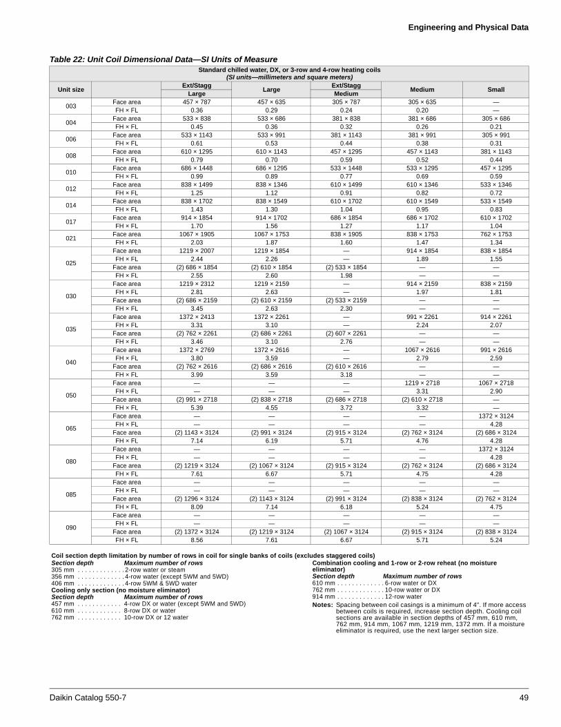
Engineering and Physical Data
Table 22: Unit Coil Dimensional Data—SI Units of MeasureStandard chilled water, DX, or 3-row and 4-row heating coils
(SI units—millimeters and square meters)
Unit sizeExt/Stagg
LargeExt/Stagg
Medium SmallLarge Medium
003Face area 457 × 787 457 × 635 305 × 787 305 × 635 —FH × FL 0.36 0.29 0.24 0.20 —
004Face area 533 × 838 533 × 686 381 × 838 381 × 686 305 × 686FH × FL 0.45 0.36 0.32 0.26 0.21
006Face area 533 × 1143 533 × 991 381 × 1143 381 × 991 305 × 991FH × FL 0.61 0.53 0.44 0.38 0.31
008Face area 610 × 1295 610 × 1143 457 × 1295 457 × 1143 381 × 1143FH × FL 0.79 0.70 0.59 0.52 0.44
010Face area 686 × 1448 686 × 1295 533 × 1448 533 × 1295 457 × 1295FH × FL 0.99 0.89 0.77 0.69 0.59
012Face area 838 × 1499 838 × 1346 610 × 1499 610 × 1346 533 × 1346FH × FL 1.25 1.12 0.91 0.82 0.72
014Face area 838 × 1702 838 × 1549 610 × 1702 610 × 1549 533 × 1549FH × FL 1.43 1.30 1.04 0.95 0.83
017Face area 914 × 1854 914 × 1702 686 × 1854 686 × 1702 610 × 1702FH × FL 1.70 1.56 1.27 1.17 1.04
021Face area 1067 × 1905 1067 × 1753 838 × 1905 838 × 1753 762 × 1753FH × FL 2.03 1.87 1.60 1.47 1.34
025
Face area 1219 × 2007 1219 × 1854 — 914 × 1854 838 × 1854FH × FL 2.44 2.26 — 1.89 1.55
Face area (2) 686 × 1854 (2) 610 × 1854 (2) 533 × 1854 — —FH × FL 2.55 2.60 1.98 — —
030
Face area 1219 × 2312 1219 × 2159 — 914 × 2159 838 × 2159FH × FL 2.81 2.63 — 1.97 1.81
Face area (2) 686 × 2159 (2) 610 × 2159 (2) 533 × 2159 — —FH × FL 3.45 2.63 2.30 — —
035
Face area 1372 × 2413 1372 × 2261 — 991 × 2261 914 × 2261FH × FL 3.31 3.10 — 2.24 2.07
Face area (2) 762 × 2261 (2) 686 × 2261 (2) 607 × 2261 — —FH × FL 3.46 3.10 2.76 — —
040
Face area 1372 × 2769 1372 × 2616 — 1067 × 2616 991 × 2616FH × FL 3.80 3.59 — 2.79 2.59
Face area (2) 762 × 2616 (2) 686 × 2616 (2) 610 × 2616 — —FH × FL 3.99 3.59 3.18 — —
050
Face area — — — 1219 × 2718 1067 × 2718FH × FL — — — 3.31 2.90
Face area (2) 991 × 2718 (2) 838 × 2718 (2) 686 × 2718 (2) 610 × 2718 —FH × FL 5.39 4.55 3.72 3.32 —
065
Face area — — — — 1372 × 3124FH × FL — — — — 4.28
Face area (2) 1143 × 3124 (2) 991 × 3124 (2) 915 × 3124 (2) 762 × 3124 (2) 686 × 3124FH × FL 7.14 6.19 5.71 4.76 4.28
080
Face area — — — — 1372 × 3124FH × FL — — — — 4.28
Face area (2) 1219 × 3124 (2) 1067 × 3124 (2) 915 × 3124 (2) 762 × 3124 (2) 686 × 3124FH × FL 7.61 6.67 5.71 4.75 4.28
085
Face area — — — — —FH × FL — — — — —
Face area (2) 1296 × 3124 (2) 1143 × 3124 (2) 991 × 3124 (2) 838 × 3124 (2) 762 × 3124FH × FL 8.09 7.14 6.18 5.24 4.75
090
Face area — — — — —FH × FL — — — — —
Face area (2) 1372 × 3124 (2) 1219 × 3124 (2) 1067 × 3124 (2) 915 × 3124 (2) 838 × 3124FH × FL 8.56 7.61 6.67 5.71 5.24
Coil section depth limitation by number of rows in coil for single banks of coils (excludes staggered coils)Section depth Maximum number of rows305 mm . . . . . . . . . . . . . 2-row water or steam356 mm . . . . . . . . . . . . . 4-row water (except 5WM and 5WD)406 mm . . . . . . . . . . . . . 4-row 5WM & 5WD waterCooling only section (no moisture eliminator)Section depth Maximum number of rows457 mm . . . . . . . . . . . . 4-row DX or water (except 5WM and 5WD)610 mm . . . . . . . . . . . . 8-row DX or water762 mm . . . . . . . . . . . . 10-row DX or 12 water
Combination cooling and 1-row or 2-row reheat (no moisture eliminator)Section depth Maximum number of rows610 mm . . . . . . . . . . . . . 6-row water or DX762 mm . . . . . . . . . . . . . 10-row water or DX914 mm . . . . . . . . . . . . . 12-row waterNotes: Spacing between coil casings is a minimum of 4". If more access
between coils is required, increase section depth. Cooling coil sections are available in section depths of 457 mm, 610 mm, 762 mm, 914 mm, 1067 mm, 1219 mm, 1372 mm. If a moisture eliminator is required, use the next larger section size.
Daikin Catalog 550-7 49

Engineering and Physical Data
Cleanable coils or 1-row and 2-row heating coils(SI units—millimeters and square meters)
Unit sizeExt/Stagg
LargeExt/Stagg
Medium SmallLarge Medium
003FH × FL 457 × 711 457 × 559 305 × 711 305 × 559 —
Face area 0.33 0.26 0.21 0.17 —
004FH × FL 533 × 762 533 × 610 381 × 762 381 × 610 305 × 610
Face area 0.41 0.33 0.29 0.23 0.19
006FH × FL 533 × 1067 533 × 914 381 × 1067 381 × 914 305 × 914
Face area 0.57 0.49 0.41 0.35 0.28
008FH × FL 610 × 1219 610 × 1067 457 × 1219 457 × 1067 381 × 1067
Face area 0.74 0.65 0.56 0.49 0.41
010FH × FL 686 × 1372 686 × 1219 533 × 1372 533 × 1219 457 × 1219
Face area 0.94 0.84 0.73 0.65 0.56
012FH × FL 838 × 1422 838 × 1270 610 × 1422 610 × 1270 533 × 1270
Face area 1.19 1.07 0.86 0.77 0.68
014FH × FL 838 × 1626 838 × 1473 610 × 1626 610 × 1473 533 × 1473
Face area 1.37 1.24 0.99 0.90 0.79
017FH × FL 914 × 1778 914 × 1626 686 × 1854 686 × 1626 610 × 1676
Face area 1.63 1.49 1.22 1.11 0.99
021FH × FL 1067 × 1829 1067 × 1676 838 × 1829 838 × 1676 762 × 1676
Face area 1.95 1.79 1.53 1.40 1.28
025
FH × FL — — 1067 × 1778 914 × 1778 838 × 1778Face area — — 1.89 1.63 1.49FH × FL (2) 686 × 1778 (2) 610 × 1778 — — —
Face area 2.43 2.16 — — —
030
FH × FL — — 1067× 2083 914 × 2083 838 × 2083Face area — — 2.22 1.90 1.75FH × FL (2) 686 × 2083 (2) 610 × 2083 — — —
Face area 2.86 2.54 — — —
035
FH × FL — — — 1067 × 2184 991 × 2184Face area — — — 2.33 2.16FH × FL (2) 762 × 2184 (2) 686 × 2184 (2) 610 × 2184 — —
Face area 3.33 3.00 2.66 — —
040
FH × FL — — — — 1067 × 2642Face area — — — — 2.81FH × FL (2) 762 × 2540 (2) 686 × 2540 (2) 610 × 2540 — —
Face area 3.87 3.48 3.09 — —
050
FH × FL — — — — 1067 × 2642Face area — — — — 2.81FH × FL (2) 991 × 2642 (2) 838 × 2642 (2) 686 × 2642 (2) 610 × 2642 —
Face area 5.23 4.43 3.62 3.22 —
065
FH × FL — — — — —Face area — — — — —FH × FL — (2) 991 × 3048 (2) 915 × 3048 (2) 762 × 3048 (2) 686 × 3048
Face area — 6.04 5.57 4.65 4.18
080
FH × FL — — — — —Face area — — — — —FH × FL — (2) 1067 × 3048 (2) 915 × 3048 (2) 762 × 3048 (2) 686 × 3048
Face area — 6.50 5.57 4.64 4.18
085
FH × FL — — — — —Face area — — — — —FH × FL — — (2) 991 × 3048 (2) 838 × 3048 (2) 762 × 3048
Face area — — 6.04 5.11 4.64
090
FH × FL — — — — —Face area — — — — —FH × FL — — (2) 1067 × 3048 (2) 915 × 3048 (2) 838 × 3048
Face area — — 6.50 5.57 5.11
Coil section depth limitation by number of rows in coil for single banks of coils (excludes staggered coils)Section depth Maximum number of rows305 mm . . . . . . . . . . . . . 2-row water or steam356 mm . . . . . . . . . . . . . 4-row water (except 5WM and 5WD)406 mm . . . . . . . . . . . . . 4-row 5WM & 5WD waterCooling only section (no moisture eliminator)Section depth Maximum number of rows457 mm . . . . . . . . . . . . . 4-row DX or water (except 5WM and 5WD)610 mm . . . . . . . . . . . . . 8-row DX or water762 mm . . . . . . . . . . . . . 10-row DX or 12 water
Combination cooling and 1-row or 2-row reheat (no moisture eliminator)Section depth Maximum number of rows610 mm . . . . . . . . . . . . 6-row water or DX762 mm . . . . . . . . . . . . 10-row water or DX914 mm . . . . . . . . . . . . 12-row waterNotes: Spacing between coil casings is a minimum of 4". If more access
between coils is required, increase section depth. Cooling coil sections are available in section depths of 457 mm, 610 mm, 762 mm, 914 mm, 1067 mm, 1219 mm, 1372 mm. If a moisture eliminator is required, use the next larger section size.
Table 22: Unit Coil Dimensional Data—SI Units of Measure (continued)
50 Daikin Catalog 550-7

Engineering and Physical Data
Multizone Coils
The face area of the multizone cold deck coil is the same as other cooling coils shown in Table 21 on page 48 and Table 22 on page 49. Multizone hot deck coils have a face area that is different from other heating coils. The face area for the multizone hot deck is generally smaller.
The minimum section depth for multizone sections is shown starting on page 70. Additional access is available downstream from the cooling coil. Refer to Vision SelectTools Software for more detailed information.
Table 23: Multizone Coils, English Units
Multizone hot deck coils(English units—inches and square feet)
Unit size 1-row & 2-row 3-row & 4-row
006FH × FL 12 × 36 12 × 39
Face area 3 3.3
008FH × FL 15 × 42 15 × 45
Face area 4.4 4.7
010FH × FL 15 × 48 15 × 51
Face area 5 5.3
012FH × FL 18 × 50 18 × 53
Face area 6.3 6.6
014FH × FL 18 × 58 18 × 61
Face area 7.3 7.6
017FH × FL 21 × 64 21 × 67
Face area 9.3 9.8
021FH × FL 24 × 66 24 × 69
Face area 11 11.5
025FH × FL 27 × 70 27 × 73
Face area 13.1 13.7
030FH × FL 27 × 82 27 × 85
Face area 15.4 15.9
035FH × FL 30 × 86 30 × 89
Face area 17.9 18.5
040FH × FL 30 × 100 30 × 103
Face area 20.8 21.5
050FH × FL 36 × 104 36 × 107
Face area 26 26.8
065FH × FL 42 × 120 42 × 123
Face area 35 35.9
080FH × FL N/A N/A
Face area N/A N/A
085FH × FL N/A N/A
Face area N/A N/A
090FH × FL N/A N/A
Face area N/A N/A
Table 24: Multizone Coils, SI Units
Multizone hot deck coils(SI unit—millimeters and square meters)
Unit size 1-row & 2-row 3-row & 4-row
006FH × FL 305 × 914 305 × 991
Face area 0.28 0.31
008FH × FL 381 × 1067 381 × 1143
Face area 0.41 0.44
010FH × FL 381 × 1219 381 × 1295
Face area 0.46 0.49
012FH × FL 457 × 1270 457 × 1346
Face area 0.59 0.61
014FH × FL 457 × 1473 457 ×1549
Face area 0.68 0.71
017FH × FL 533 × 1626 533 × 1702
Face area 0.86 0.91
021FH × FL 610 × 1676 610 × 1753
Face area 1.02 1.07
025FH × FL 686 × 1778 686 × 1854
Face area 1.22 1.27
030FH × FL 686 × 2083 686 × 2159
Face area 1.43 1.48
035FH × FL 762 × 2184 762 × 2261
Face area 1.66 1.72
040FH × FL 762 × 2540 762 × 2616
Face area 1.93 2
050FH × FL 914 × 2642 914 × 2718
Face area 2.42 2.49
065FH × FL 1067 × 3048 1067 × 3124
Face area 3.25 3.34
080FH × FL N/A N/A
Face area N/A N/A
085FH × FL N/A N/A
Face area N/A N/A
090
FH × FL N/A N/A
Face areaN/A
N/A
Daikin Catalog 550-7 51

Engineering and Physical Data
Side Load Filter Data
Table 25: Size and Quantity of Filters Used Per Unit Size
Unit size
Filter size (inches)
Number of filters used per filter section
2" t
hro
waw
ay(T
A)
2" a
ng
ula
r
4" a
ng
ula
r
12"
cart
rid
ge
4" c
artr
idg
e
12"
min
i ple
at
Bag
003
12 × 24 2
20 × 20
20 × 24 2
24 × 12 N/A
24 × 20 1 1 1 1 1
24 × 24
004
12 × 24 1 2 1 1 1 1
20 × 20
20 × 24
24 × 12 N/A
24 × 20
24 × 24 1 2 1 1 1 1
006
12 × 24
20 × 20
20 × 24
24 × 12 N/A
24 × 20
24 × 24 2 4 2 2 2 2
008
12 × 24 1 2 2 1 1 1 1
20 × 20
20 × 24 1 2 2 2 2 2 2
24 × 12
24 × 20
24 × 24 1 2 2
010
12 × 24 1
20 × 20
20 × 24 3 6 6 3 3 3
24 × 12
24 × 20
24 × 24 2
012
12 × 24 1 1 1 1 1
20 × 20
20 × 24 4 4
24 × 12 2 2 2 2 2
24 × 20
24 × 24 2 2 2 2 2 2 2
014
12 × 24
20 × 20
20 × 24 1 1 1 1
24 × 12 3 2 2 2 2
24 × 20
24 × 24 3 6 6 2 2 2 2
017
12 × 24 3 3
20 × 20
20 × 24 6 6
24 × 12
24 × 20 6 6 6 6 6
24 × 24 3 3
021
12 × 24
20 × 20 4 4 4 4
20 × 24 4 12 12 4 4 4
24 × 12
24 × 20 3
24 × 24 3
025
12 × 24 2 2 2 2
20 × 20
20 × 24 6 9 9
24 × 12
24 × 20
24 × 24 2 3 3 6 6 6 6
030
12 × 24
20 × 20
20 × 24
24 × 12 4 4 4 4 4
24 × 20 8 8 8 8 8
24 × 24 12 12
035
12 × 24
20 × 20 15 15 15 15
20 × 24 20 20
24 × 12
24 × 20 12
24 × 24
040
12 × 24 4 4 2
20 × 20 6 6 6 6
20 × 24 16 16
24 × 12 4
24 × 20 9 9 9 9
24 × 24 4 4 8
050
12 × 24
20 × 20
20 × 24 3 24 24 3 3 3 3
24 × 12
24 × 20
24 × 24 12 12 12 12 12
Table 25: Size and Quantity of Filters Used Per Unit Size
Unit size
Filter size (inches)
Number of filters used per filter section
2" t
hro
waw
ay(T
A)
2" a
ng
ula
r
4" a
ng
ula
r
12"
cart
rid
ge
4" c
artr
idg
e
12"
min
i ple
at
Bag
52 Daikin Catalog 550-7

Engineering and Physical Data
Note: Number of filters used per flat panel, 2" angular, and 4" angular filter section is based on pleated (30%).
065
12 × 24 3 3
20 × 20 9 9 9
20 × 24 3 10 10 3 3
24 × 12 5 5
24 × 20 9 9 9
24 × 24 3 20 20 15 3 15 3
080
12 × 24 3 3
20 × 20 3 3 3
20 × 24 9 10 10 9 9
24 × 12
24 × 20 3 5 3 5 3
24 × 24 9 20 20 15 9 15 9
Table 25: Size and Quantity of Filters Used Per Unit Size
Unit size
Filter size (inches)
Number of filters used per filter section
2"
thro
wa
wa
y(T
A)
2" a
ng
ula
r
4" a
ng
ula
r
12"
cart
rid
ge
4" c
artr
idg
e
12"
min
i ple
at
Bag
085
12 × 24 4 4 4 4 4 4
20 × 20
20 × 24 12 12 12
24 × 12
24 × 20
24 × 24 4 24 24 20 20 20 20
090
12 × 24 3
20 × 20 12 15 12 12
20 × 24 3 12 12 3 3
24 × 12 5
24 × 20 12 15 12 5 12
24 × 24 3 24 24 3 15 3
Table 25: Size and Quantity of Filters Used Per Unit Size
Unit size
Filter size (inches)
Number of filters used per filter section
2"
thro
wa
wa
y(T
A)
2" a
ng
ula
r
4" a
ng
ula
r
12"
cart
rid
ge
4" c
artr
idg
e
12"
min
i ple
at
Bag
Daikin Catalog 550-7 53
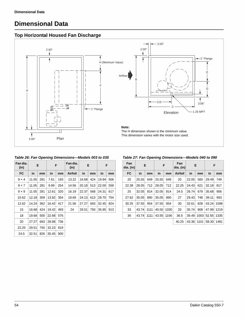
Dimensional Data
Dimensional Data
Top Horizontal Housed Fan Discharge
2.00"
3.00"
1" Flange
Airflow
2.00"
2.00"
1" Flange
Plan
Elevation 1.25 MPT
3.06"
A
H (Minimum Value)
F
C/2
C
G
E
B
Note:The H dimension shown is the minimum value. This dimension varies with the motor size used.
Table 26: Fan Opening Dimensions—Models 003 to 035
Fan dia. (in)
E FFan dia.
(in)E F
FC in mm in mm Airfoil in mm in mm
9 × 4 11.05 281 7.61 193 13.22 16.68 424 19.94 506
9 × 7 11.05 281 9.99 254 14.56 20.18 513 22.00 559
9 × 9 11.05 281 12.61 320 16.19 22.37 568 24.31 617
10.62 12.18 309 13.92 354 19.69 24.13 613 29.70 754
12.62 14.24 362 16.42 417 21.56 27.27 693 32.45 824
15 16.68 424 19.42 493 24 29.51 750 35.95 913
18 19.68 500 22.68 576
20 27.27 693 28.98 736
22.25 29.51 750 32.23 819
24.5 32.51 826 35.45 900
Table 27: Fan Opening Dimensions—Models 040 to 090
Fan dia. (in)
E FFan
dia. (in)E F
FC in mm in mm Airfoil in mm in mm
20 25.55 649 25.55 649 20 22.05 560 29.49 749
22.38 28.05 712 28.05 712 22.25 24.43 621 32.18 817
25 32.05 814 32.05 814 24.5 26.74 679 35.68 906
27.62 35.05 890 35.05 890 27 29.43 748 39.11 993
30.25 37.55 954 37.55 954 30 32.61 828 43.24 1098
33 43.74 1111 40.55 1030 33 35.74 908 47.99 1219
36 43.74 1111 43.55 1106 36.5 39.49 1003 52.55 1335
40.25 43.36 1101 58.30 1481
54 Daikin Catalog 550-7

Dimensional Data
* Not available with vanes.** These are the dimensions of the unit only. A standard base rail adds 8" (203 mm) to the width, and between 4" to 12" (102 mm to 305 mm) to the unit height.
A 6" (152 mm) base rail is mandatory on unit sizes 025-065. An 8" (203 mm) base rail is mandatory on unit sizes 080 and larger.
Table 28: Top Horizontal Housed Fan Dimensions
Unit size (fan diameter)A** B** C G H (min)
in mm in mm in mm in mm in mm
003 (9 × 4,9 × 7 FC)* 38.00 965 26.00 660 32.00 813 9.93 252 8.18 208
004 (9 × 9 FC)* 40.00 1016 30.00 762 32.00 813 9.93 252 8.18 208
006 (9 × 7, 9 × 9 FC)* 52.00 1321 30.00 762 32.00 813 9.93 252 8.18 208
006 (10.62 FC)* 52.00 1321 30.00 762 36.00 914 12.74 324 9.43 240
008 (12.62 FC) 58.00 1473 34.00 864 40.00 1016 14.61 371 10.83 275
008 (13.22 AF) 58.00 1473 34.00 864 40.00 1016 13.88 353 11.25 286
010 (15 FC) 64.00 1626 36.00 914 42.00 1067 15.55 395 12.50 318
010 (13.22 AF) 64.00 1626 36.00 914 40.00 1016 13.88 353 11.25 286
012 (18 FC) 66.00 1676 42.00 1067 46.00 1168 16.80 427 14.62 371
012 (16.19 AF) 66.00 1676 42.00 1067 46.00 1168 14.28 363 13.33 339
014 (18 FC) 74.00 1880 42.00 1067 46.00 1168 16.80 427 14.62 371
014 (16.19 AF) 74.00 1880 42.00 1118 46.00 1168 14.28 363 13.33 339
017 (18 FC) 80.00 2032 46.00 1168 46.00 1168 16.80 427 14.62 371
017 (19.69 AF) 80.00 2032 46.00 1168 50.00 1270 16.09 409 15.78 401
021 (20 FC) 82.00 2083 52.00 1321 52.00 1321 15.82 402 16.00 406
021 (21.56 AF) 82.00 2083 52.00 1321 52.00 1321 16.06 408 17.09 434
025 (24.50 FC)* 86.00 2184 60.00 1524 60.00 1524 18.63 473 19.15 486
025 (24 AF) 86.00 2184 60.00 1524 58.00 1473 17.55 446 18.80 478
030 (24.50 FC) 98.00 2489 60.00 1524 60.00 1524 18.63 473 19.15 486
030 (24 AF) 98.00 2489 60.00 1524 58.00 1473 17.55 446 18.80 478
035 (24.50 FC) 102.00 2591 66.00 1676 60.00 1524 18.63 473 19.15 486
035 (24 AF) 102.00 2591 66.00 1676 58.00 1473 17.55 446 18.80 478
040 (27.62 FC) 116.00 2946 68.00 1727 74.00 1880 26.28 668 40.47 1028
040 (27 AF) 116.00 2946 68.00 1727 70.00 1778 33.10 841 38.45 977
050 (36 FC) 120.00 3048 80.00 2032 82.00 2083 25.90 658 36.22 971
050 (33 AF) 120.00 3048 80.00 2032 80.00 2032 38.15 969 30.00 863
065 (40.25 AF) 136.00 3454 92.00 2337 92.00 2337 43.65 1109 34.85 987
080 (40.25 AF) 136.00 3454 98.00 2489 92.00 2337 43.65 1109 34.85 987
085 (40.25 AF) 136.00 3454 104.00 2641 92.00 2337 43.65 1109 34.85 987
090 (40.25 AF) 136.00 3454 110.00 2794 92.00 2337 43.65 1109 34.85 987
Daikin Catalog 550-7 55

Dimensional Data
Bottom Horizontal Housed Fan Discharge
2.00"
3.00"
1" Flange
Plan
A
H (Minimum Value)
F
Airflow
2.00"
2.00"
1" Flange
Elevation 1.25 MPT
3.06"C/2
C
G
EB
2.00"
Note:The H dimension shown is the minimum value. This dimension varies with the motor size used.
Table 29: Fan Opening Dimensions—Models 003 to 035
Fan dia. (in)
E FFan dia.
(in)E F
FC in mm in mm Airfoil in mm in mm
9 × 4 11.05 281 7.61 193 13.22 16.68 424 19.94 506
9 × 7 11.05 281 9.99 254 14.56 20.18 513 22.00 559
9 × 9 11.05 281 12.61 320 16.19 22.37 568 24.31 617
10.62 12.18 309 13.92 354 19.69 24.13 613 29.70 754
12.62 14.24 362 16.42 417 21.56 27.27 693 32.45 824
15 16.68 424 19.42 493 24 29.51 750 35.95 913
18 19.68 500 22.68 576
20 27.27 693 28.98 736
22.25 29.51 750 32.23 819
24.5 32.51 826 35.45 900
Table 30: Fan Opening Dimensions—Models 040 to 090
Fan dia. (in)
E FFan dia.
(in)E F
FC in mm in mm Airfoil in mm in mm
20 25.55 649 25.55 649 20 22.05 560 29.49 749
22.38 28.05 712 28.05 712 22.25 24.43 621 32.18 817
25 32.05 814 32.05 814 24.5 26.74 679 35.68 906
27.62 35.05 890 35.05 890 27 29.43 748 39.11 993
30.25 37.55 954 37.55 954 30 32.61 828 43.24 1098
33 43.74 1111 40.55 1030 33 35.74 908 47.99 1219
36 43.74 1111 43.55 1106 36.5 39.49 1003 52.55 1335
40.25 43.36 1101 58.30 1481
56 Daikin Catalog 550-7

Dimensional Data
* Not available with vanes.** These are the dimensions of the unit only. A standard base rail adds 8" (203 mm) to the width, and between 4" to 12" (102 mm to 305 mm) to the unit height.
A 6" (152 mm) base rail is mandatory on unit sizes 025-065. An 8" (203 mm) base rail is mandatory on unit sizes 080 and larger.
Table 31: Bottom Horizontal Housed Fan Dimensions
Unit size (fan diameter)A** B** C G H (min)
in mm in mm in mm in mm in mm
003 (9 × 4,9 × 7 FC)* 38.00 965 26.00 660 32.00 813 6.43 163 8.18 208
004 (9 × 9 FC)* 40.00 1016 30.00 762 32.00 813 6.43 163 8.18 208
006 (9 × 7, 9 × 9 FC)* 52.00 1321 30.00 762 32.00 813 6.43 163 8.18 208
006 (10.62 FC)* 52.00 1321 30.00 762 36.00 914 8.50 216 9.43 240
008 (12.62 FC) 58.00 1473 34.00 864 40.00 1016 8.50 216 10.83 275
008 (13.22 AF) 58.00 1473 34.00 864 40.00 1016 8.50 216 11.25 286
010 (15 FC) 64.00 1626 36.00 914 42.00 1067 8.50 216 12.50 318
010 (13.22 AF) 64.00 1626 36.00 914 40.00 1016 8.50 216 11.25 286
012 (18 FC) 66.00 1676 42.00 1067 46.00 1168 8.50 216 14.62 371
012 (16.19 AF) 66.00 1676 42.00 1067 46.00 1168 8.50 216 13.33 339
014 (18 FC) 74.00 1880 42.00 1067 46.00 1168 8.50 216 14.62 371
014 (16.19 AF) 74.00 1880 42.00 1118 46.00 1168 8.50 216 13.33 339
017 (18 FC) 80.00 2032 46.00 1168 46.00 1168 8.50 216 14.62 371
017 (19.69 AF) 80.00 2032 46.00 1168 50.00 1270 8.50 216 15.78 401
021 (20 FC) 82.00 2083 52.00 1321 52.00 1321 8.50 216 16.00 406
021 (21.56 AF) 82.00 2083 52.00 1321 52.00 1321 8.50 216 17.09 434
025 (24.50 FC)* 86.00 2184 60.00 1524 60.00 1524 8.50 216 19.15 486
025 (24 AF) 86.00 2184 60.00 1524 58.00 1473 8.50 216 18.80 478
030 (24.50 FC) 98.00 2489 60.00 1524 60.00 1524 8.50 216 19.15 486
030 (24 AF) 98.00 2489 60.00 1524 58.00 1473 8.50 216 18.80 478
035 (24.50 FC) 102.00 2591 66.00 1676 60.00 1524 8.50 216 19.15 486
035 (24 AF) 102.00 2591 66.00 1676 58.00 1473 8.50 216 18.80 478
040 (27.62 FC) 116.00 2946 90.00 2286 74.00 1880 13.03 331 40.47 1028
040 (27 AF) 116.00 2946 90.00 2286 70.00 1778 13.47 342 38.45 977
050 (36 FC) 120.00 3048 80.00 2032 82.00 2083 13.09 333 36.22 971
050 (33 AF) 120.00 3048 80.00 2032 80.00 2032 14.21 361 30.00 863
065 (40.25 AF) 136.00 3454 92.00 2337 92.00 2337 14.09 358 34.85 987
080 (40.25 AF) 136.00 3454 98.00 2489 92.00 2337 14.09 358 34.85 987
085 (40.25 AF) 136.00 3454 104.00 2641 92.00 2337 14.09 358 34.85 987
090 (40.25 AF) 136.00 3454 110.00 2794 92.00 2337 14.09 358 34.85 987
Daikin Catalog 550-7 57

Dimensional Data
Upblast Housed Fan Discharge
Airflow
Elevation 1.25 MPT
3.06"C/2
C
1" Flange
G
2.00"
B
2.00"
3.00"
1" Flange
Plan
A
H (Minimum Value)
F
Note:The H dimension shown is the minimum value. This dimension varies with the motor size used.
Table 32: Fan Opening Dimensions—Models 003 to 035
Fan dia. (in)
E FFan dia. (in)
E F
FC in mm in mm Airfoil in mm in mm
9 × 4 11.05 281 7.61 193 13.22 16.68 424 19.94 506
9 × 7 11.05 281 9.99 254 14.56 20.18 513 22.00 559
9 × 9 11.05 281 12.61 320 16.19 22.37 568 24.31 617
10.62 12.18 309 13.92 354 19.69 24.13 613 29.70 754
12.62 14.24 362 16.42 417 21.56 27.27 693 32.45 824
15 16.68 424 19.42 493 24 29.51 750 35.95 913
18 19.68 500 22.68 576
Table 33: Fan Opening Dimensions—Models 040 to 090
Fan dia. (in)
E FFan
dia. (in)E F
FC in mm in mm Airfoil in mm in mm
20 25.55 649 25.55 649 20 22.05 560 29.49 749
22.38 28.05 712 28.05 712 22.25 24.43 621 32.18 817
25 32.05 814 32.05 814 24.5 26.74 679 35.68 906
27.62 35.05 890 35.05 890 27 29.43 748 39.11 993
30.25 37.55 954 37.55 954 30 32.61 828 43.24 1098
33 43.74 1111 40.55 1030 33 35.74 908 47.99 1219
36 43.74 1111 43.55 1106 36.5 39.49 1003 52.55 1335
40.25 43.36 1101 58.30 1481
58 Daikin Catalog 550-7
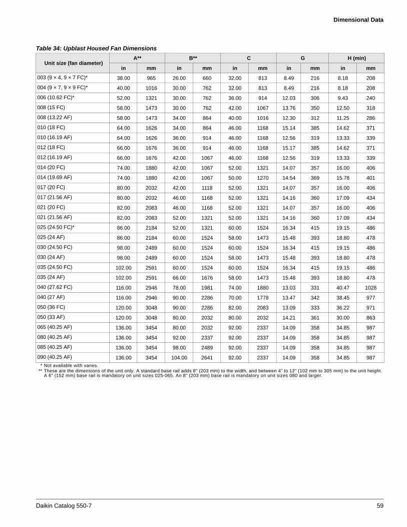
Dimensional Data
* Not available with vanes.** These are the dimensions of the unit only. A standard base rail adds 8" (203 mm) to the width, and between 4" to 12" (102 mm to 305 mm) to the unit height.
A 6" (152 mm) base rail is mandatory on unit sizes 025-065. An 8" (203 mm) base rail is mandatory on unit sizes 080 and larger.
Table 34: Upblast Housed Fan Dimensions
Unit size (fan diameter)A** B** C G H (min)
in mm in mm in mm in mm in mm
003 (9 × 4, 9 × 7 FC)* 38.00 965 26.00 660 32.00 813 8.49 216 8.18 208
004 (9 × 7, 9 × 9 FC)* 40.00 1016 30.00 762 32.00 813 8.49 216 8.18 208
006 (10.62 FC)* 52.00 1321 30.00 762 36.00 914 12.03 306 9.43 240
008 (15 FC) 58.00 1473 30.00 762 42.00 1067 13.76 350 12.50 318
008 (13.22 AF) 58.00 1473 34.00 864 40.00 1016 12.30 312 11.25 286
010 (18 FC) 64.00 1626 34.00 864 46.00 1168 15.14 385 14.62 371
010 (16.19 AF) 64.00 1626 36.00 914 46.00 1168 12.56 319 13.33 339
012 (18 FC) 66.00 1676 36.00 914 46.00 1168 15.17 385 14.62 371
012 (16.19 AF) 66.00 1676 42.00 1067 46.00 1168 12.56 319 13.33 339
014 (20 FC) 74.00 1880 42.00 1067 52.00 1321 14.07 357 16.00 406
014 (19.69 AF) 74.00 1880 42.00 1067 50.00 1270 14.54 369 15.78 401
017 (20 FC) 80.00 2032 42.00 1118 52.00 1321 14.07 357 16.00 406
017 (21.56 AF) 80.00 2032 46.00 1168 52.00 1321 14.16 360 17.09 434
021 (20 FC) 82.00 2083 46.00 1168 52.00 1321 14.07 357 16.00 406
021 (21.56 AF) 82.00 2083 52.00 1321 52.00 1321 14.16 360 17.09 434
025 (24.50 FC)* 86.00 2184 52.00 1321 60.00 1524 16.34 415 19.15 486
025 (24 AF) 86.00 2184 60.00 1524 58.00 1473 15.48 393 18.80 478
030 (24.50 FC) 98.00 2489 60.00 1524 60.00 1524 16.34 415 19.15 486
030 (24 AF) 98.00 2489 60.00 1524 58.00 1473 15.48 393 18.80 478
035 (24.50 FC) 102.00 2591 60.00 1524 60.00 1524 16.34 415 19.15 486
035 (24 AF) 102.00 2591 66.00 1676 58.00 1473 15.48 393 18.80 478
040 (27.62 FC) 116.00 2946 78.00 1981 74.00 1880 13.03 331 40.47 1028
040 (27 AF) 116.00 2946 90.00 2286 70.00 1778 13.47 342 38.45 977
050 (36 FC) 120.00 3048 90.00 2286 82.00 2083 13.09 333 36.22 971
050 (33 AF) 120.00 3048 80.00 2032 80.00 2032 14.21 361 30.00 863
065 (40.25 AF) 136.00 3454 80.00 2032 92.00 2337 14.09 358 34.85 987
080 (40.25 AF) 136.00 3454 92.00 2337 92.00 2337 14.09 358 34.85 987
085 (40.25 AF) 136.00 3454 98.00 2489 92.00 2337 14.09 358 34.85 987
090 (40.25 AF) 136.00 3454 104.00 2641 92.00 2337 14.09 358 34.85 987
Daikin Catalog 550-7 59
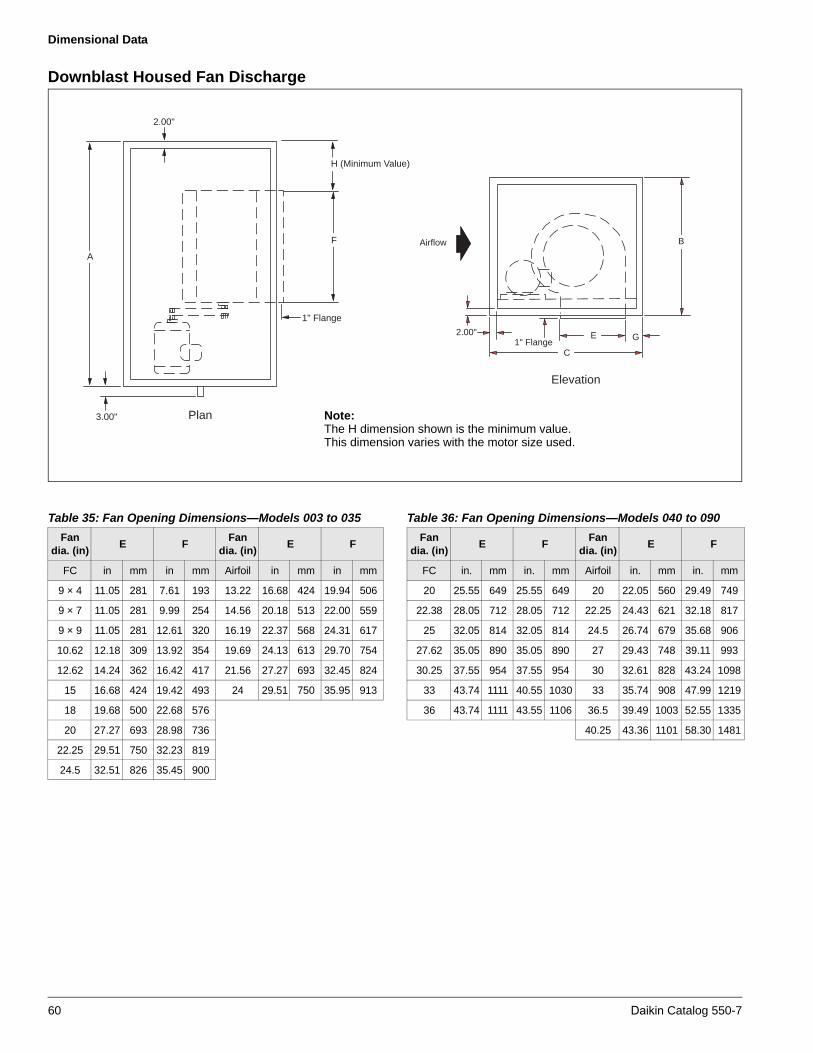
Dimensional Data
Downblast Housed Fan Discharge
Airflow
1" Flange
Elevation
C
E G2.00"
B
2.00"
3.00"
1" Flange
Plan
A
H (Minimum Value)
F
Note:The H dimension shown is the minimum value. This dimension varies with the motor size used.
Table 35: Fan Opening Dimensions—Models 003 to 035
Fan dia. (in)
E FFan
dia. (in)E F
FC in mm in mm Airfoil in mm in mm
9 × 4 11.05 281 7.61 193 13.22 16.68 424 19.94 506
9 × 7 11.05 281 9.99 254 14.56 20.18 513 22.00 559
9 × 9 11.05 281 12.61 320 16.19 22.37 568 24.31 617
10.62 12.18 309 13.92 354 19.69 24.13 613 29.70 754
12.62 14.24 362 16.42 417 21.56 27.27 693 32.45 824
15 16.68 424 19.42 493 24 29.51 750 35.95 913
18 19.68 500 22.68 576
20 27.27 693 28.98 736
22.25 29.51 750 32.23 819
24.5 32.51 826 35.45 900
Table 36: Fan Opening Dimensions—Models 040 to 090
Fan dia. (in)
E FFan
dia. (in)E F
FC in. mm in. mm Airfoil in. mm in. mm
20 25.55 649 25.55 649 20 22.05 560 29.49 749
22.38 28.05 712 28.05 712 22.25 24.43 621 32.18 817
25 32.05 814 32.05 814 24.5 26.74 679 35.68 906
27.62 35.05 890 35.05 890 27 29.43 748 39.11 993
30.25 37.55 954 37.55 954 30 32.61 828 43.24 1098
33 43.74 1111 40.55 1030 33 35.74 908 47.99 1219
36 43.74 1111 43.55 1106 36.5 39.49 1003 52.55 1335
40.25 43.36 1101 58.30 1481
60 Daikin Catalog 550-7

Dimensional Data
* Not available with vanes.** These are the dimensions of the unit only. A base rail adds 8" (203 mm) to the width, and between 4" to 12" (102 mm to 305 mm) to the unit height.
A 6" (152 mm) base rail is mandatory on unit sizes 025 to 065. An 8" (203 mm) base rail is mandatory on unit sizes 080 and larger.
Table 37: Downblast Housed Fan Dimensions
Unit size (fan diameter)
A** B** C G H (min)
in mm in mm in mm in mm in mm
003 (9 × 4,9 × 7 FC)* 38.00 965 26.00 660 36.00 914 6.43 163 8.18 208
004 (9 × 7,9 × 9 FC)* 40.00 1016 30.00 762 36.00 914 6.43 163 8.18 208
006 (10.62 FC)* 52.00 1321 30.00 762 40.00 1016 8.50 216 9.43 240
008 (15 FC) 58.00 1473 34.00 864 46.00 1168 8.50 216 12.50 318
008 (13.22 AF) 58.00 1473 34.00 864 44.00 1118 8.50 216 11.25 286
010 (15FC) 64.00 1626 36.00 914 46.00 1168 8.50 216 12.50 318
010 (14.56 AF) 64.00 1626 36.00 914 48.00 1219 8.50 216 12.19 310
012 (18 FC) 66.00 1676 42.00 1067 50.00 1270 8.50 216 14.62 371
012 (16.19 AF) 66.00 1676 42.00 1067 52.00 1321 8.50 216 13.33 339
014 (18 FC) 74.00 1880 42.00 1067 50.00 1270 8.50 216 14.62 371
014 (19.69 AF) 74.00 1880 42.00 1067 56.00 1422 8.50 216 15.78 401
017 (20 FC) 80.00 2032 46.00 1168 56.00 1422 8.50 216 16.00 406
017 (21.56 AF) 80.00 2032 46.00 1168 58.00 1473 8.50 216 17.09 434
021 (20 FC) 82.00 2083 52.00 1321 56.00 1422 8.50 216 16.00 406
021 (2156 AF) 82.00 2083 52.00 1321 58.00 1473 8.50 216 17.09 434
025 (24.50 FC)* 86.00 2184 60.00 1524 62.00 1575 8.50 216 19.15 486
025 (24 AF) 86.00 2184 60.00 1524 62.00 1575 8.50 216 18.80 478
030 (24.50 FC) 9800 2489 60.00 1524 62.00 1575 8.50 216 19.15 486
030 (24 AF) 98.00 2489 60.00 1524 62.00 1575 8.50 216 18.80 478
035 (24.50 FC) 102.00 2591 66.00 1676 62.00 1575 8.50 216 19.15 486
035 (24 AF) 102.00 2591 66.00 1676 62.00 1575 8.50 216 18.80 478
040 (27.62 FC) 116.00 2946 68.00 1727 74.00 1880 13.03 331 40.47 1028
040 (27 AF) 116.00 2921 68.00 1727 76.00 1930 13.47 342 38.45 977
050 (36 FC) 120.00 3048 80.00 2032 80.00 2032 13.09 333 36.22 971
050 (33 AF) 120.00 3048 80.00 2032 86.00 2184 14.21 361 30.00 863
065 (40.25 AF) 136.00 3454 92.00 2337 96.00 2438 14.09 358 34.85 987
080 (40.25 AF) 136.00 3454 98.00 2489 96.00 2438 12.6 320 34.85 987
085 (40.25 AF) 136.00 3454 104.00 2641 96.00 2438 12.6 320 34.85 987
090 (40.25 AF) 136.00 3454 110.00 2794 96.00 2438 12.6 320 34.85 987
Daikin Catalog 550-7 61
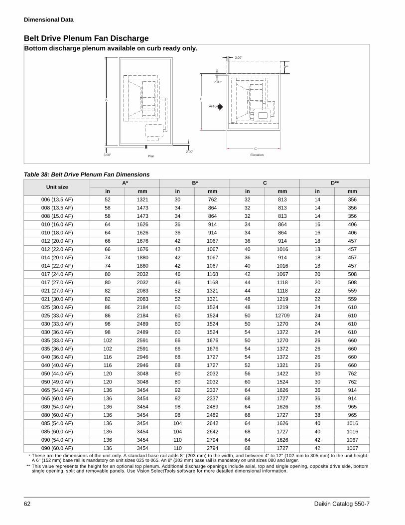
Dimensional Data
Belt Drive Plenum Fan Discharge
* These are the dimensions of the unit only. A standard base rail adds 8" (203 mm) to the width, and between 4" to 12" (102 mm to 305 mm) to the unit height.A 6" (152 mm) base rail is mandatory on unit sizes 025 to 065. An 8" (203 mm) base rail is mandatory on unit sizes 080 and larger.
** This value represents the height for an optional top plenum. Additional discharge openings include axial, top and single opening, opposite drive side, bottom single opening, split and removable panels. Use Vision SelectTools software for more detailed dimensional information.
B
2.00"
2.00"
Airflow
2.00"C
Elevation3.00" Plan
A
D**
Bottom discharge plenum available on curb ready only.
Table 38: Belt Drive Plenum Fan Dimensions
Unit sizeA* B* C D**
in mm in mm in mm in mm
006 (13.5 AF) 52 1321 30 762 32 813 14 356
008 (13.5 AF) 58 1473 34 864 32 813 14 356
008 (15.0 AF) 58 1473 34 864 32 813 14 356
010 (16.0 AF) 64 1626 36 914 34 864 16 406
010 (18.0 AF) 64 1626 36 914 34 864 16 406
012 (20.0 AF) 66 1676 42 1067 36 914 18 457
012 (22.0 AF) 66 1676 42 1067 40 1016 18 457
014 (20.0 AF) 74 1880 42 1067 36 914 18 457
014 (22.0 AF) 74 1880 42 1067 40 1016 18 457
017 (24.0 AF) 80 2032 46 1168 42 1067 20 508
017 (27.0 AF) 80 2032 46 1168 44 1118 20 508
021 (27.0 AF) 82 2083 52 1321 44 1118 22 559
021 (30.0 AF) 82 2083 52 1321 48 1219 22 559
025 (30.0 AF) 86 2184 60 1524 48 1219 24 610
025 (33.0 AF) 86 2184 60 1524 50 12709 24 610
030 (33.0 AF) 98 2489 60 1524 50 1270 24 610
030 (36.0 AF) 98 2489 60 1524 54 1372 24 610
035 (33.0 AF) 102 2591 66 1676 50 1270 26 660
035 (36.0 AF) 102 2591 66 1676 54 1372 26 660
040 (36.0 AF) 116 2946 68 1727 54 1372 26 660
040 (40.0 AF) 116 2946 68 1727 52 1321 26 660
050 (44.0 AF) 120 3048 80 2032 56 1422 30 762
050 (49.0 AF) 120 3048 80 2032 60 1524 30 762
065 (54.0 AF) 136 3454 92 2337 64 1626 36 914
065 (60.0 AF) 136 3454 92 2337 68 1727 36 914
080 (54.0 AF) 136 3454 98 2489 64 1626 38 965
080 (60.0 AF) 136 3454 98 2489 68 1727 38 965
085 (54.0 AF) 136 3454 104 2642 64 1626 40 1016
085 (60.0 AF) 136 3454 104 2642 68 1727 40 1016
090 (54.0 AF) 136 3454 110 2794 64 1626 42 1067
090 (60.0 AF) 136 3454 110 2794 68 1727 42 1067
62 Daikin Catalog 550-7

Dimensional Data
Fan Array
ALDL
H
FL
W
Four Fan Model
Table 39: Fan Array Dimensions
Fan Configuration Fan DiameterMinimum Unit
SizeAccess Length
(AL)Damper Length
(DL)Width
(W)Height
(H)
1 × 3
12 17 26 12 76 28
13 21 28 12 82 30
15 30 30 12 94 32
16 35 32 12 100 36
18 40 32 12 112 36
20 65 36 12 124 40
22 65 38 14 136 42
24 107 42 14 148 46
27 107 44 16 166 48
30 124 48 16 184 50
33 160 52 20 202 54
2 × 2
12 21 26 12 52 52
13 25 28 12 56 56
15 25 30 12 64 60
16 35 32 12 68 66
18 40 32 12 76 68
20 50 36 12 84 74
22 50 38 14 92 80
24 65 42 14 100 86
27 65 44 16 112 92
30 80 48 16 124 96
33 85 52 20 136 104
2 × 3
12 21 26 12 76 52
13 25 28 12 82 56
15 30 30 12 94 60
16 35 32 12 100 66
18 40 32 12 112 68
20 65 36 12 124 74
22 65 38 14 136 80
24 107 42 14 148 86
27 107 44 16 166 92
30 124 48 16 184 96
33 160 52 20 202 104
Daikin Catalog 550-7 63
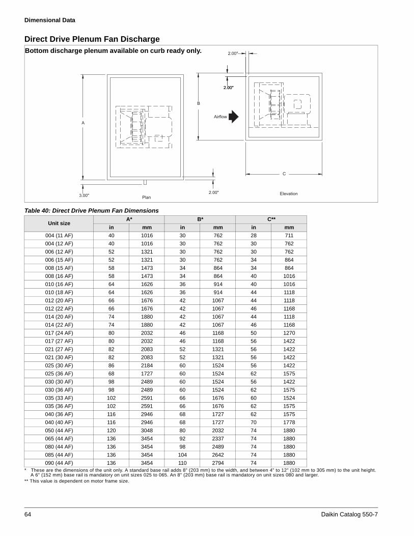
Dimensional Data
Direct Drive Plenum Fan Discharge
* These are the dimensions of the unit only. A standard base rail adds 8" (203 mm) to the width, and between 4" to 12" (102 mm to 305 mm) to the unit height.A 6" (152 mm) base rail is mandatory on unit sizes 025 to 065. An 8" (203 mm) base rail is mandatory on unit sizes 080 and larger.
** This value is dependent on motor frame size.
A
B
2.00"
2.00"
Airflow
2.00"
C
Elevation3.00" Plan
2.00"
Bottom discharge plenum available on curb ready only.
Table 40: Direct Drive Plenum Fan Dimensions
Unit sizeA* B* C**
in mm in mm in mm
004 (11 AF) 40 1016 30 762 28 711
004 (12 AF) 40 1016 30 762 30 762
006 (12 AF) 52 1321 30 762 30 762
006 (15 AF) 52 1321 30 762 34 864
008 (15 AF) 58 1473 34 864 34 864
008 (16 AF) 58 1473 34 864 40 1016
010 (16 AF) 64 1626 36 914 40 1016
010 (18 AF) 64 1626 36 914 44 1118
012 (20 AF) 66 1676 42 1067 44 1118
012 (22 AF) 66 1676 42 1067 46 1168
014 (20 AF) 74 1880 42 1067 44 1118
014 (22 AF) 74 1880 42 1067 46 1168
017 (24 AF) 80 2032 46 1168 50 1270
017 (27 AF) 80 2032 46 1168 56 1422
021 (27 AF) 82 2083 52 1321 56 1422
021 (30 AF) 82 2083 52 1321 56 1422
025 (30 AF) 86 2184 60 1524 56 1422
025 (36 AF) 68 1727 60 1524 62 1575
030 (30 AF) 98 2489 60 1524 56 1422
030 (36 AF) 98 2489 60 1524 62 1575
035 (33 AF) 102 2591 66 1676 60 1524
035 (36 AF) 102 2591 66 1676 62 1575
040 (36 AF) 116 2946 68 1727 62 1575
040 (40 AF) 116 2946 68 1727 70 1778
050 (44 AF) 120 3048 80 2032 74 1880
065 (44 AF) 136 3454 92 2337 74 1880
080 (44 AF) 136 3454 98 2489 74 1880
085 (44 AF) 136 3454 104 2642 74 1880
090 (44 AF) 136 3454 110 2794 74 1880
64 Daikin Catalog 550-7

Dimensional Data
Dual Direct Drive Plenum Fan Discharge
* These are the dimensions of the unit only. A standard base rail adds 8" (203 mm) to the width, and between 4" to 12" (102 mm to 305 mm) to the unit height.A 6" (152 mm) base rail is mandatory on unit sizes 025 to 065. An 8" (203 mm) base rail is mandatory on unit sizes 080 and larger.
** This value is dependent on motor frame size.
A
B
2.00"
2.00"
Airflow
2.00"
C
Elevation3.00" Plan
2.00"
Bottom discharge plenum available on curb ready only.
Table 41: Dual Direct Drive Plenum Fan Dimensions
Unit sizeA* B* C**
in mm in mm in mm
004 (11 AF) 80 2032 30 762 28 711
004 (12 AF) 80 2032 30 762 30 762
006 (12 AF) 104 2642 30 762 30 762
006 (15 AF) 104 2642 30 762 34 864
008 (15 AF) 116 2946 34 864 34 864
008 (16 AF) 116 2946 34 864 40 1016
010 (16 AF) 128 3251 36 914 40 1016
010 (18 AF) 128 3251 36 914 44 1118
012 (20 AF) 132 3353 42 1067 44 1118
012 (22 AF) 132 3353 42 1067 46 1168
014 (20 AF) 148 3759 42 1067 44 1118
014 (22 AF) 148 3759 42 1067 46 1168
017 (24 AF) 160 4064 46 1168 50 1270
017 (27 AF) 160 4064 46 1168 56 1422
021 (27 AF) 164 4166 52 1321 56 1422
021 (30 AF) 164 4166 52 1321 56 1422
025 (30 AF) 172 4369 60 1524 56 1422
025 (36 AF) 136 3454 60 1524 62 1575
030 (30 AF) 196 4978 60 1524 56 1422
030 (36 AF) 196 4978 60 1524 62 1575
035 (33 AF) 204 5182 66 1676 60 1524
035 (36 AF) 204 5182 66 1676 62 1575
040 (36 AF) 232 5893 68 1727 62 1575
040 (40 AF) 232 5893 68 1727 70 1778
050 (44 AF) 240 6096 80 2032 74 1880
065 (44 AF) 272 6909 92 2337 74 1880
080 (44 AF) 272 6909 98 2489 74 1880
085 (44 AF) 272 6909 104 2642 74 1880
090 (44 AF) 272 6909 110 2794 74 1880
Daikin Catalog 550-7 65
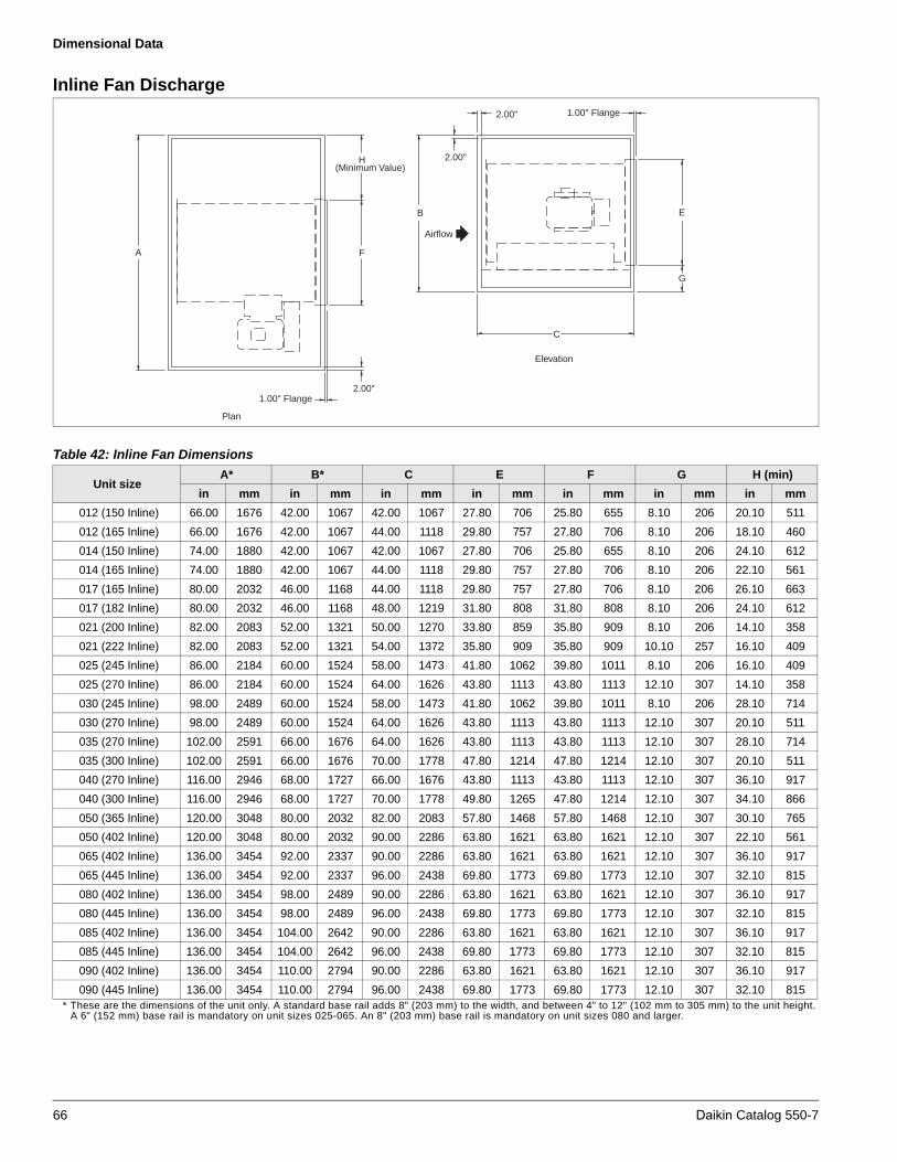
Dimensional Data
Inline Fan Discharge
* These are the dimensions of the unit only. A standard base rail adds 8" (203 mm) to the width, and between 4" to 12" (102 mm to 305 mm) to the unit height.A 6" (152 mm) base rail is mandatory on unit sizes 025-065. An 8" (203 mm) base rail is mandatory on unit sizes 080 and larger.
A
2.00"
2.00"
Airflow
2.00"
C
Elevation
1.00" Flange
Plan
E
G
1.00" Flange
H(Minimum Value)
F
B
Table 42: Inline Fan Dimensions
Unit size A* B* C E F G H (min)
in mm in mm in mm in mm in mm in mm in mm
012 (150 Inline) 66.00 1676 42.00 1067 42.00 1067 27.80 706 25.80 655 8.10 206 20.10 511
012 (165 Inline) 66.00 1676 42.00 1067 44.00 1118 29.80 757 27.80 706 8.10 206 18.10 460
014 (150 Inline) 74.00 1880 42.00 1067 42.00 1067 27.80 706 25.80 655 8.10 206 24.10 612
014 (165 Inline) 74.00 1880 42.00 1067 44.00 1118 29.80 757 27.80 706 8.10 206 22.10 561
017 (165 Inline) 80.00 2032 46.00 1168 44.00 1118 29.80 757 27.80 706 8.10 206 26.10 663
017 (182 Inline) 80.00 2032 46.00 1168 48.00 1219 31.80 808 31.80 808 8.10 206 24.10 612
021 (200 Inline) 82.00 2083 52.00 1321 50.00 1270 33.80 859 35.80 909 8.10 206 14.10 358
021 (222 Inline) 82.00 2083 52.00 1321 54.00 1372 35.80 909 35.80 909 10.10 257 16.10 409
025 (245 Inline) 86.00 2184 60.00 1524 58.00 1473 41.80 1062 39.80 1011 8.10 206 16.10 409
025 (270 Inline) 86.00 2184 60.00 1524 64.00 1626 43.80 1113 43.80 1113 12.10 307 14.10 358
030 (245 Inline) 98.00 2489 60.00 1524 58.00 1473 41.80 1062 39.80 1011 8.10 206 28.10 714
030 (270 Inline) 98.00 2489 60.00 1524 64.00 1626 43.80 1113 43.80 1113 12.10 307 20.10 511
035 (270 Inline) 102.00 2591 66.00 1676 64.00 1626 43.80 1113 43.80 1113 12.10 307 28.10 714
035 (300 Inline) 102.00 2591 66.00 1676 70.00 1778 47.80 1214 47.80 1214 12.10 307 20.10 511
040 (270 Inline) 116.00 2946 68.00 1727 66.00 1676 43.80 1113 43.80 1113 12.10 307 36.10 917
040 (300 Inline) 116.00 2946 68.00 1727 70.00 1778 49.80 1265 47.80 1214 12.10 307 34.10 866
050 (365 Inline) 120.00 3048 80.00 2032 82.00 2083 57.80 1468 57.80 1468 12.10 307 30.10 765
050 (402 Inline) 120.00 3048 80.00 2032 90.00 2286 63.80 1621 63.80 1621 12.10 307 22.10 561
065 (402 Inline) 136.00 3454 92.00 2337 90.00 2286 63.80 1621 63.80 1621 12.10 307 36.10 917
065 (445 Inline) 136.00 3454 92.00 2337 96.00 2438 69.80 1773 69.80 1773 12.10 307 32.10 815
080 (402 Inline) 136.00 3454 98.00 2489 90.00 2286 63.80 1621 63.80 1621 12.10 307 36.10 917
080 (445 Inline) 136.00 3454 98.00 2489 96.00 2438 69.80 1773 69.80 1773 12.10 307 32.10 815
085 (402 Inline) 136.00 3454 104.00 2642 90.00 2286 63.80 1621 63.80 1621 12.10 307 36.10 917
085 (445 Inline) 136.00 3454 104.00 2642 96.00 2438 69.80 1773 69.80 1773 12.10 307 32.10 815
090 (402 Inline) 136.00 3454 110.00 2794 90.00 2286 63.80 1621 63.80 1621 12.10 307 36.10 917
090 (445 Inline) 136.00 3454 110.00 2794 96.00 2438 69.80 1773 69.80 1773 12.10 307 32.10 815
66 Daikin Catalog 550-7

Dimensional Data
Cooling Coil Section
The single cooling coil section is available in numerous depths. This provides the option of varying the amount of space downstream from the coil for access to inspect and clean the coil and drain pan. When using a single bank of coils, the 18" deep section holds up to a 4-row water or DX coil.
Also available are staggered cooling coils. The staggered arrangement maximizes the cooling coil face area by providing two banks of coils. These two coils are not stacked, but are staggered in the direction of airflow. This configuration does require more section depth in the direction of airflow. Staggered coils are only available on unit sizes 025 and larger.
The section depth required varies between 30" to 54". This depends on the unit size and number of rows in the coil.
When a coil section is used in a vertical application, the section must be deep enough to support the fan above it and keep the face velocity through the top opening below 1000 fpm. The coil section should be a minimum of 36" deep in direction of airflow. As the fan and airflow get larger, it may be necessary to add a plenum downstream from the coil section. Drain connections for units with width A greater than 108", in Table 43 below, are 1.50 MPT.*
* These are the dimensions of the unit only. A standard base rail adds 8" (203 mm) to the width, and between 4" to 12" (102 mm to 305 mm) to the unit height. A 6" (152 mm) base rail is mandatory on unit sizes 025 to 065. An 8" (203 mm) base rail is mandatory on unit sizes 080 and larger.
** 18.0", 24.0", 30.0", 36.0", 42.0", 48.0", and 54.0" cooling coil sections available for all unit sizes.
Airflow
Plan
Elevation
2.00"
A
6.00" - 8.00"approx.
3.00"
2.00"
C
B
3.00" 2.00"
C/2 Drain Conn.*1.25 MPT
Table 43: Cooling Coil Dimensions
Unit sizeA (large, medium coils)* A (extended coils)* B* C (available all sizes)**
in. mm in. mm in. mm in. mm
003 38.00 965 44.00 1118 26.00 660 18.00 457
004 40.00 1016 46.00 1168 30.00 762 24.00 610
006 52.00 1321 58.00 1473 30.00 762 30.00 762
008 58.00 1473 64.00 1626 34.00 864 36.00 914
010 64.00 1626 70.00 1778 36.00 914 42.00 1067
012 66.00 1676 72.00 1829 42.00 1067 48.00 1219
014 74.00 1880 80.00 2032 42.00 1067 54.00 1372
017 80.00 2032 86.00 2184 46.00 1168 — —
021 82.00 2083 88.00 2235 52.00 1321 — —
025 86.00 2184 N/A N/A 60.00 1524 — —
030 98.00 2489 N/A N/A 60.00 1524 — —
035 102.00 2591 N/A N/A 66.00 1676 — —
040 116.00 2946 N/A N/A 68.00 1727 — —
050 120.00 3048 N/A N/A 80.00 2032 — —
065 136.00 3454 N/A N/A 92.00 2337 — —
080 136.00 3454 N/A N/A 98.00 2489 — —
085 136.00 3454 N/A N/A 104.00 2642 — —
090 136.00 3454 N/A N/A 110.00 2794 — —
Daikin Catalog 550-7 67

Dimensional Data
Combination Cooling and Reheat Coil Section
The combination cooling and reheat coil section is available in numerous depths. This provides the option of varying the amount of space between the cooling coil and reheat coil for access to inspect and clean the coil and drain pan. All reheat and most cooling coils are arranged in a single bank, which can be 1, 2 or 3 coils high. When using a single bank of cooling coils, the 24" deep section holds up to a 4-row water or DX coil, and a 1-row or 2-row heating coil. A 36" deep section holds a 12-row water coil and a 1 or 2-row reheat coil.
Also available are staggered cooling coils. The staggered arrangement maximizes the cooling coil face area by providing two banks of coils. These two coils are not stacked, but are
staggered in the direction of airflow. This configuration does require more section depth in the direction of airflow. Staggered coils are available only on unit sizes 025 and larger. The section depth required varies between 30" to 54". This depends on the unit size and number of rows in the coil.
When a combination coil section is used in a vertical application, a plenum must be provided on the leaving air side of the coil. The plenum is used for discharging air into the bottom of the fan section. Drain connections for units with width A greater than 108", in Table 44 below, are 1.50 MPT.*
* These are the dimensions of the unit only. A standard base rail adds 8" (203 mm) to the width, and between 4" to 12" (102 mm to 305 mm) to the unit height.A 6" (152 mm) base rail is mandatory on unit sizes 025-065. An 8" (203 mm) base rail is mandatory on unit sizes 080 and larger.
** 18.0", 24.0", 30.0", 36.0", 42.0", 48.0", and 54.0" cooling coil sections available for all unit sizes.
Airflow
Plan
Elevation
2.00"
A
6.00" - 8.00"approx.
3.00"
2.00"
C
B
3.00" 2.00"
C/2 Drain Conn.*1.25 MPT
Table 44: Combination Cooling and Reheat Coil Dimensions
Unit sizeA (large, medium coils)* A (extended coils)* B* C (available all sizes)**
in. mm in. mm in. mm in. mm
003 38.00 965 44.00 1118 26.00 660 24.00 610
004 40.00 1016 46.00 1168 30.00 762 30.00 762
006 52.00 1321 58.00 1473 30.00 762 36.00 914
008 58.00 1473 64.00 1626 34.00 864 42.00 1067
010 64.00 1626 70.00 1778 36.00 914 48.00 1219
012 66.00 1676 72.00 1829 42.00 1067 54.00 1372
014 74.00 1880 80.00 2032 42.00 1067 — —
017 80.00 2032 86.00 2184 46.00 1168 — —
021 82.00 2083 88.00 2235 52.00 1321 — —
025 86.00 2184 N/A N/A 60.00 1524 — —
030 98.00 2489 N/A N/A 60.00 1524 — —
035 102.00 2591 N/A N/A 66.00 1676 — —
040 116.00 2946 N/A N/A 68.00 1727 — —
050 120.00 3048 N/A N/A 80.00 2032 — —
065 136.00 3454 N/A N/A 92.00 2337 — —
080 136.00 3454 N/A N/A 98.00 2489 — —
085 136.00 3454 N/A N/A 104.00 2642 — —
090 136.00 3454 N/A N/A 110.00 2794 — —
68 Daikin Catalog 550-7

Dimensional Data
Heating Coil Section
Note: 1.25 MPT drain connections are available as an option for heating coil sections.
* These are the dimensions of the unit only. A standard base rail adds 8" (203 mm) to the width and between 4" to 12" (102 mm to 305 mm) to the unit height.A base rail is mandatory on unit sizes 025 to 065 and adds a minimum of 6" (152 mm) to the unit height. Unit sizes greater than 080 require a base rail thatadds a minimum of 8" (203 mm to 305 mm) to the unit height.
Table 45: Heating Coil Dimensions*
Unit sizeA B
in mm in mm
003 38.00 965 26.00 660
004 40.00 1016 30.00 762
006 52.00 1321 30.00 762
008 58.00 1473 34.00 864
010 64.00 1626 36.00 914
012 66.00 1676 42.00 1067
014 74.00 1880 42.00 1067
017 80.00 2032 46.00 1168
021 82.00 2083 52.00 1321
025 86.00 2184 60.00 1524
030 98.00 2489 60.00 1524
035 102.00 2591 66.00 1676
040 116.00 2946 68.00 1727
050 120.00 3048 80.00 2032
065 136.00 3454 92.00 2337
080 136.00 3454 98.00 2489
085 136.00 3454 104.00 2642
090 136.00 3454 110.00 2794
Plan
6.00" - 8.00"approx.2.00"
A Airflow
B
Elevation
12.00"
2.00"
2.00"
Airflow
B
Elevation
14.00"
2.00"
2.00"
Plan
6.00" - 8.00"approx.2.00"
A
3 and 4 row heating coil section(cased coils)
1 and 2 row heating coil section(uncased coils)
Daikin Catalog 550-7 69
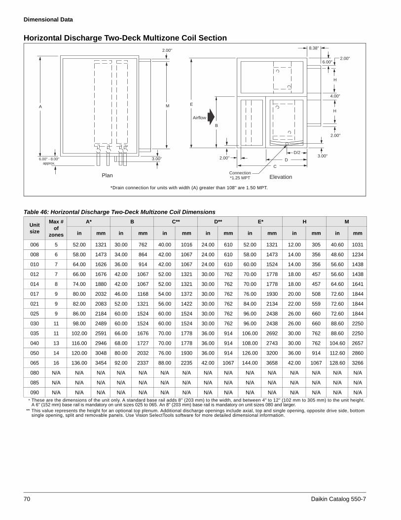
Dimensional Data
Horizontal Discharge Two-Deck Multizone Coil Section
* These are the dimensions of the unit only. A standard base rail adds 8" (203 mm) to the width, and between 4" to 12" (102 mm to 305 mm) to the unit height.A 6" (152 mm) base rail is mandatory on unit sizes 025 to 065. An 8" (203 mm) base rail is mandatory on unit sizes 080 and larger.
** This value represents the height for an optional top plenum. Additional discharge openings include axial, top and single opening, opposite drive side, bottom single opening, split and removable panels. Use Vision SelectTools software for more detailed dimensional information.
Plan
6.00" - 8.00"approx.
3.00"
A M
Airflow
Elevation
2.00"
2.00"
E
B
C
D
D/2
H
3.00"
4.00"
2.00"6.00"
8.38"
H
Connection*1.25 MPT
2.00"
*Drain connection for units with width (A) greater than 108" are 1.50 MPT.
Table 46: Horizontal Discharge Two-Deck Multizone Coil Dimensions
Unit size
Max # of
zones
A* B C** D** E* H M
in mm in mm in mm in mm in mm in mm in mm
006 5 52.00 1321 30.00 762 40.00 1016 24.00 610 52.00 1321 12.00 305 40.60 1031
008 6 58.00 1473 34.00 864 42.00 1067 24.00 610 58.00 1473 14.00 356 48.60 1234
010 7 64.00 1626 36.00 914 42.00 1067 24.00 610 60.00 1524 14.00 356 56.60 1438
012 7 66.00 1676 42.00 1067 52.00 1321 30.00 762 70.00 1778 18.00 457 56.60 1438
014 8 74.00 1880 42.00 1067 52.00 1321 30.00 762 70.00 1778 18.00 457 64.60 1641
017 9 80.00 2032 46.00 1168 54.00 1372 30.00 762 76.00 1930 20.00 508 72.60 1844
021 9 82.00 2083 52.00 1321 56.00 1422 30.00 762 84.00 2134 22.00 559 72.60 1844
025 9 86.00 2184 60.00 1524 60.00 1524 30.00 762 96.00 2438 26.00 660 72.60 1844
030 11 98.00 2489 60.00 1524 60.00 1524 30.00 762 96.00 2438 26.00 660 88.60 2250
035 11 102.00 2591 66.00 1676 70.00 1778 36.00 914 106.00 2692 30.00 762 88.60 2250
040 13 116.00 2946 68.00 1727 70.00 1778 36.00 914 108.00 2743 30.00 762 104.60 2657
050 14 120.00 3048 80.00 2032 76.00 1930 36.00 914 126.00 3200 36.00 914 112.60 2860
065 16 136.00 3454 92.00 2337 88.00 2235 42.00 1067 144.00 3658 42.00 1067 128.60 3266
080 N/A N/A N/A N/A N/A N/A N/A N/A N/A N/A N/A N/A N/A N/A N/A
085 N/A N/A N/A N/A N/A N/A N/A N/A N/A N/A N/A N/A N/A N/A N/A
090 N/A N/A N/A N/A N/A N/A N/A N/A N/A N/A N/A N/A N/A N/A N/A
70 Daikin Catalog 550-7

Dimensional Data
Vertical Discharge Two-Deck MultizoneCoil Section
* These are the dimensions of the unit only. A base rail adds 8" (203 mm) to the width and between 4" to 12" (102 mm to 305 mm) to the unit height.A base rail is mandatory on unit sizes 025 to 065 and adds a minimum of 6" (152 mm) to the unit height. Unit sizes greater than 080 require a base rail thatadds a minimum of 8" (203 mm) to the unit height.
** For 10-row water and DX coils, the C and D dimensions are 6" longer. If additional access is required downstream from the cooling coil, refer to Vision SelectTools software for available selection options.
Plan
6.00" - 8.00"approx.
3.00"
Airflow
ElevationConnection*1.25 MPT
A M
2.00"D
D/23.00"
C
B
H H
6.00"
2.00"
8.38"
4.00
"
E
*Drain connection for units with width (A) greater than 108" are 1.50 MPT.
Table 47: Vertical Discharge Two-Deck Multizone Coil Dimensions
Unit size
Max # of
zones
A* B C** D** E* H M
in mm in mm in mm in mm in mm in mm in mm
006 5 52.00 1321 30.00 762 46.00 1168 30.00 762 48.00 1219 12.00 305 40.60 1031
008 6 58.00 1473 34.00 864 48.00 1219 30.00 762 54.00 1372 14.00 356 48.60 1234
010 7 64.00 1626 36.00 914 48.00 1219 30.00 762 56.00 1422 14.00 356 56.60 1438
012 7 66.00 1676 42.00 1067 58.00 1473 36.00 914 66.00 1676 18.00 457 56.60 1438
014 8 74.00 1880 42.00 1067 58.00 1473 36.00 914 66.00 1676 18.00 457 64.60 1641
017 9 80.00 2032 46.00 1168 60.00 1524 36.00 914 72.00 1829 20.00 508 72.60 1844
021 9 82.00 2083 52.00 1321 62.00 1575 36.00 914 80.00 2032 22.00 559 72.60 1844
025 9 86.00 2184 60.00 1524 72.00 1829 42.00 1067 92.00 2337 26.00 660 72.60 1844
030 11 98.00 2489 60.00 1524 72.00 1829 42.00 1067 92.00 2337 26.00 660 88.60 2250
035 11 102.00 2591 66.00 1676 82.00 2083 48.00 1219 102.00 2591 30.00 762 88.60 2250
040 13 116.00 2946 68.00 1727 82.00 2083 48.00 1219 104.00 2642 30.00 762 104.60 2657
050 14 120.00 3048 80.00 2032 94.00 2388 54.00 1372 122.00 3099 36.00 914 112.60 2860
065 16 N/A N/A N/A N/A N/A N/A N/A N/A N/A N/A N/A N/A N/A N/A
080 N/A N/A N/A N/A N/A N/A N/A N/A N/A N/A N/A N/A N/A N/A N/A
085 N/A N/A N/A N/A N/A N/A N/A N/A N/A N/A N/A N/A N/A N/A N/A
090 N/A N/A N/A N/A N/A N/A N/A N/A N/A N/A N/A N/A N/A N/A N/A
Daikin Catalog 550-7 71

Dimensional Data
Horizontal Discharge Three-Deck MultizoneCoil Section
* These are the dimensions of the unit only. A base rail adds 8" (203 mm) to the width, and between 4" to 2" (102 mm to 305 mm) to the unit height.A base rail is mandatory on unit sizes 025 to 065 and adds a minimum of 6" (152 mm) to the unit height. Unit sizes greater than 080l require a base rail thatadds a minimum of 8" (203 mm) to the unit height.
** For 10-row water and DX coils, the C and D dimensions are 6" longer. If additional access is required downstream from the cooling coil, refer to Vision SelectTools software for available selection options.
Plan
6.00" - 8.00"approx.
3.00"
A M
2.00"
Airflow
Elevation
2.00"
E
B
C
D
D/2
Connection*1.25 MPT
3.00"
H
2.00"
H
G
4.00"
2.00"
6.00"
8.38"
4.00"
*Drain connection for units with width (A) greater than 108" are 1.50 MPT.
Table 48: Horizontal Discharge Three-Deck Multizone Coil Dimensions
Unit size
Max # of
zones
A* B* ** C* ** D** E* G H M
in mm in mm in mm in mm in mm in mm in mm
006 5 52.00 1321 30.00 762 40.00 1016 24.00 610 64.00 1626 8.00 203 12.00 305 40.60 1031
008 6 58.00 1473 34.00 864 42.00 1067 24.00 610 70.00 1778 8.00 203 14.00 356 48.60 1234
010 7 64.00 1626 36.00 914 42.00 1067 24.00 610 72.00 1829 8.00 203 14.00 356 56.60 1438
012 7 66.00 1676 42.00 1067 52.00 1321 30.00 762 84.00 2134 10.00 254 18.00 457 56.60 1438
014 8 74.00 1880 42.00 1067 52.00 1321 30.00 762 84.00 2134 10.00 254 18.00 457 64.60 1641
017 9 80.00 2032 46.00 1168 54.00 1372 30.00 762 92.00 2337 12.00 305 20.00 508 72.60 1844
021 9 82.00 2083 52.00 1321 56.00 1422 30.00 762 102.00 2591 14.00 356 22.00 559 72.60 1844
025 9 86.00 2184 60.00 1524 60.00 1524 30.00 762 116.00 2946 16.00 406 26.00 660 72.60 1844
030 11 98.00 2489 60.00 1524 60.00 1524 30.00 762 116.00 2946 16.00 406 26.00 660 88.60 2250
035 11 102.00 2591 66.00 1676 70.00 1778 36.00 914 128.00 3251 18.00 457 30.00 762 88.60 2250
040 13 116.00 2946 68.00 1727 70.00 1778 36.00 914 130.00 3302 18.00 457 30.00 762 104.60 2657
050 N/A N/A N/A N/A N/A N/A N/A N/A N/A N/A N/A N/A N/A N/A N/A N/A N/A
060 N/A N/A N/A N/A N/A N/A N/A N/A N/A N/A N/A N/A N/A N/A N/A N/A N/A
080 N/A N/A N/A N/A N/A N/A N/A N/A N/A N/A N/A N/A N/A N/A N/A N/A N/A
085 N/A N/A N/A N/A N/A N/A N/A N/A N/A N/A N/A N/A N/A N/A N/A N/A N/A
090 N/A N/A N/A N/A N/A N/A N/A N/A N/A N/A N/A N/A N/A N/A N/A N/A N/A
72 Daikin Catalog 550-7

Dimensional Data
Vertical Discharge Three-Deck MultizoneCoil Section
* These are the dimensions of the unit only. A base rail adds 8" (203 mm) to the width, and between 4" to 12" (102 mm to 305 mm) to the unit height.A base rail is mandatory on unit sizes 02 to 065 and adds a minimum of 6" (152 mm) to the unit height. Unit sizes greater than 080 require a base rail thatadds a minimum of 8" (203 mm) to the unit height.
** For 10-row water and DX coils, the C and D dimensions are 6" longer. If additional access is required downstream from the cooling coil, refer to Vision SelectTools software for available selection options.
Plan
6.00" - 8.00"approx.
3.00"
A M
Airflow
ElevationConnection*1.25 MPT
2.00" D
D/23.00"
C
B
6.00"2.00"
8.38"
4.00
"
E
4.00
"
HGH
Table 49: Vertical Discharge Three-Deck Multizone Coil Dimensions
Unit size
Max # of
zones
A* B C** D** E* G H M
in mm in mm in mm in mm in mm in mm in mm
006 5 52.00 1321 30.00 762 50.00 1270 30.00 762 58.00 1473 8.00 203 12.00 305 40.60 1031
008 6 58.00 1473 34.00 864 54.00 1372 36.00 914 64.00 1626 8.00 203 14.00 356 48.60 1234
010 7 64.00 1626 36.00 914 54.00 1372 36.00 914 66.00 1676 8.00 203 14.00 356 56.60 1438
012 7 66.00 1676 42.00 1067 64.00 1626 36.00 914 76.00 1930 10.00 254 18.00 457 56.60 1438
014 8 74.00 1880 42.00 1067 64.00 1626 36.00 914 76.00 1930 10.00 254 18.00 457 64.60 1641
017 9 80.00 2032 46.00 1168 70.00 1778 42.00 1067 82.00 2083 12.00 305 20.00 508 72.60 1844
021 9 82.00 2083 52.00 1321 76.00 1930 42.00 1067 90.00 2286 14.00 356 22.00 559 72.60 1844
025 9 86.00 2184 60.00 1524 86.00 2184 48.00 1219 102.00 2591 16.00 406 26.00 660 72.60 1844
030 11 98.00 2489 60.00 1524 86.00 2184 48.00 1219 102.00 2591 16.00 406 26.00 660 88.60 2250
035 11 102.00 2591 66.00 1676 96.00 2438 48.00 1219 112.00 2845 18.00 457 30.00 762 88.60 2250
040 13 116.00 2946 68.00 1727 96.00 2438 48.00 1219 114.00 2896 18.00 457 30.00 762 104.60 2657
050 N/A N/A N/A N/A N/A N/A N/A N/A N/A N/A N/A N/A N/A N/A N/A N/A N/A
065 N/A N/A N/A N/A N/A N/A N/A N/A N/A N/A N/A N/A N/A N/A N/A N/A N/A
080 N/A N/A N/A N/A N/A N/A N/A N/A N/A N/A N/A N/A N/A N/A N/A N/A N/A
085 N/A N/A N/A N/A N/A N/A N/A N/A N/A N/A N/A N/A N/A N/A N/A N/A N/A
090 N/A N/A N/A N/A N/A N/A N/A N/A N/A N/A N/A N/A N/A N/A N/A N/A N/A
Daikin Catalog 550-7 73
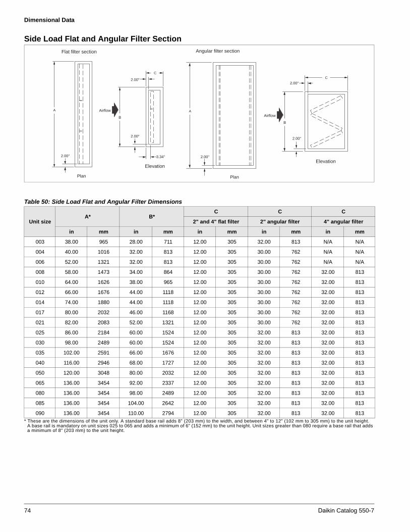
Dimensional Data
Side Load Flat and Angular Filter Section
* These are the dimensions of the unit only. A standard base rail adds 8" (203 mm) to the width, and between 4" to 12" (102 mm to 305 mm) to the unit height.A base rail is mandatory on unit sizes 025 to 065 and adds a minimum of 6" (152 mm) to the unit height. Unit sizes greater than 080 require a base rail that addsa minimum of 8" (203 mm) to the unit height.
Plan
A Airflow
B
Elevation
Flat filter section
C
2.00"
2.00"
3.34"2.00"
Angular filter section
Plan
2.00"
A
2.00"
Airflow
B
C
Elevation
2.00"
Table 50: Side Load Flat and Angular Filter Dimensions
Unit sizeA* B*
C C C
2" and 4" flat filter 2" angular filter 4" angular filter
in mm in mm in mm in mm in mm
003 38.00 965 28.00 711 12.00 305 32.00 813 N/A N/A
004 40.00 1016 32.00 813 12.00 305 30.00 762 N/A N/A
006 52.00 1321 32.00 813 12.00 305 30.00 762 N/A N/A
008 58.00 1473 34.00 864 12.00 305 30.00 762 32.00 813
010 64.00 1626 38.00 965 12.00 305 30.00 762 32.00 813
012 66.00 1676 44.00 1118 12.00 305 30.00 762 32.00 813
014 74.00 1880 44.00 1118 12.00 305 30.00 762 32.00 813
017 80.00 2032 46.00 1168 12.00 305 30.00 762 32.00 813
021 82.00 2083 52.00 1321 12.00 305 30.00 762 32.00 813
025 86.00 2184 60.00 1524 12.00 305 32.00 813 32.00 813
030 98.00 2489 60.00 1524 12.00 305 32.00 813 32.00 813
035 102.00 2591 66.00 1676 12.00 305 32.00 813 32.00 813
040 116.00 2946 68.00 1727 12.00 305 32.00 813 32.00 813
050 120.00 3048 80.00 2032 12.00 305 32.00 813 32.00 813
065 136.00 3454 92.00 2337 12.00 305 32.00 813 32.00 813
080 136.00 3454 98.00 2489 12.00 305 32.00 813 32.00 813
085 136.00 3454 104.00 2642 12.00 305 32.00 813 32.00 813
090 136.00 3454 110.00 2794 12.00 305 32.00 813 32.00 813
74 Daikin Catalog 550-7

Dimensional Data
Side Load Cartridge and Bag Filter Section
* Dimensions of unit only. A standard base rail adds 8" (203 mm) to the width, and between 4" to 12" (102 mm to 305 mm) to the unit height. A base rail ismandatory on unit sizes 025 and 065 and adds a minimum of 6" (152 mm) to the unit height. Unit sizes greater than 080 require a base rail that adds aminimum of 8" (203 mm) to the unit height.
Plan
A Airflow
B
Elevation
Cartridge filter section
C
2.00"
Bag filter section
Plan
2.00"
A
Airflow
B
C
Elevation
2.00"
3.34"
2.00"
2.00"
2.00"
3.34"
Table 51: Side Load Cartridge and Bag Filter Dimensions
Unit sizeA* B*
in mm in mm
003 38.00 965 26 660
004 40.00 1016 30 762
006 52.00 1321 30 762
008 58.00 1473 34.00 864
010 64.00 1626 36 914
012 66.00 1676 42 1067
014 74.00 1880 42 1067
017 80.00 2032 46.00 1168
021 82.00 2083 52.00 1321
025 86.00 2184 60.00 1524
030 98.00 2489 60.00 1524
035 102.00 2591 66.00 1676
040 116.00 2946 68.00 1727
050 120.00 3048 80.00 2032
065 136.00 3454 92.00 2337
080 136.00 3454 98.00 2489
085 136.00 3454 104.00 2642
090 136.00 3454 110.00 2794
Table 52: Filter Dimensions
Filter type C—all sizes
Cartridge in mm
4" w/2" Pre 14.00 356
4" w/4" Pre 16.00 406
12" w/2" Pre 22.00 559
12" w/4" Pre 24.00 610
Bag in mm
12" w/2" Pre 18.00 457
12" w/4" Pre 20.00 508
15" w/2" Pre 22.00 559
15" w/4" Pre 24.00 610
19" w/2 Pre 26.00 660
19" w/4" Pre 28.00 711
22" w/2" Pre 28.00 711
22" w/4" Pre 30.00 762
30" w/2" Pre 36.00 914
30" w/4" Pre 38.00 965
36" w/2" Pre 42.00 1067
36" w/4" Pre 44.00 1118
Daikin Catalog 550-7 75
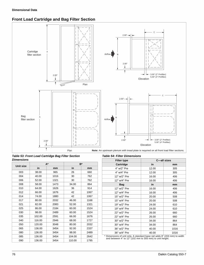
Dimensional Data
Front Load Cartridge and Bag Filter Section
* Dimensions of unit only. A standard base rail adds 8" (203 mm) to widthand between 4" to 12" (102 mm to 305 mm) to unit height.
Plan
AAirflow B
Elevation
Cartridge filter section
C
2.00"
Bag filter section
Plan
2.00"
AAirflow
B
C
Elevation
2.00"
3.00" (2" Prefilter)5.00" (4" Prefilter)
2.00"
2.00"
2.00"
3.00" (2" Prefilter)5.00" (4" Prefilter)
Note: An upstream plenum with tread plate is required on all front load filter sections.
Table 53: Front Load Cartridge Bag Filter Section Dimensions
Unit sizeA* B*
in mm in mm
003 38.00 965 26 660
004 40.00 1016 30 762
006 52.00 1321 30 762
008 58.00 1473 34.00 864
010 64.00 1626 36 914
012 66.00 1676 42 1067
014 74.00 1880 42 1067
017 80.00 2032 46.00 1168
021 82.00 2083 52.00 1321
025 86.00 2184 60.00 1524
030 98.00 2489 60.00 1524
035 102.00 2591 66.00 1676
040 116.00 2946 68.00 1727
050 120.00 3048 80.00 2032
065 136.00 3454 92.00 2337
080 136.00 3454 98.00 2489
085 136.00 3454 104.00 2642
090 136.00 3454 110.00 1795
Table 54: Filter Dimensions
Filter type C—all sizes
Cartridge in mm
4" w/2" Pre 12.00 305
4" w/4" Pre 12.00 305
12" w/2" Pre 16.00 406
12" w/4" Pre 16.00 406
Bag in mm
12" w/2" Pre 16.00 406
12" w/4" Pre 16.00 406
15" w/2" Pre 20.00 508
15" w/4" Pre 20.00 508
19" w/2" Pre 24.00 610
19" w/4" Pre 24.00 610
22" w/2" Pre 26.00 660
22" w/4" Pre 26.00 660
30" w/2" Pre 34.00 864
30" w/4" Pre 34.00 864
36" w/2" Pre 40.00 1016
36" w/4" Pre 40.00 1016
76 Daikin Catalog 550-7
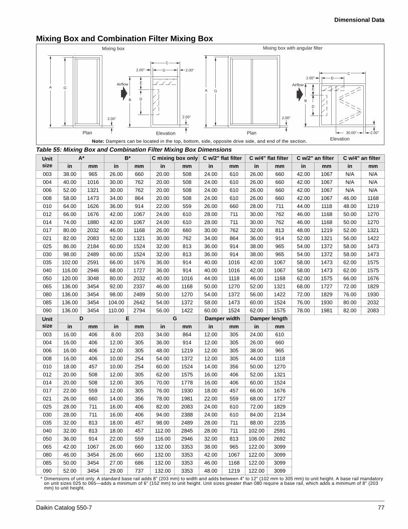
Dimensional Data
Mixing Box and Combination Filter Mixing Box
* Dimensions of unit only. A standard base rail adds 8" (203 mm) to width and adds between 4" to 12" (102 mm to 305 mm) to unit height. A base rail mandatoryon unit sizes 025 to 065—adds a minimum of 6" (152 mm) to unit height. Unit sizes greater than 080 require a base rail, which adds a minimum of 8" (203mm) to unit height.
Table 55: Mixing Box and Combination Filter Mixing Box Dimensions
Unit size
A* B* C mixing box only C w/2" flat filter C w/4" flat filter C w/2" an filter C w/4" an filter
in mm in mm in mm in mm in mm in mm in mm
003 38.00 965 26.00 660 20.00 508 24.00 610 26.00 660 42.00 1067 N/A N/A
004 40.00 1016 30.00 762 20.00 508 24.00 610 26.00 660 42.00 1067 N/A N/A
006 52.00 1321 30.00 762 20.00 508 24.00 610 26.00 660 42.00 1067 N/A N/A
008 58.00 1473 34.00 864 20.00 508 24.00 610 26.00 660 42.00 1067 46.00 1168
010 64.00 1626 36.00 914 22.00 559 26.00 660 28.00 711 44.00 1118 48.00 1219
012 66.00 1676 42.00 1067 24.00 610 28.00 711 30.00 762 46.00 1168 50.00 1270
014 74.00 1880 42.00 1067 24.00 610 28.00 711 30.00 762 46.00 1168 50.00 1270
017 80.00 2032 46.00 1168 26.00 660 30.00 762 32.00 813 48.00 1219 52.00 1321
021 82.00 2083 52.00 1321 30.00 762 34.00 864 36.00 914 52.00 1321 56.00 1422
025 86.00 2184 60.00 1524 32.00 813 36.00 914 38.00 965 54.00 1372 58.00 1473
030 98.00 2489 60.00 1524 32.00 813 36.00 914 38.00 965 54.00 1372 58.00 1473
035 102.00 2591 66.00 1676 36.00 914 40.00 1016 42.00 1067 58.00 1473 62.00 1575
040 116.00 2946 68.00 1727 36.00 914 40.00 1016 42.00 1067 58.00 1473 62.00 1575
050 120.00 3048 80.00 2032 40.00 1016 44.00 1118 46.00 1168 62.00 1575 66.00 1676
065 136.00 3454 92.00 2337 46.00 1168 50.00 1270 52.00 1321 68.00 1727 72.00 1829
080 136.00 3454 98.00 2489 50.00 1270 54.00 1372 56.00 1422 72.00 1829 76.00 1930
085 136.00 3454 104.00 2642 54.00 1372 58.00 1473 60.00 1524 76.00 1930 80.00 2032
090 136.00 3454 110.00 2794 56.00 1422 60.00 1524 62.00 1575 78.00 1981 82.00 2083
Unit size
D E G Damper width Damper length
in mm in mm in mm in mm in mm
003 16.00 406 8.00 203 34.00 864 12.00 305 24.00 610
004 16.00 406 12.00 305 36.00 914 12.00 305 26.00 660
006 16.00 406 12.00 305 48.00 1219 12.00 305 38.00 965
008 16.00 406 10.00 254 54.00 1372 12.00 305 44.00 1118
010 18.00 457 10.00 254 60.00 1524 14.00 356 50.00 1270
012 20.00 508 12.00 305 62.00 1575 16.00 406 52.00 1321
014 20.00 508 12.00 305 70.00 1778 16.00 406 60.00 1524
017 22.00 559 12.00 305 76.00 1930 18.00 457 66.00 1676
021 26.00 660 14.00 356 78.00 1981 22.00 559 68.00 1727
025 28.00 711 16.00 406 82.00 2083 24.00 610 72.00 1829
030 28.00 711 16.00 406 94.00 2388 24.00 610 84.00 2134
035 32.00 813 18.00 457 98.00 2489 28.00 711 88.00 2235
040 32.00 813 18.00 457 112.00 2845 28.00 711 102.00 2591
050 36.00 914 22.00 559 116.00 2946 32.00 813 106.00 2692
065 42.00 1067 26.00 660 132.00 3353 38.00 965 122.00 3099
080 46.00 3454 26.00 660 132.00 3353 42.00 1067 122.00 3099
085 50.00 3454 27.00 686 132.00 3353 46.00 1168 122.00 3099
090 52.00 3454 29.00 737 132.00 3353 48.00 1219 122.00 3099
Mixing box with angular filter
2.00"
Elevation2.00"
Airflow
CD
B
D
E
30.00"Plan
2.00"
GA
Plan Elevation
Mixing box
GAAirflow
B D
E
2.00"
C
D 2.00"
2.00"2.00"
Note: Dampers can be located in the top, bottom, side, opposite drive side, and end of the section.
Daikin Catalog 550-7 77

Dimensional Data
Economizer Section
* These are the dimensions of the unit only. Curb-ready base adds 6" (152 mm) to the unit height. A standard base rail adds 8" (203 mm) to the width, andbetween 4" to 12" (102 mm to 305 mm) to the unit height. A base rail—mandatory on unit sizes 025 to 065—adds a minimum of 6" (152 mm) to the unit height.Unit sizes greater than 080 require a base rail that adds a minimum of 8" (203 mm) to the unit height.
Table 56: Economizer DimensionsUnit size
A* B* D G Damper width Damper lengthin mm in mm in mm in mm in mm in mm
003 38.00 965 26.00 660 16.00 406 34.00 864 12.00 305 24.00 610004 40.00 1016 30.00 762 16.00 406 36.00 914 12.00 305 26.00 660006 52.00 1321 30.00 762 16.00 406 48.00 1219 12.00 305 38.00 965008 58.00 1473 34.00 864 16.00 406 54.00 1372 12.00 305 44.00 1118010 64.00 1626 36.00 914 18.00 457 60.00 1524 14.00 356 50.00 1270012 66.00 1676 42.00 1067 20.00 508 62.00 1575 16.00 406 52.00 1321014 74.00 1880 42.00 1067 20.00 508 70.00 1778 16.00 406 60.00 1524017 80.00 2032 46.00 1168 22.00 559 76.00 1930 18.00 457 66.00 1676021 82.00 2083 52.00 1321 26.00 660 78.00 1981 22.00 559 68.00 1727025 86.00 2184 60.00 1524 28.00 711 82.00 2083 24.00 610 72.00 1829030 98.00 2489 60.00 1524 28.00 711 94.00 2388 24.00 610 84.00 2134035 102.00 2591 66.00 1676 32.00 813 98.00 2489 28.00 711 88.00 2235040 116.00 2946 68.00 1727 32.00 813 112.00 2845 28.00 711 102.00 2591050 120.00 3048 80.00 2032 36.00 914 116.00 2946 32.00 813 106.00 2692065 136.00 3454 92.00 2337 42.00 1067 132.00 3353 38.00 965 122.00 3099080 136.00 3454 98.00 3489 46.00 1168 132.00 3353 42.00 1067 122.00 3099085 136.00 3454 104.00 2642 50.00 1270 132.00 3353 46.00 1168 122.00 3099090 136.00 3454 110.00 2794 52.00 1321 132.00 3353 48.00 1219 122.00 3099
Unit size
C econ. only C w/2" flat filter C w/4" flat filter C w/2" an filter C w/4" an filter
in mm in mm in mm in mm in mm003 40.00 1016 44.00 1118 46.00 1168 62.00 1575 N/A N/A004 40.00 1016 44.00 1118 46.00 1168 62.00 1575 N/A N/A006 40.00 1016 44.00 1118 46.00 1168 62.00 1575 N/A N/A008 40.00 1016 44.00 1118 46.00 1168 62.00 1575 66.00 1676010 44.00 1118 48.00 1219 50.00 1270 66.00 1676 70.00 1778012 48.00 1219 52.00 1321 54.00 1372 70.00 1778 74.00 1880014 48.00 1219 52.00 1321 54.00 1372 70.00 1778 74.00 1880017 52.00 1321 56.00 1422 58.00 1473 74.00 1880 78.00 1981021 60.00 1524 64.00 1626 66.00 1676 82.00 2083 86.00 2184025 64.00 1626 68.00 1727 70.00 1778 86.00 2184 90.00 2286030 64.00 1626 68.00 1727 70.00 1778 86.00 2184 90.00 2286035 72.00 1829 76.00 1930 78.00 1981 94.00 2388 98.00 2489040 72.00 1829 76.00 1930 78.00 1981 94.00 2388 98.00 2489050 80.00 2032 84.00 2134 86.00 2184 102.00 2591 106.00 2692065 92.00 2337 96.00 2438 98.00 2489 114.00 2896 118.00 2997080 100.00 2540 108.00 2743 112.00 2845 144.00 3658 152.00 3861085 108.00 2743 116.00 2946 120.00 3048 152.00 3861 160.00 4064090 112.00 2845 120.00 3048 124.00 3150 156.00 3962 164.00 4166
Elevation
Plan
2.00"
2.00"
AAirflow
B
G
2.00" 2.00"
C
D D4"
Note: Dampers can be located in the top, bottom, drive side and opposite drive side, and end of the section.
78 Daikin Catalog 550-7

Dimensional Data
Blenders
Note: The depth of an air mixer section varies depending on components adjacent to the mixing device. The catalog dimensions shown are for a two-blender system except sizes 040 to 090, which are three-blender systems. For applications other than this, the depth dimension varies. Use Vision Select Tools software for more detailed dimensional information.
* These are the dimensions of the unit only. A standard base rail adds 8" (203 mm) to the width, and between 4" to 12" (102 mm to 305 mm) to the unit height.** All values represent Kees blenders located after filters.
A 6" (152 mm) base rail is mandatory on unit sizes 025 to 065. An 8" (203 mm) base rail is mandatory on all sizes 080 and larger.
Elevation
Plan
2.00"
A
Airflow
B
C
2.00"
2.00"
Table 57: Blender Product Series IV Dimensions
Unit sizeA* B* C
in mm in mm in mm
003 38.00 965 26.00 660 N/A N/A
004 40.00 1016 30.00 762 12.00 305
006 52.00 1321 30.00 762 14.00 356
008 58.00 1473 34.00 864 16.00 406
010 64.00 1626 36.00 914 18.00 457
012 66.00 1676 42.00 1067 20.00 508
014 74.00 1880 42.00 1067 22.00 559
017 80.00 2032 46.00 1168 24.00 610
021 82.00 2083 52.00 1321 28.00 711
025 86.00 2184 60.00 1524 32.00 813
030 98.00 2489 60.00 1524 34.00 864
035 102.00 2591 66.00 1676 36.00 914
040 116.00 2946 68.00 1727 38.00 965
050 120.00 3048 80.00 2032 46.00 1168
065 136.00 3454 92.00 2337 52.00 1321
080 136.00 3454 98.00 3489 54.00 1372
085 136.00 3454 104.00 2642 56.00 1422
090 136.00 3454 110.00 2794 58.00 1473
Table 58: Kees Blender Dimensions
Unit sizeA** B* C
in mm in mm in mm
003 38.00 965 26.00 660 N/A N/A
004 40.00 1016 30.00 762 N/A N/A
006 52.00 1321 30.00 762 22.00 559
008 58.00 1473 34.00 864 24.00 610
010 64.00 1626 36.00 914 26.00 660
012 66.00 1676 42.00 1067 28.00 711
014 74.00 1880 42.00 1067 30.00 762
017 80.00 2032 46.00 1168 32.00 813
021 82.00 2083 52.00 1321 36.00 914
025 86.00 2184 60.00 1524 38.00 965
030 98.00 2489 60.00 1524 40.00 1016
035 102.00 2591 66.00 1676 42.00 1067
040 116.00 2946 68.00 1727 38.00 965
050 120.00 3048 80.00 2032 42.00 1067
065 136.00 3454 92.00 2337 46.00 1168
080 136.00 3454 98.00 3489 56.00 1422
085 136.00 3454 104.00 2642 58.00 1473
090 136.00 3454 110.00 2794 58.00 1473
Daikin Catalog 550-7 79

Dimensional Data
Access Doors
Access doors are an option for most sections. Fan sections are always provided with a door on one side of the unit. Access door size varies with the size of the section; they are never wider than 30". On most components doors can be selected as inward opening. Once the door is opened outward, the opening is 2" less than the door height and width because there is a 1" flange around the opening. Once the door is opened inward, the opening is 3" less than the door height and width since there is no flange around the opening. Door height is always 4" shorter than section height unless the section has a drain connection. If the section has a drain pan, then the door is 6" shorter than the section height. The maximum door height is 64", except filter section doors, which are equal to section height minus 4".
* Dimensions of the unit only. Curb-ready base adds 6" (152 mm) to unitheight. A standard base rail adds 8" (203 mm) to width and between 4" to12" (102 mm to 305 mm) to unit height. A 6" (152 mm) base rail ismandatory on unit sizes 025 to 065. An 8" (203 mm) base rail ismandatory on all sizes 080 and larger.
Elevation
2.00"
D
C
2.00" 1.00" Flange
1.00"
1.00" Flange
B
Plan
B
Table 59: Access Door DimensionsUnit cross section
Unit sizeA* B*
in mm in mm003 38.00 965 26.00 660004 40.00 1016 30.00 762006 52.00 1321 30.00 762008 58.00 1473 34.00 864010 64.00 1626 36.00 914012 66.00 1676 42.00 1067014 74.00 1880 42.00 1067017 80.00 2032 46.00 1168021 82.00 2083 52.00 1321025 86.00 2184 60.00 1524030 98.00 2489 60.00 1524035 102.00 2591 66.00 1676040 116.00 2946 68.00 1727050 120.00 3048 80.00 2032065 136.00 3454 92.00 2337080 136.00 3454 98.00 3489085 136.00 3454 104.00 2642090 136.00 3454 110.00 2794
Table 60: Door WidthsAvailable door widths based on section length
C D
in mm in mm
12.00 305 8.00 203
14.00 356 10.00 254
16.00 406 12.00 305
18.00 457 14.00 356
20.00 508 16.00 406
22.00 559 18.00 457
24.00 610 20.00 508
26.00 660 22.00 559
28.00 711 24.00 610
30.00 762 26.00 660
32.00 813 28.00 711
34.00 864 30.00 762
36.00 914 28.00 711
38.00 965 30.00 762
40.00 1016 30.00 762
42.00 1067 30.00 762
44.00 1118 30.00 762
46.00 1168 30.00 762
48.00 1219 30.00 762
50.00 1270 30.00 762
52.00 1321 30.00 762
54.00 1372 30.00 762
80 Daikin Catalog 550-7
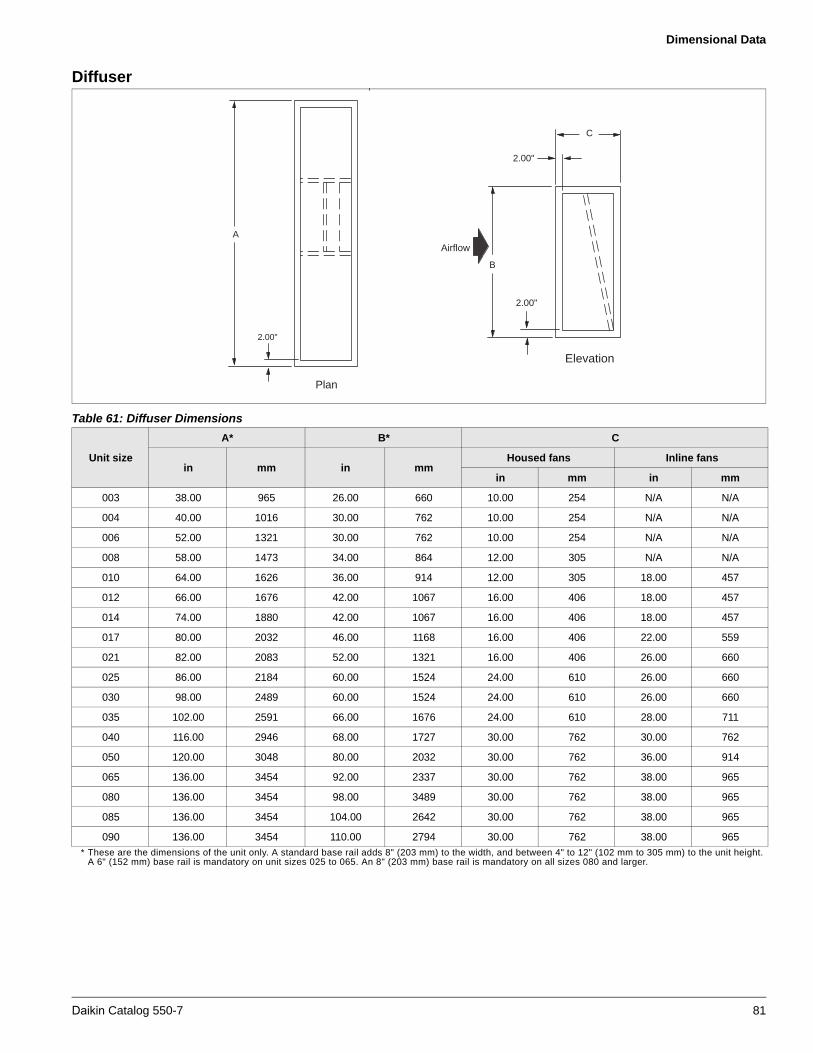
Dimensional Data
Diffuser
* These are the dimensions of the unit only. A standard base rail adds 8" (203 mm) to the width, and between 4" to 12" (102 mm to 305 mm) to the unit height.A 6" (152 mm) base rail is mandatory on unit sizes 025 to 065. An 8" (203 mm) base rail is mandatory on all sizes 080 and larger.
Plan
2.00"
A
Airflow
B
Elevation
2.00"
2.00"
C
Table 61: Diffuser Dimensions
Unit size
A* B* C
in mm in mmHoused fans Inline fans
in mm in mm
003 38.00 965 26.00 660 10.00 254 N/A N/A
004 40.00 1016 30.00 762 10.00 254 N/A N/A
006 52.00 1321 30.00 762 10.00 254 N/A N/A
008 58.00 1473 34.00 864 12.00 305 N/A N/A
010 64.00 1626 36.00 914 12.00 305 18.00 457
012 66.00 1676 42.00 1067 16.00 406 18.00 457
014 74.00 1880 42.00 1067 16.00 406 18.00 457
017 80.00 2032 46.00 1168 16.00 406 22.00 559
021 82.00 2083 52.00 1321 16.00 406 26.00 660
025 86.00 2184 60.00 1524 24.00 610 26.00 660
030 98.00 2489 60.00 1524 24.00 610 26.00 660
035 102.00 2591 66.00 1676 24.00 610 28.00 711
040 116.00 2946 68.00 1727 30.00 762 30.00 762
050 120.00 3048 80.00 2032 30.00 762 36.00 914
065 136.00 3454 92.00 2337 30.00 762 38.00 965
080 136.00 3454 98.00 3489 30.00 762 38.00 965
085 136.00 3454 104.00 2642 30.00 762 38.00 965
090 136.00 3454 110.00 2794 30.00 762 38.00 965
Daikin Catalog 550-7 81
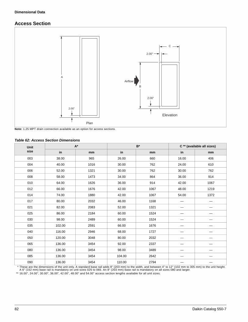
Dimensional Data
Access Section
Note: 1.25 MPT drain connection available as an option for access sections.
* These are the dimensions of the unit only. A standard base rail adds 8" (203 mm) to the width, and between 4" to 12" (102 mm to 305 mm) to the unit height.A 6" (152 mm) base rail is mandatory on unit sizes 025 to 065. An 8" (203 mm) base rail is mandatory on all sizes 080 and larger.
** 16.00", 24.00", 30.00", 36.00", 42.00", 48.00" and 54.00" access section lengths available for all unit sizes.
Plan
2.00"
A
Airflow
B
Elevation
2.00"
2.00"
C
Table 62: Access Section Dimensions
Unit size
A* B* C ** (available all sizes)
in mm in mm in mm
003 38.00 965 26.00 660 16.00 406
004 40.00 1016 30.00 762 24.00 610
006 52.00 1321 30.00 762 30.00 762
008 58.00 1473 34.00 864 36.00 914
010 64.00 1626 36.00 914 42.00 1067
012 66.00 1676 42.00 1067 48.00 1219
014 74.00 1880 42.00 1067 54.00 1372
017 80.00 2032 46.00 1168 — —
021 82.00 2083 52.00 1321 — —
025 86.00 2184 60.00 1524 — —
030 98.00 2489 60.00 1524 — —
035 102.00 2591 66.00 1676 — —
040 116.00 2946 68.00 1727 — —
050 120.00 3048 80.00 2032 — —
065 136.00 3454 92.00 2337 — —
080 136.00 3454 98.00 3489 — —
085 136.00 3454 104.00 2642 — —
090 136.00 3454 110.00 2794 — —
82 Daikin Catalog 550-7

Dimensional Data
Internal/External Face and Bypass Sections
* These are the dimensions of the unit only. A standard base rail adds 8" (203 mm) to the width, and between 4" to 12" (102 mm to 305 mm) to the unit height.A 6" (152 mm) base rail is mandatory on unit sizes 025-065. An 8" (203 mm) base rail is mandatory on all sizes 080 and larger.
** Right angle face and bypass dampers are mandatory on unit sizes 040 and larger.
Elevation
Plan
2.00"
A
2.00"
Airflow
B
2.00"
12.00"
Plan
A
2.00"
Elevation
2.00"
AirflowB
2.00"
D
C
CabinetHeight
Internal face and bypass with small and medium face area coil
External face and bypass with large face area coil
Table 63: Internal and External Faced and Bypass Dimensions
Unit sizeA* B* C, internal C, external D
in mm in mm in mm in mm in mm
003 38.00 965 26.00 660 12.00 305 18.00 457 10.00 254
004 40.00 1016 30.00 762 12.00 305 18.00 457 10.00 254
006 52.00 1321 30.00 762 12.00 305 18.00 457 10.00 254
008 58.00 1473 34.00 864 12.00 305 20.00 508 10.00 254
010 64.00 1626 36.00 914 12.00 305 22.00 559 12.00 305
012 66.00 1676 42.00 1067 12.00 305 24.00 610 16.00 406
014 74.00 1880 42.00 1067 12.00 305 24.00 610 16.00 406
017 80.00 2032 46.00 1168 12.00 305 26.00 660 16.00 406
021 82.00 2083 52.00 1321 12.00 305 30.00 762 22.00 559
025 86.00 2184 60.00 1524 12.00 305 32.00 813 24.00 610
030 98.00 2489 60.00 1524 12.00 305 32.00 813 24.00 610
035 102.00 2591 66.00 1676 12.00 305 34.00 864 26.00 660
040** 116.00 2946 68.00 1727 12.00 305 38.00 965 26.00 660
050** 120.00 3048 80.00 2032 12.00 305 44.00 1118 32.00 813
065** 136.00 3454 92.00 2337 12.00 305 50.00 1270 36.00 914
080** 136.00 3454 98.00 3489 12.00 305 54.00 1372 38.00 965
085** 136.00 3454 104.00 2642 12.00 305 56.00 1422 42.00 1067
090** 136.00 3454 110.00 2794 12.00 305 58.00 1473 1473 1118
Daikin Catalog 550-7 83

Dimensional Data
Discharge or Return Plenum
Return and discharge plenums are available with openings in the top, bottom, upper end, lower end, drive side, or opposite drive side. The opening size does not vary with the location. All openings have a 1" flange recessed in opening. 1.25 MPT drain connection available as an option for plenum sections.
* These are the dimensions of the unit only. A standard base rail adds 8" (203 mm) to the width, and between 4" to 12" (102 mm to 305 mm) to the unit height.A 6" (152 mm) base rail is mandatory on unit sizes 025 to 065. An 8" (203 mm) base rail is mandatory on all sizes 080 and larger.
Elevation
Plan
A
Airflow
B
2.00"
D
E
2.00"
2.00"1.00"
Flange
1.00"Flange
C
Optional OpeningLocation
Optional OpeningLocation
Optional OpeningLocation
Optional OpeningLocation
Optional OpeningLocation
Optional OpeningLocation
Table 64: Discharge or Return Plenum Dimensions
Unit sizeA* B* C D E
in mm in mm in mm in mm in mm
003 38.00 965 26.00 660 14.00 356 10.00 254 34.00 864
004 40.00 1016 30.00 762 16.00 406 12.00 305 36.00 914
006 52.00 1321 30.00 762 16.00 406 12.00 305 48.00 1219
008 58.00 1473 34.00 864 18.00 457 14.00 356 54.00 1372
010 64.00 1626 36.00 914 20.00 508 16.00 406 60.00 1524
012 66.00 1676 42.00 1067 22.00 559 18.00 457 62.00 1575
014 74.00 1880 42.00 1067 22.00 559 18.00 457 70.00 1778
017 80.00 2032 46.00 1168 24.00 610 20.00 508 76.00 1930
021 82.00 2083 52.00 1321 28.00 711 24.00 610 78.00 1981
025 86.00 2184 60.00 1524 30.00 762 26.00 660 82.00 2083
030 98.00 2489 60.00 1524 30.00 762 26.00 660 94.00 2388
035 102.00 2591 66.00 1676 32.00 813 28.00 711 98.00 2489
040 116.00 2946 68.00 1727 32.00 813 28.00 711 112.00 2845
050 120.00 3048 80.00 2032 38.00 965 34.00 864 116.00 2946
065 136.00 3454 92.00 2337 42.00 1067 38.00 965 132.00 3353
080 136.00 3454 98.00 3489 42.00 1067 44.00 1118 132.00 3353
085 136.00 3454 104.00 2642 44.00 1118 48.00 1219 132.00 3353
090 136.00 3454 110.00 2794 46.00 1168 50.00 1270 132.00 3353
84 Daikin Catalog 550-7

Dimensional Data
Sound Attenuator Section
* These are the dimensions of the unit only. A standard base rail adds 8" (203 mm) to the width, and between 4" to 12" (102 mm to 305 mm) to the unit height.A 6" (152 mm) base rail is mandatory on unit sizes 025 to 065. An 8" (203 mm) base rail is mandatory on all sizes 080 and larger.
** 40.00", 52.00" and 64.00" actuator section lengths available for all unit sizes.
Elevation
Plan
A Airflow
C
2.00"
B
2.00"
2.00"
Table 65: Sound Attenuator Dimensions
Unit sizeA* B* C** (available all sizes)
in mm in mm in mm
003 38.00 965 26.00 660
004 40.00 1016 30.00 762 40.00 1016
006 52.00 1321 30.00 762 52.00 1321
008 58.00 1473 34.00 864 64.00 1626
010 64.00 1626 36.00 914 — —
012 66.00 1676 42.00 1067 — .—
014 74.00 1880 42.00 1067 — —
017 80.00 2032 46.00 1168 — —
021 82.00 2083 52.00 1321 — —
025 86.00 2184 60.00 1524 — —
030 98.00 2489 60.00 1524 — —
035 102.00 2591 66.00 1676 — —
040 116.00 2946 68.00 1727 — —
050 120.00 3048 80.00 2032 — —
065 136.00 3454 92.00 2337 — —
080 136.00 3454 98.00 3489 — —
085 136.00 3454 104.00 2642 — —
090 136.00 3454 110.00 2794 — —
Daikin Catalog 550-7 85

Dimensional Data
Base Rail
Note: The base rail is available in heights of 4", 6", 8", 10", and 12".
Airflow
2.00"
CL
Height
2.00"dia. hole
0.625"dia. hole
2.00" 2.00"
4.00"
1.00"
4.00"
1.00"
UnitWidth
Unit ShippingSection Length
End View
Plan View
86 Daikin Catalog 550-7

Electrical Data
Electrical Data
Supply Power Wiring1 Units required three phase power supply.
2 Allowable voltage tolerances:
a 60 HertzNameplate 208 V: Min. 187 V, max. 229 VNameplate 230 V: Min. 207 V, max. 253 VNameplate 460 V: Min. 414 V, max. 506 VNameplate 575 V: Min. 518 V, max. 633 V
3 Minimum Circuit Ampacity (MCA) calculation:Note: If a unit is provided with multiple power connections, each must be considered alone in selecting power wiring components.
For units with cooling and heating:MCA = 1.25 × largest load + sum of all other loads
Note – Control circuit ampacity does not need to be considered in the calculation for wire sizing ampacity. If the unit is provided with one or more fan section lights, they are powered from the separate 15 amp (minimum), 120 V supply required by the NEC for the unit convenience outlet.
4 Size wires in accordance with Table 310-16 or 310-19 of the National Electrical Code.
5 Wires should be sized for a maximum of 3% voltage drop.
Table 66: Recommended Power Wiring
AMPACITY
NO. OF POWER
WIRES PER PHASE
WIREGAUGE
INSULATIONRATING
(0°C)AMPACITY
30 1 10 75 30
40 1 8 75 40
55 1 6 75 55
70 1 4 75 70
85 1 3 75 85
95 1 2 75 95
130 1 1 75 130
150 1 1/0 75 150
175 1 2/0 75 175
200 1 3/0 75 200
230 1 4/0 75 230
255 1 250 75 255
300 2 1/0 75 300
350 2 2/0 75 350
400 2 3/0 75 400
460 2 4/0 75 460
510 2 250 75 510
600 3 3/0 75 600
690 3 4/0 75 690
765 3 250 75 765
Daikin Catalog 550-7 87

Engineering Guide Specification
Engineering Guide Specification
PART 1: GENERAL
1.01 SECTION INCLUDES
A Indoor air handling units
1.02 REFERENCES
A AFBMA 9 - Load Ratings and Fatigue Life for Ball Bearings
B AMCA 99 - Standards Handbook
C AMCA 210 - Laboratory Methods of Testing Fans for Rating Purposes
D AMCA 300 - Test Code for Sound Rating Air Moving Devices
E AMCA 500 - Test Methods for Louver, Dampers, and Shutters
F ARI 410 - Forced-Circulation Air-Cooling and Air-Heating Coils
G ARI 430 - Central-Station Air-Handling Units
H ARI 435 - Application of Central-Station Air-Handling Units
I ASTMB117 – Standard Practice for Operating Salt Spray Apparatus
J NEMA MG1 - Motors and Generators
K NFPA 70 - National Electrical Code
L SMACNA - HVAC Duct Construction Standards - Metal and Flexible
M UL 723 – Test for Surface Burning Characteristics of Building Materials
N UL 900 - Test Performance of Air Filter Units.
O UL 1995 – Standard for Heating and Cooling Equipment
P UL 94 – Test for Flammability of Plastic Materials for Parts in Devices and Appliances
Q IBC 2000, 2003 – International Building Code
R NFPA 90A – Standard for the Installation of Air Conditioning and Ventilating Systems
S NFPA 5000 – Building Construction and Safety Code
T ASHRAE 90.1 Energy Code
U ARI Standard 1060 – Rating Air-to-Air Heat Exchangers for Energy Recovery Ventilation Equipment
V GSA 2003 Facilities Standard - 5.9 HVAC Systems and Components
1.03 SUBMITTALS
A Shop Drawings: Indicate assembly, unit dimensions, weight loading, required clearances, construction details, field connection details, and electrical characteristics and connection requirements. Computer generated fan curves for each air handling unit shall be submitted with specific design operating point noted. A computer generated psychometric chart shall be submitted for each cooling coil with design points and final operating point clearly noted. Sound data for discharge, radiated and return positions shall be submitted by octave band for each unit. Calculations for required baserail heights to satisfy condensate trapping requirements of cooling coil shall be included.
B Product Data:
1 Provide literature that indicates dimensions, weights, capacities, ratings, fan performance, and electrical characteristics and connection requirements.
2 Provide data of filter media, filter performance data, filter assembly, and filter frames.
C Manufacturer’s Installation Instructions.
1.04 QUALIFICATIONS
A Manufacturers specializing in manufacturing Air Handling Units specified in this section must prove minimum five years documented experience and issue a complete catalog on total product.
1.05 SAFETY AGENCY LISTED & CERTIFICATION
A Air handling units shall be cETLus safety listed that conforms to UL Standard 1995 and CAN/CSA Standard C22.2 No. 236. Units shall be accepted for use in New York City by the Department of Building, MEA 342-99-E.
B Air handler furnished with double width, double inlet (DWDI) and/or plenum fans shall be certified in accordance with the central station air handling units certification program, which is based on ARI 430. (NOTE: Above does not apply to fan array)
C Air handling unit water heating & cooling coils shall be certified in accordance with the forced circulation air cooling and air heating coils certification program, which is based on ARI Standard 410.
1.06 DELIVERY, STORAGE, AND HANDLING
A Deliver, store, protect and handle products to site.
B Accept products on site in factory-fabricated protective containers, with factory-installed shipping skids. Inspect for damage.
C Store in clean dry place and protect from weather and construction traffic. Handle carefully to avoid damage to components, enclosures, and finish.
88 Daikin Catalog 550-7

Engineering Guide Specification
PART 2: PRODUCTS
2.01 MANUFACTURERS
A The following manufacturers are approved for use. No substitutions will be permitted.
1 Daikin as basis of design 2 Miller-Picking
3 Temtrol
4 Scott-Springfield
5 Racan-Carrier Company
2.02 GENERAL DESCRIPTION
A Configuration: Fabricate as detailed on drawings.
B Performance: Conform to ARI 430. See schedules on prints. (NOTE: Above does not apply to fan array)
C Acoustics: Sound power levels (dB) for the unit shall not exceed the following specified levels. The manufacturer shall provide the necessary sound treatment to meet these levels if required.
D [IBC Certification
1 All components included herein are designed, manufactured and independently tested, rated and certified to meet the seismic compliance standards of the 2009 International Building Code. Components designated for use in systems that are life safety, toxic, high hazard, combustible or flammable shall meet the on line, anchorage and load path requirements for life safety as defined in IBC sections 1621.1.6, 1621.3.3, 1707.7.2, and IBC Commentary, Volume II, section 1621.1.6, IBC notes pertaining to the release of hazardous material. All components used as part of a system other than the above shall meet as a minimum, all load path and anchorage standards for components as outlined in IBC section 1621.3.3 & 1707.7.2.
2 Certification is good for [Fp/Wp = 2.89 gs and Sds = 1.29 gs obtained from a “maximum considered earth quake short period spectral response acceleration Ss of 1.93.] [Fp/Wp = 4.42 gs and Sds = 1.96 gs obtained from a “maximum considered earth quake short period spectral response acceleration Ss of 2.94.]
3 All completed component assemblies shall be clearly labelled for field inspection. Seismic Compliance Labels shall include the manufacturer’s identification, designation of certified models, definitive information describing the product’s compliance characteristics, and the Independent Certifying Agency’s name and report identification.
4 In addition to all seismic requirements for IBC Certification listed elsewhere in the project specification, manufacturer’s submittals shall include :
5 Certificate of Compliance from the Independent Certifying Agency clearly indicating that components supplied on this project are included in the component manufacturer’s Certificate of Compliance.
6 Clear installation instructions including all accessory components that are part of the overall component installation.]
2.03 UNIT CONSTRUCTION
A Fabricate unit with 16 gauge channel posts and panels secured with mechanical fasteners. All panels, access doors, and ship sections shall be sealed with permanently applied bulb-type gasket. Shipped loose gasketing is not allowed.
1 Panels and access doors shall be constructed as a 2-inch (50-mm) nominal thick; thermal broke double wall assembly, injected with foam insulation for an R-value of not less than R-13. The outer panel shall be constructed of G90 galvanized [G60 painted galvanized] [18-gauge] steel. The inner liner shall be constructed of G90 galvanized [solid stainless] steel.
2 Panel deflection shall not exceed L/240 ratio at 125% of design static pressure, maximum positive or negative 8inches of static pressure. Deflection shall be measured at the midpoint of the panel height.
3 The casing leakage rate shall not exceed [.5 cfm per square foot of cabinet area at 6 inches of negative static pressure or 5 inches of positive static pressure (.0025 m3/s per square meter of cabinet area at 1.24 kPa static pressure)] [1% of supply air volume at design static pressure up to positive or negative 8 inches (1.99 kPa)] or [ASHRAE 111 CL 6 at design pressure up to positive or negative 8 inches (1.99 kPa), where casing leakage (cfm/100 ft2 of casing surface are) = CL× P0.65].
4 Module to module assembly shall be accomplished with an overlapping, full perimeter, insulated, internal splice joint sealed with bulb type gasketing on both mating modules to minimize on-site labor and meet indoor air quality standards.
Octave Band at Center Frequency (Hz)
63 125 250 500 1000 2000 4000 8000
Radiated
Discharge
Return
Daikin Catalog 550-7 89

Engineering Guide Specification
5 Factory leakage test available for Vision Plus units. The unit manufacturer shall provide a witnessed factory leak test on selected units. The cabinet shall be tested at the unit’s positive and negative maximum design operating static pressure, up to 8" of differential static pressure across the cabinet exterior walls for the entire unit. Cabinet leakage shall not exceed Class 6 leakage per ASHRAE Standard 111. All supply and return opening shall be sealed. Air pressure and flow shall be measured by a third party calibrated and certified apparatus. The testing shall be performed at the factory. Owner’s representative shall select on unit to be tested at the time of order. A written test report shall be prepared by the manufacturer and issued to the owner’s representative.
6 Factory panel deflection testing available for Vision Plus units. The unit manufacturer shall provide a factory deflection test on one unit at the unit’s positive and negative maximum design operating static pressure, up to 8" of differential static pressure across the cabinet exterior walls for the entire unit. A deflection limit of L/240 will be demonstrated at this time. “L” is defined as the height of a panel on the side of the unit. Measurement shall be at the mid-point of “L” along the largest panel on one side. Owner’s representative shall select on unit to be tested at the time of order. A written test report shall be prepared by the manufacturer and issued to the owner’s representative.
7 [A sound baffle shall be secured to the inner liner and constructed of G90 galvanized perforated steel filled with 3 lb. per cu ft. density, neoprene coated, glass fiber insulation.]
8 [An optional .125" thick aluminium treadplate shall be secured to the floor panel.]
9 [Entire unit shall have a [4] [6] [8] [10] [12]-inch full perimeter base rail for structural rigidity and condensate trapping. The following calculation shall determine the required height of the baserail to allow for adequate drainage. Use the largest pressure to determine base rail height. [(Negative)(Positive) static pressure (in)] (2) + 4" = required baserail height. Should the unit baserail not be factory supplied at this height, the contractor is required to supply a concrete housekeeping pad to make up the difference.]
B Access Doors shall be flush mounted to cabinetry, with minimum of two six inch long stainless steel piano-type hinges, latch and full size (4.5" minimum) handle assembly (provide inspection window for fan section). Door shall swing outward for unit sections under negative pressure (inward for unit sections under positive pressure). Doors limited from swinging inward (such as side access filter sections) on positive pressure sections, shall have a secondary latch to relieve pressure and prevent injury upon access.
C Construct drain pans from [microbial resistant coated galvanized steel] [stainless steel] with cross break and double sloping pitch to drain connection. Provide drain pans under cooling coil section [fan section]. Drain connection centerline shall be a minimum of 3" above the base rail to aid in proper condensate trapping. Drain connections that protrude from the base rail are not acceptable. There must be a full 2" thickness of insulation under drain pan.
2.04 SUPPLY / RETURN FANS
A Provide [DWDI forward-curved] [DWDI airfoil] [belt-drive airfoil plenum] [direct-drive airfoil plenum] [inline] [DWDI forward curved twin] [fan array] supply [return] fan(s). Fan assemblies including fan, motor and sheaves shall be dynamically balanced by the manufacturer on all three planes and at all bearing supports. Manufacturer must ensure maximum fan RPM is below the first critical speed.
Fan array
1 Fan array shall have [three] [four] [six], 11 blade direct drive, [class II] [class III] fans with [1" spring isolation] and all painted construction
2 Walk in access section placed downstream [with motor removal hoist].
3 [Manual block-off] [Isolation damper] mounted upstream of fan for isolation of individual fans.
4 Single source power motor control panel with short circuit protection [Non-fused disconnect] factory wired from panel to motors in conduit. Daikin brand VFD’s [2 for 4 fans] [3 for 3 fans] [3 for 6 fans] [Fan on-off and speed control by others shall be provided.
Multiple direct drive fans
1 Unit shall have [two] [three] [9] [12] blade direct drive class II fans with [2" spring isolation] [rubber-in-shear isolation (fan sizes 36 and smaller)] [2" seismic isolation].
2 [Manual block-off] [Isolation damper [with actuator]] mounted upstream of fan for isolation of individual fans.
3 [Single source power motor control panel with short circuit protection and [Non-fused disconnect] [fused disconnect] [Circuit breaker] factory wired from panel to motors in conduit. Variable speed control by [McQauay brand VFD(s)] [ABB] [Danfoss].] [Fan on-off and speed control by others shall be provided.]
B Bearings shall be self-aligning, grease lubricated, ball or roller bearings with extended copper lubrication lines to access side of unit. Grease fittings shall be attached to the fan base assembly near access door. If not supplied at the factory, contractor shall mount copper lube lines in the field.
90 Daikin Catalog 550-7

Engineering Guide Specification
C Fan and motor shall be mounted internally on a steel base. Factory mount motor on slide base that can be slid out the side of unit if removal is required. Provide access to motor, drive, and bearings through hinged access door. Fan and motor assembly shall be mounted on [rubber-in-shear vibration type isolators inside cabinetry.] [2" deflection spring vibration type isolators inside cabinetry] [unit base, rigid mounted.] [Seismic snubbers shall be provided.]
2.05 BEARINGS AND DRIVES
(Not applicable for fan array or direct drive fans)
A Bearings: Basic load rating computed in accordance with AFBMA - ANSI Standards, [L-50 life at 200,000 hours – all DWDI fans] [L-50 life at 500,000 hours – DWDI fans on unit sizes 003 - 035], [L-50 life at 400,000 hours all belt-drive airfoil plenum fans and DWDI fans on unit sizes greater than 035] [L-50 life 1,000,000 hours – DWDI fans on unit sizes 003 – 035] [L-50 life at 600,000 hours – all inline fans], heavy duty pillow block type, self-aligning, grease-lubricated ball bearings.
B Shafts shall be solid, hot rolled steel, ground and polished, keyed to shaft, and protectively coated with lubricating oil. Hollow shafts are not acceptable.
C V-Belt drives shall be cast iron or steel sheaves, dynamically balanced, bored to fit shafts and keyed. [Fixed sheaves, matched belts, and drive rated based on motor horsepower] [Variable and adjustable pitch sheaves selected so required RPM is obtained with sheaves set at mid-position and rated based on motor horsepower. Contractor to furnish fixed sheaves at final RPM as determined by balancing contractor]. Minimum of 2 belts shall be provided on all fans with 10 HP motors and above. Standard drive service factor shall be [1.1 S.F. (for 1/4 HP – 7.5 HP)] [1.3 S.F. (for 10HP and larger)], calculated based on fan brake horsepower.
2.06 ELECTRICAL
A The air handler(s) shall be ETL and ETL-Canada listed by Intertek Testing Services, Inc. Units shall conform to bi-national standard ANSI/UL Standard 1995/CSA Standard C22.2 No. 236.
B Wiring Termination: Provide terminal lugs to match branch circuit conductor quantities, sizes, and materials indicated. Enclosed terminal lugs in terminal box sized to NFPA 70.
C [Provide [marine light] [marine light and GFI receptacle] in [fan] [each] section mounted and wired to a junction box and on-off switch mounted on the outside of the cabinet.
D Fan motors shall be [1200] [1800] [3600] rpm, [open drip-proof (ODP)] [ totally enclosed fan-cooled (TEFC)] [1800/1200 rpm, 2 Speed/2 Winding (ODP) (TEFC)] [1800/900 rpm, 2 Speed/1 Winding (ODP)(TEFC)] type. Motors shall be [standard efficiency.] [high efficiency to meet EPAct requirements.] [premium efficiency.] Electrical characteristics shall be as shown in schedule.
E [Air handler manufacturer shall provide and mount conduit and wiring from each fan motor terminated at [an external junction box.] [a non-fused] [a fused] [a circuit breaker] type disconnect switch factory wired. The disconnect switch shall be furnished with a rotary or switch-blade type handle that can be padlocked in the ‘off’ position.] [A motor starter [IEC] [NEMA] type shall be provided.]
F [Air handler manufacturer shall provide and mount [Daikin] [ABB] [Danfoss] variable speed drive with electrical characteristics as shown on project schedule. [A two-contactor type bypass switch shall be provided.] [A line reactor shall be provided.]
G Air handler manufacturer shall provide and mount a hand-off-auto (HOA) switch.]
H [Air handler manufacturer shall provide and mount a [24V] [120V] transformer.]
I [Manufacturer must provide ASHRAE 90.1 Energy Efficiency equation details for individual equipment to assist Building Engineer for calculating system compliance.]
J [Ultraviolet Light Germicidal Irradiation (UVGI) System
1 The UVGI surface irradiation system shall consist of heavy duty, factory assembled and tested light fixtures that emit short wave UVC light (200 nm – 270 nm)
2 Constructed and tested for HVAC environments: UL listed at 55°F to 135°F with airflow velocities up to 1000 FPM. Independently tested to verify output and performance. UVGI system shall have UL Approval per Category Code ABQK (Accessories, Air Duct Mounted) UL Standards: UL153, UL1598 & UL1995.
3 Assembly shall consist of double ended UVC florescent lamp and housing, power source and sockets shall be UL Drip proof construction.
4 The enclosure shall be made of drip-proof construction from galvanized steel. The ballast shall be a self-contained electronic type. The enclosure shall include safety mechanical interlocks which do not allow the UV assembly to light unless installed on its track. The multiple UV assemblies shall connect via interlock.
5 UVC Lamp shall be a standard output hot cathode, low pressure T8, double ended UVC lamp. Lamps shall be constructed with a thick wall glass of soda barium UV transparent glass with a base of metal. Lamps shall have 5.5 milligrams or less of mercury.
6 Lamps shall produce adequate UV output and operate in environments of temperatures between 55°F to 135°F. Lamps shall produce a minimum of 80% of initial UV output at end of life (9000 hours minimum).
7 Power source shall be 120 VAC 60hz. Power connections shall be via a provided j-box or line cord from one end of the UV fixture. UV fixtures shall electrically connect via interlocks.
Daikin Catalog 550-7 91
Engineering Guide Specification
8 Installation shall be such that the cumulative sum length of UV fixtures end-to-end shall equal the coil width +/- three (3) inches. Modular coil system shall be installed and wired so that the entire surface of the coil and drain pan is bathed by UVC. System shall be installed using “tracks” to allow UV fixture to slide into place, for ease of access during installation and annual maintenance. System shall be installed 8"-20" (14" ideal) from coil surface. System shall be installed utilizing one row of lamps for every 48" of coil height. System shall incorporate safety “cut-off” switches on access doors.
9 Approved manufacturers: UltraViolet Devices, Inc. (UVDI).
2.07 COOLING AND HEATING COIL SECTIONS
A Provide access to coils from [both sides] [connection side] [opposite side] of unit for service and cleaning. Enclose coil headers and return bends fully within unit casing. Unit shall be provided with coil connections that extend a minimum of 5" beyond unit casing for ease of installation. Drain and vent connections shall be provided exterior to unit casing. Coil connections must be factory sealed with grommets on interior and exterior and gasket sleeve between outer wall and liner where each pipe extends through the unit casing to minimize air leakage and condensation inside panel assembly. If not factory packaged, Contractor must supply all coil connection grommets and sleeves. Coils shall be removable through side and/or top panels of unit without the need to remove and disassemble the entire section from the unit.
1 Identify fin, tube & casing material type and thickness.
2 Show coil weights (shipping & operating).
3 State air and fluid flow amounts with its associated pressure drops. For steam coils, indicate steam pressure and condensate load.
4 Indicate entering & leaving air and water temperatures. For refrigerant coils, indicate saturated suction temperature (SST).
5 [Manufacturer to provide and mount ultraviolet lights on the leaving air side of the cooling coil(s) and over the drain pan to meet GSA 2003 Facilities Standard - 5.9 HVAC Systems and Components and agency approved to UL category Code ABQK specification, HVAC Accessories, Air Duct Mounted.]
B Water Coils:
1 Certification - Acceptable water coils are to be certified in accordance with ARI Standard 410 and bear the ARI label. Coils exceeding the scope of the manufacturer’s certification and/or the range of ARI’s standard rating conditions will be considered provided the manufacturer is a current member of the ARI Air-Cooling and Air-Heating Coils certification programs and that the coils have been rated in accordance with ARI Standard 410. Manufacturer must be ISO 9002 certified.
2 Headers shall consist of seamless copper tubing to assure compatibility with primary surface. Headers to have intruded tube holes to provide maximum brazing surface for tube to header joint, strength, and inherent flexibility. Header diameter should vary with fluid flow requirements.
3 Fins shall have a minimum thickness of [[0.0075"] [0.0095"] of aluminum] or [0.006"] [0.0075’] [0.0095"] copper]] plate construction. Fins shall have full drawn collars to provide a continuous surface cover over the entire tube for maximum heat transfer. Tubes shall be mechanically expanded into the fins to provide a continuous primary to secondary compression bond over the entire finned length for maximum heat transfer rates. Bare copper tubes shall not be visible between fins.
4 Coil tubes shall be 5/8 inch (16mm) OD seamless copper, 0.020" [0.025"] [0.035"] [0.049"] nominal tube wall thickness, expanded into fins, brazed at joints. Soldered U-bends shall be provided to minimize the effects of erosion and premature failure having a minimum tube wall thickness of .025".
5 Coil connections shall be [N.P.T. threaded carbon steel] [butt weld carbon steel] [O.D. sweat copper] [threaded red brass] with connection size to be determined by manufacturer based upon the most efficient coil circuiting. Vent and drain fittings shall be furnished on the connections, exterior to the air handler. Vent connections provided at the highest point to assure proper venting. Drain connections shall be provided at the lowest point to insure complete drainage and prevent freeze-up.
6 Coil casings shall be a formed channel frame of [galvanized steel] [stainless steel]. Water heating coils, 1 & 2 row only (sans 5M type) shall be furnished as uncased to allow for thermal movement and slide into a pitched track for fluid drainage.
92 Daikin Catalog 550-7

Engineering Guide Specification
C Refrigerant Coils:
1 Certification - Acceptable refrigerant coils are to be certified in accordance with ARI Standard 410 and bear the ARI label. Coils exceeding the scope of the manufacturer’s certification and/or the range of ARI’s standard rating conditions will be considered provided the manufacturer is a current member of the ARI Air-Cooling and Air-Heating Coils certification programs and that the coils have been rated in accordance with ARI Standard 410. Manufacturer must be ISO 9002 certified.
2 Coils designed for use with Refrigerant [R-22] [R-134a] [other]. Fins shall have a minimum thickness of [[0.0075"] [0.0095"] of aluminum] or [0.006"] [0.0075"] [0.0095"] copper]] plate construction with full drawn collars to provide a continuous surface cover over the entire tube for maximum heat transfer. Tubes shall be mechanically expanded into the fins to provide a continuous primary-to-secondary compression bond over the entire finned length for maximum heat transfer rates. Bare copper tube shall not be visible between fins.
3 Refrigerant coils shall be provided with round seamless 5/8" O.D. copper tubes on 1-1/2" centers, staggered in the direction of airflow. All joints shall be brazed.
4 Sweat type copper suction connections located at the bottom of the suction headers for gravity oil drainage. Coils shall be uniformly circuited in a counterflow manner for [single circuit] [row] [face] [interlaced] [interlaced face split] capacity reduction. Pressure type liquid distributors used. Coils shall be tested with 315 pounds air pressure under warm water, and suitable for 250 psig working pressure.
D Steam Coils:
1 Certification - Acceptable steam coils are to be certified in accordance with ARI Standard 410 and bear the ARI label. Coils exceeding the scope of the manufacturer’s certification and/or the range of ARI’s standard rating conditions will be considered provided the manufacturer is a current member of the ARI Air-Cooling and Air-Heating Coils certification programs and that the coils have been rated in accordance with ARI Standard 410. Manufacturer must be ISO 9002 certified.
2 Fins shall have a minimum thickness of [[0.0075"] [0.0095"] [0.012" (1" dia. tubes only)] of aluminum] or [0.006" (5/8" tube dia. only)] [0.0075"] [0.0095"] copper]] with full drawn collars to provide a continuous surface cover over the entire tube for maximum heat transfer. Tubes shall be mechanically expanded into the fins to provide a continuous primary-to-secondary compression bond over the entire finned length for maximum heat transfer rates. Bare copper tubes shall not be visible between fins.
3 Steam coils shall be provided with round seamless [5/8" O.D. copper [0.020"] [0.025"] [0.035"] [0.049"] or [1" O.D. copper [0.025"] [0.049"] tubes. Tubes on two-row coils are staggered in the direction of airflow. All joints shall be brazed.
4 Steam coil headers shall be made of nonferrous materials using seamless copper tubing with intruded tube holes to permit expansion and contraction without creating undue stress or strain. Both the supply and return headers shall be completely encased by the coil casing. Coil shall be pitched in the unit to assure positive condensate drainage. Steam coils shall be furnished as uncased to allow for thermal movement and slide into a pitched track for drainage. Orificed baffle plates shall be installed in the supply connection to ensure proper diffusion of entering steam.
5 Steam coils shall be tested with 315 pounds air pressure under warm water and suitable for 150 psig working pressures.
E [Horizontal Tube Integral Face and Bypass Coil
1 Horizontal tube integral face and bypass coils shall consist of multiple alternating heating sections and bypass sections, with airflow distributed to each by interlocking wrap-a-round “clamshell” style dampers; linkage to be stainless steel. Coils shall be suitable for hot water or steam and continuous operation at 200 psig and 400 F degrees. Heating elements to consist of multi-row, multi-pass extended heat transfer surface; coil shall carry ARI 410 certification as to ratings. Welding and brazing shall be done by ASME qualified personnel.
2 Tubes shall be 5/8" diameter seamless copper, .035" average wall thickness. Fins shall be continuous patterned plate, .0075" thick aluminum with full fin collars. Joints shall be silver brazed.
3 Headers shall be single piece carbon steel, with no separate disks or caps welded or brazed into header ends. Connections shall be steel and shall be welded to header barrels.
4 Casings and dampers shall be minimum 16 gauge mill galvanized steel; top and bottom casing panels to be double flanged for stacking. End casings shall have smooth, embossed tube holes to provide adequate bearing surface for tubes to avoid abrasion during expansion and contraction. Flexible connectors shall not be required.]
Daikin Catalog 550-7 93

Engineering Guide Specification
F [Vertical Tube Integral Face and Bypass Coil
1 Vertical tube integral face and bypass coils shall consist of multiple alternating heating sections and bypass sections, with airflow distributed to each by interlocking wrap-a-round “clamshell” style dampers; linkage to be stainless steel. Coils shall be suitable for hot water or steam and continuous operation at 200 psig and 400 F degrees. Heating elements to consist of multi-row, multi-pass extended heat transfer surface; coil shall carry ARI 410 certification as to ratings. Welding and brazing shall be done by ASME qualified personnel.
2 Hot water applications shall be furnished with 5/8" outside diameter tubes with .035" tube wall thickness. Steam applications shall be furnished with a non-freeze, tube-within-a-tube design that consists of an outer tube that is 5/8"outside diameter tubes with .035" tube wall thickness and an inner tube that is 3/8" outside diameter with .020" wall thickness. Fins shall be a helical fin design that is ½" high, .012" thick copper, solder coated.
3 Supply and Return headers shall be located at the base of the coil. Hot water coils shall employ return bends. Steam coils shall be capped to allow free thermal movement. Headers shall be carbon steel with male pipe thread connections.
4 The casing shall be 12 gauge galvanized steel. The dampers shall be 16 gauge galvanized steel with aluminum hinges, stainless steel pins, linkage & connecting bars with oilite bearings.]
2.08 PARTICULATE FILTERS
A [Filter section with filter racks and guides with hinged and latching access doors on either, or both sides, for side loading and removal of filters] [Filter section with front loading frames and clips].
B Filter media shall be UL 900 listed, Class I or Class II.
C [Flat] [Angle] arrangement with [2", 50mm] [4", 100mm] deep [pleated] [disposable] panel filters.
D [Bag] [Cartridge] type arrangement with holding frames suitable for [2" (50 mm)], [4" (100 mm)] prefilter and final filter media and blank-off sheets, extended surface [bag] [cartridge] media filters with [60-65] [80-85] [90-95] percent dust spot efficiency. Bag filter media [12" (305 mm )] [15" (381 mm)] [19" (483 mm)] [22" (559 mm)] [30" (762 mm)] [36" (914 mm)] deep. Cartridge filter media is [4" (50 mm)] [12" (305 mm)] deep. [Provide microbial resistant Intersept® coating on all filters.] Designed for [side] [front] loading of filters.
E [Manufacturer shall supply minihelic gauge to read pressure drop across the filter bank for scheduling filter replacement. Design shall be equal to a Dwyer Minihelic 2 and be recessed into the cabinet to minimize chances for damage during shipment and installation.]
F [Manufacturer to provide and mount ultraviolet lights on the entering air side of the filter. Ultraviolet lights must meet agency approved to UL category Code ABQK specification, HVAC Accessories, Air Duct Mounted.]
2.09 [GAS-PHASE FILTRATION
A Side access tracks shall accommodate AAF International’s [Cleanroom Grade (CG)] [Medium Duty (MD)] [Heavy Duty (HD)] gas-phase filter cassettes.
B The filter enclosure shall include side access extruded aluminum tracks to support the gas phase filter cassettes. Each gas phase filter shall be supported by two upper and lower extruded aluminum tracks i.e. two support tracks at the inlet face and two support and sealing tracks at the outlet face.
C These tracks shall incorporate formed profile features to ensure that the filters are properly sealed into the enclosure. Simple ‘L’ tracks or angle supports that permit high leakage and inefficient sealing integrity are not permitted. The filter tracks shall ensure that the gas phase filter cassettes are permanently fixed in position and sealed to minimize by-pass of air around the filters and to ensure that the entire contaminated air-stream passes through the filters.
D Each filter track shall include two hard-extruded type POM plastic strips embedded into, and protruding above, the horizontal surface of the track. These strips will minimize the surface area in contact with the filter cassettes and provide a plastic sliding surface with inherent lubricating properties to minimize friction and facilitate ease of installation and removal when sliding the gas phase filters into and out of the tracks.
E The filter outlet face (or downstream) upper and lower support and sealing tracks will each include a tubular, compressible, EPDM gasket inserted into a formed cavity in the sealing face of the track. Each of these tracks shall also include a vertical extruded aluminum flange that shall guide the gas phase filter into position and position the filter to guarantee that the tubular gasket is adequately compressed to seal between the filter and the track to minimize any by-pass of unfiltered air. The tubular gasket shall be treated with a polymer coating to reduce friction when sliding the gas phase filter into the track.
F The vertical flange in the track shall fit into notches located on the gas phase filter cassette and ensure that the cassette is properly positioned in the track. The tubular gasket shall be compressed by the action of installing the gas phase cassette into the side access tracks.
94 Daikin Catalog 550-7
Engineering Guide Specification
G The cassette shall be formed completely from injection molded, recyclable (or incinerable), high-impact polystyrene (HIPS). The plastic components that form the cassette shall be connected together using internal high pressure, snap-lock connectors formed into the connecting components. No glues or solvents shall be allowed to be used in the manufacture or construction of the cassette to prevent contamination of both the chemical media and the air-stream by off-gassing of VOCs.
H All surfaces of the cassette should be true and offer external squareness. The cassette construction shall be of precision close tolerance construction having external dimensional and square ness tolerances of +/- 2mm. The cassette shall be capable of operating effectively in humidity range of 5% - 99% and temperature range of -5ºF (-20ºC) to 130ºF (55ºC).
I Chemical media shall be supported between aerodynamically tapered screens with very low drag coefficient (for energy efficiency). Injection molded high-impact polystyrene screens shall form individual media beds assembled into a V-bank configuration.
J No nose cavities shall be allowed in cassettes. The inlet and outlet screens shall be parallel and the inlet and outlet face areas shall be equal to ensure equal and complete utilization of the chemical media. The screen openings shall have a maximum width of 2-mm to ensure full retention of the chemical media and to eliminate downstream fouling.
K The screens shall be structurally reinforced with molded plastic ribs to minimize deflection of the screen caused by the weight of the chemical media. The ribs shall span in both directions and shall be orthogonal to each other. The inlet and outlet screens shall have a minimum thickness of 1.90-mm. A spacer shall be utilized at 150-mm intervals to accurately distance the two screens and maintain squareness and a constant bed depth after filling with chemical media.
L The side plates of the cassette shall be completely flat and planar and without protrusions to ensure that adjacent cassette mate accurately. All flanges shall be internal. No external flanges shall used. A 25mm wide gasket shall be mounted on each side plate to seal between adjacent cassettes. A scribed line formed into the side plate during molding shall determine the accurate positioning of the gasket. The gasket shall extend completely from the bottom to the top of the side plate and the edge of the gasket shall be contiguous with the face of the cassette. The gasket material shall be adhesive coated (with an acryl-based adhesive), semi-closed-cell EPDM foam and shall have a Durometer of 50-70. The material shall have good resistance to UV, humidity, high and low temperatures, and chemicals such as acids and alkalis, and fats and grease.
M A V-shaped Butterfly® Gasket shall be located horizontally along the upper and lower edges of the air leaving, or sealing, face of the cassette when the cassette is oriented for horizontal airflow. Two (2) 10-mm long, 0.5-mm thick, flexible “wings” shall be molded into a 16-mm wide, 1.5mm thick, base. When the cassette is installed the wings of the Butterfly® gasket shall engage and envelop the tubular gasket that is installed in the extruded aluminum track providing a complete seal. The Butterfly® gasket shall be extruded Polyurethane plastic.
N No heavy metals (such as Cadmium) nor regulated substances, such as CFC’s and halogen gases shall be used during the manufacturing process nor be contained in the product itself.
O Cassette side plates shall not incorporate the cassette filling ports. Chemical media filling ports shall be located on the face of the cassette. The ports shall be covered and sealed using reinforced injection molded polypropylene covers. The covers shall be fixed to the cassette at a minimum of three locations, being each end and in the center, with high strength, bayonet style, plastic rivets. The bayonet shall cause the rivet to expand and form a tight connection. The end of the bayonet shall be barbed to prevent withdrawal and loosening of the connection, it shall also completely plug the center of the rivet and prevent air leakage through the rivet.
P The sealing perimeter of the cassette face shall be completely planar with top, bottom and side flange faces being completely flush. No setbacks or gaps shall be allowed. The outer edges of the top and bottom flanges shall be completely flush with the top and bottom surfaces of the cassette.
Q The cassette shall include a precision molded slot positioned to accept a guide located on the surface of the support track. The slot and guide combination will ensure that the cassette is accurately positioned in the mounting track ensuring full contact and proper compression of the track-mounted gasket.
R Physical characteristics and performance shall be as follows: [Cleanroom Grade (CG) Cassette – Nominal size 24"H × 12"W × 12"D with media holding capacity of 0.7 cubic feet in a 1" thick ‘V’ bank arrangement. Rated pressure drop at 500 fpm shall be [.047 utilizing SAAFOxidant] [0.56 utilizing SAAFCarb] [0.57 utilizing SAAFBlend] Chemical Media. Chemical media utilization index shall be 92% or greater.]
[Medium Duty (MD) Cassette – Nominal size 6"H × 24"W × 18"D with media holding capacity of 0.5 cubic feet in a 1" thick ‘V’ bank arrangement. Rated pressure drop at 500 fpm shall be [.031 utilizing SAAFOxidant] [0.35 utilizing SAAFCarb] [0.34 utilizing SAAFBlend] Chemical Media. Chemical media utilization index shall be 92% or greater.]
Daikin Catalog 550-7 95

Engineering Guide Specification
[Heavy Duty (HD) Cassette – Nominal size 12"H × 24"W × 12"D with media holding capacity of 1.0 cubic feet in a 3" thick ‘V’ bank arrangement. Rated pressure drop at 250 fpm shall be [.073 utilizing SAAFOxidant] [0.87 utilizing SAAFCarb] [0.97 utilizing SAAFBlend] Chemical Media. Chemical media utilization index shall be 92% or greater.]
2.10 ADDITIONAL SECTIONS
A [Mixing box section shall be provided with or without factory mounted low leak airfoil blade outside and return air dampers of galvanized steel in a galvanized frame. Dampers shall be hollow core airfoil blades, fully gasketed and have continuous vinyl seals between damper blades. Dampers shall have stainless steel jamb seals along end of dampers. Linkage and ABS plastic end caps shall be provided when return and outside air dampers sized for full airflow. Return and outside air dampers of different sizes must be driven separately.]
B [Economizer section shall be provided with factory mounted low leak hollow core airfoil blade outside air and return air dampers, and exhaust damper. Dampers shall be constructed of galvanized steel in a galvanized frame. Outside and return dampers fully gasketed. Continuous vinyl seals between damper blades. Stainless steel end seals along end of dampers. Linkage and ABS plastic end caps provided when return and outside air dampers are the same size. Return and outside air dampers of different sizes or very large dampers and exhaust dampers must be driven separately.]
C [Access section shall provide access between components shall be a minimum of [16" (406mm)] [24" (610mm)] [30" (762mm)] [36" (914mm)] [42" (1067mm)] [48" (1219mm)] [54" (1372mm)] deep. Access doors of galvanized steel for flush mounting, with gasket, latch and full size (minimum of 4.5") handle assembly. [Provide [microbial resistant coated galvanized] [stainless] steel drip pan in access section.] [Floor shall be lined with .125-inch aluminum tread plate to accommodate walk-in weight of service technician.]
D [Diffuser section shall be mounted on leaving side of supply fan section providing uniform air distribution across downstream components. Perforated diffuser plate shall be secured over blast area of fan to disperse airflow.]
E [Blender / air mixer section to provide proper air mixing and distribution of the outside and return airstreams. Proper spacing provided in the direction of airflow as recommended by the blender manufacturer (Blender Products or Kees).]
F [Sound attenuator section(s) shall be provided by the air handling unit manufacturer as an integral section of the unit to attenuate fan noise at the source. Provide acoustic performance and air pressure drop as scheduled. Silencer acoustic insulation shall be covered with perforated sheet metal. [Provide [mylar] [tedlar] [fiberglass cloth] liner between perforated sheet metal and acoustic insulation].
G [Manual section shall be provided by the air handling unit manufacturer as an integral section of the unit for field installation of special components. Section length to be determined by component supplier.]
H [[Inlet] [Discharge] plenum section shall be provided as the [first] [last] section in the direction of airflow. The plenum shall provide single or multiple [top] [end] [bottom] openings.]
I [Face and bypass section shall be provided to modulate airflow through and around heat transfer coils. Dampers shall be an integral part of the unit assembly. [Internal face and bypass shall be contained in the standard cabinet height] [External face and bypass arrangement shall be provided with factory provided bypass duct of same cabinet construction as the remainder of the unit. Field installed bypass ducts are not acceptable]. Blank-off and division sheets, internal linkage, access [panel] [doors] installed by unit manufacturer. Face and bypass dampers shall be of low leak design, opposed blade, with vinyl bulb edging and stainless steel edge seals, galvanized steel frame and axles in self-lubricating nylon bearings.]
J [ Humidifier Steam Dispersion Panel (Short Absorption Manifold, SAM-e)
1 Short Absorption Manifold designed for atmospheric steam humidifiers or pressurized steam from a boiler, to directly inject the steam into ducted air for humidification. Performance shall be factory selected based on scheduled criteria.
2 Absorption distance characteristic shall prevent water accumulation on any surfaces beyond the drain pan downstream of the steam dispersion panel.
3 Steam dispersion panel consisting of a (one) horizontal stainless steel header supplying steam to a bank of closely spaced vertical tubes, as necessary to meet absorption distance requirements, and to reduce condensation losses.
4 Dual header systems creating unnecessary condensation or systems needing to be installed on a partition or requiring blank off plates are not acceptable.
5 Header design shall be round tube to minimize pressure drop. Square headers are not acceptable.
6 Steam inlet and condensate return located on the same side and at the bottom of the header to allow single point entry and floor mounting.
7 Headers shall be 304 stainless steel construction.
8 Vertical 304 stainless steel distribution tubes shall be provided to promote condensate evacuation. Horizontal distributor tubes are not acceptable.
9 Distribution tubes shall include threaded standoffs for trouble free attachment to factory supplied support bracket.
96 Daikin Catalog 550-7
Engineering Guide Specification
10 Stainless steel nozzle inserts ensure condensate free steam is discharged from the center of the distribution tubes. Systems without nozzle inserts, or other than stainless steel, are not acceptable.
11 Stainless steel nozzle inserts shall have metered orifices, sized to provide even distribution of the discharged steam, spaced for optimum steam absorption.
12 Comply with ARI 640, “Standard for Commercial and Industrial Humidifiers.”]
K [Energy Recovery ]
1 [Fixed Plate air-to-air heat exchanger shall be constructed of rigid thermally bonded plates separated by aluminum spacers. Exposed folded or crimped edges are not acceptable. The exchanger corrugations shall be bonded to the flat plates with a thermal adhesive and be capable of withstanding pressure differentials of up to 15" w.g. without deforming air passages. The entire heat transfer surface shall be capable of visible inspection and cleaning. Factory personnel shall calculate fixed plate temperature and pressure drop performance.]
2 [Energy recovery wheel shall be constructed of corrugated synthetic fibrous media, with a desiccant intimately bound and uniformly and permanently dispersed throughout the matrix structure of the media. Rotors with desiccants coated bonded, or synthesized onto the media are not acceptable due to delaminating or erosion of the desiccant material. Media shall be synthetic to provide corrosion resistance and resistance against attack from laboratory chemicals present in pharmaceutical, hospital, etc. environments as well as attack from external outdoor air conditions. Coated aluminum is not acceptable. Face flatness of the wheel shall be maximized in order to minimize wear on inner seal surfaces and to minimize cross leakage. Rotor shall be constructed of alternating layers of flat and corrugated media. Wheel layers should be uniform in construction forming uniform aperture sizes for airflow. Wheel construction shall be fluted or formed honeycomb geometry so as to eliminate internal wheel bypass. Wheel layers that can be separated or spread apart by airflow are unacceptable due to the possibility of channeling and performance degradation. The minimum acceptable performance shall be as specified in the unit schedule.
Desiccant Material: The desiccant material shall be a molecular sieve, and specifically a 4A or smaller molecular sieve to minimize cross contamination.
Wheel Media Support System: The wheel frames shall consist of evenly spaced steel spokes, galvanized steel outer band and rigid center hub. The wheel construction should allow for post fabrication wheel alignment.
Wheel Seals: The wheel seals shall be full contact nylon brush seals or equivalent. Seals should be easily adjustable.
Wheel cassette: Cassettes shall be fabricated of heavy duty reinforced galvanized steel or welded structural box tubing. [Cassettes shall have a built in adjustable purge section minimizing cross contamination of supply air.] Bearings shall be inboard, zero maintenance, permanently sealed roller bearings, or alternatively, external flanged or pillow block bearings.
Drive systems shall consist of fractional horsepower AC drive motors with multi-link drive belts.
[Face and bypass dampers shall be furnished.]
Certification: The wheel shall be ARI certified by the energy recovery wheel supplier to ARI Standard 1060 and must bear the ARI certification stamp. Private independent testing performed “in accordance with” various standards is not a substitute for ARI certification and shall not be accepted. The wheel shall be listed or recognized by UL or equivalent.]
3 [Energy recovery wheel heat exchanger shall be constructed of alternate layers of corrugated and flat aluminum sheet material. Both sides of the exchanger shall be completely smooth with less then 0.005" variation between alternate layers to allow for optimum sealing surface for brush seals. The rotor shall have smooth air channels to ensure laminar airflow for low-pressure drops. Dry particles up to 900 microns shall pass freely through the rotor without clogging the media. The rotor media shall be capable of being cleaned with low temperature steam without degrading unit performance. The rotor media must be made of aluminum that is coated to prohibit corrosion. All surfaces shall be coated with a non-migrating absorbent specifically developed for the selective transfer of water vapor.
Performance shall be as scheduled and verified by manufacturer. Assuming equal sensible and latent recovery effectiveness shall not derive performance.
The rotor housing shall be constructed using a heavy-duty extruded and anodized aluminum tube frame (rotors less than 42" shall have a heavy duty galvanized frame without insulation) with double wall galvanized sheet metal panels with fiberglass insulation. Adjustable brush seals must be provided along the periphery of the rotor and between the inlet and outlet air passages to effectively prevent air leakage and cross-contamination between airflows. Total airflow between air streams from leakage and purge shall be less than 10% at 2.5"w.g. differential pressure between airflows. Rotor and casing shall be reinforced to prevent deflection from differential pressures to less than 0.03 inches. All rotors shall be mounted on sealed permanently lubricated spherical bearings. All rotors
Daikin Catalog 550-7 97
Engineering Guide Specification
over 80" in diameter must have flanged or pillow block bearings that can be serviced or replaced without removal of the rotor from the case.
[The unit must be provided with a factory set, field adjustable purge sector designed to limit cross contamination at qualified appropriate design conditions to less than 0.04 percent of the exhaust air stream concentration. Independent laboratory evaluations must indicate purge sector configurations, rotor construction, gasses, air pressure differentials, rotor speeds and other phenomena that constitute “appropriate design conditions” required to limit cross-contamination and air leakage.]
The rotor drive system shall consist of a self-adjusting belt around the rotor perimeter driven by an AC motor with gear reduction. The variable speed drive shall be specifically designed for heat wheel applications and include: an AC inverter, soft start/stop, rotation detection w/alarm contacts, automatic self-cleaning jog cycle, and self testing capability. The speed controller shall be capable of accepting a potentiometer, VDC, or mA control signal.
[The temperature control system shall consist of an integral control panel with remote temperature sensors mounted in each of the four air streams to monitor exchanger performance. The control shall modulate rotor speed to (1) prevent frost build-up, (2) reduce heat recovery for economizer mode, and (3) switch to maximum heat recovery when outdoor temperature is higher than indoor temperature. A digital display keypad for monitoring temperatures and changing set points shall be included.]
[Face and bypass dampers shall be furnished.]
ARI Certification: Sensible and latent recovery effectiveness must be clearly certified by the energy recovery wheel supplier through ARI in accordance with ARI Standard 1060.]
2.11 DAMPERS
A Damper Leakage: Leakage rate shall be less than two tenths of one percent leakage at 2 inches static pressure differential. Leakage rate tested in accordance with AMCA Standard 500.
B [Multi-Zone Dampers: Zone dampers for use with [2 deck] or [3 deck], vertical or horizontal system. Factory mounted in casing of galvanized steel blades [with vinyl bulb edging]. Low leak dampers with bronze end and side seals, locked in position to common shaft with rotation angles of 90º, requiring one actuator per zone. Damper rods rotate in nylon bushings.]
2.12 CONTROLS
A [Manufacturer shall furnish and mount 24V control components that shall be terminated at a sealed junction box on the unit exterior of each section in which the component is mounted. The components include low temperature limits (freeze-stats), air proving switches, discharge air, return air, exhaust air temperature sensors, and CO2 sensors as specified in the control schedule. The control components must be compatible with [Alerton] [Automated Logic] [Honeywell] [Invensys] [Johnson Controls] [Siemens] as indicated in the control specification. [The manufacturer shall furnish and mount [Belimo] [Johnson Controls] actuators for all dampers.]
PART 3: EXECUTION
3.01 INSTALLATION
A Install in accordance with manufacturer’s Installation & Maintenance instructions.
3.02 ENVIRONMENTAL REQUIREMENTS
A Do not operate units for any purpose, temporary or permanent, until ductwork is clean, filters are in place, bearings lubricated, and fan has been test run under observation.
98 Daikin Catalog 550-7


© 2013 Daikin Applied 11/11
Daikin Training and Development
Now that you have made an investment in modern, efficient Daikin equipment, its care should be a high priority. For training information on all Daikin HVAC products, please visit us at www.DaikinApplied.com and click on training, or call 540-248-9646 and ask for the Training Department.
Warranty
All Daikin equipment is sold pursuant to its standard terms and conditions of sale, including Limited Product Warranty. Consult your local Daikin Representative for warranty details. Refer to Form 933-430285Y. To find your local Daikin Representative, go to www.DaikinApplied.com.
This document contains the most current product information as of this printing. For the most up-to-date product information, please go to www.DaikinApplied.com.
Products manufactured in an ISO certified facility.
Daikin Applied800.432.1342www.DaikinApplied.com