cat 735-9 lrg cap fan coils
DESCRIPTION
Catalogo Fan Coils de alta capacidadTRANSCRIPT

Engineered for flexibility and performance™
Large Capacity Fan Coil Units Catalog 735-9Belt-Drive and Direct-Drive Cabinet and Hideaway Models

Agency Listing
2 Catalog 735-9
Table of Contents
Nomenclature . . . . . . . . . . . . . . . . . . . . . . . . . . . . . . . . 3Overview . . . . . . . . . . . . . . . . . . . . . . . . . . . . . . . . . . . . 4Advantages . . . . . . . . . . . . . . . . . . . . . . . . . . . . . . . . . . 5Features. . . . . . . . . . . . . . . . . . . . . . . . . . . . . . . . . . . . . 6Accessories . . . . . . . . . . . . . . . . . . . . . . . . . . . . . . . . 10Valve and Piping Packages . . . . . . . . . . . . . . . . . . . . 11Unit Selection . . . . . . . . . . . . . . . . . . . . . . . . . . . . . . . 12
Coil Capacities . . . . . . . . . . . . . . . . . . . . . . . . . . . . . . 13Direct-Drive Units . . . . . . . . . . . . . . 13Belt-Drive Units . . . . . . . . . . . . . . . 15
Airflow Capacitie . . . . . . . . . . . . . . . . . . . . . . . . . . . 18Direct-Drive Units . . . . . . . . . . . . . . 18Belt-Drive Units . . . . . . . . . . . . . . . . . . . . . . . . . . . . 19
Physical and Dimensional Data . . . . . . . . . . . . . . . . 21Engineering Guide Specification . . . . . . . . . . . . . . 26

Catalog 735-9 3
Nomenclature
Figure 1: Nomenclature
Direct-Drive Hideaway Unit (HHDB)Belt-Drive Hideaway Unit (HHBB)
Direct-Drive/Belt-Drive Cabinet Ceiling Unit (HCDB/HCBB)
HC BB 1 08 A
Unit Type HC = Horizontal Large Capacity with Cabinet HH = Horizontal Large Capacity without Cabinet
Product Identifier BB = Belt-Drive Blow-through DB = Direct-Drive Blow-through
Design Series 1 = Vintage A
Voltage A = 115/60/1 C = 208/60/1 D = 208/60/3 G = 230/60/1 H = 230/60/3 J = 265-277/60/1 K = 460/60/3 L = 575/60/3 V = 277/60/1
Unit Size 06 = 600 cfm 08 = 800 cfm 12 = 1200 cfm 18 = 1800 cfm 20 = 2000 cfm 30 = 3000 cfm

4 Catalog 735-9
Overview
Direct-Drive Hideaway Unit (HHDB)
The Direct-drive hideaway unit is designed for installation in a fully concealed ceiling location. These units will deliver desired air flows against a wide range of external static pressures associated with varying duct layouts. Unit features include:
• 5 unit sizes from 600 to 2000 nominal CFM• Heavy gauge galvanized steel basic frame and casing• Vertically mounted 3- and 6-row primary water coils• Multi-speed permanent-split capacitor (PSC) single
phase motors• Conduit-enclosed motor wiring• 4-position speed switch shipped loose for field
installation• High performance large diameter FC centrifugal fan
wheels• 4-pipe systems supplied with blow-off plates• Standard return air plenums with 2" filters (with optional
no plenum/no filter units)• Full width, insulated galvanized steel drain pan• Optional stainless steel pan with secondary drain
connection• Field-reversible return connection (rear or bottom)• Optional 1- and 2-row secondary reheat coils• UL safety listings
Direct-Drive Cabinet Unit (HCDB)
The Direct-drive cabinet unit is designed for exposed ceiling suspension in the conditioned space, or installation in a fully or partially concealed location. Unit features include all of the features listed above for HHDB model, plus the following:
• Heavy gauge galvanized steel decorative cabinet withdischarge grille or duct collar
• Attractive Antique Ivory painted exterior (standard).Other colors available
• Casing completely insulated with 1" neoprene coatedfiberglass
• Removable bottom and side panels• Standard 2" disposable filter
Belt-Drive Hideaway Unit (HHBB)
Belt-drive units offer 5 unit sizes from 800 to 3000 nominal CFM. The Belt-drive hideaway unit is designed for installation in a fully concealed ceiling location. These units incorporate most of the money-saving installation features of smaller Direct-drive fan coils, and include the flexibility and high performance afforded by Belt-driven fans. Unit features include, besides those for HHDB units:
• 5 unit sizes from 800 to 3000 nominal CFM• Variable pitch sheave for ease of system balancing• Single-speed single- or three-phase motors• Standard blow-off plates prevent moisture carry-over• Solid steel fan shaft with permanently lubricated,
resiliently mounted, self-aligning ball bearings
Belt-Drive Cabinet Unit (HCBB)
The Belt-drive cabinet unit is designed for exposed ceiling suspension in the conditioned space, or for installation in a partially or fully concealed location. Unit features encompass all of the characteristics listed above for the HHBB model and include:
• Heavy gauge galvanized steel decorative cabinet withdischarge grille or duct collar
• Attractive Antique Ivory painted exterior (standard).Other colors available
• Casing completely insulated with 1" neoprene coatedfiberglass
• Removable bottom and side panels• Standard 2" disposable filter

Catalog 735-9 5
AdvantagesAdvantages
The Large Capacity Advantage Large Capacity fan coil units combine cooling, heating, humidity control and filtering functions in a single compact unit expanding limitations usually associated with fan coil applications. These features make Large Caps desirable by building owners, specifying engineers, and contractors alike.
For Building Owners
By using Large Capacity Fan Coils, building owners have an economical option, with features found in more expensive air handling equipment (Destiny™ or Vision™).
• Simplicity of maintenance with easy access to filter, fan,and motor
• Optional secondary drain connection indicating whetherthe main drainage has any problem
• Quiet unit operation facilitated by large diameter fansand 1" thick insulation
• Heavy-gauge steel construction provides for long life ofthe unit. Optional stainless steel drain pan for superiorcorrosion resistance
• For direct-drive units, multi-speed motors assureoptimal power consumption based on desired load withfan speed switch unit- or wall-mounted for owner andtenant convenience
For Specifying Engineers
Large Capacity fan coils provide specifying engineers with great versatility. Four different models are available with multiple arrangements and configurations.
• Coil options include 3- and 6-row primary cooling/heating coils for 2-pipe systems to provide preciseheating and cooling performance for any requirementwith any combination of header connection/motor handlocations
• Secondary 1- or 2-row coils are offered in reheatposition for 4-pipe systems
• Filtration options include any 2" disposable filter. Thestandard option is a MERV 3 filter. Special optionsinclude MERV 8 and MERV 13 (belt-drive units)
• Enclosure options include hideaway and cabinet unitsfor fully concealed or open ceiling installation
• Appearance options include standard Antique Ivory andmultiple special cabinet colors
• Variety of motor voltages, sizes, and types are offered tobest match the project specification
For Contractors
For contractors, Large Capacity fan coils offer a stock program for fast delivery and a number of factory- and field-installed features, making installation fast and simple.
• Speed control (direct-drive units) and 4" × 4" junctionbox shipped with the unit for optimal installation
• Header connections ready for field piping with orwithout valve packages
• Conduit-enclosed motor wiring harnesses• Easy access for all components• Reheat 1- or 2-row coil kit for field installation on stock
units• Various motor and drive kits for field installation on
stock units• Factory-preassembled valve packages available

6 Catalog 735-9
Features
Hideaway and Cabinet Direct-Drive Units (HHDB & HCDB)
Figure 2: Hideaway Unit with Return Air Plenum
Hideaway type and cabinet type Large Capacity fan coil units are available for concealed installations or ceiling suspension within the conditioned space. Cooling, heating, dehumidifying and air filtering are combined in a single, compact unit. A full line of optional accessories makes these units completely versatile in application.
Large Capacity fan coil units are designed to deliver the rated capacity against normal external static pressures, and may be installed for either “free” or “ducted” air delivery. Large diameter direct-drive centrifugal fans and permanent-split-capacitor (PSC) motors assure quiet operation with minimum power consumption.
Speed control is achieved with tap-wound motors. A three speed control switch with off position (4-position switch) is supplied to provide simple adjustment of the unit output to maintain desired comfort conditions. The manual 4-position switch is shipped loose for remote mounting or mounting directly on the unit. Properly matched components, high quality construction, and thorough testing are your assurance of long life and dependable performance with a minimum of operating and maintenance costs.
Hideaway Unit with Plenum Removed
Heavy gauge galvanized steel construction
Manual air vents and drains on all cooling coils
Multi-speed PSC motor
Vertically mounted, copper tube, aluminum fin coil;primary and optional secondary reheat
Discharge duct collar
Large diameter fan wheels and housings (plenum not shown)
Full size mounting slots in heavy gauge hangers
Unit-mounted electrical box
7/8" O.D. copper primary drain connectionOptional 3/4" O.D.
copper secondary drain connection (standard with S.S. pan)
Cabinet Unit
Removable side and bottom panels
Heavy gauge painted, galvanized, steel cabinet with 1" neoprene coated
Full-width insulated drain pan (galvanized or optional stainless steel)

Catalog 735-9 7
Features
Dependable Trouble-free Performance
Standard Features
Casing and Cabinet. Frame members and basic casing are constructed of G-60 galvanized steel. Cabinet unit casing is fabricated of G-60 galvanized steel with 1” thick neoprene coated fiberglass internal insulation. Internal insulation not only protects from sweating and corrosion but also serves as sound absorbing acoustic barrier. Side and bottom panels are removable for ease of installation and maintenance. Cabinet units are painted a standard Antique Ivory, optional colors include: Cupola White, Off White, Putty Beige, Soft Gray or Oxford Brown. Custom colors are available also.
Coils. All coils are constructed of seamless copper tubing expanded into aluminum fins. Copper headers with sweat connections are ready for field piping. Water coil fins have full-drawn collars to provide a continuous surface cover over the entire tube for maximum heat transfer. Primary 3- and 6-row coils are available. The primary coils are furnished with manual air vents and drain plugs.
Drain Pans. Primary drain pans are constructed of continuous G-60 galvanized steel, insulated with closed-cell insulation to provide maximum protection against sweating and corrosion. Standard galvanized steel drain pan has primary drain connection. An optional SS pan is also provided with secondary drain connection. A cabinet unit (HCDB type) is equipped with standard full length connection pipe extension, insulated to prevent any condensation inside the cabinet. Cabinet units have optional a drip pan or a secondary drain pan to collect condensate from field-supplied valves. Drip pans are also available for hideaway units. Drain pans may be trapped in the field if required.
Fans. Large-diameter DWDI forward-curved centrifugal fans are used in blow-through position. The fans are statically and dynamically balanced at the factory to assure smooth quiet operation.
Figure 3: Filter Removal from the Side
Motors. Motors are Permanent-Split Capacitor (PSC) type with oilers and built-in thermal overload protection and automatic reset. The motors are resiliently mounted. A fan is directly connected to a motor shaft. The motors are available for 115V/60Hz/1Ø, 208-230V/60Hz/1Ø, and 265-277V/60Hz/ 1Ø as standard selections. Other voltages are available as optional selections.
Speed Control. Direct-driven fans are controlled by means of tap-wound motors with 4 taps. A three speed control switch (4-position: Off-Low-Medium-High) with wall plate, is furnished for wall installation in the field. As an option, the 4-position switch may be factory mounted on a unit.
Return Air Plenum. Provides a complete enclosure around a fan and motor, and simplifies duct connections in hideaway type (HHDB) units. Fabricated from G-60 galvanized steel, it is available with 2" filter framing on the back return opening (Figure 3). The return air position is field-reversible to the bottom. The plenums are internally insulated with 1" neoprene-coated fiber glass.
Filters. Standard cabinet units (HCDB) are provided with 2" disposable filters. The filters can be easily replaced through the bottom of the filter holding frame. Bottom filter access is available (Figure 4).
Air Discharge. All hideaway units (HHDB) are provided with a duct collar to facilitate ductwork installation.
Figure 4: Filter Removal from the Bottom

8 Catalog 735-9
Features
Hideaway and Cabinet Belt-Drive Units (HHBB & HCBB)
Figure 5: Hideaway Unit with Return Air Plenum
Higher Static and Flow RatesDesigned to handle higher flow rates than direct-drive units, belt-drive hideaway and cabinet type Large Capacity fan coils are available for concealed installations or ceiling suspension within the air conditioned space. Cooling, heating, dehumidifying and air filtering are combined in a single, compact unit. A full line of optional accessories makes these units completely versatile in application.
These units are designed to deliver the rated capacity against normal external static pressures, and may be installed for either “free” or “ducted” air delivery. Forward curved, double inlet, centrifugal fans provide low sound level operation.
Properly matched components, high quality galvanized heavy gauge steel construction, and thorough testing assure a simple, trouble-free installation and long life with a minimum of operating and maintenance costs. Belt-drive units combine performance flexibility of a central station air handler, with the cost and compact size of a fan coil unit to give you a competitive advantage.
Hideaway Unit with Plenum Removed
Cabinet Unit
Removable side and bottom panels
Heavy gauge painted, galvanized, steel cabinet with 1" neoprene coated
Heavy gauge galvanized steel construction
Manual air vents and drains on all cooling coils
Vertically mounted, copper tube, aluminum fin coil;primary and optional secondary reheat
Discharge duct collar
Large diameter fan wheels and housings (plenum not shown)
Full size mounting slots in heavy gauge hangers
7/8" O.D. copper primary drain connection
Optional 3/4" O.D. copper secondary drain connection (standard with S.S. pan)
Full-width insulated drain pan (galvanized or optional stainless steel)
Solid steel shaft with permanently lubricated resiliently mounted self-aligning ball bearings
Wide range of belt duty motor voltages and horsepowers
Adjustable drive to provide optimal airflo
Heavy duty motor mounting assemblyStandard blow-off plate to
prevent moisture carryover

Catalog 735-9 9
Features
Heavy Construction for Exceptional Reliability
Standard Features
Casing and Cabinet. Frame members and basic casing are constructed of G-60 galvanized steel. Cabinet unit casing is fabricated of G-60 galvanized steel with 1" thick neoprene coated fiberglass internal insulation. Internal insulation not only protects from sweating and corrosion but also serves as sound absorbing acoustic barrier. Cabinet units are painted in a standard Antique Ivory. Other optional colors are available such as: Cupola White, Off White, Putty Beige, Soft Gray or Oxford Brown. Custom colors are available on request. Side and bottom panels are removable for ease of installation and maintenance.
Coils. All coils are constructed of seamless copper tubing expanded into aluminum fins. Copper headers with sweat connections are ready for field piping. Water coil fins have full-drawn collars to provide a continuous surface cover over the entire tube for maximum heat transfer. Primary 3- and 6-row coils are available. The primary coils are furnished with manual air vents and drain plugs.
Drain Pans. Primary drain pans are constructed of continuous G-60 galvanized steel, insulated with closed-cell insulation to provide maximum protection against sweating and corrosion. Standard galvanized steel drain pan has primary drain connection. An optional SS pan is also provided with secondary drain connection. Cabinet units are equipped with standard full-length connection pipe extension, insulated to prevent any condensation inside the cabinet. A factory-installed drip pan option or optional secondary drain pan is available for cabinet units with field-installed valve packages to collect condensate from field piping. Drip pans are also optional for hideaway units. Drain pans may be trapped in the field if required.
Fans. Large diameter, forward-curved, double-width, double-inlet (DWDI) centrifugal fans are statically and dynamically balanced to assure smooth, quiet operation. Fan wheels are mounted on a solid-steel shaft. Fan bearings are permanently lubricated, resiliently mounted, self-aligning ball bearings.
Motor and Drive. Standard belt-duty, 1800 nominal RPM, open drip-proof (ODP) motors are bolted to an adjustable platform to facilitate belt tensioning. Belt-duty motors are available in a wide range of voltages and sizes or can be field provided by others. Variable-pitch motor sheave is furnished as standard for ease and accuracy in balancing the system. Fixed-pitch fan sheave and belt are also included.
Return Air Plenum. The return air plenum provides a complete galvanized steel enclosure around fans and motors and simplifies duct connections on hideaway units. The plenum allows for field-reversibility back or bottom returns with a 2" filter frame on the return air opening (Figure 3). Plenums are insulated with 1" neoprene coated glass fiber.
Filters. Cabinet units are provided with 2" disposable filters which are easily removed through the bottom of the filter holding frame (Figure 4). The optional return air plenum for hideaway units accommodates a 2" filter.
Air Discharge. All hideaway (HHBB) units are provided with a duct collar to facilitate ductwork installation. Options for cabinet unit discharge are described in the next section (Accessories).
Blow-off Plates. Standard on all belt-drive units, cabinet or hideaway, to protect against moisture carry-over at high air flows.

10 Catalog 735-9
Accessories
Accessories for Field or Factory Installation
Optional Features for Application Flexibility
Secondary Drain Pan for Hideaway Units. A secondary drain pan to collect condensate from valves and piping manifolds is available for field mounting.
Stainless Steel Drain and Drip Pans. Optional SS secondary drain and drip pans are available (factory installation only). SS pan is equipped with ¾" secondary copper drain connection.
Extended Secondary Drain Pan for Cabinet Units. Available for collecting condensate from valve piping, valve packages, piping, and piping manifolds inside cabinet units. The pan covers entire length of the unit.
Double Deflection Grilles. Double deflection grilles complete with double set of airfoil louvers (front set parallel to the long side of the unit and rear set parallel to the short side) allow full adjustment for any degree of deflection in both vertical and horizontal planes.
Stamped Grilles. A stamped discharge grille is available as a field-installed accessory.
Duct Collar Accessory Kit. This kit is available for simple simple field installation in ducted applications.
Four-pipe Systems. Factory-installed secondary 1- or 2-row reheat coils are available for either hot water or steam application. All cabinet or hideaway 4-pipe units are supplied with blow-off plates.
Figure 6: Secondary Water Heating and Steam Coil
Filters. Cabinet units accept any 2" thick standard size commercial disposable or cleanable filters. MERV 7, MERV 8 and MERV 13 filter efficiencies available as specials for belt-drive units.
Optional Heating Coils. Available kits with secondary one and two-row heating coils for field installation, in the reheat position, for either hot water or steam application in a four-pipe system.
Special Cabinet Colors. Alternative cabinet colors (Off White, Soft Gray, Cupola White, Putty Beige) are available as special options.
Vibration Isolators. Rubber-In-Shear (RIS) vibration isolation elements are available for external field mounting for both hideaway and cabinet units.
Valve and Piping Packages. Factory preassembled valve and piping packages for field installation are available for both two and four-pipe systems for either right or left-hand connections. Refer to Valve and Piping Packages.
Insulation. Close-cell insulation for plenums (HHDB and HHBB models) or cabinet (HCDB and HCBB models) is available as an factory-installed optional feature.
Insulated Drain Connections. For cabinet units, closed-cell insulation for extended drain connections is available as a special option.

Catalog 735-9 11
Valve and Piping Packages
Valve and Piping Packages(For Field Installation Only)Three factory preassembled Valve & Piping packages for simple field installation are available for both two and four-pipe systems for either right or left-hand connections. Packages are shipped loose with the unit. 2-way or 3-way valves are available with line or low-voltage actuators.
• Basic Package: Interconnecting copper adapters andshutoff ball valves for supply and return lines, andcontrol valve on supply water pipe complete withstainless steel flexible hoses.
• Enhanced Package: Enhanced valve and pipingpackages replace the ball valve on Basic package’sleaving water pipe with a manual circuit setter(manual flow control valve). The circuit setter acts asboth a flow-setting device and a shutoff valve,allowing water flow through the coil to be set quicklyand accurately. The manual circuit setter includes P/Tports in the valve body. The ports are used to measurethe temperature and pressure drop across the valve.This pressure drop can be compared to factory-supplied curves that relate the pressure to a specificflow rate. The valve also has a memory stop so thatthe correct setting can be found quickly.
• Deluxe package: With Deluxe package, the customerreceives the valves and piping of the Enhanced package,with the added value of automatic circuit-setter in lieu ofa manual one and a strainer. The automatic circuit-setterincludes a cartridge within the valve body that is sizedto allow a specific flow rate through the coil without anyaction required by a system piping balancer. The autocircuit-setter is available on the leaving water pipe witha ball valve and includes 2 P/T plugs for pressure dropand temperature measurement through the valve. Thestrainer is attached to the entering water pipe at the coilconnections.
Piping Caps
Interconnecting Adapter Shutoff Ball Valve Circuit Setter with Strainer
Drain Pan Connection

12 Catalog 735-9
Unit Selection
The achievement of an efficient fan coil system is dependent upon accurate system design and proper equipment selection. Variations, limitations and control of fan coil systems, design conditions and design load calculations are not described in detail in this catalog. More detailed information may be found in the ASHRAE Guide, from which the design engineer can mike initial unit selections to meet the requirements of the system.
The mechanical system designer must select the unit types best suited to the overall system before the actual unit sizes can be determined. The factors that generally influence this decision are: intended building usage, building layout, architectural and aesthetic values, economics, geographical location, and type of maintenance service available. The general results may be a mixture of various unit types within a given system. Daikin manufactures a fan coil unit to meet your every need including ThinLine™, HiLine™ and Large Capacity models. For Daikin product information. please visit www.DaikinApplied.com
Basic design data Prior to selecting the individual unit sizes. the design engineer must set or determine the following factors:
• Inside and outside wet and dry bulb designtemperatures.
• Total and sensible heat gains and losses of the area to beserved.
• Ventilation air.• Properties of the heating and cooling medium.• Available electric power service.• Any special design requirements of the building or
system.
Unit size The capacity ratings presented in this catalog are provided for initial unit selection only. Water cooling and heating capacities, unit air flow, static pressure, and glycol solutions are all incorporated into the program to provide the best possible selection. Consult your Daikin representative for a selection tailored to your application. Unit sizes for the ideal system should be selected by calculating the peak load requirements due to unusually high occupancy or severe climatic conditions and with fan operating at high speed. Ordinary day-to-day cooling and heating requirements are then achieved at low and medium speeds.
The initial unit selection should be checked for air volume in the design system, and the cooling capacities checked at the actual operating conditions. While units selected on the basis of sensible load will generally meet the total cooling load, total load should be checked in all cases.
The unit size is generally selected on the basis of matching the sensible cooling capacity of the unit with the calculated requirements when operating at high speed.
Cooling Coil Requirements: Having checked the minimum unit size to meet the ventilation requirement, the unit size is generally selected on the basis of matching the sensible cooling capacity of the unit at high speed to the calculated requirements.
The initial unit selection should be checked for air volume in the design system and the cooling capacities checked at the actual operating conditions. While units selected on the basis of sensible load will generally meet the total cooling load, total load should be checked in all cases.
Water Coil Types: 3-row and 6-row primary coils are available for all unit sizes to permit unit selections for optimum performance.
Heating Requirements: Heating requirements for two-pipe systems are generally met by employing the same water flow rate as cooling, and adjusting the entering hot water temperature to obtain a matching unit heat output at-low fan speed. Four-pipe systems are generally designed by specifying a design hot water temperature and adjusting the flow rate through the secondary heating coil to meet the required heat load with the fan operating at low speed.
For applications where outside air is ducted to the unit, the fresh air must be tempered before entering the unit if freezing conditions can be expected.
Computer Fan Coil Selection Program To provide optimal fan coil unit selection, Daikin provides DaikinTools™ for computer fan coil selection software The computer program aids in the selection of the most economical unit size and coil option to meet the specification. The program capabilities include hot and chilled water, hot and chilled water with glycol, supplemental steam heat, and unit external static pressure. Use performance tables that follow for your initial rough estimates.
Contact your Daikin sales representative for selections specific to your applications.

Catalog 735-9 13
Coil Capacities
Direct-Drive Units
Water Cooling Coil Ratings
Table 1: 3-Row Primary Coil Water Cooling Capacity Ratings1
Table 2: 6-Row Primary Coil Water Cooling Capacity Ratings1
Unit Types Size Cooling Capacity2
Water Flow (GPM) Water P.D. (Ft. W.C.)Total Btuh Sensible Btuh
HCDB, HHDB
06 17,600 14,500 3 .5 3 .7 08 26,000 19,700 5 .2 3 .5 12 37,000 26,800 7 .4 8 .1 16 53,100 40,000 10 .6 3 .2 20 61,000 48,600 12 .2 3 .2
Note: 1 . Cooling capacities based on 80ºF DB/67ºF WB entering air, 45ºF entering water, 10ºF water temperature rise in HHDB units with plenum operating at High fan speed with no external static pressure . See Table 13 and Table 14 for air volume capacities . 2 . For cooling coil capacity ratings at conditions other than those listed, refer to DaikinTools computer selection program, or consult your Daikin representative .
Unit Types Size Cooling Capacity2
Water Flow (GPM) Water P.D. (Ft. W.C.)Total Btuh Sensible Btuh
HCDB, HHDB
06 22,500 17,100 4 .5 13 .308 31,700 23,100 6 .3 8 .112 43,700 30,800 8 .7 11 .616 64,500 47,100 12 .9 11 .620 79,000 56,200 15 .8 10 .5
Note: 1 . Cooling capacities based on 80ºF DB/67ºF WB entering air, 45ºF entering water, 10ºF water temperature rise in HHDB units with plenum operating at High fan speed with no external static pressure . See Table 13 and Table 14 for air volume capacities . 2 . For cooling coil capacity ratings at conditions other than those listed, refer to DaikinTools computer selection program, or consult your Daikin representative .
14 Catalog 735-9
Coil Capacities
Direct-Drive Units
Water Heating and Steam Coil Ratings
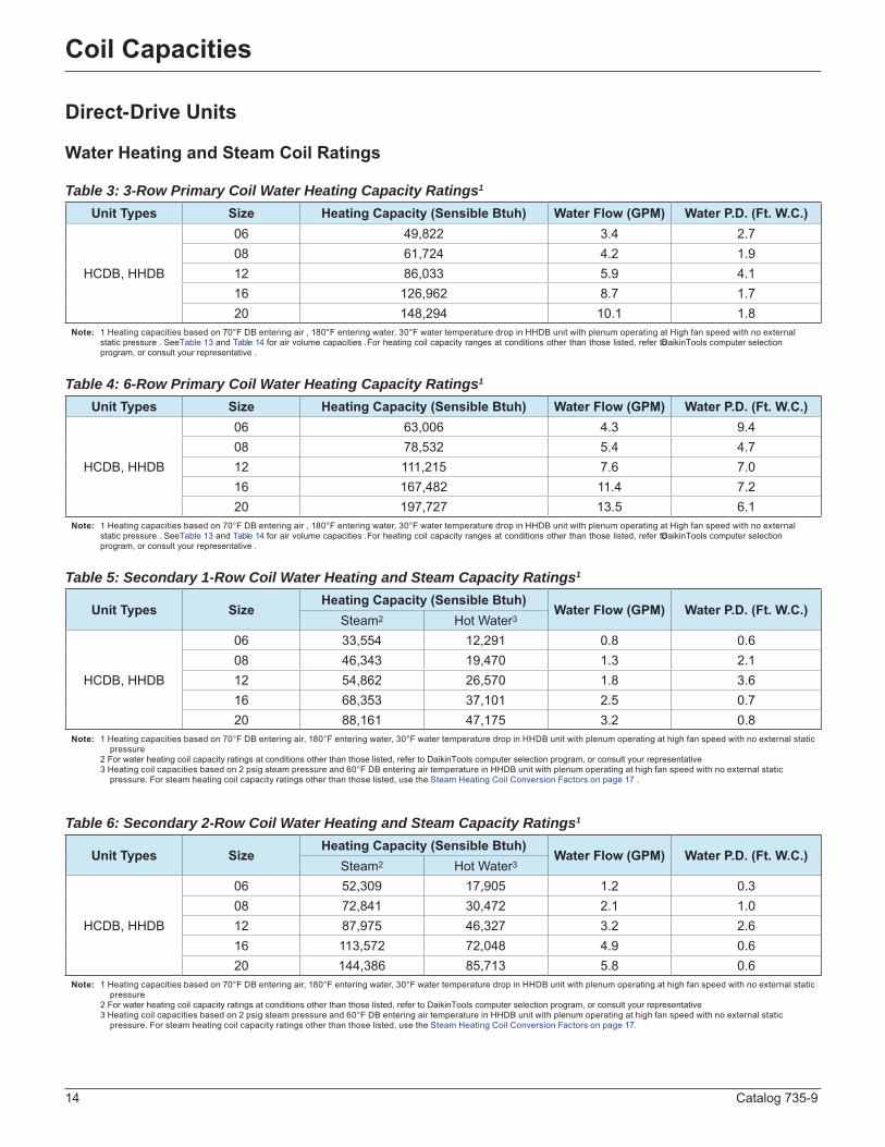
Table 3: 3-Row Primary Coil Water Heating Capacity Ratings1
Table 4: 6-Row Primary Coil Water Heating Capacity Ratings1
Table 5: Secondary 1-Row Coil Water Heating and Steam Capacity Ratings1
Table 6: Secondary 2-Row Coil Water Heating and Steam Capacity Ratings1
Unit Types Size Heating Capacity (Sensible Btuh) Water Flow (GPM) Water P.D. (Ft. W.C.)
HCDB, HHDB
06 49,822 3 .4 2 .708 61,724 4 .2 1 .912 86,033 5 .9 4 .116 126,962 8 .7 1 .720 148,294 10 .1 1 .8
Note: 1 Heating capacities based on 70°F DB entering air , 180°F entering water, 30°F water temperature drop in HHDB unit with plenum operating at High fan speed with no external static pressure . SeeTable 13 and Table 14 for air volume capacities .For heating coil capacity ranges at conditions other than those listed, refer to DaikinTools computer selection program, or consult your representative .
Unit Types Size Heating Capacity (Sensible Btuh) Water Flow (GPM) Water P.D. (Ft. W.C.)
HCDB, HHDB
06 63,006 4 .3 9 .408 78,532 5 .4 4 .712 111,215 7 .6 7 .016 167,482 11 .4 7 .220 197,727 13 .5 6 .1
Note: 1 Heating capacities based on 70°F DB entering air , 180°F entering water, 30°F water temperature drop in HHDB unit with plenum operating at High fan speed with no external static pressure . SeeTable 13 and Table 14 for air volume capacities .For heating coil capacity ranges at conditions other than those listed, refer to DaikinTools computer selection program, or consult your representative .
Unit Types Size Heating Capacity (Sensible Btuh)
Water Flow (GPM) Water P.D. (Ft. W.C.)Steam2 Hot Water3
HCDB, HHDB
06 33,554 12,291 0 .8 0 .608 46,343 19,470 1 .3 2 .112 54,862 26,570 1 .8 3 .616 68,353 37,101 2 .5 0 .720 88,161 47,175 3 .2 0 .8
Note: 1 Heating capacities based on 70°F DB entering air, 180°F entering water, 30°F water temperature drop in HHDB unit with plenum operating at high fan speed with no external static pressure 2 For water heating coil capacity ratings at conditions other than those listed, refer to DaikinTools computer selection program, or consult your representative 3 Heating coil capacities based on 2 psig steam pressure and 60°F DB entering air temperature in HHDB unit with plenum operating at high fan speed with no external static pressure . For steam heating coil capacity ratings other than those listed, use the Steam Heating Coil Conversion Factors on page 17 .
Unit Types Size Heating Capacity (Sensible Btuh)
Water Flow (GPM) Water P.D. (Ft. W.C.)Steam2 Hot Water3
HCDB, HHDB
06 52,309 17,905 1 .2 0 .308 72,841 30,472 2 .1 1 .012 87,975 46,327 3 .2 2 .616 113,572 72,048 4 .9 0 .620 144,386 85,713 5 .8 0 .6
Note: 1 Heating capacities based on 70°F DB entering air, 180°F entering water, 30°F water temperature drop in HHDB unit with plenum operating at high fan speed with no external static pressure 2 For water heating coil capacity ratings at conditions other than those listed, refer to DaikinTools computer selection program, or consult your representative 3 Heating coil capacities based on 2 psig steam pressure and 60°F DB entering air temperature in HHDB unit with plenum operating at high fan speed with no external static pressure . For steam heating coil capacity ratings other than those listed, use the Steam Heating Coil Conversion Factors on page 17 .
Catalog 735-9 15
Coil Capacities
Belt-Drive Units
Water Cooling Coil Ratings
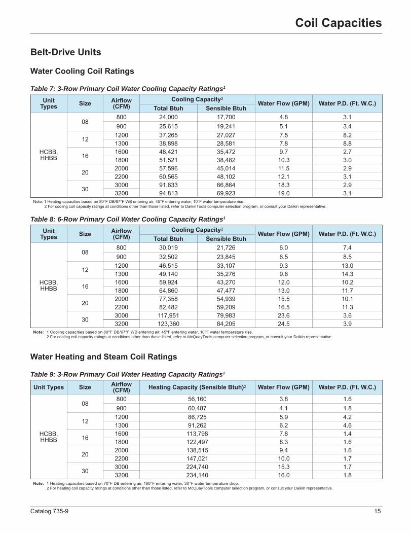
Table 7: 3-Row Primary Coil Water Cooling Capacity Ratings1
Table 8: 6-Row Primary Coil Water Cooling Capacity Ratings1
Water Heating and Steam Coil Ratings
Table 9: 3-Row Primary Coil Water Heating Capacity Ratings1
Unit Types Size Airflow
(CFM) Cooling Capacity2 Water Flow (GPM) Water P.D. (Ft. W.C.)
Total Btuh Sensible Btuh
HCBB, HHBB
08800 24,000 17,700 4 .8 3 .1900 25,615 19,241 5 .1 3 .4
121200 37,265 27,027 7 .5 8 .21300 38,898 28,581 7 .8 8 .8
161600 48,421 35,472 9 .7 2 .71800 51,521 38,482 10 .3 3 .0
202000 57,596 45,014 11 .5 2 .92200 60,565 48,102 12 .1 3 .1
303000 91,633 66,864 18 .3 2 .93200 94,813 69,923 19 .0 3 .1
Note: 1 Heating capacities based on 80°F DB/67°F WB entering air, 45°F entering water, 10°F water temperature rise. 2 For cooling coil capacity ratings at conditions other than those listed, refer to DaikinTools computer selection program, or consult your Daikin representative.
Unit Types Size Airflow
(CFM) Cooling Capacity2 Water Flow (GPM) Water P.D. (Ft. W.C.)
Total Btuh Sensible Btuh
HCBB, HHBB
08800 30,019 21,726 6 .0 7 .4900 32,502 23,845 6 .5 8 .5
121200 46,515 33,107 9 .3 13 .01300 49,140 35,276 9 .8 14 .3
161600 59,924 43,270 12 .0 10 .21800 64,860 47,477 13 .0 11 .7
202000 77,358 54,939 15 .5 10 .12200 82,482 59,209 16 .5 11 .3
303000 117,951 79,983 23 .6 3 .63200 123,360 84,205 24 .5 3 .9
Note: 1 Cooling capacities based on 80ºF DB/67ºF WB entering air, 45ºF entering water, 10ºF water temperature rise . 2 For cooling coil capacity ratings at conditions other than those listed, refer to McQuayTools computer selection program, or consult your Daikin representative .
Unit Types Size Airflow (CFM) Heating Capacity (Sensible Btuh)2 Water Flow (GPM) Water P.D. (Ft. W.C.)
HCBB, HHBB
08800 56,160 3 .8 1 .6900 60,487 4 .1 1 .8
121200 86,725 5 .9 4 .21300 91,262 6 .2 4 .6
161600 113,798 7 .8 1 .41800 122,497 8 .3 1 .6
202000 138,515 9 .4 1 .62200 147,021 10 .0 1 .7
303000 224,740 15 .3 1 .73200 234,140 16 .0 1 .8
Note: 1 Heating capacities based on 70°F DB entering air, 180°F entering water, 30°F water temperature drop . 2 For heating coil capacity ratings at conditions other than those listed, refer to McQuayTools computer selection program, or consult your Daikin representative .

16 Catalog 735-9
Coil Capacities
Belt-Drive Units
Table 10: 6-Row Primary Coil Water Heating Capacity Ratings1
Table 11: Secondary 1-Row Coil Water Heating and Steam Capacity Ratings1
Table 12: Secondary 2-Row Coil Water Heating and Steam Capacity Ratings1
Unit Types Size Airflow(CFM) Heating Capacity (Sensible Btuh)2 Water Flow (GPM) Water P.D. (Ft. W.C.)
HCBB, HHBB
08800 71,080 4 .8 3 .9900 78,229 5 .3 4 .6
121200 115,118 7 .8 7 .41300 123,012 8 .4 8 .3
161600 148,216 10 .1 5 .81800 163,138 11 .1 6 .9
202000 185,494 12 .6 5 .42200 200,542 13 .7 6 .3
303000 275,803 18 .8 1 .93200 290,980 19 .8 2 .0
Note: 1 Heating capacities based on 70°F DB entering air, 180°F entering water, 30°F water temperature drop . 2 For heating coil capacity ratings at conditions other than those listed, refer to McQuayTools computer selection program, or consult your Daikin representative .
Unit Types Size Airflow
(CFM) Cooling Capacity2
Water Flow (GPM) Water P.D. (Ft. W.C.)Steam2 Hot Water3
HCBB, HHBB
08800 44,625 18,741 1 .3 1 .9900 47,290 19,723 1 .3 2 .1
121200 56,878 27,474 1 .9 3 .81300 58,883 28,482 1 .9 4 .0
161600 65,590 35,156 2 .4 0 .61800 68,635 37,110 2 .5 0 .7
202000 87,077 46,313 3 .2 0 .82200 90,486 83,867 5 .7 2 .9
303000 103,113 83,867 5 .7 2 .93200 105,462 86,528 5 .9 3 .0
Note: 1 Heating capacities based on 70°F DB entering air, 180°F entering water, 30°F water temperature drop in HHDB unit with plenum operating at high fan speed with no external static pressure 2 For water heating coil capacity ratings at conditions other than those listed, refer to DaikinTools computer selection program, or consult your representative 3 Heating coil capacities based on 2 psig steam pressure and 60°F DB entering air temperature in HHDB unit with plenum operating at high fan speed with no external static pressure . For steam heating coil capacity ratings other than those listed, use the Steam Heating Coil Conversion Factors on page 17 .
Unit Types Size Airflow
(CFM) Cooling Capacity2
Water Flow (GPM) Water P.D. (Ft. W.C.)Steam2 Hot Water3
HCBB, HHBB
08800 72,807 30,155 2 .1 1 .0900 77,933 32,030 2 .2 1 .1
121200 95,097 49,769 3 .4 3 .01300 99,071 51,949 3 .5 3 .2
161600 111,671 69,869 4 .8 0 .61800 117,834 74,564 5 .1 0 .7
202000 147,770 87,147 5 .9 0 .62200 154,673 91,871 6 .3 0 .7
303000 179,728 155,638 10 .6 1 .53200 184,583 161,498 11 .0 1 .6
Note: 1 Heating capacities based on 70°F DB entering air, 180°F entering water, 30°F water temperature drop in HHDB unit with plenum operating at high fan speed with no external static pressure 2 For water heating coil capacity ratings at conditions other than those listed, refer to DaikinTools computer selection program, or consult your representative 3 Heating coil capacities based on 2 psig steam pressure and 60°F DB entering air temperature in HHDB unit with plenum operating at high fan speed with no external static pressure . For steam heating coil capacity ratings other than those listed, use the Steam Heating Coil Conversion Factors on page 17 .
Note: 1 Heating capacities based on 70°F DB entering air, 180°F entering wate, 30 .°F water temperature drop

Catalog 735-9 17
Coil Capacities
Steam Heating Coil Conversion Factors To determine the capacity conditions other than at 2 PISG steam and 60ºF entering air, multiply the rated capacity by the proper conversion factor below.
Steam Pressure
Steam Temperature (Saturation)
Latent Heat
Conversion Factor for Entering Air Temperature
0ºF 10ºF 20ºF 30ºF 40ºF 50ºF 60ºF 70ºF 80ºF 90ºF
0 212 .0 970 .3 1 .34 1 .27 1 .21 1 .15 1 .08 1 .02 0 .96 0 .90 0 .83 0 .772 218 .5 966 .1 1 .38 1 .31 1 .25 1 .19 1 .13 1 .06 1 .00 0 .94 0 .87 0 .815 227 .1 960 .6 1 .43 1 .37 1 .31 1 .24 1 .18 1 .12 1 .06 0 .99 0 .93 0 .87
10 239 .4 952 .6 1 .51 1 .45 1 .38 1 .32 1 .26 1 .20 1 .13 1 .07 1 .01 0 .9415 249 .7 945 .6 1 .57 1 .51 1 .45 1 .38 1 .32 1 .26 1 .20 1 .13 1 .07 1 .0120 258 .8 939 .6 1 .63 1 .57 1 .51 1 .44 1 .38 1 .32 1 .25 1 .19 1 .13 1 .0625 266 .8 934 .0 1 .68 1 .62 1 .56 1 .50 1 .43 1 .37 1 .31 1 .24 1 .17 1 .12

18 Catalog 735-9
Airflow Capacitie
Direct-Drive Units
Table 13: Air Volume versus External Static Pressure—HHDB Unit without Plenum
Table 14: Air Volume versus External Static Pressure—HCDB & HHDB Unit with Plenum
External Static Pressure (inches H2O)
Air Volume (CFM) for Unit Size
06 08 12 16 20
0 .00High 838 990 1410 2013 2563
Medium 657 810 1170 1811 2300Low 362 479 688 1049 1409
0 .10High 814 963 1339 1944 243
Medium 627 797 1124 1782 2198Low 343 479 662 1042 1364
0 .20High 759 925 1261 1856 2290
Medium 593 775 1062 1719 2081Low 312 471 627 1019 1298
0 .30High 700 882 1175 1761 2129
Medium 554 750 992 1645 1943Low 274 457 584 979 1215
0 .40High 633 832 1081 1653 1943
Medium 507 717 910 1553 1774Low 231 436 530 914 1113
0 .50High 553 769 974 1509 1708
Medium 440 668 802 1406 1560Low 183 402 465 814 992
0 .60High 443 679 846 1285 1390
Medium 340 590 643 1137 1284Low 128 347 387 664 850
Note: Air volumes based on 115V/60Hz/1Ø electrical service, standard water cooling coil (dry coil) and normal unit appurtenances . “High” indicates highest fan speed . “Medium” indicates air volume for medium high (second of four fan speeds) . “Low” indicates lowest fan speed
.
External Static Pressure (inches H2O)
Air Volume (CFM) for Unit Size
06 08 12 16 20
0 .00High 740 930 1185 1910 2232
Medium 640 825 1068 1747 1996Low 365 505 687 1050 1233
0 .10High 697 886 1119 1834 2113
Medium 599 793 1010 1700 1887Low 344 500 651 1040 1176
0 .20High 643 832 1044 1743 1974
Medium 550 751 941 1634 1759Low 312 485 602 1025 1091
0 .30High 582 770 962 1641 1814
Medium 496 702 865 1548 1614Low 274 464 543 989 992
0 .40High 516 702 873 1524 1634
Medium 435 645 786 1437 1453Low 230 433 476 920 885
0 .50High 435 624 776 1379 1429
Medium 361 576 699 1295 1274Low 179 382 399 810 766
0 .60High 325 530 670 1186 1193
Medium 265 485 601 1108 1072Low 119 295 306 655 631
Note: Air volumes based on 115V/60Hz/1Ø electrical service, standard water cooling coil (dry coil) and normal unit appurtenances . “High” indicates highest fan speed . “Medium” indicates air volume for medium high (second of four fan speeds) . “Low” indicates lowest fan speed
.

Catalog 735-9 19
Airflow Capacitie
Belt-Drive Units
Table 15: Pressure Drop through Components
Model CFM
Static Pressure (Inches of Water)
Plenum or Cabinet
Cooling Coil (wet) Heating Coil Grilles Filters
Standard High Capacity 1-Row 2-Row Stamped Double
Deflectio Disposable
08
500 0 .06 0 .18 0 .25 0 .05 0 .10 0 .03 0 .02 0 .09600 0 .09 0 .24 0 .33 0 .07 0 .13 0 .04 0 .03 0 .11700 0 .12 0 .31 0 .42 0 .09 0 .17 0 .05 0 .04 0 .13800 0 .16 0 .38 0 .51 0 .11 0 .22 0 .06 0 .06 0 .15900 0 .20 0 .46 0 .61 0 .13 0 .26 0 .07 0 .07 0 .17
12
800 0 .09 0 .21 0 .30 0 .06 0 .12 0 .03 0 .02 0 .11900 0 .11 0 .26 0 .36 0 .07 0 .14 0 .04 0 .02 0 .131000 0 .14 0 .31 0 .42 0 .09 0 .17 0 .04 0 .03 0 .151100 0 .16 0 .35 0 .48 0 .10 0 .20 0 .05 0 .03 0 .171200 0 .19 0 .41 0 .55 0 .12 0 .23 0 .06 0 .04 0 .191300 0 .23 0 .46 0 .62 0 .13 0 .27 0 .06 0 .05 0 .22
16
1200 0 .10 0 .25 0 .35 0 .07 0 .14 0 .05 0 .03 0 .111300 0 .12 0 .29 0 .39 0 .08 0 .16 0 .05 0 .04 0 .121400 0 .14 0 .32 0 .44 0 .09 0 .18 0 .06 0 .04 0 .131500 0 .16 0 .36 0 .49 0 .10 0 .21 0 .07 0 .05 0 .141600 0 .19 0 .40 0 .54 0 .11 0 .23 0 .07 0 .06 0 .151700 0 .21 0 .44 0 .59 0 .13 0 .25 0 .08 0 .06 0 .161800 0 .24 0 .48 0 .64 0 .14 0 .28 0 .09 0 .07 0 .17
20
1600 0 .17 0 .29 0 .39 0 .08 0 .16 0 .06 0 .06 0 .111700 0 .20 0 .32 0 .43 0 .09 0 .18 0 .07 0 .06 0 .121800 0 .22 0 .34 0 .46 0 .10 0 .19 0 .07 0 .07 0 .131900 0 .24 0 .38 0 .50 0 .11 0 .21 0 .08 0 .08 0 .142000 0 .27 0 .41 0 .54 0 .12 0 .23 0 .09 0 .08 0 .152100 0 .30 0 .44 0 .59 0 .13 0 .25 0 .09 0 .09 0 .16 2200 0 .33 0 .47 0 .63 0 .14 0 .27 0 .10 0 .11 0 .17
30
2000 0 .06 0 .22 0 .30 0 .06 0 .12 0 .04 0 .03 0 .112200 0 .07 0 .25 0 .35 0 .07 0 .14 0 .05 0 .03 0 .132400 0 .09 0 .20 0 .40 0 .08 0 .16 0 .06 0 .04 0 .142600 0 .10 0 .33 0 .45 0 .09 0 .19 0 .06 0 .05 0 .162800 0 .12 0 .37 0 .50 0 .11 0 .21 0 .07 0 .06 0 .173000 0 .14 0 .41 0 .56 0 .12 0 .24 0 .08 0 .07 0 .193200 0 .15 0 .46 0 .61 0 .13 0 .26 0 .09 0 .07 0 .21

20 Catalog 735-9
Airflow Capacitie
Table 16: Fan Performance
Model CFMCoil Face
Velocity (FPM)
RPM and Brake Horsepower for Total Static Pressure (Inches of Water)
¼" ⅜" ½" ⅝" ¾" 1.0" 1-¼" 1-½"RPM BHP RPM BHP RPM BHP RPM BHP RPM BHP RPM BHP RPM BHP RPM BHP
08
500 300 558 0 .080 691 0 .097 798 0 .109 .888 0 .130 970 0 .165 1125 0 .200 1257 0 .243 1381 0 .225600 360 563 0 .090 683 0 .110 790 0 .130 879 0 .150 959 0 .190 1118 0 .215 1250 0 .260 1381 0 .250
700 420 581 0 .100 690 0 .135 792 0 .145 877 0 .170 950 0 .205 1107 0 .262 1238 0 .290 1369 0 .310
800 480 599 0 .110 698 0 .160 793 0 .160 876 0 .190 946 0 .220 1097 0 .310 1226 0 .320 1358 0 .370
900 540 621 0 .125 715 0 .165 803 0 .175 881 0 .205 950 0 .240 1095 0 .375 1220 0 .385 1347 0 .410
12
800 335 589 0 .119 696 0 .145 787 0 .164 875 0 .192 972 0 .227 1127 0 .285 1268 0 .340 1400 0 .415
900 375 606 0 .136 707 0 .162 795 0 .189 881 0 .212 968 0 .247 1118 0 .309 1257 0 .371 1387 0 .445
1000 415 623 0 .153 717 0 .178 803 0 .204 887 0 .231 964 0 .266 1104 0 .333 1245 0 .402 1373 0 .475
1100 460 643 0 .170 733 0 .200 816 0 .228 898 0 .261 972 0 .296 1110 0 .364 1239 0 .432 1363 0 .504
1200 500 663 0 .188 748 0 .222 828 0 .251 909 0 .290 980 0 .325 1111 0 .394 1233 0 .462 1352 0 .532
1300 540 686 0 .219 767 0 .251 834 0 .287 922 0 .326 992 0 .361 1117 0 .409 1236 0 .504 1351 0 .577
16
1200 370 563 0 .180 683 0 .220 790 0 .260 879 0 .300 959 0 .380 1118 0 .430 1250 0 .520 1381 0 .500
1300 400 572 0 .190 686 0 .246 791 0 .276 878 0 .320 952 0 .394 1113 0 .478 1244 0 .550 1375 0 .560
1400 435 581 0 .200 690 0 .270 792 0 .290 877 0 .340 950 0 .410 1107 0 .524 1238 0 .580 1369 0 .620
1500 465 590 0 .210 694 0 .296 792 0 .306 876 0 .360 948 0 .424 1102 0 .572 1232 0 .610 1364 0 .680
1600 495 599 0 .220 698 0 .320 793 0 .320 876 0 .380 946 0 .440 1097 0 .620 1226 0 .640 1358 0 .740
1700 525 610 0 .236 706 0 .326 798 0 .336 878 0 .396 948 0 .460 1096 0 .686 1223 0 .706 1352 0 .780
1800 560 621 0 .250 715 0 .330 803 0 .350 881 0 .410 950 0 .480 1095 0 .750 1220 0 .770 1347 0 .820
20
1600 400 589 0 .238 696 0 .290 787 0 .328 875 0 .384 972 0 .454 1127 0 .570 1268 0 .680 1400 0 .8301700 425 598 0 .256 701 0 .306 791 0 .354 878 0 .404 970 0 .474 1122 0 .594 1263 0 .712 1393 0 .860
1800 450 606 0 .272 707 0 .324 795 0 .378 881 0 .424 968 0 .494 1118 0 .618 1257 0 .742 1387 0 .890
1900 475 615 0 .290 712 0 .340 799 0 .384 884 0 .442 966 0 .512 1114 0 .642 1251 0 .774 1380 0 .920
2000 500 623 0 .306 717 0 .356 803 0 .408 887 0 .462 964 0 .532 1104 0 .666 1245 0 .804 1373 950
2100 525 633 0 .324 725 0 .378 810 0 .432 893 0 .492 968 0 .562 1110 0 .698 1242 0 .832 1368 0 .980
2200 550 643 0 .340 733 0 .400 816 0 .456 898 0 .522 972 0 .592 1110 0 .728 1239 0 .864 1363 1 .008
30
2000 335 507 0 .310 600 0 .360 693 0 .420 773 0 .520 843 0 .600 977 0 .760 1102 0 .940 1217 1 .014
2200 370 518 0 .330 609 0 .400 699 0 .470 771 0 .550 842 0 .630 972 0 .800 1094 0 .960 1205 1 .018
2400 405 529 0 .360 618 0 .440 705 0 .520 770 0 .580 841 0 .660 967 0 .840 1086 0 .980 1194 1 .220
2600 435 543 0 .400 629 0 .480 711 0 .550 776 0 .620 844 0 .710 967 0 .880 1082 1 .036 1188 1 .280
2800 470 558 0 .440 640 0 .520 718 0 .580 782 0 .660 847 0 .760 968 0 .920 1078 1 .090 1182 1 .350
3000 505 574 0 .470 655 0 .560 728 0 .626 791 0 .710 855 0 .810 977 0 .990 1080 1 .156 1179 1 .390
3200 540 591 0 .500 671 0 .600 739 0 .670 800 0 .760 863 0 .860 987 1 .060 1082 1 .220 1176 1 .420

Catalog 735-9 21
Physical and Dimensional Data
HCDB Direct-Drive Cabinet Dimensional Data Right-hand Unit Shown Hand determined by cooling coil connection when facing the discharge .
HHDB Direct-Drive Hideaway Dimensional Data Right-hand Unit Shown Hand determined by cooling coil connection when facing the discharge . NOTE: Unit sizes 16 and 20 have 2 fans
Knockout Dimensions (inches) Unit Size Elec CLG S&R HTG S&R
06, 08 1-3/32 1-1/4 1-1/2 12 1-3/32 1-3/8 1-1/2 16 1-3/32 1-3/8 1-1/2 20 1-3/32 1-3/4 1-3/4
Note: Coil connection knockouts are not necessarily in line with coil connections .
Unit Size
Dimensions (inches)A B C D E F G H J K M N P R S T U V W
06 24 .0 17-5/8 37 .0 20 .0 4 .0 19 .0 44-1/4 18-1/2 14-5/8 2 .0 4-7/16 2-11/16 9-9/16 11-3/8 14-1/4 1-9/16 1-9/16 1-9/16 1 .008 26 .0 17-5/8 46 .0 20 .0 6 .0 21 .0 53-1/4 18-1/2 14-5/8 3 .0 4-7/16 4-7/16 12-1/16 13-7/8 16-3/4 1-9/16 1-9/16 3-3/4 1 .012 33 .0 17-5/8 46 .0 24 .0 8 .0 28 .0 53-1/4 23-1/2 14-5/8 4-1/2 .0 4-7/16 4-7/16 12-1/16 13-7/8 16-3/4 1-9/16 1-9/16 3-3/4 1 .016 44 .0 17-5/8 46 .0 36 .0 8 .0 39 .0 53-1/4 38-1/2 14-5/8 4 .0 4-7/16 2-11/16 8-3/16 13-3/4 16-3/4 2-1/4 2-1/4 2-1/4 1 .020 46 .0 21-1/8 50 .0 41-3/4 6 .0 41 .0 57-1/4 38-1/2 18-5/8 2-1/8 5-1/16 4-1/8 9-7/16 16-1/4 19-1/4 2-1/4 4-3/16 4-3/16 1-1/4
Unit Size Dimensions (inches)A B D E R S U V
06 22 .0 14 .0 14 .0 10-7/8 16-3/8 29-5/8 15-3/4 15-3/808 24 .0 16-1/2 16 .0 13-3/8 18-3/8 29-5/8 15-3/4 15-3/812 31 .0 16-1/2 23 .0 13-3/8 25-3/8 29-5/8 15-3/4 15-3/816 39 .0 16-1/2 31 .0 13-3/8 33-3/8 29-5/8 15-3/4 15-3/820 41 .0 19 .0 33 .0 15-5/8 35-3/8 32-1/8 18-1/4 17-3/8

22 Catalog 735-9
Physical and Dimensional Data
HHDB Coil Connection Locations for Chilled Water Coils Rear View Sizes 06, 08, 12 Rear View Sizes 16, 20
All dimensions approximate. Certified drawings available upon request.
Direct-Drive Physical Data (HCDB / HHDB)
Unit SizeDimensions (inches)
L M N P Q ±⅜ R ±⅜ S ±⅜06 10-7/8 2-3/4 — 4 .0 2-7/8 9-13/16 1-1/1608 13-3/8 2-3/4 — 4 .0 2-7/8 12-5/16 1-1/1612 13-3/8 2-3/4 — 4 .0 2-7/8 12-5/16 1/416 14 .0 1-3/4 3-1/4 8 .0 3-1/16 12-3/8 2 .020 15-1/4 1-3/4* 3-1/4 8 .0 3-1/8 14-5/16 1-5/8
* 1-1/4 for high capacity
Unit Size 06 08 12 16 20Nominal CFM 600 800 1200 1600 2000
Fans (Forwardly Curved — DWDI — Belt-Drive) Number - Diameter 1 - 9” 1 - 9” 1 - 9” 2 - 9” 2 - 9”
Water Connections 1-Row Coil (OD Sw) 7/8 7/8 1-1/8 1-1/8 1-3/82-Row Coil (OD Sw) 7/8 1-1/8 1-1/8 1-3/8 1-3/83-Row Coil (OD Sw) 5/8 7/8 1-1/8 1-1/8 1-1/86-Row Coil (OD Sw) 5/8 7/8 1-1/8 1-1/8 1-5/8
Motors (115V, 60Hz, 1Ø, Permanent Split Capacitor — Direct-Drive)(Number) Nominal
Horsepower (1) 1/4 (1) 1/4 (1) 1/3 (2) 1/4 (2) 1/3
Full Load Amps 3 .5 3 .9 4 .9 7 .8 9 .8Watts (Total) 310 380 480 686 960
RPM 1010 1000 1080 1000 1100Motors (265V, 60Hz, 1Ø, Permanent Split Capacitor — Direct-Drive)
(Number) Nominal Horsepower (1) 1/4 (1) 1/4 (1) 1/3 (2) 1/4 (2) 1/3
Full Load Amps 1 .3 1 .4 2 .0 2 .8 4 .0Watts (Total) 322 350 425 700 850
RPM 1020 1000 1100 1000 1100Filters (Number - Nominal Size)
HCDB Models 1 - 16 × 20 × 2 1 - 16 × 20 × 2 1 - 16 × 25 × 2 2 - 16 × 20 × 2 2 - 20 × 20 × 2HHDB Models 1 - 15-1/2 × 16-1/8 × 2 1 - 15-1/2 × 18 × 2 1 - 15-1/2 × 25 × 2 1 - 15-1/2 × 33 × 2 1 - 18 × 35-1/8 × 2
Shipping Weights (Lbs.)HCDB
with 3-Row Primary Coil 158 191 228 297 387
HCDB with 6-Row Primary Coil 167 203 245 318 512
HHDB with 3-Row Primary Coil 92 98 115 160 180
HHDB with 6-Row Primary Coil 105 110 132 181 208
Water Weight 3-row Coil 7 .2 8 .3 9 .8 21 .0 26 .5Water Weight 6-row Coil 13 .8 22 .0 25 .1 29 .2 55 .5

Catalog 735-9 23
Physical and Dimensional Data
HCBB Belt-Drive Cabinet Dimensional DataRight-hand Unit Shown Hand determined by cooling coil connection when facing the discharge .
HHBB Coil Connection Locations for Chilled Water Coils Rear View Sizes 08, 12 Rear View Sizes 16, 20, 30
All dimensions approximate .
Knockout Dimensions (inches) Unit Size Elec CLG S&R HTG S&R
08 1-3/32 1-1/4 1-1/2 12 1-3/32 1-3/8 1-1/2 16 1-3/32 1-3/8 1-1/2 20 1-3/32 1-3/8 1-3/430 1-3/32 1-3/4 1-3/4
Note: Coil connection knockouts are not necessarily in line with coil connections .
Unit Size
Dimensions (inches)A B C D E F G H J K M N P R S T U V W
08 26 .0 17-5/8 1-1/4 20 .0 6 .0 21 .0 53-1/4 18-1/2 14-5/8 3 .0 4-7/16 4-7/16 12-1/16 13-7/8 16-3/4 1-9/16 1-9/16 3-3/4 1 .012 33 .0 17-5/8 1-1/4 24 .0 8 .0 28 .0 53-1/4 23-1/2 14-5/8 4-1/2 4-7/16 4-7/16 12-1/16 13-7/8 16-3/4 1-9/16 1-9/16 3-3/4 1 .016 44 .0 17-5/8 1-1/4 36 .0 6 .0 39 .0 53-1/4 38-1/2 14-5/8 5 .0 4-7/16 2-11/16 8-3/16 13-7/8 16-3/4 2-1/4 2-1/4 2-1/4 1 .020 46 .0 21-1/8 1-1/4 41-3/4 6 .0 41 .0 57-1/4 38-1/2 18-5/8 2-1/8 5-1/16 4-1/8 9-7/16 16-1/4 19-1/4 2-1/4 2-1/4 4-3/16 1-1/430 62 .0 21-1/8 6-3/4 49-3/4 8 .0 57 .0 57-1/4 48-1/2 18-5/8 6-1/8 5-1/16 2-7/8 9-7/16 16-1/4 19-1/4 2-1/4 2-1/4 4 .0 1-1/4
Unit SizeDimensions (inches)
L M N P Q ±⅜ R ±⅜ S ±⅜08 13-3/8 2-3/4 — 4 .0 2-7/8 12-5/16 11/1612 13-3/8 2-3/4 — 4 .0 2-7/8 12-5/16 1/416 14 .0 1-3/4 — 4 .0 3-1/16 12-3/8 2 .020 15-1/4 1-3/4* 3-1/4 8 .0 3-1/8 14-5/16 1-5/830 16-1/4 4 .0 3-1/4 8 .0 3-1/8 14-5/16 2-1/2
* 1-1/4 for high capacity

24 Catalog 735-9
Physical and Dimensional Data
HHBB Belt-Drive Hideaway with Hanging Rails Dimensional Data Right Hand Unit Shown. Hand determined by cooling coil connection when facing discharge .
HHBB Belt-Drive Hideaway Return and Air Plenum Dimensional Data Right Hand Unit Shown. Hand determined by cooling coil connection when facing discharge .
NOTE: 1 Unit must be supported at all six hanging slots . 2 Return air plenum with 3/4" duct flange is field reversible for back or bottom intake. Add 3-1/2" to “P” dimension for bottom intake .
Unit Size No. of Fans Unit dimensions (in)1 A C D E F J N P Q R
08 1 24 .0 28-1/2 16-1/4 13-3/8 24 .0 21 .0 16-1/2 15-3/4 3 .0 18-1/212 1 31 .0 28-1/2 23 .0 13-3/8 31 .0 28 .0 16-1/2 15-3/4 3 .0 25-1/216 2 39 .0 28-1/2 31 .0 13-3/8 39 .0 36 .0 16-1/2 15-3/4 3 .0 33-1/220 2 41 .0 28-1/2 33-1/4 15-3/8 41 .0 38 .0 18-3/4 18-1/4 3 .0 35-1/230 2 60 .0 30 .0 49 .0 15-3/8 57 .0 54 .0 18-3/4 18-1/4 6 .0 51-1/2
All dimensions approximate .

Catalog 735-9 25
Physical and Dimensional Data
Belt-Drive Physical Data (HCBB/HHBB)
Large Capacity Drive, HP, and Voltage Selection (Factory Installed)
Unit Size 08 12 16 20 30Nominal CFM 800 1200 1600 2000 3000
Fans (Forwardly Curved — DWDI — Belt-Drive) Number - Diameter 1 - 9" 1 - 9" 2 - 9" 2 - 9" 2 - 10"
Water Connections 1-Row Coil (OD Sw) 7/8 1-1/8 1-1/8 1-3/8 1-3/82-Row Coil (OD Sw) 1-1/8 1-1/8 1-3/8 1-3/8 1-3/83-Row Coil (OD Sw) 7/8 1-1/8 1-1/8 1-1/8 1-5/86-Row Coil (OD Sw) 7/8 1-1/8 1-1/8 1-5/8 1-5/8
Filters (Number - Nominal Size)HCBB Models (CZ*) 1 - 16 × 20 × 2 1 - 16 × 25 × 2 2 - 16 × 20 × 2 2 - 20 × 20 × 2 2 - 20 × 25 × 2HHBB Models (HZ*) 1 - 15 1/2 × 18 × 2 1 - 15 1/2 × 25 × 2 1 - 15 1/2 × 33 × 2 1 - 18 × 35 1/8 × 2 1 - 18 × 25 1/2 × 2
Shipping Weights (Lbs.)HCBB with 3-Row Primary Coil 206 233 315 407 512HCBB with 6-Row Primary Coil 218 250 336 435 551HHBB with 3-Row Primary Coil 113 130 178 200 230HHBB with 6-Row Primary Coil 125 147 199 228 268
Water Weight 3-row Coil 7 .2 8 .3 9 .8 21 .0 26 .5Water Weight 6-row Coil 13 .8 22 .0 25 .1 29 .2 55 .5
Unit Size Fan RPM Range Low Motor Horsepower
High Motor Horsepower Voltage Options
08 825 - 1170 0 .33 0 .75 115/208-230/60/1 208-230/460/60/3
12 825 - 1170 0 .50 — 115/208-230/60/1 208-230/460/60/3
12 1030 - 1460 — 0 .75 115/208-230/60/1 208-230/460/60/3
16 590 - 836 0 .50 — 115/208-230/60/1 208-230/460/60/3
16 590 - 836 — 1 .00 115/208-230/60/116 816 - 1110 — 1 .00 208-230/460/60/3
20 690 - 975 0 .75 — 115/208-230/60/1 08-230/460/60/3
20 816 - 1110 — 1 .50 208-230/460/60/320 825 - 1170 — 1 .50 115/208-230/60/130 590 - 836 1 .00 — 115/208-230/460/60/1 30 819 - 1110 1 .00 — 208-230/460/60/330 690 - 975 — 1 .50 115/208-230/60/130 816 - 1110 — 1 .50 208-230/460/60/3
Stock Units Shipped with the Following Drives
Note: 1 Stock unit sizes 08 thru 16 are fitted with drive kits sized for #56 frames 2 Stock unit sizes 20 and 30 are fitted with drive kits sized for 143T/145T frames 3 For applications requiring fan speeds outside the range of factory-provided drives, multiple sheave kits are available for field installation. Contact your Daikin sales representative for more details 4 Other motor voltages (277/60/1, 575/60/3) are available .
Contact your Daikin sales representative for more details
Unit Size Fan RPM Range08 825 - 117012 825 - 117016 825 - 117020 1030 - 146030 965 - 1310

26 Catalog 735-9
Engineering Guide Specification
Part 1: General 1.01 Section Includes
A Large Capacity Fan Coil units.
1.02 References A. AFBMA 9—Load Ratings and Fatigue Life for Ball
Bearings
B. AMCA 99—Standards Handbook
C. AMCA 300—Test Code for Sound Rating Air Moving Devices
D. AMCA 500—Test Methods for Louver, Dampers, and Shutters
E. AG.AHRI 430—Central-Station Air-Handling Units.
F. AHRI 435—Application of Central-Station Air-Handling Units
G. ASTMB117—Standard Practice for Operating Salt Spray Apparatus
H. NEMA MG1—Motors and Generators
I. NFPA 70—National Electrical Code
J. SMACNA—HVAC Duct Construction Standards – Metal and Flexible
K. UL 723—Test for Surface Burning Characteristics of Building Materials
L. UL 900—Test Performance of Air Filter Units
M. UL 1995—Standard for Heating and Cooling Equipment
N. UL 94—Test for Flammability of Plastic Materials for
O. Parts in Devices and Appliances
1.03 Submittals A. Shop Drawings: Indicate assembly, unit
dimensions, weight loading, required clearances, construction details, field connection details, and electrical characteristics and connection requirements. Computer generated fan curves for each air handling unit shall be submitted with specific design operating point noted. A computer generated psychometric chart shall be submitted for each cooling coil with design points and final operating point clearly noted.
B. Product Data:
Provide literature that indicates dimensions, weights, capacities, ratings, fan performance, finishes of materials, and electrical characteristics and connection requirements. Provide data of filter media, filter performance data, filter assembly, and filter frames.
C. Manufacturer’s Installation Instructions.
1.04 Operation and Maintenance Data A. Maintenance Data: Include instructions for
lubrication, filter replacement and motor and drive replacement.
1.05 Qualifi ations A. Manufacturer: Company specializing in
manufacturing the Products specified in this section with minimum five years documented experience, which issues complete catalog data on total product.
1.06 Delivery, Storage, and Handling A. Deliver, store, protect and handle products to site.
B. Accept products on site on factory-installed shipping skids. Inspect for damage.
C. Store in clean dry place and protect from weather and construction traffic. Handle carefully to avoid damage to components, enclosures, and finish.
1.07 Environmental Requirements A. Do not operate units for any purpose, temporary
or permanent, until ductwork is clean, filters are in place, bearings lubricated, and fan has been test run under observation.
Part 2: Products 2.01 Manufacturers
A. The following manufacturers are approved for use. No substitutions will be permitted.
1. Daikin – Large Cap is the basis of design,including standard product features and allspecial features required per plans andspecifications.
2. Trane
3. ETI (JCI)
2.02 Fan Coil Type and Arrangement A. The fan coil shall be furnished as a horizontal
cabinet [hideaway] blow-through cooling coil only [cooling coil and heating coil in reheat position] type.

Catalog 735-9 27
Engineering Guide Specification
2.03 Fan Coil Casing A. Cabinet Type
a. Unit shall be of horizontal console type. Unitpanels shall fabricated of continuous galvanizedsteel exterior finished in Antique Ivory [CupolaWhite] [Off White] [Soft Gray] [Putty Beige][Oxford Brown] [Textured Bronze] paint. Allpanels shall be insulated with 1" neoprene-coated glass fiber.
b. Removable panels on both sides and bottom ofa unit shall provide full access to unit interior.Discharge panel shall be equipped with stampedgrille [double deflection grille] [duct collar].Back panel shall have a 2" filter frame withbottom filter access and be complete with ductcollar.
C. Hideaway Type
a. Unit shall consist of a base casing with [without]return air plenum fabricated of continuousgalvanized steel. Return air plenum shall beinsulated with 1" neoprene-coated glass fiber.Return plenum shall have 2" filter frame forback or bottom return air.
2.04 Supply Fan, Drives, Bearings, and Motors A. Direct-Drive unit.
a. Fan shall be double-width double-inlet (DWDI)forward-curved centrifugal type dynamicallybalanced and directly connected to the motorshaft.
b. Unit shall be equipped with 4-speed direct-drivemotors. Motors shall be 115/60/1 [265/60/1]permanent-split capacitor type with resilientmount, sleeve bearings with oilers and built-in thermal overload protection with automaticreset.
C. Belt-Drive unit
a. The supply fan shall be a DWDI forward-curvedcentrifugal type. Fan assemblies includingfan, motor and sheaves shall be dynamicallybalanced by the manufacturer on all three planesand at all bearing supports. Manufacturer mustensure maximum fan RPM is below the firstcritical speed.
b. Shafts shall be solid, hot rolled steel, groundand polished, keyed to shaft, and protectivelycoated with lubricating oil. Hollow shafts arenot acceptable
c. Bearings and Drives. Bearings to be heavyduty pillow block type, self-aligning, grease-lubricated ball bearings.
d. V-Belt-Drives shall be cast iron or steel sheaves,dynamically balanced, bored to fit shafts andkeyed. Variable and adjustable pitch sheavesselected, so required RPM is obtained withsheaves set at mid-position and rated basedon motor horsepower. Contractor to furnishfixed sheaves at final RPM as determined bybalancing contractor.
e. Motor mount shall be a hinged type for simplebelt tension adjustment and be securely fastenedto the unit. Motor shall be Premium EfficiencyOpen Drip-Proof (ODP) type and mustmeet EPACT minimum efficiency standards(applicable only to 1 HP motors and larger).Electrical characteristics shall be as shown inschedule.
2.05 Electrical and Controls A. Large Capacity Fan Coil power connections and
any control devices shall be field provided.
B. [Opt. Direct-Drive units only] A 2" × 4" junction box shall be furnished by manufacturer for field mount and power connection to the motor.
C. [Opt. Belt-Drive units only] A 4" × 4" junction box with motor wires routed to it shall be furnished by manufacturer for final field mounting and power connection to the motor.
D. [Opt. Direct-Drive Hideaway units only] A 3-speed motor control switch with “Off” position shall be furnished for field wiring to any three of four motor speeds. The speed switch shall be suitable for field installation in a nominal 2" × 4" electrical box by others.

28 Catalog 735-9
Engineering Guide Specification
2.06 Coil Section A. Hydronic Coils:
a. Cooling performance shall be as specified onthe unit schedule
b. Coil tubes shall be ½" seamless copper,expanded into fins, brazed at joints.
c. Aluminum fins shall have full drawn collarsto provide a continuous surface cover over theentire tube for maximum heat transfer. Tubesshall be mechanically expanded into the finsto provide a continuous primary-to-secondarycompression bond over the entire finned lengthfor maximum heat transfer rates. Bare coppertubes shall not be visible between fins.
d. Water coils shall be provided with headers ofseamless copper tubing with intruded tube holesto permit expansion and contraction withoutcreating undue stress or strain. Coil connectionsshall be carbon steel connection size to bedetermined by manufacturer based upon themost efficient coil circuiting.
e. Vent connections shall be provided at thehighest point to assure proper venting. Drainconnections shall be provided at the lowest pointfor proper drainage.
f. Coils shall be tested with 320 pounds airpressure and suitable for 250 psig workingpressure.
g. Coil casings shall be fabricated of galvanizedsteel.
B. Drain Pan
a. Drain pan shall be constructed from continuousgalvanized steel with sloping pitch to primarydrain connection to allow for condensatedrainage insulated with closed-cell insulation.
b. [Opt] Stainless steel drain pan with primary andsecondary drain connections.
2.07 Filters A. Filter section shall be a 2" flat] type furnished with
MERV 3 throwaway type [MERV 8 pleated type] [MERV 13 pleated type] filters
B. Filter media shall be UL 900 listed, Class I or Class II.
Part 3: Execution 3.01 Installation
A. Install in accordance with manufacturer’s Installation & Maintenance instructions.


© 2013 Daikin 02/13
Total system capabilityThinLine™ Fan-coils
Large Capacity Fan-coils
Unit Heaters
HiLine™ Fan-coil
Horizontal
Cabinet
Hideaway
Vertical (Slope Top)
Vertical Unit Heater Horizontal Unit Heater
Daikin Training and Development
Now that you have made an investment in modern, efficient Daikin equipment, its care should be a high priority. For training information on all Daikin HVAC products, please visit us at www .Daiki Applied .com and click on training, or call 540-248-9646and ask for the Training Department .
Warranty
All Daikin equipment is sold pursuant to its standard terms and conditions of sale, including Limited Product Warranty. Consult your local Daikin Representative for warranty details. Refer to Form 933-430285Y. To find your local Daikin Representative, go to www .Daiki Applied .com
Aftermarket Services
To find your local parts office, visit www.DaikinApplied.com or call 800-37PARTS (800-377-2787). To find your local service office, visit www .Daiki Applied .com or call 800-432-1342
This document contains the most current product information as of this printing . For the most up-to-date productinformation, please go to www .DaikinApplied .com
Products Manufactured in an ISO Certified Facilit .
Daikin Applied800.432.1342www.DaikinApplied.com