cast resin distribution transformers - tesla power · immersed distribution transformers, imefy,...
TRANSCRIPT
Cast resin distributiontransformers
Up to 20 MVA | Up to 36 kV
WeTransform energy

02
Cast resin distribution transformers
Cast resin distribution transformers - Introduction

03
IntroductionSince its founding in 1973 as a Company dedicated to the manufacture of liquid immersed distribution transformers, IMEFY, has developed a continuous growth, both technological as expansion, becoming a world leader as a manufacturer of a wide range of transformers, including:•Liquid immersed distribution transformers up to 5000 kVA and 72,5 kV•Power transformers up to 160 MVA and 245 kV•Cast resin transformers up to 20 MVA and 36 kV•Instrument transformers up to 36 kV and 2000 A•IMGS Line, integration service of our transformers in electric rooms, enclosures for
photovoltaic inverters and transformation centers
To this wide range of products, it is joined now transformers designed and manufactured according to the European Regulation n. 548/2014 of the Commission on May 21, 2014 (ECODESIGN), thus offering our customers high-efficiency transformers with low losses according to IMEFY commitment regarding Energy Efficiency, Sustainable Development and Reducing Gas Emissions Greenhouse gas (GHG).
The high standards of quality and reliability of our transformers is one of the hallmarks of IMEFY. This feature, along with the satisfaction and confidence of our customers, and the technological means of the latest generation, have allowed IMEFY develop a global expansion, with our transformers installed all over the world.
To do this, we count on the following Companies which comprise IMEFY GROUP:•IMEFY SPAIN, located in Los Yébenes, as the central headquarters, manufactures
all the range of Transformers •IMEFY ITALY, located in Arezzo, manufactures cast resin Transformers.•IMEFY POLSKA, located in Świebodzice, is the distribution agent and store of
IMEFY products in Eastern Europe. •IMEFY CHILE, located in Santiago de Chile, provides service to the emerging
renewables sector, with the IMGS Line. •EUROMATEL, located in Oporto is the distributor and representative of IMEFY
transformers to cover Portugal and Portuguese-speaking African countries.
All this technology and international coverage allows IMEFY GROUP cover any requirement of customers, being able to adapt our transformers to particular specifications or standards of the country or specific customer.
Cast resin distribution transformers - Introduction
04
Construction featuresThis catalogue describes transformers encapsulated in epoxy resin up to 20MVA and 36kV.(Note: For higher power ratings and insulation series consult IMEFY).
Transformers encapsulated in epoxy resin are a special type of dry transformer (CEI EN 60076-11) with active parts not immersed in insulating liquid.
Where a transformer has one or more encapsulated windings it is commonly known as a transformer encapsulated in resin.
This type of transformer, thanks to advances in manufacturing techniques and the materials used (such as epoxy resin), are being increasingly used due to their high reliability and limited need for maintenance plans, as well as their added value of lesser environmental impact compared to other types of transformer (immersed in dielectric liquids).
Transformers encapsulated in epoxy resin have this name as the M.T. winding is encapsulated in resin, for which impregnation techniques are used, thermal and no-load treatment and a very specific and controlled jellification and polymerisation process which makes possible a fundamental dielectric and mechanical consistency.
An important way of ensuring the quality of M.T. windings is the partial discharge test (individual tests defined in national and international regulations) which concerns both the operational process referred to above and the design know-how.
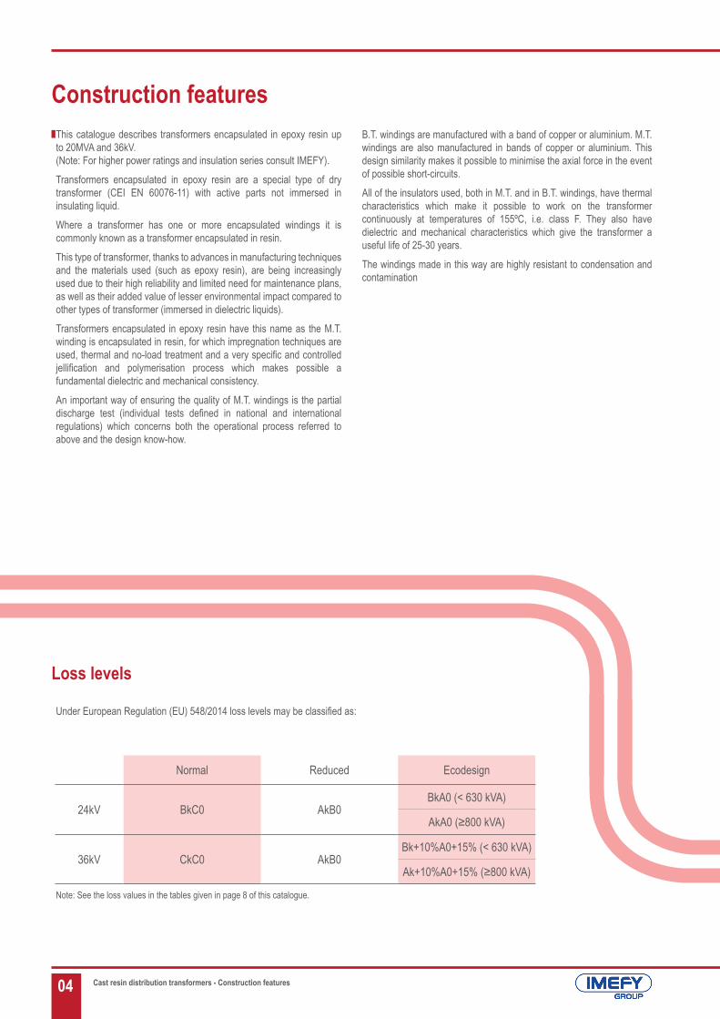
Under European Regulation (EU) 548/2014 loss levels may be classified as:
Cast resin distribution transformers - Construction features
Note: See the loss values in the tables given in page 8 of this catalogue.
Loss levels
Normal Reduced Ecodesign
24kV BkC0 AkB0BkA0 (< 630 kVA)
AkA0 (≥800 kVA)
36kV CkC0 AkB0Bk+10%A0+15% (< 630 kVA)
Ak+10%A0+15% (≥800 kVA)
B.T. windings are manufactured with a band of copper or aluminium. M.T. windings are also manufactured in bands of copper or aluminium. This design similarity makes it possible to minimise the axial force in the event of possible short-circuits.
All of the insulators used, both in M.T. and in B.T. windings, have thermal characteristics which make it possible to work on the transformer continuously at temperatures of 155ºC, i.e. class F. They also have dielectric and mechanical characteristics which give the transformer a useful life of 25-30 years.
The windings made in this way are highly resistant to condensation and contamination

05
The materials used in manufacture exceed the quality controls planned before use in order to ensure the reliability and safety of the final product.
All of this is backed by Quality and Environmental Management Systems in accordance with ISO 9001:2008; ISO 14001:2004 respectively. As a Health and Safety at Work system we are certified by OSHAS 18001:2007.
In addition to these certificates IMEFY transformers are recognised by numerous electrical companies throughout the world, and backed by tests in official independent laboratories such as CESI, KEMA, TECNALIA, LCOE...
Achieving all of these recognitions and certificates over the course of IMEFY’s history has meant important investments in laboratory equipment. Thus IMEFY has ELECTRICAL LABORATORIES with all of the equipment necessary to carry out individual tests on each transformer as defined in rule IEC 60076 as well as all of the type and / or special tests contained in that rule, made on demand and following agreement with the customer.
IMEFY also has a CHEMICAL LABORATORY which makes it possible to carry out the following tests: receiving of material, operational controls of final processes and tests, which without doubt support and demonstrate the quality of the product.
In the same way and in line with regulatory changes (low level of noise emitted by transformers), it also has a recently created ACOUSTIC LABORATORY which thanks to its technology and innovation contributes a reduction of background noise of around 20-25 dB, using absorbent material which covers the walls and ceiling of the inside of the chamber, consisting of a prefabricated glassfibre material with an average sound absorption coefficient of άm=0,84 (Class C).
Cast resin distribution transformers - Construction features

06
The technical committee CENELEC for Transformers Encapsulated in Resin has laid down the minimum requirements for the use of transformers in particularly unfavourable environmental conditions, such as the presence of humidity, industrial and sea pollution and high risk of fire. These documents prepared by CENELEC are contained in the CEI EN 60076-11, including the classifications required and the test procedures for their verification.
The following table sets out the various classifications which underline the above:
All IMEFY transformers are certified: E2-C2-F1 (in accordance with rule CEI 60076-11, Certificate CESI B0005487)
Cast resin distribution transformers - Construction features
Climatic, Environmental and Fire Behaviour Requirements
ENVIROMENTAL CLASSES
E0 There is no condensation in the transformers and contamination is negligible. This is normally achieved in a clean and dry installation interior.
E1 Occasional condensation may occur in the transformer (for example, when the transformer is turned off). Contamination is possible.
E2 Frequent condensation, heavy contamination or a combination of both; with water conductivity in a range between 0,5 s/m and 1,5 s/m.
E3 Close to total condensation, heavy contamination or a combination of both; with water conductivity in a range between 3,6 s/m and 4,0 s/m.
CLIMATIC CLASSES
C1 The transformer is suitable for operation at ambient temperature not below -5ºC but may be exposed during transport and storage to ambient temperatures down to -25ºC.
C2 The transformer is suitable for operation, transport and storage at ambient temperatures down to -25ºC.
FIRE BEHAVIOUR CLASSES
F0 There is no special fire risk to consider. Except for the characteristics inherent in the design of the transformer, no special measures are taken to limit flammability.
F1
•Restricted flammability.•Within a fixed time the fire should auto-extinguish•Minimized emission of toxic substances and opaque smokes.•Materials and combustion products a must be practically extent from halogen composite and give only a
limited thermic energy input at an external fire.
07
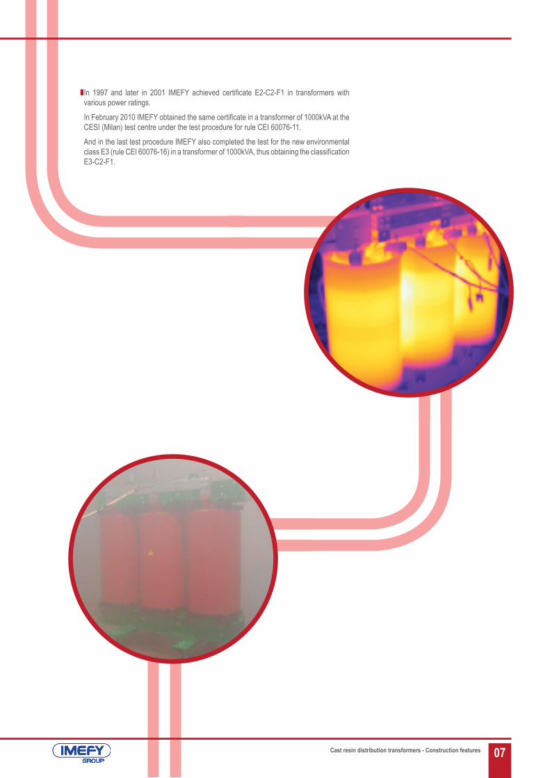
In 1997 and later in 2001 IMEFY achieved certificate E2-C2-F1 in transformers with various power ratings.
In February 2010 IMEFY obtained the same certificate in a transformer of 1000kVA at the CESI (Milan) test centre under the test procedure for rule CEI 60076-11.
And in the last test procedure IMEFY also completed the test for the new environmental class E3 (rule CEI 60076-16) in a transformer of 1000kVA, thus obtaining the classification E3-C2-F1.
Cast resin distribution transformers - Construction features

08
Ecodesign Transformers
Losses table
Due to new trends regarding Legislation, focused on Energy Efficiency and Sustainable Development, IMEFY has created a research team to perform development studies, continuous improvement and energy efficiency of liquid immersed distribution transformers, from the beginning to the end of their useful life.
This R&D team researches and develops mechanism to achieve increasingly efficient products, from:• Raw materials procurement (vegetable oils, high-quality magnetic
steel, etc…)• Processes Development to reduce potential CO³ equivalent
emissions and development of an Energy Plan.• Greater Energy Efficiency throughout the useful life of transformers,
which means an increase of this useful life.• Recycling of materials at the end of life of transformer.
Load Losses and No load Losses (W) Um ≤ 24 kV
Power Load Losses Pk (W) No Load Losses P0 (W) Rated Impedance Voltage (%)Bk Ak C0 B0 A0
100 2050 1800 460 340 280
6
160 2900 2600 650 480 400250 3800 3400 880 650 520400 5500 4500 1200 940 750630 7600 7100 1650 1250 1100800 9400 8000 2000 1500 1300
1000 11000 9000 2300 1800 15501250 13000 11000 2800 2100 18001600 16000 13000 3100 2400 22002000 18000 16000 4000 3000 26002500 23000 19000 5000 3600 31003150 28000 22000 6000 4300 3800
Load Losses and No load Losses (W) Um = 36 kV
PowerLoad Losses Pk (W) No Load Losses P0 (W) Rated Impedance
Voltage (%)Ck Bk Ak C0 B0 A0160 2900 2700 2500 960 900 850
6
250 4000 3800 3500 1280 1100 1000400 5700 5400 5000 1650 1300 1200630 8000 7500 7000 2200 1600 1400800 9600 9000 8400 2700 1900 1650
1000 11500 11000 10000 3100 2250 19001250 14000 13000 12000 3600 2600 22001600 17000 16000 14000 4200 3000 25502000 21000 18500 17000 5000 3500 30002500 25000 22500 20000 5800 4200 35003150 30000 27500 25000 6700 5000 4100
All these studies and investigations, some of them in collaboration with Spanish government, allow IMEFY to offer low-losses transformers according to the European Regulation 548/2014 dated on 21th, May, 2014, which is mandatory from 1st July 2015 for all states of the European Union.
These low losses, which can involve at first an increase in the cost of the transformer due to the special used materials, entail an increased energy efficiency, reduced operating costs and hence in a return on short term investment, according to existing evidence based on mathematical formulas, throughout the lifetime of the transformer.
Cast resin distribution transformers - Ecodesign transformers
NOTE: The ecodesign losses are BkA0 <630kVA y AkA0 ≥800kVA.
NOTE: The ecodesign losses are Bk+10%A0+15% (< 630 kVA) y Ak+10%A0+15% (≥800 kVA).

09
General Drawings
Plans of low tension terminals
See dimensions in page 10 and 11.
Type A B C C CPower I≤400A 400A<I≤1000A 1000A<I≤1600A 1600A<I≤2000A 2000A<I≤3600A
width (b) 30 60 80 100 120 >120
e1 15 14 20 25 30Subject to agreement
between supplier and purchaser
e2 - 32 40 50 60
Nº holes 1 2 4 4 4
Ø holes 14 14 14 14 18
Cast resin distribution transformers - Ecodesign transformers
2W2V2UN
A
BC
1U 1V 1W
1U 1V1W
B
CA
2W2V2UN
A
BC
1U 1V 1W
1U 1V1W
B
C
A
2W2V2UN
AB
C
1U 1V 1W
1U 1V1W
B
C
A
b
e1 e1
e1
A
be1 e2 e1
e1
e2
B
be1 e2 e1
e1
e2
C

10
POWER (kVA)
INSULATION LEVEL (kV)
RATED IMPEDANCE VOLTAGE (%)
LOSSES (W)APPROXIMATE DIMENSIONS (mm) WEIGHTS
(kg)
NOISE LEVEL dB (A) SOUND PRESSURE
Length (A) Width (B) Height (C) 0,3m 1m
10024
6
BkC0 1450 700 1160 800 59 53AkB0 1500 760 1170 1000 51 45BkA0* 1500 760 1230 1050 51 37
36 Bk(+10%)A0(+15%)* 1600 830 1500 1250 51 37
160
24
6
BkC0 1300 740 1170 850 62 56AkB0 1400 760 1280 1100 54 48BkA0* 1400 760 1300 1150 54 40
36CkC0 1500 800 1450 1200 66 60AkB0 1500 800 1500 1300 62 56
Bk(+10%)A0(+15%)* 1700 860 1650 1580 54 40
250
24
6
BkC0 1350 820 1230 950 65 59AkB0 1400 820 1290 1150 57 51BkA0* 1400 820 1350 1200 57 43
36CkC0 1800 930 1550 1800 67 61AkB0 1800 940 1600 2000 64 58
Bk(+10%)A0(+15%)* 1700 940 1650 2050 57 43
31524
6
BkC0 1400 820 1350 1130 67 60AkB0 1500 840 1360 1580 59 52BkA0* 1500 840 1460 1600 58 44
36 Bk(+10%)A0(+15%)* 1800 950 1700 2350 58 44
400
24
6
BkC0 1400 820 1360 1150 68 61AkB0 1500 840 1380 1600 60 53BkA0* 1600 860 1560 1800 60 46
36CkC0 1800 930 1650 2100 69 62AkB0 1900 940 1750 2500 65 58
Bk(+10%)A0(+15%)* 1800 960 1700 2600 60 46
50024
6
BkC0 1450 820 1530 1550 69 62AkB0 1600 850 1550 2010 61 54BkA0* 17100 870 1600 2100 61 47
36 Bk(+10%)A0(+15%)* 1900 980 1800 2900 61 47
630
24
6
BkC0 1500 820 1550 1600 70 63AkB0 1700 870 1570 2200 62 55BkA0* 1700 870 1630 2300 62 48
36CkC0 1800 940 1750 2400 71 64AkB0 1900 950 1850 3050 68 61
Bk(+10%)A0(+15%)* 1900 980 1850 3100 62 48
800 24 6BkC0 1550 820 1650 1850 72 65AkB0 1700 870 1670 2400 64 57AkA0* 1700 890 1700 2600 64 50
Dimensions and weights
Cast resin distribution transformers - Dimensions and weights
(*) Ecodesign

11
POWER (kVA)
INSULATION LEVEL (kV)
RATED IMPEDANCE VOLTAGE (%)
LOSSES (W)APPROXIMATE DIMENSIONS (mm) WEIGHTS
(kg)
NOISE LEVEL dB (A) SOUND PRESSURE
Length (A) Width (B) Height (C) 0,3m 1m
800 36CkC0 1900 960 1900 2800 72 65AkB0 2000 970 1950 3450 69 62
Ak(+10%)A0(+15%)* 1900 990 2000 3500 64 50
1000
24
6
BkC0 1600 820 1760 2200 73 66AkB0 1800 900 1800 3100 65 58AkA0* 1800 900 1900 3200 65 51
36CkC0 2000 960 2000 3200 73 66AkB0 2000 970 2100 3800 70 63
Ak(+10%)A0(+15%)* 2000 1050 2150 4000 65 51
1250
24
6
BkC0 1700 1000 1980 2750 75 67AkB0 1900 1000 2000 3800 67 59AkA0* 1900 1020 2050 3900 67 53
36CkC0 2000 1050 2200 3800 75 67AkB0 2000 1050 2250 4350 72 64
Ak(+10%)A0(+15%)* 2100 1120 2400 4800 67 53
1600
24
6
BkC0 1800 1060 2080 3300 76 68AkB0 2000 1060 2100 4300 68 60AkA0* 2000 1060 2150 4400 68 53
36CkC0 2100 1150 2270 4500 76 68AkB0 2200 1150 23350 5500 73 65
Ak(+10%)A0(+15%)* 2200 1150 2450 5600 68 53
2000
24
6
BkC0 1900 1060 2180 3900 78 70AkB0 2000 1060 2200 4800 70 62AkA0* 2100 1060 2350 5400 70 54
36CkC0 2200 1200 2350 5100 78 70AkB0 2200 1200 2350 5700 74 66
Ak(+10%)A0(+15%)* 2300 1200 2550 6900 70 54
2500
24
6
BkC0 2200 1420 2260 5100 81 73AkB0 2300 1420 2280 6350 71 63AkA0* 2300 1420 2400 7200 71 55
36CkC0 2300 1420 2400 6700 81 73AkB0 2400 1420 2450 7500 78 70
Ak(+10%)A0(+15%)* 2500 1430 2650 8700 71 55
315024
6
BkC0 2300 1420 2390 7200 83 75AkB0 2500 1420 2430 9060 73 65AkA0* 2600 1420 2550 9500 74 58
36 Ak(+10%)A0(+15%)* 2800 1490 2700 11000 74 58
Cast resin distribution transformers - Dimensions and weights
(*) Ecodesign

12
Parts of the transformer
2W2V2UN
1U 1V 1W
2
1
3
6
7
9
5
10
10
1U 1V1W
4
8 11*11*
1 Eye bolt
2 Characteristics plate
3 B.T. terminal
4 Neutral terminal
5 A.T. terminal
6 Tension regulator
7 Pulling device
8 Ground connection
9 Guidable wheels
10 Probes PT-100 connection
11 Forced ventilation (*optional)
1 2 3 4
5
9
6
10
7
11*
8
Cast resin distribution transformers - Transformer parts

13Cast resin distribution transformers - Accessories
Increasing power and voltage is beginning to set a trend for this type of transformer. This means that there is increasing demand for transformers with on-load regulation (normally in cases of transformers of high power rating and high primary voltage) due to the fact that they are being installed in transformation centres which do not allow frequent stops to adjust the fluctuating voltages of the grid. For this type of application the incorporation of an “On-Load Tap-Changer” is needed, which in turn means a specific design of transformer as regulation windings have to be incorporated.
The VACUTAP VT on-load tap-changer is one of the world’s leading oil-free on-load tap-changers, for adjustment of uninterrupted voltage of on-load dry transformers. It is designed as a single-phase module directly assigned to the transformer limb. Having a motorised unit, a single-pole or three-pole 3 x VT I 500 system for star or delta change-over may easily be built.Vacuum interrupters function as load-switching contacts in the VT. The direct assignment of a tap-changer module to the limb of the transformer makes connection easy.
The VACUTAP VT has a maximum through current of 500 A and a maximum step voltage of 900 V for linear voltage adjustment in nine operating positions.With its insulation against ground of Um=40,5kV it can be used in dry transformers for interior installations up to high power levels.Each VT module contains a tap selector and diverter switch for high-speed resistor-type tap change operation in a compact design. The movable tap selector contact system, the diverter switch and the spring-energy accumulator are incorporated in a switching element which is centrally driven by a screw spindle. Vacuum interrupters are used as load-switching contact elements. They guarantee excellent electrical and mechanical properties over an extremely long lifespan. The motor drive unit is supplied as standard and functions in accordance with the step-by-step switching principle in order to mechanically operate the on-load tap-changer. It contains all devices for local and remote control, for remote display of operating positions and the electrical and mechanical end position limits. Its protective housing makes the motor drive unit suitable for outdoor installation, in dry transformers with encapsulated design
Monitoring is the best tool available to you for increasing protection and reducing the risk of breakdown of your transformers.
A monitoring system should be safe, reliable, easy to use and profitable. Our range of control points has all of these characteristics, whether as part of a panel or separately.
Control and Ventilation switchboard: this is a control unit designed to control the temperatures of M.T. transformers, dry or encapsulated in resin, and the feeding of the ventilation system. Its use is recommended in combination with ventilation systems as it is equipped with two ventilation outlets with a maximum capacity of 16A.4 PT 100 entrances allow reading the temperature of 3 windings, and possibly of the core or of the room temperature. There are 2 outlets for controlling the ventilators which provide energy directly to the motors. In this way with a forced ventilation system the transformer can bear power greater than the power rating and maintain an optimal temperature, thus increasing power. The installing of the ventilators in the transformer is helped by the aluminium bar which allows quick and easy assembly.A digital RS485 Modbus outlet can also be fitted as an option.
Control switchboard: this is an electronic device with microprocessor for controlling the temperature of dry M.T. transformers and those encapsulated in resin. The unit provides high levels of protection against electromagnetic fluctuations and is very easy to use. Available for the control of 3 + 1 temperature (three channels for the phases plus an optional fourth for the core or room temperature).
PT 100 probe: a platinum braid gives linear and reliable precision in readings received. Using the best systems various parameters can be monitored: temperature, alarms and ventilation.
In this way with our control switchboards it is possible to monitor the state of the transformer at all times in a safe manner.
On-Load Tap-Changers Thermal monitoring
Control and Ventilation SwitchboardOn-Load Tap-Changers
Control Switchboard
14 Cast resin distribution transformers - IP enclosures
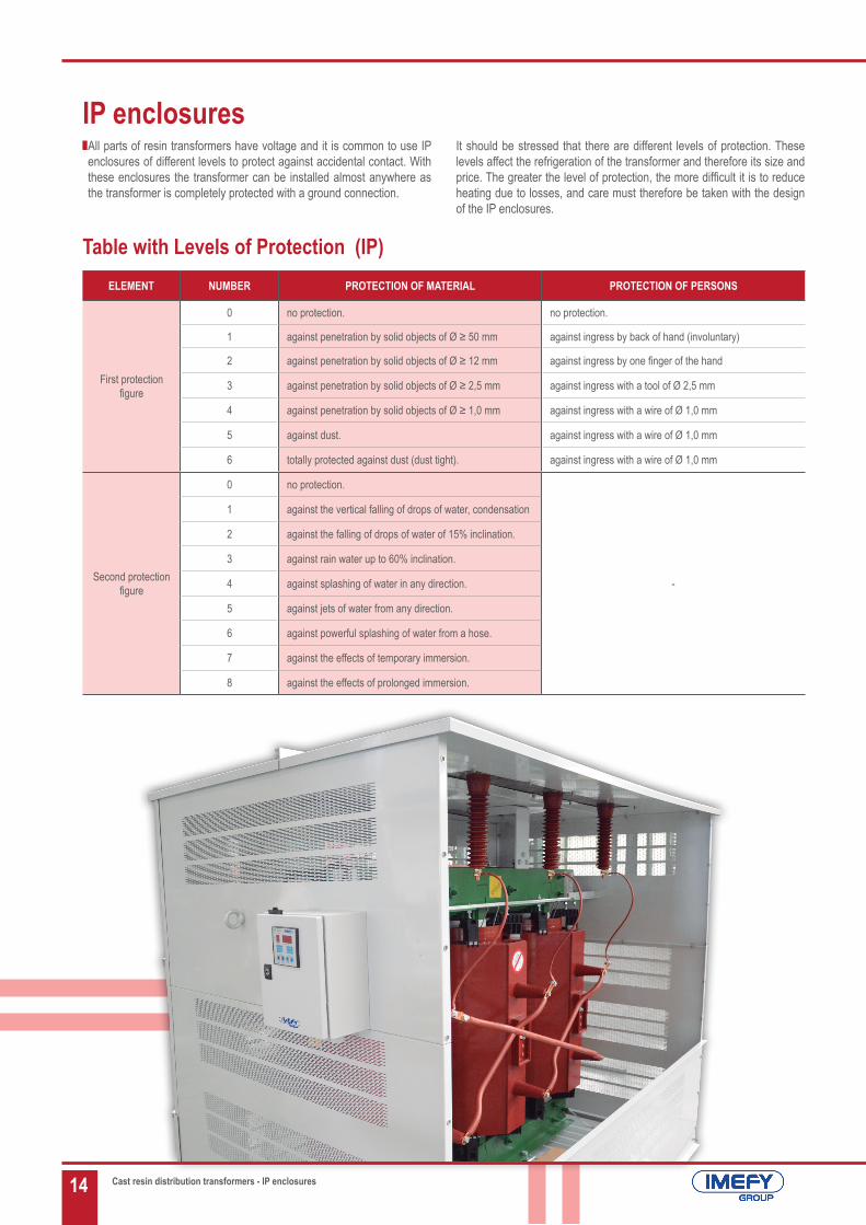
IP enclosuresAll parts of resin transformers have voltage and it is common to use IP enclosures of different levels to protect against accidental contact. With these enclosures the transformer can be installed almost anywhere as the transformer is completely protected with a ground connection.
Table with Levels of Protection (IP)ELEMENT NUMBER PROTECTION OF MATERIAL PROTECTION OF PERSONS
First protectionfigure
0 no protection. no protection.
1 against penetration by solid objects of Ø ≥ 50 mm against ingress by back of hand (involuntary)
2 against penetration by solid objects of Ø ≥ 12 mm against ingress by one finger of the hand
3 against penetration by solid objects of Ø ≥ 2,5 mm against ingress with a tool of Ø 2,5 mm
4 against penetration by solid objects of Ø ≥ 1,0 mm against ingress with a wire of Ø 1,0 mm
5 against dust. against ingress with a wire of Ø 1,0 mm
6 totally protected against dust (dust tight). against ingress with a wire of Ø 1,0 mm
Second protection figure
0 no protection.
-
1 against the vertical falling of drops of water, condensation
2 against the falling of drops of water of 15% inclination.
3 against rain water up to 60% inclination.
4 against splashing of water in any direction.
5 against jets of water from any direction.
6 against powerful splashing of water from a hose.
7 against the effects of temporary immersion.
8 against the effects of prolonged immersion.
It should be stressed that there are different levels of protection. These levels affect the refrigeration of the transformer and therefore its size and price. The greater the level of protection, the more difficult it is to reduce heating due to losses, and care must therefore be taken with the design of the IP enclosures.
15
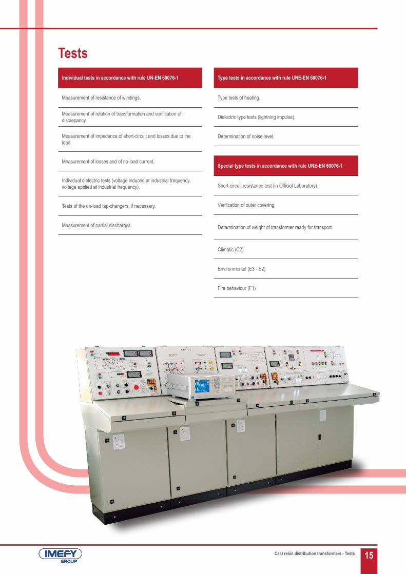
TestsIndividual tests in accordance with rule UN-EN 60076-1
Measurement of resistance of windings.
Measurement of relation of transformation and verification of discrepancy.
Measurement of impedance of short-circuit and losses due to the load.
Measurement of losses and of no-load current.
Individual dielectric tests (voltage induced at industrial frequency, voltage applied at industrial frequency).
Tests of the on-load tap-changers, if necessary.
Measurement of partial discharges.
Type tests in accordance with rule UNE-EN 60076-1
Type tests of heating.
Dielectric type tests (lightning impulse).
Determination of noise level.
Special type tests in accordance with rule UNE-EN 60076-1
Short-circuit resistance test (in Official Laboratory).
Verification of outer covering.
Determination of weight of transformer ready for transport.
Climatic (C2)
Environmental (E3 - E2)
Fire behaviour (F1)
Cast resin distribution transformers - Tests

IMEFY follows a continuous improvement policy, and reserves the right to modify this Handbook without prior notice, not acquiring any responsibilities for it. The content of this catalogue is to provide information, it does not imply any commitment. Please, contact IMEFY for information.
IMEFY CAT_ING_CRT FEBRERO/2016
IMEFY S.L.Transformadores / Transformers
Polígono Industrial “La Cañada”Avenida Siglo XXI s/n
E-45470 Los Yébenes, Toledo (Spain)T.: +(34) 925 32 03 00F.: +(34) 925 32 10 00
www.imefy.com
IMEFY SPATransformatori / Transformers
Zona Industriale Rigutino Ovest, 25952100 - Arezzo (Italy)
T.: +(39) 0575 680701F.: +(39) 0575 657856
www.imefy.it
IMEFY POLSKA Sp. Z.o.o.Transformatory / Transformers
Ul. Wałbrzyska 33, 58 - 160Swiebodzice - Poland
T.: +(48) 74 664 0552F.: +(48) 74 664 5224
www.imefy.com
IMEFY CHILENapoleón 3565, Of. 202
Las Condes,Santiago (Chile)
T.: +(569) 66035512+(34) 677925130
www.imefy.com
EUROMATEL IMEFY GROUPZona Industrial de Aveleda
Rua do Bairro, nº 3254485-010 Aveleda
Vila do Conde - PortugalT.: +(351) 252 637295/6/7
F.: +(351) 252 637290www.euromatel.com
Design: Marketing and Communication Department of IMEFY S.L.