casing isolators/spacers designed specifically for critical … · casing isolators/spacers...
TRANSCRIPT

PSI - a world leader in the design andmanufacture of energy industryproducts.
With over thirty-five years experience indesigning and manufacturing a wide varietyof products for the energy industry, PSI isuniquely positioned to provide a vast knowl-edge base of “real-world” solutions for themost critical of applications located in themost rigorous environments on earth.
Casing Isolators/Spacers designedspecifically for critical energyindustry applications - worldwide.
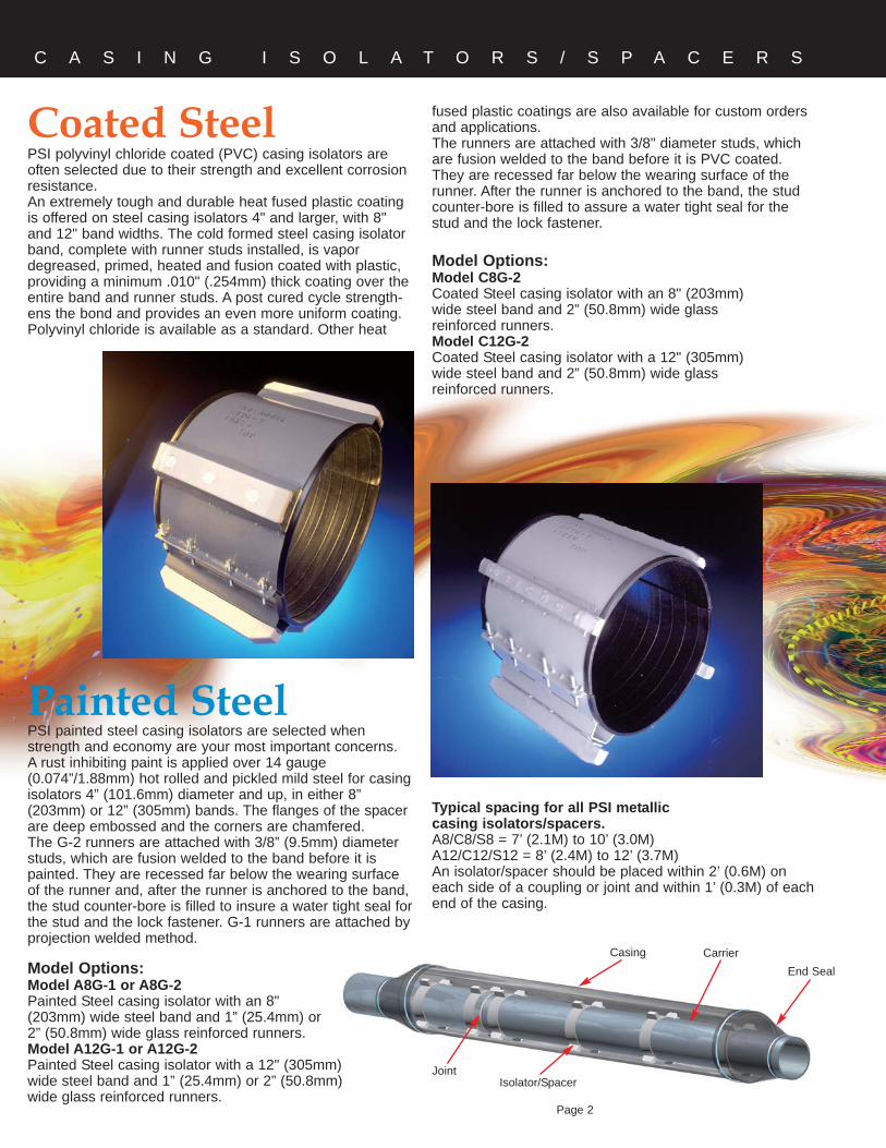
Coated SteelPSI polyvinyl chloride coated (PVC) casing isolators areoften selected due to their strength and excellent corrosionresistance. An extremely tough and durable heat fused plastic coatingis offered on steel casing isolators 4" and larger, with 8"and 12" band widths. The cold formed steel casing isolatorband, complete with runner studs installed, is vapordegreased, primed, heated and fusion coated with plastic,providing a minimum .010" (.254mm) thick coating over theentire band and runner studs. A post cured cycle strength-ens the bond and provides an even more uniform coating.Polyvinyl chloride is available as a standard. Other heat
Painted SteelPSI painted steel casing isolators are selected whenstrength and economy are your most important concerns. A rust inhibiting paint is applied over 14 gauge(0.074”/1.88mm) hot rolled and pickled mild steel for casingisolators 4” (101.6mm) diameter and up, in either 8”(203mm) or 12” (305mm) bands. The flanges of the spacerare deep embossed and the corners are chamfered.The G-2 runners are attached with 3/8” (9.5mm) diameterstuds, which are fusion welded to the band before it ispainted. They are recessed far below the wearing surfaceof the runner and, after the runner is anchored to the band,the stud counter-bore is filled to insure a water tight seal forthe stud and the lock fastener. G-1 runners are attached byprojection welded method.
Model Options:Model A8G-1 or A8G-2Painted Steel casing isolator with an 8" (203mm) wide steel band and 1” (25.4mm) or 2” (50.8mm) wide glass reinforced runners.Model A12G-1 or A12G-2Painted Steel casing isolator with a 12" (305mm) wide steel band and 1” (25.4mm) or 2” (50.8mm) wide glass reinforced runners.
C A S I N G I S O L A T O R S / S P A C E R S
Model Options:Model C8G-2Coated Steel casing isolator with an 8" (203mm)wide steel band and 2” (50.8mm) wide glassreinforced runners.Model C12G-2Coated Steel casing isolator with a 12" (305mm)wide steel band and 2” (50.8mm) wide glassreinforced runners.
fused plastic coatings are also available for custom ordersand applications.The runners are attached with 3/8" diameter studs, whichare fusion welded to the band before it is PVC coated.They are recessed far below the wearing surface of therunner. After the runner is anchored to the band, the studcounter-bore is filled to assure a water tight seal for thestud and the lock fastener.
Typical spacing for all PSI metalliccasing isolators/spacers.A8/C8/S8 = 7’ (2.1M) to 10’ (3.0M)A12/C12/S12 = 8’ (2.4M) to 12’ (3.7M)An isolator/spacer should be placed within 2’ (0.6M) oneach side of a coupling or joint and within 1’ (0.3M) of eachend of the casing.
Page 2
Casing CarrierEnd Seal
Isolator/SpacerJoint

C A S I N G I S O L A T O R S / S P A C E R S
Stainless Steel
Model Options:Model S8G-2Stainless Steel casing isolator with an 8" (203mm) widesteel band and 2” (50.8mm) wide glass reinforced runners.Model S12G-2Stainless Steel casing isolator with a 12" (305mm) widesteel band and 2” (50.8mm) wide glass reinforced runners.
Tough, heavy duty 14 gauge (0.74”/1.88mm) 304 stainlesssteel isolators/spacers are available for use in highlycorrosive environments. They offer maximum corrosionresistance while providing support for large diameter pipe,unusually heavy pipe or for long casing pulls.The flanges of the spacer are deep embossed and thecorners are chamfered.The runners are attached with 3/8” (9.5mm) diameter studs,which are fusion welded to the band. The studs arerecessed far below the wearing surface of the runner and,after the runner is anchored to the band, the stud counter-bore is filled to insure a water tight seal for the stud and thelock fastener.
Runners
Runner material compositions for PSI isolators/spacers areoptimized to insure a smooth, low resistance ride even forthe heaviest and longest pull applications. While providingresistance to the abrasive action, PSI runners areoptimized for maximum compressive strength andhardness.Glass reinforced polymer runners are standard in 1”(25.4mm) or 2” (50.8mm) widths for A (painted).C (coated) and S (stainless steel) models are available in2” (50.8mm) only.PSI glass reinforced runners have 5 times the compressivestrength of polyethylene runners. Our 2” wide runners areparticularly designed for heavier pipes and longer pulls.
Note: For high temperature applications exceeding 400ºF(204ºC), please contact PSI.
Effective Runner Heights and LengthsSizing carrier pipe O.D. and casing I.D. can be mis-leadingat times due to a difference between nominal and effectivedimensions. When sizing, make sure to consider effectiverunner height. Two heights are available/used; custompositioning in the casing can be achieved with riser heights.
Heights - Nominal versus Effective1” and 2” Wide Glass Reinforced Polymer RunnersNominal 1.0” (25.4mm) - 1.5” (38.1mm)Effective 1.07” (27.2mm) - 1.70” (43.2mm)
Lengths - Effective1” Wide Glass Reinforced Polymer Runners8.5” (215.9mm) - 12.5” (317.5mm)2” Wide Glass Reinforced Polymer Runners7.0” (177.8mm) - 11.0” (279.4mm)
Page 3

Ranger II®, All Non-metallic
C A S I N G I S O L A T O R S / S P A C E R S
Model Options:For carrier pipe diameters from 0.83”(21mm) to 37.60” (955mm) in diameter. SeeRanger II literature for runner heights, con-figuration options and ordering information -or visit www.ranger2.com for PDF literatureand installation instructions.
Features• All non-metallic. No nuts, bolts, washers or any other
metal parts to corrode or degrade overtime.
• Segmented pieces - small inventory may beused to accommodate a large variety ofpipe styles, types and diameters. No extratrips from job site to warehouse for addi-tional parts.
• Easy assembly. Simply slide the segmentstogether and ratchet tight with the patented
Band/Runner SegmentsUV resistant polypropylene.
Specifications ValueCompressive Strength 3,000 lbs./sq. in.
(211 kg/sq. cm)Temperature -40°F. to +180ºF.
(-40°C. to +82°C.) Impact Strength 1.5 ft. lb/sq. in.
(10.34kPa)Dielectric Strength 800 Volts/mil. min.Color Black
LinerNone
Typical SpecificationCasing spacers shall be all non-metallic (polypropylene),
molded in segments for field assembly without any specialtools. Spacer segments shall be secured around carrierpipe by insertion of a cinching spline. The casing spacerpolymer shall contain ultraviolet inhibitors and shall have aminimum compressive strength of 3,000 psi, an 800Volts/mil dielectric strength and impact strength of 1.5 ft-lbs./inch. Each casing spacer shall have full length, inte-grally molded skids extending beyond the bell or mechani-cal joint of the carrier pipe.
Each casing spacer shall be manufactured at a facilitythat has a Registered ISO 9001:2000 Quality ManagementSystem. Copy of current ISO 9001:2000 Registration shallbe provided with material submittal.
Approved manufacturer: Pipeline Seal and Insulator, Inc.
An all non-metallic spacer system designed to easecarrier pipe insertion, reduce inventory costs, makeinstallation quick and easy to last for the life of thepiping system.
Slide-Lock connecting system.• Wide variety of runner heights to allow numerous options
for pipe positioning within the casing.• Manufactured from UV resistant polypropylene.• No special tools required for installation.• Accommodates plastic, ductile iron and steel
carrier pipe. (Not suitable for concrete pipe.)
®
TypicalInstallationBased on 20’ (6.1M)carrier pipe segments in a casingof not more than 300’ (91.5M). ConsultPSI for longer casings and for concrete pipe.
Recommended Maximum SpacingAll Ranger II® Isolators/Spacers should not exceed8’ (2.4M) center to center.An isolator/spacer should be placed within 2’(0.6M) on each side of a coupling or joint andwithin 1’ (0.3M) of each end of the casing. Formore details on spacing see Ranger II® brochureat www.pipelineseal.com
Page 4
Casing Carrier
End SealType “S”End Seal(if centered)
Link-Seal®(if centered)
Isolator/Spacer
Joint
Model PE
Model HT
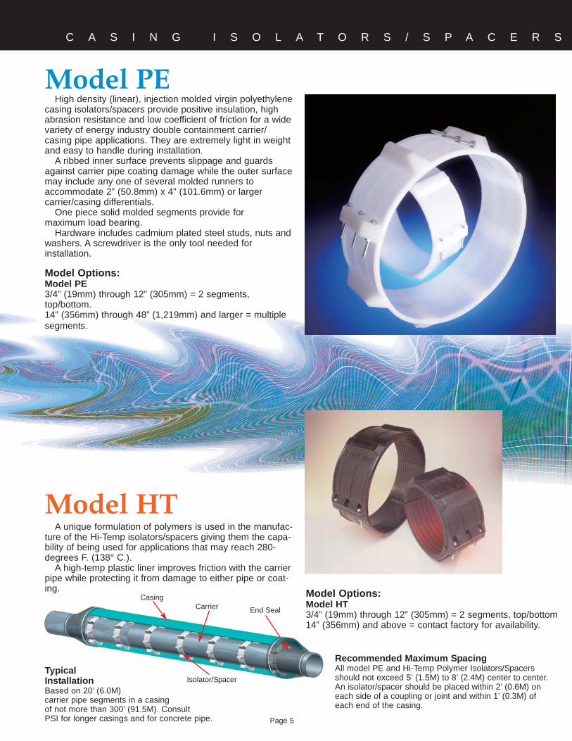
High density (linear), injection molded virgin polyethylenecasing isolators/spacers provide positive insulation, highabrasion resistance and low coefficient of friction for a widevariety of energy industry double containment carrier/casing pipe applications. They are extremely light in weightand easy to handle during installation.
A ribbed inner surface prevents slippage and guardsagainst carrier pipe coating damage while the outer surfacemay include any one of several molded runners toaccommodate 2” (50.8mm) x 4” (101.6mm) or largercarrier/casing differentials.
One piece solid molded segments provide formaximum load bearing.
Hardware includes cadmium plated steel studs, nuts andwashers. A screwdriver is the only tool needed forinstallation.
Model Options:Model PE3/4” (19mm) through 12” (305mm) = 2 segments,top/bottom.14” (356mm) through 48” (1,219mm) and larger = multiplesegments.
A unique formulation of polymers is used in the manufac-ture of the Hi-Temp isolators/spacers giving them the capa-bility of being used for applications that may reach 280-degrees F. (138° C.).
A high-temp plastic liner improves friction with the carrierpipe while protecting it from damage to either pipe or coat-ing.
C A S I N G I S O L A T O R S / S P A C E R S
TypicalInstallationBased on 20’ (6.0M)carrier pipe segments in a casingof not more than 300’ (91.5M). ConsultPSI for longer casings and for concrete pipe.
Recommended Maximum SpacingAll model PE and Hi-Temp Polymer Isolators/Spacersshould not exceed 5’ (1.5M) to 8’ (2.4M) center to center.An isolator/spacer should be placed within 2’ (0.6M) oneach side of a coupling or joint and within 1’ (0.3M) ofeach end of the casing.
Page 5
CasingCarrier End Seal
Isolator/Spacer
Model Options:Model HT3/4” (19mm) through 12” (305mm) = 2 segments, top/bottom14” (356mm) and above = contact factory for availability.

Material SpecificationsMetal Casing Isolators/Spacers
BandPainted & Coated14 Gauge (0.074” [1.88mm]) hot rolled and pickled mild steel. Flanges ofthe spacer are deep embossed and the corners are chamfered.Stainless Steel14 Gauge (0.074” [1.88mm]) 304 stainless steel. Flanges of the spacerare deep embossed and the corners are chamfered.
Configurations4” (101.6mm) through 36” (914mm) = 2 Piece36” (914mm) through 48” (1,219mm) = 3 Piece48” (1,219mm) and over = Consult Factory
Finishes AvailableStainless Steel: NoneCoated Mild Steel: 10 to 16 mil. fusion bonded PVC coating (others available)Painted Mild Steel: Rust inhibiting paint
Fusion Bonded PVC CoatingDurometer - shore A2 (10 sec.) (ASTM D1706-61T) 80Max. Operating Temp. (constant) 150° F. (65° C.)Aging Properties ExcellentElectrical Properties (ASTM D149-61)
(short time .010”) 1,380 V/mil.Resistance:Salt Spray (ASTM B117) ExcellentAcids GoodAlkalies Good
LinerMaterial Polyvinyl ChlorideThickness 0.090” (2.29mm) minimumHardness Durometer “A” 85-90Dielectric Strength
1/8” (3.18mm) Surge Test 60,000 V min.Step-by-step Test 58,000 V min.
Water Absorption 1% max.
RisersStainless Steel10 gauge (0.135mm) 304 stainless steel MIG welded to band.Coated & Painted Mild Steel10 gauge (0.135mm) steel MIG welded to band.
Runners (see page 3 for effective dimensions)Sizes and ConfigurationsStainless Steel & Coated - 2” (51mm) Wide Glass ReinforcedPolymer RunnersPainted - 1” (25.4mm) or 2” (51mm) Wide Glass ReinforcedPolymer Runners4” (101.6mm) thru 12” (305mm) = 2 top & 2 bottom14” (356mm) thru 36” (914mm) = 2 top & 4 bottom
Runner SpecificationsTensile Strength, (ASTM D638) 17,600 psi 1,237 kg/cm2
Flexural Strength, (ASTM D790) 25,300 psi 1,779 kg/cm2
Compression Strength, (ASTM D695) 18,000 psi 1,266 kg/cm2
(10% Deformation)Deflection Temp. @ 264 psi - (ASTM D648) 405°F (205°C)Deformation Under Load: @ 122°F (50°C) 2000 lb. load - (ASTM D621) 1.2%
Studs, Nuts and WashersStuds = 5/16” - 18 x 2 1/2” 304 stainless steel or platedHex Nuts = 5/16”Washers = 5/16” SAE 2330Configurations8” (203.2mm) Band = 6 studs, 12 nuts and washers12” (305mm) Band = 8 studs, 16 nuts and washers
Material SpecificationsModel PE Plastic Casing Isolators/Spacers
Band/Runner SegmentsModel PEInjection molded virgin polyethylene.
Specifications ASTM Test ValueTensile Strength D638, D651 3,100 - 5,500 psi
218 - 387 kg/cm2
Compressive Strength D693 3,200psi (225kg/cm2)Water Absorption D570 0.1%Temperature 180º F. Max. (82º C.)Impact Strength D256 1.5 - 2.0 ft. lb/in.
(0.8 -1.07 newton-meter/cm)
Dielectric Strength D149 450 Volts/mil.Color Natural
LinerNone
RunnersSizes and Configurations3/4” (19mm) through 12” (305mm) = 2-piece with molded-in runners.14” (356mm) and larger = Multiple segments with molded-in runners.
HardwareMetallic Bolts and Square Nuts = Plated SteelNon-metallicBolts and Nuts = High Temp Plastic
NoteModel PE Casing Isolators/Spacers are designed primarily for smallerdiameter steel or polyethylene carrier pipes (ANSI O.D. pipe without a bellor mechanical joint). We do not recommend that they be used on any car-rier pipe over 24” (610mm) in diameter or for installation over 200 feet(61M) long without consulting with PSI. PE isolators/spacers should notbe used on concrete carrier pipe.
Typical SpecificationCasing isolators/spacers shall be PSI Model PE molded from high densitypolyethylene plastic in two segments. Each spacer segment shall be asolid, non-welded molded piece designed for accommodating specific sizepipe O.D.’s.Each casing spacer shall be manufactured at a facility that has aRegistered ISO 9001:2000 Quality Management System. Copy of currentISO 9001:2000 registration shall be provided with material submittal.Approved manufacturer: Pipeline Seal and Insulator, Inc.For 3/4” (19mm) through 12” (305mm) nominal diameter carrier pipe use2-piece model PE. For 14” (356mm) and larger nominal diameter carrierpipe, use multi-segment Model PE.
How to Order Plastic Casing Isolators/Spacers1. Quantity2. Model Number3. Carrier Pipe O.D.4. Coating Thickness5. Casing O.D. andWall Thickness6. Contact your localdistributor or PipelineSeal and Insulator, Inc.
C A S I N G I S O L A T O R S / S P A C E R S
2-Piece(for 3/4” to 12”)
Multi-segment(for 14” and above)
Page 6 Note: For higher temperature applications not published contact PSI.

How to Order Metal Casing Isolators/Spacers1. Quantity2. Type Finish3. Band Width4. Runner Width5. Carrier Pipe O.D. (Type and coating thickness if applicable)6. Casing Pipe I.D. (Type and coating thickness if applicable).7. Carrier Pipe Joint O.D. 8. Carrier pipe position within casing9. Length of crossing10. Contact your local distributor or Pipeline Seal andInsulator, Inc.
G-2 GlassReinforcedPolyesterRunner
Minimum 1”clearance
typical.
G-2 GlassReinforcedPolyesterRunner
Sizes 14” thru 36”(Consult factory for larger
sizes)
Sizes 4” thru 12”
Type FinishA = PaintedC = CoatedS = 304 Stainless Steel
Band Width8 = 8” Band12 = 12” Band
Runner WidthG-1 = 1” Wide Glass Reinforced Runners*G-2 = 2” Wide Glass Reinforced Runners
Carrier Pipe O.D.Indicate actual O.D. including coating.
Casing Pipe I.D.Indicate actual I.D. including coating.
Carrier Pipe Joint O.D. (if applicable)Indicate actual O.D. including coating.
Position within CasingS = StandardC = Centered
* = G-1 Runners Available on Painted Models Only.C 12 G-2 16.00 x 23.25 - (none) S
C A S I N G I S O L A T O R S / S P A C E R S
Factory made casing isolators/spacers of the following descrip-tion shall be installed on any carrier pipe passing through a pipecasing. They are designed to protect the carrier pipe corrosioncoating and electrically isolate the carrier pipe from the casing.Typical Steel Casing Isolator/Spacer Specification
Casing Isolators/spacers shall be PSI Model C8G-2 for carrierpipes up to 24-inch diameters and Model C12G-2 for larger pipesizes as manufactured by Pipeline Seal and Insulator, Inc.,Houston, TX.
Casing isolators/spacers shall have a minimum 14 gauge steelband and where required, 10 gauge risers. The band, risers andconnecting studs shall be welded and cleaned at the factorybefore the application of a fluidized bed fusion bonded PVC coat-ing of between 10-16 mils thickness. The PVC coating shall pro-vide good resistance to acids and alkalies and excellent resist-
ExampleCoated 12” (305mm) wide steel band casing spacer with 2”(50.8mm) wide glass reinforced polymer runners for a 16”(400mm) steel pipe with a 16.00” (400mm) outside diameterwithin a casing pipe with a 23.25” (590mm) inside diameter,standard position.
Standard
Centered
ance under ASTM B117 salt spray tests. (Epoxy coatings are notan acceptable alternative).
The isolators/spacers shall have a flexible PVC inner liner of0.09 inch thickness with a durometer “A” 85-90 hardness and aminimum 58,000 volt dielectric strength.
The runners shall be high pressure molded glass reinforcedpolymer with a minimum compressive strength of 18,000 psi perASTM D638. The runners shall be 2.0 inch in width and a mini-mum of 7.0 inches long for C8G-2 models and 11” for C12G-2models (polyethylene runners are not an acceptable alternative).The runners shall be attached to the band or riser by 3/8” weldedsteel studs and lock nuts which shall be recessed far below thewearing surface on the runner. The recess shall be filled with acorrosion inhibiting filler. The band section shall be bolted togetherwith cadmium plated studs, nuts and washers.
Quality AssuranceEach isolator/spacer shall be manufactured at a facility that has
a Registered ISO 9001:2000 Quality Management System. Copyof current ISO 9001:2000 registration shall be provided with
material submittal.Considerations
The above specification is considered sufficientfor most pipe sizes and types up to 36-inchesand casing lengths up to 300 feet. For largersize pipes or longer or unusual casings, pleasecontact Pipeline Seal and Insulator, Inc. Forhigher temperature applications not published,please contact Pipeline Seal and Insulator, Inc.
Page 7
Minimum 1”clearance
typical
WarrantyAll products are warranted against failure
caused by manufacturing defects for a period ofone year. Any product found to be so defective and
returned within one year from date of shipment will bereplaced without charge. The above warranty is made inlieu of, and we disclaim, any and all other warranties,expressed or implied, including the warranties of mer-chantability and fitness for a particular purpose, and buyeragrees to accept the products without any such warranties.We hereby disclaim any obligation or liability for conse-quential damages, labor costs or any other claims or liabili-ties of any kind whatsoever.
Pipeline Seal and Insulator, Inc.6525 Goforth Street, Houston, TX 77021 U.S.A.Telephone: 713-747-6948, Fax: 713-747-6029Toll Free: 800-423-2410www.pipelineseal.com, e-mail: [email protected]
©2007, Pipeline Seal and Insulator, Inc.PSI-E3/07
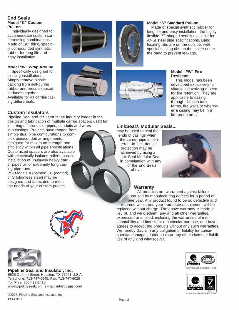
End SealsModel “C” CustomPull-on
Individually designed toaccommodate custom car-rier/casing combinations.Made of 1/8” thick, special-ly compounded syntheticrubber for long life andeasy installation.
Model “W” Wrap AroundSpecifically designed for
existing installations.Simply remove plasticbacking from self-curingrubber and press exposedsurfaces together.Available for all carrier/cas-ing differentials.
Custom InsulatorsPipeline Seal and Insulator is the industry leader in thedesign and fabrication of multiple carrier spacers used forinserting different size pipes, conduits and wiresinto casings. Projects have ranged fromsimple dual pipe configurations to com-plex pipe/conduit arrangements,designed for maximum strength andefficiency within all pipe specifications. Customized spacers are also availablewith electrically isolated rollers to easeinstallation of unusually heavy carri-er pipes or for extremely long cas-ing pipe runs.PSI Models A (painted), C (coated)or S (stainless steel) may bedesigned and fabricated to meetthe needs of your custom project.
Model “S” Standard Pull-onMade of special synthetic rubber for
long life and easy installation, the highlyflexible “S”-shaped seal is available forANSI steel pipe specifications. Bandlocating ribs are on the outside, withspecial sealing ribs on the inside underthe band to prevent leakage.
Model “FW” FireResistant
This model has beendeveloped exclusively forsituations involving a needfor fire retention. They areapplicable to casingthrough dikes in tankfarms, fire walls or wherev-er a casing may be in afire prone area.
Page 8
LinkSeal® Modular Seals...may be used to seal theends of casings whenthe carrier pipe is cen-tered. In fact, doubleprotection may beachieved by using aLink-Seal Modular Sealin combination with any
of the End Sealsabove.