casing design
DESCRIPTION
N/ATRANSCRIPT

Casing Design
• What casing size?
– Set by Pump, Packer, Tubing Requirements and Limited by meeting pressure and economic objectives.
• Where is the largest tubing? The casing has to accommodate the tubing.
• Are kickoffs planned? – what size tubular is in the kickoff?
• What about pump and other equipment needs – and sizes….
• How many casing strings are needed to make depth?
• A casing string is designed from the bottom to the top and from the inside to the outside.
8/25/2015
George E. King Engineering GEKEngineering.com
1

Slim Hole Wells
• Slim hole wells are often drilled and completed to try to meet economic goals.
• From completion, stimulation, reliability, lift and workover considerations, a slim hole well is often the very worst choice.
• Choose wisely!
8/25/2015 George E. King Engineering
GEKEngineering.com 2

Casing Design Example
• Simple hand-worked design using collapse, burst and tensile in the design.
• First example – a multiple weight/grade pick to show where strength is required – avoid this design in the real world if possible.
• Second – calculation of a single pipe weight and grade that can be used.
NOTE - This example problem is not intended to teach casing design, nor is it a replacement for modern casing design methods. More modern equations (e.g., API equations) are available as are a variety of computer simulations that are much more accurate that this approximation. 8/25/2015 3
George E. King Engineering GEKEngineering.com

Buoyancy – brine offsets part of all of the pipe weight
Wb = Wa (1 – rf / rs)
Wb = buoyed weight of casing in a fluid
Wa = air weight of casing
rf = density of fluid, lb/gal
rs = density of steel = 65 lb/gal
8/25/2015 4 George E. King Engineering
GEKEngineering.com

Simple Buoyancy Example
• 10,000 ft string, 7”, 26 lb/ft, 12 lb/gal mud
• Wair = (10,000 ft) (26 lb/ft) = 260,000 lb
• Wbuoyed = (260,000 lb) (1- (12/65.4)) = = 212,294 lb
• For larger pipe strings and heavier brine, the effect of buoyancy is increased. Very large pipe in heavy brine can actually float.
8/25/2015 5 George E. King Engineering
GEKEngineering.com

Calculated Hook Load Changes
8/25/2015 George E. King Engineering
GEKEngineering.com 6
Mud in Hole Mud in Csg 212,300 lb
Mud in Hole Cmt in Csg 283,600 lb
Cmt in Hole Cmt in Csg 195,600 lb
Cmt in Hole Water in Csg 65,936 lb
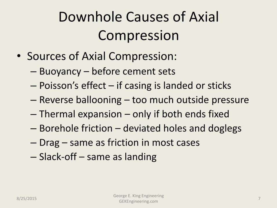
Downhole Causes of Axial Compression
• Sources of Axial Compression: – Buoyancy – before cement sets
– Poisson’s effect – if casing is landed or sticks
– Reverse ballooning – too much outside pressure
– Thermal expansion – only if both ends fixed
– Borehole friction – deviated holes and doglegs
– Drag – same as friction in most cases
– Slack-off – same as landing
8/25/2015 7 George E. King Engineering
GEKEngineering.com

Axial (Tensile) Force versus Depth in a Casing String
• 12,000 ft, 9-5/8”, 53.5 lb/ft casing (0.545 wall), suspended in 16 lb/gal mud.
• Wa = (12,000 ft) (53.5 lb/ft) = 642,000 lb
• Wbuoyed = (642,000 lb) (1- (16/65.4)) =484,935 lb
• Buoyancy force = 642,000 – 484,935 = 157.065 lb
8/25/2015 8 George E. King Engineering
GEKEngineering.com

Wa
Wb
- 0 +
Wt on pipe at depth
Surface
Weight
Buoyancy
Neutral point is a calculated position on the pipe that shows offset of string weight by buoyancy.
8/25/2015 9 George E. King Engineering
GEKEngineering.com
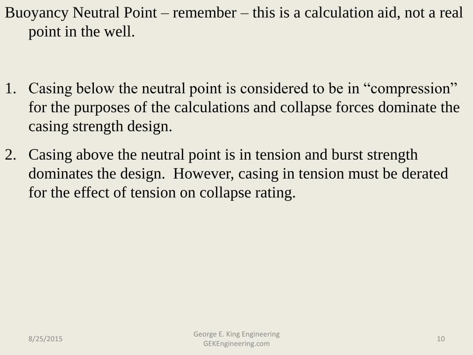
Buoyancy Neutral Point – remember – this is a calculation aid, not a real
point in the well.
1. Casing below the neutral point is considered to be in “compression”
for the purposes of the calculations and collapse forces dominate the
casing strength design.
2. Casing above the neutral point is in tension and burst strength
dominates the design. However, casing in tension must be derated
for the effect of tension on collapse rating.
8/25/2015 10 George E. King Engineering
GEKEngineering.com

Collapse Design – Be careful, this type of
design considers only initial, static froces
and does not consider dynamic, production
and thermal forces
Pcx = 0.052 rf Dx
Pcx = collapse pressure exerted by the mud at a depth Dx
rf = density of mud, lb/gal
Dx = depth
With this formula a collapse pressure at an estimated depth is calculated
(safety factor has not been applied yet).
8/25/2015 11 George E. King Engineering
GEKEngineering.com

Casing Design Example – Note – this is the old
method that uses multiple picks of string weight and
grade – it is useful for showing how a simple design
works, but many pipe grades and weights would create
confusion at the well during casing running.
Design a 10,000 ft string of 7” casing.
Pore pressure = 8000 psi at 10,000 ft.
Mud weight = 16.3 lb/gal.
Frac gradient = 0.9 psi/ft.
Convert to gradients:
Pore pressure = 8000/10,000 = 0.8 psi/ft
Mud weight = 16.3 lb/gal * (0.052) = 0.85 psi/ft
Frac gradient = 0.9 psi/ft 8/25/2015 12
George E. King Engineering GEKEngineering.com

Calculate the “Theoretical” Buoyancy Neutral Point.
N.P. = Dx (1- (fluid density/steel density)
= 10,000 ft (1 – (16.3/65.4)
= 7500 ft
This is the equivalent amount of the string weight at the
surface. If a heavier fluid was used, the N.P. would be
shallower in the well (more of the pipe weight would be
offset by the buoyancy).
8/25/2015 13 George E. King Engineering
GEKEngineering.com

Maximum Collapse Force
Pcx = (10000 ft) * (0.85 psi/ft) = 8500 psi
Since it is a force and not a rating, the safety factor is multiplied:
Pcx = (8500) * (1.1) = 9350 psi
Now, select a pipe with a collapse pressure minimum that will handle
the load…. No need to derate the pipe number, the safety factor has
already been applied on the force (or load).
First pick… 7”, 32 lb/ft, C-95, Pc = 9730 psi.
This is the bottom joint – there is less strength required as the
strength analysis comes up the well – until it nears the top. The
strength required is maximum at the bottom (collapse is maximum)
and at the top (burst is maximum).
Although this method would lead to many different weights and
grades, the best approach is a single selection of strong casing. 8/25/2015 14
George E. King Engineering GEKEngineering.com
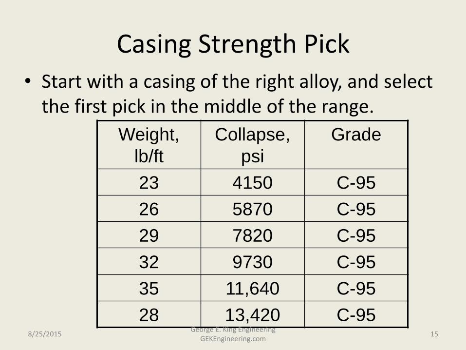
Casing Strength Pick • Start with a casing of the right alloy, and select
the first pick in the middle of the range.
Weight,
lb/ft
Collapse,
psi
Grade
23 4150 C-95
26 5870 C-95
29 7820 C-95
32 9730 C-95
35 11,640 C-95
28 13,420 C-95 8/25/2015 15
George E. King Engineering GEKEngineering.com
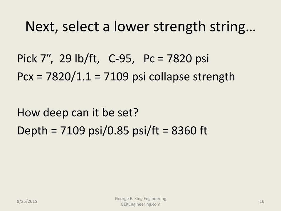
Next, select a lower strength string…
Pick 7”, 29 lb/ft, C-95, Pc = 7820 psi
Pcx = 7820/1.1 = 7109 psi collapse strength
How deep can it be set?
Depth = 7109 psi/0.85 psi/ft = 8360 ft
8/25/2015 16 George E. King Engineering
GEKEngineering.com

Set Point – for the 32 lb/ft top
• The bottom of the 29 lb/ft sets the top of the 32 lb/ft. Note – the 32 lb/ft string can be run higher but the 29lb/ft is theoretically cheaper and lighter.
• The 32 lb/ft runs from 8360 to 10,000 ft.
8/25/2015 17 George E. King Engineering
GEKEngineering.com
Select a third string…..
7”, 26 lb/ft, C-95, Pc = 5870 psi Safety factor = 1.1, Pcx = 5870/1.1 = 5330 psi Set depth = 5330/0.85 = 6270 ft Neutral Point = 7500 ft – since this depth is above the
N.P., the calculations switch to burst design rather than collapse design.
Deration of the collapse for tension effects is common – use 4% deration as a starting point, but the final effect is usually between 1% and 2% except in extreme cases.
8/25/2015 18
George E. King Engineering GEKEngineering.com

Effect of axial loads on collapse and burst
Casing in tension is weaker
in collapse and stronger in
burst – consider it for
collapse calculations.
Casing in compression is
weaker in burst and stronger
in collapse – ignore it for
collapse calculations.
8/25/2015 19 George E. King Engineering
GEKEngineering.com

Derate for collapse:
1. Derate maximum depth by 4% (this is an experience estimate, the
correct value is usually between 2% and 4%).
2. Calculate unit tensile stress:
St = (7500 ft – 6020 ft) * 26 lb/ft = 38480 lb
3. Axial load factor = (unit tensile stress/tensile body strength)
= (38480 / 717,000) = 0.054
4. Derating factor (from deration tables for casing) = 0.985
5. Pc = (5330 psi)(0.985) = 5280 psi
6. Collapse check = (5250 / 0.85) = 6176 ft,
first guess of 6020 ft is OK.
8/25/2015 20 George E. King Engineering
GEKEngineering.com

Design to this point:
Interval Weight Grade
10,000’ to 8360’ 32 lb/ft C-95
8360’ to 6020’ 29 lb/ft C-95
6020’ to ? 26 lb/ft C-95
Since the depth is now above the buoyancy neutral point, burst becomes
the basis for design. 8/25/2015 21
George E. King Engineering GEKEngineering.com

Safety Factors
Safety factors used in the calculations vary with the application. The following as general estimates for this example. Safety factors must be set by engineering experts well versed in your application.
• For this problem: – Collapse – risk: lose a section of the well, safety factor of
1.1 is typical.
– Burst – risk: life endangered justifies a must higher safety factor, 1.2 to 1.4 is typical.
– Tension – risk: dropping the string. Because of variances in coupling make-up strength, a safety factor is 1.5 to 1.7.
8/25/2015 22 George E. King Engineering
GEKEngineering.com

Burst Design Worst case– blow out with gas bubble in the hole.
At Surface:
Ps = (0.052 rp Dx) – (Gg Dx)
rp = pore pressure equivalent wt., lb/gal
Dx = depth to pay
Gg = Gas gradient, 0.1 psi/ft for this problem
8/25/2015 23 George E. King Engineering
GEKEngineering.com

Calculate a Surface Pressure Estimate.
Lesser of:
Fracture gradient less a gas gradient Ps = (0.9 – 0.1)psi/ft * 10,000 ft = 8,000 psi
Formation pressure less a gas gradient (0.1 psi/ft) Ps = (0.8 – 0.1) * 10,000 ft = 7,000 psi
Use 7,000 psi as maximum surface pressure
8/25/2015 24 George E. King Engineering
GEKEngineering.com

Now, how shallow can the 26 lb/ft C-95 be set?
Pb = 8600 psi, with safety factor of 1.4
Pb = 8600/1.4 = 6140 psi
Shallowest set depth:
Dx = [(7000 psi – 6140 psi) / (0.8 – 0.1)]
Dx = 1230 ft
26 lb/ft runs from 6020 ft to 1230 ft.
Need a stronger pipe to run to surface…..
8/25/2015 25 George E. King Engineering
GEKEngineering.com

A stronger pipe must be set to surface….
Select 26 lb/ft, P-110
Pb = 9960 psi, safety factor of 1.4
Pb = 9960/1.4 = 7110 psi
Dx = [(7000 – 7110) / (0.8 – 0.1)] < 0
The P-110 can be run to surface.
8/25/2015 26 George E. King Engineering
GEKEngineering.com

Why would a multiple weight or multiple grade casing string be a problem?
• Hard to keep the weight and grades in correct order – would take much longer to run the string.
• A multiple inside diameter string would also create setting problems for packers.
8/25/2015 George E. King Engineering
GEKEngineering.com 27

Monobore:
mixed
grades,
same
weight
Mixed
grades
and
weights
Mixed
weights,
same
grade
Casing Design Options – think about running and setting packers.
8/25/2015 28 George E. King Engineering
GEKEngineering.com
What happens if a joint of the heaviest weight casing (smallest ID) is accidently set at the surface?

Tensile Ratings
• Two ratings for tensile rating:
– Body Yield = used in collapse rating calculations
– Joint Yield = used in tensile design
• Connection Strength
– API connection, body stronger than threads
– Premium connections, joint often stronger than body
8/25/2015 29 George E. King Engineering
GEKEngineering.com

Tension Design (just pipe above the “neutral point shown”), s.f. = 1.7 for the example.
Pipe Length Wt/ft Grade Load
lb
Cummul
ative
lb
Joint Rating
lb
7500 – 6020 ft 29 C-95 42,920 42,920 683,000/1.7 = 487,850
6020 – 1230 ft 26 C-95 124,540 167,460 593,000/1.7 = 348,820
1230 – 0 ft 26 P-110 31,980 199,440 693,000/1.7 = 495,000
8/25/2015 30 George E. King Engineering
GEKEngineering.com

Final Design – multiple casing
Interval, ft Wt/ft Grade Connection
0 – 1230 26 P-110 LT&C
1230 – 6020 26 C-95 LT&C
6020 – 8360 29 C-95 LT&C
8360 – 10,000 32 C-95 LT&C
8/25/2015 31 George E. King Engineering
GEKEngineering.com

A Better Design?
• A simpler approach that yields a reliable design may be to use one weight and grade of casing that can handle the forces anywhere in the well.
• Exceptions: – Very long strings.
– Corrosion control changes along the well.
– Limitations of rig lifting power,
– Etc.
8/25/2015 George E. King Engineering
GEKEngineering.com 32

Single String – Quick Look
• Take the 32 lb/ft, 7”, C-95 that was suitable for the bottom section (collapse resistance).
• Check it against the burst requirement at surface: Pb = 11760 psi / 1.4 = 7685 psi, which is more than the 7,000 psi max Ps – OK
• Check the tensile rating: 768,000 / 1.7 = 451,764 lb capacity (max string weight was 199, 440.
• The 32 lb/ft., C-95, 7” can be run from bottom to top, satisfying simple loads of collapse, burst and tensile.
8/25/2015 33 George E. King Engineering
GEKEngineering.com

Quiz – Casing Problem
1. For a 10000 ft deep well, with 9.0 lb/gal mud. Select a single casing size (minimum 6.1” ID), grade and weight that can be run to bottom in a 9-1/4” hole and will withstand the collapse pressure of the mud to a 1.1 safety factor and the burst pressure (3600 psi is maximum surface pressure from the zone, 4600 psi is BHP) to a 1.4 safety factor. Make assumptions as needed, but record the assumptions with the solution.
8/25/2015 34 George E. King Engineering
GEKEngineering.com