casing 07 - king petroleum figure 1 - typical casing string configurations in view of the high cost...
TRANSCRIPT

Casing! 07An Overview!
Introduction to Well Engineering - 07 - Casing 1

Contents
1. Introduction 4
2. Component Parts Of A Casing 7
3. Casing Terminology 8
3.1 Conductor Casing (30" O.D.) 9
3.2 Surface Casing (20" O.D.) 9
3.3 Intermediate Casing (13⅜" O.D.) 9
3.4 Production Casing (9⅝" O.D.) 9
3.5 Liner (7" O.D.) 10
4. Properties Of Casing 11
4.1 Casing Size (Outside Diameter - O.D.) 11
4.2 Length of Joint 11
4.3 Casing Weight 12
4.4 Casing Grade 12
4.5 Connections 13
5. API Speci#cations, Standards & Bulletins 16
6. Wellheads & Casing Hangers 17
6.1 Spool Type Wellhead 17
6.2 Compact Spool (Speed-head) 20
6.3 Casing Hangers 21
7. Rig-Site Operations 23
7.1 Handling Procedures 23
7.2 Casing Running Procedures 23
7.3 Casing Landing Procedures 25
7.4 Liner Running Procedures 26
8. Casing Design 28
8.1 Introduction to the Casing Design Process 28
8.1.1 Casing Design: Size and Setting Depths 29
8.1.2 De#ne Operational Scenarios & Consequent Loads on the Casing 30
Introduction to Well Engineering - 07 - Casing 2

8.1.3 Casing Loads: Weight & Grades 30
8.2 Casing Design Rules Base 38
8.3 Other Design Considerations 42
8.4 Summary of Design Process 43
Appendix 44
Introduction to Well Engineering - 07 - Casing 3

1. Introduction
It is generally not possible to drill a well through all of the formations from surface (or the seabed) to the target depth in one hole section. The well is therefore drilled in sections, with each section of the well being sealed off by lining the inside of the borehole with steel pipe, known as casing, and filling the annular space between this casing string and the borehole with cement, before drilling the subsequent hole section. This casing string is made up of joints of pipe, of approximately 40 ft in length, with threaded connections. Depending on the conditions encountered, 3 or 4 casing strings may be required to reach the target depth. The cost of the casing can therefore constitute 20-30% of the total. Great care must therefore be taken when designing a casing programme to insure it will meet the requirements of the well.
There are many reasons for casing off formations:
To prevent unstable formations from caving in.
To protect weak formations from the high mud-weights that may be required in subsequent hole sections. ese high mud-weights may fracture the weaker zones.
To isolate zones with abnormally high pore pressure from deeper zones which may be normally pressured.
To seal off lost circulation zones.
When set across the production interval: to allow selective access for production/injection/control the &ow of &uids from, or into, the reservoir(s).
One of the casing strings will also be required to:
Provide structural support for the wellhead and BOP’s.
Each string of casing must be carefully designed to withstand the anticipated loads to which it will be exposed during installation, when drilling the next hole section, and when producing from the well. These loads will depend on parameters such as: the types of formation to be drilled; the formation pore pressures; the formation fracture pressures; the geothermal temperature profile; and the nature of the fluids in the formations which will be encountered. The designer must also bear in mind the costs of the casing, the availability of different casing types, and the operational problems in running the casing string into the borehole.
Since the cost of the casing can represent up to 30% of the total cost of the well, the number of casing strings run into the well should be minimised. Ideally the drilling engineer would drill from surface to the target depth without setting casing at all. However, it is normally the case that several casing strings will have to be run into the well in order to reach the objective formations. These strings must be run concentrically, with the largest diameter casing being run first, and smaller casing strings being used as the well gets deeper. The sizes and setting depths of these casing strings depends almost entirely on the geological and pore pressure conditions in the particular location in which the well is being drilled. Some typical casing string configurations used throughout the world are shown in Figure 1.
Introduction to Well Engineering - 07 - Casing 4

Figure 1 - Typical casing string configurations
In view of the high cost of casing, each string must be carefully designed. This design will be based on the anticipated loads to which the casing will be exposed. When drilling a development well, these loads will have been encountered in previous wells, the casing programme can therefore be designed with a high degree of confidence, and minimal cost. In an exploration well, however, these loads can only be estimated, and problems may be encountered which were not expected. The casing design must therefore be more conservative and include a higher safety margin when quantifying the design loads for which the casing must be designed. In addition, in the case of an exploration well, the casing configuration should be flexible enough to allow an extra string of casing to be run, if necessary. A well drilled in an area with high pressures or troublesome formations will usually require more casing strings than one in a normally pressured environment (Figure 2).
25000'
3000'
500'
9000'
4500'5000'
10000'
12000'
24000'
20000'
1000'
21000'
3500'
15000'
6000'
8000'
4000'
22000'
2500'
17000'
5500'
2000'
16000'
18000'19000'
13000'
7000'
23000'
11000'
14000'
1500'
Dept
h in
feet
30"20"
13⅜"
9⅝"
7"
30"
16"
10¾"
7⅝"
20"
10¾"
7⅜"
5½"
20"
13⅜"
7⅝"
5"
10¾"
= Bottom of Casing
North Sea Alternative OffshoreProgram Gulf Coast North Sea
Introduction to Well Engineering - 07 - Casing 5

Figure 2 - Casing string terminology
Introduction to Well Engineering - 07 - Casing 6

2. Component Parts Of A Casing
A casing string consists of individual joints of steel pipe which are connected together by threaded connections. The joints of casing in a string generally have the same outer diameter, and are approximately 40 ft long. A bull-nose shaped device, known as a guide shoe, or casing shoe, is attached to the bottom of the casing string. A casing hanger, which allows the casing to be suspended from the wellhead, is attached to the top of the casing. Various other items of equipment, associated with the cementing operation, may also be included in the casing string, or attached to the outside of the casing e.g. float collar, centralisers and scratchers. This equipment will be discussed in greater depth in the Chapter 8: Cementing.
Introduction to Well Engineering - 07 - Casing 7

3. Casing Terminology
There are a set of generic terms used to describe casing strings. These terms are shown in Figure 2. The classification system is based on the specific function of the casing string so, for instance, the function of the surface string shown in Figure 2 is to support the wellhead and BOP stack. Although there is no direct relationship between the size of casing and its function, there is a great deal of similarity in the casing sizes used by operators, particularly in the North Sea. The chart in Figure 3 shows the most common casing size and hole size configurations. The dotted lines represent less commonly used configurations. The terms which are generally used to classify casing strings are shown below.
Figure 3 - Casing string sizes
Introduction to Well Engineering - 07 - Casing 8

The casing sizes shown alongside the casing designation are those that are generally used in the North Sea.
3.1 Conductor Casing (30" O.D.)
The conductor is the first casing string to be run, and consequently has the largest diameter. It is generally set at approximately 100-200 ft below the ground level or seabed. Its function is to seal off unconsolidated formations at shallow depths which, with continuous mud circulation, would be washed away. The surface formations may also have low fracture strengths which could easily be exceeded by the hydrostatic pressure exerted by the drilling fluid when drilling a deeper section of the hole. In areas where the surface formations are stronger and less likely to be eroded the conductor pipe may not be necessary. Where conditions are favourable the conductor may be driven into the formation, in this case the conductor is referred to as a ‘stove’ pipe.
3.2 Surface Casing (20" O.D.)
The surface casing is run after the conductor and is generally set at approximately 1000-1500 ft below the ground level or the seabed. The main functions of surface casing are to seal off any fresh water sands, and support the wellhead and BOP equipment required for the deeper sections. The setting depth of this casing string is important in an area where abnormally high pressures are expected. If the casing is set too high, the formations below the casing may not have sufficient strength to allow the well to be shut-in and killed if a gas influx occurs when drilling the next hole section. This can result in the formations around the casing cratering, and the influx flowing to surface around the outside of the casing.
3.3 Intermediate Casing (13⅜" O.D.)
Intermediate (or protection) casing strings are used to isolate troublesome formations between the surface casing setting depth and the production casing setting depth. The types of problems encountered in this interval include: unstable shales, lost circulation zones, abnormally pressured zones and squeezing salts. The number of intermediate casing strings will depend on the number of such problems encountered.
3.4 Production Casing (9⅝" O.D.)
The production casing is either run through the pay zone, or set just above the pay zone (for an open hole completion, or prior to running a liner). The main purpose of this casing is to isolate the production interval from other formations (e.g. water bearing sands), and/or act as a conduit for the production tubing. Since it forms the conduit for the well completion, it should be thoroughly pressure tested before running the completion.
Introduction to Well Engineering - 07 - Casing 9
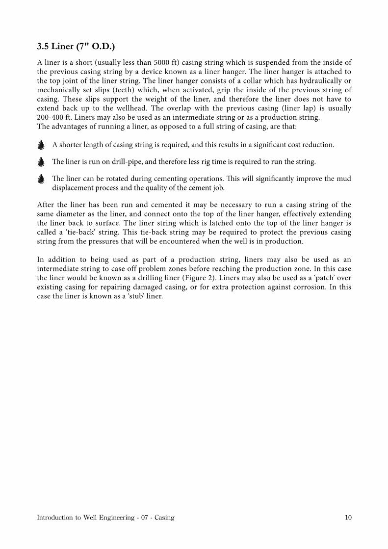
3.5 Liner (7" O.D.)
A liner is a short (usually less than 5000 ft) casing string which is suspended from the inside of the previous casing string by a device known as a liner hanger. The liner hanger is attached to the top joint of the liner string. The liner hanger consists of a collar which has hydraulically or mechanically set slips (teeth) which, when activated, grip the inside of the previous string of casing. These slips support the weight of the liner, and therefore the liner does not have to extend back up to the wellhead. The overlap with the previous casing (liner lap) is usually 200-400 ft. Liners may also be used as an intermediate string or as a production string.The advantages of running a liner, as opposed to a full string of casing, are that:
A shorter length of casing string is required, and this results in a signi#cant cost reduction.
e liner is run on drill-pipe, and therefore less rig time is required to run the string.
e liner can be rotated during cementing operations. is will signi#cantly improve the mud displacement process and the quality of the cement job.
After the liner has been run and cemented it may be necessary to run a casing string of the same diameter as the liner, and connect onto the top of the liner hanger, effectively extending the liner back to surface. The liner string which is latched onto the top of the liner hanger is called a ‘tie-back’ string. This tie-back string may be required to protect the previous casing string from the pressures that will be encountered when the well is in production.
In addition to being used as part of a production string, liners may also be used as an intermediate string to case off problem zones before reaching the production zone. In this case the liner would be known as a drilling liner (Figure 2). Liners may also be used as a ‘patch’ over existing casing for repairing damaged casing, or for extra protection against corrosion. In this case the liner is known as a ‘stub’ liner.
Introduction to Well Engineering - 07 - Casing 10

4. Properties Of Casing
When the casing configuration (casing size and setting depth) has been selected, the loads to which each string will be exposed will be calculated. Casing, of the required size, and with adequate load bearing capacity, will then be selected from manufacturer’s catalogues, or cementing company handbooks.
Casing joints are manufactured in a wide variety of sizes, weights and material grades, and a number of different types of connection are available. The detailed specification of the sizes, weights and grades of casing which are most commonly used has been standardised by the American Petroleum Institute (API). The majority of sizes, weights and grades of casing which are available can be found in manufacturer’s catalogues and cementing company handbooks (e.g. Halliburton Cementing Tables).
Casing is generally classified, in manufacturer’s catalogues and handbooks, in terms of its size (O.D.), weight, grade and connection type:
4.1 Casing Size (Outside Diameter - O.D.)
The size of the casing refers to the Outside Diameter (O.D.) of the main body of the tubular (not the connector). Casing sizes vary from 4.5" to 36" diameter. Tubulars with an O.D. of less than 4.5" are called Tubing. The sizes of casing used for a particular well will generally be limited to the standard sizes that are shown in Figure 3. The hole sizes required to accommodate these casing sizes are also shown in this diagram. The casing string configuration used in any given location e.g. 20" x 13⅜" x 9⅝" x 7" x 4½" is generally the result of local convention, and the availability of particular sizes.
4.2 Length of Joint
The length of a joint of casing has been standardised and classified by the API as follows:
Range Length () Average Length ()
1 16 - 25 222 25 - 34 313 34+ 42
Table 1 - API length ranges
Although casing must meet the classification requirements of the API, set out above, it is not possible to manufacture it to a precise length. Therefore, when the casing is delivered to the rig, the precise length of each joint has to be measured and recorded on a ‘tally sheet’. The length is measured from the top of the connector to a reference point on the pin end of the connection at the far end of the casing joint. Lengths are recorded on the tally sheet to the nearest 100th of a foot. Range 2 is the most common length, although shorter lengths are useful as ‘pup’ joints when attempting to assemble a precise length of string.
Introduction to Well Engineering - 07 - Casing 11

4.3 Casing Weight
For each casing size there are a range of casing weights available. The weight of the casing is in fact the weight per foot of the casing, and is a representation of the wall thickness of the pipe. There may for instance be four different weights of 9⅝" casing:
Weight (lb/) OD (in) ID (in) Wall ickness (in) Dri Diameter (in)
53.5 9.625 8.535 0.545 8.37947 9.625 8.681 0.472 8.525
43.5 9.625 8.755 0.435 8.59940 9.625 8.835 0.395 8.679
Table 2 - 9⅝″ Casing weights
Although there are strict tolerances on the dimensions of casing, set out by the API, the actual I.D. of the casing will vary slightly in the manufacturing process. For this reason the ‘drift’ diameter of casing is quoted in the specifications for all casing. The drift diameter refers to the guaranteed minimum I.D. of the casing. This may be important when deciding whether certain drilling or completion tools will be able to pass through the casing (e.g. the drift diameter of 9⅝″ 53.5 lb/ft casing is less than a 8½″ bit, and therefore an 8½″ bit cannot be used below this casing setting depth. If the 47 lb/ft casing is too weak for the particular application then a higher grade of casing would be used (see below). The nominal I.D. of the casing is used for calculating the volumetric capacity of the casing).
4.4 Casing Grade
The chemical composition of casing varies widely, and a variety of compositions and treatment processes are used during the manufacturing process This means that the physical properties of the steel varies widely. The materials which result from the manufacturing process have been classified by the API into a series of ‘grades’ (Table 3). Each grade is designated by a letter, and a number. The letter refers to the chemical composition of the material, and the number refers to the minimum yield strength of the material (e.g. N-80 casing has a minimum yield strength of 80000 psi, and K-55 has a minimum yield strength of 55000 psi). Hence the grade of the casing provides an indication of the strength of the casing. The higher the grade, the higher the strength of the casing.
In addition to the API grades, certain manufacturers produce their own grades of material. Both seamless and welded tubulars are used as casing, although seamless casing is the most common type of casing, and only H and J grades are welded.
Introduction to Well Engineering - 07 - Casing 12

GradeYield Strength (psi)Yield Strength (psi)
Tensile Strength (psi)Grademin max
Tensile Strength (psi)
H - 40 40000 - 60000J - 55 55000 80000 75000K - 55 55000 80000 95000C - 75 75000 90000 95000L - 80 80000 95000 95000N - 80 80000 110000 100000S - 95* 95000 - 110000P - 110 110000 140000 125000
V - 150* 150000 180000 160000
Table 3 - Casing grades & properties
4.5 Connections
Individual joints of casing are connected together by a threaded connection. These connections are variously classified as: API; premium; gastight; and metal-to-metal seal. In the case of API connections the casing joints are threaded externally at either end, and each joint is connected to the next joint by a coupling which is threaded internally (Figure 4). A coupling is already installed on one end of each joint when the casing is delivered to the rig. The connection must be leak proof but can have a higher or lower physical strength than the main body of the casing joint. A wide variety of threaded connections are available. The standard types of API threaded and coupled connection are:
Short read Connection (STC).
Long read Connection (LTC).
Buttress read Connection (BTC).
Figure 4 - Threaded and coupled connection
Introduction to Well Engineering - 07 - Casing 13

In addition to threaded and coupled connections there are also externally and internally upset connections such as that shown in Figure 5. A standard API upset connection is:
Extreme Line (EL).
Figure 5 - Externally and internally upset casing connection
The STC thread profile is rounded with 8 threads per inch. The LTC is similar but with a longer coupling, which provides better strength and sealing properties than the STC. The buttress thread profile has flat crests, with the front and back cut at different angles. Extreme line connections also have flat crests, and have 5 or 6 threads per inch. The EL connection is the only API connection that has a ‘metal to metal’ seal at the end of the pin, and at the external shoulder of the connection, whereas all of the other API connections rely upon the thread compound, used to make up the connection, to seal off the leak path between the threads of the connection.
In addition to API connections, various manufacturers have developed and patented their own connections (e.g. Hydril, Vallourec, Mannesman). These connections are designed to contain high pressure gas and are often called gastight, premium and metal-to-metal seal connections. These connections are termed metal-to-metal seal because they have a specific surface machined into both the pin and box of the connection, which are brought together and subjected to stress when the connection is made up.
Surveys have shown that over 80% of leaks in casing can be attributed to poor ‘make-up’ of connections. This may be due to a variety of reasons:
Excessive torque used in making-up the connections.
Dirty threads.
Cross-threading.
Using the wrong thread compound.
Introduction to Well Engineering - 07 - Casing 14

The casing string should be tested for pressure integrity before drilling the subsequent hole section. Most of the causes of connection failure can be eliminated by good handling and running procedures on the rig.
The recommended make-up torque for API connections is given in API RP 5C1. These recommended torques are based on an empirical equation obtained from tests using API modified thread compound on API connections. The recommended make up torque for other connections is available from manufacturers.
Introduction to Well Engineering - 07 - Casing 15

5. API Specifications, Standards & Bulletins
The API Committee responsible for the standardisation of tubular goods is Committee number 5. This committee publishes, and continually updates, a series of Specifications, Standards, Bulletins and Recommended Practices covering the manufacture, performance and handling of tubular goods. The documents, published by Committee 5, of particular relevance to casing design and specification are:
API SPEC 5CT, ‘Specification for casing and tubing’: Covers seamless and welded casing and tubing, couplings, pup joints and connectors in all grades. Processes of manufacture, chemical and mechanical property requirements, methods of test and dimensions are included.
API STD 5B, ‘Specification for threading, gauging, and thread inspection for casing, tubing, and line pipe threads’: Covers dimensional requirements on threads and thread gauges, stipulations on gauging practice, gauge specifications and certifications, as well as instruments and methods for the inspection of threads of round-thread casing and tubing, buttress thread casing, and extreme-line casing and drill pipe.
API RP 5A5, ‘Recommended practice for field inspection of new casing, tubing and plain-end drill-pipe’: Provides a uniform method of inspecting tubular goods.
API RP 5B1, ‘Recommended practice for thread inspection on casing, tubing and line pipe’: The purpose of this recommended practice is to provide guidance and instructions on the correct use of thread inspection techniques and equipment.
API RP 5C1, ‘Recommended practice for care and use of casing and tubing’: Covers use, transportation, storage, handling, and reconditioning of casing and tubing.
API RP5 C5, ‘Recommended practice for evaluation procedures for casing and tubing connections’: Describes tests to be performed to determine the galling tendency, sealing performance and structural integrity of tubular connections.
API BULL 5A2, ‘Bulletin on thread compounds’: Provides material requirements and performance tests for two grades of thread compound for use on oil-field tubular goods.
API BULL 5C2, ‘Bulletin on performance properties of casing and tubing’: Covers collapsing pressures, internal yield pressures and joint strengths of casing and tubing, and minimum yield load for drill pipe.
API BULL 5C3, ‘Bulletin on formulas and calculations for casing, tubing, drill-pipe and line pipe properties’: Provides formulas used in the calculations of various pipe properties, also background information regarding their development and use.
API BULL 5C4, ‘Bulletin on round thread casing joint strength with combined internal pressure and bending’: Provides joint strength of round thread casing when subject to combined bending and internal pressure.
Introduction to Well Engineering - 07 - Casing 16

6. Wellheads & Casing Hangers
All casing strings, except for liners, are suspended from a wellhead. On a land well or offshore platform the wellhead is just below the rig floor. When drilling offshore, from a floating vessel, the wellhead is installed at the seabed. These subsea wellheads will be discussed in Chapter 14: relating to Subsea Drilling. The wellhead on a land or platform well is made up of a series of spools, stacked up, one on top of the other (Figure 6). Surface wellhead spools have four functions:
To suspend the weight of the casing string.
To seal off the annulus between successive casing strings at the surface.
To allow access to the annulus between casing strings.
To act as an interface between the casing string and BOP stack.
When the casing string has been run into the well-bore it is hung off, or suspended, by a casing hanger, which rests on a landing shoulder inside the casing spool. Casing hangers must be designed to take the full weight of the casing, and provide a seal between the casing hanger and the spool. There are two types of surface wellhead in common use:
6.1 Spool Type Wellhead
The procedure for installing a spool type wellhead system (Figure 6) can be outlined as follows: 1. e conductor (30") is run and cemented in place. It is then cut off just above the ground level or
the wellhead deck (on a platform).
2. e 26" hole is drilled and the 20" casing is run through the conductor and cemented. Sometimes a landing base is welded onto the top of the 20" casing so that it can rest on the top of the 30” conductor, to transfer some weight to the 30" casing.
3. e 20" casing is cut off just above the 30" casing and a 20" Casing Head Housing (lowermost casing head) is threaded, or welded, onto the top of the 20" casing. e internal pro#le of this housing has a landing surface on which the casing hanger of the subsequent casing string (13⅜") lands. e housing has two side outlets which provide access to the 20"x13⅜" annulus. e upper &ange of the housing is used as the lower part of the connection to the BOP stack used in drilling the next hole section. A ring gasket is used to seal off the connection between the housing and the BOP stack.
4. e 17½" hole is drilled and the 13⅜" casing is run with the hanger landing in the 20" housing. e casing is cemented in place. e BOP stack is disconnected and a casing spool (13⅝") is &anged up on top of the 20" housing. e BOP’s are made up on top of the 13⅝" spool and the 12¼" hole is drilled.
Introduction to Well Engineering - 07 - Casing 17

Figure 6 - API wellhead
Introduction to Well Engineering - 07 - Casing 18

5. The process continues, with a new spool being installed for each casing string. Eventually a tubing head spool is installed. This spool allows the completion tubing to be suspended from the wellhead. The minimum I.D. of a casing spool must be greater than the drift I.D. of the previous casing. A protective sleeve known as a wear bushing is installed in each spool when it is installed, and before the drill-string is run. The wear bushing must be removed before the next casing string is run.
6. Finally the Xmas tree is installed on top of the wellhead (Figure 7). A ring gasket, approved by the API, is used to seal off the space between the flanges on the spools. The gaskets have pressure energized seals, and can be rated up to 15000 psi.
The disadvantages of this type of wellhead are:
A lot of time is spent &anging up the spools.
e large number of seals increases the chance of a pressure leak.
BOP’s must be removed to install the next casing spool.
A lot of headroom is required, which may not be available in the wellhead area of an offshore platform.
Introduction to Well Engineering - 07 - Casing 19

Figure 7 - Conventional Xmas tree
6.2 Compact Spool (Speed-head)
The compact spool was developed as an alternative to the conventional spool discussed above. A compact spool enables several casing strings or tubing to be suspended from a single spool. The first step in using this type of wellhead is to install the 20" casing head housing, as in the case of the spool type wellhead. After the 13⅜" casing is run and cemented, the casing is cut off and the speed-head is connected to the casing head housing. The BOP’s can then be connected to the top of the housing, and the next hole section drilled.The 9⅝" casing is then run, with the hanger resting on a landing shoulder inside the speed-head. A 7" casing string can be run, and landed, in the speed-head in a similar manner to the 9⅝" casing. The tubing string may also be run and landed in the speed-head. The Christmas tree can then be installed on top of the speed-head.
Introduction to Well Engineering - 07 - Casing 20

The disadvantage of the compact spool is that the casing programme cannot be easily altered, and so this system is less flexible than the separate spool system.
6.3 Casing Hangers
There are two types of casing hanger in common use. Wellheads can be designed to accept both types of hanger:
Mandrel (Boll-Weevil) Type Casing Hangers: This type of hanger (Figure 8) is screwed onto the top of the casing string so that it lands in the casing housing when the casing shoe reaches the required depth. Short lengths of casing, known as pup joints may have to be added to the string so that the casing shoe is at the correct depth when the hanger lands in the wellhead. The calculation which determines the length of pup joints required to achieve this positioning is known as spacing out the string. Although this is the most common type of hanger it cannot be used if there is a risk that the casing will not reach bottom and therefore that the hanger will not land in the wellhead.
Slip Type Casing Hangers: This type of hanger (Figure 9) is wrapped around the casing and then lowered until it sits inside the casing spool. The slips are automatically set when the casing is lowered (in a similar fashion to drill-pipe slips) This type of hanger can be used if the casing stands up on a ledge and cannot reach its required setting depth. These types of hanger are also used when tension has to be applied in order to avoid casing buckling when the well is brought into production.
Figure 8 - Mandrel or Boll-Weevil type casing hanger
Introduction to Well Engineering - 07 - Casing 21

Figure 9 - Slip type casing hanger
Introduction to Well Engineering - 07 - Casing 22

7. Rig-Site Operations
Casing leaks are often caused by damaging the threads while handling and running the casing on the rig. It has also been known for a joint of the wrong weight or grade of casing to be run in the wrong place, thus creating a weak spot in the string. Such mistakes are usually very expensive to repair, both in terms of rig time and materials. It is important, therefore, to use the correct procedures when handling or running the casing.
7.1 Handling Procedures
1. When the casing arrives at the rig site the casing should be carefully stacked in the correct running order. is is especially important when the string contains sections of different casing grades and weights. On offshore rigs, where deck space is limited, do not stack the casing too high or else excessive lateral loads will be imposed on the lowermost row. Casing is off-loaded from the supply boat in reverse order, so that it is stacked in the correct running order.
2. e length, grade, weight and connection of each joint should be checked and each joint should be clearly numbered with paint. e length of each joint of casing is recorded on a tally sheet. If any joint is found to have damaged threads it can be crossed off the tally sheet. e tally sheet is used by the drilling engineer to select those joints that must be run so that the casing shoe ends up at the correct depth when the casing hanger is landed in the wellhead.
3. While the casing is on the racks the threads and couplings should be thoroughly checked and cleaned. Any loose couplings should be tightened.
4. Casing should always be handled with thread protectors in place. ese need not be removed until the joint is ready to be stabbed into the string.
7.2 Casing Running Procedures
1. Before the casing is run, a check trip should be made to ensure that there are no tight spots or ledges which may obstruct the casing and prevent it reaching bottom.
2. e dri I.D. of each joint should be checked before it is run (rabbiting).
3. Joints are picked up from the catwalk and temporarily rested on the ramp. A single joint elevator is used to li the joint up through the ‘V’ door into the derrick (Figure 10).
4. A service company (casing crew) is usually hired to provide a ‘stabber’, and one or two &oormen to operate the power tongs. e stabbing board is positioned at the correct height to allow the stabber to centralise the joint directly above the box of the joint suspended in the rotary table. e pin is then carefully stabbed into the box, and the power tongs are used to make up the connection slowly to ensure that the threads of the casing are not cross threaded. Care should be taken to use the correct thread compound to give a good seal. e correct torque is also important and can be monitored from a torque gauge on the power tongs. On buttress casing there is a triangle stamped on the pin end as a reference mark. e coupling should be made up to the base of the triangle to indicate the correct make-up.
Introduction to Well Engineering - 07 - Casing 23

5. As more joints are added to the string the increased weight may require the use of heavy duty slips (spider) and elevators (Figure 11).
6. If the casing is run too quickly into the hole, surge pressures may be generated below the casing in the open hole, increasing the risk of formation fracture. A running speed of 1000 per hour is oen used in open hole sections. If the casing is run with a &oat shoe the casing should be #lled up regularly as it is run, or the casing will become buoyant, and may even collapse under the pressure from the mud in the hole.
7. e casing shoe is usually set some 10-30 off bottom.
Figure 10 - Casing running operations
Introduction to Well Engineering - 07 - Casing 24

Figure 11 - Heavy duty casing elevators
7.3 Casing Landing Procedures
After the casing is run to the required depth it is cemented in place while suspended in the wellhead. The method used for landing the casing will vary from area to area, depending on the forces exerted on the casing string after the well is completed. These forces may be due to changes in formation pressure, temperature, fluid density and earth movements (compaction). These will cause the casing to either shrink or expand, and the landing procedure must take account of this. There are basically 3 different ways in which the casing can be cemented and landed:
Landing the casing and cementing.
Suspending the casing, conducting the cement job and then applying additional tension when the cement has hardened.
Landing the casing under compression.
Introduction to Well Engineering - 07 - Casing 25

The first case does not require any action after the cementing operation is complete. The casing is simply landed on a Boll-Weevil hanger and cemented in place. Additional tension (over and above the suspended weight) may however have to be applied to the casing to prevent buckling due to thermal expansion when the well is producing hot fluids. Additional tension can be applied, after the casing has been cemented, by suspending the casing from the elevators during the cementing operation and then applying an ‘overpull’ (extra tension) to the casing once the cement has hardened. The casing would then be landed on a slip and seal assembly. The level of overpull applied to the casing will depend on the amount of buckling load that is anticipated due to production. The third option may be required in the case that the suspended tension reduces the casing’s collapse resistance below an acceptable level. In this case the casing is suspended from the elevators during cementing and then lowered until the desired compression is achieved before setting the slip and seal assembly.
7.4 Liner Running Procedures
Liners are run on drill-pipe with special tools which allow the liner to be run, set and cemented all in one trip (Figure 12). The liner hanger is installed at the top of the liner. The hanger has wedge slips which can be set against the inside of the previous string. The slips can be set mechanically (rotating the drill-pipe) or hydraulically (differential pressure). A liner packer may be used at the top of the liner to seal off the annulus after the liner has been cemented. The basic liner running procedure is as follows:
1. Run the liner on drill-pipe to the required depth.
2. Set the liner hanger.
3. Circulate drilling &uid to clean out the liner.
4. Back off (disconnect) the liner hanger setting tool.
5. Pump down and displace the cement.
6. Set the liner packer.
7. Pick up the setting tool, reverse circulate to clean out cement and pull out of hole.
Introduction to Well Engineering - 07 - Casing 26

Figure 12 - Casing liner equipment
Introduction to Well Engineering - 07 - Casing 27

8. Casing Design
8.1 Introduction to the Casing Design Process
The casing design process involves three distinct operations: the selection of the casing sizes and setting depths; the definition of the operational scenarios which will result in burst, collapse and axial loads being applied to the casing; and finally the calculation of the magnitude of these loads and selection of an appropriate weight and grade of casing. The steps in the casing design process are shown in Figure 13.
Design Casing String Configuration.
Define Load Cases for Each String.
Calc. Int/Ext & Axial Loads on Each String.
Calc. net Burst & Collapse Loads.
Select Casing Weight & Grade.
Calc. net Axial Loads.
Derate Collapse Rating of Casing based on Axial Loads.
Confirm Casing Selection.
Select Casing Setting Depth. Select Casing Sizes.
Well Objectives,Logging Tools,
Testing Equipment,Production Equipment,
Contingency.
Form. Strength,Popre Pressures,
Mudweights,Geological Considerations,
Directional Wellplan,Drillfluid Selection.
API Ratings of Casing & Design Factors.
Figure 13 - Casing design process
Introduction to Well Engineering - 07 - Casing 28
Pore Pressures

8.1.1 Casing Design: Size and Setting Depths
The casing setting depths are selected on the basis of an assessment of the conditions to be encountered when drilling the subsequent hole section or, in the case of production casing, the completion design.
The first step in deciding upon the setting depth for the surface and intermediate casing strings is to calculate the maximum pressures that could be encountered in the hole section below the string in question. These pressures must not exceed the formation strength at any point in the hole and in particular at the casing shoe. The highest pressure that will be encountered in the open hole section will occur when circulating out a gas influx (see Chapter 6: on Well Control). The formation strength can be estimated from nearby well data or by calculation (see Chapter 5: on Formation Pressures and Fracture Strength). The procedure for establishing the acceptable setting depth (Figure 14) is:
1. Start at Total Depth (TD) of the Well.
2. Determine the formation fracture pressure at all points in the well.
3. Calculate the borehole pressure pro#le when circulating out a gas in&ux from TD.
4. Plot the formation fracture pressure and the well bore pressure when circulating out an in&ux, on the same axes.
5. e casing must be set at least at the depth where the two plots cross i.e. this is the shallowest depth at which the casing can be safely set. If the casing is set any shallower when drilling this hole section then the formation will fracture if an in&ux occurs.
6. Repeat steps 2 to 5 moving up the well, with each subsequent string starting at the casing setting depth for each string.
Figure 14 - Casing setting depth determination
Introduction to Well Engineering - 07 - Casing 29

The setting depth of the casing will also be determined by a range of other considerations such as: the need to isolate weak formations from high mud-weights; isolate lost circulation zones; and to isolate troublesome formations, such as shales, which can cause hole problems whilst drilling subsequent formations.
The casing sizes and string configuration are dictated by the size of the smallest casing string to be run in hole. Once the smallest casing size is known all subsequent casing sizes (and hole sizes) are selected from Figure 3. The smallest casing size is selected on the basis of operational considerations such as: the size and configuration of the completion string or well testing and/or the size of the logging tools to be run through the casing. The drilling engineer will collate this information from the geology, reservoir engineering and production engineering departments. The objective of the drilling engineer is to use the smallest casing sizes possible. It can be readily appreciated that if it is acceptable to use a 4" casing string as the production casing then the next string will be 7", the next 9⅝" and so forth. Hence, if only three casing strings are required then the surface string can be 9⅝". This slimhole design will result in considerable savings in drilling and equipment costs.
8.1.2 Define Operational Scenarios & Consequent Loads on the Casing
The loads to which the casing will be exposed during the life of the well will depend on the operations to be conducted: whilst running the casing; drilling the subsequent hole section; and during the producing life of the well. These operations will result in radial (burst and collapse) and axial (tensile and compressive) loads on the casing strings. Since the operations conducted inside any particular string (e.g. the surface string) will differ from those inside the other strings (e.g. the production string) the load scenarios will be specific to a particular string. The definition of the operational scenarios to be considered is one of the most important steps in the casing design process, they will therefore generally be established as a company policy.
8.1.3 Casing Loads: Weight & Grades
Having defined the size and setting depth for the casing strings, and defined the operational scenarios to be considered, the loads to which the casing will be exposed can be calculated. The particular weight and grade of casing required to withstand these loads can then be determined.
The uniaxial loads to which the casing is exposed are:
Collapse Load
The casing will experience a net collapse loading if the external radial load exceeds the internal radial load (Figure 15). The greatest collapse load on the casing will occur if the casing is evacuated (empty) for any reason. The collapse load, Pc at any point along the casing can be calculated from:
Pc = Pe − Pi
Introduction to Well Engineering - 07 - Casing 30

Figure 15 - Radial loads on casing
Burst Load
The casing will experience a net burst loading if the internal radial load exceeds the external radial load. The burst load, Pb at any point along the casing can be calculated from:
In designing the casing to resist burst loading the pressure rating of the wellhead and BOP stack should be considered since the casing is part of the well control system.
The internal, Pi and external, Pe loads which are used in the determination of the burst and collapse loads on the casing are derived from an analysis of operational scenarios.
External Loads
The following issues are considered when deciding upon the external load (Pe) to which the casing will be subjected:
1. e pore pressure in the formation.If the engineer is satis#ed that it will be possible to displace all of the mud from the annulus between the casing and borehole during the cementing operation, and that a satisfactory cement sheath can be achieved, the formation pore pressure is generally used to determine the load acting on the casing below the top of cement in the annulus, aer the cement has hardened.
Pb = Pi − Pe
Introduction to Well Engineering - 07 - Casing 31

2. e weight of the mud in which the casing was run.If a poor cement bond between the casing and cement, or cement and borehole, is anticipated then the pressure due to a column of mud in the annulus is generally used to determine the load acting on the casing below the top of cement in the annulus, aer the cement has hardened. If the mud has been in place for more than 1 year the weighting material will probably have settled out, and therefore the pressure experienced by the casing will be due to a column of mud mix-water (water or base-oil).
3. e pressure from a column of cement mix-water.e pressure due to the cement mix-water is oen used to determine the external load on the casing during the producing life of the well. is pressure is equal to the density of fresh water or sea water in the case of water-based mud, and base-oil in the case of oil-based mud. e assumption is that the weighting material in the mud (generally Barite) has settled from suspension.
4. e pressure due to a column of cement slurry.e pressure exerted by a column of cement slurry will be experienced by the casing until the cement sets. It is assumed that hardened cement does not exert a hydrostatic pressure on the casing.
5. Blockage in the annulus.If a blockage of the annulus occurs during a stinger cement operation (generally performed on a conductor casing). e excess pumping pressure on the cement will be transmitted to the annulus, but not to the inside of the casing. is will result in an additional external load during stinger cementing. In the case of conventional cementing operations a blockage in the annulus will result in equal and opposite pressures inside and outside the casing.
Internal Loads
It is commonplace to consider the internal loads (Pi) due to the following:
1. Mud to Surface.is will be the predominant internal pressure during drilling operations. e casing design must account for the possibility that the density of the drilling &uid may change during the drilling operation, due to for instance lost circulation, or an in&ux.
2. Pressure due to in#ux.e worst case scenario which can arise, from the point of view of burst loading, is if an in&ux of hydrocarbons occurs, that the well is completely evacuated to gas and simultaneously closed in at the BOP stack.
3. Full Evacuation.e worst case scenario which can arise, from the point of view of collapse loading, is if the casing is completely evacuated.
4. Production Tubing Leak.In the case of production casing speci#cally a leak in the production tubing will result in the tubing pressure being exposed to the casing. e closed in tubing pressure is used as the basis of determining the pressure on the casing. is is calculated on the basis of a column of gas against the formation pressure. e pressure below surface is based on the combined effect of the tubing head pressure, and the hydrostatic pressure due to a column of packer &uid (if there is any in the annulus).
Introduction to Well Engineering - 07 - Casing 32

5. Fracture Pressure of Open Formations.When considering the internal loads on a casing string the fracture pressure in any formations open to the internal pressures must be considered. e pressure in the open hole section cannot exceed the fracture pressure of the weakest formation. Hence, the pressures in the remaining portion of the borehole, and the casing, will be controlled by this fracture pressure. e formation just below the casing shoe is generally considered to be the weakest formation in the open hole section.
Net Radial Loading (Burst or Collapse Load)
When the internal and external loads have been quantified the maximum net radial loading on the casing is determined by quantifying the difference between the internal and external load at all points along the casing. If the net radial loading is outward then the casing is subjected to a burst load. If the net loading is inward then the casing is subjected to a collapse load. The internal and external loads used in the determination of the net load must be operationally compatible, i.e. it must be possible for them to co-exist simultaneously.
Axial Load
The axial load on the casing can be either tensile or compressive, depending on the operating conditions (Figure 16). The axial load on the casing will vary along the length of the casing. The casing is subjected to a wide range of axial loads during installation and subsequent drilling and production. The axial loads which will arise during any particular operation must be calculated and added together to determine the total axial load on the casing.
Figure 16 - Axial loads on casing
Introduction to Well Engineering - 07 - Casing 33

The sources of axial loads on the casing are a function of a number of variables:
W = the dry weight of the casingΦ = the angle of the boreholeAo = the cross sectional area of the outside of the casingAi = the cross sectional area of the inside of the casingDLS = the dogleg severity of the well at any pointPi = the surface pressure applied to the I .D. of the casingAs = the cross sectional area of the pipe bodyΔT = the change in temperature at any point in the well δPi and dδPe = the change in internal and external pressure on the casing v = the poissons ratio for the steel
1. Dry weight of Casing (Fwt).e suspension of a string of casing in a vertical or deviated well will result in an axial load. e total axial load on the casing (the weight of the casing) in air can be calculated from the following:
2. Buoyant Force on Casing (Fbuoy).When submerged in a liquid the casing will be subjected to a compressive axial load. is is generally termed the buoyant force and can be calculated from the following:
3. Bending Stress (Fbend).When designing a casing string in a deviated well the bending stresses must be considered. In sections of the hole where there are severe dog-legs (sharp bends) the bending stresses should be checked. e most critical sections are where dog-leg severity exceeds 10° per 100 . e axial load due to bending can be calculated from the following:
4. Plug Bumping Pressure (Fplug).e casing will experience an axial load when the cement plug bumps during the cementation operation. is axial load can be calculated from the following:
Fwt =W cos Φ
Fbuoy = Pe(Ao − Ai ) Open ended casingFbuoy = Pe Ao − PiAi Closed ended casing
Fbend = 64(DLS)OD(W )
Fplug = Psurf Ai
Introduction to Well Engineering - 07 - Casing 34
δPi and dδPe
Pe(Ao − Ai )Pe Ao
and

5. Overpull when casing stuck (Fpt).If the casing becomes stuck when being run in hole it may be necessary to apply an ‘overpull’ on the casing to get it free. is overpull can be added directly to the axial loads on the casing when it became stuck:
6. Effects of Changes in Temperature (Ftemp).When the well has started to produce the casing will be subjected to an increase in temperature and will therefore expand. Since the casing is restrained at surface in the wellhead and at depth by the hardened cement it will experience a compressive (buckling) load. e axial load generated by an increase in temperature can be calculated by the following:
7. Overpull to Overcome Buckling Forces (Fop).When the well has started to produce the casing will be subjected to compressive (buckling) loads due to the increase in temperature, and therefore expansion of the casing. Attempts are oen made to compensate for these buckling loads by applying an overpull to the casing when the cement in the annulus has hardened. is tensile load (the overpull) is ‘locked into’ the string by using the slip type hanger. e overpull is added directly to the axial load on the casing when the overpull is applied.
8. Axial Force Due to Ballooning (During Pressure Testing) (FBal).If the casing is subjected to a pressure test it will tend to ‘balloon’. Since the casing is restrained at surface in the wellhead, and at depth by the hardened cement, this ballooning will result in an axial load on the casing. is axial load can be calculated from the following:
9. Effect of Shock Loading (FShock).Whenever the casing is accelerated or decelerated, being run in hole, it will experience a shock loading. is acceleration and deceleration occurs when setting or unsetting the casing slips, or at the end of the stroke when the casing is being reciprocated during cementing operations. is shock loading can be calculated from the following:
A velocity of 5cm/sec. is generally recommended for the computation of the shock loading. During installation the total axial load Ft is some combination of the loads described above, and depends on the operational scenarios. The objective is to determine the maximum axial load on the casing when all of the operational scenarios are considered.
Fpt = Direct tension
Ftemp = −200(As )(ΔT )
Fop = Direct overpull
FBal = 2v(AiδPi − AoδPe)
Fshock = 1780 v As
Introduction to Well Engineering - 07 - Casing 35
FBal
Fshock
δPe )

Free Running of Casing:
Running Casing taking account of Shock Loading:
Stuck Casing:
Cementing Casing:
When cemented and additional overpull is applied (‘As Cemented Base Case’):
During Drilling and Production the total axial load Ft is:
Biaxial and Triaxial Loading
It can be demonstrated both theoretically and experimentally that the axial load on a casing can affect the burst and collapse ratings of that casing. This is represented in Figure 17. It can be seen that as the tensile load imposed on a tubular increases, the collapse rating decreases and the burst rating increases. It can also be seen from this diagram that as the compressive loading increases the burst rating decreases and the collapse rating increases. The burst and collapse ratings for casing quoted by the API assume that the casing is experiencing zero axial load. However, since casing strings are very often subjected to a combination of tension and collapse loading simultaneously, the API has established a relationship between these loadings.
Ft + Fwt − Fbuoy + Fbend
Ft = Fwt − Fbuoy + Fbend + Fshock
Ft = Fwt − Fbuoy + Fbend + Fop
Ft = Fwt − Fbuoy + Fplug + Fshock
FtBase = Fwt − Fbuoy + Fbend + Fplug + Fpt
Ft = FtBase + Fbal + Ftemp
Introduction to Well Engineering - 07 - Casing 36

Figure 17 - Tri axial loading on casing
The Ellipse shown in Figure 18 is in fact a 2D representation of a 3D phenomenon. The casing will in reality experience a combination of three loads (Triaxial loading). These are Radial, Axial and Tangential loads (Figure 17). The latter being a result of the other two. Triaxial loading and failure of the casing due to the combination of these loads is very uncommon, and therefore the computation of the triaxial loads on the casing are not frequently conducted. In the case of casing strings being run in extreme environments (>12,000 psi wells, high H2S) triaxial analysis should be conducted.
Design Factors
The uncertainty associated with the conditions used in the calculation of the external, internal, compressive and tensile loads described above is accommodated by increasing the burst collapse and axial loads by a Design Factor. These factors are applied to increase the actual loading figures to obtain the design loadings. Design factors are determined largely through experience, and are influenced by the consequences of a casing failure. The degree of uncertainty must also be considered (e.g. an exploration well may require higher design factors than a development well). The following ranges of factors are commonly used:
Burst design factors 1.0 - 1.33
Collapse design factors 1.0 - 1.125
Tension design factors 1.0 - 2.0
Triaxial design factor 1.25
Introduction to Well Engineering - 07 - Casing 37
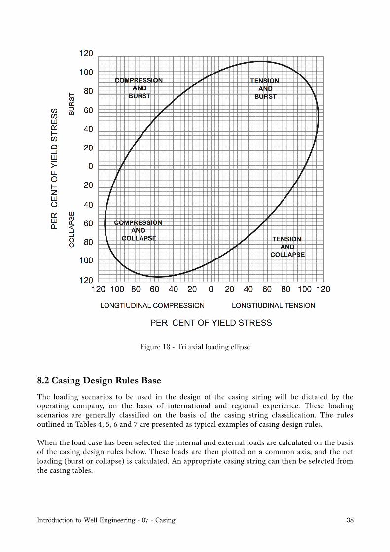
Figure 18 - Tri axial loading ellipse
8.2 Casing Design Rules Base
The loading scenarios to be used in the design of the casing string will be dictated by the operating company, on the basis of international and regional experience. These loading scenarios are generally classified on the basis of the casing string classification. The rules outlined in Tables 4, 5, 6 and 7 are presented as typical examples of casing design rules.
When the load case has been selected the internal and external loads are calculated on the basis of the casing design rules below. These loads are then plotted on a common axis, and the net loading (burst or collapse) is calculated. An appropriate casing string can then be selected from the casing tables.
Introduction to Well Engineering - 07 - Casing 38

Conductor
The predominant concern in terms of failure of the conductor casing during installation is collapse of the casing. Whilst running the casing it is highly unlikely that the casing will be subjected to a differential pressure. When conducting the cement job the inside of the casing will generally contain the drilling fluid in which the casing was run into the well. The maximum external load will be due to the borehole-casing annulus being full of cement (assumes cement to surface). If a stab-in stinger cementation job is conducted, there is the possibility that the annulus will ‘bridge off ’ during the cementing operation, and since this pressure will be isolated from the annulus between the casing and the drill-pipe stinger, this pressure will not be experienced on the inside of the casing. Hence, very high collapse loads will be experienced by the casing below the point at which the bridging occurs.
The design scenario to be used for collapse of conductors in this course is when the casing is fully evacuated, due to lost circulation whilst drilling. In this case the casing is empty on the inside, and the pore pressure is acting on the outside.
The maximum burst load is experienced if the well is closed in after a gas kick has been experienced. The pressure inside the casing is due to formation pore pressure at the bottom of the well, and a column of gas which extends from the bottom of the well to surface. It is assumed that pore pressure is acting on the outside of the casing.
Note that it would be very unusual to close a well in due to a ‘shallow’ kick below the conductor. It would be more common to allow the influx to flow to surface, and divert it away from the rig. This is to avoid the possibility of the formation below the shoe fracturing.
Operation Scenario Load Condition Internal Load External Load
Installation1 Running casing Mud to surface Mud to surface
InstallationBurst 2 Conventional
cement jobMud to surface Cement column to surface
Collapse 3 Stinger cement job Mud to surface Cement column to surface
Collapse Load 4
Stab-in cement job
Mud to surface Cement column to surface plus bridging pressure in the annulus
Drilling -Burst Load
5 Burst Loads - Development well
Pressure due to full column of gas on pore pressure at DSOH depth
Pore pressureDrilling -Burst Load
6 Burst Loads - Exploration well
Pressure due to full column of gas on pore pressure at DSOH
Pore pressure
Drilling - Collapse
7 Collapse Load - Development well Full evacuation of casing Pore pressure
Collapse Load 8 Collapse Load -
Exploration well Full evacuation of casing Pore pressure
Table 4 - Casing design rules for conductors
Introduction to Well Engineering - 07 - Casing 39

Surface Casing
Once the surface casing has been set a BOP stack will be placed on the wellhead, and in the event of a kick the well will be closed in at surface, and the kick circulated out of the well. The surface casing must therefore be able to withstand the burst loads which will result from this operation. Some operators will require that the casing be designed to withstand the burst pressures which would result from internal pressures due to full evacuation of the well to gas.
The maximum collapse loads may be experienced during the cement operation, or due to lost circulation whilst drilling ahead.
The design scenario to be used for collapse of surface casing in this course is when the casing is fully evacuated, due to lost circulation whilst drilling. In this case the casing is empty on the inside and the pore pressure is acting on the outside.
The maximum burst load is experienced if the well is closed in after a gas kick has been experienced. The pressure inside the casing is due to formation pore pressure at the bottom of the well, and a column of gas which extends from the bottom of the well to surface. It is assumed that pore pressure is acting on the outside of the casing.
Operation Scenario Load Condition Internal Load External Load
1 Running casing Mud to surface Mud to surface
Installation2 Conventional
cement jobMud to surface Cement column to surface
Installation3 Stinger cement job Mud to surface Cement column to surface
4Stab-in cement job
Mud to surface Cement column to surface plus bridging pressure in the annulus
Drilling -Burst Load
5 Burst Loads - Development well
Pressure due to full column of gas on pore pressure at DSOH depth
Pore pressureDrilling -Burst Load
6 Burst Loads - Exploration well
Pressure due to full column of gas on pore pressure at DSOH depth
Pore pressure
Drilling - Collapse
7 Collapse Load - Development well Full evacuation of casing Pore pressure
Collapse Load 8 Collapse Load -
Exploration well Full evacuation of casing Pore pressure
Table 5 - Casing design rules for surface casing
Introduction to Well Engineering - 07 - Casing 40

Intermediate Casing
The intermediate casing is subjected to similar loads to the surface casing.
The design scenario to be used for collapse of intermediate casing in this course is when the casing is fully evacuated, due to lost circulation whilst drilling. In this case the casing is empty on the inside and the pore pressure is acting on the outside.
The maximum burst load is experienced if the well is closed in after a gas kick has been experienced. The pressure inside the casing is due to formation pore pressure at the bottom of the well and a column of gas which extends from the bottom of the well to surface. It is assumed that pore pressure is acting on the outside of the casing.
Operation Scenario Load Condition Internal Load External Load
Installation1 Running casing Mud to surface Mud to surface
Installation
2 Conventional cement job
Mud to surface Cement column to TOC & mud/spacer above TOC
Drilling -Burst Load
3 Burst Loads - Development well
Pressure due to full column of gas on pore pressure at DSOH depth
Pore pressureDrilling -Burst Load
4 Burst Loads - Exploration well
Pressure due to full column of gas on pore pressure at DSOH depth
Pore pressure
Drilling - Collapse
5 Collapse Load - Development well Full evacuation of casing Pore pressure
Collapse Load 6 Collapse Load -
Exploration well Full evacuation of casing Pore pressure
Table 6 - Casing design rules for intermediate casing
Production Casing
The design scenarios for burst and collapse or the production casing are based on production operations.
The design scenario to be used for burst of production casing in this course is when a leak is experienced in the tubing just below the tubing hanger. In this event the pressure at the top of the casing will be the result of the reservoir pressure, minus the pressure due to a column of gas. This pressure will the act on the fluid in the annulus of well, and exert a very high internal pressure at the bottom of the casing.
The design scenario to be used for collapse of production casing in this course is when the annulus between the tubing and casing has been evacuated, due to the use of gaslift.
Introduction to Well Engineering - 07 - Casing 41

Operation Scenario Load ConditionLoad Condition Internal Load External Load
Installation1 Running casing Mud to surface Mud to surface
Installation
2 Conventional cement job
Mud to surface Cement column to TOC & mud/spacer above TOC
Production -Burst Load 3
Burst Loads - Explorations & Development well
At surface: Pressure due to column of gas on formation pressure at producing formation and;
At top of packer: Pressure due to column of gas on formation pressure at producing formation action on top of the packer fluid
Pore pressure
Production -Collapse Load
4Collapse Load - Exploration & development well
Full evacuation of casing down to packer Pore pressure
Table 7 - Casing design rules for production casing
8.3 Other Design Considerations
In the previous sections the general approach to casing design has been explained. However, there are special circumstances which cannot be satisfied by this general procedure. When dealing with these cases a careful evaluation must be made and the design procedure modified accordingly. These special circumstances include:
Temperature effects - high temperatures will tend to expand the pipe, causing buckling. is must be considered in geothermal wells.
Casing through salt zones - massive salt formations can &ow under temperature and pressure. is will exert extra collapse pressure on the casing, and cause it to ‘shear’. A collapse load of around 1 psi/ (overburden stress) should be used for design purposes where such a formation is present.
Casing through H2S zones - if Hydrogen Sulphide is present in the formation it may cause casing failures due to hydrogen embrittlement. Special grade casing is specially manufactured for use in H2S zones.
Introduction to Well Engineering - 07 - Casing 42

8.4 Summary of Design Process
The design process can be summarised as follows:
1. Select the casing sizes and setting depths on the basis of: the geological and pore pressure prognosis provided; and the production tubing requirements on the basis of the anticipated productivity of the formations to be penetrated.
2. De#ne the operational scenarios to be considered during the design of each of the casing strings. is should include installation, drilling and production (as appropriate) operations.
3. Calculate the burst loading on the particular casing under consideration.
4. Calculate the collapse loading on the particular casing under consideration.
5. Increase the calculated burst and collapse loads by the Design Factor which is appropriate to the casing type and load conditions considered.
6. Select the weight and grade of casing (from manufacturers tables or service company tables) which meets the load conditions calculated above.
7. For the casing chosen, calculate the axial loading on the casing. Apply the design factor for the casing and load conditions considered, and check that the pipe body yield strength of the selected casing exceeds the axial design loading. Choose a coupling whose joint strength is greater than the design loading. Select the same type of coupling throughout the entire string.
8. Taking the actual tensile loading from above determine the reduction in collapse resistance at the top and bottom of the casing.
Several attempts may have to be made before all these loading criteria are satisfied and a final design is produced. When deciding on a final design bear the following points in mind:
Include only those types of casing which you know are available. In practice only a few weights and grades will be kept in stock.
Check that the #nal design meets all requirements, and state clearly all design assumptions.
If several different designs are possible, choose the most economical scheme that meets requirements.
Introduction to Well Engineering - 07 - Casing 43

Appendix
API Rated Capacity of Casing
The API use the following equations to determine the rated capacity of casing:
(a) Collapse Rating
Yield strength collapse (theoretical)
Plastic collapse (empirical)
Transition collapse (theoretical)
Plastic collapse (theoretical)
where;
A = 2.8762 + 0.10679 x 10⁵YP + 0.21301 x 10⁻¹⁰YP2 − 0.53132 x10⁻¹⁶YP3
B = 0.026233+ 0.50609 x10⁻⁶YP
C = −465.93+ 0.030867YP − 0.10483x10⁻⁷YP2 − 0.36989 x10⁻¹³YP3
Introduction to Well Engineering - 07 - Casing 44
Py = 2YP
Dt
⎛⎝⎜
⎞⎠⎟ −1
Dt
⎛⎝⎜
⎞⎠⎟2
⎡
⎣
⎢⎢⎢⎢
⎤
⎦
⎥⎥⎥⎥
PP = YPADt
⎛⎝⎜
⎞⎠⎟− B
⎡
⎣
⎢⎢⎢⎢
⎤
⎦
⎥⎥⎥⎥
−C
Pt= YP F
Dt
⎛⎝⎜
⎞⎠⎟−G
⎡
⎣
⎢⎢⎢⎢
⎤
⎦
⎥⎥⎥⎥
Pc =
2E1−2
Dt
Dt−1⎛
⎝⎜⎞⎠⎟2⎡
⎣⎢
⎤
⎦⎥
x
x
x
x x
x
Pt

G = FB / AYP = Yield strength
(b) Internal yield pressure
Pipe body
(c) Tensile Rating
(d) Triaxial Loading
The triaxial load is expressed in terms of the Von Mises Equivalent Stress. This is compared with the minimum yield strength of the casing.
F =46.95 x10⁶ 3B / A
2 + B / A⎛⎝⎜
⎞⎠⎟3⎡
⎣⎢
⎤
⎦⎥
YP 3B / A2 + B / A
⎛⎝⎜
⎞⎠⎟ 1− 3B / A
2 + B / A⎛⎝⎜
⎞⎠⎟2⎡
⎣⎢
⎤
⎦⎥
TR = Ys As
Introduction to Well Engineering - 07 - Casing 45
P = 0.875 2YPtD