case study: renovation of a fully-deteriorated trunk sewer at … · 2014-06-06 · •...
TRANSCRIPT

TRENCHLESS TECHNOLOGY ROADSHOW May 28-29, 2014 – Scotiabank Convention Centre, Niagara Falls, ON
CASE STUDY: Renovation of a Fully-deteriorated Trunk Sewer
at a Large U.S. BreweryEvanco Environmental Technologies Inc.
Kyle Verwey and Randy Cooper

AGENDA• Project Overview
• Condition Assessment and Risks
• Bypass Design Development and Challenges
• Cured-In-Place Pipe Lining
• Manhole Rehabilitation
• Challenges and Lessons Learned
• Conclusions and Summary

Project Overview
• Primary process waste trunk sewer for a large U.S. Brewery was found to be fully deteriorated
• Approximately 1 mile of 36-inch diameter pipe comprised of Vitrified Clay, Ductile Iron, and Reinforced Concrete
• 21 deteriorated concrete manholes, including 3 large vaults, and 2 drop structures
• Process sewer flows directly beside a fresh water canal, which supplies over 300,000 local people with drinking water
• Numerous segments of pipe found unstable with limited access

System Overview
MH 2A*MH 3
MH 3AMH 4
MH 4A
MH 8
MH 6A‐6
MH 7
MH 9
MH 10
MH 12
MH 11
MH 14MH 13
MH 16MH 15
MH 17MH 19
N
*Manhole to be installed
MH 18MH 20 MH 21
Fresh Water Canal
APTP
PWTP

Condition Assessment
• Sewer was initially identified as significantly deteriorated in 2011 when a backhoe driving over the pipeline collapsed the pipeline at the most downstream end of the sewer
• This collapse initiated an inspection of the entire length of the sewer
• Significant corrosion was identified beginning from the Anaerobic Pre-Treatment Plant (APTP) and continuing downstream

Condition Assessment - Pipelines• Significant pipe obvert corrosion (above
flowline)
• Colonization of pipe crowns by Thiobacillus bacteria caused by high concentrations of H2S gas

• Corrosion Failure Mechanism
• APTP generates high concentration of hydrogen sulfide (H2S) in downstream sewer pipes and manholes.
• Airborne Thiobacillus bacteria attaches to pipe crowns and multiplies.
• Bacteria oxidizes H2S (consumes sulfur), producing sulfuric acid (H2SO4) above flow line
• Sulfuric acid corrodes both concrete (RCP) and ductile iron (DI) pipe crowns weakening and eventually collapsing pipes at crowns.

Risk of Pipeline Instability Very High
• Large sections of pipe obverts were missing
• Soil arching only mechanism keeping the pipe intact

Condition Assessment – Unmapped Pipeline Obstruction Added Risk
• Concrete sanitary sewer (neighbouring City Trunk!) found crossing process sewer at right angles (red arrow).
• Concrete pipe corroded and obstructing 50% of sectional process flow area.
• Design change needed to stabilize pipe and accommodate structural rehabilitation with CIPP.

Condition Assessment - Manholes• Heavy corrosion noticed from the surface (frames and covers)
– heavy H2S odours
• Some covers had been locally repaired to maintain stability (red arrow)

Condition Assessment - Manholes• Heavy corrosion of concrete shafts and
surface slabs
• Manhole 3A (below) concrete top slab had corroded from 9” to less than 4”

Other Assessed Risks• Process sewer buried beneath a large embankment for 2500’,
directly beside a fresh water canal
• This embankment also has: High Pressure Natural Gas lines, 24” Sanitary Sewer, Sludge Force Mains, Manholes and Poison Ivy

Bypass Design Development - Challenges• Single bypass designed for full
project duration (one header, with back-up pumps)
• No available access point - a new pump manhole was to be created
• Depth of the sewer and the elevation of site (mountains) forced pumps to be set below grade
• Access point had buried obstructions including a 18” process force main and a 10” water main with only 9’ between
18” Process Force Main
10” Water Main
Trench Box with 8’ Spreaders
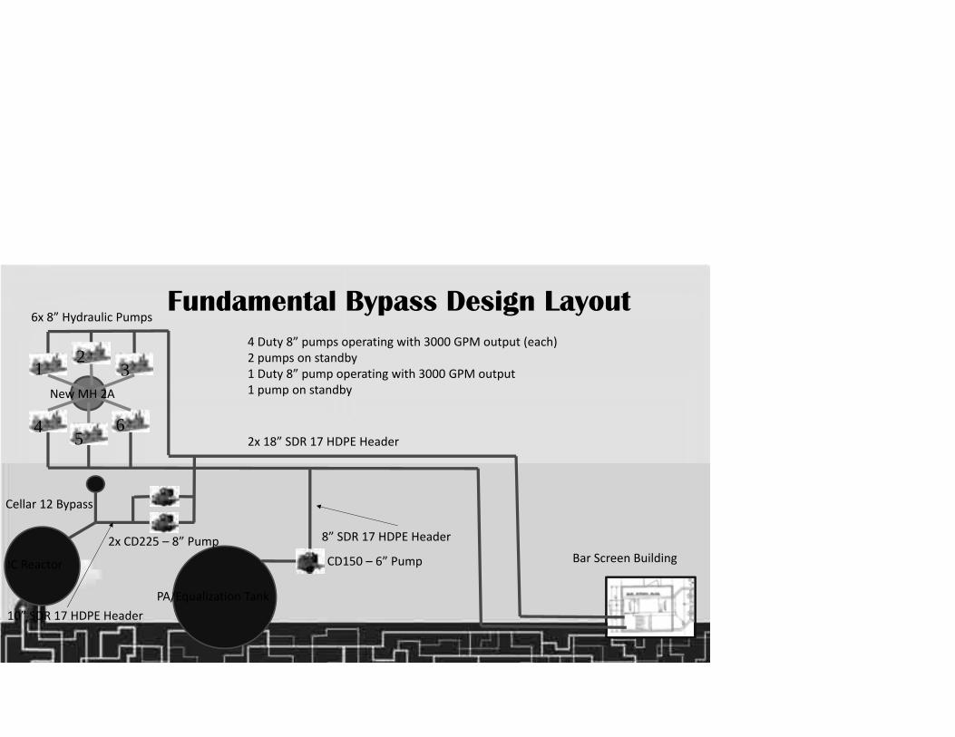
Fundamental Bypass Design Layout
12
3
45
6
Bar Screen Building
PA/Equalization Tank
IC Reactor
Cellar 12 Bypass
CD150 – 6” Pump2x CD225 – 8” Pump
6x 8” Hydraulic Pumps
2x 18” SDR 17 HDPE Header
10” SDR 17 HDPE Header
8” SDR 17 HDPE Header
4 Duty 8” pumps operating with 3000 GPM output (each)2 pumps on standby1 Duty 8” pump operating with 3000 GPM output1 pump on standbyNew MH 2A
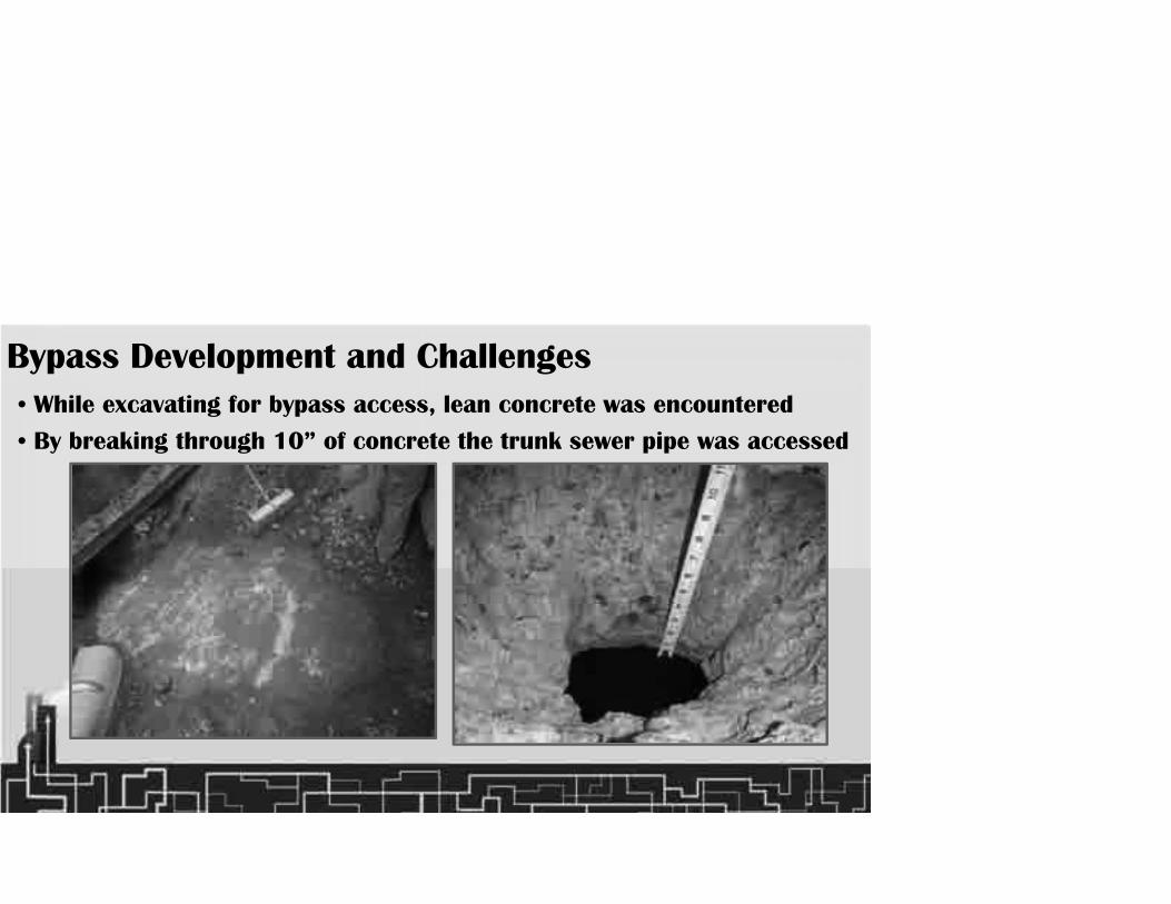
Bypass Development and Challenges• While excavating for bypass access, lean concrete was encountered
• By breaking through 10” of concrete the trunk sewer pipe was accessed

Bypass Development and Challenges• The 36” process sewer was completely encased in concrete with no
mention on any plant drawing
• 3 weeks of 24-hr operations to expose the pipe (red arrow)

Bypass Development and Challenges• Schedule change pushed Evanco into winter lining operations, at high
elevations, in the foothills of a mountain range

Bypass Development and Challenges• After excavating concrete and soil, a sump was constructed adjacent to the 36”
process sewer to support the pump around bypass
• The process pipe was side-cut (live) to create suction sump in very tight quarters

Bypass Development and Challenges• Hydraulic submersible pumps were used to protect man entry as well
as manage very tight space limitations
• Flow was stopped using pneumatic sewer plugs, and 24/7 bypass was established

• During bypass development and concrete cutting work, heavy, cold rain events added more delays
• Heavy rains precipitated downstream pipe failure close to the site of previous 2011 collapse
Pipeline Bypass Challenges – Pipeline Collapse
2011 Patch Repair Concrete
New 36” OD RCP Pipe has a wall thickness of 3.5”

• Evanco quickly repaired the collapse with HDPE, and backfilled with concrete surround to facilitate lining.
Pipeline Bypass Challenges – Pipeline Repair

CURED-IN-PLACE PIPE LINING – Winter Weather• Once bypass was established;
cleaning, inspecting, and lining began
• Embankment roadway could not support heavy lining equipment
• Crane mats were installed to support lining equipment loads
Fresh Water Canal
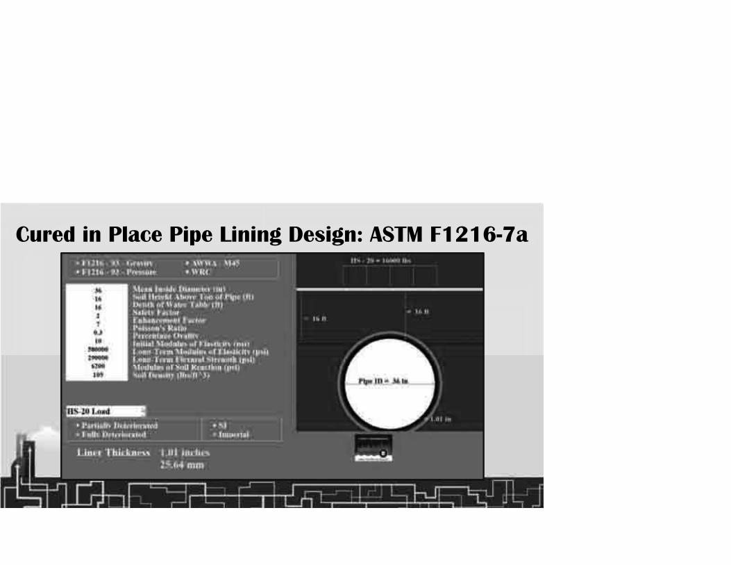
Cured in Place Pipe Lining Design: ASTM F1216-7a

CURED-IN-PLACE PIPE LINING• Seven structural liners were used to span the entire mile of sewer
• Two additional manholes were installed around the sanitary sewer obstruction – at these locations the process sewer was also encased in concrete and had to be cored.
48” Concrete Core
Bypass Piping
Sanitary Manhole
New Manhole #1
New Manhole #2

Weather Challenges – Bypass Pump Failures
• Winter arrived with record low temperatures during lining operations
• During a night of -30°C temperatures six out of eight bypass pumps failed, for different reasons (dead battery, frozen impellor, clumping fuel, hydraulic leak, oil leak, and broken starter)
• Fortunately, no lining operations were underway and brewery was returned to gravity flow – no interruption to brewery operations
• Bypass was restored and additional safety measures were applied to address the cold weather
• Lining operations continued with only 1 day lost

MANHOLE REHABILITATION• State of corrosive decay was alarming
• All manholes needed cleaning, patching, and, in some cases, sectional replacement
New Installed Ring

MANHOLE REHABILITATION• Primary vault structure from Anaerobic Pre-Treatment was reduced to
a shell from original 9-inch wall thickness

MANHOLE REHABILITATION• Evanco used a combination of pressure wash, re-pointing with epoxy concrete, and
structural design/application of high-build, rigid PU to restore structural integrity
• New pre-cast tops/frames/covers with epoxy undercoats were fitted on renovated shafts

LESSONS LEARNED• Importance of accuracy in condition assessment and stability
assessment for fully-deteriorated sewers
• Importance of comprehensive design and planning for all elements (including cold weather, high elevations, collateral assets - canal)
• Importance of having an experienced team of engineers, operations and management personnel
• Importance of flexibility and innovation in responding to buried unknowns
• Importance of back-up plans to ensure no plant shutdowns
• Risk assessment can make or break a project

CONCLUSION AND SUMMARY• After numerous challenges, the project was completed without any
operational impacts on brewery operations or fresh water canal operations
• Teamwork, planning and experience were essential elements of success

THANK YOU!QUESTIONS?