case study on a deep excavation in baku: flame towers ... pg afatoglu.pdfcase study on a deep...
TRANSCRIPT
Case study on a deep excavation in Baku: Flame Towers project earth retaining system
H. A. Afatoglu1 ENAR Engineers Architects & Consultants, Istanbul, Turkey
ABSTRACT
Baku Flame Towers Project, consisting of three high-rise towers, a shopping mall and an underground car park is being constructed in Baku, Azerbaijan. The project site is located on the city center neighboring two major boulevards, and someimportant buildings such as National Assembly of Azerbaijan, General Staff Building and Central Clinic Hospital. The soil profile at the site generally consists of a fill layer and slope debris with varying thicknesses from the ground surface, and verystiff – hard clayey silt underlying the fill layer. Below the silt layer, a poorly cemented sedimentary rock layer with a poor rock quality is encountered. Due to the inclined topography of the project site, excavation slopes with depths varying between 2.0mand 29.0m have been foreseen in accordance with the architectural design. In order to carry out the foundation excavation safely an earth retaining structure consisting of bored piles tied-back by temporary ground anchors has been designed and constructed successfully. The retaining system constructed within Baku Flame Towers Project has the distinction to support the deepest foundation excavation ever made in Baku, Azerbaijan. Due to high structural loads, tower buildings have been designed to reston raft foundations with large diameter piles. Bored piles with a diameter of D=1.20m and length of L=36.0m have been designed in accordance with the required load capacities, and anticipated pile capacities have been proved successfully with pileloading tests performed by using Osterberg Cells. Keywords: deep excavation, retaining system, ground anchors, bored piles, piled raft
1 Enargeo Engineers, Architects and Consultants, Nispetiye cad. Toren sok. Tura apt. no. 1/11 levent, Istanbul, Turkey. [email protected]
1 INTRODUCTION
Flame Towers Project is one of the most prestigious projects in Baku, Azerbaijan (Figure 1). The project stands out among Baku’s ongoing investments in terms of its location, architectural concept and investment value. Besides, it is distinct from other projects in the sense of geotechnical engineering, since many different geotechnical engineering subjects have been studied during the foundation excavation of the towers.
The project site is located in the heart of the city, surrounded by some important buildings and two major boulevards. Due to the neighboring structures and the depth of the foreseen foundation excavation, the necessity for the construction of a retaining system has risen.
Therefore, an earth retaining system composed of bored piles laterally supported by temporary ground anchors has been constructed at the project site. Besides, due to high structural loads that were predicted to be exerted from the superstructures, foundations of the Towers were designed to be constructed on raft foundations with bored piles of large diameters.

Figure 1. Flame Towers
2 SUBSURFACE INVESTIGATION
In order to evaluate the foundation types of the proposed buildings and to design the earth retaining system, soil investigation works were conducted by Enar Eng. Arch. and Consultants (ENAR) in 2007. Nine soil borings with a total length of 380m were drilled within the soil investigation works. Standard laboratory tests were performed on disturbed and undisturbed samples taken from the borings. Besides, four seismic refraction tests, up to a depth of 12-15m were performed by ENAR in order to confirm the stratification of the subsurface layers and determine the thickness of the fill layer that was encountered during the soil borings.
Additional soil investigation works, containing soil borings (a number of 25 with a total length of 1390m) and geophysical investigations (up to 100m depth) were performed on the site by Ministry of Emergency Situations (MES) in July, 2008.
2.1 Soil Profile
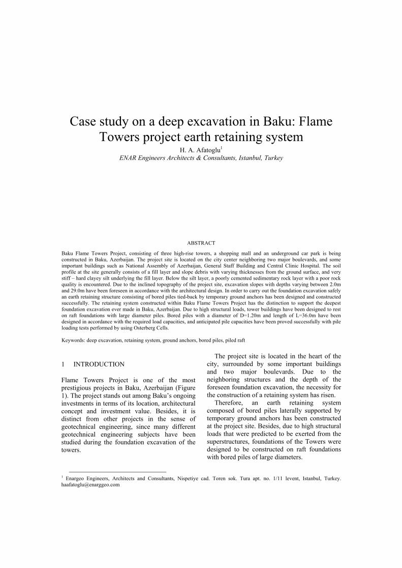
According to the subsurface investigations, the soil profile of the investigation site consists of four main soil layers. There is a 3.50 m to 9.00 m thick artificial fill layer and slope debris on the ground surface. These layers are heterogeneous and they contain from fine to coarse-grained materials. A 20.0m thick very stiff clayey silt layer with occasional sand belts is encountered during soil borings below the fill layer.
This layer generally consists of 2-3% gravel, 20 to 40% sand, 60 to 80% silt+clay. Percentage of clay-sized grains is around 20%. The liquid limit and plastic limit values are approximately wL = 30% and wp = 15%, respectively. Plasticity index is about Ip = 12 to 15%. This layer is classified as low plasticity clay (CL) or low plasticity silt (CL-ML) based on the Unified Soil Classification System (USCS) [4].
Below the brown, very stiff clayey silt, there is a dark gray or dark brown colored, hard clayey silt layer containing sea shells. The thickness of this layer varies between 3.0m to 10.0m along the investigation site. This unit contains 5 to 9% gravel in patches. The sand percentage changes between 15% to 50%, silt+clay is around 50 to 85%. Clay percentage is generally around 20-25%. The consistency limits of this layer are wL = 30%, wP = 15%, Ip = 15% and this soil layer is classified as CL or CL-ML in accordance with USCS.
There is a 10.0m-15.0m thick layer of white colored, poorly cemented seashells featuring limestone with very weak rock properties encountered at 25.0m to 30.0m depth from the ground surface. A sandy clayey silt layer is encountered again below this weak cemented zone, and all soil borings are terminated within this layer.
In accordance with the data gained from in-situ and laboratory tests performed during the subsurface investigations, soil parameters given in Table 1 are used in the design of the retaining system. The soil model is given in Figure 2.
Table 1. Soil parameters used in the design of earth retaining system
Soil Layer Fill-Slope Debris
Very stiff Silt Hard Silt Weak
Rock Unit Weight, γn 18kN/m3 20kN/m3 20kN/m3 22kN/m3 SPT N60 20 - >50 20 -25 30 -35 >50 Cohesion, c 5 kPa 20 kPa 35 kPa 5 kPa Internal Friction Angel, φ 28° 30° 32° 40°
Modulus of Elasticity, Eref (Unload-Reload Condition)
15MPa 45MPa 60MPa 150MPa
Poisson’s Ratio, ν 0.33 0.33 0.33 0.25
3 EARTH RETAINING SYSTEM
The design of the retaining wall and the methodology of the foundation excavation have been executed in accordance with the soil profile encountered at the construction site. The retaining system had to fulfill the following requirements: - to be a rigid system so as to minimize the
effects on the neighboring structures - to keep displacements in a limited range - to be economical and applicable - to provide safety against global stability of
the construction site
Figure 2. Soil model
In this sense, a retaining system composed of
bored piles with various diameters (D = 80cm and D = 100cm) and various depths (L = 7.5m to L = 33.0m), and temporary ground anchors as lateral supports was designed for the foundation excavations of Towers by using Plaxis 8.6 Finite Element Program. Depth of the foundation
excavation varies between 1.0m to 29.0m due to the inclined topography of the project site.
3.1 Design of the Retaining System
The retaining system has been designed as a rigid system so as to accommodate the deformations that may emerge in clayey – sandy silt layers due to stress relief during foundation excavations. Therefore, the retaining system has been laterally supported with multi-level temporary ground anchors with horizontal and vertical spacing selected based on the allowable anchor capacity limitation. Maximum pre stress load that would be applied to ground anchors installed in clayey sandy silt layer has been selected in accordance with “FHWA-IF-99-015 Ground Anchors and Anchored Systems”[5].
According to “FHWA-IF-99-015 Ground Anchors and Anchored Systems”, the value of ultimate skin friction between cement and slightly sandy silts may be taken as 250kPa. Under these circumstances, with a bond length (Lbond) of 8.0m and a drill diameter (D) of 0.125m, maximum allowable anchorage load can be calculated:
Tmax = 8.0m*(0.125*3,14*250)/(2) = 390kN ≈ 40tons (Fs = 2.0)
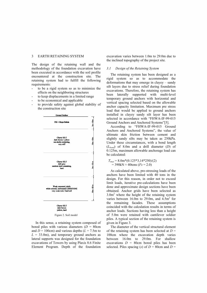
As calculated above, pre-stressing loads of the anchors have been limited with 40 tons in the design. For this reason, in order not to exceed limit loads, iterative pre-calculations have been done and approximate design sections have been obtained. Anchor grids have been selected as 3.0m2 where the height of the retaining system varies between 16.0m to 29.0m, and 4.5m2 for the remaining facades. These assumptions coincided with the calculation results in terms of anchor loads. Sections having less than a height of 5.0m were retained with cantilever soldier piles. A typical section of the retaining system is given in Figure 3.
The diameter of the vertical structural element of the retaining system has been selected at D = 100cm where the excavation depth varies between 16.0m to 29.0m. For shallow excavations D = 80cm bored piles has been selected. Piles spacing (s) of D = 80cm and D =
100cm were selected as s = 94cm and s = 120cm so as to prevent spillage of silt layers between piles, respectively.
Figure 3. A typical section of the retaining system
3.2 Monitoring of the Retaining System
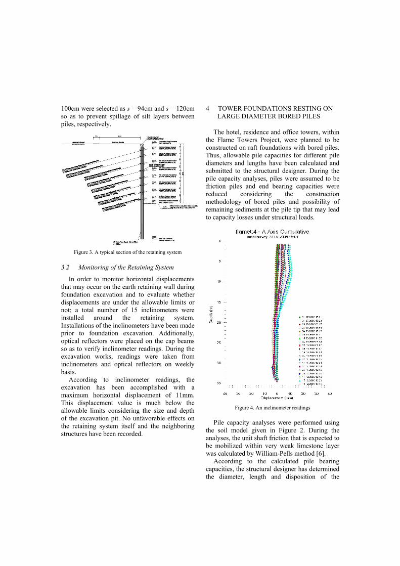
In order to monitor horizontal displacements that may occur on the earth retaining wall during foundation excavation and to evaluate whether displacements are under the allowable limits or not; a total number of 15 inclinometers were installed around the retaining system. Installations of the inclinometers have been made prior to foundation excavation. Additionally, optical reflectors were placed on the cap beams so as to verify inclinometer readings. During the excavation works, readings were taken from inclinometers and optical reflectors on weekly basis.
According to inclinometer readings, the excavation has been accomplished with a maximum horizontal displacement of 11mm. This displacement value is much below the allowable limits considering the size and depth of the excavation pit. No unfavorable effects on the retaining system itself and the neighboring structures have been recorded.
4 TOWER FOUNDATIONS RESTING ON LARGE DIAMETER BORED PILES
The hotel, residence and office towers, within the Flame Towers Project, were planned to be constructed on raft foundations with bored piles. Thus, allowable pile capacities for different pile diameters and lengths have been calculated and submitted to the structural designer. During the pile capacity analyses, piles were assumed to be friction piles and end bearing capacities were reduced considering the construction methodology of bored piles and possibility of remaining sediments at the pile tip that may lead to capacity losses under structural loads.
Figure 4. An inclinometer readings
Pile capacity analyses were performed using
the soil model given in Figure 2. During the analyses, the unit shaft friction that is expected to be mobilized within very weak limestone layer was calculated by William-Pells method [6].
According to the calculated pile bearing capacities, the structural designer has determined the diameter, length and disposition of the
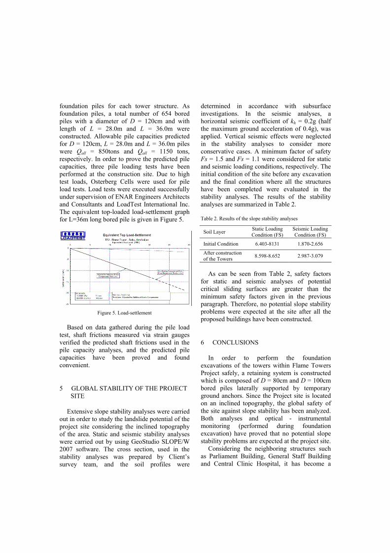
foundation piles for each tower structure. As foundation piles, a total number of 654 bored piles with a diameter of D = 120cm and with length of L = 28.0m and L = 36.0m were constructed. Allowable pile capacities predicted for D = 120cm, L = 28.0m and L = 36.0m piles were Qall = 850tons and Qall = 1150 tons, respectively. In order to prove the predicted pile capacities, three pile loading tests have been performed at the construction site. Due to high test loads, Osterberg Cells were used for pile load tests. Load tests were executed successfully under supervision of ENAR Engineers Architects and Consultants and LoadTest International Inc. The equivalent top-loaded load-settlement graph for L=36m long bored pile is given in Figure 5.
Figure 5. Load-settlement
Based on data gathered during the pile load
test, shaft frictions measured via strain gauges verified the predicted shaft frictions used in the pile capacity analyses, and the predicted pile capacities have been proved and found convenient.
5 GLOBAL STABILITY OF THE PROJECT SITE
Extensive slope stability analyses were carried out in order to study the landslide potential of the project site considering the inclined topography of the area. Static and seismic stability analyses were carried out by using GeoStudio SLOPE/W 2007 software. The cross section, used in the stability analyses was prepared by Client’s survey team, and the soil profiles were
determined in accordance with subsurface investigations. In the seismic analyses, a horizontal seismic coefficient of kh = 0.2g (half the maximum ground acceleration of 0.4g), was applied. Vertical seismic effects were neglected in the stability analyses to consider more conservative cases. A minimum factor of safety Fs = 1.5 and Fs = 1.1 were considered for static and seismic loading conditions, respectively. The initial condition of the site before any excavation and the final condition where all the structures have been completed were evaluated in the stability analyses. The results of the stability analyses are summarized in Table 2.
Table 2. Results of the slope stability analyses
Soil Layer Static Loading Condition (FS)
Seismic Loading Condition (FS)
Initial Condition 6.403-8131 1.870-2.656
After construction of the Towers 8.598-8.652 2.987-3.079
As can be seen from Table 2, safety factors
for static and seismic analyses of potential critical sliding surfaces are greater than the minimum safety factors given in the previous paragraph. Therefore, no potential slope stability problems were expected at the site after all the proposed buildings have been constructed.
6 CONCLUSIONS
In order to perform the foundation excavations of the towers within Flame Towers Project safely, a retaining system is constructed which is composed of D = 80cm and D = 100cm bored piles laterally supported by temporary ground anchors. Since the Project site is located on an inclined topography, the global safety of the site against slope stability has been analyzed. Both analyses and optical - instrumental monitoring (performed during foundation excavation) have proved that no potential slope stability problems are expected at the project site.
Considering the neighboring structures such as Parliament Building, General Staff Building and Central Clinic Hospital, it has become a
necessity to minimize the displacement during the design and the construction phases of the retaining system. Therefore, during the construction phase, retaining system and the neighboring structures have been monitored, and construction sequence has been coordinated in accordance with the results of instrumental monitoring. Prove tests have been applied to all ground anchors constructed within the retaining system. Besides, pile constructions have been performed under the supervision of QA/QC engineers.
Retaining system construction and the foundation excavation have been carried out successfully at the project site. Foundation excavation has been accomplished with a maximum horizontal displacement that is much below the allowable limits when considering the size and the depth of the excavation pit.
Piled raft foundations have been constructed at each tower. D = 120cm and L = 28.0m to 36.0m bored piles have been constructed under the foundations of the towers. Anticipated pile capacities have been proved by pile loading tests that were performed by means of Osterberg Cells.
ACKNOWLEDGEMENT
The author acknowledges the support of Enar Engineers Architects & Consultants and the permission of Dia Holding FZCO to publish this paper.
REFERENCES
[1] ENAR Engineers Architects & Consultants, Dia Holding FZCO - Geotechnical Evaluation Report for Baku Flame Towers Project, 2007
[2] ENAR Engineers Architects & Consultants, Dia Holding FZCO – Calculation Report for Earth Retaining System of Baku Flame Towers Project, 2007
[3] Ministry of Emergency Situations, Tikintide Tehlükesizliyi Nezaret Dövlet Agentliyi - Hesabat, 2008
[4] Casagrande, A., Classification and Identification of Soils, Trans. ASCE, vol. 113, pp.901-991, 1948
[5] P.J. Sabatini, D.G. Pass, and R.C. Bachus, Ground Anchors and Anchored Systems, Geotechnical Engineering Circular No.4, Publication FHWA-IF-99_015, Federal Highway Administration, Washington, D.C., 1999
[6] Williams, A.F. and Pells, P.J.N., Side Resistance Rock Sockets in Sandstone, Mudstone and Shale, Canadian Geotechnical Journal, 18, 502-513, 1981