case study motorway a1 bologna-firenze anas viaduct
TRANSCRIPT

Bridge San Giuliano - Mestre Ve
Viaducts motorway A14 Adriatica
Bridge on Po river Piacenza
ANAS Viaduct Vernalde S.S.V. 17 Isernia
Tunnel motorway A1 Bologna-Firenze Roads SP 20 Verona
TECHNOLOGIES FOR SAFE AND LONG LASTING INFRASTRUCTURES
BRIDGES VIADUCTSTUNNELS
®
Glass fiber grid ARMOPHALT GST for asphalt reinforcement.
Excellent adhesion asphalt interlayers, high strain resistance under heavy cyclic loadings, avoid reflection cracking, asphalt thickness reduction, strong reduction of maintenance costs, fast and easy application.
Waterproofing and wearing system MATACRYL for bridges, parkings.
Very few limitations for installation at varying temperatures; rapid setting and curing minimises costly possesion & facilitates almost immediate use; non absorbent and impermeable; high resistance and durability; resilient and even resist indentation by ballast; tenacious bond to concrete and steel surface; high crack bridging even at below sub zero temperatures; chemical (fusion) bonding between subsequent coatings minimises chances of any debonding; seamless protection; high resistance of tackcoat to work traffic.
Sliding pendulum isolators and bearings HISLIDE for bridges HIRUN International Division.
Viaduct San Marino Highways Ascoli Mare
Copyright 2021– All rights reserved. Rev. 01/21
G&P intech s.r.l - via Retrone 39 - 36077 Altavilla Vicentina (VI) - ITALYPh. +39.0444.522797 - Fax +39.0444.349110 E mail: [email protected] - www.gpintech.com
®
Headquarters
ROADS
fabric, is a very flexible solution, able to increase the tensile stren-gth capacity of the linings with a reduced variation of the thickness, so to preserve the clearance of the section. The Steel Net G220 is embedded into a two-component mortar layer Concrete Rock V2, after removing few of the existing concrete. These are the execution phases: removal of a concrete thickness of about 45-50mm (not greater than the cover for reinforced concre-te); cleaning the surfaces to reinforce, removing any damaged or incoherent parts; roughening of the concrete surface and restora-tion of any missing volumes with adequate mortars; installation of a first layer of two-component mortar Class R4, such as Concrete Rock V2, using a trowel, for a layer of 15-20 mm; positioning of the layer of fabric in UHTSS galvanized steel such as Steel Net G220, into the fresh mortar, transversal and/or longitudinal, taking care to perfectly impregnate the fabric avoiding the formation of wrin-kles or bubbles; installation of the steel connectors, such as SFIX G 12, drilling the concrete lining and injecting special resin such as Resin RG380 for grouting the connecting elements; installation of the final layer of two-component mortar R4, such as Concrete Rock V2, reaching a protective thickness against a possible fire, equal to about 30- 35 mm (total mortar thickness 50-60 mm).In this way, part of the existing lining is replaced with high perfor-mance material, able to support tensile stresses and to increase bending capacity.Figure 3 represents a typical intervention: in order to cover cracking area, a longitudinal and some transversal (each 1.00 m) Steel Net G220 fabrics are placed, sewing the crack.
Fig. 4. UHTSS Steel Net G220’s application
Fig. 5. Systematic lining reinforcement by Steel Net G220 and detailing of connector SFIX G 12
Fig. 3. UHTSS Steel Net G220 fabric intervention
CASE STUDY MOTORWAY A1 Bologna-Firenze The Fig. 4-5 show a reinforcement with UHTSS galvanized steel fa-bric Steel Net G220, to repair part of a tunnel crown affected by cracks: the 300 mm tape is unrolled and positioned with specific mortars on the intrados of the tunnel’s lining, in correspondence of the cracks, mechanically fixed with connectors and embedded in a layer of high performance mortar Concrete Rock V2.Some of the interventions described above have been applied for the restoration of tunnels part of the A1 Bologna-Firenze Mo-torway (Lunardi et al. 2008) and a tunnel near Firenze junction (Impruneta). Steel Net G220 as SRG can be used for systematic reinforcement too, if the resistance of plain concrete linings is to be increased to support unexpected loads or seismic conditions. The steel fabrics are positioned along the entire profile of the tun-nel intrados at a variable distance, normally in the range 1.20-1.80 m depending on the increase in resistance to be applied. A 3D SAP2000 model has allowed to evaluate in detail the state of stress present in the node and to dimension the necessary reinfor-cement. The model’s results were compared and calibrated with the results of doorstopper tests, executed in the lining in the most significant points length.
PADUA: 21/08/29 - 21/09/01
TECHNOLOGIES FOR INFRASTRUCTURES
Wuhu Yangtze River Bridge
congress
WE WILL ATTEND

CASE HISTORY: STRENGTHENING OF BRIDGES WITH PRETENSIONED FRP LAMINATES, EXPERIMENTAL INVESTIGATION AND A CASE STUDY.INTRODUCTIONExternally bonded Fiber Reinforced Polymer (FRP) sheets are currently used to repair and strengthen existing Reinforced Concrete (RC) and Prestressed Reinforced Concrete (PRC) structures. A number of experimental programs and analytical studies have been developed in the last years at the University of Padova on flexural (Pellegrino and Modena 2009a), shear (Pellegrino and Modena 2002, 2006, 2008), confinement (Pellegrino and Modena 2010) and bond behaviour (Pellegrino et al. 2008, Pellegrino and Modena 2009b) of FRP strengthened elements. The method of strengthening and/or reinforcing RC structures with FRP sheets/laminates as externally bonded reinforcement can be extended when FRP strengthening is prestressed before they are applied to the concrete surface. Following this technique, a unidirectional FRP sheet/laminate is first pre- tensioned and applied to the tension face of the beam, the two far ends of the composite are anchored once the adhesive has fully hardened, and the FRP laminate is then tran-sformed into prestressing element (Triantafillou et al. 1992). Few experimental tests (El-Hacha et al. 2003, 2004, Tan et al. 2003, Triantafillou et al. 1992, Wight et al. 2001) have been developed on specimens strengthened with pre- tensioned FRP laminates and almost all these experiments have been on reduced-scale elements. Furthermore, very few papers are available on the efficiency of various kinds of end-anchorage devices, to develop the strength of the composite laminates and preclude failure by debonding of the composite systems from their concrete support (e.g. Brena et al. 2003).In this paper, firstly, the results of experimental testing of real-scale RC and PRC beams strengthened in flexure with ordinary and pre-tensioned FRP laminates are given (Pellegrino and Modena 2009) and then a practical application of the same FRP pre- ten-sioning technique for strengthening of the girders of the Battiferro – Navile viaduct (A14 Highway Bologna-Taranto, Italy) is shown. The full paper is available at “Bridge Maintenance, Safety, Management, Resilience and Sustainability – Biondini & Frangopol (Eds) © 2012 Taylor & Francis Group, London, ISBN 978-0-415-62124-3”.
EXPERIMENTAL PROGRAMBefore using the pretensioning technique for infiled practical applications for bridge strengthening, a specific experimental investigation on the same system was developed.Five real-scale beams (four RC beams and one PRC beamwith pre-tensioned internal strands) 10 m long, of cross-section 300x500 mm, were tested. The load scheme, dimensions and details of the internal reinforcement of the beams and beam in the Lab. are shown in Figure 1and 2. European standards (EN 12390 2003, EN 10002 2004, EN 15630 2004) were followed for basic materials tests on concrete and steel.Unidirectional Carbon Fiber Reinforced Polymer (CFRP) pultruded laminates of 1.2x100 mm and 1.2x80 mm were used for ordinary and pre-tensioned strengthening, respectively. Tensile tests on CFRP laminate were developed according to ASTM-D3039 standard. The beams were equipped with a minimum of three strain-gauges in the middle cross-section, at the upper and bottom faces and laterally at the longitudinal reinforcement position, and three linear variable differential transformers (LVDT) at midspan and at bearin-gs. Other strain gauges were distributed along the tensile face of the beam to monitor strain distribution. 10 mm strain-gauges, type L Y11- 10/120, were used to obtain FRP strain. The loading in the beam was applied by a 500 kN capacity hydraulic jack with manual control. Test of the basic materials (concrete, reinforcing and prestressing steel) were developed. The RC-N beam was strengthened with ordinary CFRP laminate. One end of the laminate was U-jacketed with CFRP sheets and the other, at which a series of strain gau-ges was applied, was free. Hence delamination occurs at the instrumented end of the RC-N beam. The RC-EA beam was strengthened with ordinary CFRP laminate at the bottom, but mechanical steel bolted plate anchorages were used at both ends. The RC-PrEA beam was strengthened with pre- tensioned CFRPlaminate (see Fig. 3) . Prestressing strains of 0.6% and 0.4% were appliedto thelaminate, respectively for RC-PrEA and PRC-PrEA beams. The PRC-PrEA beam was the only PRC beam having the same concrete and ordinary steel mechanical characteristics and the same geometry as the other beams. (see Figs. 1 and 2)
EXPERIMENTAL RESULTSFigure 4 shows load vs. midspan deflection diagrams for the five beams until FRP delamination (the final part of the diagram, with delaminated FRP and only ancho-rages resisting, was not included). The RC-C diagram showed the typical flexural behavior of RC beams with pre-cracked, post-cracked and post-yielded stages. The RC-N diagram shows brittle behavior, due to sudden delamination of the CFRP lami-nate, starting from the free end and propagating toward the other end. The RC-EA diagram shows similar behaviour, but with a higher value of the ultimate load, due to the presence of end- anchorage devices. Failure of beams RC-PrEA and PRC-PrEA was again due to delamination of the CFRP, but pre-stressing and end-anchorage action delayed complete failure. A relevant increment in the ultimate load and an increment of the load at which the first crack appeared occurred for beams with pre-tensioned laminates (RC-PrEA, PRC-PrEA) with respect to the control beam (RC-C), due to the compressive axial force transferred by pre-tensioning and, for beam PRC-PrEA, also by internal strands. Therefore, pretensioning allows better utilization of the laminate with strain values very near the ultimate.
Fig. 1. Load configuration (dimensions in mm) and cross section of RC beams (left) and PRC
beam (right).
Fig. 2. Typical beam before execution of test
Fig. 3. RC-PrEA beam prestressed.
Fig. 4. Load vs. deflection diagrams for the five beams.
CASE HISTORY: REFURBISH AND STATIC REINFORCEMENT OF TUNNELS, INNOVATIVE CON-STRUCTION METHODS AND MATERIALS.
INTRODUCTIONThe maintenance of the existing infrastructures is one of the most important issue for the constructions’ market; for the infrastructures, as well as for the buildings, the refurbishment and restoring are priority activities today, in order to maintain the value of the existing works and guarantee safety conditions for users. Tunnels are among the most difficult to operate, considering they are in direct contact with soil and groundwater and the exposure classes could be very severe. Moreover they can be affected by soil movements and land settlements or seismic events (for the shallow tunnels), so that additional load conditions can arise during their life time, stressing the support linings. This is especially true for the infrastructures built in Italy in the 60th and 70th, during the post-war economic boom, when a rapid expansion of the transport network took place, sometimes with technologies still to be perfected.Thus, in the next few years, a lot of interventions should be applied, so that monitoring and control systems on one side and specialist reinforcement techniques on the other should be calibrated in anticipation of a very intensive use.The paper presents a methodology approach, to be applied to define the state of preservation of the underground structures, to eva-luate the level of damages and to choose the proper solutions for the restoring. All considering that the diagnostic and maintenance activities should be done, in many case, in tunnels under service, looking for reducing as much as possible the impact on the normal operation. Some case histories will be illustrated too. The full paper is available at “XVIII ANIDIS CONGRESS ASCOLI PICEN0 2019 Sep-tember 15-19”.
METHODOLOGY APPROACHThe new design approach, according to recent Codes and Regulations, provides for the preparation of a “maintenance plan” for any project in the design stage, in which to identify the type and frequency of the checks that must be conducted to guarantee the fun-ctionality and durability of the structures. This approach was not usual in the past and for many years a punctual verification of the state of the structures was not provided. So to evaluate the conditions of existing structures, detailed inspections and survey must be executed first, to find out the problems that must be deepened and solved. These following steps could be followed: - the execution of a “general survey” of the investigated structure for the definition of the state of decay and to highlight local problems, if any;- the execution of in situ and laboratory tests to define the mechanical and geometric pro- perties of the structure and the existing stress state;- the preparation of an interpretative model of the phenomena detected, able to evaluate the causes and to dimension the repair intervention (Fig. 1) - the definition of the most appropriate technologies and work phases (construction methods and materials).For the three point above refer to the full paper.
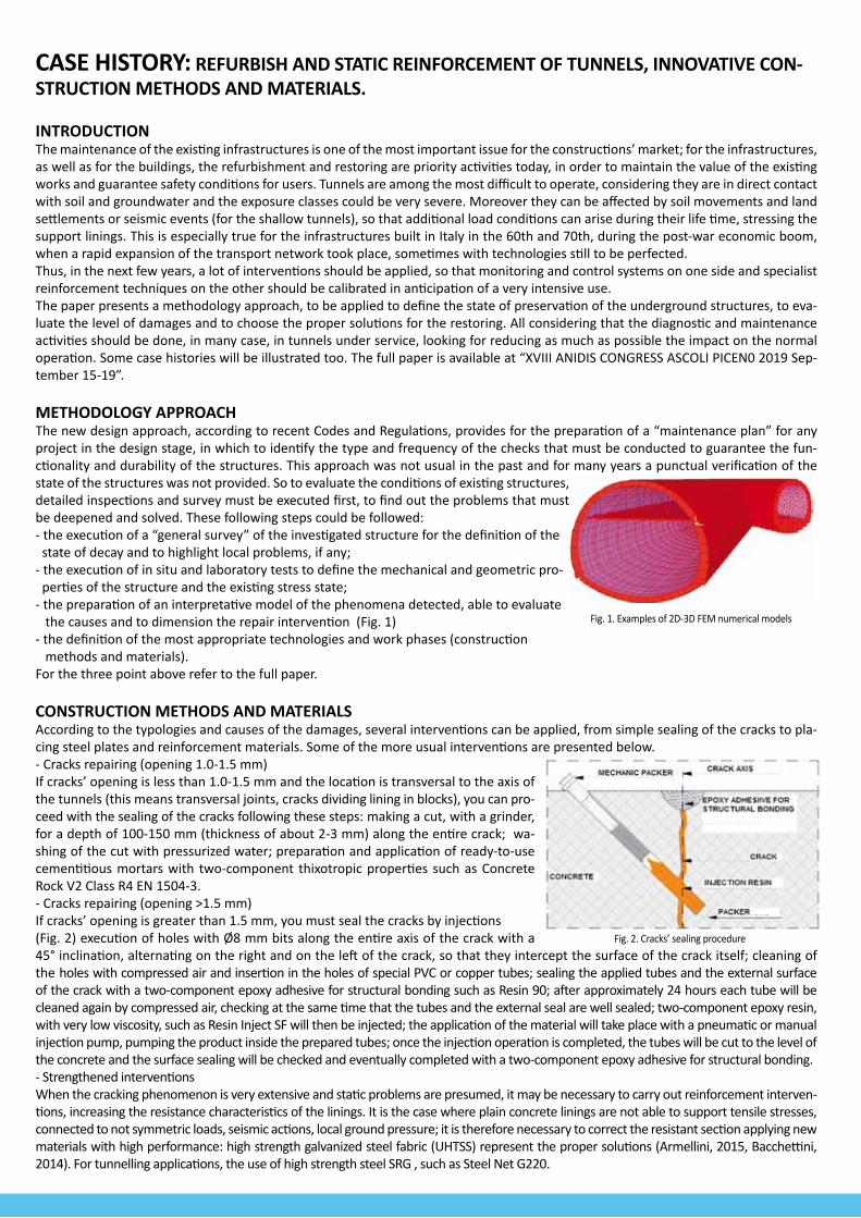
CONSTRUCTION METHODS AND MATERIALSAccording to the typologies and causes of the damages, several interventions can be applied, from simple sealing of the cracks to pla-cing steel plates and reinforcement materials. Some of the more usual interventions are presented below.- Cracks repairing (opening 1.0-1.5 mm)If cracks’ opening is less than 1.0-1.5 mm and the location is transversal to the axis of the tunnels (this means transversal joints, cracks dividing lining in blocks), you can pro-ceed with the sealing of the cracks following these steps: making a cut, with a grinder, for a depth of 100-150 mm (thickness of about 2-3 mm) along the entire crack; wa-shing of the cut with pressurized water; preparation and application of ready-to-use cementitious mortars with two-component thixotropic properties such as Concrete Rock V2 Class R4 EN 1504-3.- Cracks repairing (opening >1.5 mm)If cracks’ opening is greater than 1.5 mm, you must seal the cracks by injections (Fig. 2) execution of holes with Ø8 mm bits along the entire axis of the crack with a 45° inclination, alternating on the right and on the left of the crack, so that they intercept the surface of the crack itself; cleaning of the holes with compressed air and insertion in the holes of special PVC or copper tubes; sealing the applied tubes and the external surface of the crack with a two-component epoxy adhesive for structural bonding such as Resin 90; after approximately 24 hours each tube will be cleaned again by compressed air, checking at the same time that the tubes and the external seal are well sealed; two-component epoxy resin, with very low viscosity, such as Resin Inject SF will then be injected; the application of the material will take place with a pneumatic or manual injection pump, pumping the product inside the prepared tubes; once the injection operation is completed, the tubes will be cut to the level of the concrete and the surface sealing will be checked and eventually completed with a two-component epoxy adhesive for structural bonding.- Strengthened interventionsWhen the cracking phenomenon is very extensive and static problems are presumed, it may be necessary to carry out reinforcement interven-tions, increasing the resistance characteristics of the linings. It is the case where plain concrete linings are not able to support tensile stresses, connected to not symmetric loads, seismic actions, local ground pressure; it is therefore necessary to correct the resistant section applying new materials with high performance: high strength galvanized steel fabric (UHTSS) represent the proper solutions (Armellini, 2015, Bacchettini, 2014). For tunnelling applications, the use of high strength steel SRG , such as Steel Net G220.
Fig. 1. Examples of 2D-3D FEM numerical models
Fig. 2. Cracks’ sealing procedure
Fig. 5. A14 Highway Bologna- Taranto, Italy
Fig. 6. Strengthening of the transversal RC beams. Fig. 7. Insertion of the laminate into the steel anchorage at the fixed end.
Fig. 8. Hydraulic jack pushing the mobile steel anchorage contrasting with the steel bolted plate.
Fig. 9. Removal of the hydraulic jack and provisional anchorages 48 hours after the prestressing process.
Fig. 10. General view of the bridge after the strengthening intervention.
CASE STUDY - MOTORWAY A14 Adriatica/Bologna The technology of strengthening with pretensioned FRP lamina-tes was then applied to a real case study, namely on the girders of the Battiferro-Navile viaduct (Fig. 5) and other on the bridges of A14 in Senigallia. This bridge in Bologna, here reported, was about 40 years old and showed structural problems due to con-crete deterioration and also significant increase of traffic loads. The intervention has regarded both main longitudinal PRC be-ams and transversal RC beams (Fig. 6) . A ply of carbon laminate was applied at the bottom of the transversal RC beams as flexu-ral strengthening. An additional ply of unidirectional carbon FRP was U-wrapped at both ends of these beams to prevent shear failure and partially contribute to flexural strengthening ancho-rage. The PRC longitudinal beams were strengthened by pre-stressed carbon laminates with steel plates anchorages at both ends (Fig. 7-8) . Each laminate was pretensioned with a force of 120 kN, evaluated measuring the elongation of the laminates du-ring pretensionig. The applied pretensioning force corresponds to a strain of 0.6%. In Fig. 9-10 a view of job site.

CASE HISTORY: STRENGTHENING OF BRIDGES WITH PRETENSIONED FRP LAMINATES, EXPERIMENTAL INVESTIGATION AND A CASE STUDY.INTRODUCTIONExternally bonded Fiber Reinforced Polymer (FRP) sheets are currently used to repair and strengthen existing Reinforced Concrete (RC) and Prestressed Reinforced Concrete (PRC) structures. A number of experimental programs and analytical studies have been developed in the last years at the University of Padova on flexural (Pellegrino and Modena 2009a), shear (Pellegrino and Modena 2002, 2006, 2008), confinement (Pellegrino and Modena 2010) and bond behaviour (Pellegrino et al. 2008, Pellegrino and Modena 2009b) of FRP strengthened elements. The method of strengthening and/or reinforcing RC structures with FRP sheets/laminates as externally bonded reinforcement can be extended when FRP strengthening is prestressed before they are applied to the concrete surface. Following this technique, a unidirectional FRP sheet/laminate is first pre- tensioned and applied to the tension face of the beam, the two far ends of the composite are anchored once the adhesive has fully hardened, and the FRP laminate is then tran-sformed into prestressing element (Triantafillou et al. 1992). Few experimental tests (El-Hacha et al. 2003, 2004, Tan et al. 2003, Triantafillou et al. 1992, Wight et al. 2001) have been developed on specimens strengthened with pre- tensioned FRP laminates and almost all these experiments have been on reduced-scale elements. Furthermore, very few papers are available on the efficiency of various kinds of end-anchorage devices, to develop the strength of the composite laminates and preclude failure by debonding of the composite systems from their concrete support (e.g. Brena et al. 2003).In this paper, firstly, the results of experimental testing of real-scale RC and PRC beams strengthened in flexure with ordinary and pre-tensioned FRP laminates are given (Pellegrino and Modena 2009) and then a practical application of the same FRP pre- ten-sioning technique for strengthening of the girders of the Battiferro – Navile viaduct (A14 Highway Bologna-Taranto, Italy) is shown. The full paper is available at “Bridge Maintenance, Safety, Management, Resilience and Sustainability – Biondini & Frangopol (Eds) © 2012 Taylor & Francis Group, London, ISBN 978-0-415-62124-3”.
EXPERIMENTAL PROGRAMBefore using the pretensioning technique for infiled practical applications for bridge strengthening, a specific experimental investigation on the same system was developed.Five real-scale beams (four RC beams and one PRC beamwith pre-tensioned internal strands) 10 m long, of cross-section 300x500 mm, were tested. The load scheme, dimensions and details of the internal reinforcement of the beams and beam in the Lab. are shown in Figure 1and 2. European standards (EN 12390 2003, EN 10002 2004, EN 15630 2004) were followed for basic materials tests on concrete and steel.Unidirectional Carbon Fiber Reinforced Polymer (CFRP) pultruded laminates of 1.2x100 mm and 1.2x80 mm were used for ordinary and pre-tensioned strengthening, respectively. Tensile tests on CFRP laminate were developed according to ASTM-D3039 standard. The beams were equipped with a minimum of three strain-gauges in the middle cross-section, at the upper and bottom faces and laterally at the longitudinal reinforcement position, and three linear variable differential transformers (LVDT) at midspan and at bearin-gs. Other strain gauges were distributed along the tensile face of the beam to monitor strain distribution. 10 mm strain-gauges, type L Y11- 10/120, were used to obtain FRP strain. The loading in the beam was applied by a 500 kN capacity hydraulic jack with manual control. Test of the basic materials (concrete, reinforcing and prestressing steel) were developed. The RC-N beam was strengthened with ordinary CFRP laminate. One end of the laminate was U-jacketed with CFRP sheets and the other, at which a series of strain gau-ges was applied, was free. Hence delamination occurs at the instrumented end of the RC-N beam. The RC-EA beam was strengthened with ordinary CFRP laminate at the bottom, but mechanical steel bolted plate anchorages were used at both ends. The RC-PrEA beam was strengthened with pre- tensioned CFRPlaminate (see Fig. 3) . Prestressing strains of 0.6% and 0.4% were appliedto thelaminate, respectively for RC-PrEA and PRC-PrEA beams. The PRC-PrEA beam was the only PRC beam having the same concrete and ordinary steel mechanical characteristics and the same geometry as the other beams. (see Figs. 1 and 2)
EXPERIMENTAL RESULTSFigure 4 shows load vs. midspan deflection diagrams for the five beams until FRP delamination (the final part of the diagram, with delaminated FRP and only ancho-rages resisting, was not included). The RC-C diagram showed the typical flexural behavior of RC beams with pre-cracked, post-cracked and post-yielded stages. The RC-N diagram shows brittle behavior, due to sudden delamination of the CFRP lami-nate, starting from the free end and propagating toward the other end. The RC-EA diagram shows similar behaviour, but with a higher value of the ultimate load, due to the presence of end- anchorage devices. Failure of beams RC-PrEA and PRC-PrEA was again due to delamination of the CFRP, but pre-stressing and end-anchorage action delayed complete failure. A relevant increment in the ultimate load and an increment of the load at which the first crack appeared occurred for beams with pre-tensioned laminates (RC-PrEA, PRC-PrEA) with respect to the control beam (RC-C), due to the compressive axial force transferred by pre-tensioning and, for beam PRC-PrEA, also by internal strands. Therefore, pretensioning allows better utilization of the laminate with strain values very near the ultimate.
Fig. 1. Load configuration (dimensions in mm) and cross section of RC beams (left) and PRC
beam (right).
Fig. 2. Typical beam before execution of test
Fig. 3. RC-PrEA beam prestressed.
Fig. 4. Load vs. deflection diagrams for the five beams.
CASE HISTORY: REFURBISH AND STATIC REINFORCEMENT OF TUNNELS, INNOVATIVE CON-STRUCTION METHODS AND MATERIALS.
INTRODUCTIONThe maintenance of the existing infrastructures is one of the most important issue for the constructions’ market; for the infrastructures, as well as for the buildings, the refurbishment and restoring are priority activities today, in order to maintain the value of the existing works and guarantee safety conditions for users. Tunnels are among the most difficult to operate, considering they are in direct contact with soil and groundwater and the exposure classes could be very severe. Moreover they can be affected by soil movements and land settlements or seismic events (for the shallow tunnels), so that additional load conditions can arise during their life time, stressing the support linings. This is especially true for the infrastructures built in Italy in the 60th and 70th, during the post-war economic boom, when a rapid expansion of the transport network took place, sometimes with technologies still to be perfected.Thus, in the next few years, a lot of interventions should be applied, so that monitoring and control systems on one side and specialist reinforcement techniques on the other should be calibrated in anticipation of a very intensive use.The paper presents a methodology approach, to be applied to define the state of preservation of the underground structures, to eva-luate the level of damages and to choose the proper solutions for the restoring. All considering that the diagnostic and maintenance activities should be done, in many case, in tunnels under service, looking for reducing as much as possible the impact on the normal operation. Some case histories will be illustrated too. The full paper is available at “XVIII ANIDIS CONGRESS ASCOLI PICEN0 2019 Sep-tember 15-19”.
METHODOLOGY APPROACHThe new design approach, according to recent Codes and Regulations, provides for the preparation of a “maintenance plan” for any project in the design stage, in which to identify the type and frequency of the checks that must be conducted to guarantee the fun-ctionality and durability of the structures. This approach was not usual in the past and for many years a punctual verification of the state of the structures was not provided. So to evaluate the conditions of existing structures, detailed inspections and survey must be executed first, to find out the problems that must be deepened and solved. These following steps could be followed: - the execution of a “general survey” of the investigated structure for the definition of the state of decay and to highlight local problems, if any;- the execution of in situ and laboratory tests to define the mechanical and geometric pro- perties of the structure and the existing stress state;- the preparation of an interpretative model of the phenomena detected, able to evaluate the causes and to dimension the repair intervention (Fig. 1) - the definition of the most appropriate technologies and work phases (construction methods and materials).For the three point above refer to the full paper.
CONSTRUCTION METHODS AND MATERIALSAccording to the typologies and causes of the damages, several interventions can be applied, from simple sealing of the cracks to pla-cing steel plates and reinforcement materials. Some of the more usual interventions are presented below.- Cracks repairing (opening 1.0-1.5 mm)If cracks’ opening is less than 1.0-1.5 mm and the location is transversal to the axis of the tunnels (this means transversal joints, cracks dividing lining in blocks), you can pro-ceed with the sealing of the cracks following these steps: making a cut, with a grinder, for a depth of 100-150 mm (thickness of about 2-3 mm) along the entire crack; wa-shing of the cut with pressurized water; preparation and application of ready-to-use cementitious mortars with two-component thixotropic properties such as Concrete Rock V2 Class R4 EN 1504-3.- Cracks repairing (opening >1.5 mm)If cracks’ opening is greater than 1.5 mm, you must seal the cracks by injections (Fig. 2) execution of holes with Ø8 mm bits along the entire axis of the crack with a 45° inclination, alternating on the right and on the left of the crack, so that they intercept the surface of the crack itself; cleaning of the holes with compressed air and insertion in the holes of special PVC or copper tubes; sealing the applied tubes and the external surface of the crack with a two-component epoxy adhesive for structural bonding such as Resin 90; after approximately 24 hours each tube will be cleaned again by compressed air, checking at the same time that the tubes and the external seal are well sealed; two-component epoxy resin, with very low viscosity, such as Resin Inject SF will then be injected; the application of the material will take place with a pneumatic or manual injection pump, pumping the product inside the prepared tubes; once the injection operation is completed, the tubes will be cut to the level of the concrete and the surface sealing will be checked and eventually completed with a two-component epoxy adhesive for structural bonding.- Strengthened interventionsWhen the cracking phenomenon is very extensive and static problems are presumed, it may be necessary to carry out reinforcement interven-tions, increasing the resistance characteristics of the linings. It is the case where plain concrete linings are not able to support tensile stresses, connected to not symmetric loads, seismic actions, local ground pressure; it is therefore necessary to correct the resistant section applying new materials with high performance: high strength galvanized steel fabric (UHTSS) represent the proper solutions (Armellini, 2015, Bacchettini, 2014). For tunnelling applications, the use of high strength steel SRG , such as Steel Net G220.
Fig. 1. Examples of 2D-3D FEM numerical models
Fig. 2. Cracks’ sealing procedure
Fig. 5. A14 Highway Bologna- Taranto, Italy
Fig. 6. Strengthening of the transversal RC beams. Fig. 7. Insertion of the laminate into the steel anchorage at the fixed end.
Fig. 8. Hydraulic jack pushing the mobile steel anchorage contrasting with the steel bolted plate.
Fig. 9. Removal of the hydraulic jack and provisional anchorages 48 hours after the prestressing process.
Fig. 10. General view of the bridge after the strengthening intervention.
CASE STUDY - MOTORWAY A14 Adriatica/Bologna The technology of strengthening with pretensioned FRP lamina-tes was then applied to a real case study, namely on the girders of the Battiferro-Navile viaduct (Fig. 5) and other on the bridges of A14 in Senigallia. This bridge in Bologna, here reported, was about 40 years old and showed structural problems due to con-crete deterioration and also significant increase of traffic loads. The intervention has regarded both main longitudinal PRC be-ams and transversal RC beams (Fig. 6) . A ply of carbon laminate was applied at the bottom of the transversal RC beams as flexu-ral strengthening. An additional ply of unidirectional carbon FRP was U-wrapped at both ends of these beams to prevent shear failure and partially contribute to flexural strengthening ancho-rage. The PRC longitudinal beams were strengthened by pre-stressed carbon laminates with steel plates anchorages at both ends (Fig. 7-8) . Each laminate was pretensioned with a force of 120 kN, evaluated measuring the elongation of the laminates du-ring pretensionig. The applied pretensioning force corresponds to a strain of 0.6%. In Fig. 9-10 a view of job site.

Bridge San Giuliano - Mestre Ve
Viaducts motorway A14 Adriatica
Bridge on Po river Piacenza
ANAS Viaduct Vernalde S.S.V. 17 Isernia
Tunnel motorway A1 Bologna-Firenze Roads SP 20 Verona
TECHNOLOGIES FOR SAFE AND LONG LASTING INFRASTRUCTURES
BRIDGES VIADUCTSTUNNELS
®
Glass fiber grid ARMOPHALT GST for asphalt reinforcement.
Excellent adhesion asphalt interlayers, high strain resistance under heavy cyclic loadings, avoid reflection cracking, asphalt thickness reduction, strong reduction of maintenance costs, fast and easy application.
Waterproofing and wearing system MATACRYL for bridges, parkings.
Very few limitations for installation at varying temperatures; rapid setting and curing minimises costly possesion & facilitates almost immediate use; non absorbent and impermeable; high resistance and durability; resilient and even resist indentation by ballast; tenacious bond to concrete and steel surface; high crack bridging even at below sub zero temperatures; chemical (fusion) bonding between subsequent coatings minimises chances of any debonding; seamless protection; high resistance of tackcoat to work traffic.
Sliding pendulum isolators and bearings HISLIDE for bridges HIRUN International Division.
Viaduct San Marino Highways Ascoli Mare
Copyright 2021– All rights reserved. Rev. 01/21
G&P intech s.r.l - via Retrone 39 - 36077 Altavilla Vicentina (VI) - ITALYPh. +39.0444.522797 - Fax +39.0444.349110 E mail: [email protected] - www.gpintech.com
®
Headquarters
ROADS
fabric, is a very flexible solution, able to increase the tensile stren-gth capacity of the linings with a reduced variation of the thickness, so to preserve the clearance of the section. The Steel Net G220 is embedded into a two-component mortar layer Concrete Rock V2, after removing few of the existing concrete. These are the execution phases: removal of a concrete thickness of about 45-50mm (not greater than the cover for reinforced concre-te); cleaning the surfaces to reinforce, removing any damaged or incoherent parts; roughening of the concrete surface and restora-tion of any missing volumes with adequate mortars; installation of a first layer of two-component mortar Class R4, such as Concrete Rock V2, using a trowel, for a layer of 15-20 mm; positioning of the layer of fabric in UHTSS galvanized steel such as Steel Net G220, into the fresh mortar, transversal and/or longitudinal, taking care to perfectly impregnate the fabric avoiding the formation of wrin-kles or bubbles; installation of the steel connectors, such as SFIX G 12, drilling the concrete lining and injecting special resin such as Resin RG380 for grouting the connecting elements; installation of the final layer of two-component mortar R4, such as Concrete Rock V2, reaching a protective thickness against a possible fire, equal to about 30- 35 mm (total mortar thickness 50-60 mm).In this way, part of the existing lining is replaced with high perfor-mance material, able to support tensile stresses and to increase bending capacity.Figure 3 represents a typical intervention: in order to cover cracking area, a longitudinal and some transversal (each 1.00 m) Steel Net G220 fabrics are placed, sewing the crack.
Fig. 4. UHTSS Steel Net G220’s application
Fig. 5. Systematic lining reinforcement by Steel Net G220 and detailing of connector SFIX G 12
Fig. 3. UHTSS Steel Net G220 fabric intervention
CASE STUDY MOTORWAY A1 Bologna-Firenze The Fig. 4-5 show a reinforcement with UHTSS galvanized steel fa-bric Steel Net G220, to repair part of a tunnel crown affected by cracks: the 300 mm tape is unrolled and positioned with specific mortars on the intrados of the tunnel’s lining, in correspondence of the cracks, mechanically fixed with connectors and embedded in a layer of high performance mortar Concrete Rock V2.Some of the interventions described above have been applied for the restoration of tunnels part of the A1 Bologna-Firenze Mo-torway (Lunardi et al. 2008) and a tunnel near Firenze junction (Impruneta). Steel Net G220 as SRG can be used for systematic reinforcement too, if the resistance of plain concrete linings is to be increased to support unexpected loads or seismic conditions. The steel fabrics are positioned along the entire profile of the tun-nel intrados at a variable distance, normally in the range 1.20-1.80 m depending on the increase in resistance to be applied. A 3D SAP2000 model has allowed to evaluate in detail the state of stress present in the node and to dimension the necessary reinfor-cement. The model’s results were compared and calibrated with the results of doorstopper tests, executed in the lining in the most significant points length.
PADUA: 21/08/29 - 21/09/01
TECHNOLOGIES FOR INFRASTRUCTURES
Wuhu Yangtze River Bridge
congress
WE WILL ATTEND