case study for insulation selection for a deepwater development
TRANSCRIPT

Case Study for Insulation
Selection for a Deepwater
Development
Mustafa Mahmood, Flow Assurance Manager
Kuala Lumpur, 3rd October 2012

Contents
1. Introduction / Project Background
2. Concept Selection
3. Flow Assurance
4. Conclusions
Case Study for Insulation Selection for
Deepwater Development

Introduction / Project Background
The Case Study presented is for a deepwater oil
production system, tied-back to an existing FPSO.
Project Data
• Water Depth 1400 m
• Three production centres (P1,P2,P3) / manifolds
• 20 km subsea tie-back to an existing FPSO
• 2x7” flexible risers design
• Two 8” production flowlines in a piggable loop
Case Study for Insulation Selection for
Deepwater Development
Case Study for Insulation Selection for
Deepwater Development

Fluid Data
Crude production from the subsea wells will come pre-
dominantly from 4 different reservoirs. The fluidproperties available for the 4 reservoirs are presented
in the table below.
Reservoir Reservoir
Temp
(oC)
GOR
(SCF/STB)
APIo Dead Oil
WAT
(oC)
Live Oil
WAT
(oC)
Dead Oil
Pour
Point
(oC)
Live Oil
Pour
Point
(oC)
1 44– 53 655-782 33.4– 37.6
2 47–54 802-813 35.3-35.7 2 to 12
3 57-64 672-773 31.5-32.1 18 to 29 12 to 15 < 0
4 61-65 560-709 28.5-31.7 17 to 31 26 to 28 12 to 18 < 0
Case Study for Insulation Selection for
Deepwater Development
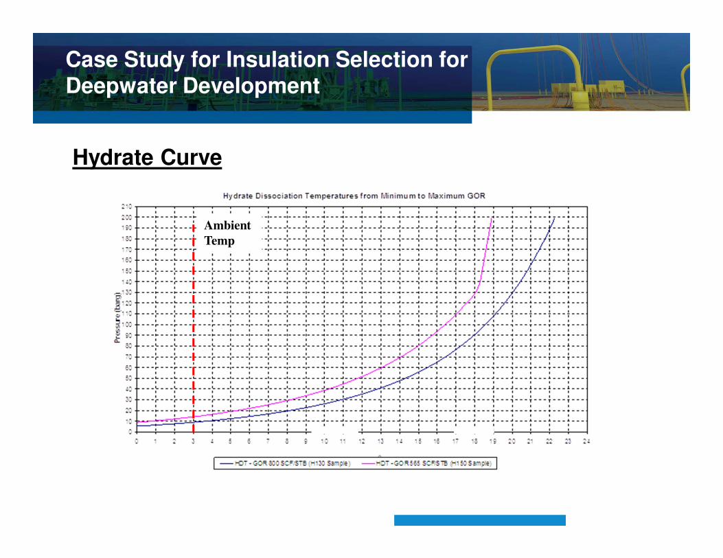
Hydrate Curve
Ambient
Temp
Case Study for Insulation Selection for
Deepwater Development

Main flow assurance challenges being :
• hydrate,
• wax
• gel management.
For this Case Study:
Dead Oil WAT = 31 deg.C, (Steady State Conditions)
Dead Oil Pour Point = 18 deg.C (Cooldown Conditions)
Hydrates at 18 deg.C or less. (Cooldown Conditions)
Dead Oil Gel Strength = 250 Pa
Case Study for Insulation Selection for
Deepwater Development

Concept SelectionConcept Screening Workshop narrowed the number of concepts to two
concepts.
a)Dual Pipe in Pipe (PIP) flowlines in piggable loop configuration.
b)Dual glass flake syntactic polyurethane (GSPU) Insulated
flowlines
Insulated Flexibles risers were considered for both options.
A piggable loop pipeline configuration employed to cater for turndown
flowrates, hot oil flushing ,the provision for depressuring either side of a
hydrate blockage and inspection pigging etc.
Only initial concern was Reel-Lay for the PIP option with regional based
installation contractors.
Case Study for Insulation Selection for
Deepwater Development

Case Study for Insulation Selection for
Deepwater Development

Flow Assurance – Steady State
The Dual Flowlines options considered with PIP (U=1.2 W/m2.K)
production flowlines or 3” GPSU (U=2.9 W/m2.K) insulated
flowlines and insulated flexible risers (U=2.6 W/m2.K).
The P3 to P2 section was considered to be the most critical from a
steady state point of view since it would experience the lowest
flowrates
Flowrates from P3 could be low enough to justify operation of only
a single flowline from P3 with the other section remaining diesel
filled.
The steady state results for Single and Dual flowlines operating for
the P3 to P2 sections of the flow loop are presented below for the
PIP and GSPU flowline insulation options.
Case Study for Insulation Selection for
Deepwater Development

PIP Single / Dual Flowlines Outlet Temperatures at P2
P3 to P2
Case Study for Insulation Selection for
Deepwater Development

GSPU Single / Dual Flowlines Outlet Temperatures at P2
Case Study for Insulation Selection for
Deepwater Development
P3 to P2

GSPU Single Flowline Temperature Profile
.P3 P2 P1
Case Study for Insulation Selection for
Deepwater Development

Flow Assurance P3 to P-2 Steady State
A single PIP flowline operating from P3 to P2 operating PIP
maintains fluid temperatures above WAT = 31 deg.C.
For Dual PIP flowlines operating, fluid temperatures fall below
31 deg.C for years 15 to 20 and will require wax inhibition.
Dual GSPU production flowlines cannot maintain fluid
temperatures above WAT = 31 deg.C and will require wax
inhibition continuously from year 1.
For a single GSPU flowline operating from P3 to P2 fluid
temperatures fall below 31 deg.C for years 15 to 20 and would
require wax inhibition.
The riser section for years 1 & 2 fall below 31 deg.C and thus
chemical injection would also be required in these years.
Case Study for Insulation Selection for
Deepwater Development

Flow Assurance - Operating / Insulation Philosophy
Under upset conditions such as unplanned shutdowns, the insulation
is to provide sufficient cooldown time to flush the production flowline
system with diesel/stabilized inhibited crude. This then mitigates any
gel or hydrate risk in the flowlines during shutdowns.
Flush existing system prior to flushing new development.
Use existing flushing pumps or propose new flushing rate.
Cooldown times of 22.5 hrs or 11.1 hrs are required for flushing rates
of 100m3/hr (existing) or 200m3/hr .
Case Study for Insulation Selection for
Deepwater Development
Flow Assurance - Cooldown Analysis
Cooldown plots presented for:
• GSPU flowline (single flowline in operation between P3 to P2)
• PIP flowline (single flowline in operation between P3 to P2)
• PIP flowline (dual flowline in operation between P3 to P2)
• PIP flowline (dual flowline in operation between P3 to P2) +
Detailed Riser
Case Study for Insulation Selection for
Deepwater Development

Flow Assurance - Cooldown Analysis
Year 1 GSPU flowline (single flowline in operation between P3 to P2)
P3 to P2 P2 to P1 P1 to Riser
Case Study for Insulation Selection for
Deepwater Development

Flow Assurance - Cooldown Analysis
PIP flowline (single flowline in operation between P3 to P2)
P3 to P2 P2 to P1 P1 to Riser
Case Study for Insulation Selection for
Deepwater Development

Flow Assurance - Cooldown Analysis
PIP flowline (dual flowline in operation between P3 to P2)
P3 to P2 P2 to P1 P1 to Riser
Case Study for Insulation Selection for
Deepwater Development

Flow Assurance - Cooldown Analysis
PIP flowline (dual flowline in operation between P3 to P2) + Detailed Riser
P3 to P2 P2 to P1 P1 to Riser
Case Study for Insulation Selection for
Deepwater Development
Case Study Conclusions
• PIP system provides a robust solution and steady state operatingconditions which do not require wax inhibition until Year 15 onwards forthe dual flowlines operating between P3 and P2.
• This option was recommended.
• GSPU option requires steady state single flowline operation between P3and P2 and continuous wax inhibition for Yrs 1 & 2 & 15 to 20.
• Flushing rate should be increased from 100m3/hr to 200m3/hr to provide amore acceptable cooldown requirement.
• The PIP can comfortably meet cooldown requirements however the GSPUcan just meet cooldown requirements with flushing operations.
• For GSPU option flushing operations of the diesel filled section betweenP3 and P2 result in short periods (1 to 2 hours) of operation in the hydrateand gelation region which is normally unacceptable.
• Riser cooldown also meets flushing requirements
Case Study for Insulation Selection for
Deepwater Development