carver high performing arts addition - aldine isd · carver high performing arts addition ......
TRANSCRIPT
ADDENDA NO. ONE
CARVER HIGH PERFORMING ARTS
ADDITION
ALDINE INDEPENDENT SCHOOL DISTRICT
HOUSTON,TEXAS
MOSELEY ASSOCIATES INC., ARCHITECTS
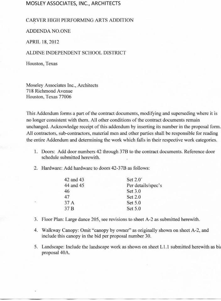
MOSLEY ASSOCIATES, INC., ARCHITECTS
CARVER HIGH PERFORMING ARTS ADDITION
ADDENDA NO.ONE
APRIL 18, 2012
ALDINE INDEPENDENT SCHOOL DISTRICT
Houston, Texas
Moseley Associates Inc., Architects718 Richmond AvenueHouston, Texas 77006
This Addendum forms a part of the contract documents, modifying and superseding where it isno longer consistent with them. All other conditions of the contract documents remainunchanged. Acknowledge receipt of this addendum by inserting its number in the proposal form.All contractors, sub-contractors, material men and other parties shall be responsible for readingthe entire Addendum and determining the work which falls in their respective work categories.
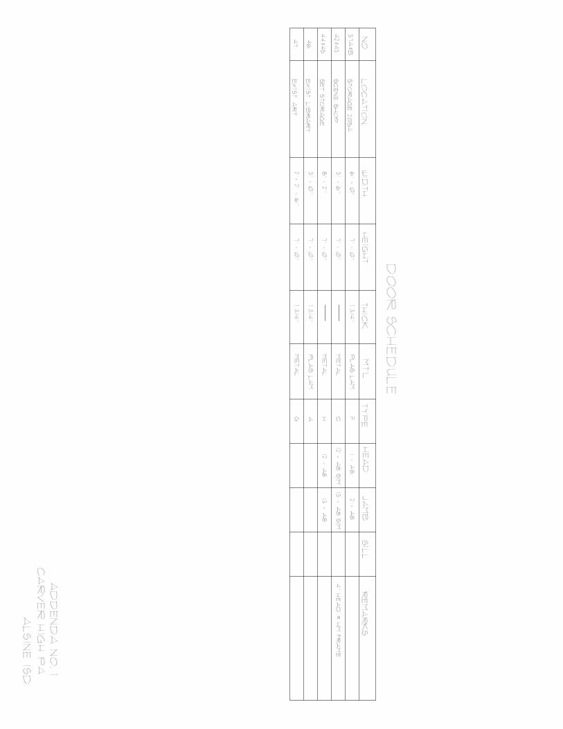
1. Doors: Add door numbers 42 through 37B to the contract documents. Reference doorschedule submitted herewith.
2. Hardware: Add hardware to doors 42-37B as follows:
42 and 43 Set 2.0'44 and 45 Per details/spec's46 Set 3.047 Set 2.037 A Set 5.037 B Set 5.0
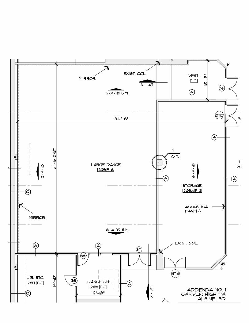
3. Floor Plan: Large dance 205, see revisions to sheet A-2 as submitted herewith.
4. Walkway Canopy: Omit "canopy by owner" as originally shown on sheet A-2, andinclude this canopy in the bid per proposal number 30.
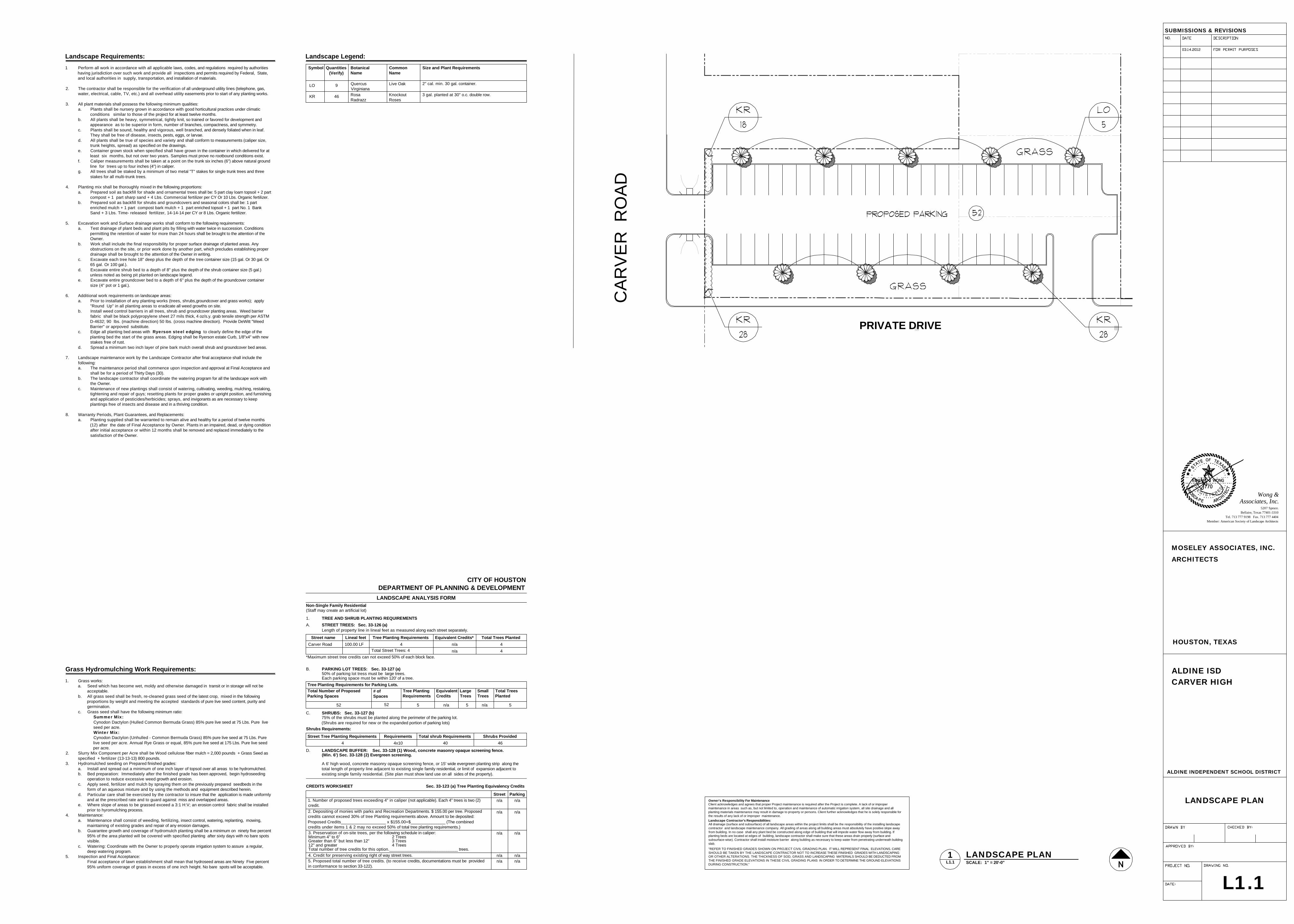
5. Landscape: Include the landscape work as shown on sheet Ll.l submitted herewith as bicproposal 40A.
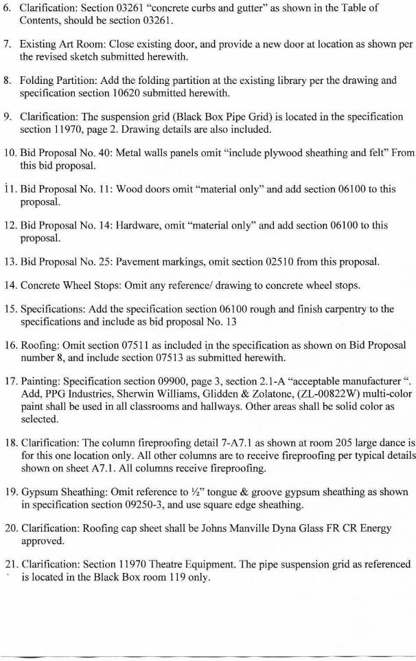
6. Clarification: Section 03261 "concrete curbs and gutter" as shown in the Table ofContents, should be section 03261.
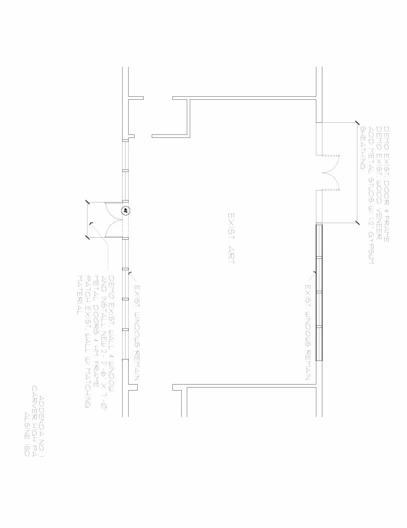
7. Existing Art Room: Close existing door, and provide a new door at location as shown perthe revised sketch submitted herewith.
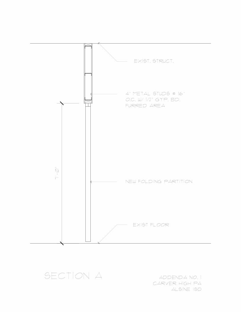
8. Folding Partition: Add the folding partition at the existing library per the drawing andspecification section 10620 submitted herewith.
9. Clarification: The suspension grid (Black Box Pipe Grid) is located in the specificationsection 11970, page 2. Drawing details are also included.
10. Bid Proposal No. 40: Metal walls panels omit "include plywood sheathing and felt" Fromthis bid proposal.
11. Bid Proposal No. 11: Wood doors omit "material only" and add section 06100 to thisproposal.
12. Bid Proposal No. 14: Hardware, omit "material only" and add section 06100 to thisproposal.
13. Bid Proposal No. 25: Pavement markings, omit section 02510 from this proposal.
14. Concrete Wheel Stops: Omit any reference/ drawing to concrete wheel stops.
15. Specifications: Add the specification section 06100 rough and finish carpentry to thespecifications and include as bid proposal No. 13
16. Roofing: Omit section 07511 as included in the specification as shown on Bid Proposalnumber 8, and include section 07513 as submitted herewith.
17. Painting: Specification section 09900, page 3, section 2.1-A "acceptable manufacturer ".Add, PPG Industries, Sherwin Williams, Glidden & Zolatone, (ZL-00822W) multi-colorpaint shall be used in all classrooms and hallways. Other areas shall be solid color asselected.
18. Clarification: The column fireproofing detail 7-A7.1 as shown at room 205 large dance isfor this one location only. All other columns are to receive fireproofing per typical detailsshown on sheet A7.1. All columns receive fireproofing.
19. Gypsum Sheathing: Omit reference to '/a" tongue & groove gypsum sheathing as shownin specification section 09250-3, and use square edge sheathing.
20. Clarification: Roofing cap sheet shall be Johns Manville Dyna Glass FR CR Energyapproved.
21. Clarification: Section 11970 Theatre Equipment. The pipe suspension grid as referencedis located in the Black Box room 119 only.
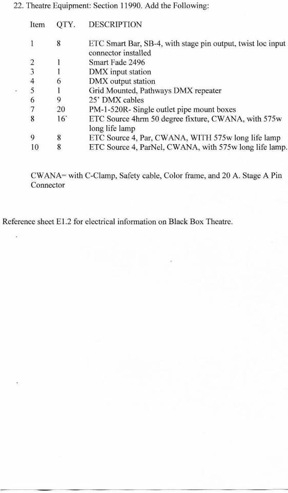
22. Theatre Equipment: Section 11990. Add the Following:
Item QTY. DESCRIPTION
1 8 ETC Smart Bar, SB-4, with stage pin output, twist loc inputconnector installed
2 1 Smart Fade 24963 1 DMX input station4 6 DMX output station5 1 Grid Mounted, Pathways DMX repeater6 9 25' DMX cables7 20 PM-1-520R-Single outlet pipe mount boxes8 16^ ETC Source 4hrm 50 degree fixture, CWANA, with 575w
long life lamp9 8 ETC Source 4, Par, CWANA, WITH 575w long life lamp10 8 ETC Source 4, ParNel, CWANA, with 575w long life lamp.
CWANA= with C-Clamp, Safety cable, Color frame, and 20 A. Stage A PinConnector
Reference sheet El.2 for electrical information on Black Box Theatre.

SECTION 06100
ROUGH & FINISH CARPENTRY
1 PART ONE - GENERAL
1.1 COORDINATION
A. Drawings and General provisions of the Contract including General andSupplementary Conditions and Division 1 Specification Sections apply to thisSection.
1.2 WORK INCLUDED
A. Provide and install all rough carpentry, formwork, wood framing, blocking,plywood sheathing, wood decking, wood furring, hardboard and related fastenersas indicated in the drawings or as required to complete the indicatedconstruction.
B. Provide hardwood trim.
C. Roofing perimeter wood blocking and miscellaneous nailers.
D. Install plastic clad wood doors, millwork, wood trim, wood sills, plywood wallpanels for telephone/electrical, and all related hardware and fasteners.
E. Install finish hardware at doors.
F. Prepare finish wood items for painting or staining.
1.3 RELATED SECTIONS
A. Section 03310 - Cast in place concrete
B. Section 06220 - Millwork
C. Section08221 - Plastic clad wood doors
D. Section 09910- Painting and staining
E. Section 08710-Finish Hardware
1.4SUBMITTALS
06100-1
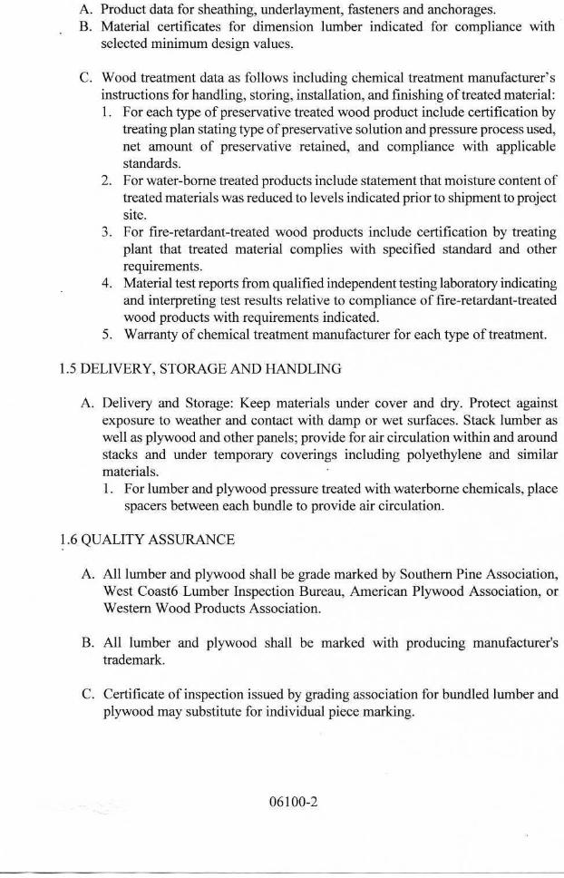
A. Product data for sheathing, underlayment, fasteners and anchorages.B. Material certificates for dimension lumber indicated for compliance with
selected minimum design values.
C. Wood treatment data as follows including chemical treatment manufacturer'sinstructions for handling, storing, installation, and finishing of treated material:1. For each type of preservative treated wood product include certification by
treating plan stating type of preservative solution and pressure process used,net amount of preservative retained, and compliance with applicablestandards.
2. For water-borne treated products include statement that moisture content oftreated materials was reduced to levels indicated prior to shipment to projectsite.
3. For fire-retardant-treated wood products include certification by treatingplant that treated material complies with specified standard and otherrequirements.
4. Material test reports from qualified independent testing laboratory indicatingand interpreting test results relative to compliance of fire-retardant-treatedwood products with requirements indicated.
5. Warranty of chemical treatment manufacturer for each type of treatment.
1.5 DELIVERY, STORAGE AND HANDLING
A. Delivery and Storage: Keep materials under cover and dry. Protect againstexposure to weather and contact with damp or wet surfaces. Stack lumber aswell as plywood and other panels; provide for air circulation within and aroundstacks and under temporary coverings including polyethylene and similarmaterials.1. For lumber and plywood pressure treated with waterborne chemicals, place
spacers between each bundle to provide air circulation.
1.6 QUALITY ASSURANCE
A. All lumber and plywood shall be grade marked by Southern Pine Association,West Coast6 Lumber Inspection Bureau, American Plywood Association, orWestern Wood Products Association.
B. All lumber and plywood shall be marked with producing manufacturer'strademark.
C. Certificate of inspection issued by grading association for bundled lumber andplywood may substitute for individual piece marking.
06100-2
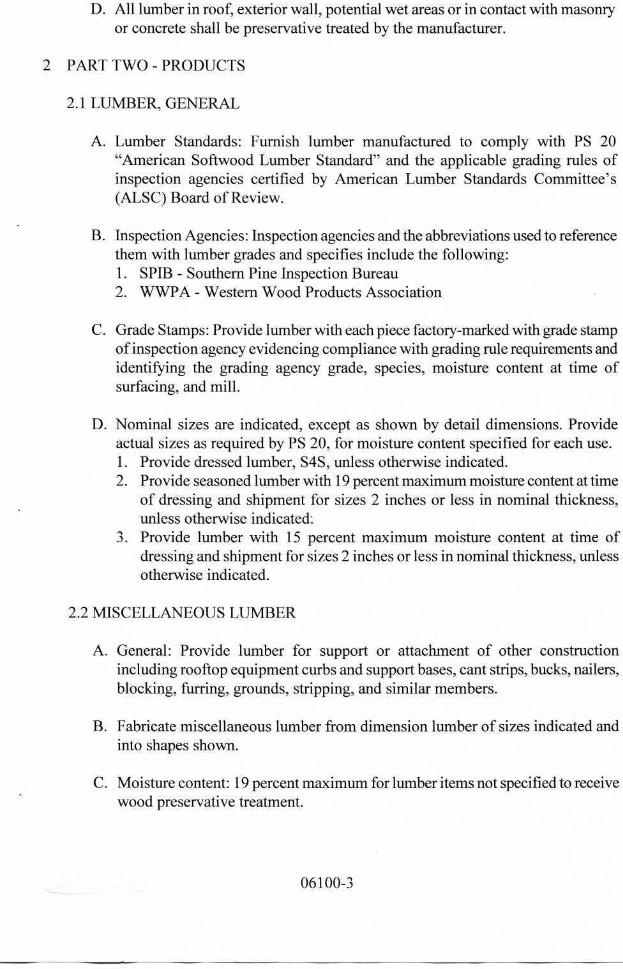
D. All lumber in roof, exterior wall, potential wet areas or in contact with masonryor concrete shall be preservative treated by the manufacturer.
2 PART TWO - PRODUCTS
2.1 LUMBER, GENERAL
A. Lumber Standards: Furnish lumber manufactured to comply with PS 20"American Softwood Lumber Standard" and the applicable grading rules ofinspection agencies certified by American Lumber Standards Committee's(ALSC) Board of Review.
B. Inspection Agencies: Inspection agencies and the abbreviations used to referencethem with lumber grades and specifies include the following:1. SPIB - Southern Pine Inspection Bureau2. WWPA - Western Wood Products Association
C. Grade Stamps: Provide lumber with each piece factory-marked with grade stampof inspection agency evidencing compliance with grading rule requirements andidentifying the grading agency grade, species, moisture content at time ofsurfacing, and mill.
D. Nominal sizes are indicated, except as shown by detail dimensions. Provideactual sizes as required by PS 20, for moisture content specified for each use.1. Provide dressed lumber, S4S, unless otherwise indicated.2. Provide seasoned lumber with 19 percent maximum moisture content at time
of dressing and shipment for sizes 2 inches or less in nominal thickness,unless otherwise indicated.
3. Provide lumber with 15 percent maximum moisture content at time ofdressing and shipment for sizes 2 inches or less in nominal thickness, unlessotherwise indicated.
2.2 MISCELLANEOUS LUMBER
A. General: Provide lumber for support or attachment of other constructionincluding rooftop equipment curbs and support bases, cant strips, bucks, nailers,blocking, furring, grounds, stripping, and similar members.
B. Fabricate miscellaneous lumber from dimension lumber of sizes indicated andinto shapes shown.
C. Moisture content: 19 percent maximum for lumber items not specified to receivewood preservative treatment.
06100-3
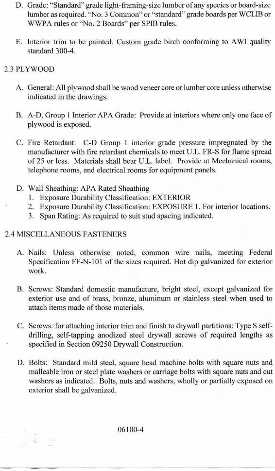
D. Grade: "Standard" grade light-framing-size lumber of any species or board-sizelumber as required. "No. 3 Common" or "standard" grade boards per WCLIB orWWPA rules or "No. 2 Boards" per SPIB rules.
E. Interior trim to be painted: Custom grade birch conforming to AWI qualitystandard 300-4.
2.3 PLYWOOD
A. General: All plywood shall be wood veneer core or lumber core unless otherwiseindicated in the drawings.
B. A-D, Group 1 Interior APA Grade: Provide at interiors where only one face ofplywood is exposed.
C. Fire Retardant: C-D Group 1 interior grade pressure impregnated by themanufacturer with fire retardant chemicals to meet U.L. FR-S for flame spreadof 25 or less. Materials shall bear U.L. label. Provide at Mechanical rooms,telephone rooms, and electrical rooms for equipment panels.
D. Wall Sheathing: APA Rated Sheathing1. Exposure Durability Classification: EXTERIOR2. Exposure Durability Classification: EXPOSURE 1. For interior locations.3. Span Rating: As required to suit stud spacing indicated.
2.4 MISCELLANEOUS FASTENERS
A. Nails: Unless otherwise noted, common wire nails, meeting FederalSpecification FF-N-101 of the sizes required. Hot dip galvanized for exteriorwork.
B. Screws: Standard domestic manufacture, bright steel, except galvanized forexterior use and of brass, bronze, aluminum or stainless steel when used toattach items made of those materials.
C. Screws: for attaching interior trim and finish to drywall partitions; Type S self-drilling, self-tapping anodized steel drywall screws of required lengths asspecified in Section 09250 Drywall Construction.
D. Bolts: Standard mild steel, square head machine bolts with square nuts andmalleable iron or steel plate washers or carriage bolts with square nuts and cutwashers as indicated. Bolts, nuts and washers, wholly or partially exposed onexterior shall be galvanized.
06100-4
E. High Strength Bolts: Machine bolts (or carriage bolts if called for on drawings)of structural grade steel with square nuts, of sizes noted on drawings.Conforming to ASTM A307.
F. Steel plates and angles: ASTM A36, galvanized after fabrication.
G. Lag Screws, shear plates and split ring connectors: Conforming to therequirements of the "National Design Specifications for Stress-Grade Lumberand its fastenings" of National Forest Products Assn.
H. Framing Anchors, Joist Hangers, etc.: Universal Anchor Co., products orsimilar devices as approved by Architect; see drawings for specified items.
I. Power Driven Inserts: Ramset, or as approved by Architect.
J. Miscellaneous Clips, Steel Assemblies: Conforming to ASTM A36.
2.5 PRESERVATIVE WOOD TREATMENT PROCESS
A. General: Where lumber or plywood is indicated as preservative-treated wood oris specified herein to be treated, comply with applicable requirements of AWPAStandards C2 (Lumber) and C9 (Plywood). Mark each treated item with theAWPB or SPIB Quality Mark Requirements.
B. Pressure-treat above-ground items with water-borne preservatives to a minimumof 0.25 pcf. For interior uses, after treatment, kiln-dry lumber and plywood to amaximum moisture content, respectively, of 19 percent and 15 percent. Treatindicated items and the following:1. Wood cants, mailers, curbs, equipment support bases, blocking, stripping,
and similar members in connection with roofing, flashing, vapor barriers,and waterproofing.
2. Wood sills, sleepers, blocking, furring, stripping, and similar concealedmembers in contact with masonry or concrete.
3. Wood framing members less than 18 inches above grade.
C. Pressure-treat wood members in contact with the ground or fresh water withwater-borne preservatives to a minimum retention of 0.40 pcf.
D. Complete fabrication of treated items prior to treatment, where possible. If cutafter treatment, coat cut surfaces to comply with AWPA M4. Inspect each pieceof lumber or plywood after drying and discard damaged or defective pieces.
E. Fire Retardant: Pressure impregnated by the manufacturer with non-combustiblefire retardant chemicals in accordance with Underwriter's Laboratories FRS Fire
06100-5
Hazard Classification. Use for framing, blocking, furring and miscellaneousconcealed lumber at interior walls and partitions. Field treat cut ends with likematerial.
3 PART THREE - EXECUTION
3.1 INSTALLATION
A. Coordination: Coordinate work with other trades and provide cutting andpatching required to accommodate the work. Verify all dimensions by takingfield measurements to ensure proper fit of all wood construction. Accurately cutframing and blocking, and fit true to line and level, avoiding unnecessary shimsand wedges.
B. Anchoring and Fastening: Use largest practicable fasteners for each type ofwork. Bolt nailers and blocking to steel, masonry or concrete members usingbolts of proportionate strength to members attached. Unless otherwise noted inthe drawings use 3/4" diameter bolts at maximum 4'-0" centers. Use concealedfasteners in finish work; set nails and use flathead countersunk screws.
C. Roof Perimeters and Nailers: Install preservative treated nailers continuous inlongest lengths practicable. Install members straight and true, without warp orcup. Use hot dip galvanized through bolts and lag bolts.
D. Door Installation: Protect finished doors prior, during and after installation.Verify that bottom and top edges of wood doors are sealed prior to installation.Hang doors plumb and true with proper fit in frames. Verify under-cutrequirements with Architect prior to installation.
E. Finish Hardware Installation: Ensure that hardware is properly marked bysupplier for each opening. Install hardware in accordance with manufacturerprinted instructions and adjust for proper working order. Install removableconstruction cores and replace with final cores only at project completion.
F. Millwork Installation: Inspect finished items for dents, scratches, marks, orother damage and make corrections or return to millwork supplier for correctivework; protect all installed work against damage.
G. Wood Blocking: Install between metal studs where wall-supported drinkingfountains, casework, railings, wall stops, toilet accessories, mirrors, TV wallbrackets and other equipment is located. Install between studs for toilet partitionsystems and toilet accessories where anchored to wall. All wood blocking inpartitions shall be fire retardant treated.
06100-6
3.2 SITE TREATMENT OF WOOD MATERIALS
A. Brush apply 1 coat of preservative treatment on wood in contact wit!cementitious materials roofing and related metal flashings, and all wet or damjareas.
END OF SECTION
06100-7
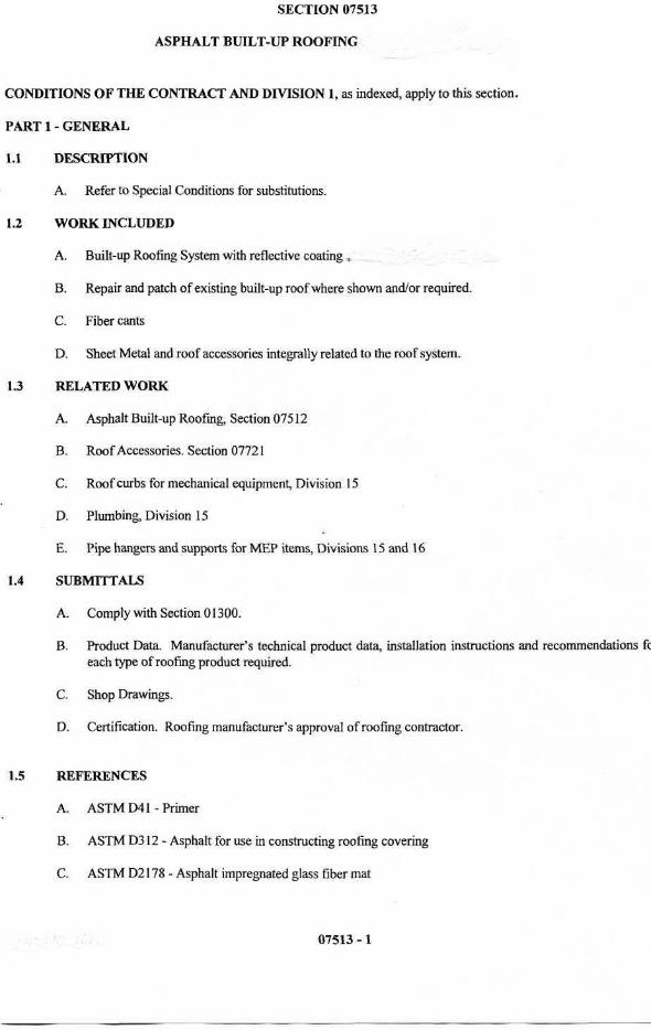
SECTION 07513
ASPHALT BUILT-UP ROOFING
CONDITIONS OF THE CONTRACT AND DIVISION 1, as indexed, apply to this section.
PART 1- GENERAL
1.1 DESCRIPTION
A. Refer to Special Conditions for substitutions.
1.2 WORK INCLUDED
A. Built-up Roofing System with reflective coating „
B. Repair and patch of existing built-up roof where shown and/or required.
C. Fiber cants
D. Sheet Metal and roof accessories integrally related to the roof system.
1.3 RELATED WORK
A. Asphalt Built-up Roofing, Section 07512
B. Roof Accessories. Section 07721
C. Roof curbs for mechanical equipment, Division 15
D. Plumbing, Division 15
E. Pipe hangers and supports for MEP items, Divisions 15 and 16
1.4 SUBMITTALS
A. Comply with Section 01300.
B. Product Data. Manufacturer's technical product data, installation instructions and recommendations fceach type of roofing product required.
C. Shop Drawings.
D. Certification. Roofing manufacturer's approval of roofing contractor.
1.5 REFERENCES
A. ASTMD41-Primer
B. ASTM D312 - Asphalt for use in constructing roofing covering
C. ASTM D2178 - Asphalt impregnated glass fiber mat
07513 -1
D. NCRA- Manual
DESIGN AND PERFORMANCE CRITERIA
A. Design Code: ASCE 7-05, Method 2 for Components and Cladding.
B. Code adopted by the City of Houston
C. Wind Speed: 105 mph
QUALITY ASSURANCE
A. Applicator: Approved by roof material manufacturer and shall be firm specializing in modified bitumenroofing with at least 5 years experience showing successful installations similar to work required for thisproject.
B. Single Responsibility: To maximum extent possible provide roofing and related materials produced byone manufacturer, except as specified or approved by Architect
C. Construction Methods: If, in Contractor's opinion, methods described in drawings and specifications arenot sufficient to prevent leaking or dripping of bitumen, notify Architect for areas of Architect'sconsideration.
DELIVERY, STORAGE, AND HANDLING
A. Comply with material manufacturer's published recommendations.
B. Deliver materials to jobsite in sealed containers with manufacturer's labels intact.
C. Completely protect insulation to keep dry and undamaged while stored at site and during installation.Replace damaged insulation with new, approved, dry material.
PROJECT CONDITIONS
A. Pre-roofing Conference: Prior to installation of roofing system, meet at project site with Installer(Roofer), installers of substrate construction (decks) and other work adjoining roof system includingpenetrating work and roof-top units, and representatives of other trades directly concerned withperformance of roofing system including Architect and Owner representatives. Review requirements,submittals, status of coordinating work, availability of materials and installation facilities, proposedinstallation schedule, requirements for inspections and testing or certifications and proposed installationrequirements for construction period extending beyond roofing installation. Discuss any need fortemporary roofing.
B. Weather Conditions: Proceed with roofing system installation only when weather conditions arefavorable and will allow work to proceed in accordance with requirements and recommendations ofmanufacturer of roofing system materials.
C. Temporary Roofing: When adverse weather conditions or other conditions make roofing systeminstallation inadvisable, and other work cannot be delayed, provide temporary roofing as approved.
DELIVERY, STORAGE AND HANDLING
A. Deliver materials to the site in manufacturer's original packaging bearing manufacturer's label,production run and date.
07513 - 2
B. Store rolled material on end on pallets and covered for protection from the weather.
C. Remove any material from the jobsite which becomes wet or damaged.
D. Uniformly distribute over the roof materials to be installed, without concentrated loads.
1.11 WARRANTY
A. The Contractor shall provide a 2-year workmanship warranty for the full roofing system from the date ofsubstantial completion for the project.
B. The manufacturer shall provide a 20-year guarantee for the roofing system from the date of substantialcompletion for the project. This guarantee shall cover both material and workmanship and shall be aNDL guarantee (have no dollar limit penal sum). This guarantee shall include a full roofing systemincluding roofing material, insulation, insulation fasteners, cants, flashing, expansion joints, metal edgeand fascia.
PART 2 -PRODUCTS
2.1 ACCEPTABLE MANUFACTURERS
A. Firestone
B. GAP
C. Garland Company
D. Johns Manville
2.2 MATERIALS
A. Base Sheet. John Manville Ventsulation or approved equal, ASTM D4897, Type II.
B. Interply. Johns Manville DynaBase or approved equal, ASTM D6163, Type I, Grade S
C. Cap Sheet: Johns Manville DynaGlass FR or approved equal ASTM D6163 Type I, Grade G
D. Coating: TG4000 (Reflects vity=83; Emissivity=.94;SRI=100)
E. Bitumen. ASTMD-312
Slope Asphalt
Up to 1/2" 190°F Type III, Steep1/2" to 3" 220°F Special Steep, Type IV
F. Base Flashing Vertical Walls/Curbs. Bituminous Flashing as approved by roofing manufacturer for a fullsystem warranty. Product: DynaFlex or approved equal ASTM D6221, Type I.
G. Fiber Cants. Of size shown.
H. Roof Metal System
07513 - 3
01 Roof Edge. Precoated sheet metal edge and flashing cold formed from minimum 50,000 p.s.i.,22 gauge galvanized steel conforming to Fed. Spec. QQS-775-C, ASTM A361 and ASTMA525. Knyar 500, Color as selected by Architect.
02 Nails, Rivets and Fasteningsa. Nails shall be hot-dip galvanized for galvanized steel.b. Rivets shall be tinned soft iron rivets.c. Aluminum - flat heat, sizes as required.
03 Sealanta. Morrison and Co., or approved, CL-50 polisobutylene; include primer as required.
04 Butyl Sealera. Where impractical to use solder at joints, comers, etc., seal with "DAP Butyl Gutter and Lap
Sealer," or "Cushion-Lock CL-50 Butyl Sealer.
05 Counter Flashing. Galvanized prepainted metal. Twenty-four (24) gauge minimum, same finishas roof edge metal.
06 Lead Flashing. ASTM B29-79 (1984), 41b. (1.82 kg) sheet lead.
J. Traffic Pad. 2 feet x 3 feet c 3/8 inch non-porous, solid rubber manufactured from recycled rubber.
PART 3-EXECUTION
3.1 INSTALLATION
A. Condition of Surfaces01 Examine roof deck, it must be smooth, dry, firm, and free from loose material. If any portion is
in poor conditions, repair before roof installation. Insure that nailers at edges and grounds forfastening roof and flashings are installed.
02 Surfaces to be covered with sheet metal shall be smooth and free from holes. Clean surfaces ofdirt, rubbish and other foreign materials before starting work. Drive projecting nails flush.
03 Verify that roof openings, curbs, pipes,, sleeves and vents thru roof are solidly set and woodnailers are in.
04 Start of work means installer accepts existing surfaces and substrates.
B. Asphalt Bitumen Heating. Heat and apply bitumen in accordance with equiviscous temperature method("EVT Method") as recommended by NRCA. Do not raise temperature above minimum normalfluid-holding temperature necessary to attain EVT (+25°F or 14°C, at point of application) morethan one hour prior to time of application. Discard bitumen which has been held at temperatureexceeding finished blowing temperature (FBT) for a period exceeding 3 hours. In no case heatbitumen to a temperature higher than 25°F (14°C) below flash point. For aggregate-surfacedpour coats of bitumen, limit application temperature to minimum required for proper embedmentof aggregate and maximum which will permit retention of a coating of weight required (dependson slope of surface). Keep kettle lid closed except when adding bitumen. Equip kettle withworking temperature.
C. Sheet Metal Work and Roof Accessories01 Install sheet metal work, roof curbs, flashings and pans. Seal around pipes and other objects
passing through roof with felt and mastic to prevent dripping.02 Strip-in metal flashings and similar metal flanges set in MBR Utility Cement with one ply of SBS
base sheet to prevent dripping.03 Cooperate with other trades making installation on roof during construction.
D. Modified Bitumen Roof System. Install in accordance with Johns Manville Spec. 3FLD and following:
07513 - 4
01 Mechanical fasten the base sheet to the light weight insulating concrete per FM 1-90requirements.
02 Do not heat asphalt above nor apply below temperatures recommended in approvedspecifications. Kettle shall be equipped with thermometer in good working order. Control toprevent overheating.
03 Install modified bituminous roofing membrane base (interplay) sheet and cap sheet according toroofing manufacturer's written instructions, starting at low point of roofing system, Extendroofing membrane sheets over and terminate beyond cants, installing as follows:a. Adhere to substrate in a solid mopping of hot roofing asphalt applied at EVT.b. Unroll roofing membrane sheets and allow them to relax for minimum time p[eriod requiredby manufacturer.
04 Apply two coats of TopGard 4000 in accordance to Manufacturer's written instructions.Minimum coverage rate of 50-70 sq. ft. per gallon.
E. Base Flashing and Accessories01 Install base flashing per roofing manufacturer's instructions for a whole system warranty.02 Install prefabricated roof expansion joint covers in accordance with manufacturer's instructions.03 Install traffic pads by setting in hot asphalt at 25 Ib. per square. Set joints 6" apart, in all
directions.
F. Steep Slopes01 At roof edges, crickets, saddles and other areas where slopes exceed typical roof slopes, modify
construction to make suitable to steeper slopes.02 For slopes up to 3 inches per foot, use Type IV special steep asphalt for all moppings or use base
flashing construction.
G. Walk Pads.01 Install walk pads at top and bottom of roof ladders and around all serviceable equipment.02 Adhere panels to roofing in a uniform and continuous mopping of asphalt. Back mop backside
of panels two inches apart, in all directions.
3.2 ADJUSTING AND CLEANING
A. Repair of deficiencies. Installation or details notes as deficient during Final Inspection must be repairedand corrected by the contractor and made ready for re-inspection within five (5) working days.
B. Clean Up01 Immediately upon job completion, roof membrane and flashing surfaces shall be cleaned of debris.02 Clean premises of all job related debris and materials.
END OF SECTION
07513 - 5
10620 OPERABLE WALLPAGE1
GENERAL
1.1 GENERAL
A. Scope: Work in this Section includes all labor, materials, equipment, tools andservices incidental to the furnishing and installing complete the following items asshown on the drawings and specified herein.
B. Work Included: Operable walls, including steel frame, flat panel operable walls,operating hardware, track, perimeter trim, panel finish material, installed complete bythe manufacturer or an authorized agent as shown on the drawings and as specifiedherein.
C. Related work by general contractor (and/or specified in other sections).
1. Paint or otherwise finishing all trim and other materials adjoining head andjam of operable walls.
2. All header, blocking, support structure, jambs, track enclosures, surroundinginsulation, sound baffles, and trim as required for installation of theoperables.
3. Prepunching of support structure in accordance with approved shopdrawings.
4. Prepare the opening to dimensions specified, plumb, level, and inaccordance with building practices.
1.2 QUALITY ASSURANCE
A. Experience; Manufacturers of products which comply with these specifications musthave a minimum of five (5) current years of experience in the production of flat panelOPERABLE WALLS.
B. Approved Installer Perform installation by factory-approved installer.
1.3 SUBMITTALS
A. Shop Drawings: Submit, prior to fabrication and in accordance with generalconditions, for approval of Architect, showing cross sections, finishes, andattachment to adjacent construction.
B. Samples: Submit samples of all finish materials for approval. One set will beretained for comparison with the work.
1.4 GUARANTEE
A. Guarantee: The operable wall contractor will furnish a guarantee of the completeinstallation against defects in workmanship and material for a period of one year.
PRODUCT
2.1 MANUFACTURER
A. Approvals:
10620 OPERABLE WALLPAGE 2
1. Manufacturers wishing to bid products other than the product specifiedherein, shall submit to the architect 10 days prior to bidding a list of three (3)past installations of products similar to those listed. Complete catalog data,along with deviations from the product specified, shall be noted in thesubmittal to the architect The manufacturer guarantees the proposedsubstituted product to comply with the product specified and as detailed onthe drawings, unless the deviations are so noted in the submittal forapproval.
2. Approved manufacturers include:
a. Moduflex Series 420, Panelfold
b. Hufcor Model 5540.
c. Modemfold Acousti Seal 932
d. Moderco
c. Advance Equipment Corporation
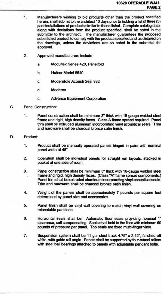
C. Panel Construction:
1. Panel construction shall be minimum 3" thick with 16-gauge welded steelframe and rigid, high density faces. Class A flame spread required. Paneltrim shall be extruded aluminum incorporating vinyl acoustical seals. Trimand hardware shall be charcoal bronze satin finish.
D. Product
1. Product shall be manually operated panels hinged in pairs with nominalpanel width of 48".
2. Operation shall be individual panels for straight run layouts, stacked inpocket at one side of room.
3. Panel construction shall be minimum 3" thick with 16-gauge welded steelframe and rigid, high density faces. (Class "A" flame spread components.)Panel trim shall be extruded aluminum incorporating vinyl acoustical seals.Trim and hardware shall be charcoal bronze satin finish.
4. Weight of the panels shall be approximately 7 pounds per square footdetermined by panel size and accessories.
5. Panel finish shall be vinyl wall covering to match vinyl wall covering onrelocatable partitions.
6. Horizontal seals shall be: Automatic floor seals providing nominal 1"clearance, self compensating. Seals shall hold to the floor with minimum 60pounds of pressure per panel. Top seals are fixed multi-finger vinyl.
7. Suspension system shall be 11 ga. steel track 4.75" x 2.12", finished offwhite, with guide rail angle. Panels shall be supported by four-wheel rollerswith steel ball bearings attached to panels with adjustable pendant bolts.
CA
RV
ER
RO
AD
CARVER HIGHALDINE ISD
ALDINE INDEPENDENT SCHOOL DISTRICT
ARCHITECTS
MOSELEY ASSOCIATES, INC.
HOUSTON, TEXAS
SUBMISSIONS & REVISIONS
L1.1
LANDSCAPE PLAN
Landscape Requirements:
1 Perform all work in accordance with all applicable laws, codes, and regulations required by authoritieshaving jurisdiction over such work and provide all inspections and permits required by Federal, State,and local authorities in supply, transportation, and installation of materials.
2. The contractor shall be responsible for the verification of all underground utility lines (telephone, gas,water, electrical, cable, TV, etc.) and all overhead utility easements prior to start of any planting works.
3. All plant materials shall possess the following minimum qualities:a. Plants shall be nursery grown in accordance with good horticultural practices under climatic
conditions similar to those of the project for at least twelve months.b. All plants shall be heavy, symmetrical, tightly knit, so trained or favored for development and
appearance as to be superior in form, number of branches, compactness, and symmetry.c. Plants shall be sound, healthy and vigorous, well branched, and densely foliated when in leaf.
They shall be free of disease, insects, pests, eggs, or larvae.d. All plants shall be true of species and variety and shall conform to measurements (caliper size,
trunk heights, spread) as specified on the drawings.e. Container grown stock when specified shall have grown in the container in which delivered for at
least six months, but not over two years. Samples must prove no rootbound conditions exist.f. Caliper measurements shall be taken at a point on the trunk six inches (6") above natural ground
line for trees up to four inches (4") in caliper.g. All trees shall be staked by a minimum of two metal "T" stakes for single trunk trees and three
stakes for all multi-trunk trees.
4. Planting mix shall be thoroughly mixed in the following proportions:a. Prepared soil as backfill for shade and ornamental trees shall be: 5 part clay loam topsoil + 2 part
compost + 1 part sharp sand + 4 Lbs. Commercial fertilizer per CY Or 10 Lbs. Organic fertilizer.b. Prepared soil as backfill for shrubs and groundcovers and seasonal colors shall be: 1 part
enriched mulch + 1 part compost bark mulch + 1 part enriched topsoil + 1 part No. 1 BankSand + 3 Lbs. Time- released fertilizer, 14-14-14 per CY or 8 Lbs. Organic fertilizer.
5. Excavation work and Surface drainage works shall conform to the following requirements:a. Test drainage of plant beds and plant pits by filling with water twice in succession. Conditions
permitting the retention of water for more than 24 hours shall be brought to the attention of theOwner.
b. Work shall include the final responsibility for proper surface drainage of planted areas. Anyobstructions on the site, or prior work done by another part, which precludes establishing properdrainage shall be brought to the attention of the Owner in writing.
c. Excavate each tree hole 18" deep plus the depth of the tree container size (15 gal. Or 30 gal. Or65 gal. Or 100 gal.).
d. Excavate entire shrub bed to a depth of 8" plus the depth of the shrub container size (5 gal.)unless noted as being pit planted on landscape legend.
e. Excavate entire groundcover bed to a depth of 6" plus the depth of the groundcover containersize (4" pot or 1 gal.).
6. Additional work requirements on landscape areas:a. Prior to installation of any planting works (trees, shrubs,groundcover and grass works); apply
"Round Up" in all planting areas to eradicate all weed growths on site.b. Install weed control barriers in all trees, shrub and groundcover planting areas. Weed barrier
fabric shall be black polypropylene sheet 27 mils thick, 4 oz/s.y. grab tensile strength per ASTMD-4632; 90 lbs. (machine direction) 50 lbs. (cross machine direction). Provide DeWitt "WeedBarrier" or aprpoved substitute.
c. Edge all planting bed areas with Ryerson steel edging to clearly define the edge of theplanting bed the start of the grass areas. Edging shall be Ryerson estate Curb, 1/8"x4" with newstakes free of rust.
d. Spread a minimum two inch layer of pine bark mulch overall shrub and groundcover bed areas.
7. Landscape maintenance work by the Landscape Contractor after final acceptance shall include thefollowing:a. The maintenance period shall commence upon inspection and approval at Final Acceptance and
shall be for a period of Thirty Days (30).b. The landscape contractor shall coordinate the watering program for all the landscape work with
the Owner.c. Maintenance of new plantings shall consist of watering, cultivating, weeding, mulching, restaking,
tightening and repair of guys; resetting plants for proper grades or upright position, and furnishingand application of pesticides/herbicides; sprays, and invigorants as are necessary to keepplantings free of insects and disease and in a thriving condition.
8. Warranty Periods, Plant Guarantees, and Replacements:a. Planting supplied shall be warranted to remain alive and healthy for a period of twelve months
(12) after the date of Final Acceptance by Owner. Plants in an impaired, dead, or dying conditionafter initial acceptance or within 12 months shall be removed and replaced immediately to thesatisfaction of the Owner.
Grass Hydromulching Work Requirements:
1. Grass works:a. Seed which has become wet, moldy and otherwise damaged in transit or in storage will not be
acceptable.b. All grass seed shall be fresh, re-cleaned grass seed of the latest crop, mixed in the following
proportions by weight and meeting the accepted standards of pure live seed content, purity andgermination.
c. Grass seed shall have the following minimum ratio:Summer Mix:Cynodon Dactylon (Hulled Common Bermuda Grass) 85% pure live seed at 75 Lbs. Pure liveseed per acre.Winter Mix:Cynodon Dactylon (Unhulled - Common Bermuda Grass) 85% pure live seed at 75 Lbs. Purelive seed per acre. Annual Rye Grass or equal, 85% pure live seed at 175 Lbs. Pure live seedper acre.
2. Slurry Mix Component per Acre shall be Wood cellulose fiber mulch = 2,000 pounds + Grass Seed asspecified + fertilizer (13-13-13) 800 pounds.
3. Hydromulched seeding on Prepared finished grades:a. Install and spread out a minimum of one inch layer of topsoil over all areas to be hydromulched.b. Bed preparation: Immediately after the finished grade has been approved, begin hydroseeding
operation to reduce excessive weed growth and erosion.c. Apply seed, fertilizer and mulch by spraying them on the previously prepared seedbeds in the
form of an aqueous mixture and by using the methods and equipment described herein.d. Particular care shall be exercised by the contractor to insure that the application is made uniformly
and at the prescribed rate and to guard against miss and overlapped areas.e. Where slope of areas to be grassed exceed a 3:1 H:V; an erosion control fabric shall be installed
prior to hyromulching process.4. Maintenance:
a. Maintenance shall consist of weeding, fertilizing, insect control, watering, replanting, mowing,maintaining of existing grades and repair of any erosion damages.
b. Guarantee growth and coverage of hydromulch planting shall be a minimum on ninety five percent95% of the area planted will be covered with specified planting after sixty days with no bare spotsvisible.
c. Watering: Coordinate with the Owner to properly operate irrigation system to assure a regular,deep watering program.
5. Inspection and Final Acceptance:Final acceptance of lawn establishment shall mean that hydroseed areas are Ninety Five percent95% uniform coverage of grass in excess of one inch height. No bare spots will be acceptable.
Owner's Responsibility For Maintenance
Landscape Contractor's Responsibilities:
Client acknowledges and agrees that proper Project maintenance is required after the Project is complete. A lack of or impropermaintenance in areas such as, but not limited to, operation and maintenance of automatic irrigation system, all site drainage and allplanting materials maintenance may result in damage to property or persons. Client further acknowledges that he is solely responsible forthe results of any lack of or improper maintenance.
All drainage (surface and subsurface) of all landscape areas within the project limits shall be the responsibility of the installing landscapecontractor and landscape maintenance company. All grading of areas along all building areas must absolutely have positive slope awayfrom building. In no case shall any plant bed be constructed along edge of building that will impede water flow away from building. Ifplanting beds are located at edges of building, landscape contractor shall make sure that these areas drain properly (surface andsubsurface-wise). Contractor shall install moisture barrier along building as necessary to keep water from penetrating underneath buildingslab.
"REFER TO FINISHED GRADES SHOWN ON PROJECT CIVIL GRADING PLAN. IT WILL REPRESENT FINAL ELEVATIONS. CARESHOULD BE TAKEN BY THE LANDSCAPE CONTRACTOR NOT TO INCREASE THESE FINISHED GRADES WITH LANDSCAPINGOR OTHER ALTERATIONS. THE THICKNESS OF SOD, GRASS AND LANDSCAPING MATERIALS SHOULD BE DEDUCTED FROMTHE FINISHED GRADE ELEVATIONS IN THESE CIVIL GRADING PLANS IN ORDER TO DETERMINE THE GROUND ELEVATIONSDURING CONSTRUCTION."
1L1.1
LANDSCAPE PLANSCALE: 1" = 20'-0"
RS T
R
EG I E
E
D
Wong &Associates, Inc.
5207 Spruce.Bellaire, Texas 77401-3310
Tel. 713 777 9198 Fax. 713 777 4404Member: American Society of Landscape Architects
PRIVATE DRIVE
CITY OF HOUSTONDEPARTMENT OF PLANNING & DEVELOPMENT
LANDSCAPE ANALYSIS FORMNon-Single Family Residential(Staff may create an artificial lot)
Length of property line in lineal feet as measured along each street separately.A. STREET TREES: Sec. 33-126 (a)
1. TREE AND SHRUB PLANTING REQUIREMENTS
Street name Lineal feet Tree Planting Requirements Equivalent Credits* Total Trees Planted
Carver Road 100.00 LF 4
Total Street Trees: 4
*Maximum street tree credits can not exceed 50% of each block face.
B. PARKING LOT TREES:50% of parking lot tress must be large trees.
Sec. 33-127 (a)
C. SHRUBS: Sec. 33-127 (b)
Each parking space must be within 120' of a tree.
52 52 5 n/a 5 5
Tree PlantingRequirements
EquivalentCredits
LargeTrees
SmallTrees
Total TreesPlanted
# ofSpaces
n/a
D. LANDSCAPE BUFFER:(Min. 6') Sec. 33-128 (2) Evergreen screening.
Shrubs Requirements:
Street Tree Planting Requirements Requirements Total shrub Requirements
4 4x10 40
Sec. 33-128 (1) Wood, concrete masonry opaque screening fence.
CREDITS WORKSHEET
ParkingStreet
3. Preservation of on-site trees, per the following schedule in caliper:Minimum 4" to 6" 2 TreesGreater than 6" but less than 12"12" and greaterTotal number of tree credits for this option.______________________________ trees.
3 Trees4 Trees
4. Credit for preserving existing right of way street trees. n/a
n/a
n/a
4
4
Sec. 33-123 (a) Tree Planting Equivalency Credits
Total Number of ProposedParking Spaces
Shrubs Provided
46
75% of the shrubs must be planted along the perimeter of the parking lot.(Shrubs are required for new or the expanded portion of parking lots)
A 6' high wood, concrete masonry opaque screening fence, or 15' wide evergreen planting strip along thetotal length of property line adjacent to existing single family residential, or limit of expansion adjacent toexisting single family residential. (Site plan must show land use on all sides of the property).
n/an/an/a
n/an/a
n/an/a
n/an/a
2. Depositing of monies with parks and Recreation Departments. $ 155.00 per tree. Proposedcredits cannot exceed 30% of tree Planting requirements above. Amount to be deposited:Proposed Credits___________________ x $155.00=$_______________ (The combinedcredits under items 1 & 2 may no exceed 50% of total tree planting requirements.)
1. Number of proposed trees exceeding 4" in caliper (not applicable). Each 4" trees is two (2)credit.
5. Proposed total number of tree credits. (to receive credits, documentations must be providedin conformance to section 33-122).
Tree Planting Requirements for Parking Lots.
LO
KR
9
Symbol Quantities(Verify)
BotanicalName
CommonName
Size and Plant Requirements
QuercusVirginianaRosaRadrazz
Live Oak
KnockoutRoses
2" cal. min. 30 gal. container.
3 gal. planted at 30" o.c. double row.
Landscape Legend:
46

CIVIL ADDENDUM NO. 1
CLARIFICATION:
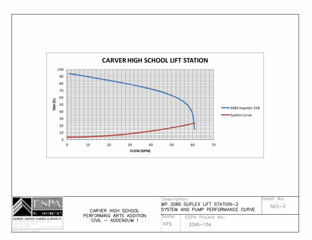
The following items provide specifications and details for the proposed sanitary sewer lift station (See Sht C‐7).
SPECIFICATION:
Section 11307 – Duplex Grinder Pump Lift Station.
DRAWINGS:
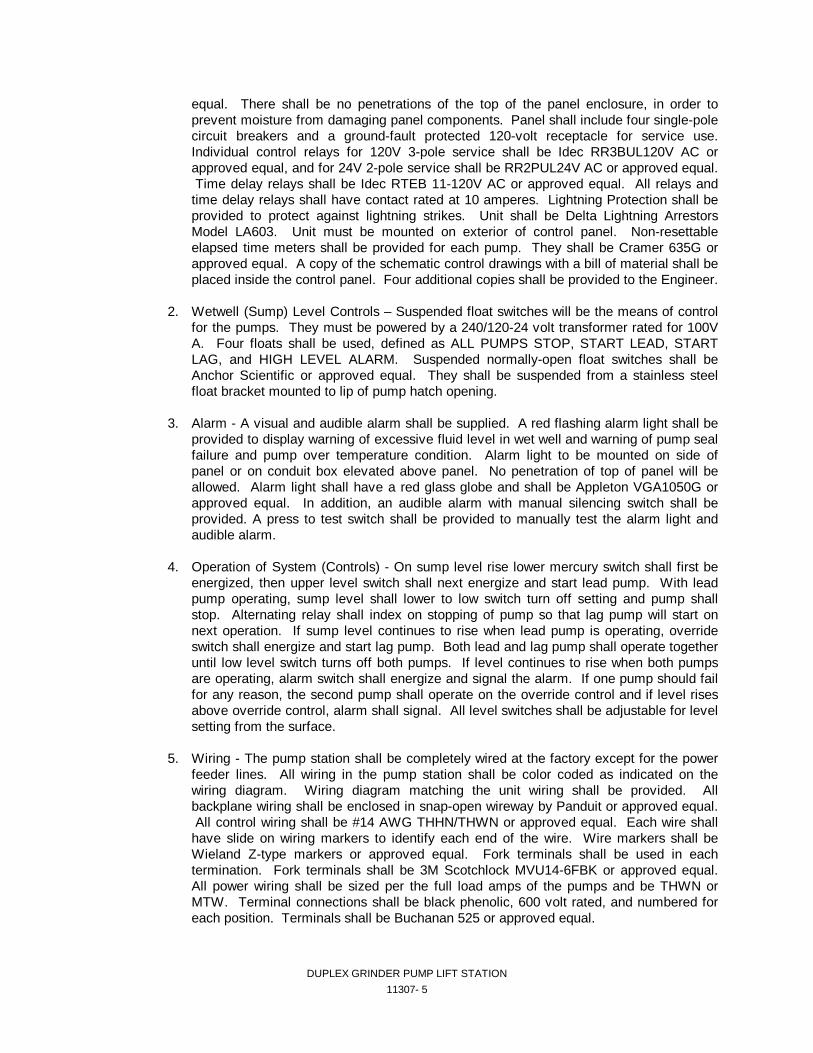
SKC‐1 – MP 3085 Duplex Lift Station – 1 (Section View)
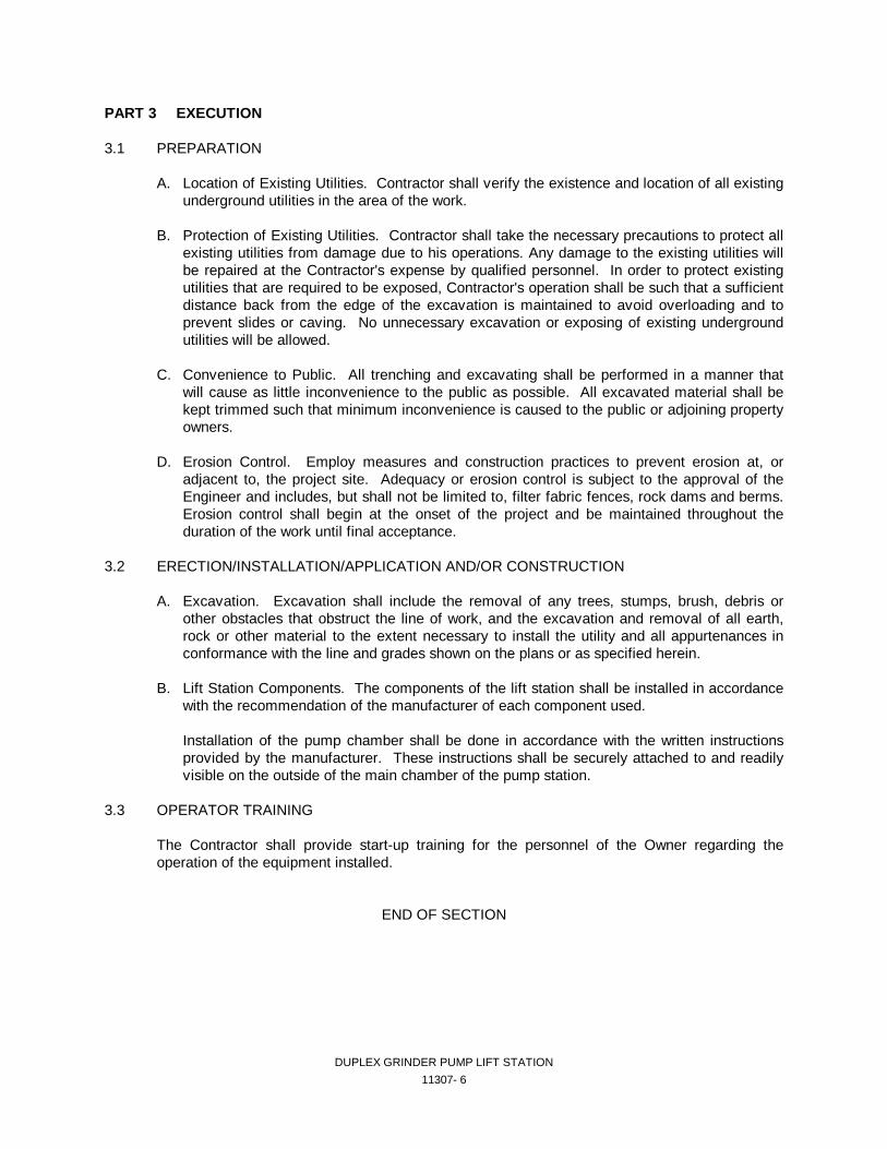
SKC‐2 – MP 3085 Duplex Lift Station – 2 (Top View and Base Section)
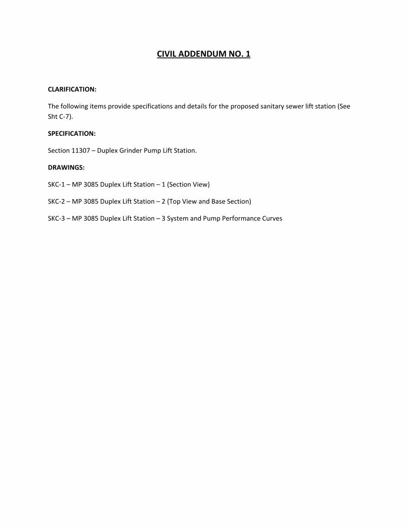
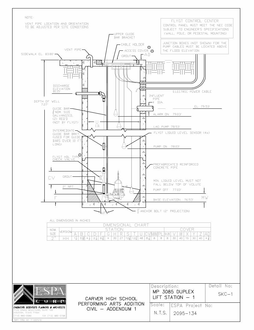
SKC‐3 – MP 3085 Duplex Lift Station – 3 System and Pump Performance Curves
DUPLEX GRINDER PUMP LIFT STATION
11307- 1
DUPLEX GRINDER PUMP LIFT STATION
SECTION 11307
PART 1 GENERAL 1.1 SUMMARY
This section describes the requirements for a duplex (two pump) submersible grinder pump lift station.
1.2 RELATED SECTIONS
Section 02210 - Excavating, Grading and Fill Electrical Sections
1.3 MEASUREMENT AND PAYMENT
Measurement and payment will be on a lump sum basis. The payment made according to the Bidder's proposal shall be full compensation for all materials, tools, equipment, labor, superintendence, fees, permits, and incidentals for a complete operational facility.
1.4 SYSTEM DESCRIPTION
The lift station includes the wet well basin, pumps, discharge piping to a point up to and including the 45° fitting connecting the H.D.G. steel piping with the ASTM D-2241 SDR 21 PVC force main, electrical service entrance, electrical starting equipment, electrical controls including alarm, site grading, and incidentals for a complete operational facility.
1.5 SUBMITTALS
A. Shop Drawings and Pump Performance Curves
Contractor shall submit to Engineer for approval six (6) copies of data on equipment proposed to be used, including pump performance curves. Performance curves shall include efficiency curves and horsepower requirements.
B. Operation and Maintenance Manuals
The Contractor shall furnish the Owner with five (5) copies of operation and maintenance instructions for the equipment furnished under this specification.
1.6 QUALITY ASSURANCE
A. Testing and Materials Only materials specified and approved shall be used in construction of the facility. All
components of the pump station shall be given an operations test of all equipment at the factory to check for excessive vibration, for leaks in all piping or seals, and for correct operation of the control system and all auxiliary equipment.
DUPLEX GRINDER PUMP LIFT STATION
11307- 2
The pump suction and discharge lines shall be coupled to a reservoir and the pump shall recirculate water under simulated service connections.
B. Pump Warranty The pump shall be guaranteed to be free from defects in materials and workmanship for a
period of one year from the date of acceptance. 1.7 DELIVERY, STORAGE, AND HANDLING All equipment incorporated into construction of the facility shall be delivered, stored, and handled
in accordance with the recommendation of the manufacturer for each piece of equipment. 1.8 PROJECT SITE CONDITIONS The Contractor shall visit the site to become familiar with the site conditions. Contractor is
responsible for performing any testing he deems necessary to satisfy himself of site conditions. PART 2 PRODUCTS 2.1 MANUFACTURERS The lift station pumps shall be manufactured by Flygt or preapproved equal. 2.2 MATERIALS AND/OR EQUIPMENT A. Wet well - Reinforced concrete pipe meeting ASTM C478, rubber gasket joints, with inside
diameter and depth as shown on the plans. The interior shall be coated with a 10 mil thickness of coal tar epoxy, Pittsburgh two (2) part "Coal Cat", component "A" is No. 97-640 and component "B" is No. 97-641; Tnemec two (2) part "Tneme-Tar", No. 46-413; or approved equal.
B. Pumps and Motor - Two submersible grinder pumps shall be installed in the wet well.. Each
pump shall have a capacity of 60.6 GPM at 24.5 TDH.. Pump motors shall be of the phase, voltage, and minimum horsepower shown on the plans. The actual horsepower of the pump used may be more than that shown on the plans depending on the manufacturer of the actual pump used.
The pump(s) shall be capable of handling domestic sewage. The 2” discharge connection
elbow shall be permanently installed in the wet well or basin along with the discharge piping. The pump(s) shall be automatically connected to the discharge connection elbow when lowered into place, and shall be easily removed for inspection or service. There shall be no need for personnel to enter pump well/basin for pump inspection. Sealing of the pumping unit to the discharge connection elbow shall be accomplished by a simple linear downward motion of the pump. A sliding guide bracket shall be an integral part of the pump unit. The entire weight of the pumping unit shall be guided by no less than two stainless steel guide rails and pressed tightly against the discharge connection elbow with metal-to-metal contact. Sealing of the discharge interface by means of a diaphragm, O-ring or other devices will not be acceptable. No portion of the pump shall bear directly on the floor of the sump. The pump, with its appurtenances and cable, shall be capable of continuous submergence underwater without loss of watertight integrity to a depth of 65 feet.
DUPLEX GRINDER PUMP LIFT STATION
11307- 3
Major pump components shall be of gray cast iron, Class 30, with smooth surfaces devoid of blow holes and other irregularities. Where watertight sealing is required, O-rings made of nitrile rubber shall be used. All exposed nuts and bolts shall be of AISI type 304 stainless steel or brass construction. All surfaces, coming into contact with sewage, other than stainless steel or brass, shall be protected by an approved sewage resistant coating (choleric rubber paint finish). Impeller shall be sprayed with PVC epoxy primer.
All mating surfaces where watertight sealing is required shall be machined and fitted with
nitrile rubber O-rings. Fitting shall be such that sealing is accomplished by metal to metal contract between machined surfaces. This will result in controlled compression of nitrile rubber O-rings without the requirement of a specific torque limit. No secondary sealing compounds, rectangular gaskets, elliptical O-rings, grease or other devices shall be used.
The cable entry shall be an integral part of the stator casing. The cable entry shall be
comprised of a single cylindrical elastomer grommet flanked by stainless steel washers and a ferrule designed with close tolerance fit against the cable outside diameter and the entry inside diameter. This will provide a leak-proof, torque free seal at the cable entrance. Epoxies, silicones or other secondary sealing systems shall not be considered acceptable.
The pump motor shall be squirrel cage, induction, shell type design, housed in an air-filled,
watertight chamber. The stator winding and stator leads shall be insulated with moisture resistant Class F insulation which will resist a temperature of 155 degrees C (311 degrees F). The stator shall be dipped and baked three times in Class F varnish and shall be heat-shrink fitted into the stator housing. The use of bolts, pins or other fastening devices requiring penetration of the stator housing shall be rejected. The rotor bars and short circuit rings shall be aluminum. At the design point, the temperature in the windings shall not exceed 311 degrees F.
At the maximum rated power of this unit, thermal radiators (cooling fins) integral to the stator
housing, shall be adequate to provide the cooling required by the motor. A minimum of two thermal sensors shall be imbedded in the stator winding end coils. These sensors shall be wired to the control panel for use in conjunction with the external motor overload protection.
The pump shaft shall be of AISI type 240 stainless steel. Each pump shall be provided with a tandem mechanical shaft seal system. The upper of the
tandem set of seals shall operate in an oil chamber located just below the stator housing. This set shall contain one stationary carbon ring and one positively-driven rotating ceramic ring and function as an independent barrier between the pumped liquid and the stator housing. The lower of the tandem set of seals functions as the primary barrier between the pumped liquid and the stator housing. This set shall consist of a stationary ring and a positively driven rotating ring both of which shall be ceramic.
Each interface shall be held in contact by its own spring system. The seals shall require
neither maintenance nor adjustment, but shall be easily inspected and replaceable. The following seal types shall not be considered acceptable nor equal to the dual independent seal specified. Shaft seals without positively driven rotating members, or conventional double mechanical seals containing either a common single or double spring acting between the upper and lower units.
Manufacturers requiring moisture detection devices for warranty shall supply a lockout
device with a manual reset in the control panel.
DUPLEX GRINDER PUMP LIFT STATION
11307- 4
The pump shaft shall rotate on two (2) permanently lubricated bearings. The upper bearing shall be a single row ball bearing and the lower bearing a two row angular contact ball bearing.
The impeller shall be of the multi-vane, semi-open type of Cast Iron ASTM A 48-76 class
30B, and shall be fastened to the pump-motor shaft by a tapered collet and locking screw. The cutting components shall consist of a rotating cutter of chrome alloyed cast iron and a
stationary cutter of hardened stainless steel. C. Pump Guide Rails, Lifting Cables and Pump Bails, Fasteners, and All Hardware Inside
Wetwell - stainless steel. D. Discharge Piping and Valves - A check valve and gate valve shall be installed on the
discharge pipe from each of the pumps. E. Electrical Service Entrance - An electrical service entrance is required for electrical power to
the lift station. F. Electrical Starting Equipment, Breakers, Controls, and Wiring 1. Control Panel - Control panel shall have a NEMA 4X fiberglass enclosure with a stainless
steel hinged deadfront door on a continuous piano hinge and removable sub-panel. The inner door shall be stainless steel or aluminum mounted on a continuous hinge and shall be furnished for protection against exposed wiring. Inner door shall be equipped with cutouts for access to the circuit breakers. A lock hasp shall be provided on door. A circuit breaker shall be provided for each pump with mechanical through-the-door operators mounted on the inner door and shall be Square D Mag-Guard or preapproved equal. A magnetic starter with three (3) leg overload protection for three-phase operation or one (1) leg overload protection for single-phase operation shall be supplied for each pump. The control circuit shall be protected by a single-pole 10 Ampere circuit breaker. An alternating relay shall be provided to alternate pumps on each successive cycle of operation. Starters shall have auxiliary contacts to operate both pumps on override condition. An interlock relay shall be provided to automatically reconnect the control circuit in case of circuit breaker trip on one (1) pump. H-O-A switches and run lights shall be supplied for each pump. Pump control switches and pilot devices will be oil-tight units mounted on inner door. Toggle switches will not be acceptable. Hand-off-auto switches shall be Square D 9001 K Series or approved equal. Pilot lights shall be Idec APD series or approved equal. LED pilot lights are not acceptable. Detection and display of seal failure and overtemperature failure within each pump shall be required, and the malfunction condition shall activate an alarm light for each pump in the inner door of the control panel and shall also activate the exterior red flashing light and audible horn alarm. The overtemperature and seal failure alarm circuit shall be self-latching and shall require resetting by means of a pushbutton on the inner door. The overtemperature alarm shall lock out each individual pump. Alternator relay shall be Diversified ARB-120-AEA or equal, with switch to allow choice of either pump as lead pump or automatic alternation. Motor starters must be NEMA-rated for horsepower. No size 00 starters and no IEC-rated starters will be allowed in the panel. Starter coils shall be 120-volt. Starters will be Square D 8536 or approved equal. All starters, breakers, and relays must be enclosed. Open-frame components shall not be used. IEC rated components are not acceptable. A power monitor relay shall be used to protect the pumps against damage from being directly switched by the power monitor relay. Activation time of the relay shall be adjustable, but not be longer than 250 milliseconds with an adjustable release time of up to 30 seconds. Relay shall be PBD series by Diversified or approved
DUPLEX GRINDER PUMP LIFT STATION
11307- 5
equal. There shall be no penetrations of the top of the panel enclosure, in order to prevent moisture from damaging panel components. Panel shall include four single-pole circuit breakers and a ground-fault protected 120-volt receptacle for service use. Individual control relays for 120V 3-pole service shall be Idec RR3BUL120V AC or approved equal, and for 24V 2-pole service shall be RR2PUL24V AC or approved equal. Time delay relays shall be Idec RTEB 11-120V AC or approved equal. All relays and time delay relays shall have contact rated at 10 amperes. Lightning Protection shall be provided to protect against lightning strikes. Unit shall be Delta Lightning Arrestors Model LA603. Unit must be mounted on exterior of control panel. Non-resettable elapsed time meters shall be provided for each pump. They shall be Cramer 635G or approved equal. A copy of the schematic control drawings with a bill of material shall be placed inside the control panel. Four additional copies shall be provided to the Engineer.
2. Wetwell (Sump) Level Controls – Suspended float switches will be the means of control
for the pumps. They must be powered by a 240/120-24 volt transformer rated for 100V A. Four floats shall be used, defined as ALL PUMPS STOP, START LEAD, START LAG, and HIGH LEVEL ALARM. Suspended normally-open float switches shall be Anchor Scientific or approved equal. They shall be suspended from a stainless steel float bracket mounted to lip of pump hatch opening.
3. Alarm - A visual and audible alarm shall be supplied. A red flashing alarm light shall be
provided to display warning of excessive fluid level in wet well and warning of pump seal failure and pump over temperature condition. Alarm light to be mounted on side of panel or on conduit box elevated above panel. No penetration of top of panel will be allowed. Alarm light shall have a red glass globe and shall be Appleton VGA1050G or approved equal. In addition, an audible alarm with manual silencing switch shall be provided. A press to test switch shall be provided to manually test the alarm light and audible alarm.
4. Operation of System (Controls) - On sump level rise lower mercury switch shall first be
energized, then upper level switch shall next energize and start lead pump. With lead pump operating, sump level shall lower to low switch turn off setting and pump shall stop. Alternating relay shall index on stopping of pump so that lag pump will start on next operation. If sump level continues to rise when lead pump is operating, override switch shall energize and start lag pump. Both lead and lag pump shall operate together until low level switch turns off both pumps. If level continues to rise when both pumps are operating, alarm switch shall energize and signal the alarm. If one pump should fail for any reason, the second pump shall operate on the override control and if level rises above override control, alarm shall signal. All level switches shall be adjustable for level setting from the surface.
5. Wiring - The pump station shall be completely wired at the factory except for the power
feeder lines. All wiring in the pump station shall be color coded as indicated on the wiring diagram. Wiring diagram matching the unit wiring shall be provided. All backplane wiring shall be enclosed in snap-open wireway by Panduit or approved equal. All control wiring shall be #14 AWG THHN/THWN or approved equal. Each wire shall have slide on wiring markers to identify each end of the wire. Wire markers shall be Wieland Z-type markers or approved equal. Fork terminals shall be used in each termination. Fork terminals shall be 3M Scotchlock MVU14-6FBK or approved equal. All power wiring shall be sized per the full load amps of the pumps and be THWN or MTW. Terminal connections shall be black phenolic, 600 volt rated, and numbered for each position. Terminals shall be Buchanan 525 or approved equal.
DUPLEX GRINDER PUMP LIFT STATION
11307- 6
PART 3 EXECUTION 3.1 PREPARATION A. Location of Existing Utilities. Contractor shall verify the existence and location of all existing
underground utilities in the area of the work. B. Protection of Existing Utilities. Contractor shall take the necessary precautions to protect all
existing utilities from damage due to his operations. Any damage to the existing utilities will be repaired at the Contractor's expense by qualified personnel. In order to protect existing utilities that are required to be exposed, Contractor's operation shall be such that a sufficient distance back from the edge of the excavation is maintained to avoid overloading and to prevent slides or caving. No unnecessary excavation or exposing of existing underground utilities will be allowed.
C. Convenience to Public. All trenching and excavating shall be performed in a manner that
will cause as little inconvenience to the public as possible. All excavated material shall be kept trimmed such that minimum inconvenience is caused to the public or adjoining property owners.
D. Erosion Control. Employ measures and construction practices to prevent erosion at, or
adjacent to, the project site. Adequacy or erosion control is subject to the approval of the Engineer and includes, but shall not be limited to, filter fabric fences, rock dams and berms. Erosion control shall begin at the onset of the project and be maintained throughout the duration of the work until final acceptance.
3.2 ERECTION/INSTALLATION/APPLICATION AND/OR CONSTRUCTION A. Excavation. Excavation shall include the removal of any trees, stumps, brush, debris or
other obstacles that obstruct the line of work, and the excavation and removal of all earth, rock or other material to the extent necessary to install the utility and all appurtenances in conformance with the line and grades shown on the plans or as specified herein.
B. Lift Station Components. The components of the lift station shall be installed in accordance
with the recommendation of the manufacturer of each component used. Installation of the pump chamber shall be done in accordance with the written instructions
provided by the manufacturer. These instructions shall be securely attached to and readily visible on the outside of the main chamber of the pump station.
3.3 OPERATOR TRAINING The Contractor shall provide start-up training for the personnel of the Owner regarding the
operation of the equipment installed. END OF SECTION
0
10
20
30
40
50
60
70
80
90
100
0 10 20 30 40 50 60 70
TDH (ft)
FLOW (GPM)
CARVER HIGH SCHOOL LIFT STATION
3085 Impeller‐258
System Curve
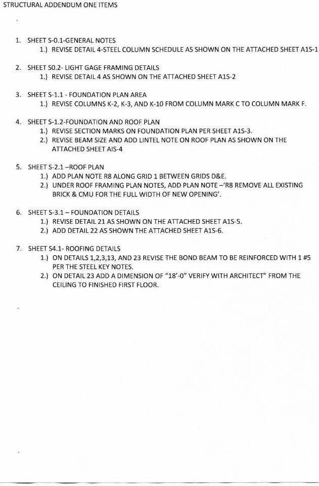
STRUCTURAL ADDENDUM ONE ITEMS
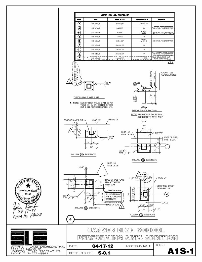
1. SHEET S-O.l-GENERAL NOTES
1.) REVISE DETAIL 4-STEEL COLUMN SCHEDULE AS SHOWN ON THE ATTACHED SHEET A1S-1
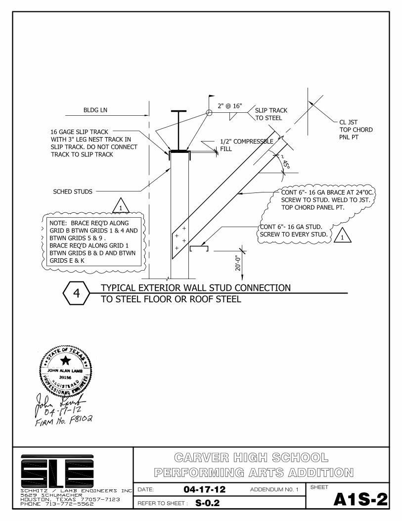
2. SHEET S0.2- LIGHT GAGE FRAMING DETAILS
1.) REVISE DETAIL 4 AS SHOWN ON THE ATTACHED SHEET A1S-2
3. SHEET S-l.l- FOUNDATION PLAN AREA
1.) REVISE COLUMNS K-2, K-3, AND K-10 FROM COLUMN MARK C TO COLUMN MARK F.
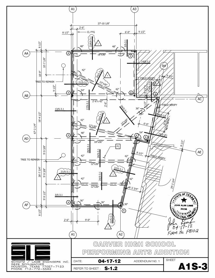
4. SHEET S-1.2-FOUNDATION AND ROOF PLAN
1.) REVISE SECTION MARKS ON FOUNDATION PLAN PER SHEET A1S-3.
2.) REVISE BEAM SIZE AND ADD LINTEL NOTE ON ROOF PLAN AS SHOWN ON THE
ATTACHED SHEET AIS-4
5. SHEET S-2.1-ROOF PLAN
1.) ADD PLAN NOTE R8 ALONG GRID 1 BETWEEN GRIDS D&E.
2.) UNDER ROOF FRAMING PLAN NOTES, ADD PLAN NOTE -'R8 REMOVE ALL EXISTING
BRICK & CMU FOR THE FULL WIDTH OF NEW OPENING'.
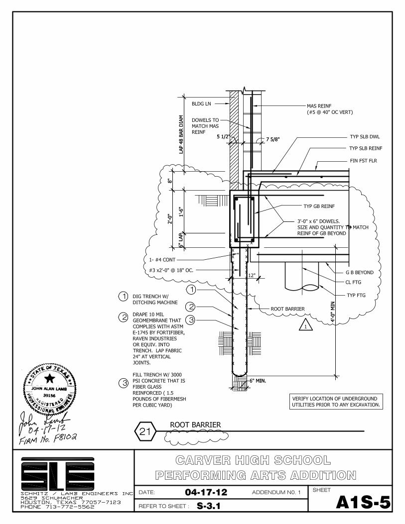
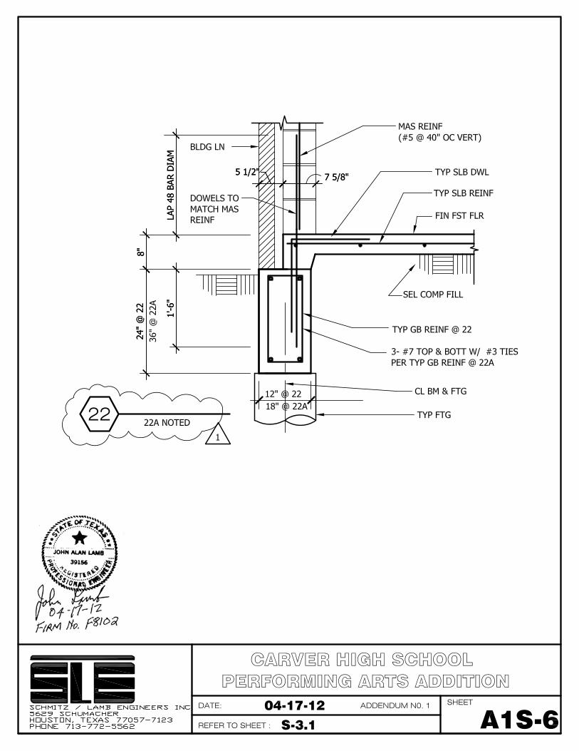
6. SHEET S-3.1 - FOUNDATION DETAILS
1.) REVISE DETAIL 21 AS SHOWN ON THE ATTACHED SHEET A1S-5.
2.) ADD DETAIL 22 AS SHOWN THE ATTACHED SHEET A1S-6.
7. SHEET S4.1- ROOFING DETAILS
1.) ON DETAILS 1,2,3,13, AND 23 REVISE THE BOND BEAM TO BE REINFORCED WITH 1 #5
PER THE STEEL KEY NOTES.
2.) ON DETAIL 23 ADD A DIMENSION OF "18'-0" VERIFY WITH ARCHITECT" FROM THE
CEILING TO FINISHED FIRST FLOOR.