cartridge replacement manual - free instruction · pdf fileplease refer to this guide if you...
TRANSCRIPT

CARTRIDGE REPLACEMENTMANUALAquavalve Series:
200/400600/430
700/Shiraz605/405609/409
Opto ThermoQuartz Thermo
Axis ThermoAquatique
Colt Dream
Hydramax
Aquamixa Series:300/310

CONTENTS
General Notes – All Models 2
Product Identification 3
Components 5
Cartridge Information 6
Important Information – 022802 Cartridge 7
Aquavalve Series 200/400 8
Aquavalve Series 600/430 11
Aquavalve Series 605/405 15
Aquavalve Series 609/409 & Colt 18
Aquavalve Series 700/Shiraz & Aquatique 22
Aquamixa Series 300/310 26
Axis Thermo, Quartz Thermo & Dream 30
Opto Thermo & Hydramax 32
Temperature Limit Stops 34
1

GENERAL NOTES – all modelsPlease refer to this guide if you are unsure of your shower type
2
2. Cartridge replacement is generally straightforward, however the operation may involve the removal of some small components and therefore it is strongly recommended that after draining down, the waste outlet be covered to prevent loss of any parts.
3 Before commencing cartridge replacement, please ensure that you familiarise yourself with the location of all relevant isolation valves and that they are operational. 4 Systems, which incorporate a pump, must be electrically isolated and the controlling fuse removed before commencement.
5 Before fitting the replacement cartridge, it is recommended that the ‘Base’ or ‘Hot Water’ O-ring is also replaced. Certain products require the O-ring to be fitted into the waterway inside the body; others require the O-ring to be fitted onto the T Tube on the rear of the cartridge. A new O-ring is supplied with the cartridge.
6 Filters (See Fig 1 Components): To maximise product life, your new cartridge is protected by a two-part filter system. The hot water element is a push fit insert situated at the base of the cartridge centre tube and cold filtration is achieved by a captive mesh in the cartridge gasket. It is of course imperative that this new gasket is fitted with the replacement cartridge. Should flow rate problems develop at some future time, it is suggested that the first course of action is to check the condition of these items.
7 Pressures: All Aqualisa cartridges are designed to control static pressures up to 10 bar (145psi). Where pressures are likely to be excessive, a pressure reducing valve (PRV) must be fitted into the incoming mains supply. A setting of 4 bar (60psi) is recommended. It should be noted that daytime pressures approaching 6 bar (80psi) can rise above the stated maximum during periods of low demand – typically overnight.
Should you experience any difficulties, our Customer Services helpline is open from 8.30am to 5.00pm Monday to Friday to answer any questions or guide you through any aspect of fitting this part. Customer helpline: 01959 560010 Email: [email protected]
We advise that when replacing your cartridge, that you change the cartridge like for like. Please refer to page 6 for cartridge information and page 7 for specific flow regulator information relating to combination boilers.
1

PRODUCT IDENTIFICATIONPlease refer to this guide if you are unsure of your shower type
3
200/400 Concealed 600 Concealed
605 609/409/Colt
700 MK2 Concealed 700 MK2 Exposed

4
Aquatique Concealed Aquatique Exposed
Axis Thermo Quartz Thermo
Dream Opto Thermo
300 MK 2 Aquamixa
If you require further help or advice, please contact Aqualisa
Customer Service on 01959 560010.
Hydramax
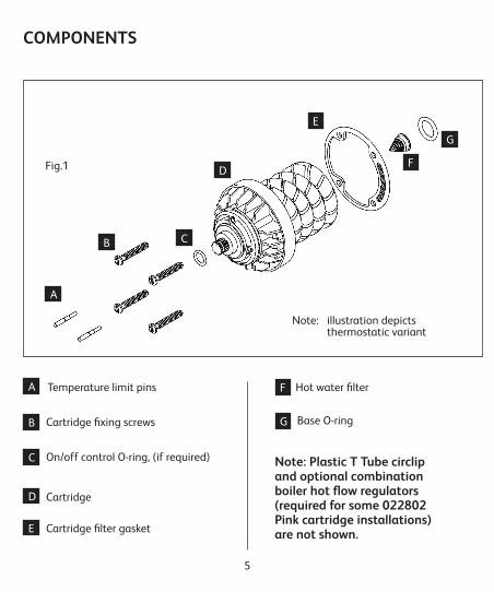
COMPONENTS
5
Temperature limit pins Hot water filter
Cartridge fixing screws
On/off control O-ring, (if required)
Cartridge
Cartridge filter gasket
Note: illustration depicts thermostatic variant
A
B C
D
E
F
G
A
B
C
D
E
F
G
Fig.1
Note: Plastic T Tube circlip and optional combination boiler hot flow regulators (required for some 022802 Pink cartridge installations) are not shown.
Base O-ring

CARTRIDGE INFORMATION
6
Cartridge Number 022801 Thermostatic – Identified by a GREY ring on cartridge face. Control of gravity, gravity pumped and balanced high-pressure systems, may also be used for unbalanced (combination boiler) systems when flow regulator is fitted into the cold inlet.
Cartridge Number 022802 Thermostatic – Identified by a PINK ring on cartridge face. Control of unbalanced systems such as combination boiler and multi-point water heaters. Please note: There is a coloured flow regulator that sits in the bottom of the T Tube (hot side); where applicable this flow regulator should be used with the new cartridge. Please refer to page 7 for specific flow regulator information relating to combination boilers.
Cartridge Number 022803 Thermostatic – Identified by a GREEN ring on cartridge face. Control of balanced high pressure systems (unvented storage etc). Please note: This cartridge is primarily used on currentOpto Thermo high pressure concealed and Hydramax high pressure valves. Usage of this cartridge on Aquavalves ceased mid 1993, for replacement units, use 022801 GREY thermostatic cartridges.
Cartridge Number 022804 Manual (Non thermostatic) – Identified by a BLUE ring on cartridge face. May be used on all applications except combination boiler and multipoint boilers.
Cartridge Number 022805 Manual (Non thermostatic) – Identified by a WHITE ring on cartridge face. Due to the reduced length, this cartridge was fitted only in ‘430’ range products manufactured between 1993 and 1996.
Cartridge Number 022809 Thermostatic – Identified by an ORANGE ring on cartridge face. Control of gravity and gravity pumped systems. This cartridge is used on Opto Thermo gravity systems.
Fig.2

IMPORTANT INFORMATION REGARDING 022802 PINK CARTRIDGES
For optimum performance, replacement pink cartridges, part number 022802 for use with showers fitted to combination boiler water systems, are now supplied complete with a flow regulator fitted into the hot inlet port at the end of the T Tube of the cartridge.
The replacement pink cartridge is factory fitted with a YELLOW flow regulator suitable for use with a 24kW (80000Btu) combination boiler. If the shower is fitted where there is a 30kW (100000Btu) boiler in operation, the factory fitted regulator should be replaced with the OLIVE regulator. Similarly, if the shower is fitted where there is a 35kW+ (120000+Btu) boiler in operation, the factory fitted regulator should be replaced with the BLUE regulator.
If in any doubt as to your boiler rating, please contact the appliance manufacturer prior to the installation of the replacement cartridge commencing.
Changing the flow regulator
If the factory fitted YELLOW regulator is compatible with your boiler, please follow the instructions for your particular shower as detailed within this cartridge replacement manual. However, if it isnecessary to change the regulator to suit your relevant boiler, please follow the instructions opposite.
Remove the flow regulator housing from the rear of the cartridge T Tube, using a small flat bladed screw driver if necessary.
Fit the suitable replacement OLIVE or BLUE flow regulator assembly, as detailed opposite, into the cartridge T Tube ensuring that the O-ring faces into the incoming flow of water.
1
2
Fig.A
Fig.B
Once the relevant regulator has been installed, fit the replacement cartridge in accordance with the instructions for your particular shower as detailed within this cartridge replacement manual.
7

200/400 ‘Classic’ Series (1979 - 1990)
8
Introduction
The ‘200’ thermostatic series and the ‘400’ manual series valves may be installed ‘built in’ or ‘exposed’. The sequence of servicing is the same for all variants. Please refer to the cartridge guide on page 6 if required.
You will need:
• No. 2 Posidriv screwdriver
• Pliers
• Crochet hook or similar sharp pointed tool
• Torch
• Silicone lubricant or petroleum jelly (Vaseline, etc)
Removing the cartridge (Fig 2)
1. Locate your shower isolating valves and turn fully off.2. Turn the shower on and allow all residual water to drain away.3. Cover the waste outlet of your bath or tray to prevent loss of any screws etc.4. Pull the On/off control free.5. Remove the four screws, which secure the temperature control lever in position and remove the lever.
6. If fitted, remove the two brass temperature limit rings from the cartridge face. 7. Remove the four screws, which secure the cartridge in position – the cartridge can now be pulled clear of the body using pliers on the On/off shaft if necessary.
Note:Before fitting the replacement cartridge, it is recommended that the ‘Base’ or ‘Hot Water’ O-ring which is situated in the waterway inside the body is also replaced. A new O-ring is supplied with your cartridge. Please proceed as follows:
8. Carefully remove the existing O-ring using a suitable tool i.e. crochet hook or similar, take care to avoid any damage to the seating (Fig 3).9. The new O-ring may be fitted into position by first sliding it onto the blade of a screwdriver. Hold the tip of the screwdriver into the hot water way and then manoeuvre the O-ring down into position (Fig 4).
O-ring
HookFig.3
200/400 Concealed 200/400 Exposed

9
10. Work the O-ring into the seating, use a torch if necessary to check for correct location.
11. Apply a smear of silicone lubricant or petroleum jelly to the face of the O-ring.
FITTING THE NEW CARTRIDGE
The plated fixing screws, which are included with your new cartridge, must only be used on later pattern bodies which do not contain brass fixing inserts.
DO NOT ATTEMPT TO USE THESE SCREWS IF BRASS M5 POSIDRIV SCREWS SECURE YOUR CARTRIDGE.
These original screws must be used to secure your new cartridge.
Fig.4
Fig.5
Fig.6
Gasket & screws in position
Cold water way
Fig.7
Temperature limiting holes

10
12. Push the four cartridge fixing screws through the face of the cartridge and attach the gasket to the screws, ensuring that it is correctly positioned (Fig 5).
Note: If changing a PINK 022802 cartridge, on removal of the old cartridge, if there is a coloured flow regulator fitted into the bottom of the T Tube, the replacement cartridge will also require the flow regulator to be fitted, like for like. Please refer to page 7 for information regarding the fitment of the flow regulator.
13. Offer the cartridge up to the body after checking that the waterway in the rear of the cartridge is in alignment with the waterway, which is situated in the face of the body (Fig 6).
14. Tighten the four fixing screws sufficiently to achieve a watertight seal.
15. Loosely attach the On/off control to the front of the cartridge and turn clockwise to ensure that the shower is fully off, remove the control.
16. Turn on the supplies and check for leaks.
17. Set the shower to the mid-blend position by turning the coloured ring until the semi circle of small holes radiate down from twelve o’clock to six o’clock. This operation will be made easier, if a temperature lever fixing screw is first inserted by two or three turns into one of the fixing points (Fig 7).
Should you wish to restrict the amount of travel of the temperature control lever to a comfort or safety zone, please refer at this point to ‘Temperature Limit Pins’ on page 34. If this facility is not required then please proceed as follows:
18. With the lever in the vertical position, refit the temperature control using the four M4 Posidriv screws provided. A little more than hand tight will be sufficient, excessive force will result in very stiff operation of the control (Fig 8).19. Locate the small O-ring into the peripheral groove on the On/off shaft and apply a slight smear of silicone lubricant or petroleum jelly.20. Push the On/off control fully home (Fig 8).
Fig.8

600 Series Thermostatic Aquavalve (1990 – 1996)400 Series Mark 2 Aquavalve (1990 – 1993)430 Series ‘Short Bodied’ Manual Aquavalve (1993 – 1996)
11
Introduction:The ‘600’ or thermostatic series and the ‘400’ series mark 2 manual valves may be installed ‘built in’ or fully exposed. The sequence of servicing is the same for all variants with the exception of the ‘430’ models which did not include loose temperature markings. Please refer to the cartridge guide on page 6 if required.
You Will Need:• No.2 Posidriv screwdriver• T25 Torx screwdriver or 8mm flat blade • screwdriver• Pliers• Crochet hook or similar sharp pointed tool• Torch• Silicone lubricant or petroleum jelly (Vaseline, etc)
Removing the cartridge (Fig 9)1. Locate your shower isolating valves and turn fully off.2. Turn the shower on and allow all residual water to drain away.3. Cover the waste outlet of your bath or tray to prevent loss of any screws etc.4. Pull the On/off control free.
5. Remove the four screws, which secure the temperature control lever in position. Remove the lever and coloured temperature ellipses.
6. If fitted, remove the two brass temperature limit rings from the cartridge face.
7. Remove the four screws, which secure the cartridge in position – the cartridge can now be pulled clear of the body using pliers on the On/off shaft if necessary.
Fig.9
600430
600 Exposed600 Concealed 430 Concealed

12
Note:
Before fitting the replacement cartridge, it is recommended that the ‘Base’ or ‘Hot Water’ O-ring which is situated in the waterway inside the body is also replaced. A new O-ring is supplied with your cartridge. Please proceed as follows:
8. Carefully remove the existing O-ring using a suitable tool i.e. crochet hook or similar, take care to avoid any damage to the seating (Fig 10).
9. The new O-ring may be fitted into position by first sliding it onto the blade of a screwdriver. Hold the tip of the screwdriver into the hot water way and then manoeuvre the O-ring down into position (Fig 11).
10. Work the O-ring into the seating, use a torch if necessary to check for correct location.
11. Apply a smear of silicone lubricant or petroleum jelly to the face of the O-ring.
Fig.10
O-ring
Hook
Fig.11
Fig.12
Fig.13
Gasket & screws in position
Cold water way

13
FITTING THE NEW CARTRIDGE
The plated fixing screws, which are included with your new cartridge, must only be used on later pattern bodies which do not contain brass fixing inserts.
DO NOT ATTEMPT TO USE THESE SCREWS IF BRASS M5 POSIDRIV SCREWS SECURE YOUR CARTRIDGE.
These original screws must be used to secure your new cartridge.
12. Push the four cartridge fixing screws through the face of the cartridge and attach the gasket to the screws ensuring that it is correctly positioned (Fig 12).
Note: If changing a PINK 022802 cartridge, on removal of the old cartridge, if there is a coloured flow regulator fitted into the bottom of the T Tube, the replacement cartridge will also require the flow regulator to be fitted, like for like. Please refer to page 7 for information regarding the fitment of the flow regulator.
13. Offer the cartridge up to the body after checking that the waterway in the rear of the cartridge is in alignment with the waterway, which is situated in the face of the body (Fig 13).
14. Tighten the four fixing screws sufficiently to achieve a watertight seal.
15. Loosely attach the On/off control to the front of the cartridge and turn clockwise to ensure that the shower is fully off, remove the control.
16. Turn on the supplies and check for leaks.
17. Set the shower to the mid-blend position by turning the coloured ring until the semi circle of small holes radiate down from twelve o’clock to six o’clock. This operation will be made easier, if a temperature lever fixing screw is first inserted by two or three turns into one of the fixing points (Fig 14). Should you wish to restrict the amount of travel of the temperature control lever to a comfort or safety zone, please refer at this point to ‘Temperature Limit Pins’ on page 34. If this facility is not required then please proceed as follows:
18. Fit the coloured temperature markings onto the face of the cartridge noting red ellipse/right and blue ellipse/ left. With the lever in the vertical position, refit the temperature control using the four M4 Posidriv screws provided. A little more than hand tight will be sufficient, excessive force will result in very stiff operation of the control.

14
Fig.14
Temperaturelimiting holes
Fig.15
430
600
19. Locate the small O-ring into the peripheral groove on the On/off shaft and apply a slight smear of silicone lubricant or petroleum jelly.
20. Push the On/off control fully home (Fig 15).

15
You Will Need:• No.2 Posidriv screwdriver• T25 Torx screwdriver or 8mm flat blade • screwdriver• Pliers• Crochet hook or similar sharp pointed tool• Torch• Silicone lubricant or petroleum jelly (Vaseline, etc)
Removing the cartridge (Fig 16)1. Locate your shower isolating valves and turn fully off.2. Turn the shower on and allow all residual water to drain away.3. Cover the waste outlet of your bath or tray to prevent loss of any screws etc.4. Pull the On/off control free.5. Remove the four screws, which secure the temperature control lever in position.6. Pull the wall plate and cover shroud away from the wall.7. Remove the four screws, which secure the cartridge in position – the cartridge can now be pulled clear of the body using pliers on the On/off shaft if necessary.
8. Carefully remove the existing O-ring using a suitable tool i.e. crochet hook or similar, take care to avoid any damage to the seating (Fig 17).
9. The new O-ring may be fitted into position by first sliding it onto the blade of a screwdriver. Hold the tip of the screwdriver into the hot water way and then manoeuvre the O-ring down into position (Fig 18).
10. Work the O-ring into the seating, use a torch if necessary to check for correct location.
Fig.16
605/405 Series Aquavalve (1996 – 1999)
Note:Before fitting the replacement cartridge, it is recommended that the ‘Base’ or ‘Hot Water’ O-ring which is situated in the waterway inside the body is also replaced. A new O-ring is supplied with your cartridge. Please proceed as follows:605/405

16
11. Apply a smear of silicone lubricant or petroleum jelly to the face of the O-ring.
FITTING THE NEW CARTRIDGE
12. Push the four cartridge fixing screws through the face of the cartridge and attach the gasket to the screws ensuring that it is correctly positioned (Fig 19).
13. Offer the cartridge up to the body after checking that the waterway in the rear of the cartridge is in alignment with the waterway, which is situated in the face of the body (Fig 20).
14. Tighten the four fixing screws sufficiently to achieve a watertight seal.
15. Loosely attach the On/off control to the front of the cartridge and turn clockwise to ensure that the shower is fully off, remove the control.
16. Turn on the supplies and check for leaks.
17. Refit the cover shroud ensuring that it is pushed fully home.
18. Using a silicone based lubricant or petroleum jelly, push the wall plate into position. A sealant may be required to seal the wall plate to the wall.
19. Set the shower to the mid-blend position by turning the coloured ring until the semi circle of small holes radiate down from twelve o’clock to six o’clock. This operation will be made easier, if a temperature lever fixing screw
is first inserted by two or three turns into one of the fixing points (Fig 21).
Should you wish to restrict the amount of travel of the temperature control lever to a comfort or safety zone, please refer at this point to ‘Temperature Limit Pins’ on page 34. If this facility is not required then please proceed as follows:
20. With the lever in the vertical position, refit the temperature control using the four M4 Posidriv screws provided. A little more than hand tight will be sufficient, excessive force will result in very stiff operation of the control.
21. Push the On/off control fully home (Fig 22).
Fig.17
O-ring
Hook

17
Fig.19
Fig.20
Fig.18
Gasket & screws in position
Cold water way
Fig.21
Temperature limiting holes
Fig.22
Fig.23

18
You Will Need:
• No.2 Posidriv screwdriver
• T25 Torx screwdriver or 8mm flat blade screwdriver
• Pliers
• Crochet hook or similar sharp pointed tool
• Torch
• Silicone lubricant or petroleum jelly (Vaseline, etc)
Removing the cartridge (Fig 23)
1. Locate your shower isolating valves and turn fully off.
2. Turn the shower on and allow all residual water to drain away.
3. Cover the waste outlet of your bath or tray to prevent loss of any screws etc.
4. To remove the On/off control, press down either the left or right hand end of the centre badge as appropriate. This will cause the badge to lift and expose the retaining screw. Remove the screw and pull the control free.
5. Remove the four screws, which secure the temperature control lever in position, depress the red safety stop button and remove the lever.6. Pull the red override ring clear. 7. Remove the four screws, which secure the cartridge in position – the cartridge can now be pulled clear of the body using pliers on the On/off shaft if necessary.8. Carefully ease the white location ring away from the cartridge face.
Note: Before fitting the replacement cartridge, it is recommended that the ‘Base’ or ‘Hot Water’ O-ring is also replaced. Certain products require the O-ring to be fitted into the waterway inside the body (Fig.24a); others require the O-ring to be fitted onto the T Tube at the rear of the cartridge (Fig.24b). On removal, if the existing cartridge has a white circlip and black O-ring attached to the T Tube, then the replacement will also require these. Fit the white circlip and black O-ring from the screw pack, onto the T Tube at the rear of the new cartridge, by first sliding the circlip down the shaft until it locks into place, then sliding the O-ring until it sits flush against the circlip. Once this is completed, continue to instruction 13. If the existing cartridge has no white circlip or O-ring on the T Tube, proceed with instruction 9.
609/409 Series Aquavalve (1999 and on)Colt (2011 – current)
609/409/Colt

19
9. Carefully remove the existing O-ring using a suitable tool i.e. crochet hook or similar, take care to avoid any damage to the seating (Fig 24).
10. The new O-ring may be fitted into position by first sliding it onto the blade of a screwdriver. Hold the tip of the screwdriver into the hot water way and then manoeuvre the O-ring down into position (Fig 25).
11. Work the O-ring into the seating, use a torch if necessary to check for correct location.
12. Apply a smear of silicone lubricant or petroleum jelly to the face of the O-ring.
FITTING THE NEW CARTRIDGE
13. Push the four cartridge fixing screws through the face of the cartridge and attach the gasket to the screws ensuring that it is correctly positioned (Fig 26).
14. Offer the cartridge up to the body after checking that the waterway in the rear of the cartridge is in alignment with the waterway, which is situated in the face of the body (Fig 27).
15. Tighten the four fixing screws sufficiently to achieve a watertight seal.
16. Loosely attach the On/off control to the front of the cartridge and turn clockwise to ensure that the shower is fully off, remove the control.
17. Turn on the supplies and check for leaks.
18. Snap the white location ring into position on the cartridge face noting that the graduations are located on the left hand side (Fig 28).
19. Set the shower to the full cold position by turning the coloured ring fully anti-clockwise. This operation will be made easier, if a temperature lever fixing screw is temporarily inserted by two or three turns into one of the fixing points (Fig 29).
Fig.24a
O-ring
Hook
Fig.24b
O-ring
White circlip

20
20. Refit the red override ring – ensuring that the lip is pushed fully home. It is suggested that it be initially positioned with the indicator at mid point way on the retaining ring graduations (Fig 30).
21. Depress the red safety button and refit the temperature control lever in the full cold position, i.e. with the lever in the nine o’clock position and reaffix using the four M4 Posidriv screws provided. A little more than hand tight will be sufficient, excessive force will result in very stiff operation of the control.
22. Push the On/off control fully home noting carefully that when the valve is fully off, the badge recess is horizontal.
Fig.25
Fig.26
Fig.27
Gasket & screws in position
Cold water way
Fig.28
Graduations to be this side
Fig.29
Fig.30
Indicator to bepositioned as shown

21
23. Before finally fixing the control, it is recommended that the maximum temperature stop button is set correctly. If adjustment is required, this is achieved by removing the temperature control lever and resetting the red override ring in the appropriate direction to increase or decrease the setting.
24. Refit the On/off control retaining screw and push the badge into position. Note: should a replacement badge be required, this is available free of charge on application from Aqualisa Customer Services (Fig 31).
Fig.31

22
N.B. Please follow the Aquavalve 700 replacement cartridge procedure for Aquatique products, referring to the main product installation guide for removal of control knobs if required.
Introduction:
Whilst removal of the cartridge is exactly the same for both the Mark 1 and Mark 2 models, removal of the On/off control differs and your attention is therefore drawn to the relevant sections of the following procedures. Please refer to the cartridge guide on page 6 if required.
You Will Need:
• No.2 Posidriv screwdriver
• Pliers
• Crochet hook or similar sharp pointed tool
• Torch
• Silicone lubricant or petroleum jelly (Vaseline, etc)
• 1.5mm A.F. Hexagonal key (Mark 1 models only – as supplied with the product)
Removing the cartridge (Fig 32)
1. Locate your shower isolating valves and turn fully off.2. Turn the shower on and allow all residual water to drain away.3. Cover the waste outlet of your bath or tray to prevent loss of any screws etc.4. Mark 1 models and Shiraz: The On/off control is retained by means of a concealed grub screw. Loosen the screw with a 1.5mm A.F. Hexagonal key via the aperture situated in the outer edge of the control; the control may then be pulled clear.
700 Series Brass Bodied Aquavalve Mark 1 (1992 – 1999) Mark 2 (1999 onwards, including Shiraz variant)Aquatique (1991 – current)
Fig.32
700 MK1 Concealed 700 MK1 Exposed
700 MK2 Concealed/Shiraz 700 MK2 Exposed
23
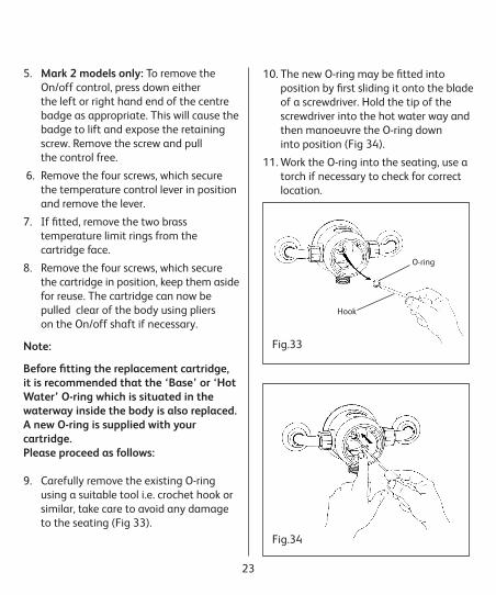
5. Mark 2 models only: To remove the On/off control, press down either the left or right hand end of the centre badge as appropriate. This will cause the badge to lift and expose the retaining screw. Remove the screw and pull the control free.
6. Remove the four screws, which secure the temperature control lever in position and remove the lever.
7. If fitted, remove the two brass temperature limit rings from the cartridge face.
8. Remove the four screws, which secure the cartridge in position, keep them aside for reuse. The cartridge can now be pulled clear of the body using pliers on the On/off shaft if necessary.
Note:
Before fitting the replacement cartridge, it is recommended that the ‘Base’ or ‘Hot Water’ O-ring which is situated in the waterway inside the body is also replaced. A new O-ring is supplied with your cartridge.Please proceed as follows:
9. Carefully remove the existing O-ring using a suitable tool i.e. crochet hook or similar, take care to avoid any damage to the seating (Fig 33).
Fig.33
Hook
O-ring
Fig.34
10. The new O-ring may be fitted into position by first sliding it onto the blade of a screwdriver. Hold the tip of the screwdriver into the hot water way and then manoeuvre the O-ring down into position (Fig 34).
11. Work the O-ring into the seating, use a torch if necessary to check for correct location.

24
12. Apply a smear of silicone lubricant or petroleum jelly to the face of the O-ring.
13. Push your existing four brass cartridge fixing screws through the face of the cartridge and attach the gasket to the screws ensuring that it is correctly positioned (Fig 35).
Note: The plated fixing screws, which are included with your new cartridge, must only be used on later pattern plastic bodies and are not suitable for use with brass bodied valves.
DO NOT ATTEMPT TO USE THESE SCREWS TO SECURE YOUR CARTRIDGE, REUSE YOUR EXISTING BRASS M5 POSIDRIV SCREWS.
14. Offer the cartridge up to the body after checking that the waterway in the rear of the cartridge is in alignment with the waterway, which is situated in the face of the body (Fig 36).
15. Tighten the four fixing screws sufficiently to achieve a watertight seal.
16. Loosely attach the On/off control to the front of the cartridge and turn clockwise to ensure that the shower is fully off, remove the control.
17. Turn on the supplies and check for leaks.
Fig.35
Fig.36
Gasket & screws in position
Cold water way
Fig.37
Temperature limiting holes
18. Set the shower to the mid-blend position by turning the coloured ring until the semi circle of small holes radiate down from twelve o’clock to six o’clock. This operation will be made easier, if a temperature lever fixing screw is first inserted by two or three turns into one of the fixing points (Fig 37).

25
Should you wish to restrict the amount of travel of the temperature control lever to a comfort or safety zone, please refer at this point to ‘Temperature Limit Pins’ on page 34. If this facility is not required then please proceed as follows:
19. With the lever in the vertical position, refit the temperature control using the four M3 Posidriv screws provided. A little more than hand tight will be sufficient, excessive force will result in very stiff operation of the control. 20. Refit the On/off control as appropriate for your model (Fig38).
Fig.38
26
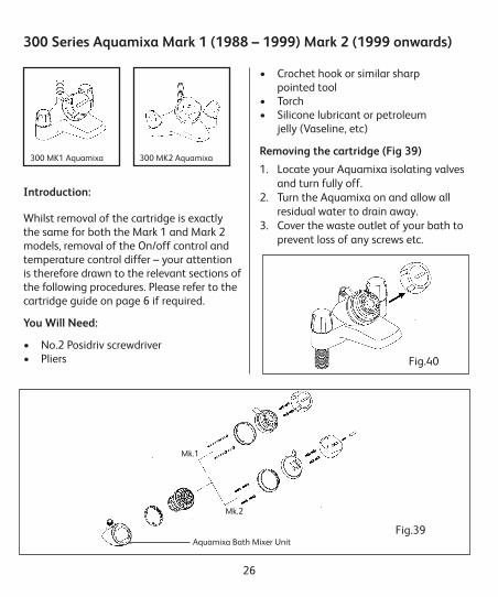
Introduction:
Whilst removal of the cartridge is exactly the same for both the Mark 1 and Mark 2 models, removal of the On/off control and temperature control differ – your attention is therefore drawn to the relevant sections of the following procedures. Please refer to the cartridge guide on page 6 if required.
You Will Need:
• No.2 Posidriv screwdriver • Pliers
• Crochet hook or similar sharp pointed tool • Torch • Silicone lubricant or petroleum jelly (Vaseline, etc)
Removing the cartridge (Fig 39)
1. Locate your Aquamixa isolating valves and turn fully off.2. Turn the Aquamixa on and allow all residual water to drain away.3. Cover the waste outlet of your bath to prevent loss of any screws etc.
300 Series Aquamixa Mark 1 (1988 – 1999) Mark 2 (1999 onwards)
Fig.39
Fig.40
Mk.1
Mk.2
Aquamixa Bath Mixer Unit
300 MK1 Aquamixa 300 MK2 Aquamixa
27
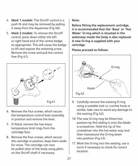
4. Mark 1 models: The On/off control is a push fit and may be removed by pulling it away from the Aquamixa (Fig 40).
5. Mark 2 models: To remove the On/off control, press down either the left or right hand end of the centre badge as appropriate. This will cause the badge to lift and expose the retaining screw. Remove the screw and pull the control free (Fig 41).
6. Remove the four screws, which secure the temperature control lever assembly in position and remove the lever.
7. If fitted, remove the two brass temperature limit rings from the cartridge face.
8. Remove the four screws, which secure the cartridge in position, keep them aside for reuse. The cartridge can now be pulled clear of the body using pliers on the On/off shaft if necessary.
Note:
Before fitting the replacement cartridge, it is recommended that the ‘Base’ or ‘Hot Water’ O-ring which is situated in the waterway inside the body is also replaced. A new O-ring is supplied with your cartridge.
Please proceed as follows:
9. Carefully remove the existing O-ring using a suitable tool i.e. crochet hook or similar, take care to avoid any damage to the seating (Fig 42).
10. The new O-ring may be fitted into position by first sliding it onto the blade a screwdriver. Hold the tip of the screwdriver into the hot water way and then manoeuvre the O-ring down into position (Fig 43).
11. Work the O-ring into the seating, use a torch if necessary to check for correct location.
Fig.41
Fig.42
O-ring
Hook
28
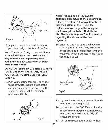
12. Apply a smear of silicone lubricant or petroleum jelly to the face of the O-ring.
Note: The plated fixing screws, which are included with your new cartridge, must only be used on later pattern plastic bodies and are not suitable for use with brass bodied valves.
DO NOT ATTEMPT TO USE THESE SCREWS TO SECURE YOUR CARTRIDGE, REUSE YOUR EXISTING BRASS M5 POSIDRIV SCREWS.
13. Push your existing four brass cartridge fixing screws through the face of the cartridge and attach the gasket to the screws ensuring that it is correctly positioned (Fig 44).
14. Offer the cartridge up to the body after checking that the waterway in the rear of the cartridge is in alignment with the waterway, which is situated in the face of the body (Fig 45).
15. Tighten the four fixing screws sufficiently to achieve a watertight seal.
16. Loosely attach the On/off control to the front of the cartridge and turn clockwise to ensure that the shower is fully off, remove the control.
17. Turn on the supplies and check for leaks.
Fig.43
Fig.44
Fig.45
Gasket & screws in position
Cold water way
Note: If changing a PINK 022802 cartridge, on removal of the old cartridge, if there is a coloured flow regulator fitted into the bottom of the T Tube, the replacement cartridge will also require the flow regulator to be fitted, like for like. Please refer to page 7 for information regarding the fitment of the flow regulator.

29
Should you wish to restrict the amount of travel of the temperature control lever to a comfort or safety zone, please refer at this point to ‘Temperature Limit Pins’ on page 34. If this facility is not required then please proceed as follows:
19. With the lever in the vertical position, refit the temperature control using the four M3 Posidriv screws provided. A little more than hand tight will be sufficient, excessive force will result in very stiff operation of the control. 20. Note: For Mark 1 models with loose temperature ellipses, please ensure that these are replaced red/right and blue/left.21. Refit the On/off control as appropriate for your model (Fig.47).
Fig.46
Temperature limiting holes
Fig.47
18. Set the shower to the mid-blend position by turning the coloured ring until the semi circle of small holes radiate down from twelve o’clock to six o’clock. This operation will be made easier, if a temperature lever fixing screw is first inserted by two or three turns into one of the fixing points (Fig 46).

30
You Will Need:
• No.2 Posidriv screwdriver
• T25 Torx screwdriver or 8mm flat blade screwdriver
• Pliers
• Silicone lubricant or petroleum jelly (Vaseline, etc)
Removing the cartridge
1. Locate your shower isolating valves and turn fully off.
2. Turn the shower on and allow all residual water to drain away.
3. Cover the waste outlet of your bath or tray to prevent loss of any screws etc.
4. Please refer to the main product installation guide for removal of the On/off control knob.
5. Remove the four screws, which secure the temperature control lever in position, depress the safety stop button and remove the lever.
6. Pull the coloured override ring clear.
7. Remove the four screws, which secure the cartridge in position – the cartridge can now be pulled clear of the body using pliers on the On/off shaft if necessary.
8. Carefully ease the white location ring away from the cartridge face.
Note:
Before fitting the replacement cartridge, it is recommended that the ‘Base’ or ‘Hot Water’ O-ring is also replaced. On Axis Thermo, Quartz Thermo and Dream shower valves it is required that the O-ring is fitted onto the T Tube at the rear of the cartridge. Fit the white circlip and black O-ring from the screw pack, onto the T Tube at the rear of the new cartridge, by first sliding the circlip down the shaft until it locks into place, then sliding the O-ring until it sits flush against the circlip.
FITTING THE NEW CARTRIDGE9. Push the four cartridge fixing screws through the face of the cartridge and attach the gasket to the screws ensuring that it is correctly positioned (Fig.49).
Axis Thermo (2003 – current)Quartz Thermo (2005 – current)Dream (2011 – current)
Fig.48
Fig.49
O-ring
White circlip

31
10. Offer the cartridge up to the body after checking that the waterway in the rear of the cartridge is in alignment with the waterway, which is situated in the face of the body (Fig.50).
11. Tighten the four fixing screws sufficiently to achieve a watertight seal.
12. Loosely attach the On/off control to the front of the cartridge and turn clockwise to ensure that the shower is fully off, remove the control.
13. Turn on the supplies and check for leaks.
14. Snap the white location ring into position on the cartridge face noting that the graduations are located on the left hand side (Fig.51).
15. Set the shower to the full cold position by turning the coloured ring fully anti-clockwise. This operation will be made easier, if a temperature lever fixing screw is temporarily inserted by two or three turns into one of the fixing points (Fig.52).
16. Refit the coloured override ring, ensuring that the lip is pushed fully home – it is suggested that it be initially positioned with the indicator at mid point way on the retaining ring graduations (Fig.53).
17. Depress the safety button and refit the temperature control lever in the full cold position, i.e. with the lever in the nine o’clock position and reaffix using
the four M4 Posidriv screws provided. A little more than hand tight will be sufficient, excessive force will result in very stiff operation of the control.
Fig.50
Gasket & screws in position
Cold water way
Fig.51
Graduations to be this side
Fig.52
Fig.53
Indicator to be positioned as shown
32
You Will Need:
• No.2 Posidriv screwdriver
• T25 Torx screwdriver or 8mm flat blade screwdriver
• Pliers
• Silicone lubricant or petroleum jelly (Vaseline, etc)
Removing the cartridge
1. Locate your shower isolating valves and turn fully off.
2. Turn the shower on and allow all residual water to drain away.
3. Cover the waste outlet of your bath or tray to prevent loss of any screws etc.
4. Please refer to the main product installation guide for removal of the On/off control knob.
5. Remove the four screws, which secure the temperature control lever in position.
6. Remove the four screws, which secure the cartridge in position – the cartridge can now be pulled clear of the body using pliers on the On/off shaft if necessary.
Note:
If changing a PINK 022802 cartridge, on removal of the old cartridge, if there is a coloured flow regulator fitted into the bottom of the T Tube, the replacement
cartridge will also require the flow regulator to be fitted, like for like. Please refer to page 7 for information regarding the fitment of the flow regulator.
FITTING THE NEW CARTRIDGE
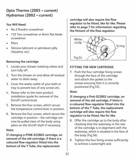
7. Push the four cartridge fixing screws through the face of the cartridge and attach the gasket to the screws ensuring that it is correctly positioned (Fig.55).
Note:
If changing a Pink 022802 cartridge, on removal of the old cartridge, if there is a coloured flow regulator fitted into the bottom of the T Tube, the replacement cartridge will also require the flow regulator to be fitted, like for like.
8. Offer the cartridge up to the body after checking that the waterway in the rear of the cartridge is in alignment with the waterway, which is situated in the face of the body (Fig.56).
9. Tighten the four fixing screws sufficiently to achieve a watertight seal.
Opto Thermo (2005 – current)Hydramax (2002 – current)
Fig.54
O-ring
White circlip

33
10. Loosely attach the On/off control to the front of the cartridge and turn clockwise to ensure that the shower is fully off, remove the control.
11. Turn on the supplies and check for leaks.
12. Set the shower to the mid-blend position by turning the coloured ring until the semi circle of holes radiate down from twelve o’clock to six o’clock. This operation will be made easier, if a temperature lever fixing screw is first inserted by two or three turns into one of the fixing points (Fig.57).
13. With the lever in the vertical position, refit the temperature control using the four M4 Posidriv screws provided. A little more than hand tight will be sufficient, excessive force will result in very stiff operation of the control.
14. Push the On/off control fully home.
Fig.55
Fig.56
Gasket & screws in position
Cold water way
Fig.57
Temperature limiting holes

34
For additional safety, for example where very young or elderly people will be using the shower, the fitting of temperature limit pins may be desirable. The limit pins incorporate an annular groove to facilitate removal of the extension once the desired stop position has been set. These pins are designed to restrict temperature selection to a comfort or safety band.
To restrict movement (Fig 58)
1. Fit a temperature control lever screw into the top threaded hole in the temperature adaptor ring, about four turns should be sufficient.
2. Set the temperature to the mid-blend (twelve o’clock) position.
3. To set the MAXIMUM desired temperature insert a limit pin, turn the adaptor ring clockwise until a stop is reached.
4. Using the temperature control lever screw to assist purchase, turn the adaptor ring clockwise until a stop is reached.
5. Turn the shower on by holding the On/off loosely in place and turning fully anticlockwise, remove the knob. Check that the water is now flowing at the maximum desired temperature. Re-fit knob and turn the shower OFF.
6. If the flow is below the desired temperature, the limit pin will need to be repositioned in a higher hole and the temperature control moved to the new stop position. Check the flow temperature and repeat until correct.7. To set the MINIMUM temperature use the lower set of holes and proceed as above.8. Complete the final assembly as described in the relevant section.
TEMPERATURE LIMIT STOPS
Fig.58
Mid-positionMaximumTemperature
Mid-positionMinimumTemperature
Aqualisa Products Limited,The Flyer’s Way,Westerham, Kent TN16 1DE
Customer helpline: 01959 560010Brochure Hotline: 0800 652 3669Website: www.aqualisa.co.ukEmail: [email protected]
Republic of IrelandSales enquiries: 01-864-3363Service enquiries: 01-844-3212
Part No: 034116 Issue 3 Nov 14
Please note that calls may be recorded for training and quality purposesThe company reserves the right to alter, change or modify the product specifications without prior warning
® Registered Trademark Aqualisa Products Limited