carter hydrant pit valve - api 1584 - eatonpub/@eaton/@aero/...2 eaton aerospace group tf100-86f may...
TRANSCRIPT
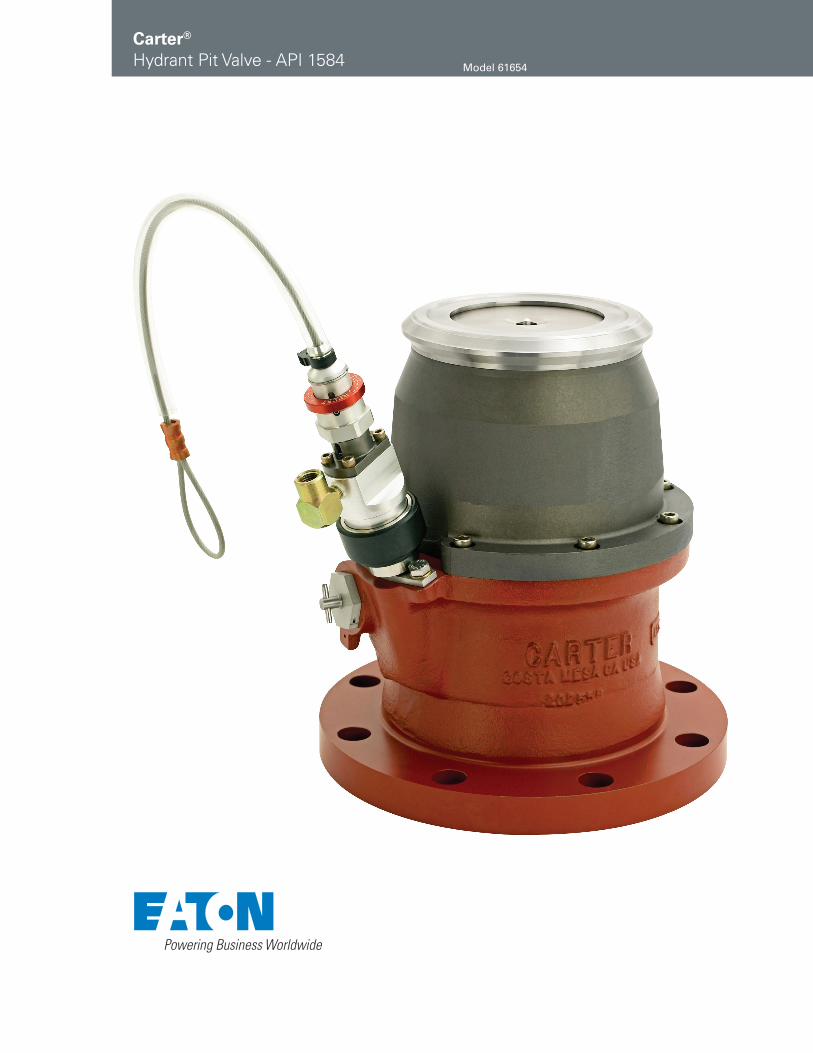
Carter®
Hydrant Pit Valve - API 1584 Model 61654
2 EATON Aerospace Group TF100-86F May 2013
Eaton’s Carter Model 61654 Hydrant Pit Valve is a family of valves that includes lanyard, air or dual air/lanyard operated pilot valves, with the latter available with a defueling option.
The latest Model 61654 Hydrant Pit Valves meet all requirements of API/IP Bulletin 1584, 3rd Edition, including the new breakaway and strength requirements.
The basic hydrant pit valve consists of three basic parts, lower valve assembly, upper valve assembly (or API outlet adapter) and either the standard pilot valve or one of three patented pilot valve actuators (Model 64230, Model 64231 and Model 64280), available as Option X. The lower valve assembly contains an isolation valve which will allow the removal and servicing of the upper valve assembly and the pilot valve assembly while the pit valve is still installed. (See manual SM61654 for proper instructions). The upper portion of all versions of Model 61654 are now furnished with a replaceable part that contains the interface with the hydrant coupler. This minimizes replacement parts expense and allows easy replacement of the outlet wearing surfaces.
Model 61654 Hydrant Pit Valves are essentially identical to Model 60554 valves except for the inlet flange, which is designed to mate with a 6-inch ANSI 150 lb flange rather than a 4-inch flange.
Model 61654 Hydrant Pit Valve is designed to minimize the propagation of surge pressure shocks into the upstream piping system during closure of the valve.
Features
• Standard inlet flange mates with 4-inch 150 lb ANSI flange and outlet adapter in per API Bulletin 1584
• Two-piece upper half standard, replaceable API connection of stainless steel
• Closing time is 2-5 seconds
• New pilotless valve reduces maintenance costs, lanyard, air or dual air/lanyard operated pilot valve available (for small or large pit applications)
• Servicing valve is standard to provide means to remove the upper valve assembly and pilot valve assembly with the unit still installed
• Six position product selection optional
• 10- or 20-mesh screen options available
• All seals are field replaceable
• Large pressure equalizing valve in the outlet is standard
• Defueling capability optional with any air or dual air/lanyard operated pilot
• Ductile iron epoxy coated for corrosion protection
• Main piston well guided to minimize piston seal wear
• Dual pilot adds true dead-man backup to coupler, same as air operated pilot. Hydrant valve is automati-cally closed at the end of the refueling operation. Lanyard operation can also be used with Option X valves.
Model Descriptions
There are five basic valves to which various modifications may be added by option letters as shown in the table on page 4. The five basic units are as follows:
• Model 61654D — Two-piece aluminum/stainless steel API adapter, lanyard operated pilot valve for manual on/off control. Valve allows flow in the fueling direction only. (Defueling possible if outlet pressure does not exceed 21 psig [1.448 bar])
• Model 61654E — Two-piece aluminum/stainless steel API adapter, air operated pilot valve for deadman control. Valve allows flow in the fueling direction only. (Defueling possible if outlet pressure does not exceed 21 psig [1.448 bar])
• Model 61654J — Two-piece aluminum/stainless steel API adapter air operated pilot valve for deadman control with defuel control to allow flow of fuel in either fueling or defueling direction
• Model 61654U — Two-piece aluminum/stainless steel API adapter, dual lanyard/air operated pilot valve. Valve allows flow in the fueling direction only. (Defueling possible if outlet pressure does not exceed 21 psig [1.448 bar] or can be combined with Option J for full flow defuel).
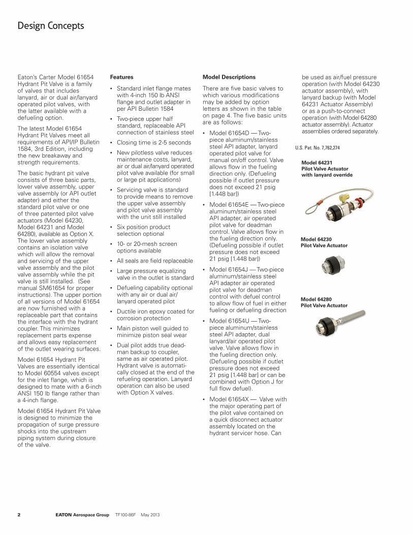
• Model 61654X — Valve with the major operating part of the pilot valve contained on a quick disconnect actuator assembly located on the hydrant servicer hose. Can
Design Concepts
be used as air/fuel pressure operation (with Model 64230 actuator assembly), with lanyard backup (with Model 64231 Actuator Assembly) or as a push-to-connect operation (with Model 64280 actuator assembly). Actuator assemblies ordered separately.
U.S. Pat. No. 7,762,274
Model 64231 Pilot Valve Actuator with lanyard override
Model 64280 Pilot Valve Actuator
Model 64230 Pilot Valve Actuator
EATON Aerospace Group TF100-86F May 2013 3
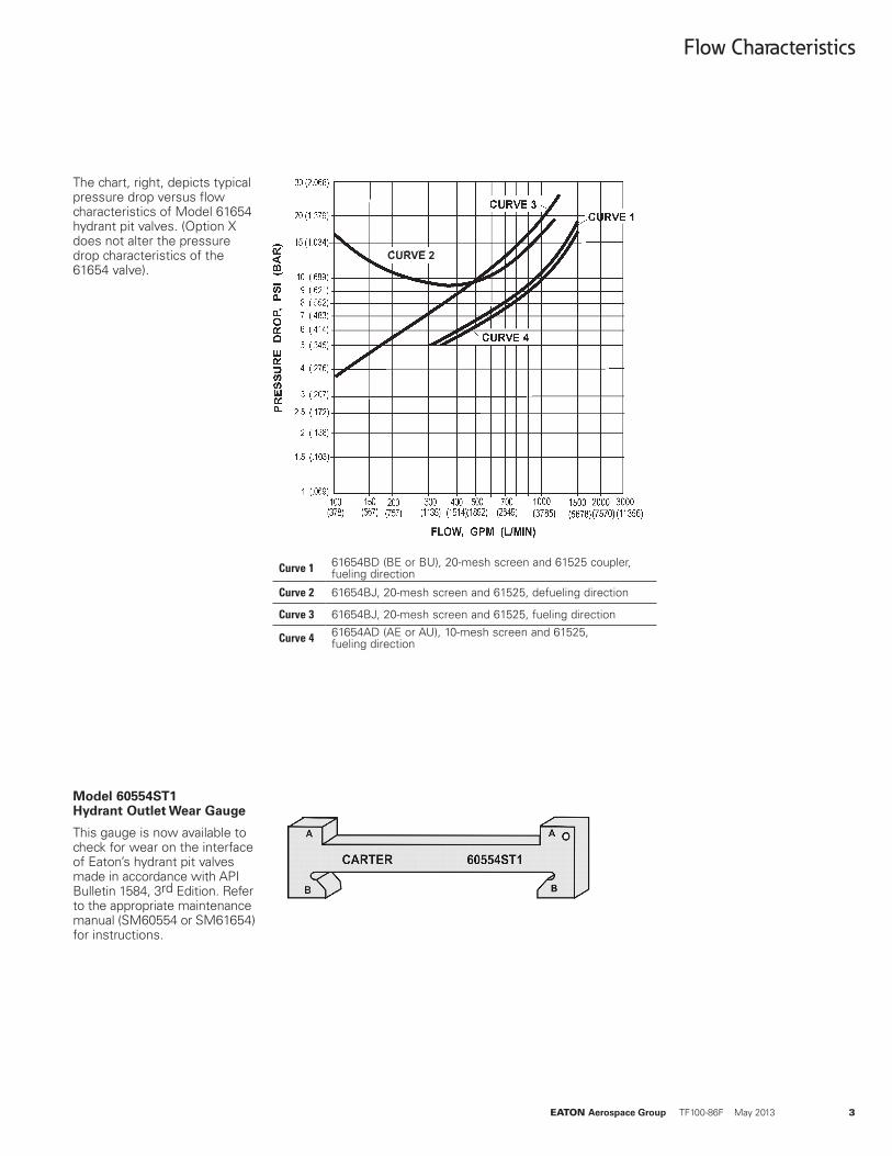
Curve 1 61654BD (BE or BU), 20-mesh screen and 61525 coupler, fueling direction
Curve 2 61654BJ, 20-mesh screen and 61525, defueling direction
Curve 3 61654BJ, 20-mesh screen and 61525, fueling direction
Curve 4 61654AD (AE or AU), 10-mesh screen and 61525, fueling direction
The chart, right, depicts typical pressure drop versus flow characteristics of Model 61654 hydrant pit valves. (Option X does not alter the pressure drop characteristics of the 61654 valve).
Flow Characteristics
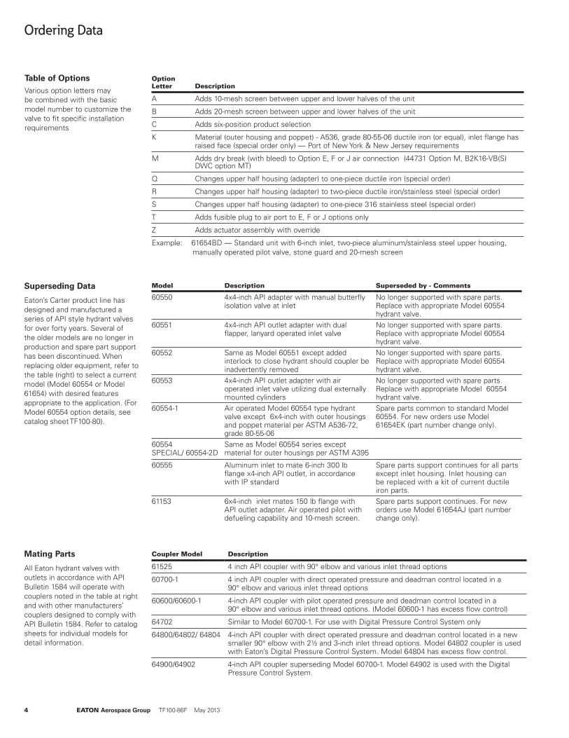
Model 60554ST1 Hydrant Outlet Wear Gauge
This gauge is now available to check for wear on the interface of Eaton’s hydrant pit valves made in accordance with API Bulletin 1584, 3rd Edition. Refer to the appropriate maintenance manual (SM60554 or SM61654) for instructions.
CURVE 2
4 EATON Aerospace Group TF100-86F May 2013
Table of OptionsVarious option letters may be combined with the basic model number to customize the valve to fit specific installation requirements
Option Letter Description
A Adds 10-mesh screen between upper and lower halves of the unit
B Adds 20-mesh screen between upper and lower halves of the unit
C Adds six-position product selection
K Material (outer housing and poppet) - A536, grade 80-55-06 ductile iron (or equal), inlet flange has raised face (special order only) — Port of New York & New Jersey requirements
M Adds dry break (with bleed) to Option E, F or J air connection (44731 Option M, B2K16-VB(S)DWC option MT)
Q Changes upper half housing (adapter) to one-piece ductile iron (special order)
R Changes upper half housing (adapter) to two-piece ductile iron/stainless steel (special order)
S Changes upper half housing (adapter) to one-piece 316 stainless steel (special order)
T Adds fusible plug to air port to E, F or J options only
Z Adds actuator assembly with override
Example: 61654BD — Standard unit with 6-inch inlet, two-piece aluminum/stainless steel upper housing, manually operated pilot valve, stone guard and 20-mesh screen
Ordering Data
Model Description Superseded by - Comments
60550 4x4-inch API adapter with manual butterfly isolation valve at inlet
No longer supported with spare parts. Replace with appropriate Model 60554 hydrant valve.
60551 4x4-inch API outlet adapter with dual flapper, lanyard operated inlet valve
No longer supported with spare parts. Replace with appropriate Model 60554 hydrant valve.
60552 Same as Model 60551 except added interlock to close hydrant should coupler be inadvertently removed
No longer supported with spare parts. Replace with appropriate Model 60554 hydrant valve.
60553 4x4-inch API outlet adapter with air operated inlet valve utilizing dual externally mounted cylinders
No longer supported with spare parts. Replace with appropriate Model 60554 hydrant valve.
60554-1 Air operated Model 60554 type hydrant valve except 6x4-inch with outer housings and poppet material per ASTM A536-72, grade 80-55-06
Spare parts common to standard Model 60554. For new orders use Model 61654EK (part number change only).
60554 SPECIAL/ 60554-2D
Same as Model 60554 series except material for outer housings per ASTM A395
60555 Aluminum inlet to mate 6-inch 300 lb flange x4-inch API outlet, in accordance with IP standard
Spare parts support continues for all parts except inlet housing. Inlet housing can be replaced with a kit of current ductile iron parts.
61153 6x4-inch inlet mates 150 lb flange with API outlet adapter. Air operated pilot with defueling capability and 10-mesh screen.
Spare parts support continues. For new orders use Model 61654AJ (part number change only).
Coupler Model Description
61525 4 inch API coupler with 90° elbow and various inlet thread options
60700-1 4 inch API coupler with direct operated pressure and deadman control located in a 90° elbow and various inlet thread options
60600/60600-1 4-inch API coupler with pilot operated pressure and deadman control located in a 90° elbow and various inlet thread options. (Model 60600-1 has excess flow control)
64702 Similar to Model 60700-1. For use with Digital Pressure Control System only
64800/64802/ 64804 4-inch API coupler with direct operated pressure and deadman control located in a new smaller 90° elbow with 2½ and 3-inch inlet thread options. Model 64802 coupler is used with Eaton’s Digital Pressure Control System. Model 64804 has excess flow control.
64900/64902 4-inch API coupler superseding Model 60700-1. Model 64902 is used with the Digital Pressure Control System.
Mating Parts
All Eaton hydrant valves with outlets in accordance with API Bulletin 1584 will operate with couplers noted in the table at right and with other manufacturers’ couplers designed to comply with API Bulletin 1584. Refer to catalog sheets for individual models for detail information.
Superseding Data
Eaton’s Carter product line has designed and manufactured a series of API style hydrant valves for over forty years. Several of the older models are no longer in production and spare part support has been discontinued. When replacing older equipment, refer to the table (right) to select a current model (Model 60554 or Model 61654) with desired features appropriate to the application. (For Model 60554 option details, see catalog sheet TF100-80).
EATON Aerospace Group TF100-86F May 2013 5
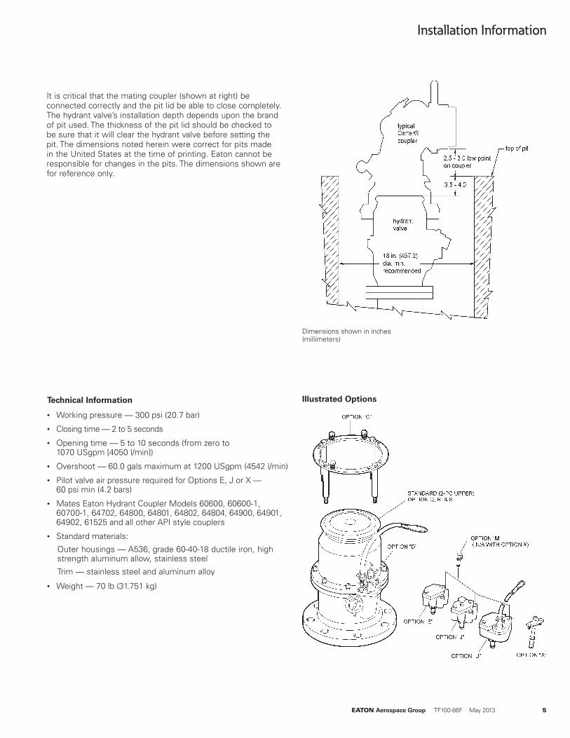
Technical Information
• Working pressure — 300 psi (20.7 bar)
• Closing time — 2 to 5 seconds
• Opening time — 5 to 10 seconds (from zero to 1070 USgpm [4050 l/min])
• Overshoot — 60.0 gals maximum at 1200 USgpm (4542 l/min)
• Pilot valve air pressure required for Options E, J or X — 60 psi min (4.2 bars)
• Mates Eaton Hydrant Coupler Models 60600, 60600-1, 60700-1, 64702, 64800, 64801, 64802, 64804, 64900, 64901, 64902, 61525 and all other API style couplers
• Standard materials:
Outer housings — A536, grade 60-40-18 ductile iron, high strength aluminum allow, stainless steel
Trim — stainless steel and aluminum alloy
• Weight — 70 lb (31.751 kg)
Installation Information
Illustrated Options
It is critical that the mating coupler (shown at right) be connected correctly and the pit lid be able to close completely. The hydrant valve’s installation depth depends upon the brand of pit used. The thickness of the pit lid should be checked to be sure that it will clear the hydrant valve before setting the pit. The dimensions noted herein were correct for pits made in the United States at the time of printing. Eaton cannot be responsible for changes in the pits. The dimensions shown are for reference only.
Dimensions shown in inches (millimeters)
6 EATON Aerospace Group TF100-86F May 2013
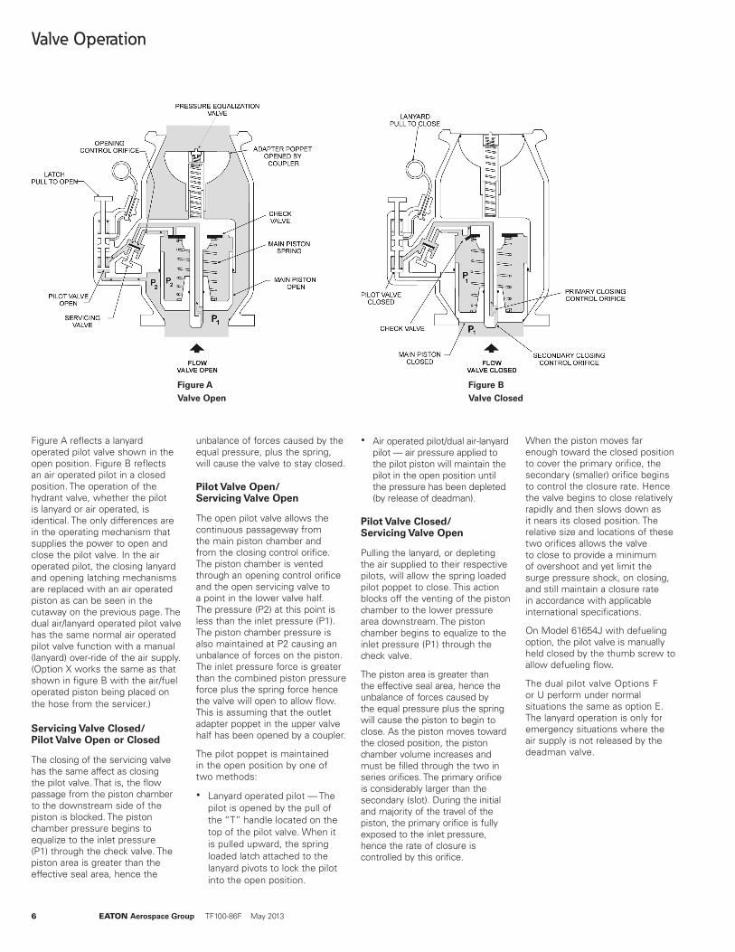
Figure AValve Open
Figure BValve Closed
Valve Operation
Figure A reflects a lanyard operated pilot valve shown in the open position. Figure B reflects an air operated pilot in a closed position. The operation of the hydrant valve, whether the pilot is lanyard or air operated, is identical. The only differences are in the operating mechanism that supplies the power to open and close the pilot valve. In the air operated pilot, the closing lanyard and opening latching mechanisms are replaced with an air operated piston as can be seen in the cutaway on the previous page. The dual air/lanyard operated pilot valve has the same normal air operated pilot valve function with a manual (lanyard) over-ride of the air supply. (Option X works the same as that shown in figure B with the air/fuel operated piston being placed on the hose from the servicer.)
Servicing Valve Closed/ Pilot Valve Open or Closed
The closing of the servicing valve has the same affect as closing the pilot valve. That is, the flow passage from the piston chamber to the downstream side of the piston is blocked. The piston chamber pressure begins to equalize to the inlet pressure (P1) through the check valve. The piston area is greater than the effective seal area, hence the
unbalance of forces caused by the equal pressure, plus the spring, will cause the valve to stay closed.
Pilot Valve Open/ Servicing Valve Open
The open pilot valve allows the continuous passageway from the main piston chamber and from the closing control orifice. The piston chamber is vented through an opening control orifice and the open servicing valve to a point in the lower valve half. The pressure (P2) at this point is less than the inlet pressure (P1). The piston chamber pressure is also maintained at P2 causing an unbalance of forces on the piston. The inlet pressure force is greater than the combined piston pressure force plus the spring force hence the valve will open to allow flow. This is assuming that the outlet adapter poppet in the upper valve half has been opened by a coupler.
The pilot poppet is maintained in the open position by one of two methods:
� Lanyard operated pilot — The pilot is opened by the pull of the “T” handle located on the top of the pilot valve. When it is pulled upward, the spring loaded latch attached to the lanyard pivots to lock the pilot into the open position.
� Air operated pilot/dual air-lanyard pilot — air pressure applied to the pilot piston will maintain the pilot in the open position until the pressure has been depleted (by release of deadman).
Pilot Valve Closed/ Servicing Valve Open
Pulling the lanyard, or depleting the air supplied to their respective pilots, will allow the spring loaded pilot poppet to close. This action blocks off the venting of the piston chamber to the lower pressure area downstream. The piston chamber begins to equalize to the inlet pressure (P1) through the check valve.
The piston area is greater than the effective seal area, hence the unbalance of forces caused by the equal pressure plus the spring will cause the piston to begin to close. As the piston moves toward the closed position, the piston chamber volume increases and must be filled through the two in series orifices. The primary orifice is considerably larger than the secondary (slot). During the initial and majority of the travel of the piston, the primary orifice is fully exposed to the inlet pressure, hence the rate of closure is controlled by this orifice.
When the piston moves far enough toward the closed position to cover the primary orifice, the secondary (smaller) orifice begins to control the closure rate. Hence the valve begins to close relatively rapidly and then slows down as it nears its closed position. The relative size and locations of these two orifices allows the valve to close to provide a minimum of overshoot and yet limit the surge pressure shock, on closing, and still maintain a closure rate in accordance with applicable international specifications.
On Model 61654J with defueling option, the pilot valve is manually held closed by the thumb screw to allow defueling flow.
The dual pilot valve Options F or U perform under normal situations the same as option E. The lanyard operation is only for emergency situations where the air supply is not released by the deadman valve.
EATON Aerospace Group TF100-86F May 2013 7
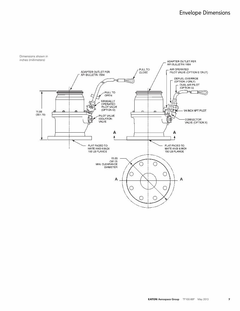
Envelope Dimensions
Dimensions shown in inches (millimeters)

Copyright © 2013 EatonAll Rights ReservedForm No. TF100-86FMay 2013
Eaton Aerospace Group 9650 Jeronimo Road Irvine, California 92618 Phone: (949) 452 9500 Fax: (949) 452 9555 www.eaton.com/aerospace
EatonAerospace GroupFluid & Electrical Distribution Division9650 Jeronimo RoadIrvine, California 92618Phone: (949) 452 9500Fax: (949) 452 9992E-mail: [email protected]