cardiac rhythm management devices (part ii) -...
TRANSCRIPT
� REVIEW ARTICLE
Anesthesiology 2001; 95:1492–1506 © 2001 American Society of Anesthesiologists, Inc. Lippincott Williams & Wilkins, Inc.
Cardiac Rhythm Management Devices (Part II)
Perioperative ManagementJohn L. Atlee, M.D.,* Alan D. Bernstein, Eng.Sc.D.†
IN the first installment of this two-part communication,we reviewed the indications for an implanted pacemakeror internal cardioverter–defibrillator (ICD), provided abrief overview of how a device is selected, and describedthe basics of pacemaker and ICD design and function.Here we discuss specific device malfunction, electro-magnetic and mechanical interference, and managementfor patients with a device or undergoing system implan-tation or revision. As in part I, the NASPE-BPEG (forNorth American Society for Pacing and Electrophysiolo-gy–British Pacing and Electrophysiology Group; some-times abbreviated as NBG) generic pacemaker code isused to designate pacing modes.1
Device Malfunction
Pacemaker MalfunctionPacing malfunction can occur with an implanted pace-
maker or ICD because all contemporary ICDs have atleast a backup single-chamber pacing capability, andmost have dual-chamber pacing as well. Primary pace-maker malfunction is rare, accounting for less than 2% ofall device-related problems in one large center over a6-yr period.2 Some devices have programmed behaviorthat may simulate malfunction, termed pseudomalfunc-tion.3 For example, failure to pace may be misdiagnosedwith programmed rate hysteresis. With rate hysteresis,the pacing cycle duration is longer after a sensed versuspaced depolarization. This encourages the emergence ofintrinsic rhythm. Pacemaker malfunction is classified as
failure to pace, failure to capture, pacing at abnormalrates, undersensing (failure to sense), oversensing, andmalfunction unique to dual-chamber devices (table 1).3,4
To diagnose device malfunction, it is necessary obtain a12-lead electrocardiogram and chest radiograph and tointerrogate the device to check pacing and sensingthresholds, lead impedances, battery voltage, and mag-net rate.3,4
Failure to Pace. With a single-chamber pacemakerand failure to pace, there will be no pacing artifacts inthe surface electrocardiogram. The intrinsic rate will bebelow the programmed lower rate limit, which is ob-tained from the patient’s records or through device in-terrogation.3,4 Misdiagnosis of failure to pace is possibleif the device is inhibited by intrinsic cardiac depolariza-tions not apparent in the surface electrocardiogram.With a dual-chamber device, no pacing artifacts may bepresent, or there may be pacing in only one chamber.With the latter, first it must be determined that thedevice is not programmed to a single-chamber pacingmode. Failure to pace may be intermittent or continuous.
Failure to pace is often due to oversensing (see Over-sensing). Other causes are an open circuit caused by abroken, dislodged, or disconnected lead, lead insulationdefects, or malfunction of other system components. Inaddition, problems with the lead–tissue interface mayexplain failure to pace. When failure to pace occurswithin 48 h of device implantation, lead dislodgement,migration, and myocardial perforation are probablecauses. Misdiagnosis of failure to pace may occur withimpending battery depletion, evidenced by the “electivereplacement indicator.” The elective replacement indi-cator rate is not necessarily the same as the nominallyprogrammed rate. Examples of elective replacement in-dicators are listed in table 3.5 Failure to pace may bemisdiagnosed with too-rapid strip-chart recordingspeeds. If so, the intervals between paced beats appearlonger than normal. Finally, the sense amplifier maydetect isoelectric extrasystoles (i.e., in the surface elec-trocardiogram) that properly inhibit stimulus delivery.
Failure to Capture. With failure to capture, there willbe visible pacing artifacts in the 12-lead surface electro-cardiogram but no or intermittent atrial or ventriculardepolarizations. To confirm this diagnosis, the devicemust be interrogated to examine event markers andmeasured data (e.g., lead impedances and pacing and
This is the second part of a two-part article. Part I appeared inthe November 2001 issue.
*Professor of Anesthesiology, Medical College of Wisconsin. †Adjunct Asso-ciate Professor of Surgery, University of Medicine and Dentistry of New Jersey;Director of Technical Research, Department of Surgery, and Technical Director,Pacemaker Center, Newark Beth Israel Medical Center, Newark, New Jersey.
Received from the Department of Anesthesiology, Medical College of Wiscon-sin, Milwaukee, Wisconsin, and the Department of Surgery, University of Medi-cine and Dentistry of New Jersey, Newark, New Jersey. Submitted for publica-tion September 11, 2000. Accepted for publication June 8, 2001. Support wasprovided solely from institutional and/or departmental sources.
Address reprint requests to Dr. Atlee: Department of Anesthesiology, FroedtertMemorial Lutheran Hospital (East), 9200 West Wisconsin Avenue, Milwaukee,Wisconsin 53226. Address electronic mail to: [email protected]. Individual articlereprints may be purchased through the Journal Web site,www.anesthesiology.org.
Anesthesiology, V 95, No 6, Dec 2001 1492

sensing thresholds).3,4 Event markers will identify therelease of stimuli and recycling of the device by sensedevents. As for causes (table 1), stimulation thresholdsmay rise during lead maturation (2–6 weeks after im-plantation), but this has become far less of a problemsince the introduction of steroid-eluting leads and otherrefinements in lead technology. Nonetheless, pacing
thresholds may continue to rise until they exceed max-imum pulse-generator output (exit block).3 Transient,metabolic, and electrolyte imbalance,6–12 as well asdrugs and other factors,3,13–19 may increase pacingthresholds (table 2), a circumstance explaining pacingfailure. Anesthetic drugs are not a likely cause. It isnotable that addition of equipotent halothane, enflurane,
Table 2. Drugs and Other Factors That Affect or Have No Proven Effect on Pacing Thresholds
Effect Drugs Other factors
Increase pacing threshold Bretylium, encainide, flecainide,moricizine, propafenone, sotalol
Myocardial ischemia and infarction;progression of cardiomyopathy;hyperkalemia; severe acidosis oralkalosis; hypoxemia; after ICDshocks or external cardioversionor defibrillation
Possibly increase pacingthreshold
� Blockers, lidocaine, procainamide,quinidine, verapamil
Myxedema; hyperglycemia
Possibly decrease pacingthreshold
Atropine, catecholamines,glucocorticoids
Pheochromocytoma; hyperthyroidor other hypermetabolic states
No proven effect onpacing threshold
Amiodarone; anesthetic drugs, bothinhalation and intravenous
ICD � internal cardioverter–defibrillator.
Table 1. Categories of Pacemaker Malfunction, with Electrocardiographic Appearance and Likely Cause for Malfunction
Category of Malfunction Electrocardiographic Appearance Cause for Malfunction
Failure to pace For one or both chambers, either nopacing artifacts will be present inthe electrocardiograph, orartifacts will be present for onebut not the other chamber
Oversensing; battery failure; opencircuit due to mechanicalproblems with leads or systemcomponent malfunction; fibrosis atelectrode-tissue interface; leaddislodgement; recording artifact
Failure to capture Atrial or ventricular pacing stimuli orboth are present, with persistentor intermittent failure to capture
Fibrosis at electrode-tissue interface;drugs or conditions that increasepacing thresholds (table 2)
Pacing at abnormal rates 1. Rapid pacing rate (upper ratebehavior)
2. Slow pacing rate (below lowerrate interval)
3. No stimulus artifact; intrinsic ratebelow lower rate interval
1. Adaptive rate pacing; trackingatrial tachycardia; pacemaker-mediated tachycardia; oversensing
2. Programmed rate hysteresis, orrest or sleep rates; oversensing
3. Power source failure; leaddisruption; oversensing
Undersensing (failure tosense)
Pacing artifacts in middle of normalP waves or QRS complexes
Inadequate intracardiac signalstrength; component malfunction;battery depletion; misinterpretationof normal device function
Oversensing Abnormal pacing rates with pauses(regular or random)
Far-field sensing with inappropriatedevice inhibition or triggering;intermittent contact betweenpacing system conductingelements
Malfunction unique todual-chamber devices
Rapid pacing rate (i.e., upper ratebehavior)
Crosstalk inhibition; pacemaker-mediated tachycardia (i.e.,runaway pacemaker; sensor-driventachycardia; tachycardia duringMRI; tachycardia 2° to trackingmyopotentials or atrialtachycardias; and pacemaker-reentrant tachycardia)
MRI � magnetic resonance imaging.
Compiled from Levine3 and Mitrani.4
1493PACEMAKERS AND ICDs
Anesthesiology, V 95, No 6, Dec 2001

or isoflurane to opiate-based anesthesia after cardiopul-monary bypass did not increase pacing thresholds.20
Newer inhalation anesthetics, intravenous agents, nar-cotics, and anesthetic adjuncts have not been shown toaffect thresholds. Finally, failure to capture may be mis-diagnosed because of increased latency, which is thedelay between stimulation and the onset of myocardialdepolarization. Drugs or imbalances that increase pacingthresholds (table 2) may also increase latency.3
Pacing at Abnormal Rates. Abnormal pacing ratesmay be an intended or nonintended device function(table 1).3,4 An apparently abnormal rate may corre-spond to the elective replacement indicator (table 3).Alternatively, output is not visible during bipolar pacingbecause of the low amplitude of bipolar pacing artifacts.Upper rate behavior is normal device function if it oc-curs in response to an adaptive-rate sensor. In a dual-chamber device, upper rate behavior may be due topacemaker-mediated tachycardia or tracking atrial tachy-cardia (see Pacemaker-mediated Tachycardia).
Rarely, very rapid ventricular pacing may be due topacemaker “runaway.” Runaway can occur with a single-or dual-chamber pacemaker, requires at least two systemcomponent failures, and may trigger lethal arrhythmias.3
Newer devices have runaway protection circuits thatlimit the stimulation rate to less than 200 beats/min.Pacemaker runaway is a major challenge.21,22 With se-vere hemodynamic instability, the following measuresmay be considered: (1) connect the pacing leads to anexternal pulse generator and then cut or disconnect theleads from the implanted pulse generator or (2) firstestablish temporary transvenous pacing and then cut ordisconnect the leads.22
Undersensing (Failure to Sense). The cardiac elec-trogram must have adequate amplitude and frequencycontent (slew rate) to be sensed properly.3 A signal withapparently adequate amplitude may be markedly atten-uated by the sense amplifier if it has a reduced slew rate.Therefore, the filtered signal may not be of sufficient sizeto be recognized as a valid event; consequently, under-sensing may occur. Table 4 elaborates on previouslyidentified causes of undersensing.3,4 As with failure tocapture, the onset of undersensing relative to the time ofdevice implantation helps identify the cause. Undersens-ing occurring shortly after implantation may be due to
lead dislodgement or malposition or to cardiac perfora-tion. If it occurs later, it could be due to battery deple-tion, system component failure, or functional undersens-ing (see below). In addition, undersensing may be due toaltered cardiac signal morphology secondary to diseaseprogression; myocardial ischemia or infarction; inflam-matory changes or fibrosis at the lead-tissue interface,transient metabolic or electrolyte imbalance; or the ap-pearance of bundle-branch block or ectopy. Finally, ex-ternal or internal cardioversion or defibrillation may tem-porarily or permanently disable sensing functionbecause of transient saturation of the sense amplifier ordirect damage to circuitry or the electrode–myocardialinterface.
Normal pacemaker function may be misinterpreted asmalfunction because of undersensing.3 For example, re-version to an asynchronous pacing mode during contin-uous interference is necessary to protect the patientagainst inappropriate output inhibition. Other examplesare triggered pacing modes with fusion or pseudofusionbeats. With both, pacing artifacts appear within surfaceelectrocardiographic P waves or QRS complexes. Withfusion, there is simultaneous myocardial activation bypaced and spontaneous depolarizations. With pseudofu-sion, pacing stimuli do not produce myocardial depolar-ization. Fusion or pseudofusion can occur because thepacemaker responds to intracardiac depolarization,which may appear isoelectric in more remote surfaceelectrocardiographic leads. Finally, if too-long refractoryperiods are programmed, intrinsic cardiac events thatshould be sensed and should reset pacemaker timing donot. Therefore, the timing interval in effect will time outwith delivery of a stimulus. This may be ineffective(pseudofusion) or only partially effective (fusion), de-
Table 3. Examples of Elective Replacement Indicators ThatMay Affect the Nominal Rate of Pacing
Stepwise change in pacing rate � the pacing rate changes tosome predetermined fixed rate or some percentage decreasefrom the programmed rate.
Stepwise change in magnet rate � the magnet-pacing ratedecreases in a stepwise fashion related to the remainingbattery life.
Pacing mode change � DDD and DDDR pulse generators mayautomatically revert to another mode, such as VVI or VOO toreduce current drain and extend battery life.
Table 4. Causes for Undersensing (Failure to Sense)
Inadequate signal amplitude or slew rateDeterioration of intrinsic signal over time
Lead maturationInflammation, fibrosis
Progression of cardiac diseaseMyocardial ischemia–infarctionNew bundle branch blockAppearance of ectopic beats
Transient decrease in signal amplitudeAfter cardioversion or defibrillation shocksDrugs, metabolic or electrolyte derangements that increasepacing thresholds (table 2)
Component malfunctionBattery depletionMechanical lead dysfunctionRecording artifact (pseudomalfunction)Misinterpretation of normal device function
Triggered pacing modesFusion and pseudofusion beatsFunctional undersensing (too long refractory periods)
Functional undersensing initiated by oversensing
1494 J. L. ATLEE AND A. D. BERNSTEIN
Anesthesiology, V 95, No 6, Dec 2001

pending on whether the chamber is completely or par-tially refractory at the time, respectively. This is an ex-ample of functional undersensing, because this behaviorcan be corrected by reprogramming.3
Oversensing. Any electrical signal of sufficient ampli-tude and frequency occurring during the pacemakeralert period can be sensed and can reset the timing. Forexample, ventricular depolarization sensed by an atrialdemand pacemaker may cause inappropriate inhibitionof stimulus delivery.23 This is an example of “far-field”sensing. Far-field potentials arise in other cardiac cham-bers or are sensed skeletal myopotentials or other elec-tromagnetic interference (EMI). In a device that providesatrial antitachycardia pacing, far-field sensing of ventric-ular depolarizations may lead to inappropriate deliveryof therapy.24 Far-field sensing of atrial depolarizations byVVI systems is unusual because of the smaller amplitudeof P waves.3 Myopotential inhibition has been reportedwith sensed succinylcholine-induced muscle fascicula-tions.25 Myopotential inhibition is more likely withunipolar systems because of the proximity of the anode(pulse generator housing) to the pectoral muscles, dia-phragm, or abdominal muscles, depending on pulse gen-erator location.3 In addition, intermittent contact be-tween conducting elements of the pacing system maygenerate small potentials, termed “make-and-break” po-tentials. If sensed, these may cause inappropriate outputinhibition. Any of the described oversensing can beconfirmed by programming the pacemaker to an asyn-chronous mode or by magnet application. If the cause isoversensing, regular asynchronous pacing will resume.However, if the oversensing is due to other causes (e.g.,lead-conductor failure, pulse-generator failure, batterydepletion, or an open circuit), there will be no pacing.
Malfunction in Dual-chamber Pacemakers. Crosstalkinhibition and pacemaker-mediated tachycardia are ex-amples of malfunction that is specific to devices thatboth pace and sense in the atria and ventricles.
Crosstalk Inhibition. Crosstalk is the unexpectedappearance in the atrial or ventricular sense channel orcircuit of electrical signals present in the other.3 Forexample, polarization potentials after stimulus deliverymay be sensed in the ventricular channel during unipolaratrial pacing. If interpreted as spontaneous ventricularevents, they can inhibit ventricular output. In the ab-sence of an escape rhythm, there could be asystole, withonly atrial pacing artifacts and P waves visible (fig.1).26–28 Such cross-talk inhibition can be prevented byincreasing the ventricular sensing threshold, decreasingatrial output, or programming a longer ventricular blank-ing period, so long as these provide adequate safetymargins for atrial capture and ventricular sensing. Dur-ing the blanking period, ventricular sensing is disabled toavoid overloading of the sense amplifier by voltage gen-erated by the atrial stimulus. If too short (fig. 1), thisallows the atrial stimulus to be sensed in the ventricularchannel, inappropriately resetting the ventriculoatrial(VA) interval without delivery of ventricular stimuli. Ifcross-talk cannot be prevented, many dual-chamber pace-makers have a cross-talk management feature, referred to inthe pacing industry as nonphysiologic atrioventricular (AV)delay or ventricular safety pacing (fig. 2).3
Pacemaker-mediated Tachycardia. Pacemaker-mediated tachycardia is unwanted rapid pacing causedby the device or its interaction with the patient.3 Pace-maker-mediated tachycardia includes pacemaker run-away; sensor-driven tachycardia; tachycardia during
Fig. 1. Cross-talk inhibition. Immediately after the ventricularblanking period (short rectangle; ventricular channel timingoverlay), the polarization potential after atrial stimulation issensed by the ventricular channel (zigzag interference symbol).This is interpreted as an R wave, resetting the ventriculoatrial(VA) interval and ventricular refractory period (VRP). Withcomplete arterioventricular (AV) block and no escape rhythm,ventricular asystole will occur, with atrial pacing faster than theprogrammed atrial rate. The short vertical lines in the ventriculartiming overlay indicate ventricular stimuli inhibited by resettingof the VA interval. ECG � electrocardiography; PVARP � postven-tricular atrial refractory period. Reprinted with permission fromBernstein AD: Pacemaker timing cycles, American College of Car-diology Learning Center Highlights. Bethesda, American Collegeof Cardiology.
Fig. 2. Nonphysiologic arterioventricular (AV) delay (ventricu-lar safety pacing). Whenever the ventricular channel sensesanything during the initial portion of the programmed AV in-terval (shaded), such as cross-talk interference (zigzag symbol;ventricular timing overlay), a ventricular stimulus is triggeredafter an abbreviated AV interval to prevent asystole. In beat two,a conducted R wave is sensed and treated as cross-talk becausethe device does not distinguish spontaneous from paced beats.However, the triggered ventricular stimulus fails to depolarizerefractory myocardium (black rectangle; ventricular timingoverlay). Furthermore, its premature timing prevents stimula-tion during the T wave. ECG � electrocardiography; PVARP �postventricular atrial refractory period; VRP � ventricular re-fractory period. Reprinted with permission from Bernstein AD:Pacemaker timing cycles, American College of CardiologyLearning Center Highlights. Bethesda, American College ofCardiology.
1495PACEMAKERS AND ICDs
Anesthesiology, V 95, No 6, Dec 2001

magnetic resonance imaging (MRI) or due to trackingmyopotentials or atrial tachydysrhythmias; and pacemak-er-reentrant tachycardia.
Sensor-driven tachycardia. Adaptive-rate devicesthat sense vibration, impedance changes, or the QTinterval may sense mechanical or physiologic interfer-ence to cause inappropriate high-rate pacing (table 5). Itis advised that adaptive-rate pacing be disabled, even ifelectrocautery is not used during surgery.3,29,30
Magnetic resonance imaging. Powerful forces existin the MRI suite, including static magnetic, gradientmagnetic, and radiofrequency fields.31–33 The static mag-netic field may exert a torque effect on the pulse gener-ator or close the magnetic reed switch to produce asyn-chronous pacing. Because devices today contain littleferromagnetic material, the former is considered unlike-ly.33 Pacemaker leads can act as an antenna for thegradient magnetic field and radiofrequency field energyapplied during MRI.34 The gradient magnetic field mayinduce voltage in the pacemaker large enough to inhibita demand pacemaker but unlikely to cause pacing.32 Theradiofrequency field, however, may generate enoughcurrent in the leads to cause pacing at the frequency ofthe pulsed energy (60–300 beats/min).32,33 In dual-chamber pacemakers, this may affect one or both chan-nels.33 Finally, Achenbach et al.31 documented an aver-age temperature increase of 15°C at the electrode tip of25 electrodes exposed to MRI, with a maximum increaseof 63°C.
Tachycardia due to myopotential tracking. Theatrial channel of a unipolar, dual-chamber device thattracks P waves (i.e., programmed to VAT, VDD, or DDD)may sense myopotentials from muscle beneath the pulsegenerator, with triggered ventricular pacing up to theprogrammed maximum atrial tracking rate. This is un-likely with bipolar sensing, currently preferred by manyimplanting physicians.3
Tachycardia secondary to tracking atrial tachy-dysrhythmias. Atrial dysrhythmias, notably atrial fibril-lation or flutter, may be tracked by ventricular pacing ator near the device’s upper rate interval if programmed toan atrial-tracking mode (VAT, VDD, DDD). Medication tosuppress the dysrhythmia or cardioversion may be nec-
essary. In most instances, placing a magnet over thepulse generator to disable sensing (see Response of Pace-maker to Magnet Application) will terminate high-rateatrial tracking.4 Some dual-chamber pacemakers havealgorithms to detect fast, nonphysiologic atrial tachycar-dia and then switch to a nontracking pacing mode (i.e.,automatic mode-switching).35–37 This is a useful featurewith complete AV heart block and susceptibility to in-termittent atrial tachyarrhythmias. Methods to preventhigh rate atrial tracking are shown in figures 3 and 4.
Pacemaker-reentrant tachycardia. Pacemaker-reen-trant tachycardia (PRT) can occur in any dual-chamberpacemaker programmed to an atrial-tracking mode (e.g.,VAT, VDD, DDD). It is a type of reentrant tachycardiathat incorporates the pacemaker in the reentry circuit.The patient must have retrograde VA conductionthrough the AV node or an accessory AV pathway forPRT to occur. Approximately 80% of patients with sicksinus syndrome and 35% of those with AV block haveretrograde VA conduction,38–40 so more than 50% ofpatients receiving dual-chamber pacemakers are suscep-tible to PRT.38 Furthermore, 5–10% of patients withabsent VA conduction at the time of device implantationlater acquire VA conduction.38,41 Normally, PRT is initi-ated by a premature ventricular beat. This conducts tothe atria and is sensed, provided it occurs outside thetotal atrial refractory period. The sensed retrograde Pwave initiates the AV interval, which times out with
Fig. 3. Prevention of high-rate atrial tracking. When sensed Pwaves fall within the postventricular atrial refractory period(PVARP; first beat; short upward vertical line; atrial timing over-lay), it does not trigger ventricular pacing or reset the arterio-ventricular (AV) interval. The next anticipated paced event isatrial stimulation at the end of the ventriculoatrial (VA) interval(second beat; short vertical line; atrial timing overlay). How-ever, as shown, a spontaneous P wave is sensed, and this ini-tiates a new AV interval before the VA interval times out withdelivery of an atrial stimulus. Such intentional failure to track Pwaves within the PVARP produces “n-to-one block” (as shown,2:1 block), limiting the minimum ventricular interval to thesum of the AV interval and PVARP. With AV block, as the atrialrate increases above the maximum tracking rate, only everyother P wave is tracked, halving the paced ventricular rate. Ifstill faster, two or more P waves may fall within the total atrialrefractory period (AV � PVARP) and fail to trigger ventricularstimuli. ECG � electrocardiography; VRP � ventricular refrac-tory period. Reprinted with permission from Bernstein AD:Pacemaker timing cycles, American College of CardiologyLearning Center Highlights. Bethesda, American College ofCardiology.
Table 5. Mechanical or Physiologic Interference in thePerioperative Environment That May Be Sensed To CauseInappropriate High-rate Pacing
Vibration sensor—piezocrystalDirect pressure on device (prone position)Bone hammers and sawsBumpy ride (stretcher; hospital beds)
Impedance-based sensors—minute ventilationHyperventilation during induction of anesthesiaMechanical ventilatorsElectrocauteryEnvironmental 50–60 Hz electrical interference
Evoked QT intervalCatecholamine surge (stress, pain, pheochromocytoma)
1496 J. L. ATLEE AND A. D. BERNSTEIN
Anesthesiology, V 95, No 6, Dec 2001

ventricular stimulation. PRT also occurs when pacedventricular beats are conducted back to the atria totrigger ventricular stimulation (fig. 5). To prevent PRT, alonger postventricular atrial refractory period is pro-grammed,3 but this limits the upper atrial tracking rate ofthe device. For example, some patients have VA conduc-tion times greater than 430 ms.3 Thus, if the postventricu-lar atrial refractory period is 450 ms and the AV interval is150 ms, the total atrial refractory period is 600 ms. Thislimits the maximum paced ventricular rate to 100 beats/min, possibly too slow for an active patient. In some de-vices, the postventricular atrial refractory period can beprogrammed to a longer duration after premature ventric-ular beats to prevent sensing of retrograde P waves. Inaddition, placing a magnet over the pulse generator willterminate PRT in most devices by disabling sensing andproducing asynchronous (DOO) pacing. However, PRTmay recur after the magnet is removed.
Response of Pacemaker to Magnet Application.Most pulse generators respond to magnet application bypacing asynchronously in a device-specific single-cham-ber (SOO) or dual-chamber pacing mode (DOO). (AnSOO device paces a single chamber, either the atrium orthe ventricle.) This corresponds to the programmedmagnet mode.42,43 For example, Thera DR or D devices(Medtronic, Minneapolis, MN) pace SOO or DOO at85 beats/min.43 However, with impending power sourcedepletion, the magnet rate may differ, because it be-comes the end-of-life (EOL) or elective replacement in-dicator. Again, the EOL or elective replacement indicatorrate is characteristic for specific devices (e.g., VOO at65 beats/min for the Thera DR and D devices).43
The first few paced beats after magnet application mayoccur at a rate or output other than that seen later,providing device identification data on the strip-chartelectrocardiographic recording as well as informationregarding integrity of the pulse generator and leads.42
Magnet application during electrocardiographic moni-toring also confirms the ability of the system to capturethe appropriate chamber at the programmed outputsettings.43 In addition, magnets may be useful diagnosti-cally and therapeutically.43 In a patient whose intrinsicrhythm inhibits the device, magnet application mayserve to identify the programmed mode when the cor-rect programmer is not available for telemetry.43 Further-more, with device malfunction due to malsensing, mag-net-initiated asynchronous pacing may temporarilycorrect the problem, confirming the presence of far-fieldsensing, cross-talk inhibition, T-wave sensing, or pace-maker-mediated tachycardia. Finally, in pacemaker-de-pendent patients, magnet application may ensure pacingif EMI inhibits output (e.g., in surgical electrocautery).However, if the device has reverted to an asynchronousinterference mode (fig. 6), the magnet response may notbe the same as when the device is not in the interferencemode.42
Finally, it is widely assumed that placing a magnet overany pacemaker pulse generator will invariably causeasynchronous pacing as long as the magnet remains inplace. However, in some pacemakers, the magnet re-sponse may have been programmed off. In others avariety of magnet responses may have been pro-grammed, some of which do not provide immunity toEMI sensing. In still others, the device will continue topace asynchronously or pacing will cease after a pro-grammed number of intervals.42 Thus, if possible, oneshould determine before EMI exposure which pulse gen-erator is present and what must be done to provide
Fig. 5. Pacemaker-reentrant tachycardia occurs when a prema-ture ventricular beat with retrograde P wave (second beat) re-sets the arterioventricular (AV) interval, triggering a ventricularstimulus earlier than expected (i.e., when the ventriculoarterial[VA] interval times out). Pacemaker-reentrant tachycardia mayalso occur if paced ventricular beats produce retrograde Pwaves. ECG � electrocardiography; PVARP � postventricularatrial refractory period; VRP � ventricular refractory period.Reprinted with permission from Bernstein AD: Pacemaker tim-ing cycles, American College of Cardiology Learning CenterHighlights. Bethesda, American College of Cardiology.
Fig. 4. Alternative prevention for high-rate atrial tracking. Theminimum ventricular interval (VVmin) is lower than in fig. 3 butgreater than the arterioventricular (AV) � postventricular atrialrefractory period (PVARP; atrial channel). When the P-P intervalis between AV � PVARP and VVmin (as shown), the P wave fallsoutside PVARP and is tracked by ventricular pacing, but after anextended AV interval (> AV), because the ventricular stimulus isdelayed until the end of VVmin. Therefore, the interval betweensensed P waves and the ventricular stimulus increases with eachbeat until a P wave falls within PVARP and is not tracked (notshown). This produces “pacemaker” or “pseudo” Wenckebach.ECG � electrocardiography; VRP � ventricular refractory pe-riod. Reprinted with permission from Bernstein AD: Pacemakertiming cycles, American College of Cardiology Learning CenterHighlights. Bethesda, American College of Cardiology.
1497PACEMAKERS AND ICDs
Anesthesiology, V 95, No 6, Dec 2001
protection. If this is not possible, then one can observethe magnet response during EMI to ascertain whetherthere is protection from EMI sensing. During electrocau-tery, for example, if despite magnet application the elec-trocautery triggers rapid pacing or inhibits pacing stimuliin a pacemaker-dependent patient, then the cauterymust be limited to short bursts.
ICD MalfunctionSpecific ICD malfunctions include inappropriate shock
delivery, failure to deliver therapy, ineffective shocks,and interactions with drugs or devices affecting the ef-ficacy of therapy.44–46 Because all ICDs feature single- ordual-chamber pacing, there is potential for pacing mal-function as well (discussed previously).
Inappropriate Delivery of Shocks. Electrical arti-facts consequent to lead-related malfunction may beinterpreted as tachycardia, with inappropriate shockdelivery.46 Electrocautery artifact may be similarly mis-interpreted.47 Rapid supraventricular or nonsustainedventricular tachycardia (VT) may be misdiagnosed assustained VT or ventricular fibrillation (VF),44,46 espe-cially if rate-only criteria are used for diagnosis.48 Finally,R and T wave oversensing during ventricular bradycardiapacing has led to inappropriate shocks.49
Failure to Deliver Therapy or Ineffective Shocks.Magnet application may disable sensing and thereforethe ability to deliver therapy (see Response of an ICD toMagnet Application). Especially after repeated sub-threshold shocks for VF, tachydysrhythmias may be un-dersensed and may be the cause of failure to delivertherapy.50 Exposure to diagnostic radiography or com-puted tomography scanning does not adversely affectshock delivery. Lead-related problems, including con-ductor fracture, lead migration, and lead insulation de-fects, may also be responsible for failure to delivershocks or ineffective shocks.46 Acute myocardial infarc-tion, hypoxia, and severe acid-based or acute electrolyteimbalance may increase defibrillation thresholds, leadingto ineffective shocks.44 Any of the latter could also affectthe rate or morphology of VT and the ability to diagnoseVT. Finally, isoflurane and propofol anesthesia do notaffect defibrillation thresholds.51 The effect of other an-esthetics or drugs used to supplement anesthesia is notknown.
Drug–Device Interactions Affecting Efficacy ofICD Therapy. Antiarrhythmic drugs are prescribedalong with ICDs to suppress (1) recurring sustained VTand the need for frequent shocks; (2) nonsustained VTthat triggers unnecessary shocks and causes prematurepower source depletion; and (3) atrial fibrillation andinappropriate shocks.46 In addition, they may be used toslow VT to make it better tolerated or more amenable totermination by antitachycardia pacing and to slow AVnodal conduction with atrial fibrillation. Possible adverseeffects of combined drug and ICD therapy are that (1)amiodarone slows VT to below the programmed rate-detection threshold; (2) prodysrhythmia (the provoca-tion of new or worse dysrhythmias) occurs with manyantidysrhythmic drugs, increasing the need for shocks;(3) defibrillation thresholds may increase; (4) hemody-namic tolerance of VT may be reduced; (5) possible PR,QRS, or QT interval increases can cause multiple count-ing and spurious shocks; and (6) possible morphologicalterations or reductions in amplitude of cardiac electro-grams may lead to failure to detect VT or VF.44,46,52,53
Lidocaine, long-term amiodarone, class 1C drugs (e.g.,flecainide), and phenytoin increase defibrillation thresh-olds.46 Class 1A drugs (e.g., quinidine) and bretylium donot affect defibrillation thresholds.46
Device–Device Interactions Affecting Efficacy ofTherapy. Formerly, pacemakers were used for brady-cardia and antitachycardia pacing in patients with ICDs.Today, ICDs incorporate both pacing capabilities. How-ever, there still may be an occasional patient with bothdevices.46 Adverse interactions between devices includethe following: (1) sensed pacing artifacts or depolariza-tions lead to multiple counting, misdiagnosis as VT/VF,and unnecessary shocks; (2) antitachycardia pacing arti-facts may be misdiagnosed as VT, triggering shocks; (3)
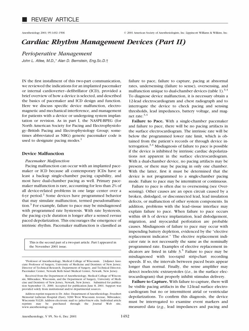
Fig. 6. Asynchronous interference mode in a VVI pacemaker,with temporary VOO pacing at the programmed basic-rate in-terval. The ventricular refractory period (VRP) begins with anoise-sampling period (black rectangles), during which time thesense amplifier is off. During the rest of the VRP, repeated noise(N) above a minimal frequency (e.g., 7 Hz � 420 events/min) isinterpreted as interference and restarts the VRP. Preemptedportions of the VRP are indicated by dashed rectangles. Thus, solong as the noise persists, the device remains refractory, withthe escape timing determined solely by the programmed basic-rate interval (asynchronous pacing at A). Note that a spontane-ous R wave and the second paced beat occur in the noise-sampling period. Neither are sensed, but the latter initiates anew VRP. Reprinted with permission from Bernstein AD: Pace-maker timing cycles, American College of Cardiology LearningCenter Highlights. Bethesda, American College of Cardiology.
1498 J. L. ATLEE AND A. D. BERNSTEIN
Anesthesiology, V 95, No 6, Dec 2001

ICD shocks may reprogram a pacemaker or cause failureto capture or undersensing.46
Response of an ICD to Magnet Application. De-pending on the manufacturer and model of the ICD andhow it is programmed (e.g., magnet switch inactivat-ed54), tachycardia sensing and delivery of therapy maybe inactivated during exposure to a magnet. However,except for CPI devices (CPI, St. Paul, MN), sensing isinhibited only while the magnet is directly over the pulsegenerator.55 With CPI devices, magnet application forless than 30 s temporarily disables sensing, whereas thatlonger than 30 s requires magnet reapplication forlonger than 30 s to reactivate sensing.
Electromagnetic and Mechanical InterferencePacemakers and ICDs are subject to interference from
nonbiologic electromagnetic sources.33 In addition, tem-perature extremes or irradiation may cause malfunction.In general, devices in service today are effectivelyshielded against EMI, and increasing use of bipolar sens-ing has further reduced the problem. EMI frequenciesabove 109 Hz (i.e., infrared, visible light, ultraviolet,x-rays, and gamma rays) do not interfere with pacemak-ers or ICDs because the wavelengths are much shorterthan the device or lead dimensions.33 However, high-intensity therapeutic x-rays and irradiation can directlydamage circuitry.33
EMI enters a pacemaker or ICD by conduction orradiation, depending on whether it is in direct contactwith the source or the leads act as an antenna, respec-tively.33 These devices are protected from EMI by shield-ing the circuitry, reducing the distance between theelectrodes to minimize the antenna (e.g., use of a bipolarvs. unipolar lead configuration for sensing), and filteringincoming signals to exclude noncardiac signals. If EMIdoes enter the pulse generator, noise protection algo-rithms in the timing circuit help reduce its effect on thepatient. However, EMI signals between 5 and 100 Hz arenot filtered because these overlap the frequency range ofintracardiac signals. Therefore, EMI in this frequencyrange may be interpreted by a device as intracardiacsignals, giving rise to abnormal behavior. Possible re-sponses to EMI include (1) inhibition or triggering ofpacing stimulation; (2) asynchronous pacing; (3) moderesetting; (4) damage to the pulse generator circuitry;and (5) triggering of unnecessary ICD shocks.33
Output Inhibition or Triggering and Asynchro-nous Pacing. To protect the pacemaker against inap-propriate inhibition of paced output, some devices willrevert to asynchronous pacing at the basic-rate intervalwhen exposed to continuous EMI above a certain fre-quency (fig. 6). In others, rather than timing out at thebasic-rate interval, repetitive detection of noise in thenoise-sampling period causes temporary reversion to aspecific “noise mode,” typically VOO or DOO.33
Whether EMI noise causes inhibition or asynchronous
pacing depends on signal duration and field strength.56
At the lowest field strength, there is no effect. However,as field strength increases, there is a greater tendency toinhibition because the noise may be sensed intermit-tently. Thus, it may not be sensed in the noise-samplingperiod but in the alert period before the next pacingpulse. With higher field strengths, noise is sensed con-tinuously, and asynchronous pacing occurs. There isconsiderable variation between pacemakers and theirsusceptibility to noise.33,56 Another approach for han-dling EMI is to program a triggered pacing mode (i.e.,VVT, AAT).33 Continuous EMI will then trigger pacing atan upper rate determined by the ventricular or atrial refrac-tory period. This is usually set at approximately 400 ms tolimit the maximum triggered rate to 150 beats/min.
Mode Resetting and Reprogramming. EMI noisemay cause a change to another mode that persists afterthe noise stops.33 This is usually the backup or resetmode, often VVI, and the same as the elective replace-ment indicator or impending battery depletion mode.33
If so, a pacemaker that has been affected by EMI may bewrongly assumed to have reached battery depletion andbe replaced. Alternatively, an operator knowing that adevice has been subject to EMI may reprogram one thathas truly reached battery depletion.33 Some pacemakersmay be reset to the VOO mode, resulting in competitionbetween paced and intrinsic rhythm. To our knowledge,EMI has not reprogrammed ICD antitachycardia thera-pies or affected bradycardia pacing in ICDs with single-or dual-chamber pacing capability. Although randomreprogramming of a pre-1990s pacemaker by electrocau-tery EMI has occurred,57 such reprogramming is highlyunlikely with newer pacemakers, because unique radio-frequency sequences are required to enable program-ming of these devices.
Damage to Circuitry. There can be direct EMI dam-age to pacemaker or ICD circuitry, resulting in outputfailure, pacemaker runaway,21 or other malfunction thatnecessitates pulse generator replacement.33 Pacemakersand ICDs are protected from damage by high-energycurrent or shocks by special circuitry that electronicallyregulates the voltage entering the circuitry and shouldprevent high current from being conducted to the myo-cardium. Even so, extremely high energies may over-come such protection, causing damage to the device orheart. Bipolar devices appear more resistant than unipo-lar devices.33
Triggered Shocks. Reports of inappropriate ICDshocks due to EMI oversensing are infrequent.47 A recentreport described aborted shock delivery in a patientduring facial electrosurgery.58 In this case, EMI was in-terpreted by the device as VF, but spurious shocks wereaverted because the noise did not continue beyond the9-s capacitor charging period.
1499PACEMAKERS AND ICDs
Anesthesiology, V 95, No 6, Dec 2001

Specific Electromagnetic and Mechanical Inter-ference. EMI sources with relevance to perioperativephysicians, along with their potential effects on pace-makers, are listed in table 6.3,33 Although devices pro-grammed to a bipolar lead configuration are more sensi-tive to locally generated signals, they are relativelyinsensitive to more remote signals. The most importantEMI sources are surgical electrocautery and high-energyshocks for cardioversion or defibrillation. Mechanicalventilators and bone hammers or saws may interferewith vibration, acceleration, or minute-ventilation adap-tive-rate pacemakers.
Surgical Electrocautery. The current generated byunipolar electrocautery is related to the distance andorientation of the cautery tool and grounding plate withrespect to the pacemaker or ICD pulse generator andleads.59 The greater the distance, the smaller is the volt-age difference measured by the sensing circuit. Highcurrent is generated in the pulse generator circuitry ifthe cautery cathode (bovie tool) is close to the pulsegenerator, and even higher current is generated if thepulse generator is between the cathode and anode(grounding plate).33 Bipolar cautery produces smallervoltage differences in the sensing circuits. Possibleanomalous behavior with electrocautery EMI is de-scribed in the section Electromagnetic and MechanicalInterference. In addition, electrocautery may overwhelmthe impedance-measuring circuit of a minute ventilationadaptive-rate pacemaker to cause pacing at the upperrate limit.60 Finally, induced currents in the pacing leadsmay cause heating at the electrode-tissue interface, lead-ing to tissue damage and elevated pacing or sensingthresholds. This is infrequently documented and usuallytransient.33
Defibrillator or Cardioverter Shocks. External car-dioversion or defibrillation produces sufficient energynear a pacemaker or ICD to cause damage to the pulsegenerator or electrode–myocardial interface.33 Transientelevation of thresholds for pacing and sensing is not
uncommon after external or internal defibrillation.33
Unipolar pacing systems are more susceptible.33,61 ICDsdeliver smaller amounts of energy but also can interferewith pacemaker function.62 ICD shocks likely will acti-vate the backup or reset modes or the elective replace-ment indicator. However, in devices with programmablelead configuration, unipolar pacing will be delivered bythese modes. Because unipolar pacing pulses are morelikely to be detected by an ICD, it is essential that apacemaker in a patient with an ICD be programmed to abipolar configuration or that the unipolar configurationfirst be tested to ensure there is no undersensing oroversensing by the defibrillator.33 A pacemaker withoutprogrammable lead configurations is preferred for ICDpatients.33
Miscellaneous EMI Sources. In general, it is recom-mended that patients with pacemakers not routinelyundergo MRI.33 Recent studies suggest that MRI may besafe, at least with some models of pacemakers or ICDs,provided the pulse generator and leads are not inside themagnet bore.32,63 If MRI must be performed, programthe device to its lowest voltage and pulse width or to theOOO mode if the patient has adequate spontaneousrhythm.44,64 The pulse waveform should be closely mon-itored in pacemaker-dependent patients, and an externaldefibrillator must be available.33,65,66 Device functionmust be checked after MRI.
Diagnostic radiation has no effect on pacemakers orICDs. Therapeutic radiation did not affect the earliestpacemakers but can cause pulse generator failure innewer pacemakers that incorporate complementarymetal oxide semiconductor–integrated circuit technolo-gy.33,67–69 ICDs may also fail when exposed to radiation.Radiation causes leakage currents between the insulatedparts of the circuit, leading to inappropriate charge ac-cumulation in silicon oxide layers, which eventuallyleads to circuit failure. Therapeutic radiation involvesdoses up to 70 Gy, and pacemakers may fail with as little
Table 6. Potential Sources of Electromagnetic Interference and Their Effects on Pacemakers with Relevance to PerioperativeManagement
EMI SourceGeneratorDamage
CompleteInhibition
One-beatInhibition
AsynchPacing
RateIncrease
Electrocautery Yes Yes Yes Yes Yes*†External DCDF Yes No No Yes YesMRI scanner Possible No Yes Yes YesLithotripsy Yes† Yes‡ Yes‡ Yes‡ Yes§RF ablation Yes Yes No No YesECT No Yes Yes Yes Yes†TENS No Yes No Yes YesRadiation therapy Yes No No No YesDiagnostic radiation No No No No Yes
* Impedance-based adaptive-rate pulse generators. † Piezoelectric crystal-based pulse generators. ‡ Remote potential for interference. § DDD mode only.
Asynch � asynchronous; DCDF � direct current cardioversion or defibrillation; MRI � magnetic resonance imaging; RF � radiofrequency; ECT � electrocon-vulsive therapy; TENS � transcutaneous electrical nerve stimulation.
Compiled from Hayes and Strathmore33 and Levine and Love.3
1500 J. L. ATLEE AND A. D. BERNSTEIN
Anesthesiology, V 95, No 6, Dec 2001

as 10 Gy.33 Failure is unpredictable and may involvechanges in sensitivity, amplitude, or pulse width.33 Inaddition, loss of telemetry, failure of output, or runawayrates may occur.33,70 If unalterable malfunction occurs,replacement of the device is necessary.33,44 Althoughsome changes may resolve in hours, long-term reliabilityof the device is suspect. Before a course of radiationtherapy is begun, the device must be identified and itsfunction evaluated.33,44,67,69,71 Radiation to any part ofthe body away from the site of the pulse generatorshould not cause a problem with the pulse generator,but the pulse generator should be shielded to avoidscatter.33 If this is not possible, the device should beremoved and reimplanted as far as possible from beamsof radiation. The cumulative dose of radiation energy towhich the pulse-generator is exposed should be re-corded after each session. Device function should bemonitored during therapy and regularly evaluated bytelemetry during and after the course of treatment.
Adaptive-rate pacemakers that sense mechanical vibra-tion or acceleration may malfunction during orthopedicsurgery.33 Positive-pressure ventilation may adversely af-fect measurement of minute ventilation by adaptive-ratepacemakers.72–74 Electroconvulsive therapy appears safefor patients with pacemakers since little current flowswithin the heart because of the high impedance of bodytissues.33 However, the seizure may generate sufficientmyopotentials for pacemaker inhibition (unipolar de-vices) or ventricular tracking (adaptive-rate devices).33
Extracorporeal shock wave lithotripsy (ESWL) appearssafe with pacemakers, provided shocks are synchronizedto electrocardiographic R/S waves and dual-chamber de-vices have the cross-talk management feature enabled(fig. 2).33,71 There may be a rate increase in an activity-sensing pacemaker after ESWL shocks. If this is undesir-able, the adaptive-rate feature should be programmedoff. Programming a DDD pacemaker to VVI, VOO, orDOO is advised to avoid irregularities in pacing rate,tracking of ESWL-induced supraventricular tachyarrhyth-mias, or triggering of ventricular output by sensed EMI.33
It is best to disable tachycardia detection during ESWLand to thoroughly test the ICD following the proce-dure.33 Transcutaneous electric nerve stimulation unitsprobably can be used safely in patients with pacemakersor ICDs with bipolar lead polarity.75,76 Nevertheless, it isreasonable to monitor pacemaker or ICD-dependent pa-tients during initial application of transcutaneous elec-tric nerve stimulation. Pacemaker-mediated tachycardiahas been induced by intraoperative somatosensoryevoked potential stimuli.77 Finally, the effects of radio-frequency catheter ablation for termination of tachydys-rhythmias are similar to those of electrocautery andinclude inappropriate inhibition, asynchronous pacing,and reset to a backup pacing mode.78,79
Management for the Patient with a Pacemaker orICDPreoperative Evaluation. Most patients with pace-
makers or ICDs, especially the latter, have significantcardiovascular disease. Many have coexisting systemicdisease as well. Special attention is paid to progression ofdisease, functional status, current medications, and com-pliance with treatment. No special laboratory tests orradiographs are required because the patient has animplanted pacemaker or ICD. However, results of recent12-lead electrocardiography and any indicated diagnosticand recent laboratory tests (e.g., for electrolyte status)should be available.
Device Identification and Evaluation. Unless theproposed surgery or intervention is truly emergent orposes little risk to the pulse generator or leads (e.g.,extremity, ophthalmologic, or other minimally invasivesurgery in which bipolar cautery is used), identify thedevice, as well as date of and indication(s) for its implan-tation. Because all implanted pacemakers and ICDs areprogrammable, device interrogation with a compatibleprogrammer is the most reliable, efficient way to deter-mine function, battery status, programmed settings, pac-ing thresholds, lead impedances, electrode configura-tion, intrinsic rhythm, and magnet response. Theseshould be recorded and rechecked after the surgery orintervention.
Most hospitals today have a pacemaker or ICD clinic orservice (or access to one) that should be consulted fordevice interrogation and reprogramming. For the pace-maker-dependent patient, it is advised that the device bereprogrammed to an asynchronous mode if EMI is likelyto cause significant malfunction (e.g., unipolar electro-cautery for surgery involving the upper abdomen orchest wall). For patients with adaptive-rate devices (in-cluding ICDs), this feature should be programmed offduring surgery or exposure to other EMI that mightcause device malfunction (table 6). Magnet-activatedtesting should be programmed off.42 For patients with anICD, tachycardia sensing should be programmed off.Further, if the patient is also pacemaker-dependent, anasynchronous pacing mode should be programmed ifEMI might cause significant inhibition or other undesiredfunction. After the planned procedure, it is necessary tohave device function tested by qualified personnel, withthe device reprogrammed or replaced if necessary.
In smaller hospitals and freestanding surgical or ambu-latory care facilities, there may be no one immediatelyavailable to perform device interrogation and reprogram-ming. We strongly advise that under no circumstanceshould elective surgery or intervention proceed in thiscircumstance if the patient is at risk for device malfunc-tion that could jeopardize his or her health. In otherwords, just as for the patient with uncontrolled hyper-tension or unstable coronary disease, it is necessary tooptimize the patient’s status before elective surgery or
1501PACEMAKERS AND ICDs
Anesthesiology, V 95, No 6, Dec 2001

intervention. In this case, however, instead of optimizingthe patient’s physical status, the physician is configuringa device to minimize risk for complications related tosystem failure or malfunction. If the planned surgery orintervention is urgent and risk of EMI-related malfunc-tion certain, there still may be time to have the deviceinterrogated and reprogrammed by qualified personnel.The next best strategy for reducing risk is to identify thedevice and contact the manufacturer for suggested man-agement (table 7).
At the time of device implantation, all patients receivea card that identifies the model and serial numbers of thepacemaker or ICD, the date of implantation, and theimplanting physician or clinic (fig. 7). The manufactureralso has this information in its registry. If the patientdoes not have an identification card, the informationshould be in the patient’s medical records. If not, a chestradiograph of the pulse generator area may reveal theunique radiopaque code (i.e., x-ray or radiographic “sig-
natures”) that can be used to identify the manufacturerand model of the device.80 These radiographic signa-tures, which are on most pacemakers and ICDs in exis-tence—as well as other useful information regardingspecific devices, models, and leads (such as NBG codefor functional capability, lead configuration, battery end-of-life or elective replacement indicator, and nominallongevity)—appear in generic reference guides availablefrom all manufacturers listed in table 7. Considerationshould be given to keeping a current guide in the vicinityof the operating suite or preoperative holding area forreference purposes. Once the device has been identi-fied, the manufacturer should be contacted for furtherinformation through its Web site or telephone hotline(table 7).
If the surgery or procedure is truly emergent and it isnot possible to identify the device, basic function ofmost suppressed pacemakers can be confirmed by plac-ing a magnet over the pulse generator to cause asynchro-
Fig. 7. Sample device identification cardsfor a Medtronic Jewel Plus internal car-dioverter–defibrillator (top) and Thera IDR pacemaker (bottom). Front (left) andback (right) of respective cards. With thisinformation, the manufacturer can becontacted through the toll-free numberfor patients (see cards) or via a hotline(table 7) for further advice concerningdevice management. Cards courtesy ofMedtronic, Minneapolis, Minnesota.
Table 7. North American Manufacturers of Pacemakers and ICD, with 24-h Hotlines and Web Sites
Manufacturer Hotline and Website Products
Biotronik, Inc.6024 Jean RoadLake Oswego, Oregon 97035-5369
1-800-547-90011-503-635-9936 (Fax)www.biotronik.com
Single- and dual-chamberpacemakers; single-chamberICD
Guidant Corporation CRM*4100 Hamline Avenue NorthSt. Paul, Minnesota 55112-5798(CPI, Intermedics)
1-800-CARDIAC (227-3422)1-800-582-4166 (Fax)www.guidant.com
Single- and dual-chamberpacemakers (Intermedics,CPI); single- and dual-chamber ICDs (CPI)
Medtronic Corporation7000 Central Avenue NEMinneapolis, Minnesota 55432
1-800-328-25181-800-824-2362 (Fax)www.medtronic.com
Single- and dual-chamberpacemakers; single- and dual-chamber ICDs
St. Jude Medical*Cardiac Rhythm Management Division15900 Valley View CourtSylmar, California 91342(Pacesetter, Ventritex)
1-800-777-22371-800-756-7223 (Fax)www.sjm.com
Single- and dual-chamberpacemakers (Pacesetter);single-chamber ICD (Ventritex)
* Parent company, with recently acquired or merged companies shown below in parentheses.
ICD � internal cardioverter–defibrillator.
1502 J. L. ATLEE AND A. D. BERNSTEIN
Anesthesiology, V 95, No 6, Dec 2001

nous pacing, provided the magnet function has not beenprogrammed off. Cholinergic stimulation (e.g., with Val-salva maneuver, carotid sinus massage, or 6–12 mg in-travenous adenosine) might also be considered to slowthe intrinsic rate sufficiently for release of pacing stimuli.
Perioperative Management: Surgery Unrelated toDevice. The chief concern with perioperative manage-ment for the patient with a pacemaker or ICD is toreduce as much as possible the risk of adverse effectssuch as hemodynamic instability (resulting from inhibi-tion or triggering of pacing stimuli or antitachycardiatherapies) or upper rate pacing behavior. If EMI is likelyto cause device malfunction and the patient does nothave an adequate intrinsic rhythm, the pacemakershould be programmed to an asynchronous mode, pref-erably one that maintains AV synchrony, especially withimpaired ventricular function. If the device is an ICD,tachycardia sensing should be programmed off. If thepatient also requires pacing, an appropriate asynchro-nous mode should be programmed. If a pacemaker orICD also has adaptive-rate pacing, this feature should beprogrammed off.
Because disabling ICD sensing will also prevent deliv-ery of tachycardia therapies, an external cardioverter-defibrillator must be available. If it is not possible toreprogram a device through a compatible programmerand there is significant hemodynamic instability resultingfrom EMI-related malfunction that is largely unavoidable(namely there is massive hemorrhage: surgery is in thevicinity of the pulse generator or leads, and a short burstof electrocautery is impractical), then it is reasonable toplace a magnet directly over the pulse generator of apacemaker. This will cause most devices to pace asyn-chronously until the magnet is removed, unless the mag-net mode has been programmed off. However, somedevices will pace asynchronously only for a programmednumber of intervals.42 As for ICD, without knowingwhat device it is or how it is programmed, or what themagnet response is, it is advised that a magnet not beplaced over the ICD pulse generator to disable tachycar-dia sensing (written communication, David L. Hayes,M.D., Professor of Medicine, Mayo Medical School, Roch-ester, MN, March 2001). Nonetheless, this must be con-sidered if EMI triggers antitachycardia pacing or re-peated shocks that destabilize the patient.
Unipolar electrocautery interference can be reducedby having the grounding plate located as far as possiblefrom the cautery tool.33 The pacemaker or ICD pulsegenerator and leads should not be between the bovietool and grounding plate. Pacing function is confirmedby palpation of the pulse or by monitoring of the heartsounds or pulse waveform (e.g., oximetry or direct arte-rial pressure). Only the lowest possible energies andbrief bursts of electrocautery should be used, especiallywith hemodynamic instability due to related device mal-function. If electrocautery must be used in the vicinity of
(less than 15 cm from) the pulse generator or leads, thedevice should be identified so that its response to sensedcontinuous, strong EMI (i.e., backup or reset mode) willbe known. If the backup pacing mode might compro-mise the patient by reduction of AV synchrony, asyn-chronous pacing, or too slow a rate, a compatible pro-gramming device must be available in the operatingroom, the pulse generator must be accessible to theprogramming head, and someone experienced in pro-gramming should be present.33 Finally, a recent reportsuggests that the ultrasonic scalpel may provide a safealternative to surgical electrocautery.81 However, thisrequires more study before recommendations can bemade. In addition, the ultrasonic scalpel may not beuseful for all types of surgery.
External cardioverter/defibrillator shocks will proba-bly cause at least temporary inhibition. Transient loss ofcapture or sensing should be anticipated, and the stim-ulus amplitude may need to be increased. This is doneautomatically by ICDs with a backup bradycardia pacingcapability71 (virtually all ICDs in service today). Pulsegenerator damage is related to the distance of the exter-nal paddles from the pulse generator. All device manu-facturers recommend the anteroposterior paddle config-uration, with the paddles located at least 10 cm from thepulse generator. Furthermore, it is advised that the low-est possible energies be used for cardioversion or defi-brillation. After cardioversion or defibrillation the pace-maker or ICD must be interrogated to ensure properfunction. Reprogramming or lead replacement may benecessary.33
Perioperative Management: Surgery Related toDevice. Most pacemakers and ICDs have transvenouslead systems. A thoracotomy is no longer required forsystem implantation. Both the pulse generator and leadscan be implanted with use of local anesthesia with con-scious sedation.82–86 However, a thoracotomy and gen-eral anesthesia are required for most infants and smallchildren because epicardial lead systems are still widelyused. General anesthesia or monitored anesthesia careand heavy sedation may be requested in some centers forsystem implantation or revision in adults, especially ifthe procedure involves extensive electrophysiologictesting with repeated induction of tachydysrhythmiasand shocks. Therefore, the following management rec-ommendations must be considered. (1) Temporary pac-ing is advised for disadvantageous bradycardia due to anycause. Alternatively, chronotropic drugs and backup ex-ternal pacing should be available. (2) Reliable pulse mon-itoring (i.e., direct arterial blood pressure monitoring orpulse oximetry) is necessary. Some centers require di-rect arterial blood pressure monitoring.82 (3) For surfaceelectrocardiographic monitoring, select the best leadsfor P waves and ischemia diagnosis. (4) Pulmonary arterycatheters, formerly recommended,47,87,88 are seldomused today because of the widespread use of nonthora-
1503PACEMAKERS AND ICDs
Anesthesiology, V 95, No 6, Dec 2001

cotomy lead systems and smaller pulse generators. Inaddition, pulmonary artery catheters may interfere withICD lead positioning. (5) If the procedure requires mul-tiple defibrillation threshold testing and extensive sub-pectoral dissection, general anesthesia should be consid-ered.82,89 (6) Techniques and drugs for monitoredanesthesia care or general anesthesia vary among insti-tutions. Available inhalation or intravenous agents arenot known to increase defibrillation thresholds90 and areselected more with a view to hemodynamic tolerance.Older volatile agents (halothane, enflurane, and isoflu-rane) affected inducibility of ventricular tachydysrhyth-mias,91–94 which is a consideration during electrophysi-ologic testing. Whether desflurane and sevoflurane havesuch an effect is not known. It is possible that anestheticdrugs could affect the morphology of sensed intracardiacelectrograms, but to our knowledge, this has not beenexamined. Small amounts of lidocaine for vascular accessshould not affect electrophysiologic testing or defibrilla-tion thresholds; larger amounts of lidocaine or bupiva-caine for regional anesthesia (e.g., field blocks) might.90
Although it has not been reported, procaine probablydoes not because it is similar to procainamide, whichalso does not affect defibrillation thresholds.90 (7) Anexternal cardioverter–defibrillator must be available andfunctioning. (8) If the ICD is active at any time duringthe procedure, tachycardia sensing should be disabledwhen unipolar electrocautery is used.
Summary and RecommendationsPerioperative management for patients with cardiac
rhythm management devices may be challenging, giventhe increased sophistication of these devices and thepotential for adverse effects during exposure to electro-magnetic or mechanical interference. Improved shield-ing and increased use of bipolar lead configurations withcurrent devices has reduced the risk of device malfunc-tion during exposure to EMI. Nevertheless, perioperativedevice malfunction is a real possibility without appropri-ate precautions. First, it is necessary to understand whythe device was prescribed and what it is expected to dofor the patient and medical circumstances. Second, basicunderstanding of pacemaker timing and how ICDs de-tect and diagnose dysrhythmias is required for recogni-tion of device malfunction. These considerations areaddressed in the first installment of this article. Hereinwe have discussed specific pacemaker and ICD malfunc-tions and EMIs that are likely to be encountered byanesthesiologists. In addition, we have outlined manage-ment for patients undergoing surgery related or unrelatedto such a device. For the latter, suggested management issummarized in table 8. However, anesthesiologists mustrecognize that this is a very complex and constantly evolv-ing field of technology. It is strongly encouraged that theymake use of resources available to them for advice regard-ing perioperative management issues. Thus, whenever pos-
Table 8. Suggested Management for Patients with Pacemakersor ICD Undergoing Unrelated Surgery
Elective Surgery*Contact pacemaker or ICD clinic or manufacturer during thepreoperative evaluation. Identify and interrogate the device, andreprogram if necessary (i.e., nature or location of plannedsurgery, unipolar cautery, and so on).
With a pacemaker-dependent patient, reprogram the device toa triggered or asynchronous mode. Program magnet-activatedtesting and adaptive-rate pacing off.
With ICD, program tachycardia sensing off. Do not use magnetto disable sensing unless the magnet response is known. Havean external cardioverter–defibrillator available.
If possible, locate the cautery grounding plate so that the pulsegenerator and leads are not in the current pathway between itand the bovie tool. Also, the grounding plate should be locatedas far as possible from the pulse generator and leads. Use thelowest possible cautery energy and short bursts to minimizeadverse effects of EMI.
Monitor arterial pulse waveform and heart sounds to detectEMI-related hemodynamic instability, which is unlikely. Shouldthis occur, proceed as during urgent or emergent surgery(below).
If external defibrillation is required, locate defibrillation pads orpaddles at least 10 cm from the pulse generator and implantedelectrodes. Use apex- (anterior-) posterior position if possible.As near as possible, current flow between the paddles shouldbe perpendicular to the major lead axis.
After surgery, arrange to have device function tested bypacemaker or ICD clinic, and reprogram or replace the device ifnecessary.
Urgent or Emergent Surgery
If time permits, identify the implanted device from the patient’smedical record, identification card, or “x-ray signature.” Contactthe manufacturer (table 7) and follow their recommendations.
Institute electrocardiography and arterial pulse waveform andheart sounds monitoring. If no pacing artifacts are seen and thedevice is a pacemaker, place a magnet over the pulse generatorto determine whether the device is functional. Alternatively,consider a vagal maneuver or drug to slow the intrinsic rate.
If EMI-related pacemaker malfunction is hemodynamicallydestabilizing, program the device to a triggered orasynchronous mode. If this is not possible, a magnet over thepulse generator will convert many (but not all) devices to anasynchronous pacing mode.
If the device is an ICD, without knowing what it is or how it isprogrammed, or what the magnet response is, it is generallyadvised not to place a magnet over the pulse generator todisable tachycardia sensing. However, this should beconsidered if repeated shocks or antitachycardia pacing inresponse to sensed EMI are hemodynamically destabilizing.
After surgery, arrange to have device function tested bypacemaker or ICD clinic, and reprogram or replace the device ifnecessary.
* It is assumed that for patients having elective surgery and at risk for relateddevice malfunction, the pacemaker or ICD clinic or manufacturer will havebeen consulted regarding appropriate perioperative management, includingdevice interrogation and reprogramming if necessary.
ICD � internal cardioverter–defibrillator; EMI � electromagnetic interference.
1504 J. L. ATLEE AND A. D. BERNSTEIN
Anesthesiology, V 95, No 6, Dec 2001

sible, the clinic or service responsible for pacemaker andICD follow-up and the device manufacturers should beconsulted regarding optimal management for specific de-vices and circumstances.
The authors thank David L. Hayes, M.D. (Professor of Medicine, Mayo MedicalSchool, Mayo Clinic, and Mayo Foundation; Consultant, Division of Cardiovascu-lar Diseases and Internal Medicine, Mayo Clinic, Rochester, MN), for his helpfuladvice regarding perioperative management for patients with pacemakers orinternal cardioverter–defibrillators.
References
1. Bernstein AD, Camm AJ, Fletcher RD, Gold RD, Rickards AF, Smyth NP,Spielman SR, Sutton R: The NASPE/BPEG generic pacemaker code for antibrady-arrhythmia and adaptive-rate pacing and antitachyarrhythmia devices. PacingClin Electrophysiol 1987; 10:794–9
2. Parsonnet V, Neglia D, Bernstein A: The frequency of pacemaker-systemproblems, etiologies, and corrective interventions. PACE 1992; 15:510
3. Levine PA, Love CJ: Pacemaker diagnostics and evaluation of pacing systemmalfunction, Clinical Cardiac Pacing and Defibrillation, 2nd edition. Edited byEllenbogen KA, Kay GN, Wilkhoff BL. Philadelphia, WB Saunders, 2000, pp827–75
4. Mitrani RD, Myerberg RJ, Castellanos A: Cardiac pacemakers, Hurst’s TheHeart. Edited by Fuster V, Alexander RW, O’Rourke RA. New York, McGraw-Hill,2001, pp 963–92
5. Untereker DF, Shepard RB, Schmidt CL, Crespi AM, Skarstad PM: Powersystems for implantable pacemakers, cardioverters, and defibrillators, ClinicalCardiac Pacing and Defibrillation, 2nd edition. Edited by Ellenbogen KA, Kay GN,Wilkoff BL. Philadelphia, WB Saunders, 2000, pp 167–93
6. Dohrmann ML, Goldschlager NF: Myocardial stimulation threshold in pa-tients with cardiac pacemakers: Effect of physiologic variables, pharmacologicagents, and lead electrodes. Cardiol Clinics 1985; 3:527–37
7. Gettes LS, Shabetai R, Downs TA, Surawicz B: Effect of changes in potas-sium and calcium concentrations on diastolic threshold and strength-intervalrelationships of the human heart. Ann N Y Acad Sci 1969; 167:693–705
8. Hughes JC Jr, Tyers GF, Torman HA: Effects of acid-base imbalance onmyocardial pacing thresholds. J Thorac Cardiovasc Surg 1975; 69:743–6
9. O’Reilly MV, Murnaghan DP, Williams MB: Transvenous pacemaker failureinduced by hyperkalemia. JAMA 1974; 28:336–7
10. Preston TA, Judge RD: Alteration of pacemaker threshold by drug andphysiological factors. Ann N Y Acad Sci 1969; 167:686–92
11. Schlesinger Z, Rosenberg T, Stryjer D, Gilboa Y: Exit block in myxedema,treated effectively by thyroid hormone therapy. Pacing Clin Electrophysiol 1980;3:737–9
12. Sowton E, Barr I: Physiological changes in threshold. Ann N Y Acad Sci1969; 167:679–85
13. Guarnieri T, Datorre SD, Bondke H, Brinker J, Myers S, Levine JH: In-creased pacing threshold after an automatic defibrillator shock in dogs: Effects ofclass I and class II antiarrhythmic drugs. Pacing Clin Electrophysiol 1988; 11:1324–30
14. Hellestrand KJ, Burnett PJ, Milne JR, Bexton RS, Nathan AW, Camm AJ:Effect of the antiarrhythmic agent flecainide acetate on acute and chronic pacingthresholds. Pacing Clin Electrophysiol 1983; 6:892–9
15. Huang SK, Hedberg PS, Marcus FI: Effects of antiarrhythmic drugs on thechronic pacing threshold and the endocardial R wave amplitude in the consciousdog. Pacing Clin Electrophysiol 1986; 9:660–9
16. Levick CE, Mizgala HF, Kerr CR: Failure to pace following high doseantiarrhythmic therapy: Reversal with isoproterenol. Pacing Clin Electrophysiol1984; 7:252–6
17. Mohan JC, Kaul U, Bhatia ML: Acute effects of anti-arrhythmic drugs oncardiac pacing threshold. Acta Cardiologica 1984; 39:191–201
18. Montefoschi N, Boccadamo R: Propafenone induced acute variation ofchronic atrial pacing threshold: A case report. Pacing Clin Electrophysiol 1990;13:480–3
19. Salel AF, Seagren SC, Pool PE: Effects of encainide on the function ofimplanted pacemakers. Pacing Clin Electrophysiol 1989; 12:1439–44
20. Zaidan JR, Curling PE, Craver JM Jr: Effect of enflurane, isoflurane, andhalothane on pacing stimulation thresholds in man. Pacing Clin Electrophysiol1985; 8:32–4
21. Heller LI: Surgical electrocautery and the runaway pacemaker syndrome.Pacing Clin Electrophysiol 1990; 13:1084–5
22. Mickley H, Andersen C, Nielsen LH: Runaway pacemaker: a still existingcomplication and therapeutic guidelines. Clin Cardiol 1989; 12:412–4
23. Brandt J, Fahraeus T, Schuller H: Far-field QRS complex sensing via theatrial pacemaker lead, I: Mechanism, consequences, differential diagnosis andcountermeasures in AAI and VDD/DDD pacing. Pacing Clin Electrophysiol 1988;11:1432–8
24. Wolpert C, Jung W, Scholl C, Spehl S, Cyran J, Luderitz B: Electrical
proarrhythmia: induction of inappropriate atrial therapies due to far-field R waveoversensing in a new dual chamber defibrillator. J Cardiovasc Electrophysiol1998; 9:859–63
25. Finfer SR: Pacemaker failure on induction of anaesthesia. Br J Anaesth1991; 66:509–12
26. Combs WJ, Reynolds DW, Sharma AD, Bennett TD: Cross-talk in bipolarpacemakers. Pacing Clin Electrophysiol 1989; 12:1613–21
27. De Keyser F, Vanhaecke J, Janssens L, Ector H, De Geest H: Crosstalk withexternal bipolar DVI pacing: A case report. Pacing Clin Electrophysiol 1991;14:1320–2
28. Sweesy MW, Batey RL, Forney RC: Crosstalk during bipolar pacing. PacingClin Electrophysiol 1988; 11:1512–6
29. Schwartzenburg CF, Wass CT, Strickland RA, Hayes DL: Rate-adaptivecardiac pacing: implications of environmental noise during craniotomy. ANESTHE-SIOLOGY 1997; 87:1252–4
30. Seeger W, Kleinert M: An unexpected rate response of a minute ventila-tion dependent pacemaker (letter). Pacing Clin Electrophysiol 1989; 12:1707
31. Achenbach S, Moshage W, Diem B, Bieberle T, Schibgilla V, Bachmann K:Effects of magnetic resonance imaging on cardiac pacemakers and electrodes.Am Heart J 1997; 134:467–73
32. Gimbel JR, Johnson D, Levine PA, Wilkoff BL: Safe performance of mag-netic resonance imaging on five patients with permanent cardiac pacemakers.Pacing Clin Electrophysiol 1996; 19:913–9
33. Hayes DL, Strathmore NF: Electromagnetic interference with implantabledevices, Clinical Cardiac Pacing and Defibrillation, 2nd edition. Edited by Ellen-bogen KA, Kay GN, Wilkhoff BL. Philadelphia, WB Saunders, 2000, pp 939–52
34. Hayes DL, Holmes DR, Jr., Gray JE: Effect of 1.5 tesla nuclear magneticresonance imaging scanner on implanted permanent pacemakers. J Am CollCardiol 1987; 10:782–6
35. Lam CT, Lau CP, Leung SK, Tse HF, Ayers G: Improved efficacy of modeswitching during atrial fibrillation using automatic atrial sensitivity adjustment.Pacing Clin Electrophysiol 1999; 22:17–25
36. Palma EC, Kedarnath V, Vankawalla V, Andrews CA, Hanson S, Furman S,Gross JN: Effect of varying atrial sensitivity, AV interval, and detection algorithmon automatic mode switching. Pacing Clin Electrophysiol 1996; 19:1735–9
37. Ricci R, Puglisi A, Azzolini P, Spampinato A, Pignalberi C, Bellocci F,Adinolfi E, Dini P, Cavaglia S, De Seta F: Reliability of a new algorithm forautomatic mode switching from DDDR to DDIR pacing mode in sinus nodedisease patients with chronotropic incompetence and recurrent paroxysmalatrial fibrillation. Pacing Clin Electrophysiol 1996; 19:1719–23
38. Barold SS: Timing cycles and operational characteristics of pacemakers,Clinical Cardiac Pacing and Defibrillation, 2nd edition. Edited by Ellenbogen KA,Kay GN, Wilkoff BL. Philadelphia, WB Saunders, 2000, pp 727–825
39. Hayes DL, Furman S: Atrio-ventricular and ventriculo-atrial conductiontimes in patients undergoing pacemaker implant. Pacing Clin Electrophysiol1983; 6:38–46
40. Westveer DC, Stewart JR, Goodfleish R, Gordon S, Timmis GC: Prevalenceand significance of ventriculoatrial conduction. Pacing Clin Electrophysiol 1984;7:784–9
41. van Mechelen R, Ruiter J, Vanderkerckhove Y, de Boer H, Hagemeijer F:Prevalence of retrograde conduction in heart block after DDD pacemaker im-plantation. Am J Cardiol 1986; 57:797–801
42. Kutalek SP, Kantharia BK, Maquilan JM: Approach to generator change,Clinical Cardiac Pacing and Defibrillation, 2nd edition. Edited by Ellenbogen KA,Kay GN, Wilkhoff BL. Philadelphia, WB Saunders, 2000, pp 645–68
43. Schoenfield MH: Follow-up of the paced patient, Clinical Cardiac Pacingand defibrillation, 2nd edition. Edited by Ellenbogen KA, Kay GN, Wilkoff BL.Philadelphia, WB Saunders, 2000, pp 895–929
44. Barold S, Zipes D: Cardiac pacemakers and antiarrhythmic devices, HeartDisease, 5th edition. Edited by Braunwald E. Philadelphia, WB Saunders, 1997, pp705–41
45. O’Callaghan PA, Rushkin JN: The implantable cardioverter defibrillator,Hurst’s The Heart, 10th edition. Edited by Fuster V, Alexander RW, O’Rourke RA.New York, McGraw-Hill, 2001, pp 945–62
46. Singer I: Evaluation of implantable cardioverter-defibrillator malfunction,diagnostics, and programmers, Clinical Cardiac Pacing and Defibrillation, 2ndedition. Edited by Ellenbogen KA, Kay GN, Wilkoff BL. Philadelphia, WB Saun-ders, 2000, pp 876–94
47. Gaba DM, Wyner J, Fish KJ: Anesthesia and the automatic implantablecardioverter/defibrillator. ANESTHESIOLOGY 1985; 62:786–92
48. Nunain SO, Roelke M, Trouton T, Osswald S, Kim YH, Sosa-Suarez G,Brooks DR, McGovern B, Guy M, Torchiana DF: Limitations and late complica-tions of third-generation automatic cardioverter-defibrillators. Circulation 1995;91:2204–13
49. Kelly PA, Mann DE, Damle RS, Reiter MJ: Oversensing during ventricularpacing in patients with a third-generation implantable cardioverter-defibrillator.J Am Coll Cardiol 1994; 23:1531–4
50. Natale A, Sra J, Axtell K, Akhtar M, Newby K, Kent V, Geiger MJ, BrandonMJ, Kearney MM, Pacifico A: Undetected ventricular fibrillation in transvenousimplantable cardioverter-defibrillators: Prospective comparison of different leadsystem-device combinations. Circulation 1996; 93:91–8
51. Moerman A, Herregods L, Tavernier R, Jordaens L, Struys M, Rolly G:Influence of anaesthesia on defibrillation threshold. Anaesthesia 1998; 53:1156–9
1505PACEMAKERS AND ICDs
Anesthesiology, V 95, No 6, Dec 2001

52. Greene HL: Interactions between pharmacologic and nonpharmacologicantiarrhythmic therapy. Am J Cardiol 1996; 78:61–6
53. Movsowitz C, Marchlinski FE: Interactions between implantable cardio-verter-defibrillators and class III agents. Am J Cardiol 1998; 82:41I–8I
54. Hunn RH, Ashbaugh TJ, Calderini M, Anderson KP: Multiple inappropriateshocks precipitated by interrogation of an implantable cardioverter defibrillator.Pacing Clin Electrophysiol 1998; 21:1329–30
55. Shah CP, Thakur RK, Xie B, Hoon VK: Implantable cardioverter defibril-lators. Emerg Med Clin North Am 1998; 16:463–89
56. Kaye GC, Butrous GS, Allen A, Meldrum SJ, Male JC, Camm AJ: The effectof 50 Hz external electrical interference on implanted cardiac pacemakers.Pacing Clin Electrophysiol 1988; 11:999–1008
57. Domino KB, Smith TC: Electrocautery-induced reprogramming of a pace-maker using a precordial magnet. Anesth Analgesia 1983; 62:609–12
58. Casavant D, Haffajee C, Stevens S, Pacetti P: Aborted implantable cardio-verter defibrillator shock during facial electrosurgery. Pacing Clin Electrophysiol1998; 21:1325–6
59. Chauvin M, Crenner F, Brechenmacher C: Interaction between permanentcardiac pacing and electrocautery: the significance of electrode position. PacingClin Electrophysiol 1992; 15:2028–33
60. Van Hemel NM, Hamerlijnck RP, Pronk KJ, Van der Veen EP: Upper limitventricular stimulation in respiratory rate responsive pacing due to electrocau-tery. Pacing Clin Electrophysiol 1989; 12:1720–3
61. Levine PA, Barold SS, Fletcher RD, Talbot P: Adverse acute and chroniceffects of electrical defibrillation and cardioversion on implanted unipolar car-diac pacing systems. J Am Coll Cardiol 1983; 1:1413–22
62. Calkins H, Brinker J, Veltri EP, Guarnieri T, Levine JH: Clinical interactionsbetween pacemakers and automatic implantable cardioverter-defibrillators. J AmColl Cardiol 1990; 16:666–73
63. Shellock FG, O’Neil M, Ivans V, Kelly D, O’Connor M, Toay L, Crues JV:Cardiac pacemakers and implantable cardioverter defibrillators are unaffected byoperation of an extremity MR imaging system. AJR Am J Roentgenol 1999;172:165–70
64. Hayes DL, Vlietstra RE: Pacemaker malfunction. Ann Intern Med 1993;119:828–35
65. Garcia-Bolao I, Albaladejo V, Benito A, Alegria E, Zubieta JL: Magneticresonance imaging in a patient with a dual-chamber pacemaker. Acta Cardio-logica 1998; 53:33–5
66. Lauck G, von Smekal A, Wolke S, Seelos KC, Jung W, Manz M, Luderitz B:Effects of nuclear magnetic resonance imaging on cardiac pacemakers. PacingClin Electrophysiol 1995; 18:1549–55
67. Marbach JR, Sontag MR, Van Dyk J, Wolbarst AB: Management of radiationoncology patients with implanted cardiac pacemakers: Report of AAPM TaskGroup No. 34. American Association of Physicists in Medicine. Med Physics 1994;21:85–90
68. Rodriguez F, Filimonov A, Henning A, Coughlin C, Greenberg M: Radia-tion-induced effects in multiprogrammable pacemakers and implantable defibril-lators. Pacing Clin Electrophysiol 1991; 14:2143–53
69. Souliman SK, Christie J: Pacemaker failure induced by radiotherapy. Pac-ing Clin Electrophysiol 1994; 17:270–3
70. Raitt MH, Stelzer KJ, Laramore GE, Bardy GH, Dolack GL, Poole JE,Kudenchuk PJ: Runaway pacemaker during high-energy neutron radiation ther-apy. Chest 1994; 106:955–7
71. Strathmore NF: Interference in cardiac pacemakers, Clinical Cardiac Pac-ing. Edited by Ellenbogen KA, Kay GN, Wilkoff BL. Philadelphia, WB Saunders,1995, pp 770–9
72. Andersen C, Madsen GM: Rate-responsive pacemakers and anaesthesia: Aconsideration of possible implications. Anaesthesia 1990; 45:472–6
73. Madsen GM, Andersen C: Pacemaker-induced tachycardia during generalanaesthesia: A case report. Br J Anaesth 1989; 63:360–1
74. Thiagarajah S, Azar I, Agres M, Lear E: Pacemaker malfunction associatedwith positive-pressure ventilation. ANESTHESIOLOGY 1983; 58:565–6
75. Chen D, Philip M, Philip PA, Monga TN: Cardiac pacemaker inhibition bytranscutaneous electrical nerve stimulation [published erratum appears in ArchPhys Med Rehabil 1990; 71:388]. Arch Phys Med Rehab 1990; 71:27–30
76. Rasmussen MJ, Hayes DL, Vlietstra RE, Thorsteinsson G: Can transcutane-ous electrical nerve stimulation be safely used in patients with permanent cardiacpacemakers? Mayo Clin Proc 1988; 63:443–5
77. Merritt WT, Brinker JA, Beattie C: Pacemaker-mediated tachycardia in-duced by intraoperative somatosensory evoked potential stimuli. ANESTHESIOLOGY
1988; 69:766–878. Ellenbogen KA, Wood MA, Stambler BS: Acute effects of radiofrequency
ablation of atrial arrhythmias on implanted permanent pacing systems. PacingClin Electrophysiol 1996; 19:1287–95
79. Pfeiffer D, Tebbenjohanns J, Schumacher B, Jung W, Luderitz B: Pace-maker function during radiofrequency ablation. Pacing Clin Electrophysiol 1995;18:1037–44
80. Loyd MA, Hayes DL: Pacemaker and implantable cardioverter-defibrillatorradiography, Clinical Cardiac Pacing and Defibrillation. Edited by Ellenbogen KA,Kay GN, Wilkhoff BL. Philadelphia, WB Saunders, 2000, pp 710–23
81. Epstein MR, Mayer JE Jr, Duncan BW: Use of an ultrasonic scalpel as analternative to electrocautery in patients with pacemakers. Ann Thorac Surg 1998;65:1802–4
82. Belott PH, Reynolds DW: Permanent pacemaker and implantable cardio-verter-defibrillator implantation, Clinical Cardiac Pacing and Defibrillation, 2ndedition. Edited by Ellenbogen KA, Kay GN, Wilkoff BL. Philadelphia, WB Saun-ders, 2000, pp 573–644
83. Bubien RS, Fisher JD, Gentzel JA, Murphy EK, Irwin ME, Shea JB, Dick M,2nd, Ching E, Wilkoff BL, Benditt DG: NASPE expert consensus document: use ofi.v. (conscious) sedation/analgesia by nonanesthesia personnel in patients under-going arrhythmia specific diagnostic, therapeutic, and surgical procedures. Pac-ing Clin Electrophysiol 1998; 21:375–85
84. Craney JM, Gorman LN: Conscious sedation and implantable devices: Safeand effective sedation during pacemaker and implantable cardioverter defibrilla-tor placement. Crit Care Nursing Clin North Am 1997; 9:325–34
85. Tung RT, Bajaj AK: Safety of implantation of a cardioverter-defibrillatorwithout general anesthesia in an electrophysiology laboratory. Am J Cardiol1995; 75:908–12
86. van Rugge FP, Savalle LH, Schalij MJ: Subcutaneous single-incision implan-tation of cardioverter-defibrillators under local anesthesia by electrophysiologistsin the electrophysiology laboratory. Am J Cardiol 1998; 81:302–5
87. Cannom DS, Winkle RA: Implantation of the automatic implantable car-dioverter defibrillator (AICD): practical aspects. Pacing Clin Electrophysiol 1986;9:793–809
88. Deutsch N, Hantler CB, Morady F, Kirsh M: Perioperative management ofthe patient undergoing automatic internal cardioverter-defibrillator implantation.J Cardiothoracic Anesth 1990; 4:236–44
89. Moerman A, Herregods L, Foubert L, Poelaert J, Jordaens L, D’Hont L, RollyG: Awareness during anaesthesia for implantable cardioverter defibrillator im-plantation: Recall of defibrillation shocks. Anaesthesia 1995; 50:733–5
90. Kroll MW, Tchou PJ: Testing of implantable defibrillator functions atimplantation, Clinical Cardiac Pacing and Defibrillation. Edited by EllenbogenKA, Kay GN, Wilkhoff BL. Philadelphia, WB Saunders, 2000, pp 540–61
91. Atlee JL III, Bosnjak ZJ: Mechanisms for cardiac dysrhythmias duringanesthesia. ANESTHESIOLOGY 1990; 72:347–74
92. Denniss AR, Richards DA, Taylor AT, Uther JB: Halothane anesthesiareduces inducibility of ventricular tachyarrhythmias in chronic canine myocar-dial infarction. Basic Res Cardiol 1989; 84:5–12
93. Deutsch N, Hantler CB, Tait AR, Uprichard A, Schork MA, Knight PR:Suppression of ventricular arrhythmias by volatile anesthetics in a canine modelof chronic myocardial infarction. ANESTHESIOLOGY 1990; 72:1012–21
94. Hunt GB, Ross DL: Comparison of effects of three anesthetic agents oninduction of ventricular tachycardia in a canine model of myocardial infarction.Circulation 1988; 78:221–6
1506 J. L. ATLEE AND A. D. BERNSTEIN
Anesthesiology, V 95, No 6, Dec 2001