carderock division - defense technical information center · abstract ... the hy-series naval...
TRANSCRIPT

Carderock Division
Naval Surface Warfare Center AD- 26 264Bethesda, Md. 20084-5000 1111111iElfi1!1I 1 11I: 1l11,1lI11111
CARDEROCKDIV-SME-92/64 April 1993
Ship Materials Engineering DepartmentResearch and Development Report
.2 Advances in Lnw Carbon, High StrengthFerrous Alloys2byE.J. Czyryca
M M.G. Vassilaros
X DTIC0 SELECTEc JUN03 199311
S~A
0S
cmI
"93-12442
Approved for public release; distribution Is unlimited.U __ ___ ___ ___ ____ ___ ___I__II_
93 ; .
Carderock DivisionNaval Surface Warfare Center
Bethesda, Md. 20084-5000
CARDEROCKDIV-SME-92/64 April 1993
Ship Materials Engineering DepartmentResearch and Development Report
Advances in Low Carbon, High StrengthFerrous Alloys
byE.J. Czyryca
M. G. Vassilaros
jýCCC-ij o r, f7
I J- . ,' : *... • !
Bytr i'- - .. .. ...
A-i Hbl' c•
I Ol-t • .:t,-
ii~~ ~ it iii
Approved for public release; distribution Is unlimited.
CONTENTS
Page
Paper 1 - "Advances in High Strength Steel Technologyfor Naval Hull Construction
Advances in High Strength Steel Technology for Naval Hull Construction ..... I
Abstract ............................................................ 1
Introduction ........................................................ 2The HY-Series Naval Steels ............................................ 2
HY-Series Steel Fabrication ........................................... 3HSLA-80 Steel Development and Qualification ........................... 5
Weldability of HSLA-80 Steel ......................................... 5HSLA-100 Steel Development and Qualification .......................... 6
HSLA-100 ,Steel Plate Production ...................................... 7
HSLA-100 Steel Certification Program .................................. 8Expansion of the Cu-Strengthened Steel System ........................... 9
Weldability of HSLA-80 And HSLA-100 Steels .......................... 10High Productivity Steel Research and Development ........................ 11
Thermo-Mechanical Controlled Processing ............................... 11
AC/DQ Processing .................................................. 12JLCB Steel Plate Development ........................................ 14
HSLA Technology Summary ........................................... 15
TABLES
1. Specified chemical compositions and mechanical properties ofHY-80, HY-100, and HY-130 steels .................................. 16
2. Specified chemical compositions and mechanical propertiesof HY-80, HSLA-80, HY-100, and HSLA-100 steels .................... 17
3. Chemical composition ranges for HSLA-80/100 steel plate ................. 18
4. Comparison of specified chemical compositions andmechanical properties of HY-100 and HSLA-100 steels toGrade 100 direct quenched (DQ) production steel plate .................... 19
5. Comparison of specified chemical compositions andmechanical properties of HY-100 and HSLA-100 steels toULCB-100 production steel plate .................................... 20
FIGURES
1. Chemical compositions, carbon equivalents, and weldabilitydiagram for high strength naval steels .................................. 21
2. Schematic diagram of the temperature regimes for variationsof TMCP of steels . ................................................ 22
CARDEROCKDIV-SME-92/64 i

3. Chemical compositions, carbon equivalents, andweldability diagram for various 100 ksi steels ............................ 23
R eferences .......................................................... 25
Paper 2 - 'The Development of High-Strength, Cooling-RateInsensitive Ultra-Low-Carbon Weld Metals
The Development of High-Strength, Cooling-Rate InsensitiveUltra-Low-Carbon Weld Metals ........................................ 29
Abstract ............................................................ 29
Introduction ........................................................ 30
High-Strength Steel Welding Products ................................... 31
Weld Metal Property Requirements ..................................... 32
ULCB Steel Plate Development ......................................... 32
ULCB Welding Electrode Development .................................. 33
Sum m ary ........................................................... 35
TABLES
1. Specified chemical compositions and mechanical propertiesfor GMAW/SAW/GTAW wire electrodes, MIL-XXXS type,for welding the HY-series steels ...................................... 36
2. Comparison of specified chemical compositions andmechanical properties of HY-100 and HSLA-100 steels toULCB-100 production steel plate ..................................... 37
3. Change in yield strength (ksi) per % alloying element forexperimental ULCB steels ........................................... 38
FIGURES
1. Strength of as-deposited ULCB weld metal versuscooling rate (welding heat input) ...................................... 38
2a. Effect of simulated multipass welding thermal cycles onULCB weld metal yield strength 0.02 C- 1.5 Mn-4.5 Ni .................. 39
2b. Effect of simulated multipass welding thermal cycles onTLCB weld metal yield strength 0.02 C - 1.5 Mn - 3.5 Mo - 4.0 Ni .......... 39
3. Charpy V-notch impact energy for ULCB weld metals(60 to 100 kJ/nch) ................................................. 40
References .......................................................... 41
iv CARDEROCKDIV-SME--92164
PREFACE
The Metals and Welding Department of Carderock Division (CARDEROCKDIV),Naval Surface Warfare Center participated in the Indo-US Pacific Rim Workshop on"Advances in Low Carbon, High Strength Ferrous Alloys" held in New Delhi, India, 25to 28 March 1992. Dr. O.P. Arora was on the Organizing Committee, Mr. EJ. Czyrycaand Dr. M.G. Vassilaros gave invited presentations on the status of Navy programs onsteel plate and weld metal research and development, respectively. The workshop wasjointly sponsored by Office of Naval Research, Naval Research Laboratory, US ArmyResearch Office - Far East, and the National Metallurgical Laboratory of India. Theworkshop included sessions on low carbon steel research given by government and indus-try representatives from Australia, Japan, and Korea, as well as the US and India, asfollows:
"* Phase Transformation & Strengthening Mechanisms;
"* Structure- Property Correlation;
"* Thermo-mechanical Processing & Intercritical Treatment;
"* Application Areas of Low Carbon Ferrous Alloys; and
"* Fluid Flow & Welding.
The objective of the symposium and workshop meetings was to organize a cooperativeeffort among the participants in areas of common interest for future information ex-change. The workshop concluded with a discussion of on-going and planned Indo-USprojects in steel research with the CARDEROCKDIV and NRL participants,
This report contains papers based on the two presentations. Paper 1 - "Advances inHigh Strength Steel Technology for Naval Hull Construction," by E. J. Czyryca, waspresented by Mr. Czyryca. It covers an overview of US Navy steel plate research pro-grams based on previously cleared and published technical papers. Paper 2 - "TheDevelopment of High-Strength, Cooling-Rate Insensitive Ultra-Low-Carbon Weld Met-als," by M. G. Vassilaros and E. J. Czyryca, was presented by Dr. Vassilaros. It presentsthe status of research in high-strength steel weld metal systems based on ultra-low carbonbainitic (ULCB) metallurgy for systems in the range of 100,000 to 150,000 psi yieldstrength (690 to 1035 MPa). ULCB weld metals show a potential for wire electrode for-mulations for HSLA steel welding, where the as-deposited weld metal strength isindependent of weld metal cooling rate with a good low-temperature toughness.
The Navy has maintained a high strength steel research and development programwith in-house, academic, and industrial research to meet a goal of reducing shipbuildingcosts. Affordability will be a primary consideration in future ship and submarine con-struction programs. The Navy has a vested interest in supporting research anddevelopment of high productivity, high strength steel systems and in benefiting fromcooperative, international technical exchange in steel research.
ADMINISTRATIVE INFORMATION
This report presents summaries of steel plate and welding research and developmentprograms conducted at the Center since 1980, primarily on High Strength, Low Alloy(HSLA) steels and welding of HSLA steels. The CARDEROCKDIV 11SLA Steel Pro-gram has included a wide scope of RDT&E programs, ranging from 6.1 in basic
CARDEROCKDIV-SME-92/64 v

metallurgy, 6.2 efforts in the alloy development of plate and welding products, to 6.3/6.4programs to perform extensive evaluations to certify HSLA steels for ship and submarinestructural applications.
The 6.1 studies were sponsored by the Office of Naval Research under ProgramElement 61153N managed by Dr. G. Yoder. The 6.2 investigations were conducted underboth the Surface Ship and Submarine Materials (Structural) Block Programs, under Pro-gram Element 62234N, managed by Mr. I. L. Caplan, CARDEROCKDIV 0115.
The HSLA-100 programs were jointly sponsored by the SEAWOLF AcquisitionProgram of the Naval Sea Systems Command (NAVSEA PMS 350AT) under ProgramElements 63561N and 64561N, by the Advanced Submarine Research and DevelopmentProgram (NAVSEA 92R) under Program Element 63569N, and by the Aircraft CarrierProgram (NAVSEA PMS 312) under Program Element 64567N.
The technical agent for most of the work described herein was Mr. C. L. Null of theNaval Sea Systems Command (SEA 05M2). The work was conducted under the supervi-sion of Mr. G. A. Wacker, Head, Ship Materials Engineering Department(CARDEROCKDIV 28).
ACKNOWLEDGMENTS
The authors are grateful for the efforts of the many scientists, engineers, technicians,and welders of the Center's Metals and Welding Division who completed the extensiveamount of planning, testing, analysis, and management of the work described herein.
vi CARDEROCKDIV-SME-92/64

ADVANCES IN HIGH STRENGTH STEEL TECHNOLOGY FOR NAVAL HULLCONSTRUCTION
Ernest J. Czyryca
David Taylor Research Center
Bethesda, MD, U.SA. 20084-5000
ABSTRACT
The High-Strength, Low-Alloy (HSLA) steel program was initiated by the U.S. Navyto meet objectives for the reduction of shipbuilding costs by development of more weld-able steels to meet the strength and toughness requirements of HY-80 (540 MPa yieldstrength). HSLA-80 steel is a low carbon, copper precipitation strengthened steel basedon ASTM A710 steel. HSLA-80 has been used in surface ship structural applicationssince 1984, after an evaluation of properties, welding, and structural performance. Asubstantial reduction in hull fabrication costs and higher productivity was achievedthrough substitunton of HSLA--80 for HY-80, with the significant factor in cost savingsbeing the reduction or elimination of preheat for welding.
Based on the HSLA-80 system, HSLA-100 steel was developed to meet or exceedthe strength and toughness of HY-100 steel (690 MPa yield strength) and be weldablewith reduced preheat. HSLA-J00 is also a very low carbon, copper strengthened steel,based on different metallurgical principles than HSLA-80. HSLA-100 has been usedsince 1989 for use in surface combatant structures and ballistic protection as a replace-ment for HY-100 to gain significant cost reductions over a wide range of plate gages.
In addition, research programs continue to explored the properties of thermo -me-chanically processed ultra-low carbon bainitic (ULCB) and accelerated cooled/directquenched (ACIDQ) HSLA steels, with a focus on the feasibility of using these metallurgi-cal concepts to achieve highly weldable naval shipbuilding steels with lower total alloycontent and reduced dependency on heat treatment schedules. These research efforts pro-vide an important step toward the formulation of very high strength steel systems of highfracture toughness, where properties are not restricted to limited fabrication proceduresand plate gages.
KEYWORDS: metallurgy, high-strength steels, welding, mechanical properties,shipbuilding, HY-80, HY-100, HY-130, HSLA-80, HSLA-100.
CARDEROCKDIV--SME-92/64

INTRODUCTION
Modem warship designs in the past two decades have shown a continuing trend ofincreased utilization of high strength, alloy steel plate for weight reduction, increasedpayload, and increased mobility. Naval ship structures are subjected to a complex spec-trum of dynamic loadings in service and stresses built into the hull during fabrication andfit-up. The routine dynamic loads in service include wave loadings, sea slap, slamming,vibration, thermal excursions, cargo buoyancy, aircraft/helicopter landing, and weaponsreactions [1]. The ship structure must operate in both tropical and arctic seas, and, there-fore must be constructed of a steel system with properties to allow reliable operation overa temperature range of about -300 to +1200 F [2].
The structural integrity of the hull must be assured for continuous seakeeping inthese severe environments, as well as in response to the effects of hostile weapons. Thedynamic loadings, particularly in the form of shock waves, must be considered when as-sessing materials performance and fracture safety [3]. The fracture safety of Navy ships isaddressed through the use of structural steels, and welding materials used in hull fabrica-tion must demonstrate high fracture toughness and flaw tolerance for these extremeservice conditions [4].
THE HY-SERIES NAVAL STEELS
The HY (High Yield)-series of steels have been used in U. S. naval warships since1950. HY-80, the first in the series, was developed to achieve the optimum in highstrength and fracture toughness in a welded steel system [5,6]. HY-1 00 and HY-1 30steels were progressively developed to meet increasing strength requirements, whilemaintaining a high fracture toughness.
The HY-series has its origins in the quenched and tempered, Ni-Cr battleship armorsteels produced by the Krupp Steel Works of Germany, circa 1894. The STS armor andpressure hull steels of the 1940's evolved from Krupp armor, and the acronym "HY--0"was applied to a special "Low Carbon STS." The HY steels are metallurgically classifiedas quenched and tempered martensitic steels. These steels have a martensitic microstruc-ture resulting from the combination of alloying (Ni, Cr, Mo, and V) and the heattreatment employed to provide the optimum combination of strength and toughness. Theheat treatment to develop the martensitic structure requires fast cooling from a tempera-ture above 14000 F (austenite range); accomplished in plate, extruded, forged, or castproducts by rapid water quench. The alloying elements promote martensite formation, butthe element with the strongest effect in producing a martensitic structure is carbon. Theas-quenched martensite has high strength and hardness, but is brittle (low toughness) andsusceptible to hydrogen cracking (cold cracking). The optimization of strength and tough-ness is achieved by a tempering heat treatment in the range of 10000 to 12500 F.
During the welding process, the region of the joint near the fusion zone is reheatedinto the austenite range and cools as the welding arc continues deposition of the weldbead. If the joined sections are thick and heat is rapidly conducted away, or welding heatinput is low, cooling rates in the heat-affected zone (HAZ) are high, with conditions fa-vorable for forming untempered martensite after the weld pass, rendering it susceptible toHAZ cracking due to its high hardness. The cooling rates characteristic of arc welding
2 CARDEROCKDIV-SME-92/64
plate gages over 1/2 inch are capable of producing some martensite in almost any carbonsteel '7].
Cold cracking (post-weld cracking, usually below 2v)0" F) is cracking associatedwith dissolved hydrogen and martensitic structure in the HAZ. Underbead cracks (paral-lel to the fusion line), toe cracks (propagating away from the weld toe), and delayedcracking (occurring days after welding) are different types of the same cracking mode,which originate by the same mechanism [7]:
a. Dissolved hydrogen (from shielding gas, flux, electrode coating, or sur-face contamination);
b. Tensile stresses (external restraint, differential expansion during welding,or transformation stress); and
c. Low ductility microstructure (untempered martensite).
One means of avoiding HAZ cracking in a welded high strength steel is a reduction of thecarbon content to levels too low to produce martensite. This requires replacement of car-bon strengthening with expensive alloy additions.
Preheating is an effective means of obviating both HAZ cracking and weld metalcracking. Preheating provides for the following: (1) it lowers the cooling rate to avoidmartensite formation, (2) it provides time and temperature for hydrogen diffusion out ofthe metals, and (3) it lowers the magnitude and rate of shrinkage to reduce residual stress.The combination of a low welding heat input needed to maintain weld metal strength andthe preheat needed to prevent cold cracking results in low productivity welding and hightotal fabrication costs for large structures.
To obtain a weldable steel meeting the strength and toughness requirements, an up-per limit of 0.18 weight % was set for carbon for good weldability, and HY-80 isproperly a "low carbon" alloy steel [5]. The chemical compositions of the HY-series steelplate products are given in Table 1. HY-100 is a modified version of HY-80, typicallyhaving slightly higher C, Ni, Cr, and Mo content for plate of the same gage, and temperedat a lower temperature to gain the increased strength while maintaining toughness andweldability equivalent to HY-80. The carbon content of HY-130 was limited to 0.12%maximum, compared to 0.18% maximum for HY-80, to provide adequate weldability(i.e., better HAZ cracking resistance), but provide sufficient hardenability to achieve amicrostructure of predominantly tempered martensite in heavy gages. The high nickelcontent was needed to ensure the high toughness and survivability required in thick,welded submarine hulls at the minimum service temperature of +300 F. The chromiumand molybdenum additions improved hardenability and promoted the formation of mar-tensite in thick sections, while vanadium provided resistance to softening at thetemperatures required to achieve optimum toughness. Also, low sulphur and phosphoruscontents were required for improved toughness and weldability.
HY-SERIES STEEL FABRICATION
In ship hull construction, welding is the greatest cost driver and largest single ship-yard labor factor. Ship structural fabrication, including materials, welding, andnondestructive evaluation (NDE), can constitute 20% of the total shipbuilding cost. Thewelding department in a shipyard employs twice the labor force of any other single trade.
CARDEROCKDIV-SME-92/64 3

The costs of welding include the welding consumables, the expense of preheat, electrode/flux conditioning and storage, high labor costs due to productivity limitations (heat inputand welding position restrictions), necessity for repair welding, and post-weld soaking toeliminate cracking, when required. Economy demands that, in the construction of such amassive, complex structure as a ship's hull, that weldment properties be achieved "aswelded."
Since the fracture toughness and transition behavior of high strength weld metals isgenerally inferior to that of the parent plate, overmatching weld metal yield strength isrequired for "protecting" the weld metal. In addition to the fracture considerations, otherproduction welding concerns are addressed by the overmatching weld metal strength re-quirement. Electrode, procedure, and welder qualification weldments are fabricated undercontrolled conditions. These quality control items function to minimize variations amongproducts, manufacturers, electrode lots, welders, equipment, etc. The properties of pro-duction welds may vary, depending on the particular welding conditions, and may notduplicate or even closely approach the values prescribed for test welds [8]. Also, weldingin the shipyard production environment may be conducted at less ttian optimum condi-tions for achieving the properties required for the weld metal, and weld defects anddiscontinuities may occur, which detract from the load-carrying capacity of the weldjoint. The concept of overmatching weld metal is also intended tc -ompensate for thispossible strength loss.
The welding heat input is indicative of the weld metal deposition rate for a weldingprocess, and therefore is directly related to the cost to fabricate a structure. The limits onheat input are established by those parameters necessary to provide niinimum strengthand toughness, crack-free weld metal and HAZ, and operability of the welding process(the ability to make a good fusion joint). A high preheat restricts the maximum heat inputin order to result in a weld metal cooling rate sufficient to achieve satisfactory weld metalmechanical properties. With a reduced heat input, more welding passes are required tofabricate a weld joint. This results in higher fabrication costs due to the labor time re-quired to complete the structure as a result of the decrease in weld metal deposition rate.The energy costs associated with welding preheat exceeded the cost of all other energyconsumed in shipyards engaged in submarine construction. Other costs and reduction inproductivity associated with the mandatory use of welding preheat include: (1) capitaland replacement costs for heaters, (2) labor c )sts for installation and removal of heaters,and (3) higher cost to remove/repair the thousands of temporary attachments employedduring ship construction. Additional indirect costs associated with the preheat require-ment include the disruption of other shipyard trade functions, reduced welderproductivity from heat (especially in hot weather and in enclosed and/or limited-accessareas), and inspection delays while the structure is allowed to cool.
A reduction in preheat temperature can increase productivity by increasing the op-erational envelope (range of satisfactory welding conditions) of the welding process. Forexample, the welding process can impart a large quantity of energy to the work piece us-ing heat inputs up to 100 kJAnwh for HY-80 thick section applications. This energycauses the temperature of the weld joint to increase. By beginning with a lower preheattemperature, continuous welding can t e maintained for a longer period of time before themaximum interpas' temperature (3000 F) is exceeded and the weld joint must be allowedto cool between weld passes. The maximum allowable interpass temperature of 3000 F is
4 CARDEROCKDIV-SME-92164

imposed to ensure a minimum weld metal cooling rate for satisfactory mechanical prop-erties of the weld metal. The tensile properties have been found to be particularlysensitive to the weld metal cooling rate. As the weld metal cooling rate decreases, theyield strength is found to decrease for the welding consumables employed for high yieldstrength steels.
HSLA-80 STEEL DEVELOPMENT AND QUALIFICATION
The HSLA steel development program identified ASTM A710 steel, a very low car-bon, copper precipitation strengthened steel, as the prime candidate among a number ofcandidate commercial HSLA steel plate products. The evaluation program demonstratedthat A710, Grade A met a minimum yield strength requirement of 80,000 psi yieldstrength through 3/4 inch gage, had high Charpy V-notch impact energy at low tempera-tures, and excellent weldability [9]. A710 steel was selected since it was in commercialproduction, and short-term modification could result in an easily weldable replacementfor HY-80.
The A710 alloy steel was leveloped by the International Nickel Company to pro-vide a field-weldable, high strength steel with good low-temperature fracture toughnessfor Arctic pipeline applications. Other steels considered included low-carbon, controlled-rolled and quenched and tempered HSLA pipeline steels, which typically could not meetthe minimum Charpy V-notch impact toughness requirement of 35 ft-lbs at -1200 F.HSLA-80 is a ferritic steel. The microstructure of the quenched and aged plate product isgenerally an acicular ferrite in gages less than about 1/2 inch, but polygonal ferrite inthicker plate [10,11]. Ferritic steels are widely used in civil construction because of theirexcellent weldability.
In 1984, HSLA-80 steel was certified for use in ship construction. Certification re-quires an evaluation of a structural fabrication system which demonstrates that the systemwill meet all aspects of structural performance equivalent to or better than the system itreplaces. Material specifications and fabrication/inspection documents are based on theresults of the certification program. An extensive evaluation of HSLA-80 properties,welding, and structural performance [9] demonstrated that the very low carbon, copperprecipitation strengthened steei met the requirements of HY-80 steel, and was readilyweldable with no pr :heat (320 F maximum) using the same welding consumables andprocesses as for HY-80 steel fabrication.
WELDABILITY OF HSLA-80 STEEL
As noted, the primary reason for preheat in the welding of the HY-series steels wasto mitigate underbead cracking (hydrogen related) in the hard, martensitic heat affectedzone (HAZ). The HAZ of the very low carbon, copper-strengthened HSLA-80 steel doesnot significantly harden, but may soften, due to the dissolution of copper and grain coars-ening caused by the heat of welding [12]. HSLA steel HAZ microstructures are lesssensitive to hydrogen cracking, and thus achieve exceUllsnt welciability. The very low-car-bon HAZ in HSLA -80 weldments resulted in a highly weldable steel, insensitive tohydrogen cracking.
Welding process development, weldability, and shipyard producibility studies wereconducted in the HSLA-80 steel certification program for the thickness range of
CARDEROCKDIV-SME--92/64 5

HSLA-80 plate from 1/4 to 3/4 inch were evaluated, and HSLA-80 steel exhibited excel-lent weldability for a broad range of welding conditions and processes. Overall,HSLA-80 steel was found to be superior to or at least equivalent to HY-80 steel in everyaspect of ship fabrication. Welding consumables specifically for welding HSLA-80 werenot developed. The welding consumables qualified for welding HY-80 steel were utilizedfor all welding processes. A summary of the salient features of HSLA-80 welding was asfollows:
Both hot cracking and cold cracking resistance of HSLA-80 steel, whenwelded with "HY-80 type" consumables, was superior to HY-80welded under equivalent conditions.
Preheatfmterpass temperature and electrode handling requirements forHSLA-80 applications are less stringent than for HY-80 welding.
The FCAW, SAW, SMAW, and GMAW processes may be applied satis-factorily over the whole range of welding operating conditions as longas the nominal weld metal cooling rate is 100 F/sec or higher. The re-quirement, the same for HY-80, assures weld metal yield strength abovethe minimum at high heat input levels, for thin plate, and for high pre-heat/interpass temperatures. The minimum preheat and interpasstemperature for welding HSLA-80 was 60:F for critical applicationsand 320 F for general structural welding.
The relative fabricability and repairability of HSLA-80 in a shipyard productionenvironment were established and demonstrated that significant fabrication cost reduc-tions vice HY-80 welding could be achieved [13). The primary factor was the costreduction and improved productivity associated with preheat eliminat on. Over 20,000plate-tons of HSLA-80 steel to MIL-S-24645 have been delivered for use in ship (;on-struction. Production has primarily been in plate gages up through 3/4 inch.
HSLA-100 STEEL DEVELOPMENT AND QUALIFICATION
Following the HSLA--0 program, an alloy development and qualification programcommenced which resulted in HSLA-100 steel as a replacement for HY-100 in ord,ýr toreduce fabrication costs. HSLA-100 is also a very low carbon, copper precipitationstrengthened steel, based on different metallurgical principles than HSLA-80, meetingthe strength and toughness of HY-100 steel, but weldable without the preheat require-ments of HY-100, using the same welding consumables and processes as used in weldingHY-100.
The program for the development of HSLA-100 steel consisted of three phases: (1)laboratory alloy design; (2) trial plate production; and (3) plate production for the certifi-cation program. The composition of the steel was formulated from a progressiveoptimization invclving more than 40 laboratory-scale heats. Laboratory plates in t&ý.h-nesses of 1/4, 3/4, 1 1/4, and 2 inches of HSLA-100 exceeded the minimum strength andimpact toughness requirements. The results of the laboratory phase were used to developan interim specification for HSLA-100 steel plate and as the basis for commercial pro-duction of HSLA-100 steel by steel plate mills.
6 CARDEROCKDIV-SME-92/64

The compositions of HSLA-100 and HSLA-80 steels by MI--S-24645A, are giv-en in Table 2, compared with the specified composition ranges for HY--80 and HY-100.The nominal compositions of HY-80, HY-100, HSLA-80, and HSLA-100 are also com-pared in the weldability diagram (Graville diagram), Figure 1, showing the calculatedcarbon equivalents for the steels [14]. HSLA-100 also has low carbon content for goodweldability exhibited by steels of less than 0.10% carbon, even with significant alloying.As Table 2 shows, both HSLA-80 and HSLA-100 steels exceed the limits of "low alloy"in the HSLA acronym.
The microstructure of the quenched and aged HSLA-80 plate is generally acicularferrite in gages less than about 1/2 inch, but polygonal ferrite in thicker plate [10,111. Fer-ritic steels typically demonstrate a toughness/temperature transition curve with a steepdrop in toughness over a narrow temperature range. HSLA-100 has a higher copper con-tent than HSLA--0 for additional precipitation strengthening, and increased hardenabilitywas achieved by increases in manganese, nickel, and molybdenum. Nickel, the greatestincrease over that in HSLA-80, lowers upper shelf impact toughness, but also lowers(improves) the impact toughness transition temperature. The microstructure ofHSLA-100 steel was identified by optical and scanning electron microscopy as low-car-bon martensite or bainite, depending on plate gage, a significantly different metallurgyand microstructure than the ferritic HSLA-80 steel [15].
One of the benefits of HSLA-100 f':eel is a weldment HAZ with excellent strengthand toughness. As noted for HSLA-80 steel, the HAZ of the Cu-strengthened steel doesnot significantly harden but may soften, due to the dissolution of copper and grain coars-ening caused by the heat of welding [12]. HSLA-80 steel HAZ microstructures are lesssensitive to hydrogen cracking, and thus achieve excellent weldability. The low-carbouHAZ in HSLA-100 weldmen's also results in a highly weldable steel, insensitive to hy-drogen cracking, but not prone to soften in the HAZ, due to the increased hardenabilityavailable.
HSLA-100 STEEL PLATE PRODUCTION
An initial 150-ton commercial melt of HSLA-100 steel was produced using con-ventional electric furnace and ingot casting practice, conducted to achieve a very lowcarbon composition [16). The minimum strength and toughness requirements of the inter-im specification were met in the initial production of HSLA-100 steel plate in gages from1/4 to 2 inches. Optimum properties in HSLA-100 plate resulted from aging temperaturesfrom 11500 to 12750 F. A double austenitization and quench was used for HSLA-100steel plate in gages over 1 1/4 inches to refine the heavy plate grain structure for optimumtoughness [15,17].
A second melt of HSLA-100 steel, again by electric furnace and ingot casting, wasproduced to demonstrate plate greater than 2 inches thick. The minimum strength andtoughness requirements were met in plate thicknesses from 1/2 to 3 3/4 inches [161. Sub-sequent production melts of HSLA-100 steel by several steel mills have produced over5000 plate-tons of HSLA-100 steel rolled and heat treated plate to MI.-S-24645A.Melting and refining practices typically included extended decarburization to achieve avery low carbon, extra-low sulphur practice, vacuum degassing, and calcium treatmentfor inclusion shape control, employing argon stirring or blowing.
CARDEROCKDIV-SME--92/64 7

HSLA-100 STEEL CERTIFICATION PROGRAM
Upon receipt of HSLA-100 plate from the trial productions, an evaluation programcommenced to certify HSLA-100 steel plate and weldments for use in ship structuralapplications. The program inchtded the characterization of production HSLA-100 steelplate mechanical, physical, and fracture properties; evaluation of weldability and weldingprocess limits for structures of high restraint; studies of fatigue properties and effects ofmarine environments on HSLA-100; and the fabrication and evaluation of large scalestructural models to validate the laboratory-developed welding process parameters. Thefindings of the HSLA-100 steel evaluation are summarized as follows [16]:
The tensile and impact toughness requirements set for HSLA-100 Steel Plate weremet in thicknesses from 1/4 to 3 3/4 inches in the commercial productions. Optimumproperties in HSLA-100 plate resulted from aging temperatures from 1150' to 1275*F,with double austenitization and quench was used to develop fine grain size and optimumtoughness in HSLA-100 steel plate in gages over 1 1/4 inches.
The strength and toughness of weld metals deposited by the SMAW, SAW,GMAW-P, and GMAW-S processes, using the welding consumables qualified forHY-100 welding, met requirements when welded within the process operating envelopesfor HY-100. No "hard" microstructures were indicated, and the Charpy V-notch tough-ness of the HAZ in HSLA-100 weldments was equal to or greater than the weld metaltoughness.
Strength or toughness deficiencies in some HSLA-100 weldments were due to limi-tations of the welding consumables, not related to welding HSLA-100 steel, per se.Similar or lower results were shown in welding HY-100 base plate with the same con-sumables. No HSLA-100 weldment HAZ problems were encountered.
The weldability evaluation indicated that weld metal cracking in SAW and SMAWsystems limits the ability to weld HSLA-100 without preheat and a maximum interpasstemperature of 60'F under highly restrained conditions. Preheat was recommended forSAW and SMAW, based on the weld metal cracking tendencies noted for these flux-assisted processes in the weldability testing.
For the GMAW process, it was concluded that acceptable weldments in HSLA-100plate up to 2 inch gage could be fabricated using a 60' F minimum preheat and a 600 to3000 F interpass temperature range.
It was demonstrated that HSLA-100 fillet weld strengths were equivalent toHY-100 welds using the same process, filler metal, and fillet size.
Explosion bulge and crack starter explosion bulge tests of 3/4 inch thick plate and 2inch thick GMAW, SMAW, and SAW weldments of HSLA-100 steel were conducted.The weldments exhibited no indications of hydrogen damage and passed the explosionbulge test requirements for HY-100 plate.
The results of the low-cycle fatigue crack initiation studies of HSLA-100 steel andweldments under cyclic loading in air and in marine environments showed low-cycle fa-tigue properties equivalent to HY-100 steel and weldments. HSLA-100 and HY-100exhibited similar fatigue crack propagation behavior.
S CARDEROCKDIV-SME-92/64
Both HSLA-100 and HY-100 steels showed similar high-cycle fatigue properties.High-cycle tests of HSLA-100, HY-100, and HY-80 GMAW butt weldments demon-strated that all the weldments had similar fatigue properties.
General corrosion, crevice corrosion, galvanic corrosion, high velocity seawaterparallel flow and cavitation tests of HSLA-100 steel in seawater showed that the corro-sion behavior of HSLA-80, HY-80, and HSLA-100 steels was comparable.
HSLA-100 plate, weld metal, and weld HAZ did not show any susceptibility tostress corrosion cracking exposed at -1000 mV at or above stress corrosion crackingthreshold stress intensity values determined for HY-100 and weld metals.
The fabrication of a series of structural performance models was completed undershipyard welding conditions. These were evaluated and demonstrated satisfactory struc-tural performance.
EXPANSION OF THE CU-STRENGTHENED STEEL SYSTEM
HSLA-80 steel was not used in ship structures in critical or heavy plate applicationsdue to inconsistent fracture toughness in the heavier gages. The fundamental fracture pro-cess studies in HSLA--0 steel 118] showed that coarse-grained, polygonal ferrite and thelocal accumulation of secondary transformation products (carbide-rich islands) were del-eterious to low-temperature cleavage fracture resistance.
The research indicated that a uniformly small grain size and wider distribution ofsmall carbides would reduce the fracture transition temperature. The HSLA-100 alloydesign produced a homogeneous, fine-grained bainitic microstructure, which dispersedthe secon,:ary tranformation products. The same microstructural modification was thegoal for alloy design of modified HSLA-80 in heavy plate gages to ensure high fracturetoughness at all service temperatures.
The alloy development study was conducted to microstructurally modify HSLA-80steel using laboratory-scale heats to study the effects of Mn, Ni, Mo, Cu, Cr, Cb and C inhot rolled, quenched and aged HSLA-80 plate. Microstructural analysis was conducted todevelop composition ranges, meeting the strength and toughness requirements, whereferritic microstructures were nmt present.
In the production of HSLA-100 steel plate under the certification program, difficul-ties were experienced in keeping below the maximum yield strength in plate gages lessthan I inch. unless very high aging/tempering temperatures were used. These results sug-gested that a much leaner composition could meet HSLA-100 requirements in thinnerplate gages. Thus, the development program for modification of HSLA-80 also includedanalysis to formulate a recommended chemistry range for both (1) a lower cost, interme-diate composition HSLA-100 for plate gages 1 inch and less, and (2) heavy plateHSLA-80 (gages greater than 1 1/4 inch) with improved low temperature toughness. Thecomposition ranges developed from the study are given in Table 3.
The overlapping chemistry ranges allowed for the production of a single 165-tonelectric furnace melt of modified HSLA-80/100 steel, to provide slab for both lower costHSLA-10 plate in gages less than 1 inch and heavy plate HSLA-80 with improved lowtemperature toughness.
CARDEROCKDIV-SME-92/64 9
An evaluation of HSLA-100 steel plate of a composition intermediate to the alloycontents of HSLA-80 and HSLA-100 was conducted which included the production ofplate, characterization of the mechanical properties of production plate, screening ofweldability and welding process limits, investigation of fatigue properties, and an evalua-tion of the explosion bulge resistance of HSLA-100 plate to the intermediatecomposition:
The tensile properties, Charpy V-notch impact toughness, and dynamic tear tough-ness of the intermediate composition HSLA-100 plates, up to 1 inch gage, inclusive, metor exceeded the requirements of MML-S-24645A for HSLA-100 steel plate;
The weldability evaluation demonstrated the same HAZ cracking resistance exhib-ited by the richer composition HSLA-100 plate. For the GMAW process, acceptableweldments were fabricated in intermediate composition HSLA-100 using 600 F preheatand a 600 to 3000 F interpass temperature range. Weld metal cracking in SAW andSMAW systems still limited the ability to weld HSLA-100 by these processes withoutpreheat under highly restrained conditions;
Low- and high-cycle fatigue properties of intermediate composition HSLA-1 00were similar to those of the richer composition and to HY-100;
Explosion tests of 1 inch gage GMAW butt joints met or exceeded the requirements.
In summary, the results of the evaluation indicated that the intermediate composi-tion HSLA-100 plate in gages of I inch and less can meet the performance of HSLA-100plate of the richer composition.
The steelmaking process for the richer composition HSLA-100 steel in the certifica-tion program used plate rolled from slabs which were hot rolled from ingots (about 65%yield). However, the most economical production of HSLA-100 light gage plate woulduse strand casting of slabs directly from the melt (about 80% yield). Strand casting ofHSLA-100 had not been performed due to the risk involved with high alloy content. Theintermediate composition is closer to the HSLA-80 composition, for which strand castingis typical practice. The production benefits, lower alloy content, and aging temperaturescould result in plate cost of HSLA-100 steel plate to the intermediate composition beingless than that of HY-100 steel.
WELDABILITY OF HSLA-80 AND HSLA-100 STEELS
The HAZ of the very low carbon, Cu-strengthened HSLA steels typically does notharden. HSLA-80 and HSLA-100 steel HAZ microstructures are less sensitive to hydro-gen cracking, and thus achieve excellent weldability. The qualification programsdemonstrated that HSLA-80 and HSLA-100 were significantly more resistant to hydro-gen cracking than HY-80 and HY-100, such as to allow a relaxation of preheatrequirements.
However, the weld metals were demonstrated to be the "weak link" in the weldabil-ity ol the 100,000 psi yield strength base plate/weld metal system. Weld metals depositedby the flux-assisted welding processes (SMAW, FCAW, and SAW) were less resistant tohydrogen cracking than the GMAW process. Reduction of welding preheat requirementswas achieved for some weldinR consumables, while other consumables such as the fluxfor SAW will require a specifiea maximum allowable moisture or hydrogen content be-
10 CARDEROCKDIV-SME-92/64
fore a reduction of welding preheat can be made. Research is in progress to developwelding consumables specifically for preheat-free welding of HSLA-100. But. the lessonlearned from the HSLA-100 program was that the development of high strength steelsystems should have an initial focus on weld metal and welding product development,while plate development will be the less difficult accomplishment.
HIGH PRODUCTIVITY STEEL RESEARCH AND DEVELOPMENT
Because of the emphasis on affordability in ship and submarine construction, theNavy has continued steel research and development programs on lower-cost alternativesto the HY and Cu-strengthened steel systems. The goal is to achieve reductions in theoverall total of plate, fabrication, and inspection cost. These research programs includethe development of thermo-mechanically controlled-processed (TMCP) steels, ULCB(ultra-low carbon, bainitic) steels, and accelerated-cooled/direct-quenched (AC/DQ)HSLA steels to meet Navy performance goals.
THERMO-NMCHANICAL CONTROLLED PROCESSING
The modern metallurgical approach to high-strength, high-toughness, weldable steelplate makes use of controlled processing (microalloying, controlled rolling, and con-trolled cooling) [191. Within limits of strength and plate gage, the properties can beachieved without the need for post-roling heat treatment. The broad category which en-compasses this steel plate technology is thermo-mechanical, controlled processing(TMCP).
TMCP involves conditioning the high temperature phase of steel (austenite) fol-lowed by controlled cooling to result in an optimized microstructure and fine grain size.For a given composition, the primary plate rolling factors which influence final propertiesare the rolling schedule and the cooling rate. In TMCP, "controlled rolling" (CR) is con-ducted and relies on microalloying; small amounts (0.001 to 0.5%) of elements such asniobium, vanadium, titanium, and boron; to retard or suppress recrystallization of de-formed austenite [201. Elongated austenite grains with large grain boundary areas areformed, in addition to deformation bands within the austenite, to act as nucleation sitesfor a fine-grained product phase. TMCP is accomplished by a careful adjustment of theheating and rolling schedule needed to reduce the thickness of the steel ingot or slab tothe thickness of the final plate. The usual hot rolling practice in plate mills is performedas fast as possible without any regard to the final microstructure and grain size.
Conventional hot rolling schedules for steel plate production typically range from2300' F roughing passes to finishing passes above 17000 F. In this range, the hot strengthof the steel is low, resulting in rapid slab-to-plate reduction schedules. Grain refinementin steels is enhanced through a combination of CR and microalloying. The primary grainrefinement mechanism in CR is recrystallization of austenite during hot deformation; dy-namic recrystallization [21]; whereas static recovery and recrystallization take placebetween rolling passes and during cooling at the completion of the rolling process. Theprocess of recrystallization is influenced by the temperature and degree of deformationwhich takes place during each rolling pass.
Three stages of controlled rolling have been defined [22]:
CARDEROCKDIV-SME--92/64

1. Deformation in the austenite recrystallization region (typically above1800' F), where coarse austenite is refined through repeated recrystalliza-tion due to the continuous deformation that takes place. However, the totalgrain refinement which can be achieved is limited;
2. Deformation in the austenite non-recrystallization region (between about17400 F and 16000 F), where the formation of deformation bands in unre-crystallized austenite provides additional nucleation sites fortransformation; and
3. Deformation in the two phase austenite-ferrite region (below the transforma-tion temperature).
A fourth stage of TMCP includes AC/DQ after CR [23]. Figure 2 shows a schematic il-lustration of the stages of TMCP. TMCP and controlled cooling (AC/DQ) processes arenecessary for the production of the advanced high productivity steels to be subsequentlydiscussed.
Among the candidate steels evaluated in the HSLA-80 program were controlledrolled, microalloyed steels. In plate product up to 1/2 inch, these steels met the requiredstrength and showed good weldability; however, low temperature toughness equivalent toHY-80 steel could not be obtained.
AC/DQ PROCESSING
In the final stages of TMCP, austenite grain growth can be further suppressed byrapid cooling from the finish rolling temperature. Accelerated cooling (AC) is the coolingof plate after CR at an intermediate cooling rate, such that the processed plates can beused in the as-cooled state without tempering [24). Plates given AC are typically cooled
through the transformation temperature range (14700 to 930P F), and then air-cooled. Theair cooling after AC to ambient temperature provides self-tempering.
Direct quenching (DQ), on the other hand, can not eliminate the tempering stage ofprocessing. Plates that are direct quenched are rapidly cooled from the transition tempera-ture range to ambient temperature (martensitic or bainitic structure), and tempering of theas-quenched microstructure is necessary to provide an optimum combination of strengthand toughness. A tempering treatment following DQ allows for very fine precipitates toprovide maximum strengthening.
Figure 2 schematically showed the AC/DQ processing. In general, the cooling ratesfor accelerated cooling are less than for direct quenching. The cooling rate to produceoptimum properties is influenced by the composition and plate gage. AC is generally con-sidered to be in the range of 9 to 360 F/s and DQ to be from 18 to 1800 F/s [25]. Incommon, AC/DQ processing are means of controlling the austenite transformation, andcooling must begin above the transformation temperature [25,26]; thus omitting the thirdstage of TMCP. AC/DQ processing, however, requires CR for grain refinement. In theabsence of CR, only preferential sites on equiaxed austenite grain boundaries would serveas nucleation sites in transformation and result in coarse bainitic or martensitic structures.The combination of CR and AC/DQ, total TMCP, results in a fine, uniform grain struc-ture [24].
12 CARDEROCKDIV-SME--92o4
The types of high strength steel plate currently produced by U.S. steel mills remainbased on steelmaking and processing technology where large amounts of alloying ele-ments (chromium, nickel and molybdenum) are required, especially for thick sections.Production of high strength steel plate for military applications is labor and energy inten-sive, requiring multi-step heat treatment to obtain properties. Thus, the alloy steels have arelatively high strategic metal content and production energy requirements.
AC/DQ processing provides an approach for obtaining reduced alloy content inthicker sections, while maintaining good weldability and toughness. AC/DQ processinginvoll es on-line cooling, concurrent with plate rolling, to take advantage of the condi-tioning of the high temperature austenite phase [27]. By forcing microalloying elements(principally niobium) to remain in solution in austenite for longer periods at higher tem-peratures, superior combinations of strength and toughness can be obtained at lower alloycontents. A recent investigation [17] on HSLA-80, which was direct quenched after acontrolled rolling schedule, produced a steel which achieved 100,000 psi yield strengthwhile still meeting the HSLA-80 toughness requirements in 1/2 inch-thick plate.
The Navy AC/DQ Steels Program takes advantage of "clean steel" melting practicesinstalled by U.S. steelmakers. These include vacuum degassing equipment, ladle treat-ment stations, and improved basic oxygen furnace (BOF) capabilities to aid in thereduction of tramp elements (nitrogen, hydrogen, sulphur) which degrade high strengthsteel properties. The program includes prototype, demonstration production and qualifi-cation testing of AC/DQ steel plate. In the AC/DQ steels program, the melting and allmolten metal treatments are conducted in the U.S., while plate rolling and AC/DQ pro-cessing was performed by foreign plate mills, with TMCP-AC/DQ capability and alicensing option, as partners to the U.S. steelmaker.
As the Navy had no experience with AC/DQ processed steels, an evaluation of met-allurgical, mechanical, and weldability features of several commercial AC/DQ steelplates obtained from foreign sources was conducted for AC/DQ steels over a yieldstrength range of 65,000 to 100,000 psi. A summary of the evaluation follows:
AC/DQ processing can achieve the strength and toughness requirementsfor a specific grade/thickness with reduced alloying as compared to con-ventionally-processed HY and HSLA steels;
On the basis of microstructural examinations, all of the plates exhibitedfeatures consistent with controlled rolling practices;
2 inch gage Grade 65 plate exhibited good weldability and met all me-chanical property requirements for Navy Grade 65, except for dynamictear toughness;
1 1/2 inch gage Grade 80 plate used significantly less alloying (Cr. Niand Mo) than either HY-80 or HSLA-80, exhibited good weldability,and met mechanical property requirements. The plate passed explosionbulge test acceptance criteria for HY-80;
Grade 100 plate (1 1/2 inch gage) was very lean in alloying in compari-son with either HY-100 or HSLA-100. Weldability evaluationsindicated that weld metal cracking limited the ability to weld Grade 100without preheat under highly restrained conditions.
CARDEROCKDIV-SME-92/64 13

The alloy savings potential with AC/DQ steel technology is illustrated in Table 4.where the composition of the Grade 100 plate included in the DTRC study is compared toHY-100 and HSLA-100 steels.
ULCB STEEL PLATE DEVELOPMENT
The ULCB steels had their origins in the late 1960's with studies of steels with car-bon levels from 0.03 to 0.095%, heat treated to produce lower bainite or acicular ferrite.The steels had yield strength levels in the range of 40,000 to 80,000 psi and showed supe-rior impact toughness with very low toughness transition temperature. Ford ResearchLaboratory produced a ULCB steel with a 130,000 psi yield strength and excellent lowtemperature impact toughness in air cooled plate of the following composition:
0.03 C, 3 Mo, 3 NL 0.7 Mn, 0.3 Si, 0.5 Nb
Although the properties of the steel were very impressive, the alloy was expensive.due to the high Ni + Mo content, and the ultra-low carbon content was difficult for steelmills of the 1970's to produce.
The low carbon rendered the steel resistant to cold cracking for good weldabilityand stimulated the concept of very low-carbon, bainitic, air-cooled steels for high strengthstructural applications if a more economical alloy system could be developed. Alloy de-sign for high toughness, weldable steel for use in high strength pipelines by the ClimaxMolybdenum Laboratory produced a steel with a composition of 0.05 C, 1.6 Mn, 0.25Mo, 0.05 Nb, a yield strength of 70,000 psi, and a Charpy impact transition temperatureof -760 F in commercial production. Spray cooling was required to produce the acicularferrite structure in 1/2 inch-thick plate. Further studies of the low carbon Mn-Mo-Nb steelsystem showed: (1) reducing the carbon reduced the toughness transition temperaturewith an optimum carbon content between 0.002% and 0.05%, and (2) for alloys with lessthan 0.05% carbon, additions of up to 2% manganese continued to increase strength andlower the fracture transition temperature.
The low carbon Mn-Mo-Nb steel alloy design was further developed in Japan [28]where the system was enhanced by microalloying with boron and titanium. The additionof a small amount of titanium (0.012 to 0.016%) increased the strength-to-toughness bal-ance of these steels, since titanium in the form of TiN was stable to higher temperaturesthan Nb(CN) and increased the temperature range for austenite grain refinement from hotworking. This microalloying tool and TMCP were used by Nippon Steel Corporation todevelop the commercial family of steels called ultra-low carbon bainitic (ULCB) steels[29,301. The ULCB pipeline steels were very low carbon steel with 2% manganese andmicroalloying additions of Nb, Ti, B, and Al. The chemical composition of the X-80grade of ULCB steel was as follows: 0.02% C, 2.0% Mn, 0.03% Ni, 0.05% Nb, 0.02% Ti,0.04% Al, 0.001% B. The 0.02% carbon level requires the use of expensive electrolyticmanganese (in lieu of carbon-bearing, ferro-manganese) and high-quality steelmakingpractices, since the composition limits and processing procedures are very stringent.
The Navy conducted studies of the Nippon Steel X-65 grade plate and domesticlaboratory melts of ULCB steels to determine their potential for achieving the fracturetoughness required for HY-80/100 applications. Feasibility was demonstrated for devel-oping an ak-cooled, 100,000 psi yield strength ULCB steel with high toughness in plateand HAZ. A family of ULCB steels was demonstrated on a laboratory scale that used
14 CARDEROCKDIV-SME-92/64
higher amounts of Mo, Ni, and Nb with controlled TMCP to obtain high toughness andyield strengths from 80,000 to 130,000 psi [31,32].
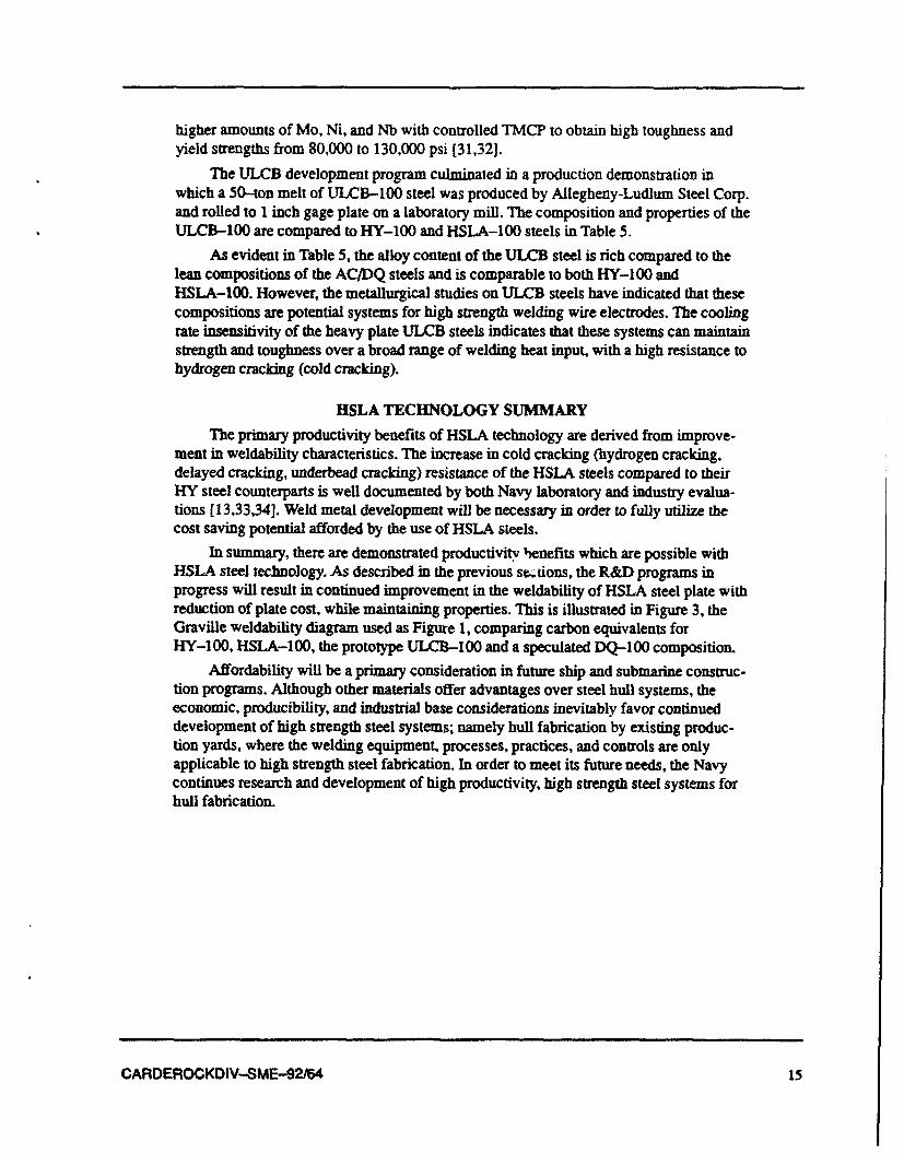
The ULCB development program culminated in a production demonstration inwhich a 50-ton melt of ULCB-100 steel was produced by Allegheny-Ludlum Steel Corp.and rolled to 1 inch gage plate on a laboratory mill. The composition and properties of theULCB-100 are compared to HY-100 and HSLA-100 steels in Table 5.
As evident in Table 5, the alloy content of the ULCB steel is rich compared to thelean compositions of the AC/DQ steels and is comparable to both HY-100 andHSLA-100. However, the metallurgical studies on ULCB steels have indicated that thesecompositions are potential systems for high strength welding wire electrodes. The coolingrate insensitivity of the heavy plate ULCB steels indicates that these systems can maintainstrength and toughness over a broad range of welding heat input, with a high resistance tohydrogen cracking (cold cracking).
HSLA TECHNOLOGY SUMMARY
The primary productivity benefits of HSLA technology are derived from improve-ment in weldability characteristics. The increase in cold cracking (hydrogen cracking,delayed cracking, underbead cracking) resistance of the HSLA steels compared to theirHY steel counterparts is well documented by both Navy laboratory and industry evalua-tions [13,33,34]. Weld metal development will be necessary in order to fully utilize thecost saving potential afforded by the use of HSLA steels.
In summary, there are demonstrated productivity henefits which are possible withHSLA steel technology. As described in the previous se..tions, the R&D programs inprogress will result in continued improvement in the weldability of HSLA steel plate withreduction of plate cost, while maintaining properties. This is illustrated in Figure 3, theGraville weldability diagram used as Figure 1, comparing carbon equivalents forHY-100, HSLA-100, the prototype ULCB-100 and a speculated DQ-100 composition.
Affordability will be a primary consideration in future ship and submarine construc-tion programs. Although other materials offer advantages over steel hull systems, theeconomic, producibility, and industrial base considerations inevitably favor continueddevelopment of high strength steel systems; namely hull fabrication by existing produc-tion yards, where the welding equipment, processes, practices, and controls are onlyapplicable to high strength steel fabrication. In order to meet its future needs, the Navycontinues research and development of high productivity, high strength steel systems forhull fabrication.
CARDEROCKDIV-SME-92/64 15
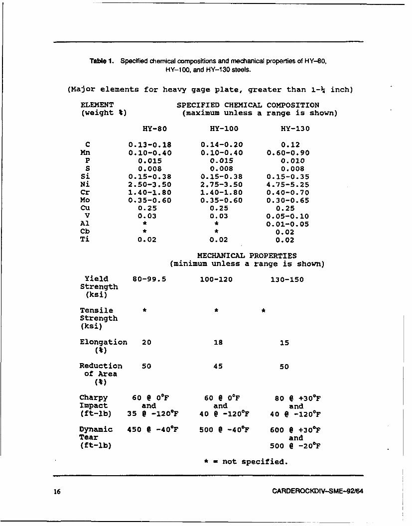
Table 1. Specified chemical compositions and mechanical properties of HY-80,
HY-1 00, and HY-1 30 steels.
(Major elements for heavy gage plate, greater than 1-¼ inch)
ELEMENT SPECIFIED CHEMICAL COMPOSITION(weight %) (maximum unless a range is shown)
HY-80 HY-100 HY-130
C 0.13-0.18 0.14-0.20 0.12Mn 0.10-0.40 0.10-0.40 0.60-0.90
P 0.015 0.015 0.010S 0.008 0.008 0.008
Si 0.15-0.38 0.15-0.38 0.15-0.35Ni 2.50-3.50 2.75-3.50 4.75-5.25Cr 1.40-1.80 1.40-1.80 0.40-0.70Mo 0.35-0.60 0.35-0.60 0.30-0.65Cu 0.25 0.25 0.25
V 0.03 0.03 0.05-0.10Al * * 0.01-0.05Cb * * 0.02Ti 0.02 0.02 0.02
MECHANICAL PROPERTIES(minimum unless a range is shown)
Yield 80-99.5 100-120 130-150Strength
(ksi)
Tensile * * *Strength(ksi)
Elongation 20 18 15(%)
Reduction 50 45 50of Area
(%)
Charpy 60 @ 0°F 60 6 0°F 80 @ +30*FImpact and and and(ft-lb) 35 @ -120°F 40 @ -120OF 40 @ -120OF
Dynamic 450 @ -40°F 500 @ -40°F 600 @ +300 FTear and(ft-lb) 500 @ -20OF
• - not specified.
16 CARDEROCKDIV-SME-92/64

Table 2. Spedfied chemical compositions and mechanical properties of HY-80, HSLA-80,HY-1 00, and HSLA-100 steels.
(Major elements for 1¼ inch gage plate)
ELEMENT SPECIFIED CHEMICAL COMPOSITION(weight %) (maximum unless a range is shown)
HY-80 HSLA-80 HY-100 HSLA-100MIL-S-16216K MIL-S-24645A MIL-S-16216K MIL-S-24546A
C 0.13-0.18 0.06 0.14-0.20 0.06Mn 0.10-0.40 0.40-0.70 0.10-0.40 0.75-1.15
P 0.015 0.020 0.015 0.020S 0.008 0.006 0.008 0.006
Si 0.15-0.38 0.40 0.15-0.38 0.40Ni 2.50-3.50 0.70-1.00 2.75-3.50 3.35-3.65Cr 1.40-1.80 0.60-0.90 1.40-1.80 0.45-0.75Mo 0.35-0.60 0.15-0.25 0.35-0.60 0.55-0.65Cu 0.25 1.00-1.30 0.25 1.45-1.75Cb * 0.02-0.06 * 0.02-0.06
V 0.03 0.03 0.03 0.03Ti 0.02 0.02 0.02 0.02
MECHANICAL PROPERTIES(minimum unless a range is shown)
Yield 80-99.5 80-100 100-120 100-125Strength
(ksi)
TensileStrength(ksi)
Elongation 20 20 18 18
Reduction 50 50 45 45of Area
(t)
Charpy 60 @ OF 60 @ -120OF 60 Q OF 80 @ 00FImpact and and and(ft-lb) 35 9 -120OF 40 @ -120°F 60 @ -120OF
Dynamic 450 @ -40OF * 500 @ -40F *Tear(ft-lb)
* -not specified.
CARDEROCKDIV-SME-92/64 17

Table 3. Chemical composition ranges for HSLA-80/100 steel plate.
ELEMENT SPECIFIED CHEMICAL COMPOSITION(weight %) (maximum unless a range is shown)
GRADE HSLA-80 HSLA-100
PLATE GAGE 1¼ all 1 all(inches) and less gages and less gages
(Presently specified in MIL-S-24645A, Amendment 1)
C 0.06 0.06 0.06 0.06Mn 0.40-0.70 0.85-1.15 0.75-1.15 0.75-1.05
P 0.020 0.020 0.020 0.020S 0.006 0.006 0.006 0.006
Si 0.40 0.40 0.40 0.40Ni 0.70-1.00 1.70-2.00 1.50-2.00 3.35-3.65Cr 0.60-0.90 0.45-0.75 0.45-0.75 0.45-0.75Mo 0.15-0.25 0.45-0.55 0.30-0.55 0.55-0.65Cu 1.00-1.30 1.00-1.30 1.00-1.30 1.45-1.75Cb 0.02-0.06 0.02-0.06 0.02-0.06 0.02-0.06
18 CARDEROCKDIV-SME-92/64

Table 4. Comparison of specified chemical compositions and mechanical properties of HY-100 andHSLA-1 00 steels to Grade 100 direct quenched (DO) production steel plate.
ELEMENT SPECIFIED CHEMICAL COMPOSITION(weight %) (maximum unless a range is shown)
Grade 100 (DQ) HY-100 HSLA-100(ladle composition) MIL-S-16216K MIL-S-24546A
C 0.04 0.14-0.20 0.06Mn 1.44 0.10-0.40 0.75-1.15
P 0.002 0.015 0.020S 0.001 0.008 0.006
S. 0.25 0.15-0.38 0.40Ni 0.73 2.75-3.50 3.35-3.65Cr 0.024 1.40-1.80 0.45-0.75Mo 0.16 0.35-0.60 0.55-0.65Cu 0.87 0.25 1.45-1.75CL 0.044 * 0.02-0.06
V 0.001 0.03 0.03Ti 0.015 0.02 0.02
N 0.003 * *
Heat Control Roll & DQ Hot Roll, Hot Roll,Treatment Temper Austenitize, Austenitize,
Water Quench, Water Quench,Temper Age Harden
MECHANICAL PROPERTIES(minimum unless a range is shown)
Yield 94 100-120 100-125Strength
(ksi)
Tensile 103 *Strength(ksi)
Elongation 30 18 18(M)
Reduction 74 45 45of Area
(%)
Charpy 112 @ 0°F 60 @ 0°F 80 @ 00FImpact and and(ft-lb) 40 @ -120OF 40 @ -120OF 60 @ -120OF
Dynamic 515 @ -40OF 500 @ -40OF *Tear(ft-lb)
• rinot specified.
CARDEROCKDIV-SME-92/64 19

Table5. Comparison ofspecified chemical compositions and mechanical properties of HY-100 andHSLA-100 steels to ULCB-100 production steel plate.
ELEMENT SPECIFIED CHEMICAL COMPOSITION(weight %) (maximum unless a range is shown)
ULCB-100 HY-100 HSLA-i00(ladle composition) MIL-S-16216K MIL-S-24546A
C 0.012 0.14-0.20 0.06Mn 1.04 0.10-0.40 0.75-1.15
P 0.005 0.015 0.020S 0.001 0.008 0.006
Si 0.34 0.15-0.38 0.40Ni 3.42 2.75-3.50 3.35-3.65Cr 0.31 1.40-1.80 0.45-0.75Mo 1.79 0.35-0.60 0.55-0.65Cu 0.06 0.25 1.45-1.75Cb 0.06 * 0.02-0.06
V nil 0.03 0.03Ti 0.004 0.02 0.02
Heat As Rolled, Hot Roll, Hot Roll,Treatment Temper Austenitize, Austenitize,
Water Quench, Water Quench,Temper Age Harden
MECHANICAL PROPERTIES(average) (minimum unless a range is shown)
Yield 96 100-120 100-125Strength
(ksi)
Tensile 104 *Strength(ksi)
Elongation 33 18 18(%)
Reduction 69 45 45of Area
(%)
Charpy 90 @ 0°F 6 0 @ 00 F 8 0 @ 0*FImpact and and(ft-lb) 40 @ -120OF 40 @ -120OF 60 @ -120°F
Dynamic 500 @ -40°F *Tear(ft-lb)
• = not specified.
20 CARDEROCKDIV-SME-92/64

C Mn P S Si Cr Ni Mo Cu Cb V B C.E."
TRADITIONALNAVY HY-80 ý15 .25 .01 .01 .25 1.40 2.70 .40 .05 - 01 - 0.78
STRUCTURALSTEELS HY-100 .17 .25 .01 .01 .25 1.40 2.90 .40 .05 - 01 - 0.81
CURRENTNAVY HSLA-80 .04 .55 .01 .005 .30 0.70 0.90 .20 1,20 04 - - 0.50HSLA
STEELS HSLA-100 .04 .90 .01 .005 .25 0.60 3.50 .60 1.60 .03 - - 0.81
"CE. - CARBON EQUIVALENT
CARBON EQUIVALENT
CE a C Mn+Si Ni+Cu Cr+Mo+V6+ + 5-- + 5
0.40HY-80 r13HY-100 0
HSLA-80 0 030HSLA-100 03ZONE III
ZONE 11 DIFFICULTz wWELDABLE TO9--zo 0.20
z0CD
0.10
ZOE
EASILY WELDABLEo0NE I
0.30 0.40 0.50 0.60 0.70 0.50
CARBON EQUIVALENT
Figure 1. Chemical compositions, carbon equivalents, and weldablity diagram forhigh strength naval steels.
CARDEROCKDIV-SME-92/64 21

ACR DOO
Arl--..
AC AC AC ___
TIME
CR: CONTROLLED ROLUNGo, TMR: THERMO-MECHANICAL ROLUNG,ACC: ACCELERATED COOUNG, DO: DIRECT QUENCHING. T: TEMPERING.AC: AIR COOLING
Figure 2. Schematic diagram of the temperature regimes for variations of TMCP of steels.
22 CARDEROCKDIV-SME-92164
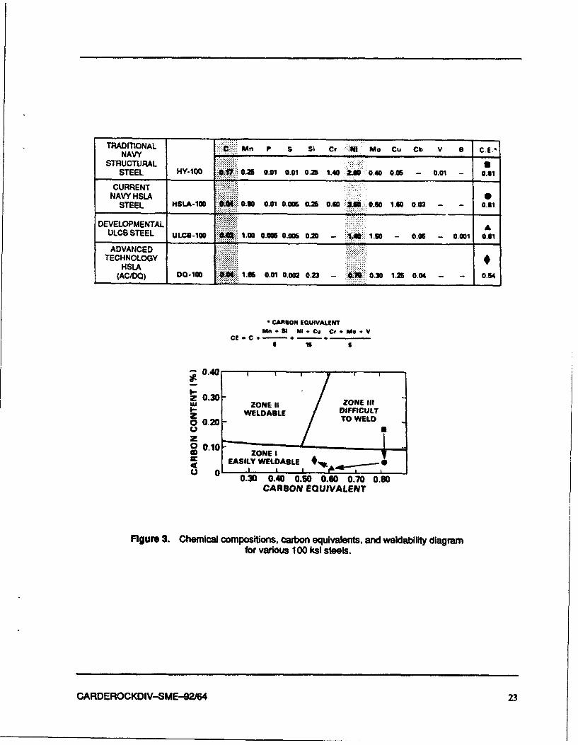
TRADITIONAL C Mn P S S1 C? N Mo Cu Cb V a .ENAVY
STRUCTURALSTEEL HY-1QW @W 0.25 0.01 0.01 0.35 .40 2.80 0.40 0.056 0.01 - 0.61
CURRENT
STEEL HSLA-100 M40.30 0.01 0.005 0.2S 0.0 3M 0.60 1.50 0.03 0 .61
DEVELOPMENTALULCB STEEL ULCO-100 ** 00 0.005 0.005 0.2 A-1.0 1.60 -0.05 -0.001 0.61
ADVANCEDTECHNOLOGY
HSLA(ACIDO) Do-1CO 1.06i 0.01 0,002 0.23-~ 03 . 00 0.54
CANNON EOUIVAIANT
CEC n + 3&4, NiI .CU Cr + Mo.I V
-0.40
z20.30-WZONE 11 ZONE fitzWELDABLE DIFFICULT
0.20 TO WELD
o 0.10-U ZONEI
EASILY WELDABLE*I L- i0 0.30 0.40 0.50 0.60 0.70 0.80
CARBON EQUIVALENT
Figure 3. Chemical compositions, carbon equivalents, and weidabilfty diagramfor various 100 ksi steels.
CARDEROCKDIV-SME-92164 23

REFERENCES
1. Palermo, P. M., "An Overview of Structural Integrity Technology," SNAME ShipStructure Symposium (Oct 1975).
2. Heller, S. R., Jr., "A Personal Philosophy of Structural Design of SubmarinePressure Hulls," Naval Engineers Journal, pp. 223-233 (May 1962).
3. Palermo, P. M., "A Designer's View of Welding Requirements of Advanced ShipStructures," Welding Journal, pp. 1039-1050 (Dec 1976).
4. Palermo, P. M., "Structural Integrity Criteria for Navy Hull Materials," NwvalEngineers Journal, pp. 73-86 (Oct 1976).
5. Heller, S. R., I. Fioriti, and J. Vasta, "An Evaluation of HY-80 Steel as a Struc-tural Material for Submarines (Part I)," Naval Engineers Journal, pp. 29-44(Feb 1965).
6. Heller, S. R., I. Fioriti, and J. Vasta, "An Evaluation of HY-80 Steel as a Struc-tural Material for Submarines (Part II)," Naval Engineers Journal, pp. 193-200(Apr 1965).
7. Stout, R.D. and W.D. Doty, Weldability of Steels, 3rd Ed., Welding ResearchCouncil, New York, NY (1978).
8. Miller, D. IL, "What Structural Engineers and Fabricators Need to Know AboutWeld Metal," The Welding Innovation Quarterly, vol. 5, no. 3, 1988, pp. 19-21.
9. Montemarano, T. W., B. P. Sack, J. P. Gudas, M. G. Vassilaros, and H. H. Vander-veldt, "High Strength Low Alloy Steels in Naval Construction," Journal of ShipProduction, vol. 2, no. 3 (Aug 1986).
10. Wilson, A.D.,"High Strength, Weldable Precipitation Aged Steels," Journal ofMetals, pp. 36-38 (Mar 1987).
11. Jesseman, R. J. and G. J. Murphy, "Mechanical Properties and PrecipitationHardening Response in ASTM A710 Grade A and A736 Alloy Steel Plates,"Journal of Heat Treating, vol. 3, no. 3, pp. 228-236 (June 1984).
12. Jesseman, R.J. and G.C. Schmid, "Submerged Arc Welding a Low Carbon, Cop-per Strengthened Alloy steel," Welding Journal Research Supplement, vol. 62,no. 11, pp. 321s-330s (Nov 1983).
13. Kvidahl, L. G., "An Improved High Yield Strength Steel for Shipbuilding,"Welding Journal, vol. 64, no. 7, pp. 42-48 (Jul 1985).
14. Rothwell, A. B., "Weldability of HSLA Structural Steels," Metals Progress (June1977).
15. Wilson, A. D., E. G. Hamburg, D. 1. Colvin, S. W. Thompson, and G. Krauss,"Properties and Microstructures of Copper-Precipitation Aged Plate Steels," Pro-ceedings of Microaioying'88, World Materials Congress, American Society forMetals, Metals Park, OH (Sep 1988).
CARDEROCKDIV-SME-92r64 25

16. Czyryca, E. J., R. E. Link, R. J. Wong, D. M. Aylor, T. W. Montemarano, and J. P.Gudas, "Development and Certification of HSLA-ICC Steel for Naval Ship Con-struction," Naval Engineers Journal, pp. 63-82 (May 1990).
17. Hamburg, E. G. and A. D. Wilson, "Production and Properties of Copper, AgeHardened Steels," Proceedings of International Symposium on Processing, Mi-crostructure and Properties of HSLA Steels, The Minerals, Metals, and MaterialsSociety, Warrendale, PA, pp. 241-260 (1988).
18. Gudas, J. P., R. B. Pond, and G. R. Irwin, "Metallurgical Aspectsof Plastic Fracture and Crack Arrest in Two High Strength Steels," NonlinearFracture Mechanics: Volume 11 - Elastic-Plastic Fracture, ASTM STP 995,American Society for Testing and Materials, Phila., PA, pp. 497-536 (1989).
19. DeArdo, A. J., "MTe Influence of Thermomechanical Processing and AcceleratedCooling on Ferrite Grain Refinement in Microalloyed Steels," Accelerated Cool-ing, P. D. Southwick (ed.) TMS-AIME, Pittsburgh, PA, pp. 97-119 (1986).
20. Tsao, Y. C., "Controlled Rolling and Accelerated Cooling of HSLA and MASteels," Chinese Journal of Metallurgical Science and Technology, vol. 3 (1987).
21. Honeycombe, R. W. K., Steels, Microsrructure, and Properties, Edward ArnoldPublishers, Ltd. (1981).
22. Tanaka, T., Tabata, N., Hatomura, T., and Shiga, C., "Three Stages of the Con-trolled Roiling Process," Microalloying '75, Proceedings of an InternationalSymposium on High-Strength, Low-Alloy Steels, pp. 107-119 (1977).
23. Tanaka, T., "Four Stages of the Thermomechanical Processing in HSLA Steels,"TMS-AIME Conference Proceedings on High Strength Low Alloy Steels, D. P.Dunne and T. Chandra (eds.).
24. Kozasu, I., "Overview of Accelerated Cooling of Plate," Accelerated Cooling ofSteel, P.D. Southwick (ed.), TMS-AIME, Pittsburgh, PA, pp. 15-31 (1985).
25. Ouchi, C., "Accelerated Cooling After Controlled Rolling in HSLA Steels,"TMS-AIME Conference Proceedings on High Strength Low Alloy Steels, D. P.Dunne and T. Chandra (eds.) (1984).
26. Bufalini, P., M. Pontremoli, M. Ghersi, A. Aprile, and C. Jannone, "Optimizingthe Microstructure and Strengthening Factors in High Strength Plates Producedby Accelerated Cooling," Accelerated Cooling of Steel, P. D. Southwick (ed.),TMS-AIME Pittsburgh, PA, pp. 387-400. (1986).
27. DeArdo, AJ., "Accelerated Cooling: A Physical Metallurgy Perspective," Cana-dian Metallurgical Quarterly, Vol.27, No.2, pp. 141-154 (1988).
28. Tanaka, J., et al., Transactions of the Iron and Steel Institute of Japan, Vol. 15,,pp. 19-26 (1975).
29. Nakasugi, H., et al., Alloys for the 80's, Climax Molybdenum Corp., pp.213-224 (1980).
26 CARDEROCKDIV-SME-92r64

30. Nakasugi, H., et al., Steel for Line Pipe and Pipeline Fittings, Metals Society,London, pp. 90-99 (1983).
31. Blicharski, M. R., C. I. Garcia, S. Pytel, and A. J. DeArdo, "Structure and Prop-erties of ULCB Plate Steels for Heavy Section Applications," Proceedings ofInternational Symposium on Processing, Microstructure and Properties of HSLASteels, The Minerals, Metals, and Materials Society, Warrendale, PA (1988).
32. Garcia, C. I. and A. J. DeArdo, "Structure and Properties of ULCB Platt Steelsfor Heavy Section Applications," Proceedings of Microalloying '88, World Mate-rials Congress, American Society for Metals, Metals Park, OH (Sep 1988).
33. Anderson, T. L., J. A. Hyatt and J. C West, "The Benefits of New High-StrengthLow-Alloy (HSLA) Steels," Welding Journal, pp. 21-26 (Sep 1987).
34. Lassaline, B., B. Zajackowski, and TM-. North, "Narrow Groove Twin WireGMAW of High-Strength Steel," Welding Journal, pp. 53-58 (Sep 1989).
CARDEROCKDIV-SME-92/64 27

THE DEVELOPMENT OF HIGH-STRENGTH, COOLING-RATE INSENSITIVE
Ultra-Low-Carbon Steel Weld Metals
M. G. Vassilaros and E. J. Czyryca
Naval Surface Warfare Center
Carderock DivisionAnnapolis Detachment - Metals & Welding
Annapolis, MD 21402-5067, USA
ABSTRACT
High-strength steel weld metal systems have been developed based on ultra-low car-bon bainitic (ULCB) metallurgy for systems in the range of 100,000 to 150,000 psi yieldstrength (690 to 1035 MPa). These weld metals show a potential for wire electrode for-mulations for HSLA steel welding with high productivity and affordability benefits infuture ship hull construction. The designs of these ULCB weld metal systems and proto-type welding electrodes use a bainitic metallurgy, where the as-deposited weld metalstrength is independent of weld metal cooling rate with a good low-temperature tough-ness derived through the ultra-low carbon levels. The cooling rate independence allowsthe use of a wide range of welding heat input levels, while the low carbon levels reducehydrogen-cracking sensitivity, eliminating the need for preheat and post-weld thermalsoaking. The elimination ofpreheat, expanded welding process operational envelope, andreduced post-weld cracking risk results in higher productivity, reduced labor require-mernts in both time and skill, and less intensive inspection provisions for high strengthsteel hull fabrication.
KEYWORDS: welding, metallurgy, high-strength steels, ULC8 steels, HY-80, HY-100,HSLA-80, HSLA-100.
CARDEROCKDIV-SME-92/64 29

INTRODUCTION
The welding of HY-80, HY-100, and HY-130, the high strength steels traditionallyused in U.S. Navy ship construction, requires a number of fabrication controls to preventweld cracking, which result in high fabrication costs. The Navy is conducting HSLA steelresearch and development programs with a goal of reducing shipbuilding costs, includingthe development of steel welding consumables for HSLA steel welding. This paper re-views the research conducted to develop a class of welding electrodes, based on ultra-lowcarbon, bainitic (ULCB) steels which demonstrate a potential for providing high strength,high toughness, and high quality weld metals for HSLA steel welding. The aim is to de-velop a steel welding system requiring less parameter control requirements andpreheat-free welding.
HSLA-80 steel was qualified for use in ship construction after an extensive pro-gram demonstrated that the low carbon, copper precipitation-strengthened steel met theperformance requirements of HY-80 steel, but was readily weldable without preheat[1,2]. Lower fabrication costs and higher productivity in construction were realized [3].Following the HSLA-40 program, an alloy development and qualification program wasconducted which resulted in HSLA-100 steel. HSLA-100 is also a low carbon, copperprecipitation strengthened steel, meeting the strength and toughness of HY-100 steel, butweldable with lower preheat [4].
The primary reason for preheat in the welding of the HY-series steels was to miti-gate underbead cracking (hydrogen related) in the hard, martensitic heat affected zone(HAZ). The HAZ of the very low carbon copper-strengthened HSLA-80 and HSLA-100steels typically does not harden, and HSLA-80 and HSLA-100 steel HAZ microstruc-tures are less sensitive to hydrogen cracking, and thus achieve excellent weldability. Thewelding and weldability testing demonstrated that HSLA-80 and HSLA-100 were signif-icantly more resistant to hydrogen cracking than HY-80 and HY-100, such as to allow arelaxation of preheat requirements. However, the weld metals were demonstrated to bethe "weak link" in the of the HSLA-100 base plate/weld metal system.
The welding consumables used for the qualification of HSLA-80 and HSLA-100were the same materials already qualified for HY-80 and HY-100 welding, respectively.No separate development of welding consumables for the HSLA steels was conducted.For HSLA-100, it was found that weld metals deposited by the flux-assisted welding pro-cesses (SMAW, FCAW, and SAW) were less resistant to hydrogen cracking than theGMAW process [4]. Reduction of welding preheat requirements was achieved for somewelding consumables, while other consumables such as the flux for SAW required a spe-cified maximum allowable moisture or hydrogen content before a reduction of weldingpreheat could be made. It was concluded that the welding process limitations forHSLA-100 were due to the welding consumables (developed for the HY-100 system)[4,5,6] and not the weldability of the plate. The lesson learned from the HSLA-1 00 quali-fication program, regarding the development of high-strength steel systems, was thatinitial focus must be on weld metal and welding product development, while plate devel-opment was the less difficult accomplishment.
The HSLA steel research and development program is investigating the thermo-mechanical, controlled-process (TMCP) and accelerated cooled/direct quenched (AC/DO) HSLA steels. AC/DQ processing involves on-line cooling, concurrent with plate
30 CARDEROCKDIV-SME-92/64

rolling, to take advantage of the conditioning of the high temperature phases of TMCPsteels. These modem HSLA steels use clean steelmaking practices, microalloying, andthermomechanical processing to retain a refined, stable, ductile, hydrogen-crack-resistantHAZ, suitable for high heat input welding. In the coming decades, ii can be anticipatedthat modular ship hull fabrication will continue using conventional metal-arc weldingprocesses. In order to gain higher productivity with these processes, weld metals must bedeveloped to allow the full benefit of these advantages.
In practice, shipyards can efficiently use steel systems which can weld plate gagesfrom 1/4 to 4 inches with a broad heat input range of 30 to 100 kW/inch, interpass temper-
atures of 3000 F, without deleterious effects to the weld metal. It is desirable to develop aless cooling rate sensitive weld metal deposit for welding the higher strength steels(above 690 MPa yield strength) to allow higher productivity with the conventional arcwelding processes.
HIGH-STRENGTH STEEL WELDING PRODUCTS
Welding consumables have a major impact on the welding costs incurred duringshipbuilding. The material cost of the consumables are not nearly as great as the costsassociated with using them in welding. These costs include the expense of preheat, elec-trode/flux conditioning and storage, high labor costs due to productivity limitations (heatinput and welding position restrictions), necessity for repair welding, and post-weld soak-ing to eliminate cracking, when required.
The objective in developing welding consumables for a given process is to econom-ically produce weldments that have properties at least as good as the base material.Typically, the as-deposited weld metal strength is required to be greater than the mini-mum required for the base metal, with the highest toughness that can be achieved.Economy demands that, in the construction of such a massive, complex structure as aship's hull, these properties be achieved "as welded." The difficulties in welding consum-ables development for high-strength steels lie in the following [7]:
(1) The welding process is an incremental melting and casting processwhich cannot benefit from the working and heat treatment used to obtainstrength, ductility, and toughness in wrought steel products;
(2) Because it is a casting, the weld metal will inevitably contain porosity,flaws, defects, etc., to some level which cannot be removed or repaired; and
(3) The arc welding processes involve many factors that directly influencethe properties of the weld metal, but cannot be measured or controlled to anaccurate or precise degree.
Welding involves a complex interplay of solid, liquid, gaseous, and plasma-statephenomena, such that research in welding encompasses many scientific disciplines. Muchof the research and development in welding equipment, electrodes, filler metals, fluxes,and shielding gases, has been conducted by the consumables manufacturers on an empiri-cal basis. New product developments have primarily been evolutionary, not innovative orthe result of new fundamental insights. The current electrodes designed for use with theHY-series, and employed for HSLA-801100, represent the most highly developed weld-ing consumables available from industrial research, with toughness superior to thoseproduced for the mass commercial market. The specified requirements for GMAW/SAW/
CARDEROCKDIV-SME-92/64 31

GTAW wire electrodes are given in Table 1. Weld metal development for higher strength(100 ksi and above) HSLA steels is necessary to fully utilize the cost saving potential ofHSLA steels. Exploratory development in high strength steel welding consumables is inprogress at Navy, university, and industrial laboratories [8].
WELD METAL PROPERTY REQUIREMENTS
The philosophy of requiring weld metal yield strength to overmatch plate yieldstrength for submarine structures was primarily based on explosion bulge testing of mildsteel weldments in the early 1950's. These experiments [9] showed that under dynamicplastic deformation, low strains developed in the weld metal versus the parent plate inproportion to the degree of overmatch in yield strength. Similar behavior was demon-strated in early HY-80 weldment explosion bulge tests. Since it was known that thefracture toughness and transition behavior of high strength weld metals was generallyinferior to that of the parent plate, the overmatching requirement was a concept for "pro-tecting" the weld metal [10].
Thus, for higher strength steels, the overmatch requirement is accompanied by adecrease in weld metal toughness and an increased propensity for weld metal cracking. Ingeneral, an increase in weld metal cooling rate (low heat input) is needed to increase yieldstrength to meet an "overmatching" strength requirement, and a decrease in toughnesstypically accompanies the increase in strength.
An increase in heat input and the concurrent increase in deposition rate reduces theoverall cost of welding steels. In addition, rework and repair costs might be improved,since joint deficiencies, such as lack of sidewall fusion and interbead fusion defects occurmore frequently when low heat inputs, to obtain a cooling rate to meet conditions forovermatching weld metal strength, are employed. Higher heat inputs promote better fu-sion characteristics, particularly in thinner section welding applications (less than 1 inchgage), where lower heat inputs are specified in order to meet minimum mechanical prop-erty requirements.
ULCB STEEL PLATE DEVELOPMENTThe ULCB steels were a result of research in the late 1960's, where steels with low
carbon levels, 0.03 to 0.095%, were heat treated to produce lower bainite or acicular fer-rite. The steels had yield strengths in the range of 40,000 to 80,000 psi and showedsuperior impact toughness with very low toughness transition temperature. Ford ResearchLaboratory produced a ULCB steel with the following composition: 0.03 C, 3 Mo, 3 Ni,0.7 Mn, 0.3 Si, 0.5 Nb, which had a 130,000 psi yield strength and excellent low-temper-ature impact toughness in hot-rolled, air cooled plate. However, due to the high Ni + Mocontent, the alloy was very expensive and the ultra-low carbon content was difficult forsteel mills of that era to produce.
The ultra-low carbon rendered the ULCB steel resistant to cold cracking for goodweldability. Alloy design for high toughness, weldable steels for high-strength pipelinesby the Climax Molybdenum Laboratory resulted in a low-carbon, Mn-Mo-Nb steel sys-tem which showed that: (1) reducing the carbon reduced the toughness transitiontemperature with an optimum carbon content between 0.002% and 0.05%, and (2) for
32 CARDEROCKDIV-SME-92164

alloys with less than 0.05% carbon, additions of up to 2% manganese continued to in-crease strength and lower the fracture transition temperature.
The Navy program on ULCB steels initiated with studies of ULCB plate steels. Fea-sibility was demonstrated for developing an air-cooled, 100,000 psi yield strength ULCBsteel with high toughness in plate and HAZ. A experimental family of ULCB steels wasdemonstrated on a laboratory scale that used higher amounts of Mo, Ni, and Nb with con-trolled TMCP to obtain high toughness and yield strengths from 80,000 to 130,000 psi[11, 12]. The most important metallurgical aspects of the ULCB plate studies were thatthe bainitic steels were cooling-rate independent, i.e. properties in the plates were inde-pendent of plate thickness. Also, the strength levels were directly related to composition,which could be formulated by simple formulae.
In the final stage of ULCB development program, a production demonstration,50-ton melt of ULCB-100 steel was produced and rolled to 1-inch gage plate on a labo-ratory mill. The composition and properties of the ULCB-100 are compared to HY-100and HSLA-100 steels in Table 2. As shown, the alloy content of the ULCB-100 steel wascomparable to both HY-100 and HSLA-100 in total alloy content.
However, the metallurgical research on ULCB steels indicated that these composi-tions are potential systems for high strength welding wire electrodes. The cooling rateinsensitivity of the heavy plate ULCB steels showed that the ULCB systems can maintainstrength and toughness over a broad range of welding heat input, with a high resistance tohydrogen cracking (cold cracking).
ULCB WELDING ELECTRODE DEVELOPMENTThe cooling-rate insensitive bainitic microstructure of the ULCB plate steel studies,
the 0.02C-Mn-Ni-Mo-Nb system, provided a basis for weld metal system with the fol-lowing features:
Weld metal deposits with cooling-rate insensitive, bainitic microstucturesfor consistent strength under all welding process parameters;Ultra-low carbon for hydrogen-cracking (cold cracking) resistance and hightoughness; andFine, stable inclusions for grain size control during weld metal solidificationand during multipass welding.
The alloy development research initially used GTAW of ULCB plate with deep V-grooves with matching composition electrode to determine the effects of alloying onstrength, cooling rate sensitivity, and impact toughness. The results were then used toguide the optimization of the system to indicate compositions for melts of ULCB steels tobe drawn to wire electrode for GMAW.
Approximately 45 composition variations within the 0.02C-Mn-Ni-Mo-Nb systemwere included in the initial study. The GTAW deposits in the groove were machines toprovide samples for tensile and Charpy V-notch impact tests. The results of these testsindicated the following*
Yield and tensile strength was dependent on composition by a complexfunction of all the alloying elements, not solely a function of carbon content(0'.015 to 0.030%);
CARDEROCKDIV-SME-92164 33

High Ni content can increase strength, but reaches a maximum effectivenessat 3.5 Ni with high molybdenum content (3.5 Mo);
Ni content greater than 3.5% continues to increase strength when Mo isgreater than 2.5%;Manganese demonstrated a greater than predicted effect in strength in-crease, but appeared to have a maximum effect at 1.5 Mn in deposits with3.5% Mo;
The effect of Mo content on strength was less than predicted and the effectwas further diminished at high Mn content;
Nb content up to 0.05% had a strong effect on strength.
The results of the ULCB composition studies are summarized in Table 3, which showsthe effectiveness of each alloying element on yield strength increase (in ksi per % alloy)for two welding conditions; 60 and 120 kI/inch average heat input (approximately 2.5and 5 kJ/mm). These are compared to predicted effectiveness of alloying elements(strength vectors) for alloy steel plate design [13].
Figure I illustrates the results of all-weld-metal tensile tests of one of the exper-imental ULCB-100 GTAW series of the following composition:
0.018 C / 1.40 Mn / 3.48 Ni / 3.50 Mo / 0.059 Nb
In Figure 1, the results for the ULCB weld metal are compared to those forMIL.-120S GMAW weld metal properties over the same range of high heat inputs. Ofnote is the demonstration of the insensitivity of the ULCB weld metal strength to coolingrate (welding heat input). The effect of multipass welding on the ULCB weld metalstrength was simulated by the "Gleeble" apparatus, which imposes a programmed ther-mal cycle on a metal sample by controlled resistance heating. In these tests, an all-weldmetal sample of the ULCB deposit was subjected to one or more time/temperature cyclesrepresenting multiple passes deposited under the same welding parameters as the initialweld. Tensile tests were conducted after the multipass simulation. Figure 2 shows the re-sults for two of the compositions, including the weld metal used in Figure 1. In all casesthe weld metal strength remained stable or slightly increased.
It is well known that carbon content, grain size, and inclusions are significant metal-lurgical factors controlling the toughness of steels; both transition temperature and uppershelf toughness. Figure 3 shows Charpy V-notch impact toughness results for several ofthe ULCB GTAW weld metal deposits. In only a few cases did the toughness exceed thegoal of 60 ft-lb at 0- F and 45 ft-lb at --60* F. In most cases, the reduced low-temperaturetoughness was due to coarse MnS or oxides in the deposit. Although the experimentalmelts were vacuum induction melted, inclusions in the original plates persisted in theGTAW remelting and deposition.
Studies in progress to produce ULCB wire electrode for GMAW used vacuum arcremelting (VAR) for improved cleanliness for reducing the effects of coarse inclusions onweld metal toughness. Included in the continuing program are studies of the effects ofmicroalloying to promote small, uniform distributions of inclusions for grain size control(toughness increase), and the effects of shielding gas composition on the transfer of reac-tive elements in the ULCB wire into the weld deposit. The compositions selected for theVAR melts, based on statistical analysis of the GTAW weld deposit results were varia-
34 CARDEROCKDIV-SME-92/64

tions of the following system: C - 2 Mn - 3 Mo - 5 Ni. The composition of melts for theoptimization of toughness were as follows:
Effect of Carbon Content
0.02 C- 2 Mn-3 Mo-5 Ni
0.04 C-2 Mn- 3 Mo-5 Ni
0.06 C-2 Mn- 3 Mo-5 Ni
Effect of Microalloy Inclus" ns
0.02 C- 2 Mn - 2.5 Mo -5 Ni - 0.006 N - 0.010 Ti
0.02 C -2 Mr - 2.5 Mo-5 Ni - 0.006 N - 0.018 Ti0.02 C - 2 Mn - 2.5 Mo - 5 Ni - 0.006 N - 0.022 Ti
These ULCB steel ingots wcre sawcut and surface conditioned were rolled to rod for wiredrawing. The rods were progressively drawn, stress relieved, cleaned, and coiled forGMAW 1/16-inch diameter wire electrode.
SUMMARY
High-strength steel weld metal systems have b-en developed based on ultra-lowcarbon bainitic (ULCB) steel metollurgy. The designs of these ULCB weld metal systemsand prototype welding electrndes use a bainitic metallurgy, where the as-deposited weldmetal strength is independent of weld metal cooling rate, stable for multipas welding.Good low-temperature toughness was derived through the ultra-low carbon levels andfine microalloy inclusions to control grain size. The cooling rate independence allows theuse of a wide range of welding heat input levels, while the low carbon levels reduce hy-drogen-cracking sensitivity, eliminating the need for preheat and post weld thermalsoaking.
CARDEROCKDIV-SME-92/64 35

Table 1. Specified chemical compositions and mechanical properties for GMAW/SAW/GTAW wire
electrodes, MIL-XXXS type, for welding the HY-series steels.
ELECTRODESPECIFICATIONMIL-E- 23765/2D 23765/2D 24355B
ELECTRODETYPE MIL- 100S-1 120S-1 140S-1
FOR WELDING HY-80 HY-100 HY-130
ELEMENT SPECIFIED CHEMICAL COMPOSITION(weight %) (maximum unless a range is shown)
C 0.08 0.09 0.12Mn 1.25-1.80 0.90-2.35 1.50-2.00
P 0.012 0.012 0.010S 0.008 0.008 0.010
Si 0.20-0.55 0.60 0.30-0.50Ni 1.40-2.10 1.00-3.00 1.95-3.10Cr 0.30 0.80 0.65-1.05Mo 0.25-0.55 0.30-1.00 0.40-1.00Cu . * 0.15
V 0.05 0.03 0.04Al 0.10 0.10 0.04Zr 0.10 0.10 0.04Ti 0.10 0.10 0.04
WELD METAL MECHANICAL PROPERTIES(minimum unless a range is shown)
Yield 82-110 102-122 135-150Strength
(ksi)
Tensile * * *
Strength(ksi)
Elongation 16 14 14(%)
Charpy 60 @ 0°F 60 @ 0°F *
Impact and and(ft-lb) 35 @ -60 0F 45 @ -600F
Dynamic 450 @ +30 0 F 575 @ +300F 475 @ +30°FTear and and(ft-lb) 300 @ -20OF 400 @ -20'7
* = not specified.
36 CARDEROCKDIV-SME-92/64

Table 2. Comparison of specified chemical compositions and mechanical properties of HY-100 andHSLA-1 00 steels to ULCB-1 00 production steel plate.
ELEMENT SPECIFIED CHEMICAL COMPOSITION(weight %) (maximum unless a range is shown)
ULCB-100 HY-100 HSLA-100(ladle composition) MIL-S-16216K MIL-S-24546A
C 0.012 0.14-0.20 0.06Mn 1.04 0.10-0.40 0.75-1.15
P 0.005 0.015 0.020S 0.001 0.008 0.006
Si 0.34 0.15-0.38 0.40Ni 3.42 2.75-3.50 3.35-3.65Cr 0.31 1.40-1.80 0.45-0.75Mo 1.79 0.35-0.60 0.55-0.65Cu 0.06 0.25 1.45-1.75Cb 0.06 * 0.02-0.06
V nil 0.03 0.03Ti 0.004 0.02 0.02
Heat As Rolled, Hot Roll, Hot Roll,Treatment Temper Austenitize, Austenitize,
Water Quench, Water Quench,Temper Age Harden
MECHANICAL PROPERTIES(average) (minimum unless a range is shown)
Yield 96 100-120 100-125Strength
(ksi)
Tensile 104 * •Strength(ksi)
Elongation 33 18 18(%)Reduction 69 45 45of Area
(%)
Charpy 90 @ OF 6 0 @ 0*F 80 @ 00FImpact and and(ft-lb) 40 @ -120OF 40 0 -120@F 60 @ -120OF
Dynamic 500 @ -40 0 F *Tear(ft-lb)
* - not specified.
CARDEROCKDIV-SME-92/64 37

Table 3. Change in yield strength (ksi) per % alloying element forexperimental ULCB steels.
Allay < 3.5% Ni > 3.5 %Ni Moly I Cubam < 1.5% Win > 1 ,5% Mn < 0.45% Nb > 0A45 Nb
Hen inpat 60 120 60 120 60 120 60 120 60 120 60 220 60 120 60 120II I I
2.5% Me 6.25 4.17 -2.3 -1.1 - - 76.9 230 22.5 18.4 261 130
3.5% Mo 4.52 9.03 4.52 9.03 - - 175 625 30.6 21.3 1.3 -1.3 267 133 467 333
2.5% Ni - - - - 4.72 4.72
3 ,5 % N ii .- 1 .0 2 .0 1 4 0 7 0
2.0% Mr -3.1 -2.1 . .--
Heucimkd 3.9 3.9 3.9 3.9 17.6 17.6 115 115 15.3 15.3 15.3 15.3 - - - -
Picketig 11 . 1.1 1.1 1.1 174 174 247 247 12.0 120 12.0 12.0 168 268 168 168
ULCB-1 00 AUTOGENOUS GTAW WELD METAL140 MIL-120S GMAW YS
120- 0 -O6
=100-
zc s80- ULCB Y
60- o 0.2% YIELD ST.0 ULTIMATE TENSILE STA LINDE 120 GMA YIELD4 40 1 1 1 . .. 1 . . 1 1
5 10 15 20 25 30 35 40 45 50 55 60 65 70 75COOLING RATE AT 10000F
105 75 40HEAT INPUT, kJ/ln.
Figure 1. Strength of as-deposited ULCB weld metal versus cooling rate (welding heat input).
38 CARDEROCKDIV-SME-92/64

Yield Strength (Ksl)
140
130-
120-
110-
100-
go0 Flat Tensile*B-As Welded -*- Single cycle
so00 60 120 180
Heat Input
Figure 2a. Effect of simulated muttipass welding thermal cycles on ULOB weld metal yield strength.0.02 c - 1.5 Mn-4.5 Ni
Yield Strength (Ksl)140 -
130
120
110
100
90FltTnie
0 60 120 180Heat Input
Figure 2b. Effect of simulated mufllias welding thermal cycles on ULOB weld metal yield strength.0.02 c - 1.5 Mn - 3.5 Mo - 4.0 NI
CARDEROCKDIV-SME-92/64 39

CVN Energy FT-LB % SHEAR200
180 - 100
A 90160 0 -80
140 02 0 70
120 0SA 60
100 x 0
80 0 40
60- A 300 .03C-1.Sn-2.5Mo-3.5Ni
40 X .o2C--•.Sn-2.SMo-4.sNj" 20
20 X .oAc-1.S•n-2.5Mo-2.SNi 10
0 " 0-78 -50 -25 0 25 50 75
Temperature F
Figure 3. Charpy V-notch impact energy for ULCB weld metals.(60 to 100 kJ/inch)
40 CARDEROCKDIV-SME-92r64

REFERENCES
1. Montemarano, T.W., B.E Sack, J.P. Gudas, M.G. Vassilaros, and H.H. Vander-veldt, "High Strength Low Alloy Steels in Naval Construction," Journal of ShipProduction, vol. 2, no. 3, pp. 145-16 (August 1986).
2. Czyryca, EJ., "Development, Qualification, and Certification of HSLA-80 andHSLA-100 Steels for U. S. Navy Ship Construction,"The Metallurgy, Welding,and Qualification of Microalloyed (HSLA) Steel Weldments, Proceedings of theInternational Conference, Houston, TX, Nov. 6-8. 1990, American Welding So-ciety, Miami, FL (1991).
3. Kvidahl, L.G., "An Improved High Yield Strength Steel for Shipbuilding," Weld-ing Journal, vol. 64, no. 7, pp. 42-48 (July 1985).
4. Czyryca, EJ., R.E. Link, RJ. Wong, D.M. Aylor, T.W.Montemarano, and J P.Gudas, "Development and Certification of HSLA-100 Steel for Naval Ship Con-struction," Naval Engineers Journal, pp. 63-82 (May 1990).
5. Holsberg, P.W. and RJ. Wong, "Welding of HSLA-100 Steel for Naval Applica-tions," Weldability of Materials, ASM International, Materials Park, OH, pp.219-239 (1990).
6. Heid, R. and T. Wallace, "Weldability Testing and Qualificationof HSLA-100,"The Metallurgy, Welding, and Qualification of Microalloyed (HSLA) Steel Weld-ments, Proceedings of the International Conference, Houston, TX, Nov. 6-8,1990, American Welding Society, Miami, FL (1991).
7. Heller, S.R., Jr., "The Use of Quenched and Tempered Steels for Welded PressureVessels," Naval Engineers Journal, pp. 709-723 (Oct 1967).
8. Olson, D.L and T.A. Siewert, "Present Consumable Technology Advances intothe 21st Century," Welding Journal, pp. 37-40 (Nov 1990).
9. Pellini, W.S. and C.E. Hartbower, "Investigation of the Factors Which Determinethe Performance of Weldments," Welding Journal (Oct 1951).
10. "Effective Use of Weld Metal Yield Strength for HY-Steels," National MaterialsAdvisory Board, National Research Council, Report No. NMAB-380 (Jan 1983).
11. Blicharski, M.R., C.I. Garcia, S. Pytel, and AJ. DeArdo,"Structure and Proper-ties of ULCB Plate Steels for Heavy Section Applications," Proceedings ofInternational Symposium on Processing, Microstructure and Properties of HSLASteels, The Minerals, Metals, and Materials Society, Warrendale, PA (1988).
12. Garcia, Ci., and AJ. DeArdo, "Structure and Properties of ULCB Plate Steelsfor Heavy Section Applications," Proceedings of Microalloying '88, World Mate-rials Congress, American Society for Metals, Metals Park, OH (Sep 1988).
13. Pickering, F.B., Physical Metallurgy and the Design of Steels, Applied SciencePublishers, Ltd., London (1978).
CARDEROCKDIV-SME-92(64 41

INITIAL DISTRIBUTION
Copies CENTER DISTRIBUTION
I OCNR Copies Code Name
1 0225 2 0115
1 4325 1 17
I Library 1 1720
1 NAVPGSCOL 1 1720.13 172.4
1 USNROTCHU& 3 1730
NAVADMINU MIT 2 1730.3
4 NRL 1 1740
1 Code 6320 1 1740.1
1 Code 6320.1 1 1740.3
1 Code 6323 1 1740.4
1 Code 6324 1 281 2801
15 NAVSEA 1 2801
1 SEA 05M 1 2809
3 SEA 05M2 1 281
1 SEA 05P 1 281s
I SEA 05P1 1 2810.1
1 SEA 05P2 1 2812
1 SEA 05P2(DCN) 1 2812 ALM
1 SEA 05P3 1 2813
1 SEA 05P4 5 2814
1 SEA 05P4(JAM) 15 2814 ETC
1 SEA 92R 1 2814 EMF
I SEA08S 1 2814 LIL
1 SEA 350XT (Evans) 1 2814 UEL
1 2814 MEM
I PMS 393T 1 2814 WCP
1 2814 RLT
2 DTIC 1 2815
CARDEROCKDIV-SME-92r64 43

CENTER DISTRIBUTION
Copies Code Name
1 2815 JJD
1 2815 RJW
1 2815 GLF5 2815 MGV
1 2831 2842 34212 3422
44 CARDEROCKDIV-SME-92/4

REPORT DOCUMENTATION PAGE IMBNo._0704-018PIAC pof h~enb'1w da~ono~*.Vm is .. nabft0 a~wr I how~.pW1rPW.*u ,d& W& f I refite v Mons. sad*U data WMft.. qA~rWVQ AWd
flm1•w li b*t needed, ud cam~iriiean md,wdeIs. •le cccon alhU~maot• Sav cnwun tagwdnw r w b urWd eamnae t' vr• 0n1ow aaV.ct of 1w• md• olhtmJ•*nabtn.b~ldnd a~gealovw lorerd.~g 9,s bue. 0 WenPr~o~n Heqar.ivw Senvea. O~wc~ata A" h~m~a•i C•ao ww Rao•a 121 .MPF• Oai~a Petiwey. * 1204 A*WOnp.
VA 22202-43W0. aw 0*. ofee a &e PaAenduv* Rtouctam PrMt (0704.015%, Wi•MV•ng•. DC 2W013
1. AGENCY USE ONLY (Leave blank) 2. REPORT DATE 3. REPORT TYPE AND DATES COVERED
I April 1993 Research & Development4. TITLE AND SUBTITLE 5, FUNDING NUMBERS
Advances in Low Carbon, High Strength Ferrous Alloys62234N, RS34S55
6. AUTHOR(S)
EJ. Czyryca and M.G. Vassilaros
"7. PERFORMING ORGANIZATION NAME(S) AND ADDRESS(ES) 8. PERFORMING ORGANIZATION
REPORT NUMBER
Carderock DivisionNaval Surface Warfare Center CDNSWC/SME-92/64Bethesda, MD 20084-5000
9. SPONSORING /MONITORING AGENCY NAME(S) AND ADDRESS(ES) 10. SPONSORING /MONITORINGAGENCY REPORT NUMBER
11. SUPPLEMENTARY NOTES
12a. DISTRIBUTION /AVAILABILITY STATEMENT 12b. DISTRIBUTION CODE
Approved for public release; distribution is unlimited.
13. ABSTRACT (Maximum 200 won*s)
Carderock Division, Naval Surface Warfare Center participated in the Indo-US Pacific Rim Workshop on"Advances in Low Carbon, High Strength Ferrous Alloys" held in New Delhi, India, 25 to 28 March 1992. E.J.Czyryca and M.G. Vassilaros gave invited presentations on the status of Navy programs on steel plate and weldmetal research and development, respectively. The workshop was jointly sponsored by Office of Naval Research,Naval Research Laboratory, US Army Research Office - Far East, and the National Metallurgical Laboratory ofIndia.
This report contains papers based on the two presentations. Paper 1 - "Advances in High Strength Steel Tech-nology for Naval Hull Construction," by EJ. Czyryca, was presented by Mr. Czyryca. It covers an overview of USNavy steel plate research programs. Paper 2- "The Development of High-Strength, Cooling-Rate Insensitive U1-ira-Low-Carbon Weld Metals," by M.G. Vassilaros and EJ. Czyryca, was presented by Dr. Vassilaros. It presentsthe status of research in high-strength steel weld metal systems based on ultra-low carbon bainitic (ULCB) metal-lurgy. ULCE weld metals show a potential for wire electrode formulations for HSLA steel welding, where the as-deposited weld metal strength is independent of weld metal cooling rate with a good low-temperature toughness.
14. SUBJECT TERMS 15. NUMBER OF PAGESMetallurgy, High-strength steels, Welding, HY-80, HY-100, HY-130, HSLA-100,Mechanical properties 16. PRICE CODE
17. SECURITY CLASSIFICATION 18. SECURITY CLASSIFICATION 19. SECURITY CLASSIFICATION 20. LIMITATION OF ABSTRACT
OF REPORT OF THIS PAGE OF ABSTRACT
UNCLASSIFIED UNCLASSlFJED UNCLASSIFIEDNSN 7540101-280-5500 St ndara •-orm 291 ýpev. 2-89j