carbonaceousanode materials and conductiveadditives as key...
TRANSCRIPT

Carbonaceous Anode Materials and Conductive Additives
as Key To Higher Performance Lithium-ion Batteries
7th International Automotive Battery Conference Europe
31 January 2017
Michael E. Spahr
Technology Cluster Director, Energy & Electronic Materials
IMERYS Innovation, Bodio TI, Switzerland
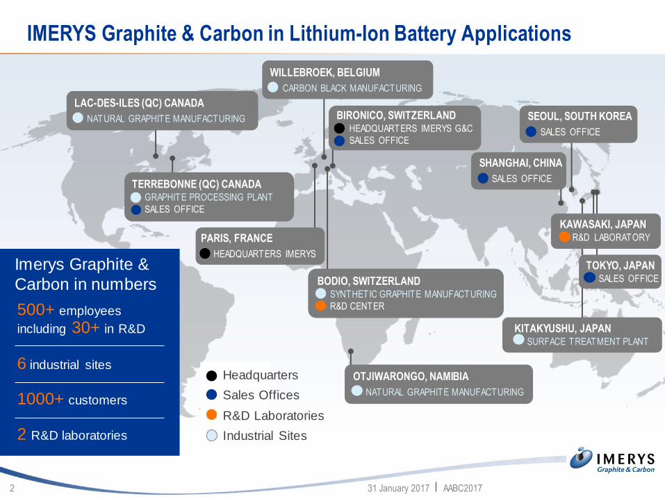
IMERYS Graphite & Carbon in Lithium-Ion Battery Applications
31 January 2017 AABC20172
Imerys Graphite &
Carbon in numbers
500+ employees
including 30+ in R&D
6 industrial sites
1000+ customers
2 R&D laboratories
LAC-DES-ILES (QC) CANADA
NATURAL GRAPHITE MANUFACTURING
TERREBONNE (QC) CANADA GRAPHITE PROCESSING PLANT
SALES OFFICE
PARIS, FRANCE
HEADQUARTERS IMERYS
BIRONICO, SWITZERLANDHEADQUARTERS IMERYS G&C
SALES OFFICE
BODIO, SWITZERLANDSYNTHETIC GRAPHITE MANUFACTURING
R&D CENTER
WILLEBROEK, BELGIUM
CARBON BLACK MANUFACTURING
SEOUL, SOUTH KOREA
SALES OFFICE
SHANGHAI, CHINA
SALES OFFICE
Headquarters
Sales Offices
R&D Laboratories
Industrial Sites
OTJIWARONGO, NAMIBIA
NATURAL GRAPHITE MANUFACTURING
KAWASAKI, JAPANR&D LABORATORY
TOKYO, JAPANSALES OFFICE
KITAKYUSHU, JAPANSURFACE TREATMENT PLANT
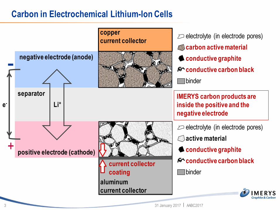
Carbon in Electrochemical Lithium-Ion Cells
31 January 2017 AABC20173
Li+
negative electrode (anode)
positive electrode (cathode)
e-
separator IMERYS carbon products are
inside the positive and the
negative electrode
electrolyte (in electrode pores)
carbon active material
conductive graphite
conductive carbon black
binder
electrolyte (in electrode pores)
active material
conductive graphite
conductive carbon black
binder
copper
current collector
aluminum
current collector
current collector
coating
+
-

Carbonaceous Anode Materials and Conductive Additives as Key To
Higher Performance Lithium-ion Batteries
Carbon conductive additives for the positive electrode
Carbon conductive additives for the negative electrode
Electrochemically active carbon materials
Carbon/silicon composites
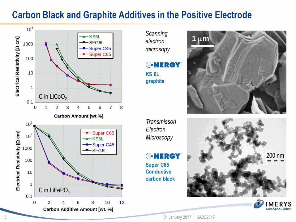
Carbon Black and Graphite Additives in the Positive Electrode
31 January 2017 AABC20175
0.1
1
10
100
1000
104
0 1 2 3 4 5 6 7 8
KS6L
SFG6L
Super C45
Super C65
Ele
ctr
ica
l R
es
isti
vit
y [
cm
]
Carbon Amount [wt.%]
0.1
1
10
100
1000
104
105
0 2 4 6 8 10 12
Super C65
KS6L
Super C45
SFG6L
Ele
ctr
ica
l R
es
isti
vit
y [
cm
]
Carbon Additive Amount [wt. %]
200nm 100000 : 1
TEM-Abbildung
Probenbezeichnung:
Super P Li
Datenträgerkennung: TEM_DB3_595XV847_0_0
Bildnummer: 32847
19517
Auftrags-Nr.: A060024276
Bearbeiter: Klehm
Präparation:
Isoprop./Wasser disp.aufgetr.
200 nm
C in LiCoO2
C in LiFePO4
Scanning
electron
microsopy
Transmisson
Electron
Microscopy
Super C65
Conductive
carbon black
KS 6L
graphite
1 mm
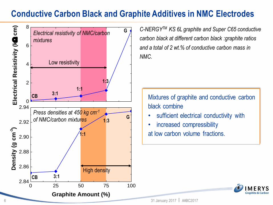
Conductive Carbon Black and Graphite Additives in NMC Electrodes
31 January 2017 AABC20176
Low resistivity
High density
1:3
1:13:1
CB
G
1:3
1:1
3:1CB
G
C-NERGYTM KS 6L graphite and Super C65 conductive
carbon black at different carbon black :graphite ratios
and a total of 2 wt.% of conductive carbon mass in
NMC.
Press densities at 450 kg cm-1
of NMC/carbon mixtures
Electrical resistivity of NMC/carbon
mixtures
Mixtures of graphite and conductive carbon
black combine
• sufficient electrical conductivity with
• increased compressibility
at low carbon volume fractions.
0 25 50 75 1002.84
2.86
2.88
2.90
2.92
2.94
De
ns
ity
(g
cm
-3)
Graphite Amount (%)
0
2
4
6
8
Ele
ctr
ica
l R
es
isti
vit
y (
k
cm
)

Graphite as Compaction Aid in the Conductive Electrode Mass
31 January 2017 AABC20177
*NMC electrodes with 4 wt.% carbon conductive mass/5 wt.% PVDF binder material
1C/1D, 1 M LiPF6 in EC/EMC 1:3 (w/w)
0 20 40 60 800
20
40
60
80
100
120
140
160
180
Super C65
Super C65/KS 6L (1:1 wt.)
Sp
ec
ific
Ch
arg
e (
mA
h g
-1)
Cycle Number
The graphite additive improves the electrode
compressibility and charge density*
0 20 40 60 800
50
100
150
200
250
300
350
400
Ch
arg
e D
en
sit
y (
mA
h L
-1)
Cycle Number
Super C65
Super C65/KS 6L (1:1 wt.)
Similar electrode resistivity leads to a similar
specific charge of the electrode*

Adhesion of NMC Electrodes
31 January 2017 AABC20178
Mixed conductive graphite/carbon black masses show better adhesion of the
electrode on the current collector foil than pure conductive carbon black.

Graphite Additives in the Negative Electrode
31 January 2017 AABC20179
Density of C-NERGYTM ACTILION 1 electrodes
containing C-NERGYTM SFG 15L
5 mm
SFG 15L
graphite
0 50 100 1501.3
1.4
1.5
1.6
1.7
1.8
2 % SFG 15L
5 % SFG 15L
8 % SFG 15L
Ele
ctr
od
e D
en
sit
y (
g c
m-3
)
Press Force (kN cm-2)
Binder material: 1.5 wt.% SBR/1.5 wt.% CMC
Influence of C-NERGYTM SFG 15L on the cycling
stability of C-NERGYTM ACTILION 1 electrodes
0 10 20 30 40 50300
320
340
360
380
400
Sp
ec
ific
Ch
arg
e (
mA
h g
-1)
Cycle Number
0 % SFG 15 L
10 % SFG 15 L
Lithium half-cells, 1C/3D (CCCV)
Binder material: 1.5 wt.% SBR/1.5 wt.% CMC
Electrode density: 1.7 g cm-3
Electrolyte: 1 M LiPF6 in EC/EMC 1:3 (w/w)
Graphite Additives in the Negative Electrode
31 January 2017 AABC201710
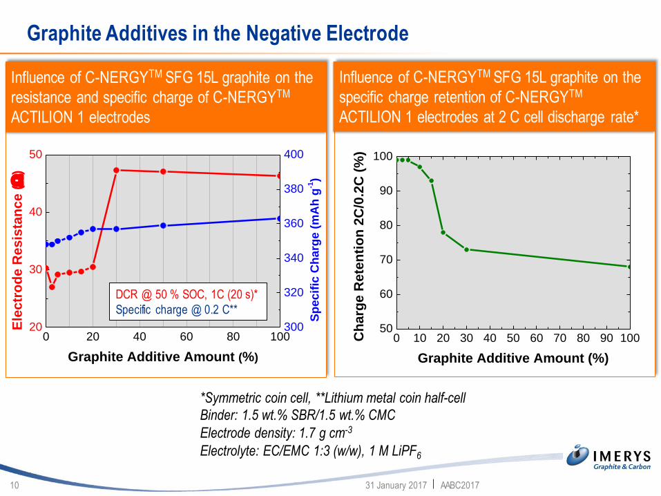
*Symmetric coin cell, **Lithium metal coin half-cell
Binder: 1.5 wt.% SBR/1.5 wt.% CMC
Electrode density: 1.7 g cm-3
Electrolyte: EC/EMC 1:3 (w/w), 1 M LiPF6
Influence of C-NERGYTM SFG 15L graphite on the
resistance and specific charge of C-NERGYTM
ACTILION 1 electrodes
0 20 40 60 80 10020
30
40
50
Ele
ctr
od
e R
esis
tan
ce (
)
Graphite Additive Amount (%)
300
320
340
360
380
400
Sp
ecif
ic C
harg
e (
mA
h g
-1)
DCR @ 50 % SOC, 1C (20 s)*
Specific charge @ 0.2 C**
Influence of C-NERGYTM SFG 15L graphite on the
specific charge retention of C-NERGYTM
ACTILION 1 electrodes at 2 C cell discharge rate*
0 10 20 30 40 50 60 70 80 90 10050
60
70
80
90
100
Ch
arg
e R
ete
nti
on
2C
/0.2
C (
%)
Graphite Additive Amount (%)
Carbon in the Lithium-ion Battery Negative Electrode
31 January 2017 AABC201711
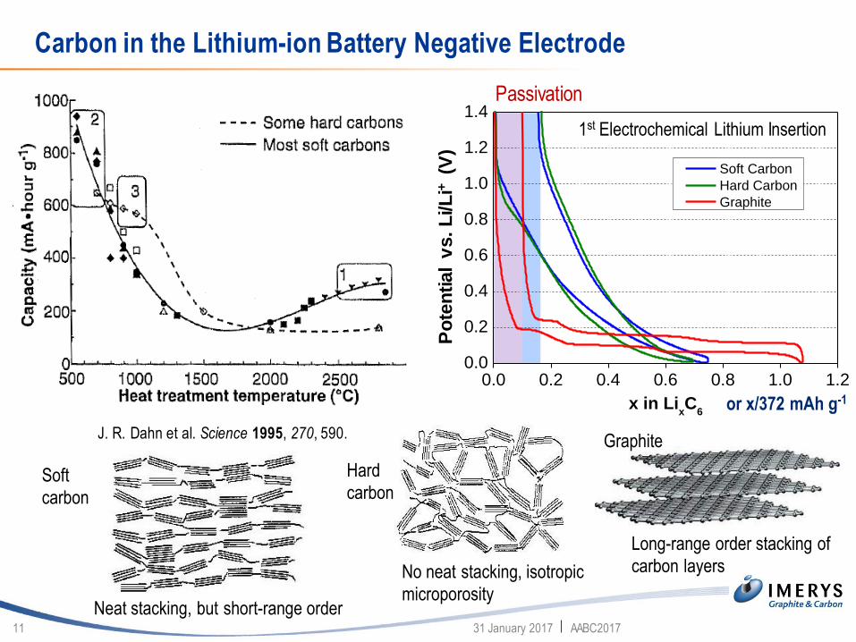
J. R. Dahn et al. Science 1995, 270, 590.
0.0 0.2 0.4 0.6 0.8 1.0 1.20.0
0.2
0.4
0.6
0.8
1.0
1.2
1.4
Po
ten
tia
l vs. L
i/L
i+
x in LixC
6
Soft Carbon
Hard Carbon
Graphite
or x/372 mAh g-1
Passivation
1st Electrochemical Lithium Insertion
Po
ten
tial
vs. L
i/L
i+(V
)Graphite
Long-range order stacking of
carbon layers
Neat stacking, but short-range order
No neat stacking, isotropic
microporosity
Soft
carbon
Hard
carbon
Natural and Synthetic Graphite Active Materials
31 January 2017 AABC201712
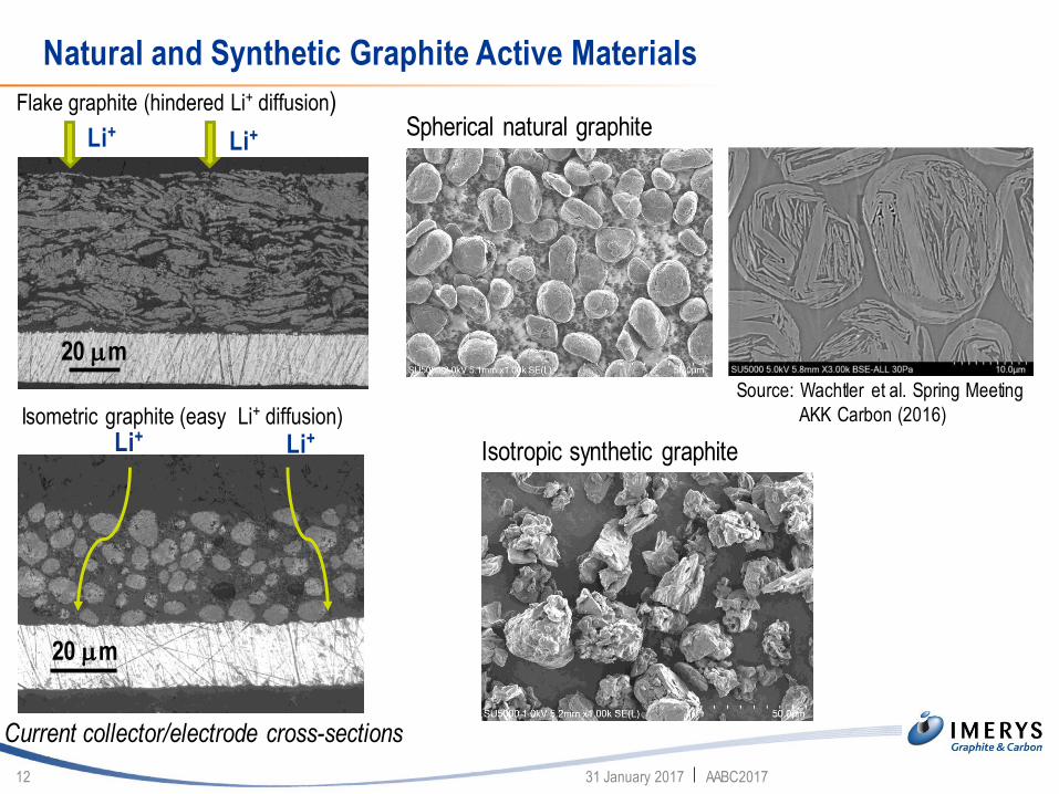
Li+Li+
20 mm
Flake graphite (hindered Li+ diffusion)
Isometric graphite (easy Li+ diffusion)
20 mm
Li+Li+
Current collector/electrode cross-sections
Spherical natural graphite
Isotropic synthetic graphite
Source: Wachtler et al. Spring Meeting
AKK Carbon (2016)
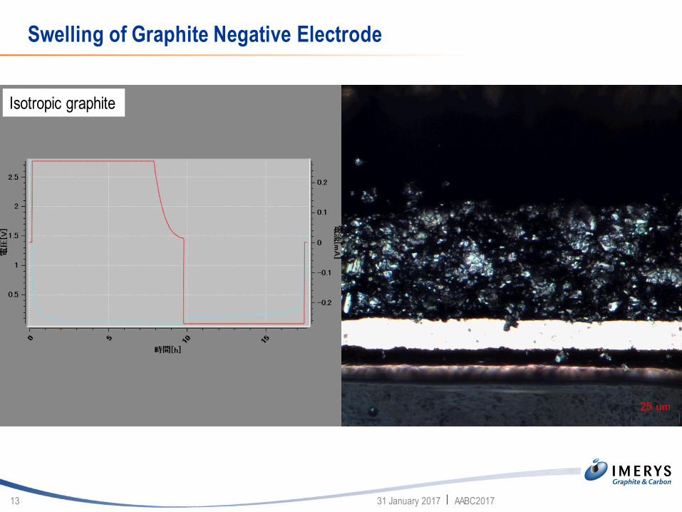
Swelling of Graphite Negative Electrode
31 January 2017 AABC201713
Isotropic graphite
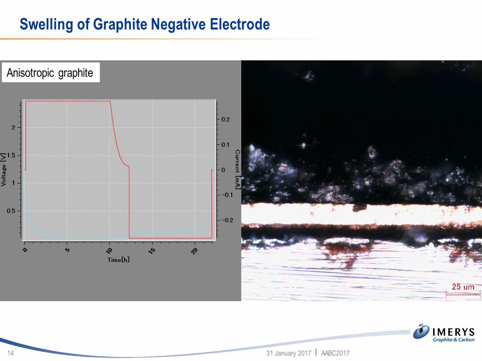
Swelling of Graphite Negative Electrode
31 January 2017 AABC201714
Anisotropic graphite

Graphite Anode Materials for FEV Lithium-Ion Batteries
31 January 2017 AABC201715
Development objectives at cell level Development objectives at material (electrode) level
Durability
Safety
Energy Power
Chargeability
Trade-off
▪ High crystallinity synthetic or natural graphite
(min. 340 Ah kg-1, min. 500 Ah L-1)
▪ Low surface area
(min. 90 % coulombic efficieny in the 1st cycle)
▪ Low crystalline surface morphology
(stable SEI, low cell gassing)
▪ Isotropic texture, low swelling
(min. 3000 cycles/80 % capacity retention)
▪ Isotropic texture and particle shape
(3C discharge/80 % capacity retention)
▪ Consistent batch-to-batch quality, surface properties
(easy processing in aqueous electrode manufacturing)
▪ Sustainable large scale manufacturing processes
(Low CO2 footprint, environmentally benign, high yield)
▪ Cost efficient
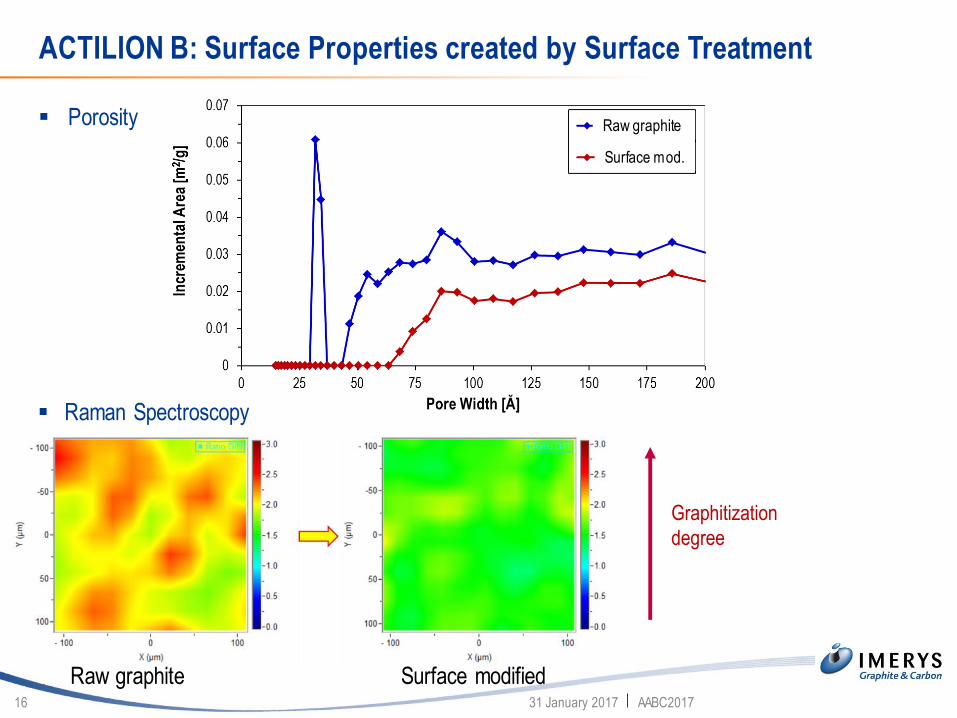
ACTILION B: Surface Properties created by Surface Treatment
31 January 2017 AABC201716
▪ Raman Spectroscopy
▪ Porosity
Surface mod.
Raw graphite
Surface modifiedRaw graphite
Graphitization
degree
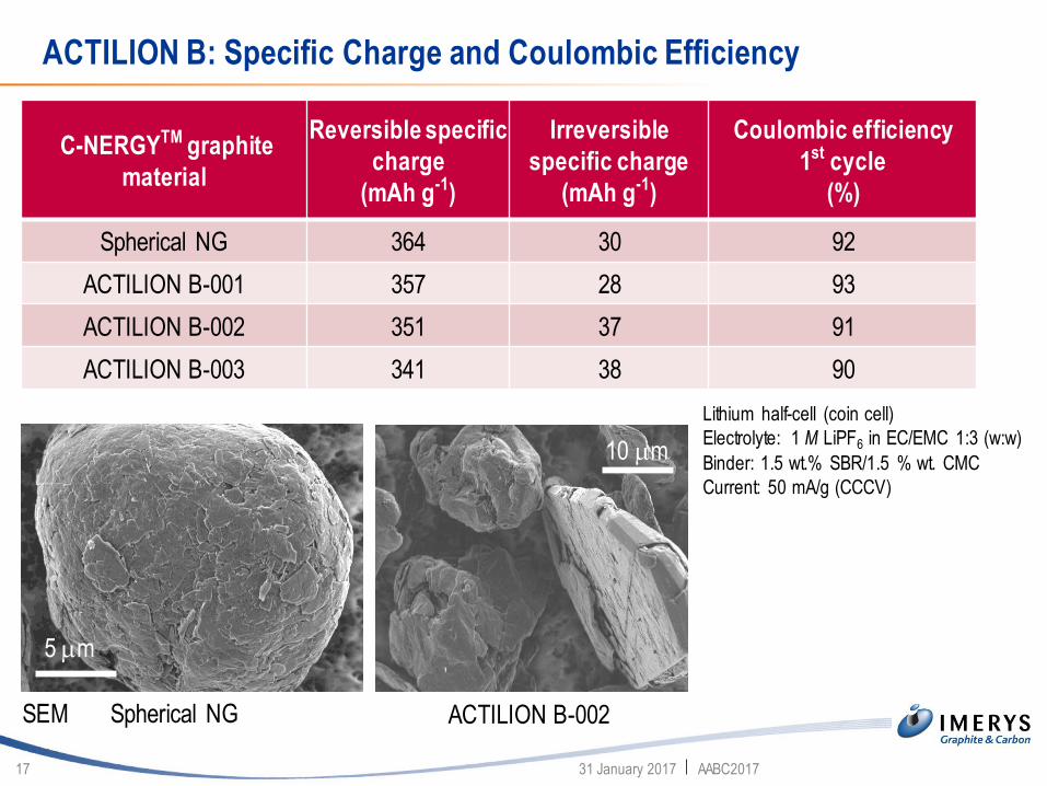
ACTILION B: Specific Charge and Coulombic Efficiency
31 January 2017 AABC201717
10 mm
5 mm
C-NERGYTM graphite
material
Reversible specific
charge
(mAh g-1)
Irreversible
specific charge
(mAh g-1)
Coulombic efficiency
1st cycle
(%)
Spherical NG 364 30 92
ACTILION B-001 357 28 93
ACTILION B-002 351 37 91
ACTILION B-003 341 38 90
Spherical NG ACTILION B-002
Lithium half-cell (coin cell)
Electrolyte: 1 M LiPF6 in EC/EMC 1:3 (w:w)
Binder: 1.5 wt.% SBR/1.5 % wt. CMC
Current: 50 mA/g (CCCV)
SEM
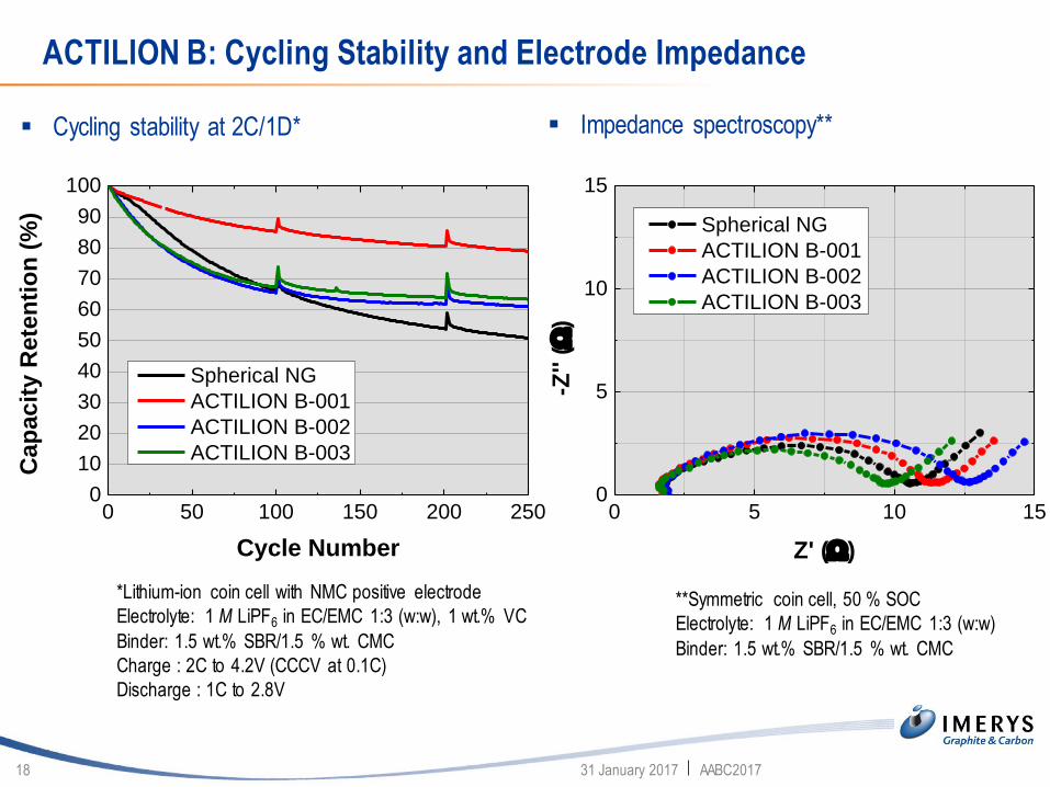
ACTILION B: Cycling Stability and Electrode Impedance
31 January 2017 AABC201718
**Symmetric coin cell, 50 % SOC
Electrolyte: 1 M LiPF6 in EC/EMC 1:3 (w:w)
Binder: 1.5 wt.% SBR/1.5 % wt. CMC
*Lithium-ion coin cell with NMC positive electrode
Electrolyte: 1 M LiPF6 in EC/EMC 1:3 (w:w), 1 wt.% VC
Binder: 1.5 wt.% SBR/1.5 % wt. CMC
Charge : 2C to 4.2V (CCCV at 0.1C)
Discharge : 1C to 2.8V
▪ Cycling stability at 2C/1D* ▪ Impedance spectroscopy**
0 50 100 150 200 2500
10
20
30
40
50
60
70
80
90
100
Cap
ac
ity R
ete
nti
on
(%
)
Cycle Number
Spherical NG
ACTILION B-001
ACTILION B-002
ACTILION B-003
0 5 10 150
5
10
15
-Z'' (
)Z' ()
Spherical NG
ACTILION B-001
ACTILION B-002
ACTILION B-003

ACTILION B: Electrode Resistance and High Currant Rate Discharge
31 January 2017 AABC201719
DCR ()
Spherical NG 19.5
ACTILION B-001 25.5
ACTILION B-002 22.7
ACTILION B-003 24.1
2C/0.2C (%) 3C/0.2C (%)
Spherical NG 96.0 72.0
ACTILION B-001 97.5 74.2
ACTILION B-002 92.2 66.7
ACTILION B-003 98.5 78.9
*Symmetric coin cell, 50 % SOC, 1C pulse (20 s)
Electrolyte: 1 M LiPF6 in EC/EMC 1:3 (w:w)
Binder: 1.5 wt.% SBR/1.5 % wt. CMC
▪ Direct current resistance of electrodes* ▪ High current rate continuous discharge**
**Lithium coin half-cell
Electrolyte: 1 M LiPF6 in EC/EMC 1:3 (w:w)
Binder: 1.5 wt.% SBR/1.5 % wt. CMC
0 20 40 60 80 1000.0
0.5
1.0
1.5
Po
ten
tia
l v
s.
Li/L
i+
SOC (%)
0.2C
2C
3C
ACTILION B-003

CO2 Footprint of the C-NERGYTM ACTILION B Negative Electrode Materials
31 January 2017 AABC201720
To
n o
f C
O2e
per
to
n o
f g
rap
hit
e p
rod
uce
d
4,7 t 12,4 t 13.0 t
Electric Vehicles
From 250 000 units produced in 2015 to 2 000 000 units produced In 2025 using a CAGR of 23,11%
Simulation based on a 25kWh battery pack model
Up to 1988 ktonsof CO2e SAVED
Process
Raw materials &
transport
4
8
12
0
Synthetic graphite Natural graphiteACTILION B-002
64% reduction of CO2e per ton of
graphite produced
Study by: tallis consulting (2016)
1990 1992 1994 1996 1998 2000 2002 2004 2006 2008 2010 2012 2014 2016
0
500
1000
1500
2000
2500
3000
3500
4000
Cell
Ca
pac
ity
[m
Ah
]
Calendar Year
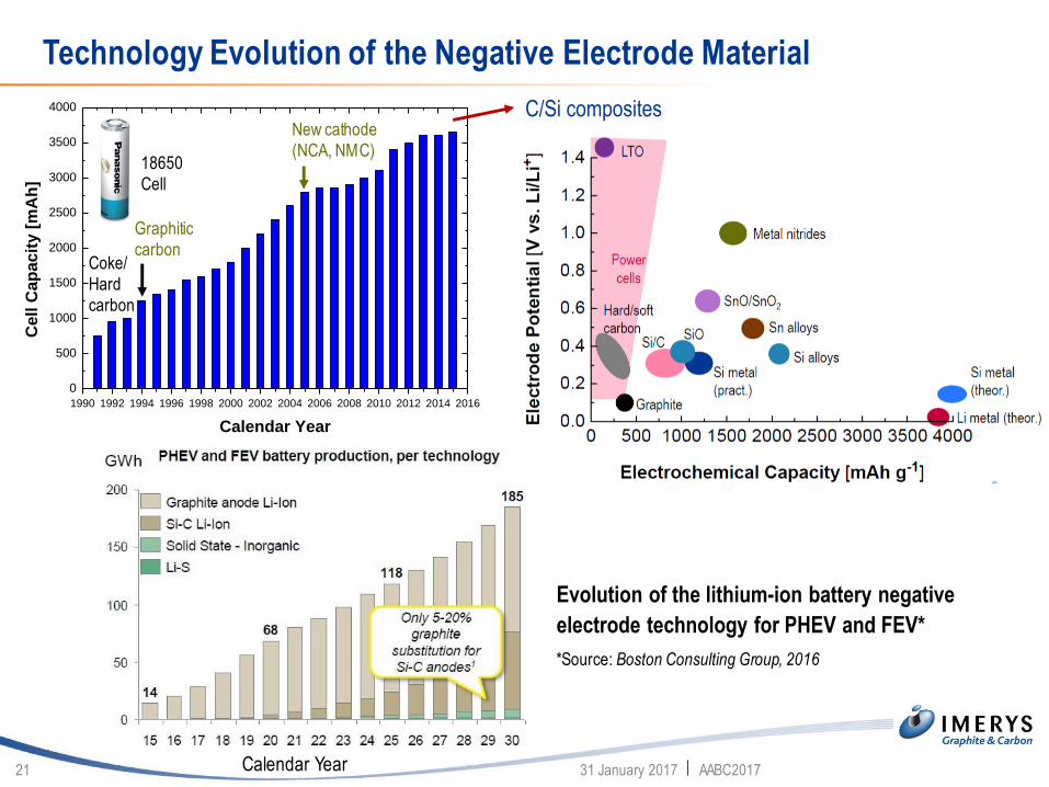
Technology Evolution of the Negative Electrode Material
31 January 2017 AABC201721
Coke/
Hard
carbon
Graphitic
carbon
New cathode
(NCA, NMC)
C/Si composites
18650
Cell
Evolution of the lithium-ion battery negative
electrode technology for PHEV and FEV*nd FEV
2015-2*Source: Boston Consulting Group, 2016
Calendar Year
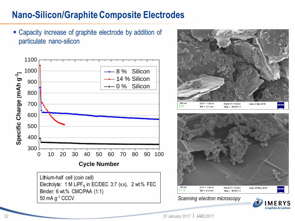
Nano-Silicon/Graphite Composite Electrodes
31 January 2017 AABC201722
0 10 20 30 40 50 60 70 80 90 100300
400
500
600
700
800
900
1000
1100
Sp
ec
ific
Ch
arg
e [m
Ah
g-1
]
Cycle Number
8 % Silicon
14 % Silicon
0 % Silicon
▪ Capacity increase of graphite electrode by addition of
particulate nano-silicon
Lithium-half cell (coin cell)
Electrolyte: 1 M LiPF6 in EC/DEC 3:7 (v,v), 2 wt.% FEC
Binder: 6 wt.% CMC/PAA (1:1)
50 mA g-1 CCCV Scanning electron microscopy

Influence of Carbon Additives on Silicon/Carbon Composite Electrode
Performance
31 January 2017 AABC201723
Negative electrode composition Electrochemical results
Silicon
[wt.% ]
ACTILION 1
[wt.% ]
SFG 15L
[wt.% ]
BND 15
[wt.% ]
Super C45
[wt.% ]
CMC/PAA Discharge
capacity 5th
cycle
[mAh/g]
Relative
capacity
loss cycle
5-15 [% ]
1st Cycle
coulombic
efficiency
[% ]
Nano-
Silicon
Graphite Graphite Graphite Carbon
black
Binder
material
14 80.0 6.0 481 27 86
14 68.8 5.6 5.6 6.0 665 10 84
14 72.0 5.6 2.4 6.0 615 12 84
14 72.0 5.6 2.4 6.0 619 14 86

Carbon in Electrochemical Lithium-Ion Cells
31 January 2017 AABC201724
Li+
negative electrode (anode)
positive electrode (cathode)
e-
separator IMERYS carbon products are
inside the positive and the
negative electrode
electrolyte (in electrode pores)
carbon active material
conductive graphite
conductive carbon black
binder
electrolyte (in electrode pores)
active material
conductive graphite
conductive carbon black
binder
copper
current collector
aluminum
current collector
current collector
coating
+
-

Thank you for your attention.
The support of the IMERYS R&D team is
gratefully acknowledged.