carbon-based nanomaterials in biomass-based fuel-fed fuel ... · pdf fileenergy conversion...
TRANSCRIPT
sensors
Review
Carbon-Based Nanomaterials in Biomass-BasedFuel-Fed Fuel Cells
Le Quynh Hoa 1,* ID , Mun’delanji C. Vestergaard 2,* and Eiichi Tamiya 3
1 Federal Institute for Materials Research and Testing (BAM), Unter den Eichen 87, Berlin 12205, Germany2 Department of Biochemical Science and Technology, Faculty of Agriculture, Kagoshima University,
Kagoshima 890-0065, Japan3 Department of Applied Physics, Osaka University, 2-1 Yamadaoka, Suita, Osaka 565-0871, Japan;
[email protected]* Correspondence: [email protected] (L.Q.H.); [email protected] (M.C.V.);
Tel.: +49-308-104-4667 (L.Q.H.); +81-99-285-3520 (M.C.V.)
Received: 10 October 2017; Accepted: 7 November 2017; Published: 10 November 2017
Abstract: Environmental and sustainable economical concerns are generating a growing interest inbiofuels predominantly produced from biomass. It would be ideal if an energy conversion devicecould directly extract energy from a sustainable energy resource such as biomass. Unfortunately, upto now, such a direct conversion device produces insufficient power to meet the demand of practicalapplications. To realize the future of biofuel-fed fuel cells as a green energy conversion device, effortshave been devoted to the development of carbon-based nanomaterials with tunable electronic andsurface characteristics to act as efficient metal-free electrocatalysts and/or as supporting matrix formetal-based electrocatalysts. We present here a mini review on the recent advances in carbon-basedcatalysts for each type of biofuel-fed/biofuel cells that directly/indirectly extract energy from biomassresources, and discuss the challenges and perspectives in this developing field.
Keywords: carbon-based nanomaterials; biofuel cells; biomass; carbon nanotubes; graphene;carbon nanodots
1. Introduction
1.1. From Biomass to Biofuels: Conventional Processes and Challenges
Biomass, a renewable source of fuel made from biological materials such as plants and animalwaste, has been used as the primary energy source since ancient times. In particular wood serves asthe principle energy source till the dawn of the industrial revolution when fossil fuels became theabsolute dominator. Besides a lot of advantages, the reproduction of fossil fuels is impossible makingit a deathly Achilles heel compared to wood crops, the most widely used biomass resource, whichcan re-grow every 50–100 years. Moreover, fossil fuel reservoirs are going to emptying and its relatedenvironmental problems are severe. Therefore reducing dependence on fossil fuels becomes a moreand more ultimate request. One of current solutions is to transform a variety of agricultural crops andtheir byproducts into a supplementary energy source.
Currently, to extract energy, woody plants and grasses are used in several ways: The first is thesame as our accentors did a hundred years ago which is to burn woody material and grasses to provideheat and/or steam for households or for generating electric power. This approach is still widely usedin many underdeveloped countries. The second is to thermally decompose biomass under variedconditions such as pressure, temperature and catalyst to obtain combustible products. Another way isto ferment carbohydrates and then distil them to obtain ethanol, a highly ranked liquid fuel that can beblended with gasoline for motor vehicle use. Last but not the least, is the use of an anaerobic digestion
Sensors 2017, 17, 2587; doi:10.3390/s17112587 www.mdpi.com/journal/sensors

Sensors 2017, 17, 2587 2 of 21
processes in which microorganisms breakdown biomass in the absence of oxygen to produce biogas(mainly CO2 and CH4). These gaseous fuels can be further purified in an upgrader system to moredesirable forms that are suitable for engines, gas turbines, fuel cells, boilers, industrial heaters, etc.albeit at some loss of energy [1–5]. Manufacturing combustible fuels from biomass inevitably involvesintensive energy processes such as drying, pulverizing to minimize heat-transfer resistance and residueremoval which not only results in partial loss of total heating value but also increases the cost of theconversion process. Consequently, researchers are looking for an optimum breakdown process coupledwith effective energy conversion devices, which can gain a positive net energy and at the same timehave low to acceptable costs. To that end, biomass-based electricity could be an appropriate answer.
As shown in Figure 1, the convention process to generate energy from biomass, especiallyelectricity, consists of three main processes: (1) scarification (or breakdown process) to convertbiomass to smaller components that are easier to be degraded; (2) fermentation to convert these smallcomponents to bio-fuels; and (3) energy conversion process that generates electricity from bio-fuelsusing fuel cells. In order to vastly improve overall efficiency, the scientific portfolio is organizedinto three core strategies: (1) improve plants; (2) improve processing; and (3) improve catalysts,targeting the three main processes, respectively [6–20]. Ideally, crude and abundant fuel sources suchas cellulose or starch could be utilized directly [15]. However, despite the enormous efforts by scientistsworldwide, this goal seems too far from real practical implementation. Thus, researchers aim to increaseenergy density and the degradability of plants such as grasses and other non-traditional oil crops byunderstanding, and manipulating metabolic flux and genetic modification [6,7]. Another solutionis to improve the breakdown and fermentation processes in which the primitive biomass sourcesare degraded into smaller sources such as glucose and/or other monosaccharides, and ultimately tobio-hydrogen and bio-ethanol [8–14]. This research trend is focusing on the development of geneticallymodified microorganisms and efficient low-cost enzymes. Especially, bio-hydrogen and cellulosicethanol-producing microbes are at the center of this strategy. After breaking down biomass sources intobiofuels, the last challenge is utilizing as much as possible, the energy stored in the chemical bonds byenergy conversion devices-fuel cells. At this stage, nanotechnology is being employed to improve cellperformance, increase durability, and reduce the cost [16]. For example, precious metal electrocatalystsused are reduced to the nanoscale, ensuring a high catalytic surface area and minimizing the amountof precious metal used to maintain high performance. Thus far, many researchers have been studyinginorganic nanostructured catalysts including alloys, bimetallic, and ternary metallics in order to notonly reduce the noble metal loading but also create synergistic effects to enhance catalytic performanceas well as durability [17]. Differing from the inorganic approach, a new strategy is focusing onorganic-based nanomaterials, mostly carbon-based, as supporting matrices to fine-tune the catalyticactivities of low-loading noble or non-noble metals toward desired products [18]. Graphene, forinstance, when coated with cobalt and cobalt-oxide nanoparticles, is reported to be able to catalyzethe oxygen reduction reaction on the cathode side of fuel cells, nearly as well as platinum does and issubstantially more durable [19]. A catalyst made of iron nanoparticles confined inside pea-pod-likecarbon nanotubes exhibits a high activity and remarkable stability as a cathode catalyst in polymerelectrolyte membrane fuel cells [20].
In this mini-review, we discuss the main results from recent studies on fuel cells that directly orindirectly utilized biomass as fuels and carbon-based nanomaterials as catalytic materials. From thediscussion, the challenges will be made more succinct, exposing the future prospects of thisresearch trend.

Sensors 2017, 17, 2587 3 of 21Sensors 2017, 17, 2587 3 of 21
Figure 1. The conventional process and challenges in converting biomass sources into biofuels and ultimately generate energy in form of electricity.
1.2. Biofuel-Fed Fuel Cells and Biofuel Cells
The first electrochemical cell (fuel cell) akin to the Volta cell (a battery) was discovered in 1839 by Sir William R. Grove [21]. A fuel cell is an electrochemical “device” that continuously converts chemical energy into electric energy (and some heat) for as long as fuel and oxidants are supplied. A fuel cell shares similar electrochemical properties with a battery. However, it does not need recharging, operates quietly and efficiently. A fuel cell also is considered as an ideal substitution for combustion engines in the near future. Thermodynamically, the most striking difference is that thermal engines are limited by the Carnot efficiency while fuel cells are not. The limiting factors are the temperature at which the heat enters the engine, TH, and the temperature of the environment into which the engine exhausts its waste heat, TC. No device converting heat into mechanical energy, regardless of its construction, can exceed the Carnot cycle efficiency: η ≤ 1-TC/TH. In contrast, since all the components in fuel cell systems work at the same temperature (T = TH = TC) it is clearly not limited by the Carnot’s theorem. This is because the Carnot’s theorem applies to engines converting thermal energy into work, whereas fuel cells convert chemical energy into work. Therefore, the energy conversion efficiency can reach more than 50% and can be enhanced by stacking single fuel cells and utilizing a vast range of fuel sources such as hydrogen, natural gas, methanol, and ethanol. Figure 2 shows the summary of the power ranges and applications of different types of fuel cells [21–23]. However, the problem is that even with hydrogen fuel cells, the most successful proton exchange membrane fuel cell (PEMFC) system, there are huge challenges including fuel distribution and safety issues; and methanol of direct methanol fuel cell (DMFC) is toxic. In addition, the fuel production is not without concern. It has its own print in greenhouse gas emission and climate change. Today 96% of all hydrogen is derived from fossil fuels, with 48% from natural gas, 30% from hydrocarbons, 18% from coal, and about 4% from electrolysis [24]. The situation is similar for methanol production since it is produced by steam-methane reforming from natural gas source. Thus, researchers have been pushed to search for more practical, safer and “greener” solution(s): biomass derived-biofuels. For biofuel cells, it is not necessary to use biomass as fuel. “Bio”-fuel cells use biocatalytic systems such as enzymes or microorganisms as catalysts. In the frame of green-chemistry, this review discusses the applications of CBNs for biomass-based fuel-fed fuel cells, which include biofuel cells and do not exclude the fuel cells that utilize non-biocatalytical systems.
Figure 1. The conventional process and challenges in converting biomass sources into biofuels andultimately generate energy in form of electricity.
1.2. Biofuel-Fed Fuel Cells and Biofuel Cells
The first electrochemical cell (fuel cell) akin to the Volta cell (a battery) was discovered in 1839 bySir William R. Grove [21]. A fuel cell is an electrochemical “device” that continuously converts chemicalenergy into electric energy (and some heat) for as long as fuel and oxidants are supplied. A fuel cellshares similar electrochemical properties with a battery. However, it does not need recharging, operatesquietly and efficiently. A fuel cell also is considered as an ideal substitution for combustion engines inthe near future. Thermodynamically, the most striking difference is that thermal engines are limited bythe Carnot efficiency while fuel cells are not. The limiting factors are the temperature at which theheat enters the engine, TH, and the temperature of the environment into which the engine exhausts itswaste heat, TC. No device converting heat into mechanical energy, regardless of its construction, canexceed the Carnot cycle efficiency: η ≤ 1 − TC/TH. In contrast, since all the components in fuel cellsystems work at the same temperature (T = TH = TC) it is clearly not limited by the Carnot’s theorem.This is because the Carnot’s theorem applies to engines converting thermal energy into work, whereasfuel cells convert chemical energy into work. Therefore, the energy conversion efficiency can reachmore than 50% and can be enhanced by stacking single fuel cells and utilizing a vast range of fuelsources such as hydrogen, natural gas, methanol, and ethanol. Figure 2 shows the summary of thepower ranges and applications of different types of fuel cells [21–23]. However, the problem is thateven with hydrogen fuel cells, the most successful proton exchange membrane fuel cell (PEMFC)system, there are huge challenges including fuel distribution and safety issues; and methanol of directmethanol fuel cell (DMFC) is toxic. In addition, the fuel production is not without concern. It hasits own print in greenhouse gas emission and climate change. Today 96% of all hydrogen is derivedfrom fossil fuels, with 48% from natural gas, 30% from hydrocarbons, 18% from coal, and about4% from electrolysis [24]. The situation is similar for methanol production since it is produced bysteam-methane reforming from natural gas source. Thus, researchers have been pushed to searchfor more practical, safer and “greener” solution(s): biomass derived-biofuels. For biofuel cells, it isnot necessary to use biomass as fuel. “Bio”-fuel cells use biocatalytic systems such as enzymes ormicroorganisms as catalysts. In the frame of green-chemistry, this review discusses the applications ofCBNs for biomass-based fuel-fed fuel cells, which include biofuel cells and do not exclude the fuelcells that utilize non-biocatalytical systems.
Sensors 2017, 17, 2587 4 of 21Sensors 2017, 17, 2587 4 of 21
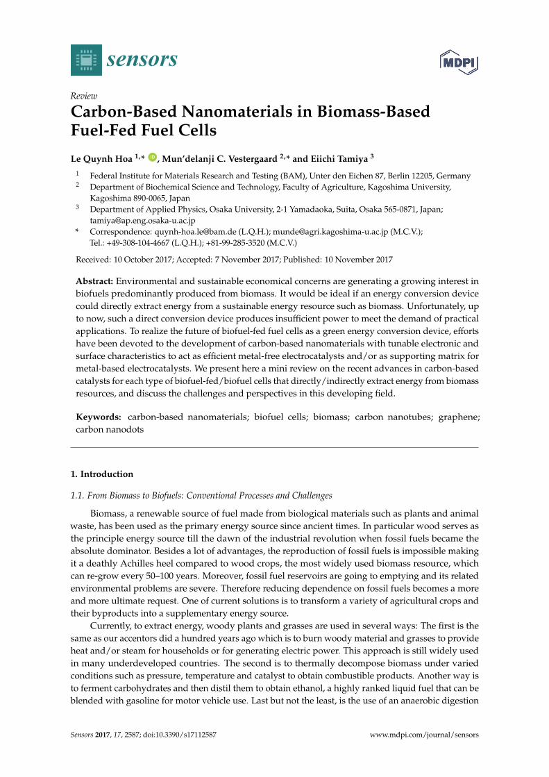
Figure 2. Summary of applications and main advantages of different types fuel cells (CHP stands for combined heat and power systems. The power unit is Watt).
1.3. Carbon-Based Nanomaterials
Carbon-based nanomaterials (CBNs), were discovered about 150 years ago, remarkably in 1991 by a physicist, Sumio Iijima of Nippon Electric Company (NEC) Corporation, Japan, who published a ground-breaking paper in Nature on multiwalled carbon nanotubes (CNTs) [25], and in 2004 by Novoselov with the mechanical exfoliation of graphite to produce the first single layer graphene [26]. They have since been thoroughly characterized, and extensively developed for a wide range of fields from industrial applications such as high-strength materials, nanoscale electronic, high efficiency electron emitters, to research including biosensors, drug delivery systems, and tissue scaffold reinforcement [27]. CBNs have enjoyed this wide application due to their unique combinations of mechanical, optical, thermal, and electrical properties. Graphene, for example, is incredibly strong with the tensile strength of ~130 GPa, for a defect free single layer, Young’s modulus of 1 Tpa, third order elastic stiffness ≈ 2 Tpa; and at the same time is very flexible and light (0.77 mg m−2) with a very high specific surface area (~2630 m2 g−1) [28]. Figure 3 shows the CBNs that have been significantly used and can potentially be used for biofuel-fed fuel cells.
One of the CBNs characteristics, which is important in fuel cell applications, is high electronic conductivity. In the past, this could be achieved by amorphous carbon, which possesses not only good conductivity but also large surface area and porosity. With CBNs, not only is the conductivity much more increased, but also the weight and size of electrode could be extremely reduced. For instance, electronic transport in carbon nanotubes ballistically occurs over long nanotube lengths due to their nearly one-dimensional structure, thus enabling them to carry high current without heating effect. When employed as electrode materials for fuel cells, a network of CNTs as catalytic supports not only enhances the active surface area, mass transport of fuels, conductivity, and much more resistance to corrosion but also is involved in the catalytic mechanism (with or without precious metals) toward desired products with faster reaction kinetics, leading to higher power density and energy conversion efficiency [29–34]. Comparable and higher catalytic effects compared to that of traditional Pt/C have been also observed in the case of graphene doped/co-doped with various heteroatoms and their composites with metal/metal oxides and/or conducting polymers. Table 1 provides a summary of the most recent achievemenst of CBNs, from 2010 (top) to 2017 (bottom), in cathodic catalytic systems that deal with oxygen reduction reaction, a main limiting factor to the cell performance, especially in the case of microbial fuel cells (MFCs). Further applications of carbon-based nanomaterials in anodic catalytic systems, which deals with oxidation reactions of biomass-based fuels are discussed in the coming sections.
Figure 2. Summary of applications and main advantages of different types fuel cells (CHP stands forcombined heat and power systems. The power unit is Watt).
1.3. Carbon-Based Nanomaterials
Carbon-based nanomaterials (CBNs), were discovered about 150 years ago, remarkably in1991 by a physicist, Sumio Iijima of Nippon Electric Company (NEC) Corporation, Japan, whopublished a ground-breaking paper in Nature on multiwalled carbon nanotubes (CNTs) [25], andin 2004 by Novoselov with the mechanical exfoliation of graphite to produce the first single layergraphene [26]. They have since been thoroughly characterized, and extensively developed for a widerange of fields from industrial applications such as high-strength materials, nanoscale electronic, highefficiency electron emitters, to research including biosensors, drug delivery systems, and tissue scaffoldreinforcement [27]. CBNs have enjoyed this wide application due to their unique combinations ofmechanical, optical, thermal, and electrical properties. Graphene, for example, is incredibly strongwith the tensile strength of ~130 GPa, for a defect free single layer, Young’s modulus of 1 Tpa, thirdorder elastic stiffness ≈ 2 Tpa; and at the same time is very flexible and light (0.77 mg m−2) with a veryhigh specific surface area (~2630 m2 g−1) [28]. Figure 3 shows the CBNs that have been significantlyused and can potentially be used for biofuel-fed fuel cells.
One of the CBNs characteristics, which is important in fuel cell applications, is high electronicconductivity. In the past, this could be achieved by amorphous carbon, which possesses not only goodconductivity but also large surface area and porosity. With CBNs, not only is the conductivity muchmore increased, but also the weight and size of electrode could be extremely reduced. For instance,electronic transport in carbon nanotubes ballistically occurs over long nanotube lengths due to theirnearly one-dimensional structure, thus enabling them to carry high current without heating effect.When employed as electrode materials for fuel cells, a network of CNTs as catalytic supports not onlyenhances the active surface area, mass transport of fuels, conductivity, and much more resistance tocorrosion but also is involved in the catalytic mechanism (with or without precious metals) towarddesired products with faster reaction kinetics, leading to higher power density and energy conversionefficiency [29–34]. Comparable and higher catalytic effects compared to that of traditional Pt/C havebeen also observed in the case of graphene doped/co-doped with various heteroatoms and theircomposites with metal/metal oxides and/or conducting polymers. Table 1 provides a summary ofthe most recent achievemenst of CBNs, from 2010 (top) to 2017 (bottom), in cathodic catalytic systemsthat deal with oxygen reduction reaction, a main limiting factor to the cell performance, especially inthe case of microbial fuel cells (MFCs). Further applications of carbon-based nanomaterials in anodiccatalytic systems, which deals with oxidation reactions of biomass-based fuels are discussed in thecoming sections.

Sensors 2017, 17, 2587 5 of 21
Table 1. Summary of carbon-based nanomaterials (CBNs) recent achievements in microbial fuel cells (MFCs) towards enhanced cathode performance.
Reactor Type Anodic Supporting Materials Cathode Materials Power Density (mW m−2) Comparision to Pt/C or Bare Materials Ref.
250 mL double chambers Graphite granule Pt/C 1470 ± 10 - [35]
250mL double chambers Graphite granule Co3O4/N doped graphene 1340 ± 10 Comparable to Pt/C [35]
6 mL single chamber Carbon paper Co/Fe/N/CNTs 751 1.5 times > Pt/C [36]
80 mL double chamber Carbon fiber N-doped CNTs on C cloth 1600 ± 50 12.8% > Pt/C [37]
Single chamber Carbon felts Fe–N-functionalized graphene 1149.8 2.1 times > Pt/C [38]
Single chamber Carbon cloth Graphene supported Pt–Co 1378 Comparable to Pt/C [39]
Sediment MFCs Graphite felt Polyaniline-Graphene nanosheets 99 116 times > Graphite [40]
Double chamber - N/S co-doped carbon nanosheets 1500 Comparable to Pt/C [41]
15 mL sediment single chamber MWNT coating Graphite MWNT coating Graphite 214.7 ± 9.9 1.6 times higher than that of bare graphite [42]
Single chamber Carbon cloth Graphene/poly(3,4-ethylenedioxythiophene)/Fe3O4 3525 8.2 times > Carbon cloth [43]
Double chamber Carbon brush N-doped Graphene/CoNi alloy encased withinbamboo-like CNTs 2000 Comparable to Pt/C [44]
210 mL double chamber Carbon paper CNTs/Polypyrrole 113.5 Comparable to Pt/C [45]
Single chamber Graphite fiber brush Ag/Fe/N/C 1791 1.5 times > Pt/C [46]
20 mL single chamber N-Ni-carbon nanofibers N-doped polymer-Ni–carbon nanofibers 1690 ± 30 - [47]
1.5 L single chamber Carbon fiber Co-doped Carbon nanofibers 92 Stable more than 6000 h [48]

Sensors 2017, 17, 2587 6 of 21
Sensors 2017, 17, 2587 6 of 21
Figure 3. Carbon-based nanomaterials that have been and have potential to be used for biofuel-fed fuel cells.
2. Direct Energy Conversion Challenges and Applications of Carbon-Based Nanomaterials
2.1. Cellulose and Cellulosic Biomass Fuel Cells
Since more than 70% of biomass is made of cellulose, the most obvious biomass target for biofuel-fed fuel cells is cellulose. However, cellulose, a straight chain natural polymer (C6H10O5)n, is insoluble in water and as well as most other organic solvents, must first be hydrolyzed to a soluble substrate that can be oxidized on the surface of anode electrode or to be taken up by the cell. Sugano et al. succeeded in dissolving pure cellulose powder in alkaline solution using a freezing/thawing process and oxidizing it on gold electrode as anode, producing the first direct cellulose fuel cell with power density of 44 mW m−2 (150 mV and ~450 mA m−2) [15]. Recognizing the high-cost and active surface limitation of the gold-based electrodes, further research was done by the same group. They utilized functionalized carbon nanotubes as catalytic system, which is capable of cleaving ß-1,4-glycosyl bonds of the sugar substrate in the same way as natural enzyme, cellulase (Figure 4) [49].
Figure 4. Proposed biomimetic functionalized carbon nanotubes-based catalyst for direct breaking down of cellulose. Reprinted with permission from ref. [49]. Copyright 2011, RSC.
Figure 3. Carbon-based nanomaterials that have been and have potential to be used for biofuel-fedfuel cells.
2. Direct Energy Conversion Challenges and Applications of Carbon-Based Nanomaterials
2.1. Cellulose and Cellulosic Biomass Fuel Cells
Since more than 70% of biomass is made of cellulose, the most obvious biomass target forbiofuel-fed fuel cells is cellulose. However, cellulose, a straight chain natural polymer (C6H10O5)n,is insoluble in water and as well as most other organic solvents, must first be hydrolyzed toa soluble substrate that can be oxidized on the surface of anode electrode or to be taken up bythe cell. Sugano et al. succeeded in dissolving pure cellulose powder in alkaline solution usinga freezing/thawing process and oxidizing it on gold electrode as anode, producing the first directcellulose fuel cell with power density of 44 mW m−2 (150 mV and ~450 mA m−2) [15]. Recognizing thehigh-cost and active surface limitation of the gold-based electrodes, further research was done by thesame group. They utilized functionalized carbon nanotubes as catalytic system, which is capable ofcleaving ß-1,4-glycosyl bonds of the sugar substrate in the same way as natural enzyme, cellulase(Figure 4) [49].
Sensors 2017, 17, 2587 6 of 21
Figure 3. Carbon-based nanomaterials that have been and have potential to be used for biofuel-fed fuel cells.
2. Direct Energy Conversion Challenges and Applications of Carbon-Based Nanomaterials
2.1. Cellulose and Cellulosic Biomass Fuel Cells
Since more than 70% of biomass is made of cellulose, the most obvious biomass target for biofuel-fed fuel cells is cellulose. However, cellulose, a straight chain natural polymer (C6H10O5)n, is insoluble in water and as well as most other organic solvents, must first be hydrolyzed to a soluble substrate that can be oxidized on the surface of anode electrode or to be taken up by the cell. Sugano et al. succeeded in dissolving pure cellulose powder in alkaline solution using a freezing/thawing process and oxidizing it on gold electrode as anode, producing the first direct cellulose fuel cell with power density of 44 mW m−2 (150 mV and ~450 mA m−2) [15]. Recognizing the high-cost and active surface limitation of the gold-based electrodes, further research was done by the same group. They utilized functionalized carbon nanotubes as catalytic system, which is capable of cleaving ß-1,4-glycosyl bonds of the sugar substrate in the same way as natural enzyme, cellulase (Figure 4) [49].
Figure 4. Proposed biomimetic functionalized carbon nanotubes-based catalyst for direct breaking down of cellulose. Reprinted with permission from ref. [49]. Copyright 2011, RSC. Figure 4. Proposed biomimetic functionalized carbon nanotubes-based catalyst for direct breaking
down of cellulose. Reprinted with permission from ref. [49]. Copyright 2011, RSC.

Sensors 2017, 17, 2587 7 of 21
Since cellulose is biodegradable, another approach is using microbial fuel cells (MFCs).This system uses microorganism(s) to hydrolyze cellulose, then oxidize its metabolites, whichareat the same time electrochemically active. Thus, they act as electron acceptors. Based on thisprinciple, Rismani-Yazdi and colleagues succeeded in using rumen microbiota containing both strictand facultative anaerobes, which effectively hydrolyze cellulose, and conserve energy via anaerobicrespiration or fermentation [50]. This cellulose-fed MFCs, consisting of two chambers separatedby Ultrex proton-exchange membrane and graphite plates as electrodes gained a maximum powerdensity of 55 mW m−2 (1.5 mA, 313 mV) and the current was sustained for over two months with theperiodically supplementation of cellulose as electron donor. To improve the power density, Rezaeiet al. increased the cathode volume (three times larger), ammonia-treated carbon cloth (type A;E-Tek, United States) with a total surface area of 1.13 cm2 was used as anode and five two strands of15-cm-long carbon fiber were used as cathode [51]. Using this modified U-tube MFC and strain ATCC13047T, a power density of 5.4 ± 0.3 mW m−2 could be achieved with much higher current density(119 ± 2.2 mA m−2). There have been other designs from MFCs, such as air-cathode one chamberMFCs or three stacked MFCs (achieved 490 mW m−2 (0.5 mA)), which not only simplified the FCsbut also increased the power density up to 1070 ± 15 mW m−2 [52–54]. On the other hand, the use ofcarbon-based nanomaterials as supporting matrix for catalytic systems in direct cellulose/cellulosicbiomass-based fuel cells is still under intense research. This is because (i) there are difficulties inbreaking down cellulose, leading to low power density; and (ii) the high-cost of CBNs compared tothe cost of the outcome products. However, with recent developments in preparation processes muchlower cost of CBNs could be expected, opening better and more economically viable opportunities forfurther development of direct cellulose fuel cells.
2.2. Starch-Based Fuel Cells
Starch is made of linear/helical amylose and branched amylopectine molecules. It is muchsimpler to process than cellulose because it is easier to degrade, thus requires relatively less energyto process. It changes from a crystalline to an amorphous structure and becomes soluble in water bysimple heating at low temperature. Different from cellulose, starch is one of the main components inmany edible biomass sources, thus, less work has been done to develop a device to extract energydirectly from starch. Focus of the research therefore has been set on the wastewater produced from theprocessing of starch-contained biomass.
Spets et al. proposed a direct fuel cell operating with Pt–Pd as an anodic catalyst and the cathodeelectrode contained a catalyst loading of 3.15 mg cm−2 of Cobalt-meso-tetraphenylporphyrine (CoTPP)in concentration of 18% on carbon and of 17.5 mg cm−2 of MnCo2O4. This direct fuel cell, operatingwith 10 g L−1 of starch in 2 M KOH, although utilized noble metal as catalyst, could not gain morethan 1 mA cm−2 at 51 ◦C [55]. The reason for the low current density is low degradability of starchunder alkaline conditions, therefore not many active groups that are able to be oxidized on electrodesurface are produced. Still, the current density of starch is much higher than that of cellulose, dueto a relatively higher solubility of the starch in alkaline electrolyte. Another attempt to increase theperformance of direct starch fuel cell was made by Liu et al., utilizing polyoxometalate (POM) solutionwithout any solid metal or metal oxide as catalyst. This liquid-catalyst fuel cell achieved 34 mW cm−2
(at 150 mA cm−2) and 22 mW cm−2 (at 135 mA cm−2), respectively, when starch and cellulose wereused directly as fuels at 80 ◦C [56]. However, since the liquid catalyst is mixed with fuels, it is not yetclear how the regeneration of the catalyst could be done for the next load of new fuels.
The first MFC based on starch was developed by Niessen and colleagues [57]. They speciallydesigned an anode made of platinum covered by poly(tetrafluoroaniline) and living cells of thebiocatalysts Clostridium butyricum or C. beijerinckii. This MFC (100 mL in volume) attained maximalpower density of 1.87 mW cm−2, and a corresponding to a current of 4 mA cm−2 at a potential of~473 mV from 10 g L−1 of starch. Herrero-Hernandez et al. alternatively used E. coli in a mediatorlessmicrobial fuel cell to generate electricity from starch extracted from boiled potatoes. A maximum
Sensors 2017, 17, 2587 8 of 21
power density of 502 mW m−2 at a current of 0.90 mA was obtained [58]. The improvement ofpower density in this case was attributed to the use of platinized titanium mesh electrode whichwas approximately one order of magnitude greater than the maximum output achieved with Pt stripelectrodes (66 mW m−2). It is obvious that the catalytic surface area in this case plays a big role inimproved performance. Although active surface area can be increased significantly with the useof CBNs, such as carbon nanotubes, not much work has been done to utilize CBNs in starch-basedfuel cells.
2.3. Alginate Fuel Cells
The usage of biomass as fuel has to deal with a crucially controversial problem before seeing itsfuture. This problem is that its growth is able to consume farmland for food production leading topotential detrimental changesin food supply and therefore increasing food price. To solve this before itbecomes an issue, inedible lignocellulosic biomass materials, marine macroalgae, commonly knownas “seaweed” stands out as a prominent candidate because they require no fresh water, fertilizer, orland and do not interfere with the human food chain [59]. Energy extraction process from macroalgaecan be divided into two stages: (i) release sugars inside the algae cell walls, which is composedmainly of alignate; mannitol and glucan and then (ii) use algae-derived sugars as fuels for energyconversion devices such as fuel cells. Current studies mostly focus on finding an appropriate microbialplatform that converts these sugars into ethanol, which is then used as a fuel in combustion enginesand/or direct fuel cell systems [60]. Despite the successful engineered microbe systems, which canalmost completely degrade glucan and mannitol, the straightforward degradation of alginate remainsa hurdle. The first attempt was carried out with gold sheet as anodic electrode, similar to the abovediscussed direct cellulose fuel cells. However, the power density was low (25 mW m−2 at 220 mVand 110 mA m−2) [61]. Gold as anodic catalyst can attain high open circuit voltage (620 mV) butthe potential steeply decreases with increasing current density, due to insufficient alginate activeadsorption on the Au surface and thus results in high internal resistance. To increase the active surfacearea and mass transfer of substrate, gold nanoparticles were synthesized and then drop casted onfunctionalized multi-walled carbon nanotubes, leading to 2.1 times higher power density and muchlower internal resistance [61]. Although it is still immature, the electrochemical oxidation of alginate inCBNs-based fuel cells has been shown to result in oxidized alginate that is usable for cell and tissueengineering, thus opens a chance for simultaneous production of energy and feedstock materials frominedible biomass.
3. Indirect Energy Conversion Challenges and Applications of CBNs
As discussed above, the energy conversion and therefore power density from lignocellulosicbiomass is extremely small for practical applications, although it requires less treatment steps andenergy loss during degradation process. Researchers therefore focus on the potentially higher powerdensity generating fuel cells from biomass-derived and smaller molecules such as monosaccharides,ethanol and hydrogen. From these studies, CBNs have been successfully utilized as supportingmaterials for catalysts, contributing to the improvements of power density and low cost of expectedfuel cells as commercial products.
3.1. Monosaccharide Fuel Cells
Glucose, the most well known monosaccharide, is attractive as a fuel for fuel cells, not for energyproduction applications but for medical applications such as cardiac pacemakers, artificial hearts andglucose sensors [62]. This research trend is still growing, and most of the work has been devoted to thedevelopment of catalytic systems that can work in physiological conditions. The power density in thistype of fuel cell is not a target for the research, but the stability of the catalysts in implants environment,either noble metal-based or enzymatic types [63]. To date, even pure noble metals suffer from absorbedpoisons and intermediates, resulting in performance degradation [64]. The same problem appears
Sensors 2017, 17, 2587 9 of 21
in the case of monosaccharide-fed fuel cells as energy conversion devices in addition to the highcost of catalytic materials versus energy proficiency. In order to solve these problems, CBNs, mainlyfunctionalized carbon nanotubes and graphene-based materials were used as the catalytic backbonefor noble nanoparticles to (i) increase the active surface area; (ii) decrease noble metal loading; leadingto lower cost and (iii) increase stability of catalyst by fine-tuning catalytic mechanism [65].
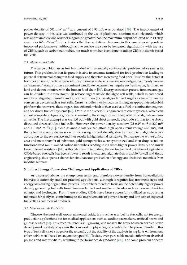
It has been shown that the functionalized multi-walled carbon nanotubes (fMWCNTs), whichcontain a lot of –COOH and –OH groups, are hydrophilic and prevent the aggregation of nanoparticlesduring activation and thermal treatment processes, thus maintain high total active surface area [66,67].The use of fMWCNTs as supporting matrix resulted in higher catalytic performance, indicated by~150–200 mV negative shifts of oxidation peaks compared to that from bare gold electrodes, meaningthat relatively less activation energy is needed to overcome. Furthermore, different monosaccharidesexhibit different oxidation peaks in terms of position, shape, and current intensity [66]. Since thestructures of these monosaccharides differ only at the orientation of –OH groups on C2 and C3,the different oxidation potentials suggest that the specific structural attachments of intermediatecomplexes on gold nanoparticles decorated on fMWCNTs (AuNPs/f-MWCNTs) induce differentactivated energies for further oxidization. By dispersing AuNPs on fMWCNTs, the gold surface ismuch more active and respond more sensitively to the change in –OH orientation, leading to higheroxidation current density than that of bare gold electrode. Consequently, the power density generatedfrom AuNPs/fMWCNTs-based FCs is more than twice of that from Au-based FCs (Figure 5). With thisapproach, two homemade small (2 mL in volume, Figure 6) glucose or fructose fuel cells could runa led lamp that requires a working voltage of 2 V [66,68].
Sensors 2017, 17, 2587 9 of 21
problems, CBNs, mainly functionalized carbon nanotubes and graphene-based materials were used as the catalytic backbone for noble nanoparticles to (i) increase the active surface area; (ii) decrease noble metal loading; leading to lower cost and (iii) increase stability of catalyst by fine-tuning catalytic mechanism [65].
It has been shown that the functionalized multi-walled carbon nanotubes (fMWCNTs), which contain a lot of –COOH and –OH groups, are hydrophilic and prevent the aggregation of nanoparticles during activation and thermal treatment processes, thus maintain high total active surface area [66,67]. The use of fMWCNTs as supporting matrix resulted in higher catalytic performance, indicated by ~150–200 mV negative shifts of oxidation peaks compared to that from bare gold electrodes, meaning that relatively less activation energy is needed to overcome. Furthermore, different monosaccharides exhibit different oxidation peaks in terms of position, shape, and current intensity [66]. Since the structures of these monosaccharides differ only at the orientation of –OH groups on C2 and C3, the different oxidation potentials suggest that the specific structural attachments of intermediate complexes on gold nanoparticles decorated on fMWCNTs (AuNPs/f-MWCNTs) induce different activated energies for further oxidization. By dispersing AuNPs on fMWCNTs, the gold surface is much more active and respond more sensitively to the change in –OH orientation, leading to higher oxidation current density than that of bare gold electrode. Consequently, the power density generated from AuNPs/fMWCNTs-based FCs is more than twice of that from Au-based FCs (Figure 5). With this approach, two homemade small (2 mL in volume, Figure 6) glucose or fructose fuel cells could run a led lamp that requires a working voltage of 2 V [66,68].
Figure 5. Power density of monosaccharide-based fuel cells using AuNPs/fMWCNTs as anodic catalyst in comparison with bare Au electrode. Reprinted with permission from ref. [66]. Copyright 2011, Elservier.
Figure 5. Power density of monosaccharide-based fuel cells using AuNPs/fMWCNTs as anodiccatalyst in comparison with bare Au electrode. Reprinted with permission from ref. [66].Copyright 2011, Elservier.

Sensors 2017, 17, 2587 10 of 21
Sensors 2017, 17, 2587 10 of 21
Figure 6. (A) Air-glucose fuel cell prototype and (B) its performance in terms of polarization and power density. Glucose concentration was 0.4 M in 0.3 M NaOH and 0.1 M PBS; temperature was 25 ° C. The working voltage of the LED lamp was 2 V. Reprinted with permission from ref. [66]. Copyright 2011, Elsevier.
Carbon-based nanomaterials are not only excellent supports for noble catalytic metals, but also for enzymatic systems in enzymatic-based FCs (EFCs). Different from the direct oxidation of fuels on catalytic metal surface, the active centers in enzymes are buried and insulated by the protein shell, leading to detrimental effect of electron transfer between the enzyme and the current collector. Based on electron transfer mechanism, EFCs can be divided into two types: Direct electron transfer (DET) and mediator electron transfer (MET). DET requires both proper orientation of an enzyme, as well as the distance between the active center as electron donor and the electrode as electron acceptor. This distance has to be within ~2 nm. Since the electron transfer rate depends exponentially on this distance, it is commonly believed that MET which uses mediator cofactor to shuttle electrons from enzyme to electrode, might be the better choice of the two. However, CBNs have altered this mindset. CNTs, graphene-based materials and most recently carbon nanodots (CNDs) have been used to create direct “wiring” systems since their size is quite close to that of enzymes [69–74]. For instance, Ivnitski et al. demonstrated direct glucose oxidation on glucose oxidase (GOx) immobilized on CNT-modified porous bioanode as well as the direct reduction of oxygen with laccase [70]. Although direct enzymatic oxidation of glucose is still highly debated and the mechanism is not yet clearly proven, the fact that glucose oxidase is able to simultaneously undergo DET with the electrode and to retain its catalytic activity has been confirmed by the cyclic voltammetry study of the GOx immobilized on the surface of CNTs modified electrodes in the absence and in the presence of glucose. This GOx–CNTs-based membraneless FC achieved an open circuit potential of ~400 mV vs Ag/AgCl. Graphene was used in the same way as CNTs to co-immobilize with GOx on anode and bilirubin oxidase (BOD) for cathodic catalyst, resulting in a maximum power density of about 24.3 ± 4 μW cm−2. This is nearly three times greater than that of the SWCNT-based biofuel cell [71], and the performance of the graphene biofuel cell lasted for a week. Instead of graphene sheets, Zheng and colleagues made use of nanographene platelets (NGPs) to immobilize GOx and BOD, and achieved a maximum power density of 57.8 μW cm−2 [73]. A higher open circuit potential (0.93 V) and a maximum power density of 40.8 μW cm−2 (at 0.41V) were achieved recently by Zhao and colleagues with DET of GOx and BOD at Carbon Nanodots (CNDs) electrodes [72]. This CND-based glucose FCs surpassed the power density could be achieved from MET-type BFCs in which an oxygen independent Pyrroloquinoline Quinone (PQQ)–GDH–MWCNT-electrode coupled with a
Figure 6. (A) Air-glucose fuel cell prototype and (B) its performance in terms of polarization andpower density. Glucose concentration was 0.4 M in 0.3 M NaOH and 0.1 M PBS; temperature was25 ◦C. The working voltage of the LED lamp was 2 V. Reprinted with permission from ref. [66].Copyright 2011, Elsevier.
Carbon-based nanomaterials are not only excellent supports for noble catalytic metals, butalso for enzymatic systems in enzymatic-based FCs (EFCs). Different from the direct oxidationof fuels on catalytic metal surface, the active centers in enzymes are buried and insulated by theprotein shell, leading to detrimental effect of electron transfer between the enzyme and the currentcollector. Based on electron transfer mechanism, EFCs can be divided into two types: Direct electrontransfer (DET) and mediator electron transfer (MET). DET requires both proper orientation ofan enzyme, as well as the distance between the active center as electron donor and the electrodeas electron acceptor. This distance has to be within ~2 nm. Since the electron transfer rate dependsexponentially on this distance, it is commonly believed that MET which uses mediator cofactor toshuttle electrons from enzyme to electrode, might be the better choice of the two. However, CBNshave altered this mindset. CNTs, graphene-based materials and most recently carbon nanodots(CNDs) have been used to create direct “wiring” systems since their size is quite close to that ofenzymes [69–74]. For instance, Ivnitski et al. demonstrated direct glucose oxidation on glucose oxidase(GOx) immobilized on CNT-modified porous bioanode as well as the direct reduction of oxygenwith laccase [70]. Although direct enzymatic oxidation of glucose is still highly debated and themechanism is not yet clearly proven, the fact that glucose oxidase is able to simultaneously undergoDET with the electrode and to retain its catalytic activity has been confirmed by the cyclic voltammetrystudy of the GOx immobilized on the surface of CNTs modified electrodes in the absence and in thepresence of glucose. This GOx–CNTs-based membraneless FC achieved an open circuit potential of~400 mV vs Ag/AgCl. Graphene was used in the same way as CNTs to co-immobilize with GOx onanode and bilirubin oxidase (BOD) for cathodic catalyst, resulting in a maximum power density ofabout 24.3 ± 4 µW cm−2. This is nearly three times greater than that of the SWCNT-based biofuelcell [71], and the performance of the graphene biofuel cell lasted for a week. Instead of graphene sheets,Zheng and colleagues made use of nanographene platelets (NGPs) to immobilize GOx and BOD, andachieved a maximum power density of 57.8 µW cm−2 [73]. A higher open circuit potential (0.93 V) anda maximum power density of 40.8 µW cm−2 (at 0.41V) were achieved recently by Zhao and colleagueswith DET of GOx and BOD at Carbon Nanodots (CNDs) electrodes [72]. This CND-based glucose FCssurpassed the power density could be achieved from MET-type BFCs in which an oxygen independentPyrroloquinoline Quinone (PQQ)–GDH–MWCNT-electrode coupled with a BOD–MWCNT-electrodewere used (23 µW cm−2). The success of CBNs and enzymatic systems has meant that the use of noblemetals could be avoided, thus reducing significantly the cost of the final product. However, when the

Sensors 2017, 17, 2587 11 of 21
power density is the target, the composite of CBN with noble metals increases power density evenmore. By anchoring AuNPs on reduced graphene oxide, followed by electrochemical polymerizationof neutral red (RGO/AuNPs/PNR) before drop-casting GOx, the power density gained from thiselectrode was increased up to 176 µW cm−2 [74]. Zebda and colleagues, thus far, have reported thehighest power density. In their work, glucose oxidase and laccase were mechanically compressedinto CNT disks [75]. This led to homogenous dispersion of biomolecules within the CNT supportingmatrix. However, in the presence of oxygen within the non-wired GOx matrix, a possible formation ofhydrogen peroxide may degrade GOx performance. To overcome this problem, catalase was added tothe GOx–NT mixture before compression to decompose H2O2. This improved mediatorless glucosebiofuel cell generated a high power density up to 1.3 mW cm−2 and achieved an open circuit voltageof 0.95 V. Moreover, the fuel cell performance remained stable for a month and delivered 1 mW cm−2
power density under physiological conditions (5 × 10⁻³ M glucose, pH 7).When using for MET-based glucose fuel cell, CNTs-based FCs achieved up to 740 µW cm−2 in
the presence of 0.015 M glucose, which is tenfold higher than that of the same catalytic system usingtraditional carbon fiber supporting matrix [76]. Kim et al. recently reported a simple method forsimultaneous CNT dispersion and sequential enzyme adsorption, precipitation, and crosslinking thatresulted in 7.5 times higher power output than that from the covalently-attached GOx on acid-treatedCNTs and GOx activity remained stable for 270 days [77].
3.2. Bio-Ethanol Fuel Cell
Bioethanol is now practically being used as a blend or fossil petrol substitute. For example, inthe USA the use of ethanol as a blended component has increased dramatically from about 1.7 billiongallons in 2001 to about 14.4 billion in 2016 [78]. However, the “food-versus-fuel” issue is stillproblematic because ethanol is mostly produced from edible feedstock such as corn. Researchers aretherefore, targeting non-edible feedstock including waste from agriculture and forestry and brownmacroalgae to produce second generation of bioethanol [79,80]. This is done by fermentation followedby distillation and drying process. Burning ethanol in the way it has been done with fossil fuel,however, is not the best and “green” way to utilize energy from ethanol. Direct ethanol fuel cells(DEFCs) have been reviewed in detail by Kamarudin et al. and Badwal et al., revealing the currentchallenges, developments and applications of DEFCs [81,82]. However, there is lack of informationabout CBNs’ studies. An effective yet durable catalytic system for ethanol oxidation reaction in PEMFChas been the target of research and could be divided into two different categories. First, the focuswas on understanding the catalytic mechanisms; increasing the durability and decreasing the cost ofnoble-based materials by making alloys such as Sn/SnO2/Pt. One of the main advantages of usingthese non-noble metal/metal oxide is to create –OH absorption, thus enhancing the removal of COadand other poisonous species out of Pt surface (Figure 7). In some special cases, such as Pt–S—Rh/Ccatalysts, it has been reported that C–C cleavage could be achieved, producing CO2 as final productinstead of acetic acid [83].Sensors 2017, 17, 2587 12 of 21
Figure 7. Ethanol oxidation reaction pathway.
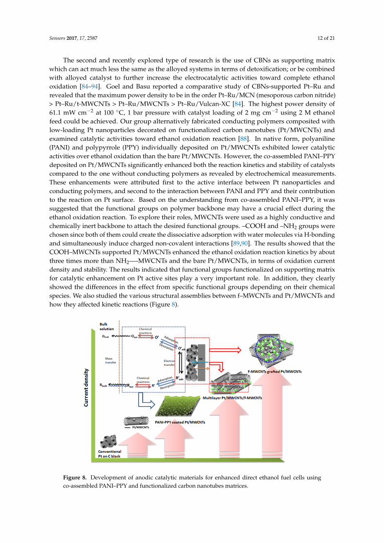
The second and recently explored type of research is the use of CBNs as supporting matrix which can act much less the same as the alloyed systems in terms of detoxification; or be combined with alloyed catalyst to further increase the electrocatalytic activities toward complete ethanol oxidation [84–94]. Goel and Basu reported a comparative study of CBNs-supported Pt–Ru and revealed that the maximum power density to be in the order Pt–Ru/MCN (mesoporous carbon nitride) > Pt–Ru/t-MWCNTs > Pt–Ru/MWCNTs > Pt–Ru/Vulcan-XC [84]. The highest power density of 61.1 mW cm−2 at 100 °C, 1 bar pressure with catalyst loading of 2 mg cm−2 using 2 M ethanol feed could be achieved. Our group alternatively fabricated conducting polymers composited with low-loading Pt nanoparticles decorated on functionalized carbon nanotubes (Pt/MWCNTs) and examined catalytic activities toward ethanol oxidation reaction [88]. In native form, polyaniline (PANI) and polypyrrole (PPY) individually deposited on Pt/MWCNTs exhibited lower catalytic activities over ethanol oxidation than the bare Pt/MWCNTs. However, the co-assembled PANI–PPY deposited on Pt/MWCNTs significantly enhanced both the reaction kinetics and stability of catalysts compared to the one without conducting polymers as revealed by electrochemical measurements. These enhancements were attributed first to the active interface between Pt nanoparticles and conducting polymers, and second to the interaction between PANI and PPY and their contribution to the reaction on Pt surface. Based on the understanding from co-assembled PANI–PPY, it was suggested that the functional groups on polymer backbone may have a crucial effect during the ethanol oxidation reaction. To explore their roles, MWCNTs were used as a highly conductive and chemically inert backbone to attach the desired functional groups. –COOH and –NH2 groups were chosen since both of them could create the dissociative adsorption with water molecules via H-bonding and simultaneously induce charged non-covalent interactions [89,90]. The results showed that the COOH–MWCNTs supported Pt/MWCNTs enhanced the ethanol oxidation reaction kinetics by about three times more than NH2––MWCNTs and the bare Pt/MWCNTs, in terms of oxidation current density and stability. The results indicated that functional groups functionalized on supporting matrix for catalytic enhancement on Pt active sites play a very important role. In addition, they clearly showed the differences in the effect from specific functional groups depending on their chemical species. We also studied the various structural assemblies between f–MWCNTs and Pt/MWCNTs and how they affected kinetic reactions (Figure 8).
Figure 7. Ethanol oxidation reaction pathway.
Sensors 2017, 17, 2587 12 of 21
The second and recently explored type of research is the use of CBNs as supporting matrixwhich can act much less the same as the alloyed systems in terms of detoxification; or be combinedwith alloyed catalyst to further increase the electrocatalytic activities toward complete ethanoloxidation [84–94]. Goel and Basu reported a comparative study of CBNs-supported Pt–Ru andrevealed that the maximum power density to be in the order Pt–Ru/MCN (mesoporous carbon nitride)> Pt–Ru/t-MWCNTs > Pt–Ru/MWCNTs > Pt–Ru/Vulcan-XC [84]. The highest power density of61.1 mW cm−2 at 100 ◦C, 1 bar pressure with catalyst loading of 2 mg cm−2 using 2 M ethanolfeed could be achieved. Our group alternatively fabricated conducting polymers composited withlow-loading Pt nanoparticles decorated on functionalized carbon nanotubes (Pt/MWCNTs) andexamined catalytic activities toward ethanol oxidation reaction [88]. In native form, polyaniline(PANI) and polypyrrole (PPY) individually deposited on Pt/MWCNTs exhibited lower catalyticactivities over ethanol oxidation than the bare Pt/MWCNTs. However, the co-assembled PANI–PPYdeposited on Pt/MWCNTs significantly enhanced both the reaction kinetics and stability of catalystscompared to the one without conducting polymers as revealed by electrochemical measurements.These enhancements were attributed first to the active interface between Pt nanoparticles andconducting polymers, and second to the interaction between PANI and PPY and their contributionto the reaction on Pt surface. Based on the understanding from co-assembled PANI–PPY, it wassuggested that the functional groups on polymer backbone may have a crucial effect during theethanol oxidation reaction. To explore their roles, MWCNTs were used as a highly conductive andchemically inert backbone to attach the desired functional groups. –COOH and –NH2 groups werechosen since both of them could create the dissociative adsorption with water molecules via H-bondingand simultaneously induce charged non-covalent interactions [89,90]. The results showed that theCOOH–MWCNTs supported Pt/MWCNTs enhanced the ethanol oxidation reaction kinetics by aboutthree times more than NH2—-MWCNTs and the bare Pt/MWCNTs, in terms of oxidation currentdensity and stability. The results indicated that functional groups functionalized on supporting matrixfor catalytic enhancement on Pt active sites play a very important role. In addition, they clearlyshowed the differences in the effect from specific functional groups depending on their chemicalspecies. We also studied the various structural assemblies between f–MWCNTs and Pt/MWCNTs andhow they affected kinetic reactions (Figure 8).Sensors 2017, 17, 2587 13 of 21
Figure 8. Development of anodic catalytic materials for enhanced direct ethanol fuel cells using co-assembled PANI–PPY and functionalized carbon nanotubes matrices.
Instead of CNTs, graphene oxide was exploited and successfully applied as matrix to attach noble metals such as Pt and Pd [85]. Kumar et al. reported a simple procedure to synthesize large-scale perforated graphene oxide nanosheets-Pd hybrids (Pd–FP–rGONSs) using microwave irradiation. The prepared Pd–FP–rGONSs were composed of a large amount of structural surface defects which created porosity inside the nanosheets, leading to lower charge transfer resistance and negative oxidation peak shifts. As a result, Pd–FP–rGONSs performed much better in terms of current density (10.2 mA cm−2) than Pd/MWCNTs (0.4 mA cm−2) at the same initial ethanol concentration. To date, however, there is no published work yet on the final prototype and its power density of DEFCs, which use graphene oxide-based catalyst.
Similar to other types of biofuel cells, ethanol biofuel cells can be divided into two main types: Enzyme-based and microbial-based FCs. The former one uses alcohol dehydrogenase to catalyze the oxidation of ethanol, and faces similar electron transfer problems as the above-discussed enzyme-based glucose BFCs. Additionally, the use of NAD-dependent enzymes such as ADH needs to regenerate NAD+ species and restore the enzyme cycle. Last but not least is the high over potential of NADH (more than 1 V) and the passivation of the electrode surface such as noble metals. To overcome this problem, the electrode surface was modified with MWCNTs to mediate the electrocatalytic oxidation of NAD-dependent enzymes [91], decreasing the high overvoltage for NADH oxidation of 0.16 V [92]. Besides decreasing the over voltage of NAD+/NADH system, modification of electrode by CNTs has been proved to enhance the efficiency of enzyme in power density and electron transfer kinetics [93]. Gouranlou et al. recently reported an ethanol–oxygen biofuel cell design in which PDDA/ADH/PDDA/HOOC–MWCNTs/PMG/GC and PDDA/Lac/PDDA/HOOC-MWCNTs/PMG/Gr operated as bioanode and biocathode, respectively (PDDA and PMG stand for polydiallyldimethylammonium chloride and polymethylene green, respectively). HOOC–MWCNTs beside PDDA has been proved to provide a suitable microenvironment to preserve the activity of ADH and laccase [80]. In the optimized condition, this BFC produced a power density of 3.98 mW cm−2 with the OCP of 0.504V. With the use of COOH–MWCNTs as cathodic catalyst, the power density was increased much more than that of traditional Pt/C electrode, which could achieve only 1.713 mW cm−2 and OCP of 0.281 V [94].
3.3. Bio-Hydrogen Fuel Cell
Among all types of fuel cells, the hydrogen fuel cell is the most successful one in terms of power density, hence high possibilities for wide application. Although a hydrogen fuel cell is a zero
Figure 8. Development of anodic catalytic materials for enhanced direct ethanol fuel cells usingco-assembled PANI–PPY and functionalized carbon nanotubes matrices.

Sensors 2017, 17, 2587 13 of 21
Instead of CNTs, graphene oxide was exploited and successfully applied as matrix to attach noblemetals such as Pt and Pd [85]. Kumar et al. reported a simple procedure to synthesize large-scaleperforated graphene oxide nanosheets-Pd hybrids (Pd–FP–rGONSs) using microwave irradiation.The prepared Pd–FP–rGONSs were composed of a large amount of structural surface defects whichcreated porosity inside the nanosheets, leading to lower charge transfer resistance and negativeoxidation peak shifts. As a result, Pd–FP–rGONSs performed much better in terms of current density(10.2 mA cm−2) than Pd/MWCNTs (0.4 mA cm−2) at the same initial ethanol concentration. To date,however, there is no published work yet on the final prototype and its power density of DEFCs, whichuse graphene oxide-based catalyst.
Similar to other types of biofuel cells, ethanol biofuel cells can be divided into two maintypes: Enzyme-based and microbial-based FCs. The former one uses alcohol dehydrogenase tocatalyze the oxidation of ethanol, and faces similar electron transfer problems as the above-discussedenzyme-based glucose BFCs. Additionally, the use of NAD-dependent enzymes such as ADHneeds to regenerate NAD+ species and restore the enzyme cycle. Last but not least is thehigh over potential of NADH (more than 1 V) and the passivation of the electrode surfacesuch as noble metals. To overcome this problem, the electrode surface was modified withMWCNTs to mediate the electrocatalytic oxidation of NAD-dependent enzymes [91], decreasingthe high overvoltage for NADH oxidation of 0.16 V [92]. Besides decreasing the over voltage ofNAD+/NADH system, modification of electrode by CNTs has been proved to enhance the efficiencyof enzyme in power density and electron transfer kinetics [93]. Gouranlou et al. recently reportedan ethanol–oxygen biofuel cell design in which PDDA/ADH/PDDA/HOOC–MWCNTs/PMG/GCand PDDA/Lac/PDDA/HOOC-MWCNTs/PMG/Gr operated as bioanode and biocathode,respectively (PDDA and PMG stand for polydiallyldimethylammonium chloride and polymethylenegreen, respectively). HOOC–MWCNTs beside PDDA has been proved to provide a suitablemicroenvironment to preserve the activity of ADH and laccase [80]. In the optimized condition,this BFC produced a power density of 3.98 mW cm−2 with the OCP of 0.504V. With the use ofCOOH–MWCNTs as cathodic catalyst, the power density was increased much more than that oftraditional Pt/C electrode, which could achieve only 1.713 mW cm−2 and OCP of 0.281 V [94].
3.3. Bio-Hydrogen Fuel Cell
Among all types of fuel cells, the hydrogen fuel cell is the most successful one in terms of powerdensity, hence high possibilities for wide application. Although a hydrogen fuel cell is a zero emissionenergy device, it is still not a true “green” option since the hydrogen production is mostly fromlarge-scale natural gas reforming processes. Furthermore, storage and transportation issues stillpresent problems for the commercialization of hydrogen as a fuel [95]. To solve the productionproblem, much works have been devoted to developing bio-H2 production technologies basedon either “classical” metabolically engineered microorganism or mixed bacterial consortia undercontrolled nutrient condition to modify gene expression towards increased H2 production [96–100].These approaches enable H2 production from not only pure biomass-based fuel such as glucose butalso raw and complex materials such as starch or wastewater. On the other hand, direct connection ofbiohydrogen reactors and onsite energy conversion devices could be an answer to storage and transportproblems. Most recently, Wenzel and colleagues reported a MFC coupled to biohydrogen reactor asa feasible technology to increase energy yield from cheese whey. Effluent from dark fermentation ofcheese whey was successfully used to produce a maximal power density of 439 mW m−2 [100].
Unfortunately, hydrogen production processes from biomass often involve the use ofmicroorganisms, which require voluminous bioreactors to ensure a sufficient production rate; anda filter to remove unwanted gases. Researchers so far have tried to integrate the whole fermentationsystem and a proton-exchange-membrane fuel cell (PEMFC) for electricity generation [101–104].Still much extra energy is needed to maintain the bioreactor, filter, and the pumping system. In ourgroup, we demonstrated a compact single chamber-based fuel cell that changes the anode chamber of

Sensors 2017, 17, 2587 14 of 21
the hydrogen PEMFC to an anaerobic fermentation bioreactor (Figure 9). This combination greatlyreduced the external energy needed for maintaining the bioreactor, condenser and/or filter, for storinggases under high pressure (optional) and for the humidifier before pumping the hydrogen into thePEMFC. Consequently, the total useful energy from the whole system increased [105,106].
Sensors 2017, 17, 2587 14 of 21
emission energy device, it is still not a true “green” option since the hydrogen production is mostly from large-scale natural gas reforming processes. Furthermore, storage and transportation issues still present problems for the commercialization of hydrogen as a fuel [95]. To solve the production problem, much works have been devoted to developing bio-H2 production technologies based on either “classical” metabolically engineered microorganism or mixed bacterial consortia under controlled nutrient condition to modify gene expression towards increased H2 production [96–100]. These approaches enable H2 production from not only pure biomass-based fuel such as glucose but also raw and complex materials such as starch or wastewater. On the other hand, direct connection of biohydrogen reactors and onsite energy conversion devices could be an answer to storage and transport problems. Most recently, Wenzel and colleagues reported a MFC coupled to biohydrogen reactor as a feasible technology to increase energy yield from cheese whey. Effluent from dark fermentation of cheese whey was successfully used to produce a maximal power density of 439 mW m−2 [100].
Unfortunately, hydrogen production processes from biomass often involve the use of microorganisms, which require voluminous bioreactors to ensure a sufficient production rate; and a filter to remove unwanted gases. Researchers so far have tried to integrate the whole fermentation system and a proton-exchange-membrane fuel cell (PEMFC) for electricity generation [101–104]. Still much extra energy is needed to maintain the bioreactor, filter, and the pumping system. In our group, we demonstrated a compact single chamber-based fuel cell that changes the anode chamber of the hydrogen PEMFC to an anaerobic fermentation bioreactor (Figure 9). This combination greatly reduced the external energy needed for maintaining the bioreactor, condenser and/or filter, for storing gases under high pressure (optional) and for the humidifier before pumping the hydrogen into the PEMFC. Consequently, the total useful energy from the whole system increased [105,106].
Figure 9. Fuel cell components and the assembly of hydrogen fuel cell with bioreactor.
However, due to direct attachment of bioreactor to anode, unwanted gases and microorganisms in the anode chamber could enter the pores of the electrodes via water vapor, resulting in a significant reduction of gas dispersion inside the catalyst layers and lower catalytic activity. To address this problem, doped polyaniline (PANI) nanofibre-based composites with Pt/fMWNTs were used instead of traditional PtNPs on carbon black to achieve much higher conductivity, higher catalytic activity under humid condition, more access to the gases resulting from a three-dimensional structure with more active sites, and more resistance to corrosion. The hybrid
Figure 9. Fuel cell components and the assembly of hydrogen fuel cell with bioreactor.
However, due to direct attachment of bioreactor to anode, unwanted gases and microorganismsin the anode chamber could enter the pores of the electrodes via water vapor, resulting in a significantreduction of gas dispersion inside the catalyst layers and lower catalytic activity. To address thisproblem, doped polyaniline (PANI) nanofibre-based composites with Pt/fMWNTs were used instead oftraditional PtNPs on carbon black to achieve much higher conductivity, higher catalytic activity underhumid condition, more access to the gases resulting from a three-dimensional structure with moreactive sites, and more resistance to corrosion. The hybrid structure was made in two ways: multilayeredand core-shell. The maximum power density from the former (733 mW m−2 of PANI/Pt/fMWNTs)was more than twice compared to that of the later one (352.75 mW m−2 of Pt/fMWNTs@PANI).The enhanced performance in case of multilayer structure was made possible by the active contactbetween the PANI nanofiber layer and Pt/fMWNTs that facilitates selective hydrogen absorptionand increases conductivity at high humidity [106]. The power density of this biohydrogen fuel cellwas much higher than the MFCs using CNTs/PANI composite as anode material (42 mW m−2) inQiao et al. [107], and comparable with other single chambered, glucose-fed mediatorless MFCs usingE. coli or mixed anaerobic consortia [108–112].
Another approach is using H2/O2 biofuel cells, in which hydrogenase is used as anodic catalystand multicopper oxidase as cathodic catalyst. It is estimated that the maximum current densitywould be 1 mA cm−2, when the enzyme forms an electrocatalytically active monolayer on a planarelectrode. Thus, three-dimensionally structured CBNs have been explored to increase enzyme loadingand efficient orientation of enzyme towards enhanced electron transfer rate. The power density ofFCs has reached 8 mW cm−2 and the current density is up to 10 mA cm−2 [113–117]. The fuel inthese cases was mostly pure H2 or mixture of pure H2 and O2 or air, which is different from biogasgenerated directly from biohydrogen reactors, and therefore out of our scope in this mini review.Nevertheless the development of H2/O2 biofuel cells towards the use of biomass-generated hydrogen

Sensors 2017, 17, 2587 15 of 21
could be a promising future study. Details about recent studies on CBNs in H2/O2 biofuel cells werethoroughly reported in a review article by Mazurenko et al [118].
4. Concluding Remarks
It is obvious that the future of biofuels as alternative to fossil fuel requires technologicaldevelopment of efficient but low-cost biofuel-based energy conversion devices. Biofuel-fed fuelcell, which can work at low temperature, are non-toxic, have low carbon emissions, and utilizea wide range of biofuel sources in both pure and non-pure forms (e.g., from wastewater), is thereforea promising technology. However, there are still many challenges that need to be overcome beforereaching practical and commercial states. As presented above, although the direct biofuel-fed fuel cellsgenerate electricity directly from main biomass components such as cellulose, starch, and alginate,the power density is too low, thus the only possible application is coupling with the wastewatertreatment process to extract energy simultaneously with the degradation of biomass as organic wastes.Along with the development of breakdown technology, many more efforts have been devoted todevelop fuel cells that indirectly extract energy from biomass i.e., from secondary fuels such asmonosaccharides, bioethanol, and biohydrogen. So far, the power density of such biofuel-fed fuelcells could reach the demand of portable devices but fuel cell fabrication cost and its durabilityare still the main hurdles. For both direct and indirect biofuel-fed fuel cells, the main challengesare high cost yet low durability of catalytic systems, resulting in limited fuel cell performance.To replace expensive noble metal-based catalysts, carbon-based nanomaterials have been exploredand contributed significantly to the improvement of fuel cell performance. When used as supportingmatrix, carbon-based nanomaterials such as graphene, CNTs, and their functionalized materials createa 3-D architecture for anchoring metal nanoparticles/microorganism/enzyme with much highersurface area to volume ratio, enhanced electrolyte diffusion and simultaneously act as electron transfernetwork. Furthermore, functionalized carbon-based nanomaterials have been proven to be involvedin removing toxic intermediates on the embedded nanoparticles in case of metallic catalysts andenhanced immobilization and stabilization of enzymatic systems, resulting in improvement of catalyticdurability. As a result of using CBNs, the power density of biofuel-fed FCs increased from nW to mWcm−2, open circuit potential increased to more than 1 V (fucose and glucose FCs) and life-time of fuelcell performance was significantly extended. Based on these achievements, future research trendscould be seen targeting (i) deeper understanding and optimizing current successful CBNs for each typeof biofuel-fed FCs; and (ii) discovery of new materials such as composites of well-established and/orentirely new metal-free CBNs towards low-cost but long-term large scale practical applications.
Author Contributions: The paper is a review articles drawn from our group and other groups, as shown by thecitations. H.Q.L., M.C.V. and E.T. discussed the subject matter, H.Q.L drafted the paper, M.C.V. revised the paper.
Conflicts of Interest: The authors declare no conflict of interest.
References
1. Demirbas, A. Biofuels: Securing the Planet’s Future Energy Needs, 1st ed.; Springer: London, UK, 2009;pp. 231–260, ISBN 10-1848820100.
2. Gaurav, N.; Sivasankari, S.; Kiran, G.S.; Ninawea, A.; Selvin, J. Utilization of bioresources for sustainablebiofuels: A Review. Renew. Sustain. Energy Rev. 2017, 73, 205–214. [CrossRef]
3. Somerville, C.; Youngs, H.; Taylor, C.; Davis, S.C.; Long, S.P. Feedstocks for Lignocellulosic Biofuels. Science2010, 329, 790–792. [CrossRef] [PubMed]
4. Chaemchuen, S.; Zhou, K.; Verpoort, F. From Biogas to Biofuel: Materials Used for Biogas Cleaning toBiomethane. ChemBioEng Rev. 2016, 3, 250–265. [CrossRef]
5. Abatzoglou, N.; Boivin, S. A review of biogas purification processes. Biofuels Bioprod. Biorefin. 2009, 3, 42–71.[CrossRef]
6. Harris, D.; DeBolt, S. Synthesis, regulation and utilization of lignocellulosic biomass. Plant Biotechnol. J. 2010,8, 244–262. [CrossRef] [PubMed]

Sensors 2017, 17, 2587 16 of 21
7. Harris, D.; Stork, J.; Debolt, S. Genetic modification in cellulose-synthase reduces crystallinity and improvesbiochemical conversion to fermentable sugar. Glob. Chang. Biol. Bioenergy 2009, 1, 51–61. [CrossRef]
8. Lynd, L.R.; Weimer, P.J.; van Zyl, W.H.; Pretorius, I.S. Microbial Cellulose Utilization: Fundamentals andBiotechnology. Microbiol. Mol. Biol. Rev. 2002, 66, 506–577. [CrossRef] [PubMed]
9. Olson, D.G.; McBride, J.E.; Shaw, A.J.; Lynd, L.R. Recent progress in consolidated bioprocessing.Curr. Opin. Biotechnol. 2012, 23, 396–405. [CrossRef] [PubMed]
10. Chung, D.; Cha, M.; Guss, A.M.; Westpheling, J. Direct conversion of plant biomass to ethanol by engineeredCaldicellulosiruptor bescii. Proc. Natl. Acad. Sci. USA 2014, 111, 8931–8936. [CrossRef] [PubMed]
11. Cotta, M.A. Ethanol production from lignocellulosic biomass by recombinant Escherichia coli strain FBR5.Bioengineered 2012, 3, 197–202. [CrossRef] [PubMed]
12. Wargacki, A.J.; Leonard, E.; Win, M.N.; Regitsky, D.D.; Santos, C.N.S.; Kim, P.B.; Cooper, S.R.; Raisner, R.M.;Herman, A.; Sivitz, A.B.; et al. An engineered microbial platform for direct biofuel production from brownmacroalgae. Science 2012, 335, 308–313. [CrossRef] [PubMed]
13. Ranganathan, A.; Smith, O.P.; Youssef, N.H.; Struchtemeyer, C.G.; Atiyeh, H.K.; Elshahed, M.S.Utilizing Anaerobic Fungi for Two-stage Sugar Extraction and Biofuel Production from LignocellulosicBiomass. Front. Microbiol. 2017, 8, 1–10. [CrossRef] [PubMed]
14. You, C.; Chen, H.; Myung, S.; Sathitsuksanoh, N.; Ma, H.; Zhang, X.-Z.; Li, J.; Zhang, Y.-H.P.Enzymatic transformation of nonfood biomass to starch. Proc. Natl. Acad. Sci. USA 2013, 110, 7182–7187.[CrossRef] [PubMed]
15. Sugano, Y.; Vestergaard, M.; Yoshikawa, H.; Saito, M.; Tamiya, E. Direct Electrochemical Oxidation ofCellulose: A Cellulose-Based Fuel Cell System. Electroanalysis 2010, 22, 1688–1694. [CrossRef]
16. Aricò, A.S.; Bruce, P.; Scrosati, B.; Tarascon, J.M.; van Schalkwijk, W. Nanostructured materials for advancedenergy conversion and storage devices. Nat. Mater. 2005, 4, 366–377. [CrossRef] [PubMed]
17. Antolini, E. Pt-Ni and Pt-M-Ni (M = Ru, Sn) Anode Catalysts for Low-Temperature Acidic Direct AlcoholFuel Cells: A Review. Energies 2017, 10, 42. [CrossRef]
18. Zhang, J.; Xia, Z.; Dai, L. Carbon-based electrocatalysts for advanced energy conversion and storage. Sci. Adv.2015, 1, e1500564. [CrossRef] [PubMed]
19. Guo, S.; Zhang, S.; Wu, L.; Sun, S. Co/CoO Nanoparticles Assembled on Graphene for ElectrochemicalReduction of Oxygen. Angew. Chem. Int. Ed. 2012, 51, 11770–11773. [CrossRef] [PubMed]
20. Deng, D.; Yu, L.; Chen, X.; Wang, G.; Jin, L.; Pan, X.; Deng, J.; Sun, G.; Bao, X. Iron encapsulated withinpod-like carbon nanotubes for oxygen reduction reaction. Angew. Chem. Int. Ed. 2013, 52, 371–375. [CrossRef][PubMed]
21. Appleby, A.; Foulkes, F. Fuel Cell Handbook; Van Nostrand Reinhold: New York, NY, USA, 1989.22. EG&G Technical Services, Inc.; Science Application International Corporation. Fuel Cell Handbook, 6th ed.;
U.S. Department of Energy, National Energy Technology Laboratory: Albany, OR, USA, 2002.23. Kordesch, K.; Simader, G. Fuel Cells and Their Applications; Wiley-VCH: Weinheim, Germany, 1996.24. Pagliaro, M.; Konstandopoulos, A.G. Chapter 1: Hydrogen and solar hydrogen. In Solar Hydrogen: Fuel
of the Future; Pagliaro, M., Konstandopoulos, A.G., Eds.; Royal Society of Chemistry: London, UK, 2012;pp. 1–39, ISBN 978-1-84973-195-9.
25. Iijima, S. Helical microtubules of graphitic carbon. Nature 1991, 354, 56–58. [CrossRef]26. Novoselov, K.S.; Geim, A.K.; Morozov, S.V. Electric field effect in atomically thin carbon films. Science 2004,
306, 666–669. [CrossRef] [PubMed]27. Cha, C.; Shin, S.R.; Annabi, N.; Dokmeci, M.R.; Khademhosseini, A. Carbon-Based Nanomaterials:
Multi-Functional Materials for Biomedical Engineering. ACS Nano 2013, 7, 2891–2897. [CrossRef] [PubMed]28. Lee, C.; Wei, X.; Kysar, J.W.; Hone, J. Measurement of the elastic properties and intrinsic strength of
mono-layer graphene. Science 2008, 321, 385–388. [CrossRef] [PubMed]29. Baughman, R.H.; Zakhidov, A.A.; de Heer, W.A. Carbon Nanotubes—The Route Toward Applications.
Science 2002, 297, 787–792. [CrossRef] [PubMed]30. Sawant, S.Y.; Han, T.H.; Cho, M.H. Metal-Free Carbon-Based Materials: Promising Electrocatalysts for
Oxygen Reduction Reaction in Microbial Fuel Cells. Int. J. Mol. Sci. 2017, 18, 25. [CrossRef] [PubMed]31. Ghasemi, M.; Ismail, M.; Kamarudin, S.K.; Saeedfar, K.; Daud, W.R.W.; Hassan, S.H.A.; Heng, L.Y.; Alam, J.;
Oh, S.E. Carbon nanotube as an alternative cathode support and catalyst for microbial fuel cells. Appl. Energy2013, 102, 1050–1056. [CrossRef]

Sensors 2017, 17, 2587 17 of 21
32. Wang, S.; Yu, D.; Dai, L. Polyelectrolyte functionalized carbon nanotubes as efficient metal-freeelectrocatalysts for oxygen reduction. J. Am. Chem. Soc. 2011, 133, 5182–5185. [CrossRef] [PubMed]
33. Cosnier, S.; Holzinger, M.; Goff, A.L. Recent Advances in Carbon Nanotube-Based Enzymatic Fuel Cells.Front. Bioeng. Biotechnol. 2014, 2. [CrossRef] [PubMed]
34. Tsuruoka, S.; Matsumoto, H.; Castranova, V.; Porter, D.W.; Yanagisawa, T.; Saito, N.; Kobayashi, S.; Endo, M.Differentiation of chemical reaction activity of various carbon nanotubes using redox potential: Classificationby physical and chemical structures. Carbon 2015, 95, 302–308. [CrossRef] [PubMed]
35. Su, Y.; Zhu, Y.; Yang, X.; Shen, J.; Lu, J.; Zhang, X.; Chen, J.; Li, C. A Highly Efficient Catalyst toward OxygenReduction Reaction in Neutral Media for Microbial Fuel Cells. Ind. Eng. Chem. Res. 2013, 52, 6076–6082.[CrossRef]
36. Deng, L.; Zhou, M.; Liu, C.; Liu, L.; Liu, C.; Dong, S. Development of high performance of Co/Fe/N/CNTnanocatalyst for oxygen reduction in microbial fuel cells. Talanta 2010, 81, 444–448. [CrossRef] [PubMed]
37. Feng, L.; Yan, Y.; Chen, Y.; Wang, L. Nitrogen-doped carbon nanotubes as efficient and durable metal-freecathodic catalysts for oxygen reduction in microbial fuel cells. Energy Environ. Sci. 2011, 4, 1892–1899.[CrossRef]
38. Li, S.; Hu, Y.; Xu, Q.; Sun, J.; Hou, B.; Zhang, Y. Iron- and nitrogen-functionalized graphene as a non-preciousmetal catalyst for enhanced oxygen reduction in an air-cathode microbial fuel cell. J. Power Sour. 2012, 213,265–269. [CrossRef]
39. Yan, Z.; Wang, M.; Huang, B.; Liu, R.; Zhao, J. Graphene supported Pt-Co alloy nanoparticles as cathodecatalyst for microbial fuel cells. Int. J. Electrochem. Sci. 2013, 8, 149–158.
40. Ren, Y.; Pan, D.; Li, X.; Fu, F.; Zhao, Y.; Wang, X. Effect of polyaniline-graphene nanosheets modifiedcathode on the performance of sediment microbial fuel cell. J. Chem. Technol. Biotechnol. 2013, 88, 1946–1950.[CrossRef]
41. Yuan, H.; Hou, Y.; Wen, Z.; Guo, X.; Chen, J.; He, Z. Porous Carbon Nanosheets Codoped with Nitrogenand Sulfur for Oxygen Reduction Reaction in Microbial Fuel Cells. ACS Appl. Mater. Interfaces 2015, 7,18672–18678. [CrossRef] [PubMed]
42. Zhu, D.; Wang, D.B.; Song, T.S.; Guo, T.; Ouyang, P.; Wei, P.; Xie, J. Effect of carbon nanotube modified cathodeby electrophoretic deposition method on the performance of sediment microbial fuel cells. Biotechnol. Lett.2015, 37, 101–107. [CrossRef] [PubMed]
43. Kumar, G.G.; Kirubaharan, C.J.; Yoo, D.J.; Kim, A.R. Graphene/poly(3,4-ethylenediox- ythiophene)/Fe3O4
nanocomposite—An efficient oxygen reduction catalyst for the continuous electricity production fromwastewater treatment microbial fuel cells. Int. J. Hydrogen Energy 2016, 41, 13208–13219. [CrossRef]
44. Hou, Y.; Yuan, H.; Wen, Z.; Cui, S.; Guo, X.; He, Z.; Chen, J. Nitrogen-doped graphene/CoNi alloy encasedwithin bamboo-like carbon nanotube hybrids as cathode catalysts in microbial fuel cells. J. Power Sources2016, 307, 561–568. [CrossRef]
45. Ghasemi, M.; Daud, W.R.W.; Hassan, S.H.A.; Jafary, T.; Rahimnejad, M.; Ahmad, A.; Yazdi, M.H.Carbon nanotube/polypyrrole nanocomposite as a novel cathode catalyst and proper alternative for Pt inmicrobial fuel cell. Int. J. Hydrogen Energy 2016, 41, 4872–4878. [CrossRef]
46. Dai, Y.; Chan, Y.; Jiang, B.; Wang, L.; Zou, J.; Pan, K.; Fu, H. Bifunctional Ag/Fe/N/C Catalysts for EnhancingOxygen Reduction via Cathodic Biofilm Inhibition in Microbial Fuel Cells. ACS Appl. Mater. Interfaces 2016,8, 6992–7002. [CrossRef] [PubMed]
47. Modi, A.; Singh, S.; Verma, N. Improved performance of a single chamber microbial fuel cell usingnitrogen-doped polymer-metal-carbon nanocomposite-based air-cathode. Int. J. Hydrogen Energy 2017,42, 3271–3280. [CrossRef]
48. Bosch-Jimenez, P.; Martinez-Crespiera, S.; Amantia, D.; Della Pirriera, M.; Forns, I.; Shechter, R.;Borràs, E. Non-precious metal doped carbon nanofiber air-cathode for Microbial Fuel Cells application:Oxygen reduction reaction characterization and long-term validation. Electrochim. Acta 2017, 228, 380–388.[CrossRef]
49. Sugano, Y.; Vestergaard, M.; Saito, M.; Tamiya, E. A carbon nanotube structured biomimetic catalyst forpolysaccharide degradation. Chem. Commun. 2011, 47, 7176–7178. [CrossRef] [PubMed]
50. Rismani-Yazdi, H.; Christy, A.D.; Dehority, B.A.; Morrison, M.; Yu, Z.; Tuovinen, O.H. Electricity generationfrom cellulose by rumen microorganisms in microbial fuel cells. Biotechnol. Bioeng. 2007, 97, 1398–1407.[CrossRef] [PubMed]
Sensors 2017, 17, 2587 18 of 21
51. Rezaei, F.; Richard, T.L.; Logan, B.E. Enzymatic hydrolysis of cellulose coupled with electricity generation ina microbial fuel cell. Biotechnol. Bioeng. 2008, 101, 1163–1169. [CrossRef] [PubMed]
52. Zhao, X.; Liu, W.; Deng, Y.; Zhu, J.Y. Low-temperature microbial and direct conversion of lignocellulosicbiomass to electricity: Advances and challenges. Renew. Sustain. Energy Rev. 2017, 71, 268–282. [CrossRef]
53. Hassan, S.H.A.; El-Rab, S.M.F.G.; Rahimnejad, M.; Ghasemi, M.; Joo, J.-H.; Sik-Ok, Y.; Kim, I.S.; Oh, S.-E.Electricity generation from rice straw using a microbial fuel cell. Int. J. Hydrogen Energy 2014, 39, 9490–9496.[CrossRef]
54. Zang, G.L.; Sheng, G.P.; Tong, Z.H.; Liu, X.W.; Teng, S.X.; Li, W.W.; Yu, H.-Q. Direct electricityrecovery from Canna indica by an air-cathode microbial fuel cell inoculated with rumen microorganisms.Environ. Sci. Technol. 2010, 44, 2715–2720. [CrossRef] [PubMed]
55. Spets, J.P.; Kiros, Y.; Kuosa, M.A.; Rantanen, J.; Sallinen, J.; Lampinen, M.J.; Saari, K. Starch and cellulose asfuel sources for low temperature direct mode fuel cells. Open Fuel Cells J. 2008, 1, 1–3. [CrossRef]
56. Liu, W.; Mu, W.; Deng, Y. High-Performance Liquid-Catalyst Fuel Cell for Direct Biomass-into ElectricityConversion. Angew. Chem. Int. Ed. 2014, 53, 13558–13562. [CrossRef] [PubMed]
57. Niessen, J.; Schröder, U.; Scholz, F. Exploiting complex carbohydrates for microbial electricitygeneration—A bacterial fuel cell operating on starch. Electrochem. Commun. 2004, 6, 955–958. [CrossRef]
58. Herrero-Hernandez, E.; Smith, T.J.; Akid, R. Electricity generation from wastewaters with starch as carbonsource using a mediatorless microbial fuel cell. Biosens. Bioelectron. 2013, 39, 194–198. [CrossRef] [PubMed]
59. Singh, A.; Nigam, P.S.; Murphy, J.D. Renewable fuels from algae: An answer to debatable land based fuels.Bioresour. Technol. 2011, 102, 10–16. [CrossRef] [PubMed]
60. John, R.P.; Anisha, G.S.; Nampoothiri, K.M.; Pandey, A. Micro and macroalgal biomass: A renewable sourcefor bioethanol. Bioresour. Technol. 2011, 102, 186–193. [CrossRef] [PubMed]
61. Hoa, L.Q.; Yoshikawa, H.; Saito, M.; Ueda, M.; Shibata, T.; Tamiya, E. Direct Energy Extraction from BrownMacroalgae-Derived Alginate by Gold Nanoparticles on Functionalized Carbon Nanotubes. ChemCatChem2014, 6, 135–141. [CrossRef]
62. Nagy, G.; von Storp, L.H.; Guilbault, G.G. Enzyme electrode for glucose based on an iodide membranesensor. Anal. Chim. Acta 1973, 66, 443–455. [CrossRef]
63. Cosnier, S.; Goff, A.L.; Holzinger, M. Towards glucose biofuel cells implanted in human body for poweringartificial organs: Review. Electrochem. Commun. 2014, 38, 19–23. [CrossRef]
64. Santiago, Ó.; Navarro, E.; Raso, M.A.; Leo, T.J. Review of implantable and external abiotically catalysedglucose fuel cells and the differences between their membranes and catalysts. Appl. Energy 2016, 179, 497–522.[CrossRef]
65. Yan, Y.; Zheng, W.; Su, L.; Mao, L. Carbon-Nanotube-Based Glucose/O2 Biofuel Cells. Adv. Mater. 2006, 18,2639–2643. [CrossRef]
66. Naruse, J.; Hoa, L.Q.; Sugano, Y.; Ikeuchi, T.; Yoshikawa, H.; Saito, M.; Tamiya, E. Development of biofuelcells based on gold nanoparticles decorated multi-walled carbon nanotubes. Biosens. Bioelectron. 2011, 30,204–210. [CrossRef] [PubMed]
67. Ismail, N.S.; Hoa, L.Q.; Yoshikawa, H.; Saito, M.; Tamiya, E. Development of Non-enzymatic ElectrochemicalGlucose Sensor Based on Graphene Oxide Nanoribbon—Gold Nanoparticle Hybrid. Electrochim. Acta 2014,146, 98–105. [CrossRef]
68. Huong, V.T.; Yoshikawa, H.; Hoa, L.Q.; Toake, H.; Shibata, T.; Tamiya, E. Comprehensive interrogation ofelectrochemical reaction and energy conversion of a direct fucose fuel cell. J. Solid State Electrochem. 2016, 20,1481–1488. [CrossRef]
69. Karaskiewicz, M.; Nazaruk, E.; Zelechowska, K.; Biernat, J.F.; Rogalski, J.; Bilewicz, R. Fullyenzymatic mediatorless fuel cell with efficient naphthylated carbon nanotube–laccase composite cathodes.Electrochem. Commun. 2012, 20, 124–127. [CrossRef]
70. Ivnitski, D.; Branch, B.; Atanassov, P.; Apblett, C. Glucose oxidase anode for biofuel cell based on directelectron transfer. Electrochem. Commun. 2006, 8, 1204–1210. [CrossRef]
71. Saleh, F.S.; Mao, L.; Ohsaka, T. Development of a dehydrogenase-based glucose anode using a molecularassembly composed of nile blue and functionalized SWCNTs and its applications to a glucose sensor andglucose/O2 biofuel cell. Sens. Actuators B 2011, 152, 130–135. [CrossRef]

Sensors 2017, 17, 2587 19 of 21
72. Zhao, M.; Gao, Y.; Sun, J.; Gao, F. Mediatorless Glucose Biosensor and Direct Electron Transfer TypeGlucose/Air Biofuel Cell Enabled with Carbon Nanodots. Anal. Chem. 2015, 87, 2615–2622. [CrossRef][PubMed]
73. Zheng, W.; Zhao, H.Y.; Zhang, J.X.; Zhou, H.M.; Xu, X.X.; Zheng, Y.F.; Wang, Y.B.; Cheng, Y.; Jang, B.Z.A glucose/O2 biofuel cell base on nanographene platelet-modified electrodes. Electrochem. Commun. 2010,12, 869–871. [CrossRef]
74. Mazar, F.M.; Alijanianzadeh, M.; Molaeirad, A.; Heydari, P. Development of Novel Glucose oxidaseImmobilization on Graphene/Gold nanoparticles/Poly Neutral red modified electrode. Process Biochem.2017, 56, 71–80. [CrossRef]
75. Zebda, A.; Gondran, C.; Le Goff, A.; Holzinger, M.; Cinquin, P.; Cosnier, S. Mediatorless high-power glucosebiofuel cells based on compressed carbon nanotube-enzyme electrodes. Nat. Commun. 2011, 2. [CrossRef][PubMed]
76. Gao, F.; Viry, L.; Maugey, M.; Poulin, P.; Mano, N. Engineering hybrid nanotube wires for high-power biofuelcells. Nat. Commun. 2010, 1. [CrossRef] [PubMed]
77. Kim, B.C.; Lee, I.; Kwon, S.-J.; Wee, Y.; Kwon, K.Y.; Jeon, C.; An, H.J.; Jung, H.-T.; Ha, S.; Dordick, J.S.; et al.Fabrication of enzyme-based coatings on intact multi-walled carbon nanotubes as highly effective electrodesin biofuel cells. Sci. Rep. 2017, 7. [CrossRef] [PubMed]
78. Monthly Energy Review. Energy Information Administration (EIA). Available online: https://www.eia.gov/totalenergy/data/monthly/archive/00351703.pdf (accessed on 28 March 2017).
79. Zabed, H.; Sahu, J.N.; Suely, A.; Boyce, A.N.; Faruq, G. Bioethanol production from renewable sources:Current perspectives and technological progress. Renew. Sustain. Energy Rev. 2017, 71, 475–501. [CrossRef]
80. Enquist-Newman, M.; Faust, A.M.; Bravo, D.D.; Santos, C.N.; Raisner, R.M.; Hanel, A.; Sarvabhowman, P.;Le, C.; Regitsky, D.D.; Cooper, S.R.; et al. Efficient ethanol production from brown macroalgae sugars bya synthetic yeast platform. Nature 2014, 505, 239–243. [CrossRef] [PubMed]
81. Kamarudin, M.Z.F.; Kamarudin, S.K.; Masdar, M.S.; Daud, W.R.W. Review: Direct ethanol fuel cells. Int. J.Hydrogen Energy 2013, 38, 9438–9453. [CrossRef]
82. Badwal, S.P.S.; Giddey, S.; Kulkarni, A.; Goel, J.; Basu, S. Direct ethanol fuel cells for transport and stationaryapplications—A comprehensive review. Appl. Energy 2015, 145, 80–103. [CrossRef]
83. De Souza, E.A.; Giz, M.J.; Camara, G.A.; Antolini, E.; Passos, R.R. Ethanol electro-oxidation on partiallyalloyed Pt–Sn–Rh/C catalysts. Electrochim. Acta 2014, 147, 483–489. [CrossRef]
84. Goel, J.; Basu, S. Effect of support materials on the performance of direct ethanol fuel cell anode catalyst.Int. J. Hydrogen Energy 2014, 39, 15956–15966. [CrossRef]
85. Cordeiro, G.L.; Ussui, V.; Messias, N.A.; Piasentin, R.M.; de Lima, N.B.; Neto, A.O.; Lazar, D.R.R. Effect of Snloading on the characteristics of Pt electrocatalysts supported on reduced graphene oxide for application asdirect ethanol fuel cell anode. Int. J. Electrochem. Sci. 2017, 12, 3795–3813. [CrossRef]
86. Kumar, R.; Savu, R.; Singh, R.K.; Joanni, E.; Singh, D.P.; Tiwari, V.S.; Vaz, A.R.; da Silva, E.T.S.G.; Maluta, J.R.;Kubota, L.T.; et al. Controlled density of defects assisted perforated structure in reduced graphene oxidenanosheets-palladium hybrids for enhanced ethanol electro-oxidation. Carbon 2017, 117, 137–146. [CrossRef]
87. Gouranlou, F.; Ghourchian, H. Enhancement of ethanol–oxygen biofuel cell output using a CNT basednano-composite as bioanode. Biosens. Bioelectron. 2016, 78, 337–343. [CrossRef] [PubMed]
88. Hoa, L.Q.; Yoshikawa, H.; Saito, M.; Tamiya, E. Co-assembled conducting polymer for enhanced ethanolelectrooxidation on Pt-based catalysts. J. Mater. Chem. 2011, 21, 4068–4070. [CrossRef]
89. Hoa, L.Q.; Vestergaard, M.C.; Yoshikawa, H.; Saito, M.; Tamiya, E. Functionalized multi-walled carbonnanotubes as supporting matrix for enhanced ethanol oxidation on Pt-based catalysts. Electrochem. Commun.2011, 13, 746–749. [CrossRef]
90. Hoa, L.Q.; Vestergaard, M.C.; Yoshikawa, H.; Saito, M.; Tamiya, E. Enhancing catalytic performance ofPt-based electrodes with a noncovalent interaction-induced functionalized carbon nanotube-grafted matrix.J. Mater. Chem. 2012, 22, 14705–14714. [CrossRef]
91. Zhang, M.; Mullens, C.; Gorski, W. Coimmobilization of Dehydrogenases and Their Cofactors inElectrochemical Biosensors. Anal. Chem. 2007, 79, 2446–2450. [CrossRef] [PubMed]
92. Shin, B.; Shin, H.; Kang, C. Enhanced Electrocatalytic Activity for the NADH Oxidation with OxidativelyTreated Carbon Nanotubes Incorporated on a Redox Polymer Modified Electrode. Bull. Korean Chem. Soc.2012, 33, 4211–4214. [CrossRef]

Sensors 2017, 17, 2587 20 of 21
93. Putzbach, W.; Ronkainen, N.J. Immobilization Techniques in the Fabrication of Nanomaterial-BasedElectrochemical Biosensors: A Review. Sensors 2013, 13, 4811–4840. [CrossRef] [PubMed]
94. Gouranlou, F.; Ghourchian, H. Ethanol/O2 biofuel cell using a biocathode consisting oflaccase/HOOC-MWCNTs/polydiallyldimethylammonium chloride. Enzyme Microb. Technol. 2016,86, 127–133. [CrossRef] [PubMed]
95. Rahman, S.N.A.; Masdar, M.S.; Rosli, M.I.; Majlan, E.H.; Husaini, T.; Kamarudin, S.K.; Daud, W.R.W.Overview biohydrogen technologies and application in fuel cell technology. Renew. Sustain. Energy Rev.2016, 66, 137–162. [CrossRef]
96. Benomar, S.; Ranava, D.; Cárdenas, M.L.; Trably, E.; Rafrafi, Y.; Ducret, A.; Hamelin, J.; Lojou, E.; Steyer, J.P.;Giudici-Orticoni, M.T. Nutritional stress induces exchange of cell material and energetic coupling betweenbacterial species. Nat. Commun. 2015, 6, 6283. [CrossRef] [PubMed]
97. Pande, S.; Shitut, S.; Freund, L.; Westermann, M.; Bertels, F.; Colesie, C.; Bischofs, I.B.; Kost, C.Metabolic cross-feeding via intercellular nanotubes among bacteria. Nat. Commun. 2015, 6, 6238. [CrossRef][PubMed]
98. Zagrodnik, R.; Łaniecki, M. Hydrogen production from starch by co-culture of Clostridium acetobutylicumand Rhodobacter sphaeroides in one step hybrid dark- and photofermentation in repeated fed-batch reactor.Bioresour. Technol. 2017, 224, 298–306. [CrossRef] [PubMed]
99. Barca, C.; Ranava, D.; Bauzan, M.; Ferrasse, J.H.; Giudici-Orticoni, M.T.; Soric, A. Fermentative hydrogenproduction in an up-flow anaerobic biofilm reactor inoculated with a co-culture of Clostridiumacetobutylicum and Desulfovibrio vulgaris. Bioresour. Technol. 2016, 221, 526–533. [CrossRef] [PubMed]
100. Wenzel, J.; Fuentes, L.; Cabezas, A.; Etchebehere, C. Microbial fuel cell coupled to biohydrogen reactor:A feasible technology to increase energy yield from cheese whey. Bioprocess Biosyst. Eng. 2017, 40, 807–819.[CrossRef] [PubMed]
101. Nakada, E.; Niahikata, S.; Asada, Y.; Miyake, J. Photosynthetic bacterial hydrogen production combinedwith a fuel cell. Int. J. Hydrogen Energy 1999, 24, 1053–1057. [CrossRef]
102. Lin, C.N.; Wu, S.Y.; Lee, K.S.; Lin, P.J.; Lin, C.Y.; Chang, J.S. Integration of fermentative hydrogen processand fuel cell for on-line electricity generation. Int. J. Hydrogen Energy 2007, 32, 802–808. [CrossRef]
103. Deliang, H.; Bultel, Y.; Magnin, J.-P.; Roux, C.; Willison, J.C. Hydrogen photosynthesis byRhodobacter capsulatus and its coupling to a PEM fuel cell. J. Power Sources 2005, 141, 19–23.
104. Wei, J.; Liu, Z.-T.; Zhang, X. Biohydrogen production from starch wastewater and application in fuel cell.Int. J. Hydrogen Energy 2010, 35, 2949–2952. [CrossRef]
105. Hoa, L.Q.; Sugano, Y.; Yoshikawa, H.; Saito, M.; Tamiya, E. A biohydrogen fuel cell using a conductivepolymer nanocomposite based anode. Biosens. Bioelectron. 2010, 25, 2509–2514. [CrossRef] [PubMed]
106. Hoa, L.Q.; Sugano, Y.; Yoshikawa, H.; Saito, M.; Tamiya, E. Structural assembly effects of PtNanoparticles-Carbon Nanotubes-Polyaniline nanocomposites on the enhancement of biohydrogen fuel cellperformance. Electrochim. Acta 2011, 56, 9875–9882. [CrossRef]
107. Qiao, Y.; Li, C.M.; Bao, S.-J.; Bao, Q.-L. Carbon nanotube/polyaniline composite as anode material formicrobial fuel cells. J. Power Sources 2007, 170, 79–84. [CrossRef]
108. Mohan, V.S.; Raghavulu, V.S.; Sarma, P.N. Influence of anodic biofilm growth on bioelectricity production insingle chambered mediatorless microbial fuel cell using mixed anaerobic consortia. Biosens. Bioelectron. 2008,24, 41–47. [CrossRef] [PubMed]
109. Catal, T.; Li, K.; Bermek, H.; Liu, H. Electricity production from twelve monosaccharides using microbialfuel cells. J. Power Sources 2008, 175, 196–200. [CrossRef]
110. Catal, T.; Xu, S.; Li, K.; Bermek, H.; Liu, H. Electricity generation from polyalcohols in single-chambermicrobial fuel cells. Biosens. Bioelectron. 2008, 24, 849–854. [CrossRef] [PubMed]
111. Zhuang, L.; Zhou, S.; Wang, Y.; Liu, C.S.; Geng, S. Membrane-less cloth cathode assembly (CCA) for scalablemicrobial fuel cells. Biosens. Bioelectron. 2009, 24, 3652–3656. [CrossRef] [PubMed]
112. Liu, H.; Logan, B.E. Electricity generation using an air-cathode single chamber microbial fuel cell in thepresence and absence of a proton exchange membrane. Environ. Sci. Technol. 2004, 38, 4040–4046. [CrossRef][PubMed]
113. Gentil, S.; Lalaoui, N.; Dutta, A.; Nedelec, Y.; Cosnier, S.; Shaw, W.; Artero, V.; Le Goff, A.Carbon-nanotube-supported bio-inspired nickel catalyst and its integration in hybrid hydrogen/air fuel cell.Angew. Chem. Int. Ed. 2017, 56, 1845–1849. [CrossRef] [PubMed]

Sensors 2017, 17, 2587 21 of 21
114. Matsumoto, T.; Eguchi, S.; Nakai, H.; Hibino, T.; Yoon, K.-S.; Ogo, S. [NiFe] hydrogenase from Citrobacter sp.S-77 surpasses platinum as an electrode for H2 oxidation reaction. Angew. Chem. Int. Ed. 2014, 53, 8895–8898.[CrossRef] [PubMed]
115. Lalaoui, N.; de Poulpiquet, A.; Haddad, R.; Le Goff, A.; Holzinger, M.; Gounel, S.; Mermoux, M.; Infossi, P.;Mano, N.; Lojou, E.; et al. A membrane-less air-breathing hydrogen biofuel cell based on direct wiring ofthermostable enzymes on carbon nanotube electrodes. Chem. Commun. 2015, 51, 7447–7450. [CrossRef][PubMed]
116. Xu, L.; Armstrong, F. Pushing the limits for enzyme-based membrane-less hydrogen fuel cells—Achieving usefulpower and stability. RSC Adv. 2015, 5, 3649–3656. [CrossRef]
117. Oughli, A.; Conzuelo, F.; Winkler, M.; Happe, T.; Lubitz, W.; Schuhmann, W.; Rüdiger, O.; Plumeré, N.A Redox Hydrogel Protects the O2-Sensitive [FeFe]-Hydrogenase from Chlamydomonas reinhardtii fromOxidative Damage. Angew. Chem. Int. Ed. 2015, 54, 12329–12333. [CrossRef] [PubMed]
118. Mazurenko, I.; Wang, X.; de Poulpiquet, A.; Lojou, E. H2/O2 enzymatic fuel cells: From proof-of-concept topowerful devices. Sustain. Energy Fuels 2017, 1, 1475–1501. [CrossRef]
© 2017 by the authors. Licensee MDPI, Basel, Switzerland. This article is an open accessarticle distributed under the terms and conditions of the Creative Commons Attribution(CC BY) license (http://creativecommons.org/licenses/by/4.0/).