capture of uncontrolled satellites: a flight demonstration
TRANSCRIPT

The Space Congress® Proceedings 1984 (21st) New Opportunities In Space
Apr 1st, 8:00 AM
Capture of Uncontrolled Satellites: A Flight Demonstration Capture of Uncontrolled Satellites: A Flight Demonstration
Herbert M. Lenox Aerospace Engineer, Matshall Space Flight Center, Alabama
Follow this and additional works at: https://commons.erau.edu/space-congress-proceedings
Scholarly Commons Citation Scholarly Commons Citation Lenox, Herbert M., "Capture of Uncontrolled Satellites: A Flight Demonstration" (1984). The Space Congress® Proceedings. 1. https://commons.erau.edu/space-congress-proceedings/proceedings-1984-21st/session-8/1
This Event is brought to you for free and open access by the Conferences at Scholarly Commons. It has been accepted for inclusion in The Space Congress® Proceedings by an authorized administrator of Scholarly Commons. For more information, please contact [email protected].

CAPTURE OF UNCONTROLLED SATELLITES - A FLIGHT DEMONSTRATION
Herbert M. Lenox Aerospace Engineer
Matshall Space Flight Center, Alabama
ABSTRACT
is presently exploring concepts , systems, and devices for capturing un controlled or non-operational satel lites. Understanding of this type capture involves development of re quirements and options, analyses of approaches, and extensive ground simu lations. The verification of an approach is expected to require flight demonstrations of the concepts and hardware to assure confidence in application. This paper addresses a flight demonstration involving the Shuttle, an Orbital Maneuvering Ve hicle (OMV) , a capture mechanism, and a target vehicle capable of providing characteristic motion. A mission scenario is projected which demon strates a capture concept, mission sequencing, capture vehicle potential, and overall capture possibilities with man-in- the-loop control. The proposed demonstration is considered a stepping stone to more demanding capture re quirements. On-orbit activities are deliberately constrained to existing technology and projected systems and hardware capability for the year 1990.
INTRODUCTION
need for capture and retrieval or disposal of uncontrolled satellites has been recognized for some time. Use of an OMV to recover a valuable satellite that has failed prematurely, for potential repair and re-use, or to retrieve one that has completed its design life and has ceased operation, could provide significant economic and scientific benefits. Removal and dis posal of .. ." junk" satellites, spent upper stages/motor casings, and other space debris to preserve operational inte grity in space, is also of some concern.
It is expected that some satellites to be captured will exhibit simple motion characteristics, while others may have moderate to high rates of motion in mul tiple axes. Some examples are:
- Skylab, tumbling at 1/3 RPM.Application Technology Satellite,
ATS-5, spinning at 80 RPM. Solar Max Mission Satellite,
spinning at 1/6 RPM. Tracking and Data Relay Satellite,
TDRS-1, tumbling at 30 RPM.
The recent failures of WESTAR-6 and PALAPA B-2 resulted in those satellites going into similar anomalous orbits and spinning at rates on the order of 50 RPM. The system described herein, if equipped with appropriate end effectors, should be capable of effecting capture and recovery of such satellites.
Equations of motion for tumbling, spinning, and wobbling satellites have been treated extensively in other works (examples are references 1 and 2). Various capture devices and concepts for accommodating complex motion have been hypothesized over the past several years (many are identified in references 3 and 4). Treatment of such theoretical considerations is beyond the scope of this paper. The present intent is to discuss a flight demonstration using hardware and systems that are presently scheduled for maturity in 1990. The specific purpose of this mission is to demonstrate that an operator at a ground control station can control the planned free-flying OMV to the extent of approaching a target simulating uncon trolled motion, perform fly-around ma neuvers, match rates and dock with the target, and bring the target under con trol. Vehicle and system response will also be evaluated during mission activ ities .
8-15

On-going OMV related studies and de velopment work by the Marshall Space Flight Center include a prime interest in capture of satellites having un planned motion, and in developing more advanced capture systems as part of the planned OMV advanced mission capability. Some advanced systems being considered are shown in figure 7.
TARGET VEHICLE
The Shuttle Pallet Satellite (SPAS) is considered as a candidate target ve hicle. The SPAS has on-board capa bility to perform the required activities, and can be controlled from the Shuttle. Figure 1 identifies the SPAS subsystems. Some SPAS modifica tions would be required including addition of a second RMS grapple fix ture as shown, to accommodate OMV capture, and the addition of ballast to force the center of gravity to the geometric center of the SPAS. The GN2 system provides 968 pound-seconds of total impulse which is adequate to provide the motion identified in figure 2 and discussed later. Physical characteristics and mass properties of the SPAS are:
Length Width Height Mass
156 inches 27.5 inches 27.5 inches
2645 pounds 925 slug.ft 2 194 slug.ft2 986 slug.ft 2
CAPTURE VEHICLE
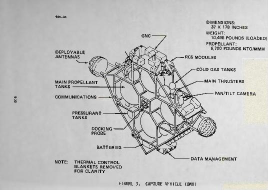
The Orbital Maneuvering Vehicle (OMV) is presently being defined for devel opment by NASA, with operational status planned for 1990. Figure 3 depicts a representative OMV config uration. The OMV is a remotely con trolled, free-flying vehicle capable of performing a wide range of on-orbit services including routine payload placement and retrieval, payload re- boost and deboost, and payload ser- ing. The initial OMV, equipped with an extendable docking mechanism with an RMS end effector, has the capa bility to do the rate matching and capture activities identified herein.
Propellant off-loading may be desira ble, depending on whether this demon stration is the only on-orbit activity planned for the OMV. One thousand pounds of propellant is sufficient for the defined activities, and will
provide a large margin for any contin gency situations. The OMV main pro pulsion system will be used for approach and fly-around activities, while the RCS alone will provide ma neuvering and rate matching for actual target vehicle capture. Figures 4 and 5 reflect OMV capabilities and impulse requirements to do circumnavigation of a target.
DOCKING/CAPTURE MECHANISMS
A docking mechanism concept for the proposed demonstration is shown in figure 6. The docking probe is par tially recessed whenever the OMV is in the cargo bay. After deployment of the OMV, the probe is extended to pro vide an end effector reach of approxi mately 48 inches. This length is re quired to preclude interference be tween the OMV and the SPAS sill trun- ion. Some potential advanced capture systems for unusual conditions are shown in figure 7.
OMV/SPAS PROXIMITY OPERATIONS
The OMV controlled flight will be done in three phases: (1) OMV approach and fly-around the SPAS; (2) OMV position and capture the SPAS with simple spin; and, (3) OMV position and capture SPAS with complex motion. During phases 1 and 2 the SPAS will be spinning at 2-5°/second around the Y-axis. For phase 3 activities, the same spin will be induced plus coning (wobble) as shown in figure 2. In all phases the SPAS attitude control system will be de-activated to avoid coupling of the two control systems. Fly-around of the target will be done in the Z-plane at 30 feet from the target. The operator at the ground control station will match rates and make observations prior to positioning the OMV for phase 2 cap ture. Two circumnavigations should be adequate, however, at this point some liberty should be given the operator, since the OMV must translate from the circumnavigation position to a position for capture at the aft end of the tar get.
After the initial capture has been effected and the SPAS stabilized (de- spun) , the OMV will release the SPAS and move to a position 100 feet away. At this time the SPAS control system will be re-activated and the appropriate ^commands given from the Orbiter to in duce the spin and coning as shown in figure 2. A 16° cone angle will cause the docking grapple fixture to describe
8-16

a circle of approximately 48 inches in diameter. This motion, coupled with a 2-5°/second spin, is considered adequate for the demonstration and is within the system and operator capability. After the SPAS has been brought under control, the total sys tem will be powered down in prepara tion for recovery by the Orbiter.
MISSION SEQUENCE
Figure 8 shows the relative position of the three vehicles involved in the demonstration. Generally, the Orbiter deploys the SPAS then moves away to a safe distance; then the Orbiter deploys the OMV and again moves away to a safe distance; finally the OMV approaches the SPAS and the Orbiter moves into position for observation. Figure 9 is a sim plified block diagram of the demon stration events. The entire flight demonstration, including OMV and SPAS deployment and checkout, can be done in three daylight periods, assuming ETR launch. Proximity operations will be curtailed during eclipse periods.
Since the on-orbit activities are pioneer in nature, some allowances should be made in the time block for unexpected occurrences such as mid- docks requiring second attempts, and for operator orientation. It must be recognized that the operator is doing real-time control of the OMV using hand controllers, and depending on video display and range/range rate data feedback for maneuver/docking information. Close proximity opera tions will be curtailed during eclipse periods.
COMMUNICATIONS
Communication links for on-orbit activities are shown pictorially in figure 10. Communications with the SPAS will be from the Orbiter only over the S-bank link. Communications with the OMV will be via the TDRSS Ground Station, K-band to the TORS, then S-band to the OMV. The link be tween the OMV Ground Control Station and the TDRSS Ground Station is not defined, but may be either over land lines, or via some relay satellite such as DOMSAT.
CONCLUSIONS
The flight demonstration discussed is considered feasible in terms of exist ing technology, projected hardware
availability, and programmatic consid erations. The pacing item is the OMV which, based on present planning will be available in 1990. This on-orbit activity presupposes operational status for the OMV, and assumes that it has already demonstrated capability to cap ture a stable satellite. Extensive simulation work involving high fidelity systems is essential to this and follow- on work in this challenging and reward ing area of work.
REFERENCES
1. Ball Brothers Research Corporation, Experiments for Satellite and Mate rial Recovery from Orbit, Final Re port to NASA Contract NAS8-18119, March 1967.
2. Arun A. Nadkarni, Teleoperator Con trol for Passivation of Satellites Possessing Angular Momentum, Pennsylvania State University, pub lished as Astronautics Research Report Number 75-2, April 1975.
3. G. C. Faile, D. N. Counter andE. J. Bourgeois, Dynamic Passiva tion of a Spinning and Tumbling Satellite Using Free-Flying Tele- operators, Internal Report, Marshall Space Flight Center, September 1972.
4. James M. Patterson, Investigation of Satellite Retrieval Concepts, Internal Report Number ASR-PD-SA- 71-3, Marshall Space Flight Center, September 1971.
8-17
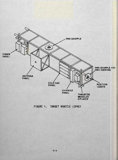
POWER PANEL
ANTENNA PANEL
RMS GRAPPLE
RMS GRAPPLE FOR OMV DOCKING
COLD GAS PANEL
AVIONICS PANEL
THRUSTER MODULES 4 PLACES
POSITION LIGHTS
FIGURE 1. TARGET VEHICLE (SPAS)
8-18

FLIGHT PATH
Y-AXIS
PHASE ONE SPIN RATE = 2-5°/sec
Z-AXIS
-X-AXIS
PHASE TWO
SPIN RATE = 2-5°/sec CONE ANGLE = 16°
NUTATION RATE = 1°/sec
DOCKING PROBE
FIGURE 2. TARGET VEHICLE MOTION
8-19
924-84
oo
DEPLOYABLE ANTENNAS
MAIN PROPELLANT TANKS ———————
COMMUNICATIONS
PRESSURANT TANKS
GNC
RCS MODULES
DIMENSIONS: 37 X 178 INCHES
WEIGHT:10,496 POUNDS (LOADED)
PROPELLANT:6,700 POUNDS NTO/MMH
COLD GAS TANKS
MAIN THRUSTERS
PAN/TILT CAMERA
NOTE:
DOCKING PROBE
BATTERIES
THERMAL CONTROL BLANKETS REMOVED FOR CLARITY
DATA MANAGEMENT
FIGURE 3. CAPTURE VEHICLE (OMV)

30 T
u u- 25-1C9
* 20H
3 J 15-
u 10-i
5-
15
OMV WITH FULL PROPELLANT LOAD
0 (CIRCUM NAVIGATION
^ ^ TO RATE MATCH WITH TARGET)
STANDOFF DISTANCE
30 45 60 75
CIRCUMNAVIGATION RATE (DEG/SEC) (ALSO TARGET SPIN RATE)
FIGURE 4, OhV CIRCUMNAVIGATION CAPABILITY
90
8-21

114-84
10000 iUJ_J uuz o 8000
6000
SN>
D O:= - 4000iocUJQ.
OMVWITH FULLPROPELLANTLOAD
UJ CO_lDa.
2000-
STANDOFFDISTANCE (CIRCUMNAVIGATION
TO RATE MATCH WITH TARGET)
10 15 20 25 30 35 40 45
CIRCUMNAVIGATION RATE (DEG/SEC)
FIGURE 5. IMPULSE REQUIRED TO CIRCUMNAVIGATE
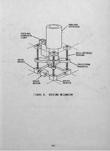
DOCKING CAMERA & LIGHT
GEAR BOXES
RMS END EFFECTOR
BALL BEARING SCREWS
CRUCIFORM PEDESTAL
DRIVE MOTOR
DRIVE SHAFTS
FIGURE 6. DOCKING MECHANISM
8-23

OMV WITH MITTENS
OPTIONAL END EFFECTOR
SPHERICAL TRAP
ADHESIVE END EFFECTOR
FIGURE 7. POTENTIAL FUTURE CAPTURE SYSTEMS
8-24

• ACTIVATED
POSITION FOR OBSERVATION DEPLOY OMV
FIGURE 8. RELATIVE POSITION OF VEHICLES
8-25

DEPLOY SPAS
ORBITER MOVE AWAY
• — *• DEPLOY OMV AND CHECKOUT
ORBITER MOVE AWAY
__ ̂
OMV FLY AROUND SPAS
9
OMV CLOSE AND MATCH RATES
POSITIONrtDDITCDUnDl 1 tn TO OBSERVE
10
OMV CAPTURE SPAS
OMV APPROACH SPAS
11
OMV DESPIN SPAS
INDUCE SIMPLE SPIN IN SPAS
12
OMVpci CA&PriC tCnOCSPAS
16 15 14
OMV OMV CLOSEUArlUKCSPAS
17
OMV TAKE OUT SPAS MOTION
ANU MA 1 t.nRATES
18
ORBITER CAPTURE OMV/SPAS
INDUCE SPIN PLUS CONE IN SPAS
13
OMVMOVEAWAY
FIGURE 9. MISSION SEQUENCE
8-26

TORS GRND STATION
OMVGRNDSTATION
FIGURE 10. COMMUNICATIONS
8-27