capital cooling dcs
TRANSCRIPT
8/4/2019 Capital Cooling DCS
http://slidepdf.com/reader/full/capital-cooling-dcs 1/24 introduction – energy and district cooling 1
1
energy and district cooling
Introduction
introduction

8/4/2019 Capital Cooling DCS
http://slidepdf.com/reader/full/capital-cooling-dcs 2/24 2 introduction – energy and district cooling
This education aterial has been written b Caital Cooling.
For urther inoration or questions, lease contact Anders Rubenhag at +46 (0) 70 617 77 24or e-ail [email protected]. All rights resered. Coright Caital Cooling.

8/4/2019 Capital Cooling DCS
http://slidepdf.com/reader/full/capital-cooling-dcs 3/24 introduction – energy and district cooling 3
1
course goal. Ater having participated in this course, participants shall have overall knowledge o energy use
rom a global perspective with a special ocus on buildings, the environmental impact o global energy use and
international agreements on how to reduce the environmental impact o energy production. Participants shall
also learn about what maintaining good indoor climate requires, the technical solutions employed to achieve this,
and how conventional comort cooling methods inuence the global and local environments. Finally, participants
will learn what district cooling is, its advantages in relation to methods currently employed by customers, and what is required or the successul establishment o district cooling on the market.
The goal 3
everyThing in The universe is made of energy 4
greaT need of cooling 9
disTricT cooling 17
The markeT 20
The hisTory of disTricT cooling 21
noTes 22
8/4/2019 Capital Cooling DCS
http://slidepdf.com/reader/full/capital-cooling-dcs 4/24 4 introduction – energy and district cooling
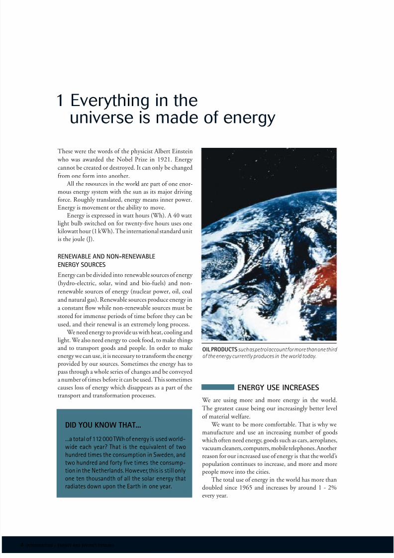
These were the words o the physicist Albert Einstein
who was awarded the Nobel Prize in 1921. Energy
cannot be created or destroyed. It can only be changed
rom one orm into another. All the resources in the world are part o one enor-
mous energy system with the sun as its major drivingorce. Roughly translated, energy means inner power.Energy is movement or the ability to move.
Energy is expressed in watt hours (Wh). A 40 wattlight bulb switched on or twenty-fve hours uses onekilowatt hour (1 kWh). The international standard unitis the joule (J).
renewable and non-renewable
energy sources
Energy can be divided into renewable sources o energy
(hydro-electric, solar, wind and bio-uels) and non-
renewable sources o energy (nuclear power, oil, coaland natural gas). Renewable sources produce energy in
a constant ow while non-renewable sources must be
stored or immense periods o time beore they can be
used, and their renewal is an extremely long process. We need energy to provide us with heat, cooling and
light. We also need energy to cook ood, to make thingsand to transport goods and people. In order to makeenergy we can use, it is necessary to transorm the energy provided by our sources. Sometimes the energy has topass through a whole series o changes and be conveyeda number o times beore it can be used. This sometimes
causes loss o energy which disappears as a part o thetransport and transormation processes.
1 Everything in theuniverse is made of energy
energy use increases We are using more and more energy in the world.
The greatest cause being our increasingly better level
o material welare. We want to be more comortable. That is why we
manuacture and use an increasing number o goods which oten need energy, goods such as cars, aeroplanes,vacuum cleaners, computers, mobile telephones. Anotherreason or our increased use o energy is that the world’spopulation continues to increase, and more and morepeople move into the cities.
The total use o energy in the world has more than
doubled since 1965 and increases by around 1 - 2%every year.
did you know that...
...a total o 112 000 TWh o energ is used world-wide each year? That is the equivalent o two
hundred ties the consution in Sweden, andtwo hundred and ort fe ties the consu-tion in the Netherlands. Howeer, this is still only
one ten thousandth o all the solar energ that
radiates down uon the Earth in one ear.
oil productssuch as petrol account or more than one third o the energy currently produces in the world today.

8/4/2019 Capital Cooling DCS
http://slidepdf.com/reader/full/capital-cooling-dcs 5/24 introduction – energy and district cooling 5
major differences among counTries
USA, China and Russia use the most energy. USA
and Canada together account or almost one third o
total world energy use in spite o the act that only
one twentieth o the population o the Earth live in
North America.Utilisation o energy diers greatly among countries.
On average, a person in Arica uses 4.4 MWh per year.In Europe the average is 41 MWh, with Swedes using73 MWh and the Netherlanders around 49 MWh.
oil dominaTes
Most energy used in the world comes rom oil. Oil
and its' derivatives, such as petrol and diesel, account
or more than one third o the energy used in all the
countries o the world. Fossil uels – oil, coal and natural
gas – provide around 80% o all uels used (oil 37%,coal 23%, natural gas 20%). Bio-uels, such as wood,
provide approximately 11%. Electricity produced by
nuclear and hydroelectric power plants account or 7,
respectively 2%. Wind power is under expansion in many places in
the world, however so ar it accounts or less than 0.1%o the world’s energy needs.
what affects
the environment?
modern energy use
damages The environmenT
Nearly all the ways we produce and manuacture energy cause damage to the environment. Combustion o oil
and other ossil uels contribute to most environmental
problems. The most serious being the development o
the greenhouse eect which is changing the climate
o the Earth.
naTural greenhouse effecT is beneficial
The natural greenhouse eect is, in act, the prerequisite
o all lie on Earth. Carbon dioxide and other gases in
the Earth’s atmosphere capture and retain heat rom
the sun. Just like the panes o glass in a greenhouse do. Without this natural greenhouse eect it would be al-
most 35 degrees colder on Earth than it is today.The problem is that the activities o human beings
tend to magniy this natural greenhouse eect, the pri-mary culprit being their habit o burning ossil uels.
All ossil uels emit carbon dioxide which is the mostrapidly increasing greenhouse gas.
energy facts from some eu countries
On Iceland, two thirds o all housing is heated b geotheric heating sstes, i.e. heat ro deein the Earth’s crust (which also gie the their hot srings).
Lueburg is the sallest countr in the EU, but it shows the highest leel o energ use er erson.To a great etent this is due to the act that uel rices in Lueburg are low, so an goods trans-orts through Euroe choose to refll their diesel tans in Lueburg.
EU’s our largest countries, Geran, France, Ital and Great Britain, use aroiatel 70% o total EU energ.
The fteen eber states o the EU use around 15% o the energ used in the world.

8/4/2019 Capital Cooling DCS
http://slidepdf.com/reader/full/capital-cooling-dcs 6/24 6 introduction – energy and district cooling
carbon dioxide emissions
change The earTh’s climaTe
Currently the level o carbon dioxide in the atmosphere
is 30% higher than it was 150 years ago. Researchers at
IPCC, the UN organisation, believe that this increase
has already started to change our climate. For example
the Earth’s average temperature has increased by hal
a degree during the last hundred years, glaciers havemelted and sea level has risen by ten centimetres.No one knows or sure what will happen in the u-
ture. But researchers predict that the average temperature will rise by 1.5 - 5.5 degrees by 2100, which will meanserious climate changes all over the world.
People who live in the third world suer most. In thecountries around the equator where it already is hot anddry, the risk o drought, harvest ailure, starvation andmass movement o population is increasing. Sea level isexpected to rise by 40 centimetres, which could meansevere ooding o islands and coastal areas. Plants andanimals will disappear as climate zones shit.
acidificaTion, excessive
ferTilizaTion and dangerous emissions
Combustion o ossil uels also causes or contributes to
a number o other environmental problems. Emissions
o sulphur dioxide and nitrogen oxides have upset the
pH balance o thousands o Nordic lakes. Nitrogen
emissions rom trafc and energy plants have also con-
tributed to acidifcation o water and soil. In the cities,ossil uel emissions cause people to become ill, and old
buildings and statues to crumble away.
eu
eu inTends To decrease The effecTs
of energy on The environmenT
The energy use picture diers between the countries
o the EU. Countries determine their own energy and
transport policies to a great extent, however there are
joint EU objectives in some areas.
sweden and The neTherlands
rely on differenT resourses
EU countries have many dierent climates and popula-
tion sizes; another major dissimilarity is access to natural
resources. For example Sweden is one o the largest users
o bio-uel (wood) in Europe and hydroelectric power
produces almost hal its electricity. The Netherlands
has neither orests nor mountain rivers but it does have
major natural gas resources, consequently around hal
its energy needs are supplied by natural gas.
joinT efforTs for a beTTer environmenT...
By mobilising joint eorts, EU countries intend to
decrease the environmental eects o energy use and
transport. Some examples o these eorts:Use o renewable sources o energy – solar, wind and
bio-uels – must increase rom 6% o total energy use in2000 to 12% in 2010. Currently oil is the dominatingsource o energy in the EU.
Environmental impact o transport must decrease.
Methods include shiting goods transport rom trucksto railways and sea reight. EU has also agreed with
the netherlands hasneither extensive orests not moun-
tain rivers, but it does have signifcant natural gas resources which supply approximately hal o its energy needs.
8/4/2019 Capital Cooling DCS
http://slidepdf.com/reader/full/capital-cooling-dcs 7/24 introduction – energy and district cooling 7
automotive manuacturers in Europe, South Korea and Japan that their products’ carbon dioxide emissions areto decrease by one quarter between 1995 and 2008.Currently transport accounts or one third o EU’s totalenergy utilisation and the amount o transport withinthe EU increases by 2 - 3% every year.
...and a common markeT for energy
Since the end o the 1990's, the EU has been develop-
ing a common market or energy. This will be achieved
by connecting the electricity grids o all the countries
into one, border-to-border network covering all o Eu-
rope. The Nordic countries already use a common grid
(Nordel) but many other EU countries still operate their
own. A common grid would mean electricity could be
exported and imported; companies and households
would be able to select their own supplier. The EU
hopes that this will increase competition and decrease
energy prices or companies and consumers.
Similar activities are underway concerning a commonnatural gas pipe network or all EU countries.
what is being done?
The mosT difficulT Task
is To sTop climaTe change
Through international conventions and agreements,
the countries o the world have managed to decrease a
number o dangerous emissions caused by use o energy.
However, the most difcult task remains – putting astop to the greenhouse eect which is changing the
climate o the Earth.The only way to decrease carbon dioxide emissions
and human beings’ aect on the climate is to use less oil,coal and natural gas. Whenever ossil uels are burned,
carbon dioxide is always emitted. It cannot be removedby any puriying processes. We must decrease our totalenergy utilisation instead and move to wind power, bio-uels and other renewable sources which do not have anegative eect on the environment.
This has, however, proved to be easier said than done.In the rich countries we have become used to travellingby car, use as much electricity, air-conditioning and
heating we eel we need, and we do not want to changeour habits. In addition, so ar renewable types o energy have been much more expensive.
indusTrial counTries bear
The main responsibiliTy
Through their activities with the UN Climate Conven-
tion, many countries have promised to decrease their
emissions o greenhouse gases. It is the responsibility
o the richer, industrialised countries to ensure that
this is done. In the Kyoto Protocol, which is a part o
the Climate Convention, industrialised countries haveundertaken to decrease their emission o greenhouse
gases. EU countries must reduce emissions overall to
8% o the 1990 level by 2012. An internal division o responsibility has been agreed
within EU in which emissions per capita have been takeninto consideration. Consequently, the countries with themost emissions have to make the biggest decreases.
emissions of oTher polluTanTs
have decreased
Emissions o sulphur, nitrogen oxides and other pollu-tion have, in certain cases, already decreased thanks to
international agreements. Through the UN Nitrogen
Protocol several countries have promised to decrease
nitrogen emissions by 30 - 80% between 1980 and
2010.
did you know that...
...the USA is resonsible or 45 ercent o OECD countries carbon dioide eissions? Other ajoremission countries include Japan, Germany and Great Britain. On average, every American emits
21 tons o carbon dioide eer ear.

8/4/2019 Capital Cooling DCS
http://slidepdf.com/reader/full/capital-cooling-dcs 8/24 8 introduction – energy and district cooling
Emissions o nitrogen oxides have decreased thanks
to various purifcation measures, however not to the
same degree as or sulphur emissions. EU member
states have agreed upon an emissions ceiling or ni-
trogen oxide. The act that we nowadays use catalytic
converters to puriy exhaust rom our vehicles has
decreased nitrogen emissions considerably.
environmental impact
of a building
The EU Commission has calculated that the share
o greenhouse gas emissions in the EU produced by
buildings amounts to 41% – more than trafc (31%)
and industry (28%)! A major part o the environ-
mental impact o a building is generated by its use
– heating, cooling, lighting, hot tap water etc.On 16 December 2002, the Council o Ministers
adopted a directive on the application o minimum
energy requirements or new buildings. This direc-tive has been in orce since the beginning o 2003.The directive stipulates that the design and planningo all new buildings with a useul oor space o over1 000 m2 must consider the easibility o systemsbased on renewable energy sources, CHP, district orblock heating/cooling (i available) and heat pumpsbeore actual construction begins.
example of energy use in an office
LIGHTINGCOOLING
HEAT
COpyING
FAx
COmpUTERS
ELECTRICALAppLIANCES
HOT WATER
vENTILATION
nordic office building
energy forms and Theiraverage consumpTion per year
Heat – 80 kWh/m2
Comort cooling – 42 kWh/m2
Process cooling – 15 kWh/m2
Electrical Power – 57 kWh/m2
Water consumption – 300 liter/m2
Greenhouse eect – 15 kg CO2
ekv/m2
LIGHTINGCOOLING
HEAT
COpyING
FAx
COmpUTERS
ELECTRICALAppLIANCES
HOT WATER
vENTILATION
figure 1. An office building is dependent upon energy tobe able to function. Computers, copying machines and light-ing consume large amounts of energy while emitting large amounts o heat.
69 67 23 14
16 7 33 41
99 119 72 51
13 13 17 24
office kWh/m2, year
o s l o
( n o r
w a y )
h e l s i n k
i
( f i n l
a n d )
o b e r h a
u s e n
( g e r m a
n y )
s e u o
l
( k o r e a )
residential kWh/m2, year
Specifc heating demand
Specifc cooling demand
Specifc heating demand
Specifc cooling demand
heating/cooling demands

8/4/2019 Capital Cooling DCS
http://slidepdf.com/reader/full/capital-cooling-dcs 9/24 introduction – energy and district cooling 9
buildings
Building tenants have progressively increased their
requirements concerning what eatures a commercial
premises should oer. These include:
Attractive building interior and exterior
Flexible working areas
IT and communication
Interior work environment
Eective environmental and energy solutions
Trafc, transport, parking and services
whaT is an inTerior environmenT?
How people perceive an interior environment is de-
pendent upon a variety o actors. As seen in the fgure,
many important actors are based upon technology,
e.g. sounds/noise, light, and the electrical environment.
Aside rom these physical actors, psychological andsocial actors also play an important role.It may also be important to the occupants o a
building to eel that they can aect conditions in theindoor environment by doing such things as openinga window.
In a work place, relationships with other people andthe nature o the work also have an eect upon how theenvironment is perceived.
comforT cooling
Having a comortable work place climate is an impor-
tant element in the creation o a suitable indoor en-vironment. For this reason, having comort cooling is
equally as important as having a good heating system.
At present, about 10% o the world’s production o
electricity is used to create process and comort cooling.
In the USA and Japan, about 80% o all commercial
and institutional buildings now make use o it. In Eu-
rope however, the fgure is only around 40 - 50%, but
is increasing rapidly. To urther illustrate this trend,
presently 90% o all cars now have air-conditioning,
while in 1990, it was only 10%.In ofces and some industrial buildings, internal heat
generation is signifcant. People, printers, computers,and other machines are all examples o locally generated
2 Great need of cooling
?
sources o heat. Since building technology has experi-enced great advances, resulting in increasingly bettermaterials, the loss o heat through the roo, walls andoor in oten slight.
Newer buildings, such as ofce buildings, warehousesand hospitals almost always have a signifcant excess o heat during the day, while being “defcient” in heat duringnights and weekends. A simple heating system can handlethe modest lack o heat during the nights and weekends,however a much larger system is needed to deal with thepotentially tremendous amounts o daytime excess heat
to keep the indoor temperatures rom varying too muchand making the environment comortable.
figure 2. How people perceive an interior environment is dependent upon a variety o actors. As seen in the fgure, many important actors are based upon technology, e.g. sounds/noise, light, and the electrical environment. Aside from these physical factors, psychological and social actors also play an important role.
interior environment
Thermal
climaTe
facTors linked ToThe individual
physiological
facTors
physicalenvironmenT
psychological
facTors
social
facTors
geneTic facTorselecTrical
environmenT
lighT
sound/noise
air qualiTy
8/4/2019 Capital Cooling DCS
http://slidepdf.com/reader/full/capital-cooling-dcs 10/24 10 introduction – energy and district cooling
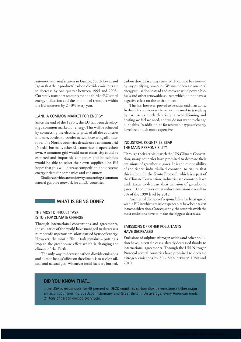
Two systems are needed to be able to remove the ex-cess heat, i.e. to meet the building’s cooling needs, andmaintain a comortable indoor temperature.
A cooling system that produces cooling
A climate control system that can remove excessheat rom all areas o the building
There are given requirements or the room temperaturein a work environment. The cooling system’s size is de-termined mainly by how much excessive heat must beremoved. The greater the amount o excess heat, themore capacity the cooling system must have, and themore difcult it is to maintain a room temperature thatis comortable.
cooling systems
and their main components
The usual procedure or generating cooling energy isby means o local, electric motor driven rerigeration
machines. Systems that exceed a rating o 1 000 kW
normally eature heat recovery rom the condensing cir-
cuit in order to improve the local energy efciency.
+
++
-
+
figure 3. Example of traditional cooling system. A roof-mounted rerigeration machine unit cools the outdoor air ei-ther by means o a direct evaporation coil in the air handlingsystem that delivers the cooled air, or by means o a rerigerationmachine unit that produces chilled water, generally known as brine. The brine is conveyed by a secondary pipe system to acooling coil in the air handling system o the building, whichthus cools the premises.
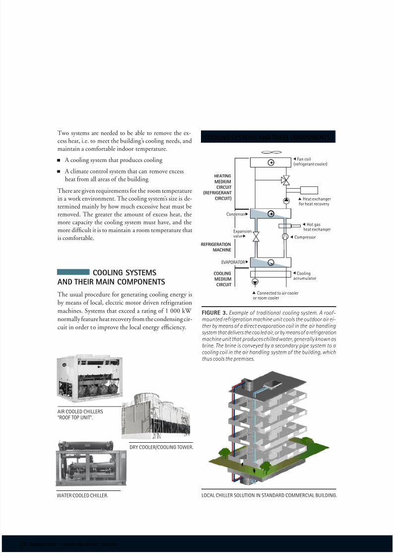
cooling systems and their components
Fan coil(rerigerant cooler)
heating
medium
circuit
(refrigerant
circuit) Heat echangeror heat recoer
Hot gasheat echanger
refrigeration
machine
Coressor
Coolingaccuulator
cooling
medium
circuit
AIR COOLED CHILLERS”ROOF TOp UNIT”.
WATER COOLED CHILLER. LOCAL CHILLER SOLUTION IN STANDARD COmmERCIAL BUILDING.
DRy COOLER/COOLING TOWER.
Condenser
EvApORATOR
Eansionale
Connected to air cooleror roo cooler

8/4/2019 Capital Cooling DCS
http://slidepdf.com/reader/full/capital-cooling-dcs 11/24 introduction – energy and district cooling 11
The cooling energy delivered by a rerigeration machinesystem in relation to the electrical energy consumed– which is known as the coefcient o perormance orCOP or short – normally ranges rom 2 to 3. Alterna-tive methods are available today to the conventionalrerigeration machine systems, such as evaporative andsorption cooling systems. In large plants with a cool-ing energy demand o more than 1 000 kW, cooling
energy produced by heat-driven absorption machinesis also available.
Evaporative and sorption systems dier on oneundamentally important score rom other systems by being usable only in systems with airborne cooling en-ergy. Cooling energy generated by means o absorptionmachines is suitable only or very large systems.
whaT is evaporaTive cooling?
In evaporative cooling, the air temperature is reduced
by the air being humidifed by the evaporation o water
rom a wet surace over which the air ows. Humidi-
fcation is possible as long as the air is not saturated
with water vapour. Heat is needed to evaporate water.
This heat, known as the latent heat o evaporation,
is supplied by the air. As the water is evaporated and
absorbed by the air, the air temperature will drop. The
lowest temperature attainable by this type o cooling
is limited by the wet bulb temperature o the air in its
saturated condition, which is also known as the cool-
ing limit o the air.Evaporative cooling can be classifed into direct and
indirect cooling:Direct evaporative cooling is a process in which
the supply air in a ventilation system is humidifedand its temperature is reduced, while the moisturecontent o the supply air simultaneously increases(see Figure 4).
In indirect evaporative cooling, the exhaust air in theventilation system is humidifed and its temperature isthereby reduced. Heat exchange (without moisture trans-er) then takes place between the exhaust air and supply air, in which the heat rom the supply air is transerredto the exhaust air. This lowers the supply air temperature
without its moisture content increasing.In the sorption cooling process, humidifcation rom
the evaporative process is supplemented by drying o thesupply air beore it is humidifed.
climaTe conTrol sysTem of a building
The unction o the climate control system in a building
is to maintain both the thermal climate (air humidity
and temperature) and the air quality.Maintaining the thermal climate involves mainly
maintaining the room air temperature within specifedlimits, and also meeting any requirements on comortcooling.
Maintaining the air quality consists o controllingthe room air cleanliness by ensuring that outdoor air ata sufcient ow rate ventilates the room. It sometimes
also involves ensuring that the specifed limits o particlesand/or gases are not exceeded.
figure 4. In evaporative cooling, the air temperature is reduced by the air being humidifed by the evaporation o water rom awet surace over which the air fows. Humidication is possible as long as the air is not saturated with water vapour.
SUppLy AIR IS HUmIDIFIEDAND THE TEmpERATURE SINkS
direct evaporative cooling
8/4/2019 Capital Cooling DCS
http://slidepdf.com/reader/full/capital-cooling-dcs 12/24 12 introduction – energy and district cooling
The climate control systems used or cooling buildingscan generally be classifed into three types:
Airborne cooling systems
Waterborne cooling systems
Combined systems (the air and water both supply cooling energy)
airborne cooling sysTems
The cooling system must be able to accommodate vari-
ations in cooling demand, both over a 24-hour period
and over the year. The two undamental types o airborne
cooling systems are constant air ow systems, known
as constant air volume or CAV systems, and variable
air ow systems, known as variable air volume or VAV
systems (although combinations o the two methods
are sometimes also employed).In these systems, the rate o air ow and thus also the
duct sizes are determined by the cooling requirements.
The sizing is thus determined by the thermal require-ments, and not by the air quality requirements.
The undamental arrangement o an airborne coolingsystem is shown schematically in Figure 5. In existingsystems, it is usually both difcult and costly to changethe duct system. I the existing ducts are not capable o conveying sufciently large air ows in order to meetthe cooling requirements, the system is usually upgraded
by installing water-borne cooling systems.
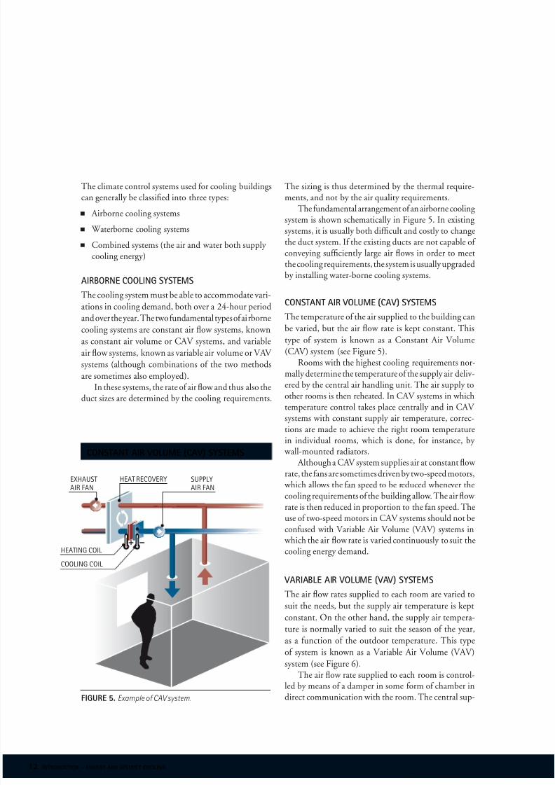
consTanT air volume (cav) sysTems
The temperature o the air supplied to the building can
be varied, but the air ow rate is kept constant. This
type o system is known as a Constant Air Volume
(CAV) system (see Figure 5).Rooms with the highest cooling requirements nor-
mally determine the temperature o the supply air deliv-ered by the central air handling unit. The air supply toother rooms is then reheated. In CAV systems in whichtemperature control takes place centrally and in CAV systems with constant supply air temperature, correc-tions are made to achieve the right room temperaturein individual rooms, which is done, or instance, by
wall-mounted radiators. Although a CAV system supplies air at constant ow
rate, the ans are sometimes driven by two-speed motors, which allows the an speed to be reduced whenever thecooling requirements o the building allow. The air ow rate is then reduced in proportion to the an speed. Theuse o two-speed motors in CAV systems should not beconused with Variable Air Volume (VAV) systems in
which the air ow rate is varied continuously to suit the
cooling energy demand.
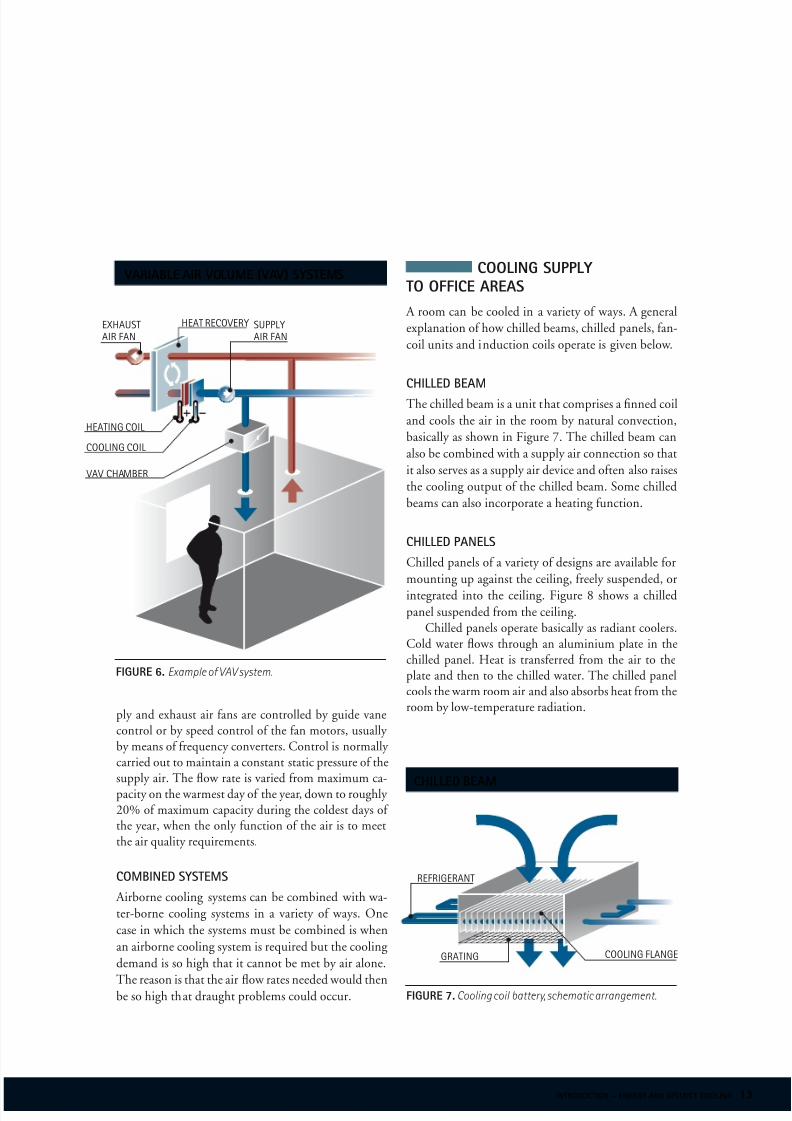
variable air volume (vav) sysTems
The air ow rates supplied to each room are varied to
suit the needs, but the supply air temperature is kept
constant. On the other hand, the supply air tempera-
ture is normally varied to suit the season o the year,
as a unction o the outdoor temperature. This type
o system is known as a Variable Air Volume (VAV)
system (see Figure 6).The air ow rate supplied to each room is control-
led by means o a damper in some orm o chamber indirect communication with the room. The central sup-
constant air volume (cav) systems
ExHAUSTAIR FAN
HEAT RECOvERy
HEATING COIL
COOLING COIL
SUppLyAIR FAN
figure 5. Example o CAV system.
8/4/2019 Capital Cooling DCS
http://slidepdf.com/reader/full/capital-cooling-dcs 13/24 introduction – energy and district cooling 13
ply and exhaust air ans are controlled by guide vanecontrol or by speed control o the an motors, usually by means o requency converters. Control is normally carried out to maintain a constant static pressure o thesupply air. The ow rate is varied rom maximum ca-pacity on the warmest day o the year, down to roughly 20% o maximum capacity during the coldest days o the year, when the only unction o the air is to meetthe air quality requirements.
combined sysTems
Airborne cooling systems can be combined with wa-
ter-borne cooling systems in a variety o ways. One
case in which the systems must be combined is when
an airborne cooling system is required but the cooling
demand is so high that it cannot be met by air alone.
The reason is that the air ow rates needed would thenbe so high that draught problems could occur.
variable air volume (vav) systems cooling supply
to office areas
A room can be cooled in a variety o ways. A general
explanation o how chilled beams, chilled panels, an-
coil units and induction coils operate is given below.
chilled beam
The chilled beam is a unit that comprises a fnned coil
and cools the air in the room by natural convection,
basically as shown in Figure 7. The chilled beam can
also be combined with a supply air connection so that
it also serves as a supply air device and oten also raises
the cooling output o the chilled beam. Some chilled
beams can also incorporate a heating unction.
chilled panels
Chilled panels o a variety o designs are available or
mounting up against the ceiling, reely suspended, or
integrated into the ceiling. Figure 8 shows a chilled
panel suspended rom the ceiling.Chilled panels operate basically as radiant coolers.
Cold water ows through an aluminium plate in thechilled panel. Heat is transerred rom the air to theplate and then to the chilled water. The chilled panelcools the warm room air and also absorbs heat rom theroom by low-temperature radiation.
chilled beam
vAv CHAmBER
ExHAUSTAIR FAN
HEAT RECOvERy SUppLyAIR FAN
HEATING COIL
COOLING COIL
GRATING
figure 7. Cooling coil battery, schematic arrangement.
REFRIGERANT
figure 6. Example o VAV system.
COOLING FLANGE

8/4/2019 Capital Cooling DCS
http://slidepdf.com/reader/full/capital-cooling-dcs 14/24 14 introduction – energy and district cooling
chilled panel
fan coil uniT A an-coil unit is usually located under a window along
an outer wall. A an-coil unit can be used or supplying both heat
and cooling energy to the room (although not at thesame time). A schematic arrangement o a an-coil unit isshown in Figure 9. A an-coil unit is equipped with a anthat circulates the room air through the unit. The air isheated or cooled in the unit by a heating or cooling coil.The heating or cooling coil is supplied with hot or cold
water rom a central system in the building. The an-coilunit is a room cooler that can meet the highest cooling
demands, although its sound level is also highest.
inducTion uniT
An induction unit is usually located under a window
along an outer wall.The induction unit can supply the room with heat
or cooling energy. A schematic arrangement o an induc-tion unit is shown in Figure 10. When the inductionunit is in use, the room is supplied with ventilation airthrough the induction coil. The ventilation air ows athigh velocity through a nozzle, which entrains the roomair through the heating or cooling coil. This enables the
room to be heated or cooled by the same unit, withoutthe use o a an.
fan coil unit
induction unit
figure 8. Chilled panel, schematic arrangement.
ALUmINIUm pLATES FAN
figure 9. Fan coil unit, schematic arrangement.
WARm WATER
COLD WATER
SUppLy AIRExHAUST AIR
vENTILATION AIR IN
figure 10. Induction unit or outer wall placement,schematic arrangement.
WARm WATER
COLD WATER
ROOm AIR IN
ROOm AIR OUT
8/4/2019 Capital Cooling DCS
http://slidepdf.com/reader/full/capital-cooling-dcs 15/24 introduction – energy and district cooling 15
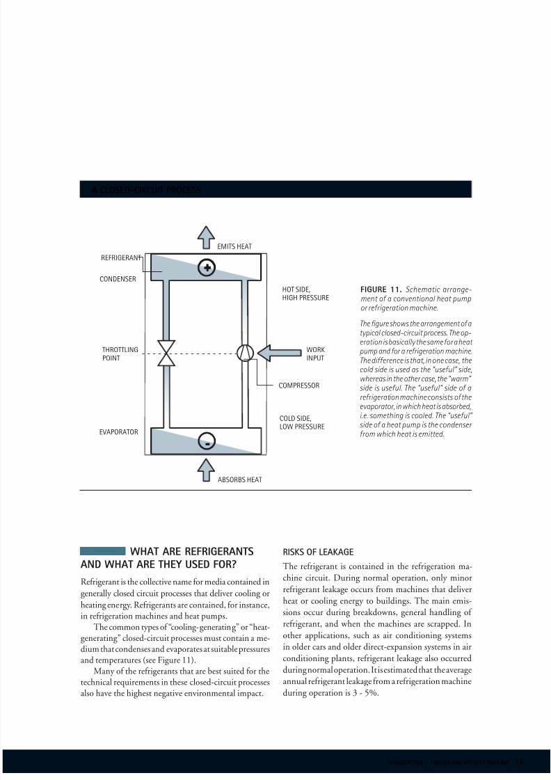
what are refrigerantsand what are they used for?
Rerigerant is the collective name or media contained in
generally closed circuit processes that deliver cooling or
heating energy. Rerigerants are contained, or instance,in rerigeration machines and heat pumps.
The common types o “cooling-generating” or “heat-generating” closed-circuit processes must contain a me-dium that condenses and evaporates at suitable pressuresand temperatures (see Figure 11).
Many o the rerigerants that are best suited or the
technical requirements in these closed-circuit processesalso have the highest negative environmental impact.
+
-
+
a closed-circuit process
risks of leakage
The rerigerant is contained in the rerigeration ma-
chine circuit. During normal operation, only minor
rerigerant leakage occurs rom machines that deliver
heat or cooling energy to buildings. The main emis-
sions occur during breakdowns, general handling o
rerigerant, and when the machines are scrapped. In
other applications, such as air conditioning systems
in older cars and older direct-expansion systems in air
conditioning plants, rerigerant leakage also occurred
during normal operation. It is estimated that the average
annual rerigerant leakage rom a rerigeration machineduring operation is 3 - 5%.
figure 11. Schematic arrange-ment of a conventional heat pumpor rerigeration machine.
EmITS HEAT
REFRIGERANT
CONDENSER
HOT SIDE,HIGH pRESSURE
THROTTLINGpOINT
WORkINpUT
COmpRESSOR
EvApORATOR
COLD SIDE,LOW pRESSURE
ABSORBS HEAT
The gure shows the arrangement o atypical closed-circuit process. The op-eration is basically the same or a heat pump and or a rerigeration machine.The dierence is that, in one case, the cold side is used as the “useul” side,whereas in the other case, the “warm” side is useful. The “useful” side of arerigeration machine consists o the
evaporator, in which heat is absorbed,i.e. something is cooled. The “useul” side o a heat pump is the condenser rom which heat is emitted.

8/4/2019 Capital Cooling DCS
http://slidepdf.com/reader/full/capital-cooling-dcs 16/24 16 introduction – energy and district cooling
climaTic impacT
The two concepts normally used in discussions con-
cerning the climatic impact o various rerigerants are
Ozone Depletion Potential (ODP) and Global Warming
Potential (GWP). ODP describes the impact in relation
to the impact o rerigerant R11. GWP describes the
impact in relation to carbon dioxide (CO2).
Rerigerants with ODP eect contain chlorine orbromine, and hydro uorocarbon (HFC) rerigerantsthereore have no ODP impact. On the other hand,they do have GWP impact.
The additional concept o Total Environmental Warm-ing Impact (TEWI) is beginning to come into use in orderto take into account also the indirect eect caused by thegeneration o the driving electricity. Using TEWI, com-parison is made o the eect over a certain period o time.However, it must be borne in mind that carbon dioxideand hydrocarbon compounds disappear rom the atmos-phere as a result o totally dierent mechanisms. NeitherGWP nor TEWI is thereby comprehensive.
The table shows a compilation o a number o re-rigerants and their environmental impact (accordingto the ODP and GWP concepts).
The use of refrigeranTs shall be phased ouT
Many rerigerants have a negative eect on the environ-
ment, and in accordance with EU environmental regu-
lations, the most aggressive rerigerants shall be phased
out in accordance with the ollowing timetable.
figure 13.A selection o rerigerants and their environmental
eects described with ODP and GWP. CFC, HCFC and haloner are marked in blue.
a selection of refrigerants
and their environmental effects
refrigerant category odp gwp
R11 CFC 1 4000
R12 CFC 1 8500
R12B1 HALON 3 *
R13 CFC 1 11700
R13B1 HALON 10 5600
R22 HCFC 0.055 1700
R23 HFC 0 11700
R32 HFC 0 650
R114 CFC 1 9300
R123 HCFC 0.02 93
R124 HCFC 0.022 480
R125 HFC 0 2800
R134a HFC 0 1300
R141b HCFC 0.11 630
R142b HCFC 0.065 2000
R143a HFC 0 3800
R152a HFC 0 140
R290 - 0 3
R404A HFC 0 3260
R407A HFC 0 1770R407C HFC 0 1600
R410A HFC 0 1900
R417A HFC 0 1940
R500 CFC 0.74 6310
R502 CFC 0.33 5590
R507 HFC 0 3800
0% 0% 0%0% 0%
35%
65%
90%99.5% 100% 100%
1996* 2004** 2004 2010 2015 2020 2030 2016* 2016** 2040
* CONSUmpTION CONTROL * * pRODUCTION CONTROL
refrigerant reductions
Reductions in industrialised countries (%)Reductions in thirdworld countries (%)
figure 12.

8/4/2019 Capital Cooling DCS
http://slidepdf.com/reader/full/capital-cooling-dcs 17/24 introduction – energy and district cooling 17
the production
of district cooling
Capital Cooling’s district cooling production methods
can take many orms, but the goal is to always fnd a
method that is ecologically sustainable. This means or
example, using methods such as ree cooling, i.e. using
chilled water rom lake or ocean bottoms. When these
methods are not possible, chilled water can also beproduced by using heat pumps, or waste heat.
There are a number o methods or producing chilled water or use in district cooling. They include:
Rerigeration machines and heat pumps
“Waste” chilled water
Absorption methods via waste heat, district heatingor natural gas
Deep water sources such as lakes, rivers and oceans
Groundwater
Snow and ice
Liquid Nature Gas
examples of
production methods
chillers
Capital Cooling does not normally use air/water cooled
chillers because they are relatively expensive to buy and
require a great amount o electrical energy. Using natural
sources (ree cooling sources) o cooling as a cooling
medium reduces energy costs as they are less expensivethan using air/water cooled units. During those times
in which the capacity or temperature o the ree cooling
sources is not sufcient to meet cooling needs, air/water
cooled chillers can o course be used. All project equipment is o the highest quality and
provides a high degree o eectivity and saety in com-
3 District Cooling
parison to the comort cooling units that are presently used by customers.
heaT exchanger
When lake or ocean water is introduced into a heat
exchanger, its low temperature cools down the return-
ing district cooling water. During the winter months all
cooling is produced using this method, while during thesummer months it usually ranges rom between 20%
to 50%. Plate exchangers are always used which are
o higher quality than other types o heat exchangers.
The equipment that cleans the heat exchangers ulflls
a very important unction and must be designed in ac-
cordance with prevailing local conditions to guarantee
high operational reliability.
free cooling sources
The water in Capital Cooling’s system is transported to
the production plant in a PE pipe. Ater arriving at theproduction plant the water is used to cool the chiller’s
condenser, or the district cooling water itsel.
Thermal sTorage
Thermal storage is one o many methods that Capital Cool-
ing has used to store excess chilled water or uture use, thus
resolving capacity problems. Chilled water can be stored
thermally during the winter, so that it can later be used
during the summer months, or stored or shorter periods
o time such as a twenty-our hours or thirty days. A variety o thermal storage methods may be chosen
rom when planning the installation o cooling acili-ties, so that optimal operational conditions are achieved.Three are listed below.
Aquier storage
Accumulator tanks
Ice storage
capital cooling’s definition of district cooling:
“District Cooling is considered to be all ors o cooling in which the cooling roduction is centralised,and the roduct is oered to a broader aret.”

8/4/2019 Capital Cooling DCS
http://slidepdf.com/reader/full/capital-cooling-dcs 18/24 18 introduction – energy and district cooling
the principle of district cooling
sea
distribution
underground pipes
Preabricated pipes are normally used or the under-
ground transport o the chilled water, precisely the same
as district heating, even though the investments costs
are higher than other alternatives. This system has been
chosen because it is the only system that can detect leak-
age. The demands and reliability o the underground
systems that transport chilled water are equally as high
as they are or systems carrying heating water, and a
high level o quality is necessary. Capital Cooling tracks
developments closely and chooses design and construc-
tion methods that best suit local conditions.
indoor piping
Pipes that are placed inside o a building are normally
made o stainless steel, and have polyurethane insulation
and an aluminium shell. Stainless steel is used insteado iron pipe because:
Standard piping can be used
They have a lower weight, easing transportand installation.
pipe alarm
The district cooling system is equipped with an alarm
that detects leaks and monitors or any possible mois-
ture or cable damage.The alarm signal can be sent to the production
plant via a cable or wirelessly, and then directed urtheras necessary.
shuT-off valves
When possible, the standard valve normally used is
the ball valve. Underground valves are pre-insulated
and equipped with an alarm cable. Larger versions o
these valves, and valves that are placed in areas making
i difcult to reach, e.g. under streets and roads, are
normally remote controlled.
waTer qualiTy
The choice o water or use in a district cooling system is
based upon an intelligent balancing o dierent elements.
Characteristics o good district chilled water are:
Free o oxygen
Low hydrogen ion concentration
Sludge and particle ree
No or low amount o ions contributing to hard water
Optimal water ow speed
substation’s construction
The substation contains a heat exchanger which creates
an interace between the supplier’s primary distribu-
tion network, and the customer’s internal distribution
system that cools the building.Substations with a capacity o under 2 MW can be
designed as preabricated units containing all necessary equipment to manage a substation’s unctions.
Those substations which have a capacity o more than2 MW are built on-site with all necessary equipment tomanage a substation’s unctions.
Figure 16 displays a system drawing o a substation’sdesign.
1. cold water. Water at a temperature o about 3 - 4° is
taken rom a sea or lake at a depth o between 20 - 50 metres.
2. cooling station. In the energy produc-tion centre the “cold” in the sea or lake water istranserred to the District Cooling Grid.
3. district cooling grid. The District Cooling Grid is a closed system with
pipes that are buried in the ground in which water is led to and rom buildings.
4. air cools. The air that circulates in the ventilation system is cooled by theapproximately 6° Celsius water being pumped through the District Cooling Grid.
5. the warmed water. The warmed water whichis about 16° Celsius is returned to the sea or lake.
figure 14.

8/4/2019 Capital Cooling DCS
http://slidepdf.com/reader/full/capital-cooling-dcs 19/24 introduction – energy and district cooling 19
technical description of
a substation
To minimise a system’s weight and volume, a plate heat
exchanger is used in the substation. The heat exchanger
is built using acid-resistant AISI 316 stainless steel.
Normally a single or double heat exchanger connected
in-series is used, depending upon the cooling capacity
that is required.
conTrol equipmenT
The control valves, sensors and technology that are
used are standardized and well established on the mar-
ket. The sizes o control valves are designed to match
specifc design conditions such as system dierential
pressure in the network and ow rates. The system is
also designed so that it can be equipped with a com-
puterised control system.
pumps
Vertical circulation pumps, electronic and motorized
pressure control regulation are used in the substation.
figure 16. Technical description o a substation.
energy efficiency factor
figure 15. The efciency o a District Cooling system as compared with local chiller solutions.
technical description of a substation
district cooling network
1. SERvICE vALvE 5. CHILLED WATER ExCHANGER
2. FILTER 6. INSTRUmENTATION
3. pRESSURE GAUGE 7. vENTILATION, DRAINING
4. THERmOmETER
pipes
The piping that is used is manuactured o carbon or
stainless steel.
secondary system circuit
8. CONTROL CENTRE 11. ExpANSION vESSEL
9. THERmOmETER 12. pRESSURE GAUGE
10. FILTER 13. CIRCULATION pUmp
11 2
6
316
6
7
4
6
8
7
5
12
9
910
13
11
8/4/2019 Capital Cooling DCS
http://slidepdf.com/reader/full/capital-cooling-dcs 20/24 20 introduction – energy and district cooling
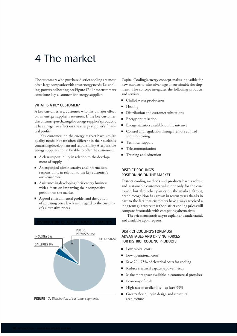
The customers who purchase district cooling are most
oten large companies with great energy needs, i.e. cool-
ing, power and heating, see Figure 17. These customers
constitute key customers or energy suppliers
whaT is a key cusTomer?
A key customer is a customer who has a major eect
on an energy supplier’s revenues. I the key customerdiscontinues purchasing the energy supplier’s products,
it has a negative eect on the energy supplier’s fnan-
cial profts.Key customers on the energy market have similar
quality needs, but are oten dierent in their outlooksconcerning development and responsibility. A responsibleenergy supplier should be able to oer the customer:
A clear responsibility in relation to the develop-ment o supply
An expanded administrative and inormationresponsibility in relation to the key customer’s
own customersAssistance in developing their energy business
with a ocus on improving their competitiveposition on the market.
A good environmental profle, and the optiono adjusting price levels with regard to the custom-er’s alternative prices.
4 The market
Capital Cooling’s energy concept makes it possible ornew markets to take advantage o sustainable develop-ment. The concept integrates the ollowing productsand services:
Chilled water production
Heating
Distribution and customer substations
Energy optimisation
Energy statistics available on the internet
Control and regulation through remote controland monitoring
Technical support
Telecommunication
Training and education
disTricT cooling’s
posiTioning on The markeTDistrict cooling methods and products have a robust
and sustainable customer value not only or the cus-
tomer, but also other parties on the market. Strong
brand recognition has grown in recent years thanks in
part to the act that customers have always received a
long term guarantee that the district cooling prices will
compare avourable with competing alternatives.The price structure is easy to explain and understand,
and available upon request.
disTricT cooling’s foremosT
advanTages and driving forcesfor disTricT cooling producTs
Low capital costs
Low operational costs
Save 20 - 75% o electrical costs or cooling
Reduce electrical capacity/power needs
Make more space available in commercial premises
Economy o scale
High rate o availability – at least 99%
Greater exibility in design and structuralarchitecturefigure 17. Distribution o customer segments.
pUBLIC
pREmISES 11%
GALLERIES 4%
INDUSTRy 3%OFFICES 82%
distribution of key customer segments

8/4/2019 Capital Cooling DCS
http://slidepdf.com/reader/full/capital-cooling-dcs 21/24 introduction – energy and district cooling 21
Environmentally compatible HCFC and CFC reealternatives
No difculties with noise and emissions
Free time to ocus on core processes/business operations
Is regulated according to need
The property owner has access to a new product(cold water) that is possible to “sell” to tenants.
successfully esTablishing disTricT cooling
Establishing new energy inrastructure products on the
market such as district cooling clearly requires knowledge
and competence. Creating a successul district cooling
project requires:
Knowing what cooling needs and quality demandsthe customers have
Make it possible to create new products and services
Understand the customer’s alternative costs
Have a unique business concept
Make it possible or the end user to ocus on hiscentral business operations
Have a clear ocus on the key customer’s needs
See problems as an opportunity to create new business
Everyone involved must be an ambassador or the project.
the history of
district coolingDistrict cooling has its roots in the
early 1800's when lans were made to distribute
clean, cold air to buildings through underground
ies. It is not now i these lans were actuallcarried out, and district cooling was not intro-duced on a ractical leel beore the ColoradoAutomatic Rerigerator Comany was established
in Dener in 1889.
man o the earlier sstes used aonia
and salt water to reeze meat and cool build-ings used by the public such as restaurants,
theatres etc.
In the 1930's large cooling systems were built
in Roceeller Centre in New yor Cit and theUnited States Caitol buildings.
1960's – The frst commercial district cooling
systems were installed in the USA in commercial
areas near cities.
1967 – Euroe receied its frst district cool-ing system. Climade began supplying district
heating and cooling to the La Déense ofce
cole in paris.1989 – Scandinaia receied its frst district
cooling sste in Baeru outside o Oslo.
1992 – västerås Energi & production initiated
the roduction o district cooling in Sweden.
1995 – District cooling was successully
established in Stockholm. Ater 5 years o de-
eloent this sste is now one o the world’slargest, most environmentally compatible and
energ eectie in the world.
The potential or district cooling that was
estiated in the 1990's or the entire countrhas now been surassed. The aount o energer ear doubled at the outset, and it currentlappears that growth will continue at about a
ace o 20% er ear. Not an business feldscan currentl atch this rate o growth. Districtcooling has been o the highest qualit since itwas introduced thanks to being able to draw uon
the more than 50 years o technical deeloment
related to the roduction o district heating anddistribution. In 2002, district cooling was sulied
to about 500 custoers with an energ olueo alost 500 GWh in Sweden alone.
district cooling systems were built in NYC as early as the 1930’s. By 2002, district cooling was being supplied to about 500
customers in a variety o countries. In Sweden alone the energy volume was almost 500 GWh.

8/4/2019 Capital Cooling DCS
http://slidepdf.com/reader/full/capital-cooling-dcs 22/24 22 introduction – energy and district cooling
noTes

8/4/2019 Capital Cooling DCS
http://slidepdf.com/reader/full/capital-cooling-dcs 23/24 introduction – energy and district cooling 23

8/4/2019 Capital Cooling DCS
http://slidepdf.com/reader/full/capital-cooling-dcs 24/24
O d e l i u s N e
w
M e d i a # 2 6 7 2
T r y c k : B l o m b e r g &
J a n s o n , 2 0 0 4