capillary flow technology - agilent · connector tube connector reliable precolumn ... 1:1 split...
TRANSCRIPT
Capillary Flow Technology
July 2007
Capillary Flow Technology-- solves difficult application problems easily & opens up
many new (and old) possibilities for GC & GC/MS
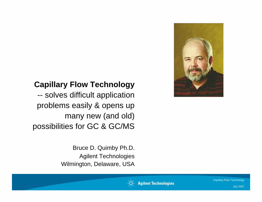
Bruce D. Quimby Ph.D.Agilent Technologies
Wilmington, Delaware, USA
Capillary Flow Technology
July, 2007Page 2
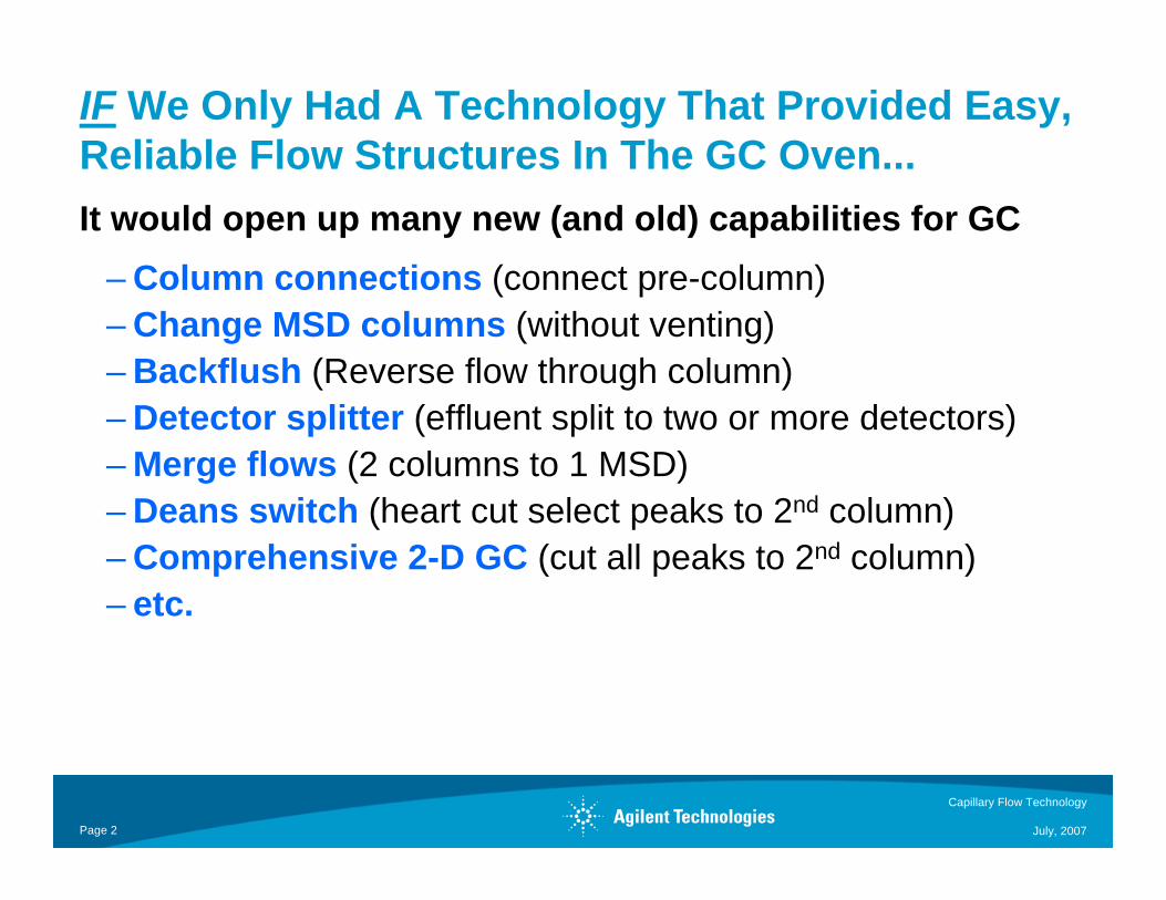
IF We Only Had A Technology That Provided Easy, Reliable Flow Structures In The GC Oven...It would open up many new (and old) capabilities for GC
– Column connections (connect pre-column) – Change MSD columns (without venting) – Backflush (Reverse flow through column)– Detector splitter (effluent split to two or more detectors)– Merge flows (2 columns to 1 MSD) – Deans switch (heart cut select peaks to 2nd column)– Comprehensive 2-D GC (cut all peaks to 2nd column) – etc.
Capillary Flow Technology
July, 2007Page 3
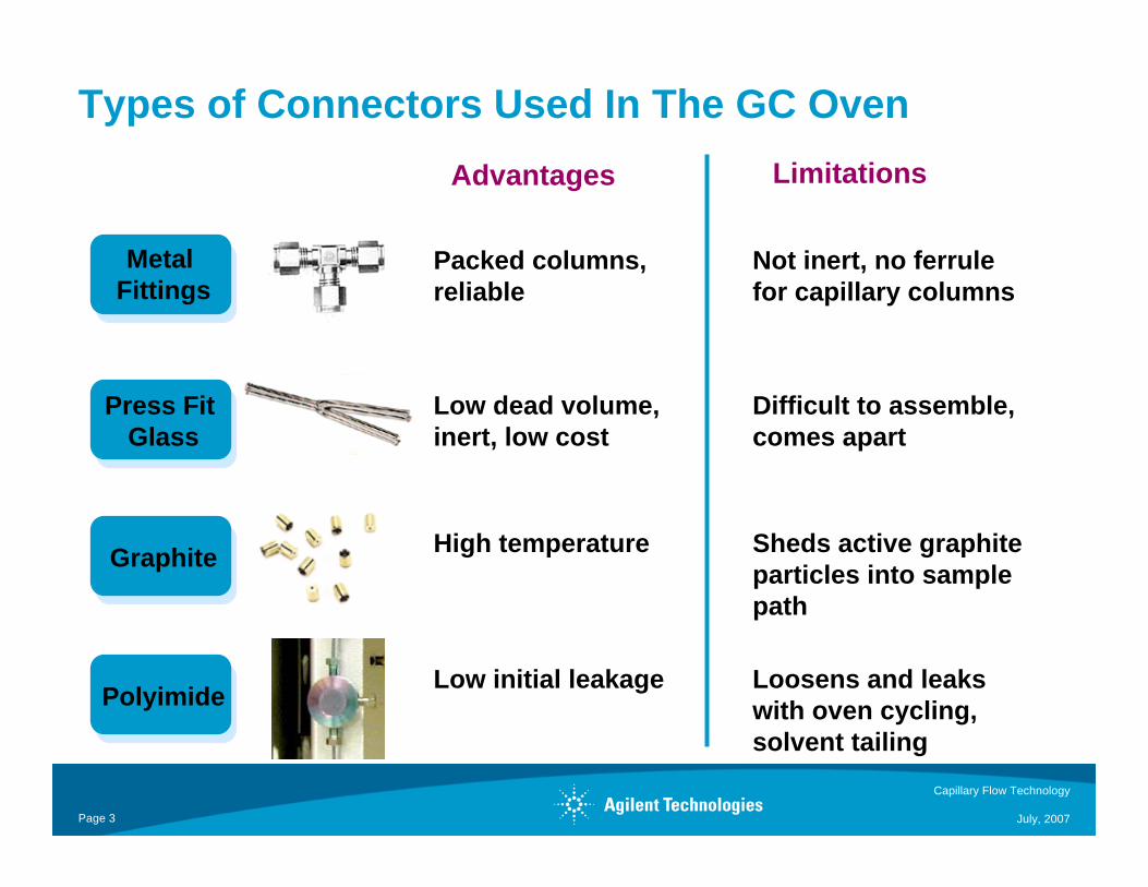
Metal Fittings
Press Fit Glass
Graphite
Polyimide
Packed columns, reliable
Low dead volume, inert, low cost
High temperature
Low initial leakage
Types of Connectors Used In The GC Oven
Not inert, no ferrule for capillary columns
Difficult to assemble, comes apart
Sheds active graphite particles into sample path
Loosens and leaks with oven cycling, solvent tailing
Advantages Limitations
Capillary Flow Technology
July, 2007Page 4
Challenges For Inside the Oven Devices
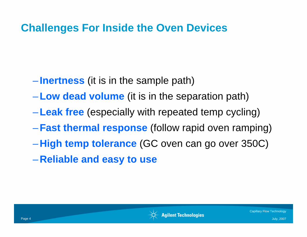
– Inertness (it is in the sample path)– Low dead volume (it is in the separation path)– Leak free (especially with repeated temp cycling)– Fast thermal response (follow rapid oven ramping)– High temp tolerance (GC oven can go over 350C)– Reliable and easy to use

Capillary Flow Technology
July, 2007Page 5
5 Key Developments in Capillary Flow Technology
Complex flow structures with low thermal mass
Makes metal surfaces as inert as column
Backflushing now possible, change MSD columns without venting, known column outlet pressure
Accurately predict flows and pressures BEFORE installing devices
Easy to use, do not loosen or leak with oven cycling to 400°C
Manifold Plates
Deactivation of Metal
EPC
Calculators
Metal Ferrules
Capillary Flow Technology
July, 2007Page 6
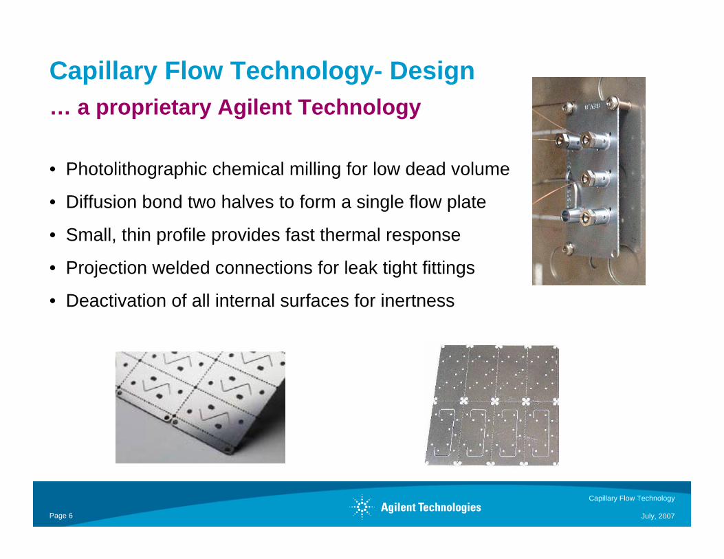
Capillary Flow Technology- Design
• Photolithographic chemical milling for low dead volume
• Diffusion bond two halves to form a single flow plate
• Small, thin profile provides fast thermal response
• Projection welded connections for leak tight fittings
• Deactivation of all internal surfaces for inertness
… a proprietary Agilent Technology
Capillary Flow Technology
July, 2007Page 7
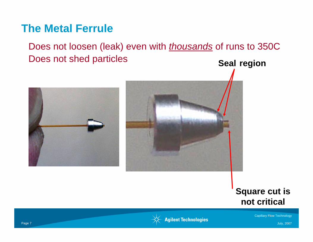
The Metal Ferrule
Square cut is not critical
Seal region
Does not loosen (leak) even with thousands of runs to 350CDoes not shed particles
Capillary Flow Technology
July, 2007Page 8
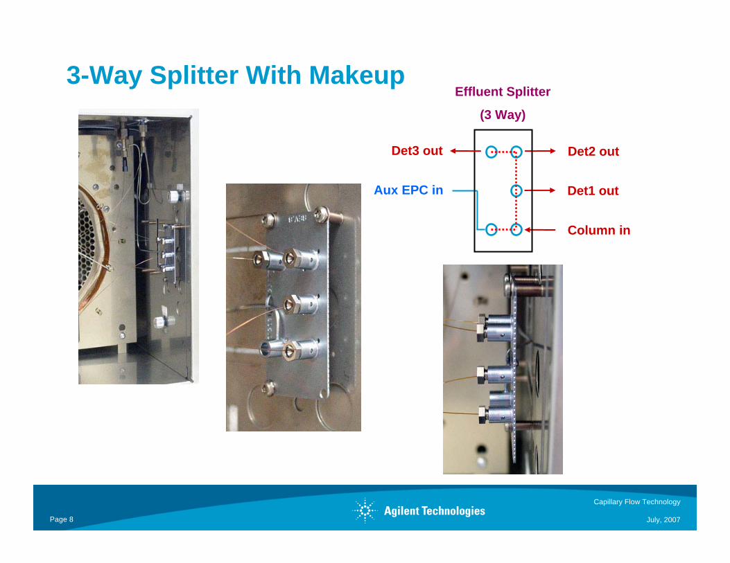
3-Way Splitter With MakeupEffluent Splitter
(3 Way)
Column in
Aux EPC in Det1 out
Det2 outDet3 out
Capillary Flow Technology
July, 2007Page 9
Capillary Flow Technology
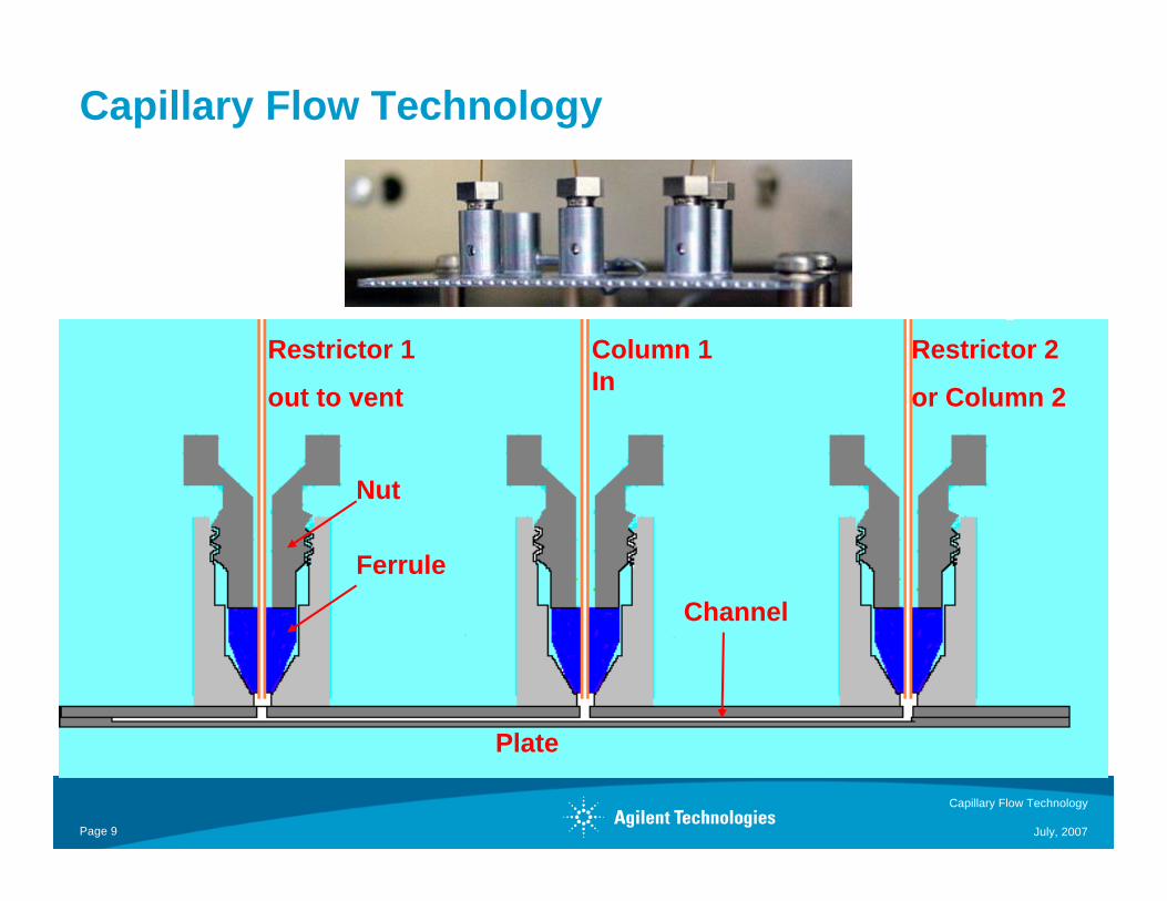
Column 1 In
Restrictor 1
out to vent
Plate
Ferrule
Nut
Restrictor 2
or Column 2
Channel
Capillary Flow Technology
July, 2007Page 10
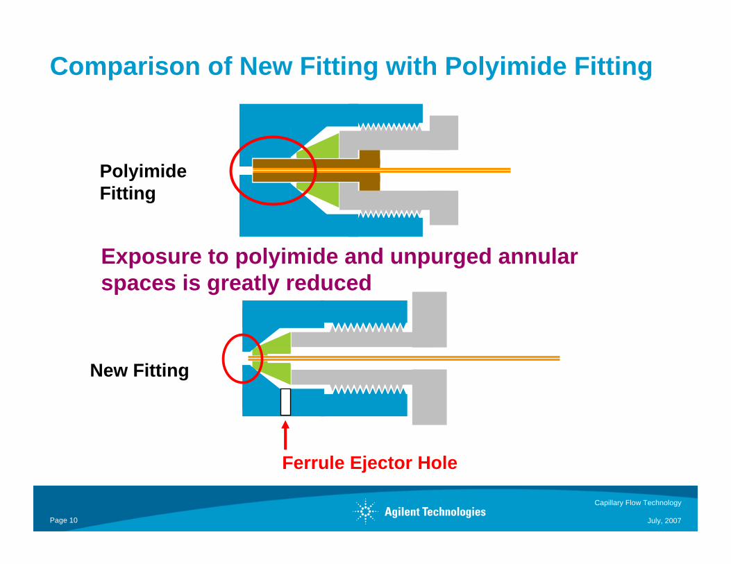
Comparison of New Fitting with Polyimide Fitting
Polyimide Fitting
New Fitting
Exposure to polyimide and unpurged annular spaces is greatly reduced
Ferrule Ejector Hole
Capillary Flow Technology
July, 2007Page 11
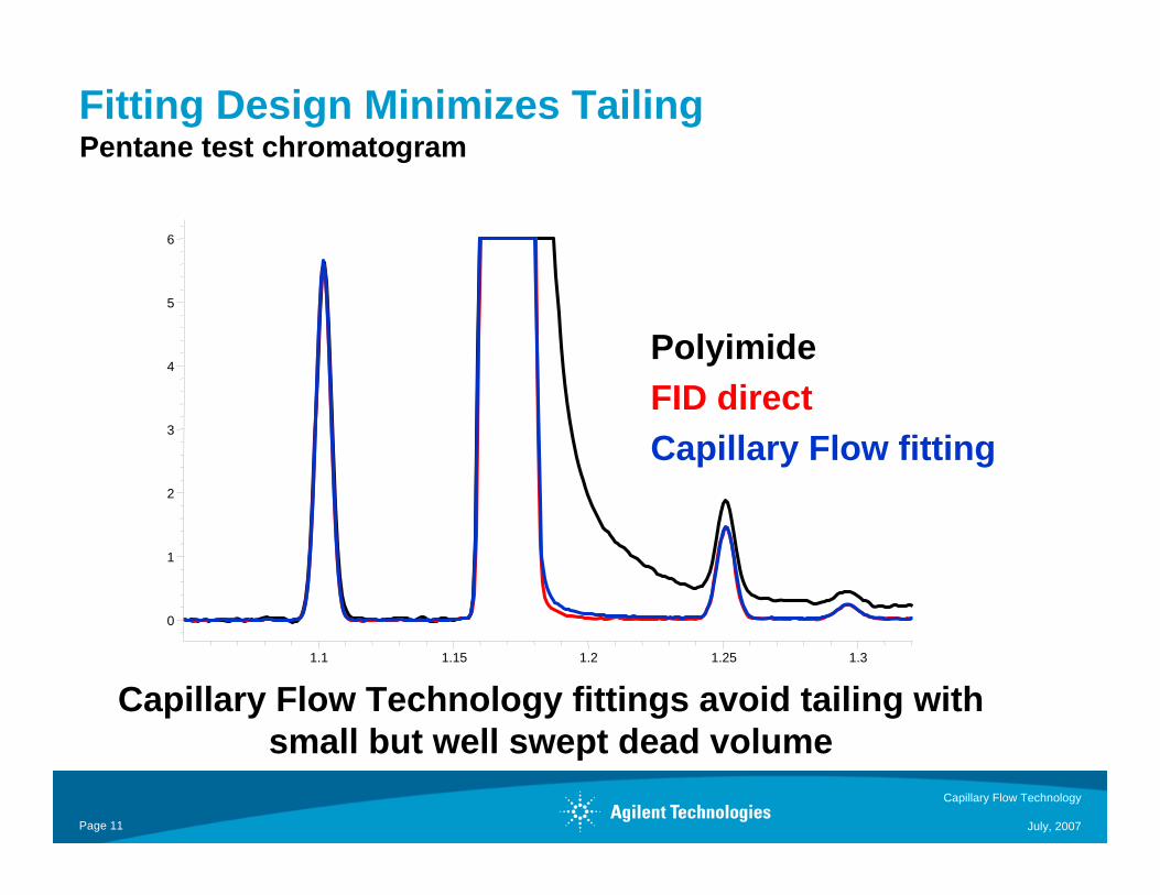
PolyimideFID directCapillary Flow fitting
Capillary Flow Technology fittings avoid tailing with small but well swept dead volume
1.1 1.15 1.2 1.25 1.3
0
1
2
3
4
5
6
Pentane test chromatogramFitting Design Minimizes Tailing
Capillary Flow Technology
July, 2007Page 12
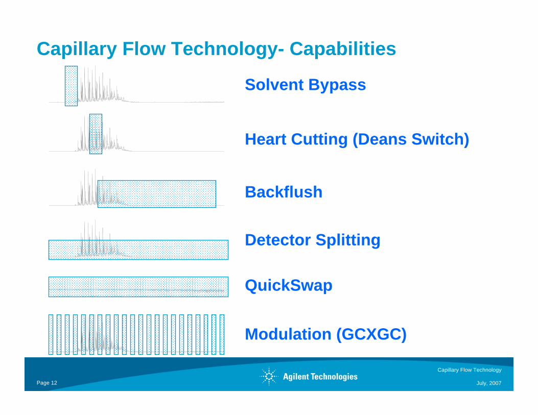
Capillary Flow Technology- Capabilities
Detector Splitting
Solvent Bypass
Heart Cutting (Deans Switch)
QuickSwap
Modulation (GCXGC)
Backflush
Capillary Flow Technology
July, 2007Page 13
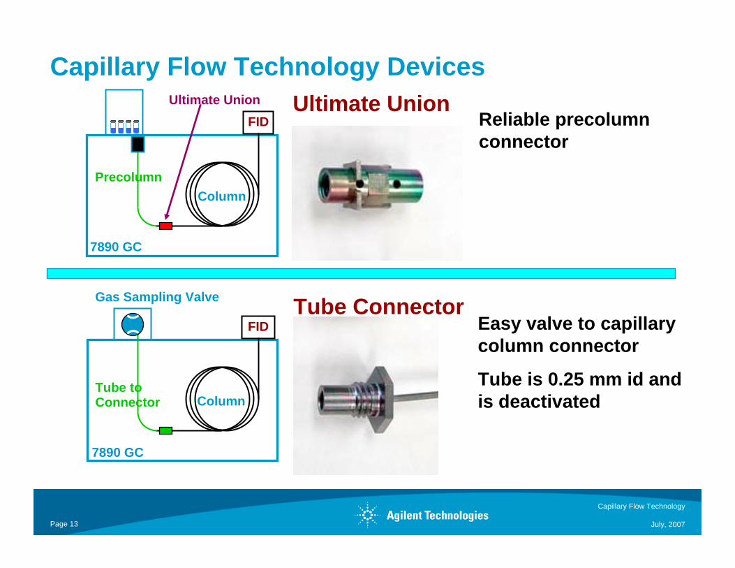
Capillary Flow Technology DevicesUltimate UnionUltimate Union
7890 GC
Column
FID
Precolumn
Gas Sampling Valve
7890 GC
Column
FID
Tube to Connector
Tube Connector
Reliable precolumn connector
Easy valve to capillary column connector
Tube is 0.25 mm id and is deactivated

Capillary Flow Technology
July, 2007Page 14
Splitters: Unpurged Tee
1:1 split FPD:uECD
Effluent Splitter WITHOUT Makeup
Auto-sampler
7890A GC
Column
0.3 m X 0.25 mm id
30 m X 0.25 mm id X 0.25 um HP-5MS
FPD P
μECD
Simultaneous detection with 2 detectors (but NOT MSD)Cannot do backflushing
Det 2 OUT
Column IN
Det 1 OUT
Capillary Flow Technology
July, 2007Page 15
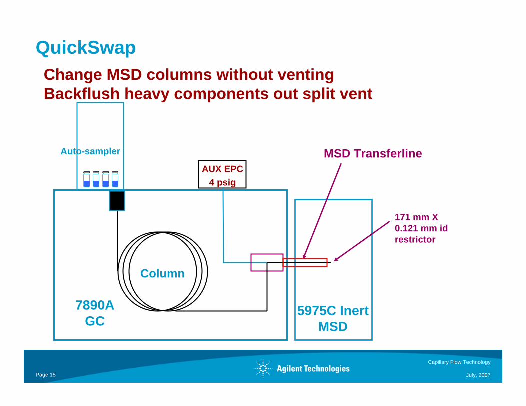
QuickSwap
MSD TransferlineAuto-sampler
7890A GC
Column
AUX EPC4 psig
171 mm X 0.121 mm id restrictor
5975C InertMSD
Change MSD columns without ventingBackflush heavy components out split vent
Capillary Flow Technology
July, 2007Page 16
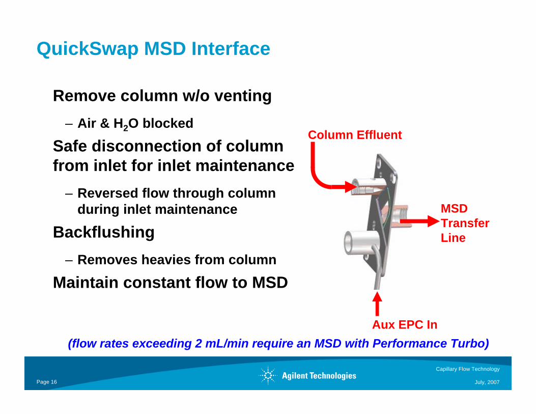
QuickSwap MSD Interface
Remove column w/o venting– Air & H2O blocked
Safe disconnection of column from inlet for inlet maintenance
– Reversed flow through column during inlet maintenance
Backflushing– Removes heavies from column
Maintain constant flow to MSD
(flow rates exceeding 2 mL/min require an MSD with Performance Turbo)
MSD TransferLine
Aux EPC In
Column Effluent
Capillary Flow Technology
July, 2007Page 17
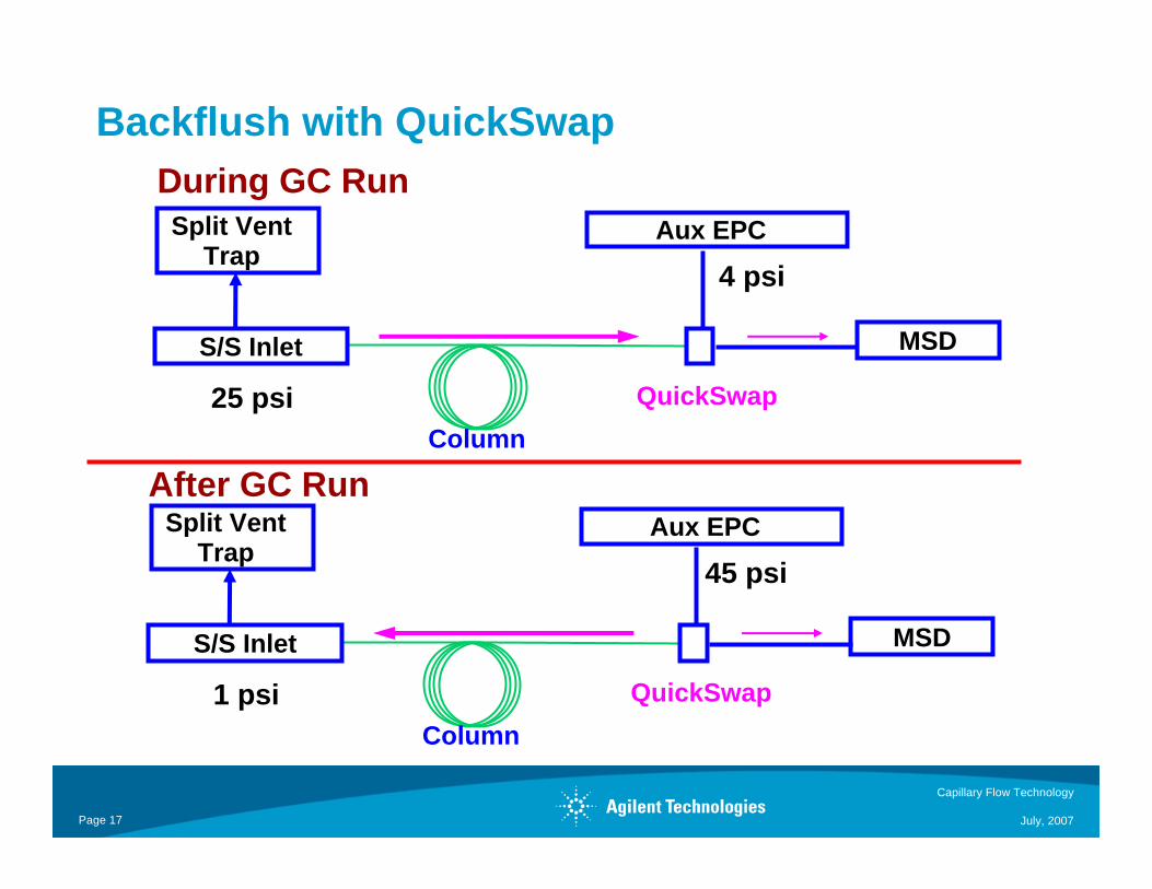
Backflush with QuickSwap
S/S Inlet
QuickSwapColumn
1 psi
45 psi
MSD
Aux EPCSplit Vent Trap
During GC Run
After GC Run
S/S Inlet
QuickSwapColumn
25 psi
4 psi
MSD
Aux EPCSplit Vent Trap

Capillary Flow Technology
July, 2007Page 18
Benefits of Backflushing
– More samples/day/instrument– Better quality data– Lower operating costs– Less frequent and faster GC & MSD maintenance– Longer column life– Less chemical background
Capillary Flow Technology
July, 2007Page 19
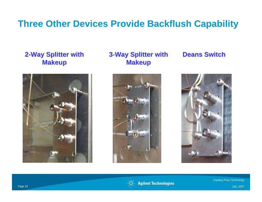
Three Other Devices Provide Backflush Capability
22--Way Splitter with Way Splitter with MakeupMakeup
33--Way Splitter with Way Splitter with MakeupMakeup
Deans SwitchDeans Switch
Capillary Flow Technology
July, 2007Page 20
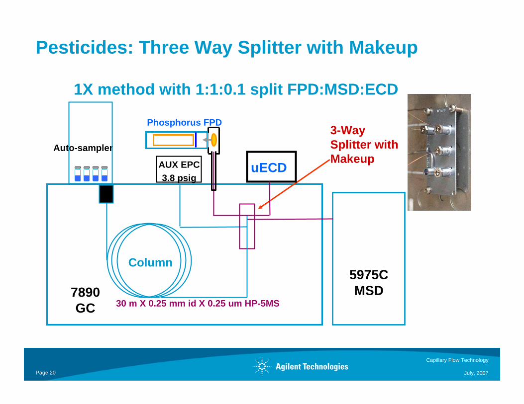
Pesticides: Three Way Splitter with Makeup
1X method with 1:1:0.1 split FPD:MSD:ECD
3-Way Splitter with Makeup
Auto-sampler
7890GC
Column
Phosphorus FPD
30 m X 0.25 mm id X 0.25 um HP-5MS
5975C MSD
uECDAUX EPC3.8 psig

Capillary Flow Technology
July, 2007Page 21
Full scan TIC
SIM
µECD
5.00 10.00 15.00 20.00 25.00 30.00 35.00 40.00
FPD(P)
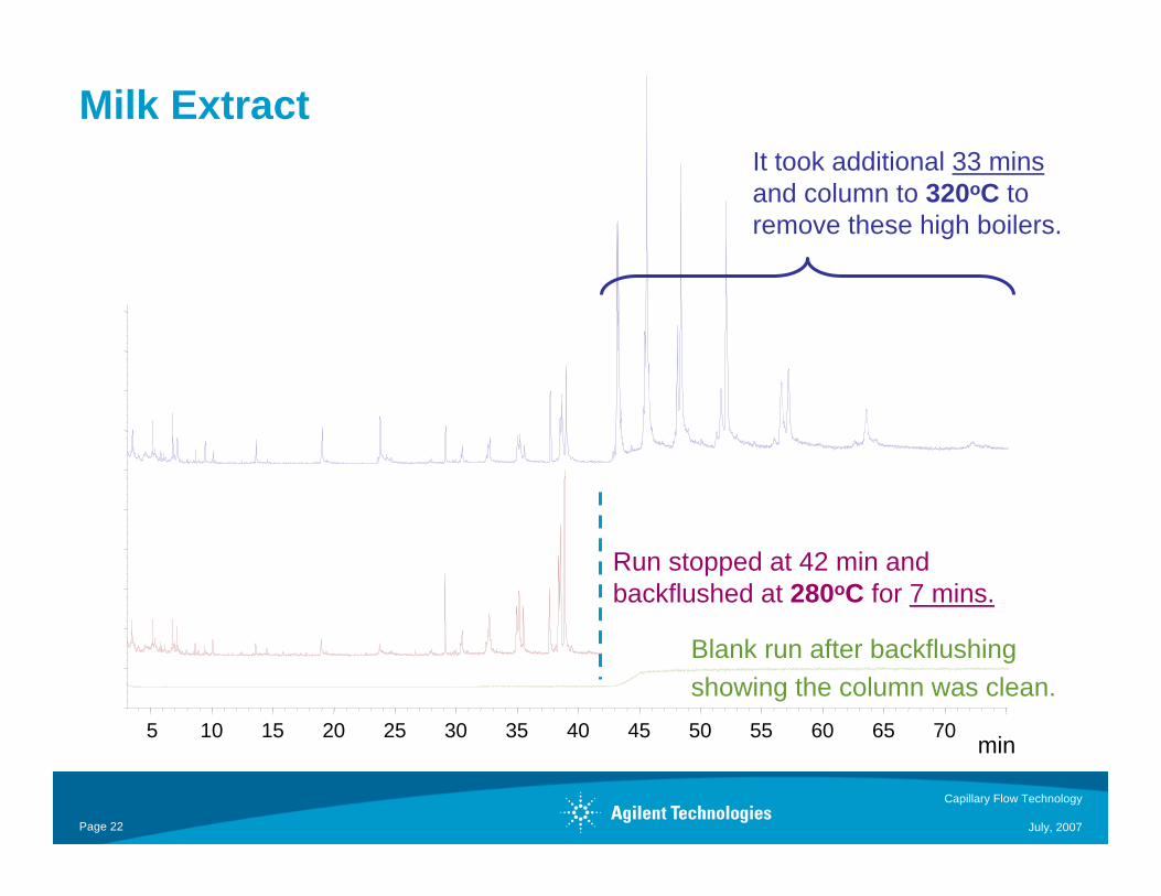
Milk Extract (1 injection)
Capillary Flow Technology
July, 2007Page 22
5 10 15 20 25 30 35 40 45 50 55 60 65 70
Run stopped at 42 min and backflushed at 280oC for 7 mins.
It took additional 33 minsand column to 320oC to remove these high boilers.
Blank run after backflushing
min
showing the column was clean.
Milk Extract
Capillary Flow Technology
July, 2007Page 23
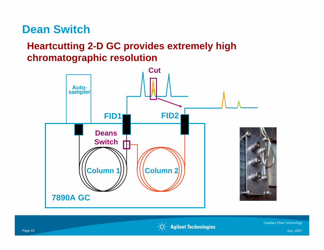
Dean Switch
Cut
Deans Switch
Auto-sampler
7890A GC
FID1 FID2
Column 1 Column 2
Heartcutting 2-D GC provides extremely high chromatographic resolution
Capillary Flow Technology
July, 2007Page 24
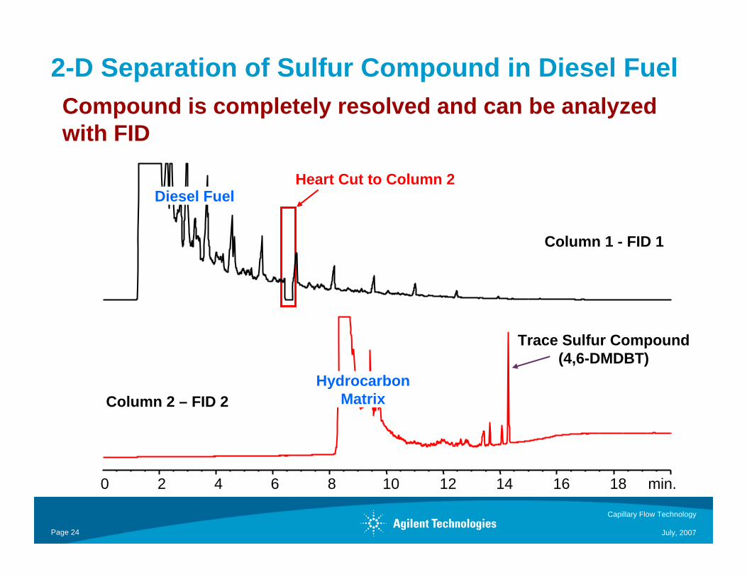
Heart Cut to Column 2
Trace Sulfur Compound(4,6-DMDBT)
Column 1 - FID 1
Column 2 – FID 2
0 2 4 6 8 10 12 14 16 18 min.
HydrocarbonMatrix
Diesel Fuel
2-D Separation of Sulfur Compound in Diesel FuelCompound is completely resolved and can be analyzed with FID
Capillary Flow Technology
July, 2007Page 25
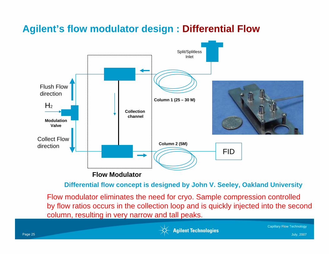
Agilent’s flow modulator design : Differential Flow
ModulationValve
FID
Split/SplitlessInlet
Column 1 (25 – 30 M)
Column 2 (5M)
Collection channel
Flow Modulator
H2
Flush Flowdirection
Collect Flow direction
Flow modulator eliminates the need for cryo. Sample compression controlledby flow ratios occurs in the collection loop and is quickly injected into the second column, resulting in very narrow and tall peaks.
Differential flow concept is designed by John V. Seeley, Oakland University
Capillary Flow Technology
July, 2007Page 26
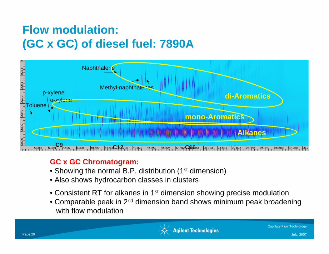
Flow modulation:(GC x GC) of diesel fuel: 7890A
GC x GC Chromatogram:• Showing the normal B.P. distribution (1st dimension)• Also shows hydrocarbon classes in clusters
• Consistent RT for alkanes in 1st dimension showing precise modulation• Comparable peak in 2nd dimension band shows minimum peak broadening
with flow modulation
Naphthalene
Toluene
p-xyleneo-xylene
C9 C12 C16
Alkanes
mono-Aromatics
di-AromaticsMethyl-naphthalenes
Capillary Flow Technology
July, 2007Page 27
Agilent Flow Modulation GC x GC
• Reliable Setup: Based on capillary-flow- technology, easy to setup, high
performance chromatography, and reliable.
• No Cryogen Required: Flow modulation means no tanks of Liquid N2 or CO2
• 7890A Enabled GC x GC: Capillary- flow-technology ready, synchronized
periodic events ensure precise modulation, control from a modified TCD board
• Comparable resolution without N2: Cap Flow Technology allows low dead
volume and precise flow control, resulting in minimum peak broadening even without
cryo-focusing . Peak widths on the second column are typically 70 to 100 ms at half
maximum.
• Sensitivity: Approaches that obtained by thermally modulated systems
Capillary Flow Technology
July, 2007Page 28
Capillary Flow Technology solves difficult application problems easily.
It opens up many new (and old) possibilities for GC and GC/MS
systems.
Summary