capacitive level switches - home | isi control … level switch... · hycontrol me capacitive level...
TRANSCRIPT

Capacitive switch catalogue HYC-CSC01 Elect. Iss. 01
CAPACITIVE LEVEL SWITCHES

CAPACITIVE SWITCH FEATURES
HYCONTROL CAPACITIVE LEVEL SWITCH RANGE
1
Hycontrol ME capacitive level switches provide simple, accurate and reliable level control for a wide range of applications. They are suitable for use on liquids, solids, slurries, pastes, granules, powders and pellets in high temperature, high pressure and corrosive environments.
Unlike some other capacitive switches, this unit works independently of the tank walls using an integral grounding sleeve without the need for a reference probe, which enables it to be used in concrete, plastic or other non metalic tanks.
This technology also provides an ideal solution for interface detection applications such as oil on water and liquid detection underneath a layer of foam.
• Easy installation through a 1” BSP process fitting
• High corrosion and chemical resistance as standard options
• Universal design can be used for high or low level detection
• Multiple versions with rod and cable to simplify mounting options
• High temperature versions up to 800 °C
• Low maintenance technology with no moving parts
• Hazardous area certified versions ATEX approved
• Adjustable sensitivity for a wide range of products
• Adjustable time delay to stop spurious signals from surface ripple
• Anti-static probes for plastic pellet applications with high static probability
• Remote electronics option for high vibration applications
• Interface level detection for difficult applications
CONSTRUCTION
1. Probe : 304SS or 316SS
2. Insulation UPE or PTFE
3. Grounding Sleeve
4. Connection 1" BSP standard
:
: 304SS or 316SS
:
5. Housing : Aluminum IP65 epoxy coated
6. Conduit entry : ½" BSP
7. Housing O-Ring : NBR
8. PC board : A, B, C, D Type
9. Sensitivity adjustment : 10pF, 20pF, 40pF
10. Cover : Aluminum epoxy coated

[ STANDARD TYPE ] [ STANDARD TYPE ]
-20°C~80°C -20°C~80°C
ME10 A/B/C ME11 A/B/C
Aluminum IP65
304SS 304SS
UPE UPE
1"BSP 1"BSP
10pF, 20pF, 40pF 10pF, 20pF, 40pF
Approx. 1.9kg Approx. 1.9kg
Operating Temp.
Model
Dimension
Enclosure details
Probe Material
Insulation Material
Connection
Sensitivity Range
Weight
SupplyVoltage
Delay Time
Power Consumption
Contact Rating
110/220VAC ±10% or 24VDC
0~6 seconds
2W
[ HI-TEMP. TYPE ]
-20°C~200°C
ME20 A/B/C
304SS
PTFE
1"BSP
10pF, 20pF, 40pF
Approx. 2.4kg
5A/240VAC or 5A/30VDC, SPDT or NPN 100mA
STANDARD GENERAL PURPOSE VERSIONS
Ø21
1"
1/2"BSP
1/2"BSP
25
402
250(L...)
80
50
120
Ø12.7
Ø118
3021"
Ø27
50
50 150(L...)
25
50
Ø18
material
UPEmaterial
UPE
Ø21
1"
1/2"BSP
Ø118
Ø8860
25
46280
50250(L...)
120
Ø12.7
material
PTFE
2

-20°C~800°C
ME28 A/B/C
304 SS
CERAMIC
10pF, 20pF
110/220VAC±10% or 24VDC
0~6 seconds
2W
2 2"x5kg/cm JIS Flange
Operating Temp.
Model
Dimension
Probe Material
InsulationMaterial
Connection
Sensitivity Range
Weight
Delay Time
Power Consumption
Contact Rating
[ HI-TEMP. ]
-20°C~80°C
[ CORROSION-PROOF ]
ME30 A/B/C
304 SS
Wetted part: UPE coating
10pF
2 1-1/2"x10kg/cm JIS Flange (UPE)2 1-1/2"x10kg/cm JIS Flange (SS)
Approx. 2kgApprox. 6.5kg
Aluminum IP65
-20°C~120°C
ME32 A/B/C
Wetted part: PVDF coating
UPE
10pF, 20pF
Depends on the length
with PVDF Washer (5mm)
[ CORROSION-PROOF ]
HIGH TEMPERATURE AND CORROSION RESISTANT VERSIONS
SupplyVoltage
1/2"BSP
Ø55
250
40
40
330(L...)
145
620
PCD105
4- Ø15
Ø28
12
Ø118
Ø130
material
CERAMIC
Ø140
1/2"BSP
Ø40
255(L...)
41325
Ø118
PCD105
4- Ø19
material
UPE
1/2"BSP
Ø118
4- Ø19PCD105
L
Ø25
Ø140
material
PVDFmaterial
UPE
3
5A/240VAC or 5A/30VDC, SPDT or NPN 100mA
(SS)
Enclosure details

110/220VAC±10% or 24VDC
0~6 seconds
2W
Operating Temp.
Model
Dimension
Enclosure details
Probe Material
Insulation Material
Connection
Sensitivity Range
Weight
Delay Time
Power Consumption
Contact Rating
-20°~100°C
ME40 A/B/C
304 SS
UPE
10pF
1"BSP (SS)
[ REMOTE PROBE TYPE ]
Approx. 3kg
Aluminum IP65
-20°C~80°C
ME50 A/B/C
UPE
10pF, 20pF, 40pF
304 SS cable
1"BSP (SS)
[ WIRE-PROBE TYPE ]
Approx. 4.1kg
-20°C~80°C
ME60 A/B/C
304 SS
UPE
10pF, 20pF, 40pF
2 2-1/2"x 5kg/cm JIS Flange (SS)
[ PLATE TYPE ]
Approx. 3.2kg
REMOTE AND CABLE VERSIONS
SupplyVoltage
STD.:1.8MMax.:5M
1/2"BSP1"
Ø65
25
Ø21
80
50
120
Ø12.7
356
250(L...)
2- Ø7.5
112
195
Deep = 77
material
UPE
Ø9
1/2"BSP
1"
Ø28
70
50
80Ø21
25
Ø118
290
3M(L...)
150M8
material
UPE
1/2"BSP
189
150
Ø118
Ø155
Ø130
Ø75 Ø96
4-Ø15
material
UPE
4
5A/240VAC or 5A/30VDC, SPDT or NPN 100mA

ATEX EEx ia IIC (¤)
2W
Operating Temp.
Model
Dimension
Enclosure details
Probe Material
Insulation Material
Connection
EnclosureProtection
Sensitivity Range
Weight
Power Consumption
Contact Rating
NPN 100mA
-20°C~80°C
ME70D (with EX-75U) ME72D (with EX-75U)
304 SS / 316 SS 304 SS / 316 SS
PTFE or UPE PTFE or UPE PTFE or UPE
10pF, 20pF, 40pF
1"BSP (SS)
[ STANDARD TYPE ]
Approx. 1.9kg
[ HI-TEMP. TYPE ]
-20°C~200°C
1"BSP (SS)
10pF, 20pF, 40pF
Approx. 2.4kg
16~24VDC
INTRINSICALLY SAFE VERSIONS FOR HAZARDOUS AREAS
-20°C~80°C
10pF, 20pF, 40pF
304 SS / 316 SS cable
1"BSP (SS)
[ WIRE-PROBE TYPE ]
Approx. 4.1kg
ME75D (with EX-75U)
Aluminum IP65
SupplyVoltage
Ø21
1/2"BSP
1"
Ø12.7120
250(L...)50
80402
25
Ø118
material
PTFE
Ø21
1"
1/2"BSP
Ø118
Ø8860
25
46280
50250(L...)
120
Ø12.7
material
PTFE
Ø9
1/2"BSP
1"
Ø28
70
50
80Ø21
25
Ø118
290
3M(L...)
150M8
material PTFE
5
(¤) For ATEX approvals contact the office

Operating Temp.
Model
Dimension
Enclosure details
Probe Material
Insulation Material
Connection
Sensitivity Range
Weight
Power Consumption
Contact Rating
-20°C~200°C
10pF, 20pF
PTFE or UPE coating PTFE or UPE coating
1"BSP (SS)
[ ANTI-STATIC TYPE ] HI-TEMP.
Approx. 3.1kg
-20°C~80°C
10pF, 20pF, 40pF
2 2-1/2"x 5kg/cm JIS Flange (SS)
[ PLATE TYPE ]
Approx. 3.2kg
ME76D (with EX-75U) ME77D (with EX-75U)
2W
NPN 100mA
16~24VDC
Aluminum IP65
-20°C~80°C
10pF, 20pF
1"BSP (SS)
[ ANTI-STATIC TYPE ]
Approx. 2kg
ME78D (with EX-75U)
304 SS / 316 SS
PTFE or UPE PTFE or UPE PTFE or UPE
EnclosureProtection
SupplyVoltage
1/2"BSP
189
150
Ø118
Ø155
Ø130
Ø75 Ø96
4-Ø15
material
UPE
1"
Ø21
Ø118
60Ø88
1/2"BSP
47280
260(L...)
25
material
PTFEØ21
260(L...)
41280
251"PT
1/2"BSP
Ø118
material PTFE
6
(¤) For ATEX approvals contact the office
ATEX EEx ia IIC (¤)
INTRINSICALLY SAFE VERSIONS FOR HAZARDOUS AREAS

Operating Temp.
Model
Dimension
Enclosure details
Probe Material
Insulation Material
Connection
Sensitivity Range
Weight
Delay Time
Power Consumption
Contact Rating
-20°C~80°C
ME80 A/B/C
10pF, 20pF
UPE coating
UPE
1"BSP (SS)
[ ANTI-STATIC TYPE ]
Approx. 2kg
-20°C~200°C
ME81 A/B/C
10pF, 20pF
PTFE coating
PTFE
1"BSP (SS)
[ ANTI-STATIC TYPE ] HI-TEMP.
Approx. 2.5kg
0~6 seconds
2W
Aluminum IP65
ANTI-STATIC AND TEFLON PROBE VERSIONS
110/220VAC±10% or 24VDCSupplyVoltage
Ø21
260(L...)
41280
25
1"
1/2"BSP
Ø118
1"
Ø21
Ø118
60Ø88
1/2"BSP
47280
260(L...)
25
material UPE material
PTFE
7
5A/240VAC or 5A/30VDC, SPDT or NPN 100mA

75
0V
0V
18VDC
INPUT
COM
NC NO110V
220V
110
45
Ex-75U
PWR
ON
1. Supply voltage :
2. Power consumption : 2W
3. Input signal : NPN transistor
4. Output voltage :
5. Short circuit current :
6. Relay output :
7. Operating temp.
8. Weight
110 / 220VAC
resistance Ri= 500W
16~24 VDC
25mA max.
SPDT 10A /30VDC 10A /220VAC
: -20°C ~ 60°C
: 0.3 kg
9. Enclosure mounting : DIN Rail
EX-75U Zener barrier provides intrinsic safety to the ME7•D type level switch by limiting thecurrent from the control module in the safe area to the level switch in the hazardous zoned area.Please contact the office for a copy of the certificates and more information if required.
HAZARDOUS AREA INTRINSICALLY SAFE VERSION
8
16
VD
C
IN
EX
-75
U
Remote Control Room
(Hazardous area)ME7 series
Wall
AWG 18x3C wire
(Non-hazardous safe area)
EX-75U
WIRING CONFIGURATION(Refer to page 12)
Hycontrol level switches must be installed and wired in accordance with the appropriate National Standards concerning installation in hazarous environments.

COARSE CALIBRATION
SENSITIVITY ADJUSTMENT
DELAY FUNCTION SETTING
With the probe in contact with the material being detected, set the SENSITIVITY ADJ pointer to position H and then using a blade screwdriver set the COARSE adjustment until the INDICATOR lamp is on. Rotating the COARSE adjustment clockwise and counter-clockwise will turn the INDICATOR lamp on and off. Ensure the lamp is on before moving on to adjusting the sensitivity.
This feature is used to stop any spurious signals to the switch from surface ripple or agitation of the product. It also protects the relay from premature wear by eliminating contact chatter by adding a small time delay from when product contacts the probe .
The factory setting is zero seconds with the DELAY screw fully counter clockwise. Turning the screw in a clockwise direction introduces a delay between the INDICATOR lamp coming on and the relay changing its state.
After setting the COARSE calibration the INDICATOR lamp will switch on when probe is touching the material and off when in free air.Make sure the probe is in contact with the material and then turn the SENSITIVITY ADJ knob clockwise until the INDICATOR lamp turns off. Set the SENSITIVITY ADJ pointer half way between H and the point that the INDICATOR lamp switches off.
60
S C A BE
COARSE
80
H
90
70
110V 220V0V
DELAY
INDICATOR
ME-40-
LEVEL SENSOR
SENSITIVITY ADJ.
SERIES No.
SENSITIVITY-No.
20
L
10
405030
To sensorcoaxial cableC=120 ~ 135 Common
Normally closed
Power
Source
Normally open
Earth wire
Remote Probe Type (ME40 A/B/C)
INDICATOR
SERIES No.
COARSE
H L DELAY
SENSITIVITY ADJ
8090
70
ME-TYPE LEVEL SENSOR
405060
2010
30 SENSITIVITY-No.
AC0V 110V 220VCOMNC NO
Common
Normally closed
Power
Source
Normally open
ME10,20,30,50,60,70,80 A/B/C/D
ADJUSTMENT
9

The grounding sleeve must be mounted to protrude at least 30mm from the vessel wall.
For the ME60 type to be mounted properly the vessel
not exceed 25mm walls should thickness.
To prevent false readings on sol-ids applications it is best to make sure the material flows symmetrically. If the inlet is not located in the centre portion of the tank roof, check the flow pat-tern (a angle) of your material and place the probe in the Appropriate location.
If the probe is mounted on the top, make sure the length of probe is enough to touch the highest level of raw material.The ME50 type must have at least 300mm from the silo wall.The ME60 type is usually Located at the lower position.
For Non-Stationary or material that will be vibrated a separate control unit such as the ME40 type is recommended.
Where possible install the probe away from the inlet to re-duce the risk of inflowing mate-rial damaging the probe. If the probe is near an inlet, we rec-ommend placing a protective cover 200mm above the probe. The cover should be parallel to the probe and the same length .
L>30mm
25mm max.
Ø100
L
Process connection
ME11 ME60
A
A
A
B
B
B
ME40
300mm
ME60
ME50
a
INSTALLATION GUIDE
10
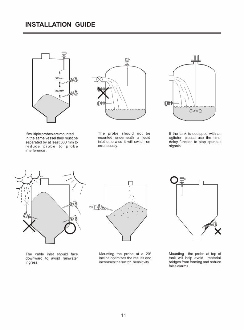
If multiple probes are mountedIn the same vessel they must be separated by at least 300 mm to r e d u c e p r o b e t o p r o b e interference .
The cable inlet should face downward to avoid rainwater ingress.
The probe should not be mounted underneath a liquid inlet otherwise it will switch on erroneously.
Mounting the probe at top of tank will help avoid material bridges from forming and reduce false alarms.
Mounting the probe at a 20° incline optimizes the results and increases the switch sensitivity.
20L
300mm
300mm
If the tank is equipped with an agitator, please use the time-delay function to stop spurious signals
INSTALLATION GUIDE
11

ME-••-D
ME-••-BDC24V Relay output
ME-••-A
ME-••-CIntrinsically safe Control unit output
DC24V Transistor npn output
0V
0V18VDCINPUT
COMNC
NORELAY OUTPUT
AC SUPPLY100V220V
0V 18V OUT
EX-75UExternal power supply
0 0 110 24220
0V 24V OUT
R 0V
+24VDC
ORDER INFORMATION
A---110/220VAC
B---DC24V, Relay output
C---DC24V, NPN transistor output
D---Designed for use with EX-75U
10 --- Standard Type
20 --- Hi-temp. Type
30 --- Corrosion Proof Type
40 --- Remote Probe Type
50 --- Wire Probe Type
60 --- Plate Type
70 --- Hazardous Area Type
80 --- Anti-static Type
Probe Length (mm)
Model
Connection
Terminal Arrangement
•Tolerance of the total product length is ±5mm.
•Characteristics, specifications and dimensions are subject to change without notice.
•Please contact Hycontrol if you have a special request not mentioned in the above
•
•
•
Flange / screw
C---3/4" (20mm)
D---1" (25mm)
E---1-1/2"(40mm)
F---2" (50mm)
G---2-1/2"(65mm)
H---3" (80mm)
I ---4" (100mm)
J---5" (125mm)
K---6" (150mm)
S---Others (please consult office with your requirements)
flange rating2
M---JIS 5kg/cm2N---JIS 10kg/cm
O---ANSI 150 Lbs
P---ANSI 300 Lbs
Q---PT
R---PF
T---BSP
S---Others
L---NPT
W---PN 10
X---PN 16
Y---PN 25
Z---PN 40
12
ME 0 02 51 0 A D T
110V/220VAC Relay output
HYCONTROL LEVEL TECHNOLOGIES
(12)
(7)
(1) (2)
(6)
(5)
(4)
(3)
(11)(10)
(9)(8)
(13)
(14)
(15)
(17) (16)
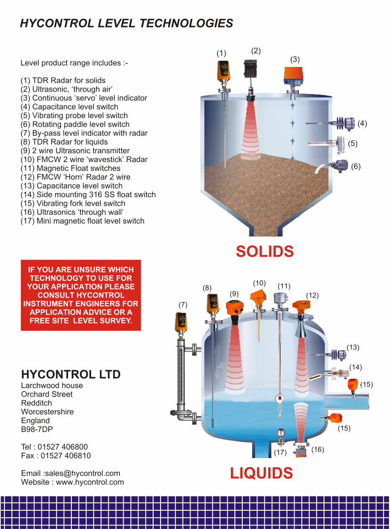
Level product range includes :-
(1) TDR Radar for solids(2) Ultrasonic, ‘through air’(3) Continuous ‘servo’ level indicator(4) Capacitance level switch(5) Vibrating probe level switch(6) Rotating paddle level switch (7) By-pass level indicator with radar(8) TDR Radar for liquids(9) 2 wire Ultrasonic transmitter(10) FMCW 2 wire ‘wavestick’ Radar(11) Magnetic Float switches(12) FMCW ‘Horn’ Radar 2 wire(13) Capacitance level switch(14) Side mounting 316 SS float switch(15) Vibrating fork level switch(16) Ultrasonics ‘through wall’(17) Mini magnetic float level switch
HYCONTROL LTDLarchwood houseOrchard StreetRedditchWorcestershireEnglandB98-7DP
Tel : 01527 406800Fax : 01527 406810
Email :[email protected] : www.hycontrol.com
IF YOU ARE UNSURE WHICH TECHNOLOGY TO USE FOR
YOUR APPLICATION PLEASE CONSULT HYCONTROL
INSTRUMENT ENGINEERS FOR APPLICATION ADVICE OR A FREE SITE LEVEL SURVEY.
LIQUIDS
(15)
SOLIDS