cap 1 ccna 2
TRANSCRIPT
Modern networks continue to evolve to keep pace with the changing way organizations carry out their daily business. Users now expect instant access to company resources from anywhere and at any time. These resources not only include traditional data but also video and voice. There is also an increasing need for collaboration technologies that allow real-time sharing of resources between multiple remote individuals as though they were at the same physical location.
Different devices must seamlessly work together to provide a fast, secure, and reliable connection between hosts. LAN switches provide the connection point for end users into the enterprise network and are also primarily responsible for the control of information within the LAN environment. Routers facilitate the movement of information between LANs and are generally unaware of individual hosts. All advanced services depend on the availability of a robust routing and switching infrastructure on which they can build. This infrastructure must be carefully designed, deployed, and managed to provide a necessary stable platform.
This chapter begins an examination of the flow of traffic in a modern network. It examines some of the current network design models and the way LAN switches build forwarding tables and use the MAC address information to efficiently switch data between hosts
Introduction
Introduction
Sent or Received Instructions
Individually, or in groups (per the instructor’s decision), discuss various ways hosts send and receive data, voice, and streaming video.
Develop a matrix (table) listing network data types that can be sent and received. Provide five examples.
Note: For an example of the matrix, see the document prepared for this modeling activity.
Save your work in either hard- or soft-copy format. Be prepared to discuss your matrix and statements in a class discussion

LAN Design
Converged Networks
Our digital world is changing. The ability to access the Internet and the corporate network is no longer confined to physical offices, geographical locations, or time zones. In today’s globalized workplace, employees can access resources from anywhere in the world and information must be available at any time, and on any device, as shown in Figure 1. These requirements drive the need to build next-generation networks that are secure, reliable, and highly available.
These next generation networks must not only support current expectations and equipment, but must also be able to integrate legacy platforms. Figure 2 shows some common legacy devices that must often be incorporated into network design. Figure 3 illustrates some of the newer platforms (converged networks) that help to provide access to the network anytime, anywhere, and on any device.

LAN Design
Converged Networks
To support collaboration, business networks employ converged solutions using voice systems, IP phones, voice gateways, video support, and video conferencing (Figure 1). Including data services, a converged network with collaboration support may include features such as the following:
Call control - Telephone call processing, caller ID, call transfer, hold, and conference
Voice messaging - Voicemail
Mobility - Receive important calls wherever you are
Automated attendant - Serve customers faster by routing calls directly to the right department or individual
One of the primary benefits of transitioning to the converged network is that there is just one physical network to install and manage. This results in substantial savings over the installation and management of separate voice, video, and data networks. Such a converged network solution

integrates IT management so that any moves, additions, and changes are completed with an intuitive management interface. A converged network solution also provides PC softphone application support, as well as point-to-point video, so that users can enjoy personal communications with the same ease of administration and use as a voice call.
The convergence of services onto the network has resulted in an evolution in networks from a traditional data transport role, to a super-highway for data, voice, and video communication. This one physical network must be properly designed and implemented to allow the reliable handling of the various types of information that it must carry. A structured design is required to allow management of this complex environment.
In Figure 2, play the video to view a few of the collaboration services in action.
LAN Design
Converged Networks
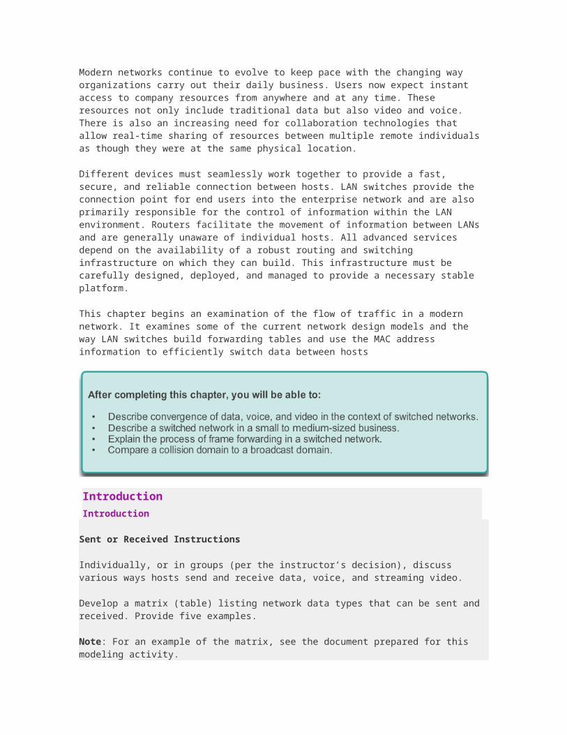
With the increasing demands of the converged network, the network must be developed with an architectural approach that embeds intelligence, simplifies operations, and is scalable to meet future demands. One of the more recent developments in network design is illustrated by the Cisco Borderless Network architecture illustrated in Figure 1.
The Cisco Borderless Network is a network architecture that combines several innovations and design considerations to allow organizations to connect anyone, anywhere, anytime, and on any device securely, reliably, and seamlessly. This architecture is designed to address IT and business challenges, such as supporting the converged network and changing work patterns.
The Cisco Borderless Network is built on an infrastructure of scalable and resilient hardware and software. It enables different elements, from access switches to wireless access points to work

together and allow users to access resources from any place at any time, providing optimization, scalability, and security to collaboration and virtualization.
In Figure 2, play the video to learn more about the evolution of the Cisco Borderless Network.
LAN Design
Converged Networks
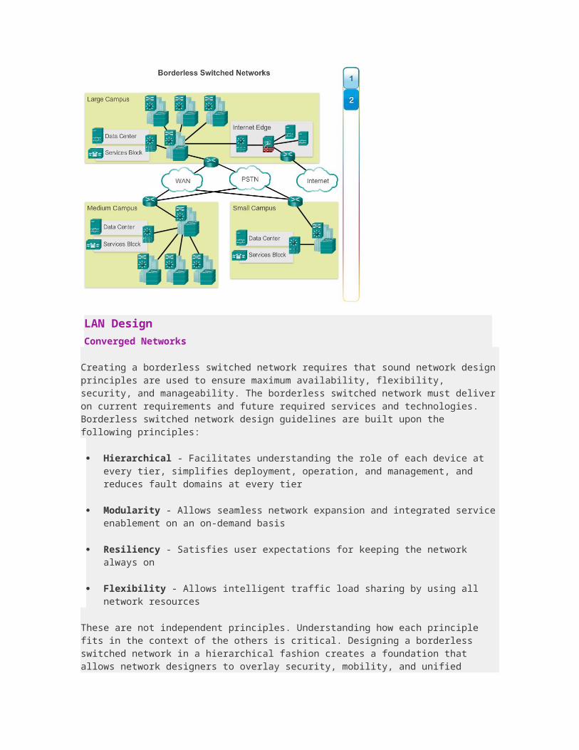
Creating a borderless switched network requires that sound network design principles are used to ensure maximum availability, flexibility, security, and manageability. The borderless switched network must deliver on current requirements and future required services and technologies. Borderless switched network design guidelines are built upon the following principles:
Hierarchical - Facilitates understanding the role of each device at every tier, simplifies deployment, operation, and management, and reduces fault domains at every tier
Modularity - Allows seamless network expansion and integrated service enablement on an on-demand basis
Resiliency - Satisfies user expectations for keeping the network always on
Flexibility - Allows intelligent traffic load sharing by using all network resources
These are not independent principles. Understanding how each principle fits in the context of the others is critical. Designing a borderless switched network in a hierarchical fashion creates a foundation that allows network designers to overlay security, mobility, and unified communication features. Two time-tested and proven hierarchical design frameworks for campus networks are the three-tier layer and the two-tier layer models, as illustrated in the figure.
The three critical layers within these tiered designs are the access, distribution, and core layers. Each layer can be seen as a well-defined, structured module with specific roles and functions in the campus network. Introducing modularity into the campus hierarchical design further ensures that the campus network remains resilient and flexible enough to provide critical network services. Modularity also helps to allow for growth and changes that occur over time.
LAN Design
Converged Networks
Access Layer
The access layer represents the network edge, where traffic enters or exits the campus network. Traditionally, the primary function of an access layer switch is to provide network access to the user. Access layer switches connect to distribution layer switches, which implement network foundation technologies such as routing, quality of service, and security.
To meet network application and end-user demand, the next-generation switching platforms now provide more converged, integrated, and intelligent services to various types of endpoints at the network edge. Building intelligence into access layer switches allows applications to operate on the network more efficiently and securely.
Distribution Layer
The distribution layer interfaces between the access layer and the core layer to provide many important functions, including:
Aggregating large-scale wiring closet networks
Aggregating Layer 2 broadcast domains and Layer 3 routing boundaries

Providing intelligent switching, routing, and network access policy functions to access the rest of the network
Providing high availability through redundant distribution layer switches to the end-user and equal cost paths to the core
Providing differentiated services to various classes of service applications at the edge of network
Core Layer
The core layer is the network backbone. It connects several layers of the campus network. The core layer serves as the aggregator for all of the other campus blocks and ties the campus together with the rest of the network. The primary purpose of the core layer is to provide fault isolation and high-speed backbone connectivity.
Figure 1 shows a three-tier campus network design for organizations where the access, distribution, and core are each separate layers. To build a simplified, scalable, cost-effective, and efficient physical cable layout design, the recommendation is to build an extended-star physical network topology from a centralized building location to all other buildings on the same campus.
In some cases, because of a lack of physical or network scalability restrictions, maintaining a separate distribution and core layer is not required. In smaller campus locations where there are fewer users accessing the network or in campus sites consisting of a single building, separate core and distribution layers may not be needed. In this scenario, the recommendation is the alternate two-tier campus network design, also known as the collapsed core network design.
Figure 2 shows a two-tier campus network design example for an enterprise campus where the distribution and core layers are collapsed into a single layer.

LAN Design
Switched Networks
The role of switched networks has evolved dramatically in the last two decades. It was not long ago that flat Layer 2 switched networks were the norm. Flat Layer 2 data networks relied on the basic properties of Ethernet and the widespread use of hub repeaters to propagate LAN traffic throughout an organization. As shown in Figure 1, networks have fundamentally changed to switched LANs in a hierarchical network. A switched LAN allows more flexibility, traffic management, and additional features, such as:
Quality of service
Additional security
Support for wireless networking and connectivity
Support for new technologies, such as IP telephony and mobility services
Figure 2 shows the hierarchical design used in the borderless switched network.

LAN Design
Switched Networks
There are various types of switches used in business networks. It is important to deploy the appropriate types of switches based on network requirements. Figure 1 highlights some common business considerations when selecting switch equipment.
When selecting the type of switch, the network designer must choose between a fixed or a modular configuration, and stackable or non-stackable. Another consideration is the thickness of the switch, which is expressed in number of rack units. This is important for switches that are mounted in a rack. For example, the fixed configuration switches shown in Figure 2 are all 1 rack unit (1U). These options are sometimes referred to as switch form factors.
Fixed Configuration Switches

Fixed configuration switches do not support features or options beyond those that originally came with the switch (Figure 2). The particular model determines the features and options available. For example, a 24-port gigabit fixed switch cannot support additional ports. There are typically different configuration choices that vary in how many and what types of ports are included with a fixed configuration switch.
Modular Configuration Switches
Modular configuration switches offer more flexibility in their configuration. Modular configuration switches typically come with different sized chassis that allow for the installation of different numbers of modular line cards (Figure 3). The line cards actually contain the ports. The line card fits into the switch chassis the way that expansion cards fit into a PC. The larger the chassis, the more modules it can support. There can be many different chassis sizes to choose from. A modular switch with a 24-port line card supports an additional 24 port line card, to bring the total number of ports up to 48.
Stackable Configuration Switches
Stackable configuration switches can be interconnected using a special cable that provides high-bandwidth throughput between the switches (Figure 4). Cisco StackWise technology allows the interconnection of up to nine switches. Switches can be stacked one on top of the other with cables connecting the switches in a daisy chain fashion. The stacked switches effectively operate as a single larger switch. Stackable switches are desirable where fault tolerance and bandwidth availability are critical and a modular switch is too costly to implement. Using cross-connected connections, the network can recover quickly if a single switch fails. Stackable switches use a special port for interconnections. Many Cisco stackable switches also support StackPower technology, which enables power sharing among stack members.


The Switched Environment
Frame Forwarding
The concept of switching and forwarding frames is universal in networking and telecommunications. Various types of switches are used in LANs, WANs, and the public switched telephone network (PSTN). The fundamental concept of switching refers to a device making a decision based on two criteria:
Ingress port
Destination address
The decision on how a switch forwards traffic is made in relation to the flow of that traffic. The term ingress is used to describe where a frame enters the device on a port. The term egress is used to describe frames leaving the device from a particular port.

When a switch makes a decision, it is based on the ingress port and the destination address of the message.
A LAN switch maintains a table that it uses to determine how to forward traffic through the switch. Click the Play button in the figure to see an animation of the switching process. In this example:
If a message enters switch port 1 and has a destination address of EA, then the switch forwards the traffic out port 4.
If a message enters switch port 5 and has a destination address of EE, then the switch forwards the traffic out port 1.
If a message enters switch port 3 and has a destination address of AB, then the switch forwards the traffic out port 6.
The only intelligence of the LAN switch is its ability to use its table to forward traffic based on the ingress port and the destination address of a message. With a LAN switch, there is only one master switching table that describes a strict association between addresses and ports; therefore, a message with a given destination address always exits the same egress port, regardless of the ingress port it enters.
Cisco LAN switches forward Ethernet frames based on the destination MAC address of the frames.
The Switched Environment
Frame Forwarding
Switches use MAC addresses to direct network communications through the switch to the appropriate port toward the destination. A switch is made up of integrated circuits and the accompanying software that controls the data paths through the switch. For a switch to know which port to use to transmit a frame, it must first learn which devices exist on each port. As the switch learns the relationship of ports to devices, it builds a table called a MAC address, or content addressable memory (CAM) table. CAM is a special type of memory used in high-speed searching applications.
LAN switches determine how to handle incoming data frames by maintaining the MAC address table. A switch builds its MAC address table by recording the MAC address of each device

connected to each of its ports. The switch uses the information in the MAC address table to send frames destined for a specific device out the port which has been assigned to that device.
A switch populates the MAC address table based on source MAC addresses. When a switch receives an incoming frame with a destination MAC address that is not found in the MAC address table, the switch forwards the frame out of all ports (flooding) except for the ingress port of the frame. When the destination device responds, the switch adds the source MAC address of the frame and the port where the frame was received to the MAC address table. In networks with multiple interconnected switches, the MAC address table contains multiple MAC addresses for a single port connected to the other switches.
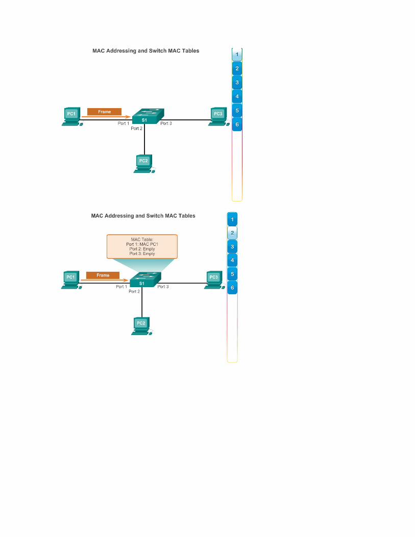
The following steps describe the process of building the MAC address table:
1. The switch receives a frame from PC 1 on Port 1 (Figure 1).
2. The switch examines the source MAC address and compares it to MAC address table.
If the address is not in the MAC address table, it associates the source MAC address of PC 1 with the ingress port (Port 1) in the MAC address table (Figure 2).
If the MAC address table already has an entry for that source address, it resets the aging timer. An entry for a MAC address is typically kept for five minutes.
3. After the switch has recorded the source address information, the switch examines the destination MAC address.
If the destination address is not in the MAC table or if it’s a broadcast MAC address, as indicated by all Fs, the switch floods the frame to all ports, except the ingress port (Figure 3).
4. The destination device (PC 3) replies to the frame with a unicast frame addressed to PC 1 (Figure 4).
5. The switch enters the source MAC address of PC 3 and the port number of the ingress port into the address table. The destination address of the frame and its associated egress port is found in the MAC address table (Figure 5).
6. The switch can now forward frames between these source and destination devices without flooding, because it has entries in the address table that identify the associated ports (Figure 6).


The Switched Environment
Frame Forwarding
As networks grew and enterprises began to experience slower network performance, Ethernet bridges (an early version of a switch) were added to networks to limit the size of the collision domains. In the 1990s, advancements in integrated circuit technologies allowed for LAN switches to replace Ethernet bridges. These LAN switches were able to move the Layer 2 forwarding decisions from software to application-specific-integrated circuits (ASICs). ASICs reduce the packet-handling time within the device, and allow the device to handle an increased number of ports without degrading performance. This method of forwarding data frames at Layer 2 was referred to as store-and-forward switching. This term distinguished it from cut-through switching.

As shown in Figure 1, the store-and-forward method makes a forwarding decision on a frame after it has received the entire frame and then checked the frame for errors.
By contrast, the cut-through method, as shown in Figure 2 begins the forwarding process after the destination MAC address of an incoming frame and the egress port has been determined.
The Switched Environment
Frame Forwarding
Store-and-forward switching has two primary characteristics that distinguish it from cut-through: error checking and automatic buffering.

Error Checking
A switch using store-and-forward switching performs an error check on an incoming frame. After receiving the entire frame on the ingress port, as shown in the figure, the switch compares the frame-check-sequence (FCS) value in the last field of the datagram against its own FCS calculations. The FCS is an error checking process that helps to ensure that the frame is free of physical and data-link errors. If the frame is error-free, the switch forwards the frame. Otherwise the frame is dropped.
Automatic Buffering
The ingress port buffering process used by store-and-forward switches provides the flexibility to support any mix of Ethernet speeds. For example, handling an incoming frame traveling into a 100 Mb/s Ethernet port that must be sent out a 1 Gb/s interface would require using the store-and-forward method. With any mismatch in speeds between the ingress and egress ports, the switch stores the entire frame in a buffer, computes the FCS check, forwards it to the egress port buffer and then sends it.
Store-and-forward switching is Cisco’s primary LAN switching method.
A store-and-forward switch drops frames that do not pass the FCS check, therefore does not forward invalid frames. By contrast, a cut-through switch may forward invalid frames because no FCS check is performed.
The Switched Environment
Frame Forwarding
An advantage to cut-through switching is the ability of the switch to start forwarding a frame earlier than store-and-forward switching. There are two primary characteristics of cut-through switching: rapid frame forwarding and fragment free.
Rapid Frame Forwarding

As indicated in the figure, a switch using the cut-through method can make a forwarding decision as soon as it has looked up the destination MAC address of the frame in its MAC address table. The switch does not have to wait for the rest of the frame to enter the ingress port before making its forwarding decision.
With today’s MAC controllers and ASICs, a switch using the cut-through method can quickly decide whether it needs to examine a larger portion of a frame’s headers for additional filtering purposes. For example, the switch can analyze past the first 14 bytes (the source MAC address, destination MAC, and the EtherType fields), and examine an additional 40 bytes in order to perform more sophisticated functions relative to IPv4 Layers 3 and 4.
The cut-through switching method does not drop most invalid frames. Frames with errors are forwarded to other segments of the network. If there is a high error rate (invalid frames) in the network, cut-through switching can have a negative impact on bandwidth; thus, clogging up bandwidth with damaged and invalid frames.
Fragment Free
Fragment free switching is a modified form of cut-through switching in which the switch waits for the collision window (64 bytes) to pass before forwarding the frame. This means each frame will be checked into the data field to make sure no fragmentation has occurred. Fragment free mode provides better error checking than cut-through, with practically no increase in latency.
The lower latency speed of cut-through switching makes it more appropriate for extremely demanding, high-performance computing (HPC) applications that require process-to-process latencies of 10 microseconds or less.
The Switched Environment
Switching Domains

In hub-based Ethernet segments, network devices compete for the medium, because devices must take turns when transmitting. The network segments that share the same bandwidth between devices are known as collision domains, because when two or more devices within that segment try to communicate at the same time, collisions may occur.
It is possible, however, to use other network devices (examples would include switches and routers) operating at the TCP/IP model network access layer and above to divide a network into segments and reduce the number of devices that compete for bandwidth. Each new segment results in a new collision domain. More bandwidth is available to the devices on a segment, and collisions in one collision domain do not interfere with the other segments. This is also known as microsegmentation.
As shown in the figure, each switch port connects to a single PC or server, and each switch port represents a separate collision domain.
The Switched Environment
Switching Domains
Although switches filter most frames based on MAC addresses, they do not filter broadcast frames. For other switches on the LAN to receive broadcast frames, switches must flood these frames out all ports. A collection of interconnected switches forms a single broadcast domain. Only a network layer device, such as a router, can divide a Layer 2 broadcast domain. Routers are used to segment both collision and broadcast domains.
When a device sends a Layer 2 broadcast, the destination MAC address in the frame is set to all binary ones. A frame with a destination MAC address of all binary ones is received by all devices in the broadcast domain.
The Layer 2 broadcast domain is referred to as the MAC broadcast domain. The MAC broadcast domain consists of all devices on the LAN that receive broadcast frames from a host.

Click Play in the figure to see this in the first half of the animation.
When a switch receives a broadcast frame, it forwards the frame out each of its ports, except the ingress port where the broadcast frame was received. Each device connected to the switch receives a copy of the broadcast frame and processes it. Broadcasts are sometimes necessary for initially locating other devices and network services, but they also reduce network efficiency. Network bandwidth is used to propagate the broadcast traffic. Too many broadcasts and a heavy traffic load on a network can result in congestion: a slow-down in the network performance.
When two switches are connected together, the broadcast domain is increased, as seen in the second half of the animation. In this case, a broadcast frame is forwarded to all connected ports on switch S1. Switch S1 is connected to switch S2. The frame is then also propagated to all devices connected to switch S2.
The Switched Environment
Switching Domains
LAN switches have special characteristics that make them effective at alleviating network congestion. First, they allow the segmentation of a LAN into separate collision domains. Each port of the switch represents a separate collision domain and provides the full bandwidth to the device or devices that are connected to that port. Second, they provide full-duplex communication between devices. A full-duplex connection can carry transmitted and received signals at the same time. Full-duplex connections have dramatically increased LAN network performance, and are required for 1 Gb/s Ethernet speeds and higher.
Switches interconnect LAN segments (collision domains), use a table of MAC addresses to determine the segment to which the frame is to be sent, and can lessen or eliminate collisions entirely. Following are some important characteristics of switches that contribute to alleviating network congestion:
High port density - Switches have high-port densities: 24- and 48-port switches are often just 1 rack unit (1.75 inches) in height and operate at speeds of 100 Mb/s, 1 Gb/s, and 10 Gb/s. Large enterprise switches may support many hundreds of ports.
Large frame buffers - The ability to store more received frames before having to start dropping them is useful, particularly when there may be congested ports to servers or other parts of the network.
Port speed - Depending on the cost of a switch, it may be possible to support a mixture of speeds. Ports of 100 Mb/s, and 1 or 10 Gb/s are common (100 Gb/s is also possible).
Fast internal switching - Having fast internal forwarding capabilities allows high performance. The method that is used may be a fast internal bus or shared memory, which affects the overall performance of the switch.
Low per-port cost - Switches provide high-port density at a lower cost. For this reason, LAN switches can accommodate network designs featuring fewer users per segment, therefore, increasing the average available bandwidth per user.

Summary
Summary
It’s Network Access Time
Use Packet Tracer for this activity. Internet connectivity is not required in this design. Work with a classmate to create two network designs to accommodate the following scenarios:
Scenario 1 – Classroom Design (LAN)
15 student end devices represented by 1 or 2 PCs
1 instructor end device preferably represented by a server
Stream video presentations over LAN connection
Scenario 2 – Administrative Design (WAN)
All requirements as listed in Scenario 1
Access to and from a remote administrative server for video presentations and pushed updates for network application software
Both the LAN and WAN designs should fit on to one Packet Tracer file screen. All intermediary devices should be labeled with the switch model (or name) and the router model (or name).

Save your work and be ready to justify your device decisions and layout to your instructor and the class.
Class Activity - It's Network Access Time Instructions
Summary
Summary
As a recently hired LAN technician, your network manager has asked you to demonstrate your ability to configure a small LAN. Your tasks include configuring initial settings on two switches using the Cisco IOS and configuring IP address parameters on host devices to provide end-to-end connectivity. You are to use two switches and two hosts/PCs on a cabled and powered network.
Packet Tracer - Skills Integration Challenge Instructions
Packet Tracer - Skills Integration Challenge PKA
Summary
Summary
We have seen that the trend in networks is towards convergence using a single set of wires and devices to handle voice, video, and data transmission. In addition, there has been a dramatic shift in the way businesses operate. No longer are employees constrained to physical offices or by geographic boundaries. Resources must now be seamlessly available anytime and anywhere. The Cisco Borderless Network architecture enables different elements, from access switches to wireless access points, to work together and allow users to access resources from any place at any time.
The traditional three-layer hierarchical design model divides the network into core, distribution, and access layers, and allows each portion of the network to be optimized for specific functionality. It provides modularity, resiliency, and flexibility, which provides a foundation that allows network designers to overlay security, mobility, and unified communication features. In some networks, having a separate core and distribution layer is not required. In these networks, the functionality of the core layer and the distribution layer are often collapsed together.
Cisco LAN switches use ASICs to forward frames based on the destination MAC address. Before this can be accomplished, it must first use the source MAC address of incoming frames to build up a MAC address table in content-addressable memory (CAM). If the destination MAC address is contained in this table, the frame is forwarded only to the specific destination port. In cases were the destination MAC address is not found in the MAC address table, the frames are flooded out all ports, except the one on which the frame was received.
Switches use either store-and-forward or cut-through switching. Store-and-forward reads the entire frame into a buffer and checks the CRC before forwarding the frame. Cut-through switching only reads the first portion of the frame and starts forwarding it as soon as the destination address is read. Although this is extremely fast, no error checking is done on the frame before forwarding.

Every port on a switch forms a separate collision domain allowing for extremely high-speed full-duplex communication. Switch ports do not block broadcasts and connecting switches together can extend the size of the broadcast domain often resulting in degraded network performance.