canvas how-to: technical...
TRANSCRIPT
Text
Effec
tsCorp
ora
teFl
ow
Illu
stra
tion
Imag
eEditin
gAuto
mat
ion
Web
DenebaCreative Department
Copyright © 1995-2002Deneba Systems Inc.
All Right Reserved Worldwide
CanvasTipsand
Techniques
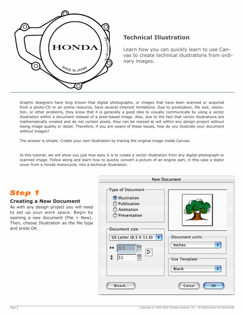
Technical Illustration
Learn how you can quickly learn to use Can-vas to create technical illustrations from ordi-nary images.
Graphic designers have long known that digital photographs, or images that have been scanned or acquiredfrom a photo-CD or an online resource, have several inherent limitations. Due to pixelization, file size, resolu-tion, or other problems, they know that it is generally a good idea to visually communicate by using a vectorillustration within a document instead of a pixel-based image. Also, due to the fact that vector illustrations aremathematically created and do not contain pixels, they can be resized at will within any design project withoutlosing image quality or detail. Therefore, if you are aware of these issues, how do you illustrate your documentwithout images?
The answer is simple. Create your own illustration by tracing the original image inside Canvas.
In this tutorial, we will show you just how easy it is to create a vector illustration from any digital photograph orscanned image. Follow along and learn how to quickly convert a picture of an engine part, in this case a statorcover from a Honda motorcycle, into a technical illustration.
Page 2 Copyright © 1995-2002 Deneba Systems, Inc. All Rights Reserved Worldwide
Creating a New DocumentAs with any design project you will needto set up your work space. Begin byopening a new document (File > New).Then, choose Illustration as the file typeand press OK.
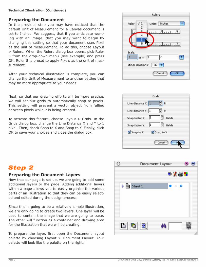
Preparing the DocumentIn the previous step you may have noticed that thedefault Unit of Measurement for a Canvas document isset to Inches. We suggest, that if you anticipate work-ing with an image, that you may want to begin bychanging this setting so that your document uses Pixelas the unit of measurement. To do this, choose Layout> Rulers. When the Rulers dialog box opens, pick Ruler5 from the drop-down menu (see example) and pressOK. Ruler 5 is preset to apply Pixels as the unit of mea-surement.
After your technical illustration is complete, you canchange the Unit of Measurement to another setting thatmay be more appropriate to your needs.
Next, so that our drawing efforts will be more precise,we will set our grids to automatically snap to pixels.This setting will prevent a vector object from fallingbetween pixels while it is being created.
To activate this feature, choose Layout > Grids. In theGrids dialog box, change the Line Distance X and Y to 1pixel. Then, check Snap to X and Snap to Y. Finally, clickOK to save your choices and close the dialog box.
Page 3 Copyright © 1995-2002 Deneba Systems, Inc. All Rights Reserved Worldwide
Preparing the Document LayersNow that our page is set up, we are going to add someadditional layers to the page. Adding additional layerswithin a page allows you to easily organize the variousparts of an illustration so that they can be easily select-ed and edited during the design process.
Since this is going to be a relatively simple illustration,we are only going to create two layers. One layer will beused to contain the image that we are going to trace.The other will function as a container and drawing areafor the illustration that we will be creating.
To prepare the layer, first open the Document layoutpalette by choosing Layout > Document Layout. Yourpalette will look like the palette on the right.
Technical Illustration (Continued)

Next select the “+” sign (Windows) or the arrow (MacOS) next to Sheet 1 to expand the view and reveal thelayers inside. At this point, you should only have onelayer named Layer #1 inside.
Page 4 Copyright © 1995-2002 Deneba Systems, Inc. All Rights Reserved Worldwide
To create the second layer that your project will need,simply click once on the New Layer icon. Doing so willautomatically create your new layer, which will begiven the default name of “Layer #2.”
Select Layer #1 within the Document Layout paletteand double-click.
Technical Illustration (Continued)
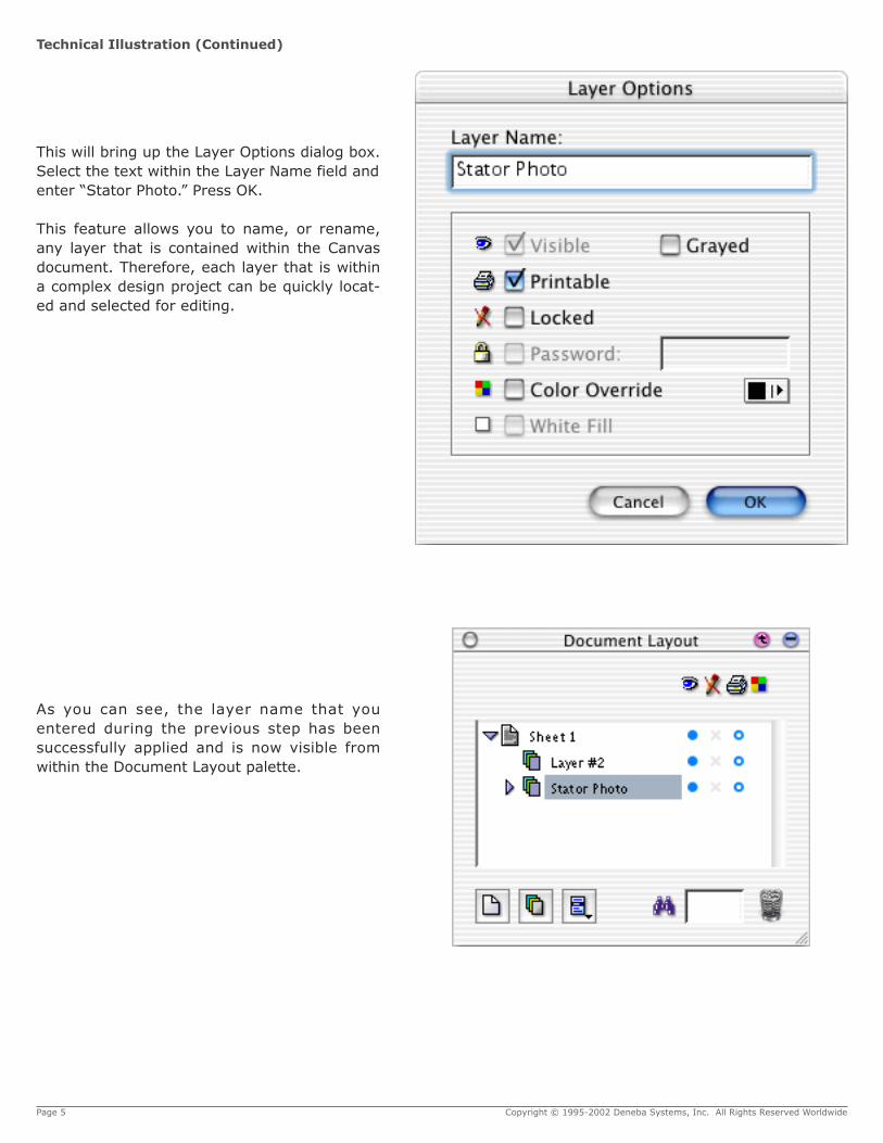
This will bring up the Layer Options dialog box.Select the text within the Layer Name field andenter “Stator Photo.” Press OK.
This feature allows you to name, or rename,any layer that is contained within the Canvasdocument. Therefore, each layer that is withina complex design project can be quickly locat-ed and selected for editing.
Page 5 Copyright © 1995-2002 Deneba Systems, Inc. All Rights Reserved Worldwide
As you can see, the layer name that youentered during the previous step has beensuccessfully applied and is now visible fromwithin the Document Layout palette.
Technical Illustration (Continued)

Page 6 Copyright © 1995-2002 Deneba Systems, Inc. All Rights Reserved Worldwide
Repeat the same steps to rename Layer #2.Only this time enter Stator Illustration as thislayer will contain the vector illustration that wewill be creating. When you‘re finished, pressOK.
Notice that both names appear within the Doc-ument Layout palette.
At this point, if you are unfamiliar with thispalette, you might want to experiment withsome of the other controls. If you have otherquestions, you might want to review the Can-vas User‘s Guide for further information.
Technical Illustration (Continued)
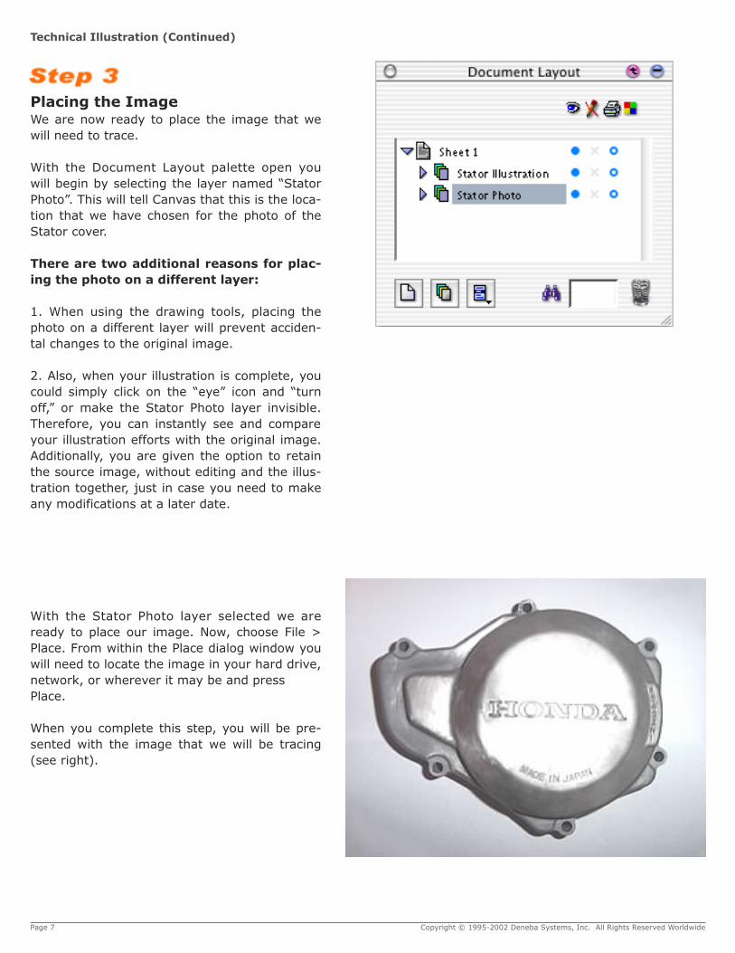
Placing the ImageWe are now ready to place the image that wewill need to trace.
With the Document Layout palette open youwill begin by selecting the layer named “StatorPhoto”. This will tell Canvas that this is the loca-tion that we have chosen for the photo of theStator cover.
There are two additional reasons for plac-ing the photo on a different layer:
1. When using the drawing tools, placing thephoto on a different layer will prevent acciden-tal changes to the original image.
2. Also, when your illustration is complete, youcould simply click on the “eye” icon and “turnoff,” or make the Stator Photo layer invisible.Therefore, you can instantly see and compareyour illustration efforts with the original image.Additionally, you are given the option to retainthe source image, without editing and the illus-tration together, just in case you need to makeany modifications at a later date.
With the Stator Photo layer selected we areready to place our image. Now, choose File >Place. From within the Place dialog window youwill need to locate the image in your hard drive,network, or wherever it may be and pressPlace.
When you complete this step, you will be pre-sented with the image that we will be tracing(see right).
Page 7 Copyright © 1995-2002 Deneba Systems, Inc. All Rights Reserved Worldwide
Technical Illustration (Continued)
Page 8 Copyright © 1995-2002 Deneba Systems, Inc. All Rights Reserved Worldwide
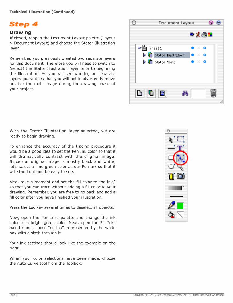
DrawingIf closed, reopen the Document Layout palette (Layout> Document Layout) and choose the Stator Illustrationlayer.
Remember, you previously created two separate layersfor this document. Therefore you will need to switch to(select) the Stator Illustration layer prior to beginningthe illustration. As you will see working on separatelayers guarantees that you will not inadvertently moveor alter the main image during the drawing phase ofyour project.
With the Stator Illustration layer selected, we areready to begin drawing.
To enhance the accuracy of the tracing procedure itwould be a good idea to set the Pen Ink color so that itwill dramatically contrast with the original image.Since our original image is mostly black and white,let‘s select a lime green color as our Pen Ink so that itwill stand out and be easy to see.
Also, take a moment and set the fill color to “no ink,”so that you can trace without adding a fill color to yourdrawing. Remember, you are free to go back and add afill color after you have finished your illustration.
Press the Esc key several times to deselect all objects.
Now, open the Pen Inks palette and change the inkcolor to a bright green color. Next, open the Fill Inkspalette and choose “no ink”, represented by the whitebox with a slash through it.
Your ink settings should look like the example on theright.
When your color selections have been made, choosethe Auto Curve tool from the Toolbox.
Technical Illustration (Continued)
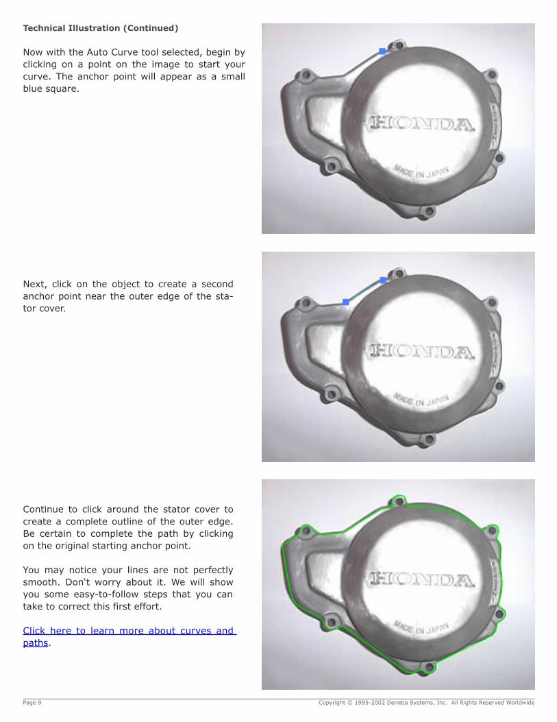
Next, click on the object to create a secondanchor point near the outer edge of the sta-tor cover.
Page 9 Copyright © 1995-2002 Deneba Systems, Inc. All Rights Reserved Worldwide
Continue to click around the stator cover tocreate a complete outline of the outer edge.Be certain to complete the path by clickingon the original starting anchor point.
You may notice your lines are not perfectlysmooth. Don‘t worry about it. We will showyou some easy-to-follow steps that you cantake to correct this first effort.
Click here to learn more about curves andpaths.
Now with the Auto Curve tool selected, begin byclicking on a point on the image to start yourcurve. The anchor point will appear as a smallblue square.
Technical Illustration (Continued)
Page 10 Copyright © 1995-2002 Deneba Systems, Inc. All Rights Reserved Worldwide
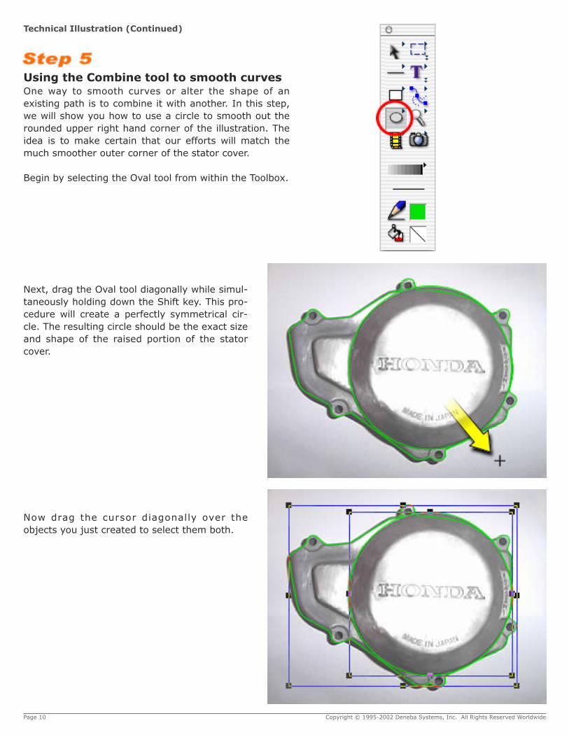
Using the Combine tool to smooth curvesOne way to smooth curves or alter the shape of anexisting path is to combine it with another. In this step,we will show you how to use a circle to smooth out therounded upper right hand corner of the illustration. Theidea is to make certain that our efforts will match themuch smoother outer corner of the stator cover.
Begin by selecting the Oval tool from within the Toolbox.
Next, drag the Oval tool diagonally while simul-taneously holding down the Shift key. This pro-cedure will create a perfectly symmetrical cir-cle. The resulting circle should be the exact sizeand shape of the raised portion of the statorcover.
Now drag the cursor diagonally over theobjects you just created to select them both.
Technical Illustration (Continued)
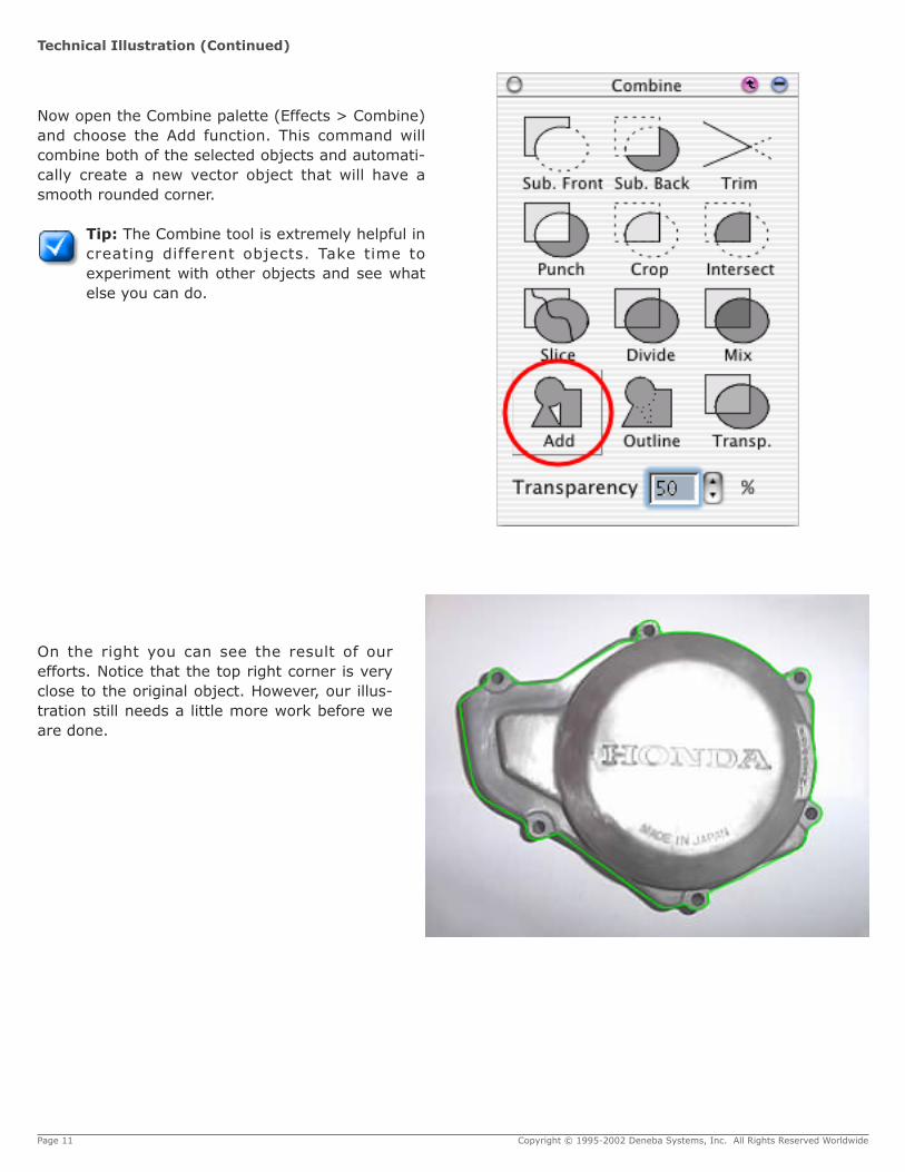
Now open the Combine palette (Effects > Combine)and choose the Add function. This command willcombine both of the selected objects and automati-cally create a new vector object that will have asmooth rounded corner.
Tip: The Combine tool is extremely helpful increating different objects. Take time toexperiment with other objects and see whatelse you can do.
Page 11 Copyright © 1995-2002 Deneba Systems, Inc. All Rights Reserved Worldwide
On the right you can see the result of ourefforts. Notice that the top right corner is veryclose to the original object. However, our illus-tration still needs a little more work before weare done.
Technical Illustration (Continued)

Using the Handle and Tangent LinesUsing the handles and tangent lines is another optionthat you can use to edit vector curves within Canvas.
However, at this point it might be a good idea to do alittle review before we proceed. Let‘s take a minute tofamiliarize ourselves with some basic vector drawingterms.
Anchor Points: The Anchor Point determines where apath begins and ends. During the vector editing pro-cess they will appear as small blue squares. However,they automatically turn into empty blue square outlineswhen they are selected for use.
Tangent Lines: Tangent Lines provide a visual refer-ence during the editing process. They allow you to viewhow the shape of curved segments are affected or con-trolled during editing. Also note that a Tangent Line willaffect the adjacent segment.
Handles: A Handle is the control point that you use tomove and therefore edit the Tangent Line.
Now lets take a close look at our previous work.Zoom into a section so that you can view a close-upof a section of the work area. Set the viewing sothat it appears similar to the example on the right.Next, double-click on the path to place the objectinto vector-edit mode.
When you are in edit-mode, the anchor points willappear as small blue squares. The handles (controlpoints) will appear as small blue circles. Rememberthat clicking on an anchor point will reveal the tan-gent line of the selected anchor point and those ofits neighbors. Use the pointer and select the handlesto reshape the path so that it matches the contourof the stator cover. If this is your first vector editingproject, you might want to take a few minutes andexperiment with this procedure.
Tip:To edit a path, it is advisable to first zoomin to the object to get a better view.
Click here to learn more about handles and tangentlines.
Page 12 Copyright © 1995-2002 Deneba Systems, Inc. All Rights Reserved Worldwide
Technical Illustration (Continued)

Page 13 Copyright © 1995-2002 Deneba Systems, Inc. All Rights Reserved Worldwide
Let‘s finish up this step and go back to theOval tool and recreate the raised sections ofthe stator cover.
First select the Oval tool from the Toolbox.
Adding TextNotice the “Made In Japan” and “Honda” let-tering on the cover? Let us show you howeasy it is to recreate this text and place it on apath within Canvas.
Now that our cover outline completed, we areready to add the needed text. Begin by firstselecting the Text tool from the Toolbox.
Technical Illustration (Continued)
Then using the same techniques we used instep five, create two circles and place them onthe stator cover (see example).
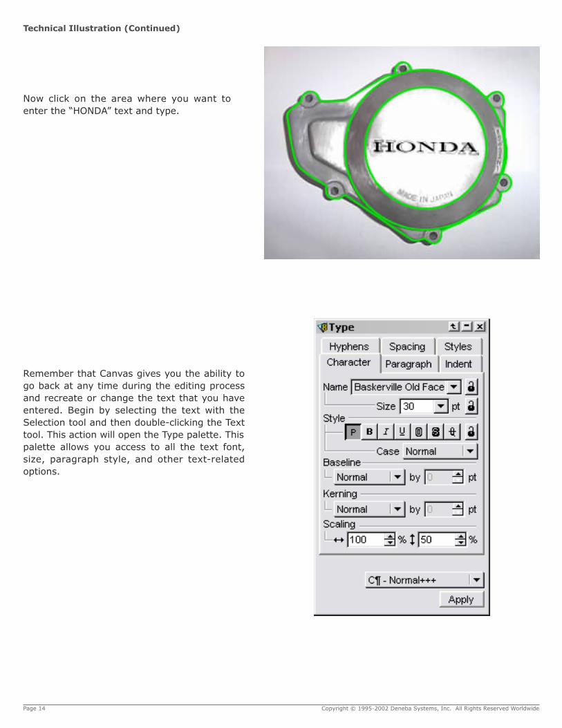
Remember that Canvas gives you the ability togo back at any time during the editing processand recreate or change the text that you haveentered. Begin by selecting the text with theSelection tool and then double-clicking the Texttool. This action will open the Type palette. Thispalette allows you access to all the text font,size, paragraph style, and other text-relatedoptions.
Page 14 Copyright © 1995-2002 Deneba Systems, Inc. All Rights Reserved Worldwide
Technical Illustration (Continued)
Now click on the area where you want toenter the “HONDA” text and type.
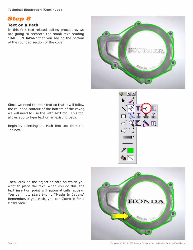
Since we need to enter text so that it will followthe rounded contour of the bottom of the cover,we will need to use the Path Text tool. This toolallows you to type text on an existing path.
Begin by selecting the Path Text tool from theToolbox.
Page 15 Copyright © 1995-2002 Deneba Systems, Inc. All Rights Reserved Worldwide
Then, click on the object or path on which youwant to place the text. When you do this, thetext insertion point will automatically appear.You can now start typing “Made In Japan.”Remember, if you wish, you can Zoom in for acloser view.
Technical Illustration (Continued)
Text on a PathIn this first text-related editing procedure, weare going to recreate the small text reading“MADE IN JAPAN” that you see on the bottomof the rounded section of the cover.
Page 16 Copyright © 1995-2002 Deneba Systems, Inc. All Rights Reserved Worldwide
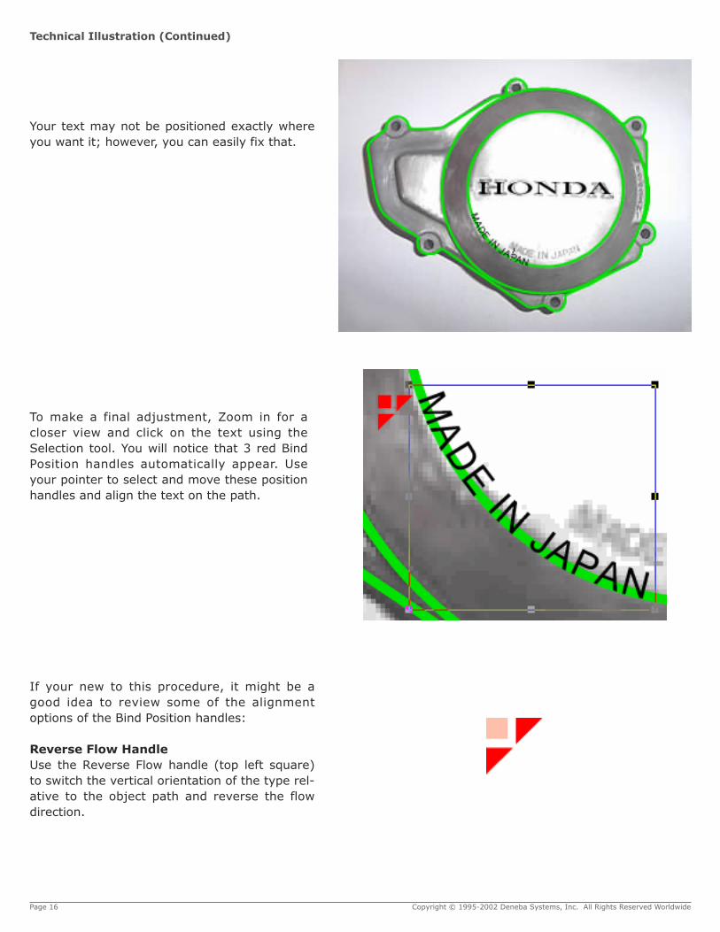
To make a final adjustment, Zoom in for acloser view and click on the text using theSelection tool. You will notice that 3 red BindPosition handles automatically appear. Useyour pointer to select and move these positionhandles and align the text on the path.
Technical Illustration (Continued)
Your text may not be positioned exactly whereyou want it; however, you can easily fix that.
If your new to this procedure, it might be agood idea to review some of the alignmentoptions of the Bind Position handles:
Reverse Flow HandleUse the Reverse Flow handle (top left square)to switch the vertical orientation of the type rel-ative to the object path and reverse the flowdirection.

The Bind Position handles give you the abilityto place the text with professional precisionand accuracy.
Adding the Final TouchesBy using some of the previous steps that we cov-ered earlier in this tutorial we are going to showyou how to finish our project.
In this next step, we will add the smaller holes forthat are used to hold the bolts for the cover. We willalso demonstrate how to add the other less notice-able items.
First, select the Oval Tool so that we can create thebolt holes that you see on the cover.
Page 17 Copyright © 1995-2002 Deneba Systems, Inc. All Rights Reserved Worldwide
Technical Illustration (Continued)
Alignment HandleThe Alignment handle (far right triangle) is used todrag and adjust the text to a specific point alongthe path.
Baseline Shift HandleUse the Baseline Shift (bottom triangle) handle tochange the elevation of the baseline relative to thepath. It works in both directions so you could pushthe text away from the oval or pull it toward thecenter.
Tip: Baseline is defined as the line on whichmost characters sit.
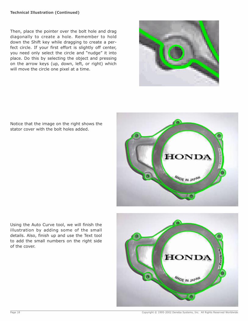
Notice that the image on the right shows thestator cover with the bolt holes added.
Using the Auto Curve tool, we will finish theillustration by adding some of the smalldetails. Also, finish up and use the Text toolto add the small numbers on the right sideof the cover.
Page 18 Copyright © 1995-2002 Deneba Systems, Inc. All Rights Reserved Worldwide
Technical Illustration (Continued)
Then, place the pointer over the bolt hole and dragdiagonally to create a hole. Remember to holddown the Shift key while dragging to create a per-fect circle. If your first effort is slightly off center,you need only select the circle and “nudge” it intoplace. Do this by selecting the object and pressingon the arrow keys (up, down, left, or right) whichwill move the circle one pixel at a time.
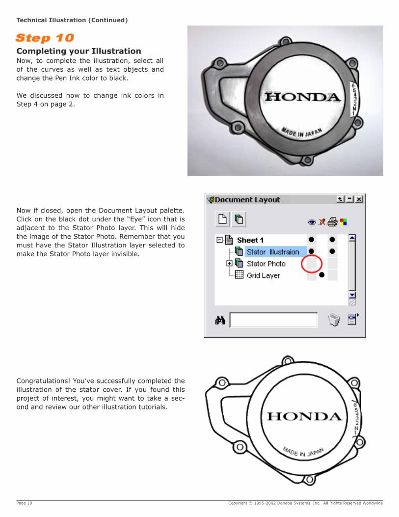
Now if closed, open the Document Layout palette.Click on the black dot under the “Eye” icon that isadjacent to the Stator Photo layer. This will hidethe image of the Stator Photo. Remember that youmust have the Stator Illustration layer selected tomake the Stator Photo layer invisible.
Congratulations! You‘ve successfully completed theillustration of the stator cover. If you found thisproject of interest, you might want to take a sec-ond and review our other illustration tutorials.
Page 19 Copyright © 1995-2002 Deneba Systems, Inc. All Rights Reserved Worldwide
Technical Illustration (Continued)
Completing your IllustrationNow, to complete the illustration, select allof the curves as well as text objects andchange the Pen Ink color to black.
We discussed how to change ink colors inStep 4 on page 2.