canopen quickstart guide - esd electronics, inc. - can ... led on: can bus-off 3.7 auto-starting...
TRANSCRIPT

CANopen Quickstart Guidefor the
Renesas CAN Development Kit RCDK8C
CANopen Quick Start Guide, rev. 1.00 1

1 Introduction
1.1 About CANopenCANopen is a higher layer protocol that runs on a CAN network. The CAN specification defines only the physical and data link layers in the ISO/OSI 7-layer Reference Model. This means that only the physical bus and the CAN message format is defined, but not how the CAN messages should be used. CANopen provides an open and standardized but customizable description of how to transfer data of different types between different CAN nodes, how accessible data (process data, configuration data etc.) is structured inside the node and what access methods to that data exist. This allows off-the-shelf CANopen compliant nodes to be purchased and plugged into a network with a minimum of effort. It also can be used in place of an in-house proprietary higher-layer-protocol development.
The development of CANopen is supervised by the CAN in Automation User's Group (CiA) and has being turned into an international standard. Use of CANopen does not require the payment of any royalties and the specification may be expanded or altered to suit if closed networks are being developed.
Typical applications for CANopen include:
● Commercial Vehicles● Medical Equipment● Maritime Electronics● Building Automation● Light Rail Systems
1.2 CANopen DemoThis add-on to the Renesas CAN Development Kit RCDK8C demonstrates the availability of two CANopen protocol stacks, MicroCANopen Plus and MicroCANopen Classic, for the Renesas R8C23 series.
2 Setup and ConnectionsTo set up the CANopen demos, follow the CAN Development Quick Start Guide chapter 2. The physical set-up used for the CANopen demo is exactly the same.
2.1 CAN Bit RateAll CANopen examples in this demo are using 500 kbaud, the same setting as the standard-CAN examples.
CANopen Quick Start Guide, rev. 1.00 2

3 CANopen Demo Description
3.1 Node IDIn CANopen, every node has a unique node ID between 1 and 127. For this demo, the node IDs 3 and 4 are used and there are programming files for both. The two boards must always be programmed with different node IDs!
3.2 PDOsThe RSK board's Renesas MCU acts as a CANopen Slave that produces and consumes process data which is transmitted via so-called Process Data Objects (PDOs) across the CAN network. Two Transmit Process Data Objects (TPDOs) are preconfigured and contain the state of the three push buttons (TPDO1, switch 1-3) and the current reading of the Analog-to-Digital Converter that is connected to the potentiometer (TPDO2). At the same time, two Receive Process Data Objects (RPDOs) are configured that contain data for on-board outputs: RPDO1 is linked to two LEDs (LED1 and LED2) while RPDO2 has an analog output value that is displayed in the LCD as a decimal value.
CAN-ID DATA1 DATA2 DATA3 DATA4
TPDO1 180h+Node ID Switches Heartbeat
Status 0 0
TPDO2 280h+Node ID Potentiometer (ADC) 0 0
RPDO1 200h+Node ID LEDs unused unused unused
RPDO2 300h+Node ID “Analog Out” (LCD) unused unused
Illustration 1: Predefined PDOs
From the eight bytes that each CAN message can hold, the PDOs in this example only use four. TPDO1 is sent periodically every 250 ms (Event Timer) and whenever there is a change-of-state. TPDO2 is sent periodically every 500 ms and whenever there is a change-of-state, but never more often than every 20 ms (Inhibit Time).
3.3 Heartbeats/Bootup and Heartbeat MonitoringEvery node sends out a periodic heartbeat message with the CAN identifier 700h+Node ID and one
CANopen Quick Start Guide, rev. 1.00 3
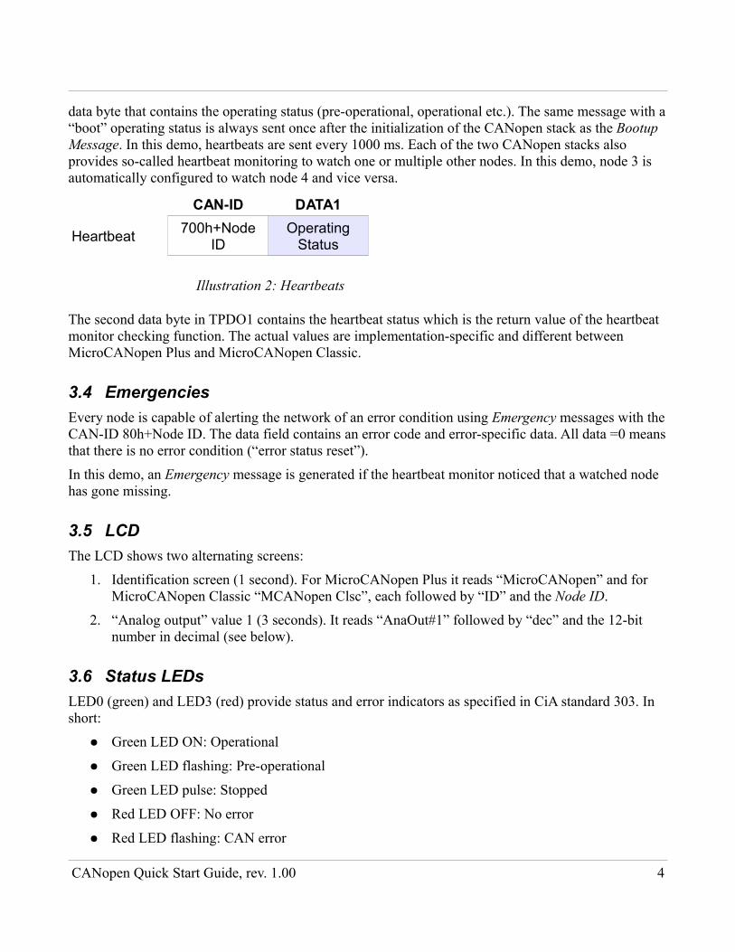
data byte that contains the operating status (pre-operational, operational etc.). The same message with a “boot” operating status is always sent once after the initialization of the CANopen stack as the Bootup Message. In this demo, heartbeats are sent every 1000 ms. Each of the two CANopen stacks also provides so-called heartbeat monitoring to watch one or multiple other nodes. In this demo, node 3 is automatically configured to watch node 4 and vice versa.
CAN-ID DATA1
Heartbeat 700h+Node ID
Operating Status
Illustration 2: Heartbeats
The second data byte in TPDO1 contains the heartbeat status which is the return value of the heartbeat monitor checking function. The actual values are implementation-specific and different between MicroCANopen Plus and MicroCANopen Classic.
3.4 EmergenciesEvery node is capable of alerting the network of an error condition using Emergency messages with the CAN-ID 80h+Node ID. The data field contains an error code and error-specific data. All data =0 means that there is no error condition (“error status reset”).
In this demo, an Emergency message is generated if the heartbeat monitor noticed that a watched node has gone missing.
3.5 LCDThe LCD shows two alternating screens:
1. Identification screen (1 second). For MicroCANopen Plus it reads “MicroCANopen” and for MicroCANopen Classic “MCANopen Clsc”, each followed by “ID” and the Node ID.
2. “Analog output” value 1 (3 seconds). It reads “AnaOut#1” followed by “dec” and the 12-bit number in decimal (see below).
3.6 Status LEDsLED0 (green) and LED3 (red) provide status and error indicators as specified in CiA standard 303. In short:
● Green LED ON: Operational
● Green LED flashing: Pre-operational
● Green LED pulse: Stopped
● Red LED OFF: No error
● Red LED flashing: CAN error
CANopen Quick Start Guide, rev. 1.00 4
● Red LED ON: CAN bus-off
3.7 Auto-starting DemoTraditionally, a CANopen network required the presence of a CANopen Master on the bus that would configure the slave nodes and then give them the command to go operational. Only then would the slave nodes start processing PDOs. All TPDOs from the slave nodes containing data from their inputs would be exclusively received by the master. The master would do the processing and send out RPDOs for the slaves containing new data to be applied to their outputs.
Nowadays, master-less CANopen networks consisting only of slave nodes are not uncommon for smaller systems and standard-compliant. They require at least the following:
● All nodes go into operational mode by themselves
● All nodes have their PDOs configured so that slave-to-slave process data transmission is possible
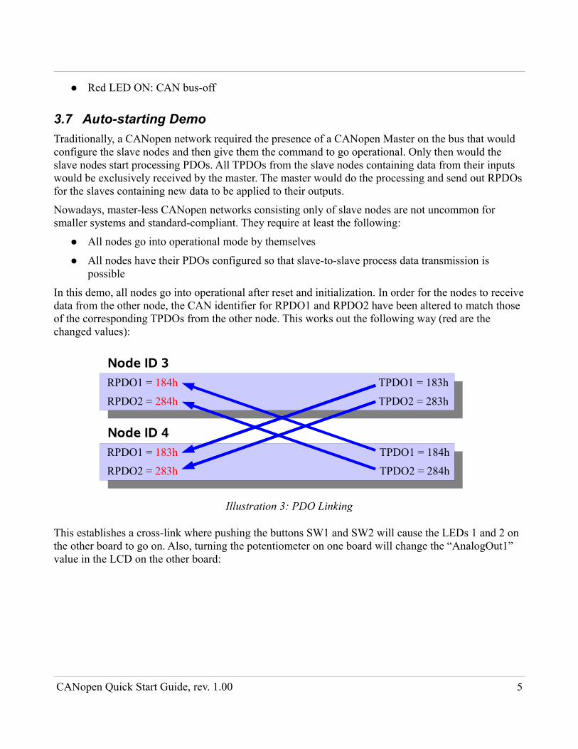
In this demo, all nodes go into operational after reset and initialization. In order for the nodes to receive data from the other node, the CAN identifier for RPDO1 and RPDO2 have been altered to match those of the corresponding TPDOs from the other node. This works out the following way (red are the changed values):
Node ID 3RPDO1 = 184h TPDO1 = 183h
RPDO2 = 284h TPDO2 = 283h
Node ID 4RPDO1 = 183h TPDO1 = 184h
RPDO2 = 283h TPDO2 = 284h
Illustration 3: PDO Linking
This establishes a cross-link where pushing the buttons SW1 and SW2 will cause the LEDs 1 and 2 on the other board to go on. Also, turning the potentiometer on one board will change the “AnalogOut1” value in the LCD on the other board:
CANopen Quick Start Guide, rev. 1.00 5
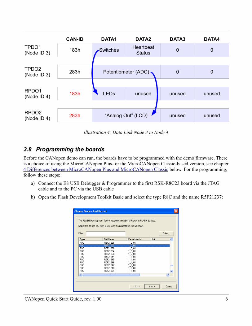
CAN-ID DATA1 DATA2 DATA3 DATA4TPDO1(Node ID 3) 183h Switches Heartbeat
Status 0 0
TPDO2(Node ID 3) 283h Potentiometer (ADC) 0 0
RPDO1(Node ID 4) 183h LEDs unused unused unused
RPDO2(Node ID 4) 283h “Analog Out” (LCD) unused unused
Illustration 4: Data Link Node 3 to Node 4
3.8 Programming the boardsBefore the CANopen demo can run, the boards have to be programmed with the demo firmware. There is a choice of using the MicroCANopen Plus- or the MicroCANopen Classic-based version, see chapter 4 Differences between MicroCANopen Plus and MicroCANopen Classic below. For the programming, follow these steps:
a) Connect the E8 USB Debugger & Programmer to the first RSK-R8C23 board via the JTAG cable and to the PC via the USB cable
b) Open the Flash Development Toolkit Basic and select the type R8C and the name R5F21237:
CANopen Quick Start Guide, rev. 1.00 6
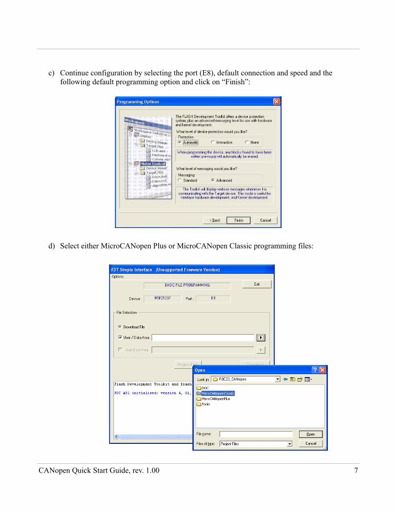
c) Continue configuration by selecting the port (E8), default connection and speed and the following default programming option and click on “Finish”:
d) Select either MicroCANopen Plus or MicroCANopen Classic programming files:
CANopen Quick Start Guide, rev. 1.00 7

e) Select a ..._node_3.mot file (here: MicroCANopen Plus)
f) Select “Program Flash”. When asked whether the E8 should power the board, don't check this option if you use the external power supply, otherwise. The programming should finish successfully:
g) Repeat all steps with the second RSK-R8C23 board and choose a ..._node_4.mot fileIn order to run the demo, connect both boards as described in chapter 2 Setup and Connections.
3.9 Standalone DemoThe programming files that end with ..._standalone.mot behave differently in the following way:
CANopen Quick Start Guide, rev. 1.00 8

● Nodes do not automatically go into operational mode after reset and initialization
● With the MicroCANopen Classic version, all TPDOs are configured so that they are not periodically transmitted. Only change-of-state is active. One has to configure the Event Timer to cause them to be periodically transmitted. Alternatively, TPDOs may be polled using CAN remote transmission (RTR) messages. See chapter 5.2 Poll TPDOs.
The standalone demos require an NMT command before they start processing PDOs (see chapter 5.1 Switch operating modes). Only programming files with node ID 3 are available.
4 Differences between MicroCANopen Plus and MicroCANopen ClassicSo what is the difference between these two? Let's compare the available features:
Feature MicroCANopen Plus
MicroCANopen Classic
All CANopen baud rates supported
Network Management state machine with autostart option
Heartbeat producer, [1017H]
Heartbeat consumer, [1016H]
Node Guarding responses (some drivers)
Setup via hard-coding in program
Setup via CANopen Task Setup File (read/write to [1F50H])
Object Dictionary support for data types of up to 4 bytes (expedited SDO transfer)
Object Dictionary support for any data type (segmented SDO transfer)
Object Dictionary support for any data type (SDO block transfer)
PDO default configuration can be hard-coded
Dynamic PDO Communication Parameters (write to [14xxH] and [18xxH] allowed)
Dynamic PDO Mapping Parameters (write to [16xxH] and [1AxxH] allowed) *)
Store PDO parameters in non-volatile memory ([1010H], [1011H] and [1020H])
CANopen Quick Start Guide, rev. 1.00 9
Feature MicroCANopen Plus
MicroCANopen Classic
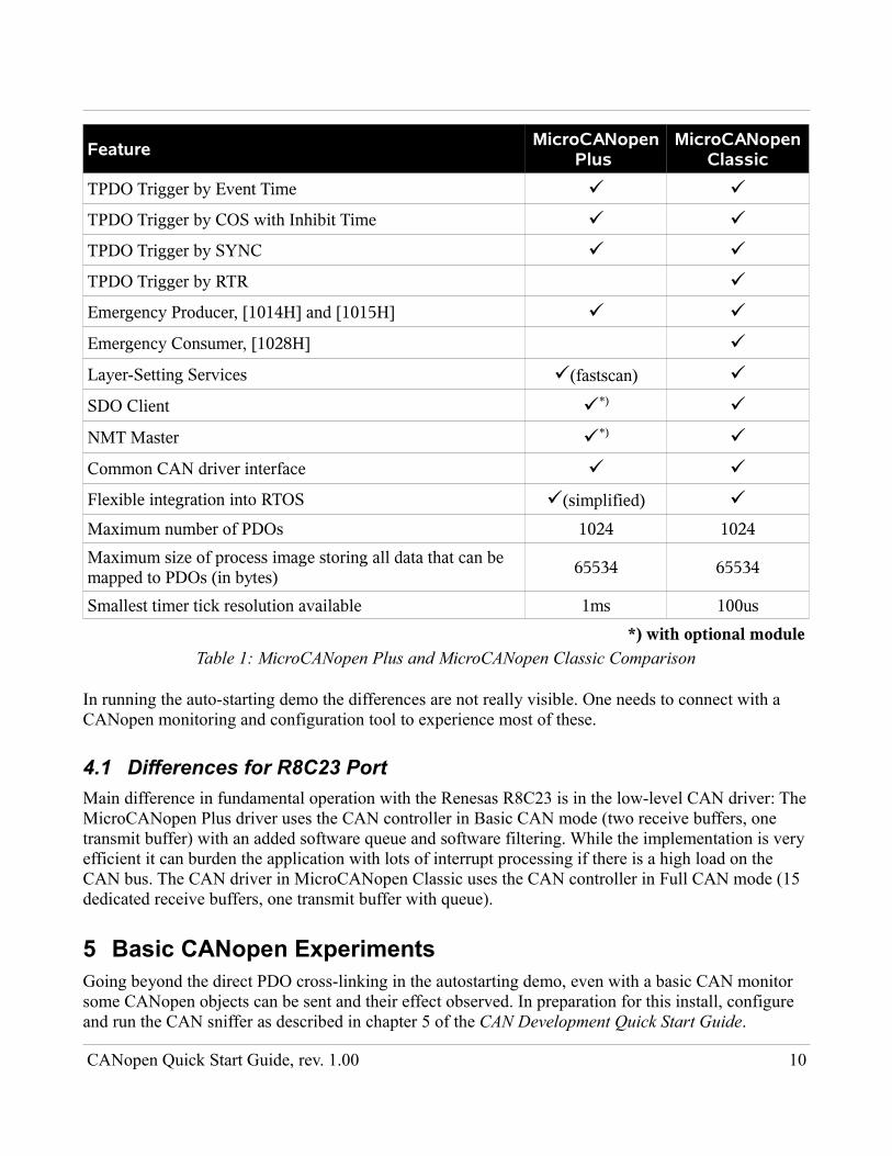
TPDO Trigger by Event Time
TPDO Trigger by COS with Inhibit Time
TPDO Trigger by SYNC
TPDO Trigger by RTR
Emergency Producer, [1014H] and [1015H]
Emergency Consumer, [1028H]
Layer-Setting Services (fastscan)
SDO Client *)
NMT Master *)
Common CAN driver interface
Flexible integration into RTOS (simplified)
Maximum number of PDOs 1024 1024Maximum size of process image storing all data that can be mapped to PDOs (in bytes) 65534 65534
Smallest timer tick resolution available 1ms 100us*) with optional module
Table 1: MicroCANopen Plus and MicroCANopen Classic Comparison
In running the auto-starting demo the differences are not really visible. One needs to connect with a CANopen monitoring and configuration tool to experience most of these.
4.1 Differences for R8C23 PortMain difference in fundamental operation with the Renesas R8C23 is in the low-level CAN driver: The MicroCANopen Plus driver uses the CAN controller in Basic CAN mode (two receive buffers, one transmit buffer) with an added software queue and software filtering. While the implementation is very efficient it can burden the application with lots of interrupt processing if there is a high load on the CAN bus. The CAN driver in MicroCANopen Classic uses the CAN controller in Full CAN mode (15 dedicated receive buffers, one transmit buffer with queue).
5 Basic CANopen ExperimentsGoing beyond the direct PDO cross-linking in the autostarting demo, even with a basic CAN monitor some CANopen objects can be sent and their effect observed. In preparation for this install, configure and run the CAN sniffer as described in chapter 5 of the CAN Development Quick Start Guide.
CANopen Quick Start Guide, rev. 1.00 10
5.1 Switch operating modesBy sending the NMT Master message, all or individual nodes can be switched into different operating modes.
CAN-ID DATA1 DATA2NMT 0h Command Node ID
Illustration 5: NMT Master Message
The available commands are:
Command Byte Command1 Operational2 Stopped
128 (80h) Pre-operational129 (81h) Reset Node130 (82h) Reset Communication
Table 2: MicroCANopen Plus and MicroCANopen Classic Comparison
If Node ID is 0 the command is effective for all nodes simultaneously, otherwise only for the node specified.
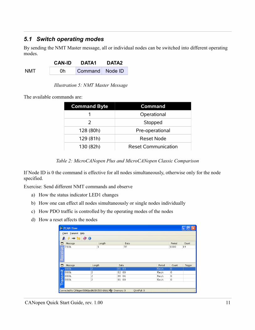
Exercise: Send different NMT commands and observe
a) How the status indicator LED1 changes
b) How one can effect all nodes simultaneously or single nodes individually
c) How PDO traffic is controlled by the operating modes of the nodes
d) How a reset affects the nodes
CANopen Quick Start Guide, rev. 1.00 11
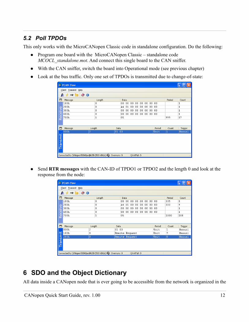
5.2 Poll TPDOsThis only works with the MicroCANopen Classic code in standalone configuration. Do the following:
● Program one board with the MicroCANopen Classic – standalone code MCOCL_standalone.mot. And connect this single board to the CAN sniffer.
● With the CAN sniffer, switch the board into Operational mode (see previous chapter)
● Look at the bus traffic. Only one set of TPDOs is transmitted due to change-of-state:
● Send RTR messages with the CAN-ID of TPDO1 or TPDO2 and the length 0 and look at the response from the node:
6 SDO and the Object DictionaryAll data inside a CANopen node that is ever going to be accessible from the network is organized in the
CANopen Quick Start Guide, rev. 1.00 12

Object Dictionary, a kind of look-up table, organized using a 16-bit index and an 8-bit subindex. This data includes:
● Configuration
● Process Data
● Manufacturer-specific data
On the network, the method to read from and write to Object Dictionary entries in a node is called Service Data Object (SDO). For each Node ID, two CAN message IDs are reserved to establish this communication channel.
The standard method to describe the implementation of an Object Dictionary in a node is called Electronic Data Sheet (EDS), an ASCII text file with sections to describe general information plus all implemented index/subindex combinations, their data type, access modes and default values.
The 16-bit index is divided into ranges that are reserved for certain purposes, for instance 1000h-1FFFh contains the Communication Profile to set-up PDOs, Heartbeats etc.
If a system integrator configures a node, the EDS file is assigned to the node in an appropriate tool, then entries in the Object Dictionary are written until the configuration is right. This configuration is then stored in an extended version of the EDS file called Device Configuration File (DCF). The DCF is a “personalized” version of the EDS for one individual node and can be used to restore the configuration any time later on.
The R8C23 CANopen demo implementations come with matching EDS files in the EDS\ subdirectories for the two stacks. In addition, the MicroCANopen Plus version has DCF files for the three builds (node 3, node 4 and standalone) because for this stack, a software tool can be used to generate the configuration code in one single step, directly from the DCF file. This tool is called CANopen Architect EDS, and an evaluation version is in the Tools\ subdirectory. The evaluation version can be used to browse the EDS and DCF files and get familiar with the structure.
CANopen Quick Start Guide, rev. 1.00 13
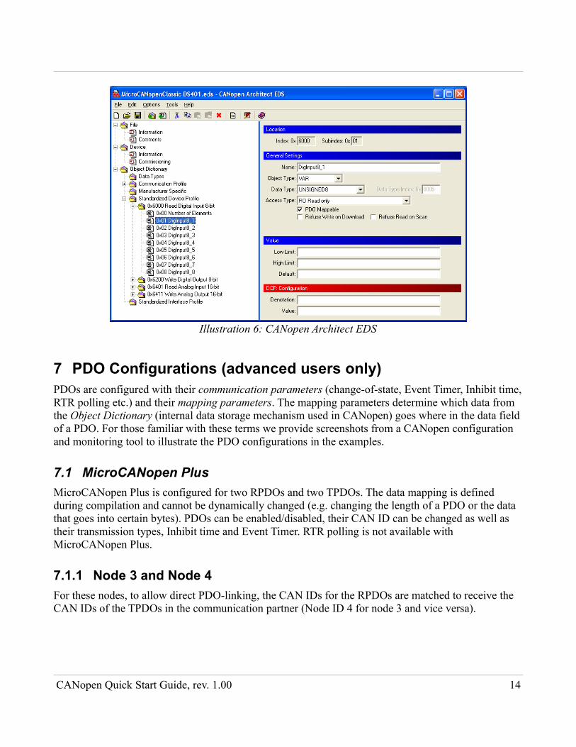
7 PDO Configurations (advanced users only)PDOs are configured with their communication parameters (change-of-state, Event Timer, Inhibit time, RTR polling etc.) and their mapping parameters. The mapping parameters determine which data from the Object Dictionary (internal data storage mechanism used in CANopen) goes where in the data field of a PDO. For those familiar with these terms we provide screenshots from a CANopen configuration and monitoring tool to illustrate the PDO configurations in the examples.
7.1 MicroCANopen PlusMicroCANopen Plus is configured for two RPDOs and two TPDOs. The data mapping is defined during compilation and cannot be dynamically changed (e.g. changing the length of a PDO or the data that goes into certain bytes). PDOs can be enabled/disabled, their CAN ID can be changed as well as their transmission types, Inhibit time and Event Timer. RTR polling is not available with MicroCANopen Plus.
7.1.1 Node 3 and Node 4For these nodes, to allow direct PDO-linking, the CAN IDs for the RPDOs are matched to receive the CAN IDs of the TPDOs in the communication partner (Node ID 4 for node 3 and vice versa).
CANopen Quick Start Guide, rev. 1.00 14
Illustration 6: CANopen Architect EDS
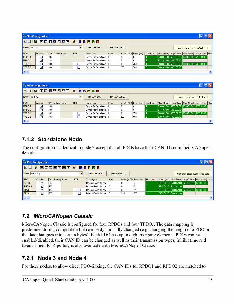
7.1.2 Standalone NodeThe configuration is identical to node 3 except that all PDOs have their CAN ID set to their CANopen default.
7.2 MicroCANopen ClassicMicroCANopen Classic is configured for four RPDOs and four TPDOs. The data mapping is predefined during compilation but can be dynamically changed (e.g. changing the length of a PDO or the data that goes into certain bytes). Each PDO has up to eight mapping elements. PDOs can be enabled/disabled, their CAN ID can be changed as well as their transmission types, Inhibit time and Event Timer. RTR polling is also available with MicroCANopen Classic.
7.2.1 Node 3 and Node 4For these nodes, to allow direct PDO-linking, the CAN IDs for RPDO1 and RPDO2 are matched to
CANopen Quick Start Guide, rev. 1.00 15
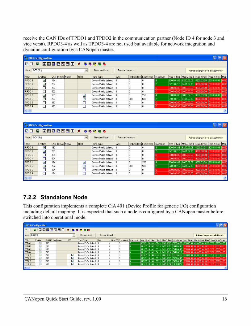
receive the CAN IDs of TPDO1 and TPDO2 in the communication partner (Node ID 4 for node 3 and vice versa). RPDO3-4 as well as TPDO3-4 are not used but available for network integration and dynamic configuration by a CANopen master.
7.2.2 Standalone NodeThis configuration implements a complete CiA 401 (Device Profile for generic I/O) configuration including default mapping. It is expected that such a node is configured by a CANopen master before switched into operational mode.
CANopen Quick Start Guide, rev. 1.00 16
8 Resource FootprintsThe CANopen stacks can be highly customized so that features that are not needed are not compiled. The following are numbers taken directly out of the mapping files for the demo builds that have most available features enabled. Not included in the RAM requirements are:
● Process Image. This can be quite small or large depending on the application. It holds all PDO data that you transmit plus values from the Object Dictionary. For this demo we didn't optimize it's size. For small applications add about 30-40 bytes.
● Non-volatile storage simulation RAM. The MicroCANopen stacks implement the function to store parameters into non-volatile storage space (typically EEPROM) using Object Dictionary entries [1010h], [1011h] and [1020h] according to CiA standard 301. Since there is no EEPROM on the board, a dedicated RAM area is used to simulate it's behavior. This works through reset but not through power-cycle. This RAM is not required for real applications.
8.1 MicroCANopen PlusCode and constant data: 13,573 bytes
RAM: 1,148 bytes (from that 188 for CAN FIFOs which can be configured)
8.2 MicroCANopen ClassicCode and constant data: 15,900 bytes
RAM: 1,625 bytes (from that 60 for CAN transmit queue which can be configured)
CANopen Quick Start Guide, rev. 1.00 17