canopen programming with ipos intelligent drives - …...any technosoft drive for your application...
TRANSCRIPT

iPOS
CANopen Programming
User Manual
Technosoft 2015


T E C H N O S O F T
iPOS CANopen Programming
User Manual
P091.063.iPOS.UM.0615
Technosoft S.A. Avenue des Alpes 20
CH-2000 NEUCHATEL Switzerland
Tel.: +41 (0) 32 732 5500 Fax: +41 (0) 32 732 5504
[email protected] www.technosoftmotion.com

Read This First Whilst Technosoft believes that the information and guidance given in this manual is correct, all parties must rely upon their own skill and judgment when making use of it. Technosoft does not assume any liability to anyone for any loss or damage caused by any error or omission in the work, whether such error or omission is the result of negligence or any other cause. Any and all such liability is disclaimed.
All rights reserved. No part or parts of this document may be reproduced or transmitted in any form or by any means, electrical or mechanical including photocopying, recording or by any information-retrieval system without permission in writing from Technosoft S.A. About This Manual This book describes how to program Technosoft iPOS family of intelligent drives using CANopen protocol. The iPOS drives are confirming to CiA 301 v4.2 application layer and communication profile, CiA WD 305 v.2.2.131 Layer Setting Services and to CiA DSP 402 v3.0 device profile for drives and motion control, now included in IEC 61800-7-1 Annex A, IEC 61800-7-201 and IEC 61800-7-301 standards. The manual presents the object dictionary associated with these three profiles. The manual also explains how to combine the Technosoft Motion Language (TML) commands and the CANopen protocol commands in order to distribute the application between the CANopen master and the Technosoft drives. In order to operate the Technosoft iPOS drives, you need to pass through 3 steps: Step 1 Hardware installation
Step 2 Drive setup using Technosoft EasySetUp software for drive commissioning
Step 3 Motion programming using one of the options:
A CANopen master
The drive built-in motion controller executing a Technosoft Motion Language (TML) program developed using Technosoft EasyMotion Studio software A TML_LIB motion library for PCs (Windows or Linux)
A TML_LIB motion library for PLCs
A distributed control approach which combines the above options, like for example a host calling motion functions programmed on the drives in TML
Scope of This Manual
This manual applies to the iPOS family of Technosoft intelligent drives. Notational Conventions This document uses the following conventions:
1 Available only with the firmware F514x.
© Technosoft 2015 iPOS CANopen Programming III

TML – Technosoft Motion Language iPOS – a Technosoft drive family, the code is usually iPOSxx0x xx-CAN IU – drive/motor internal units ControlWord.5 – bit 5 of ControlWord data cs – command specifier Axis ID = CAN ID = COB ID – the unique number allocated to each drive in a network. Related Documentation
Help of the EasySetUp software – describes how to use EasySetUp to quickly setup any Technosoft drive for your application using only 2 dialogues. The output of EasySetUp is a set of setup data that can be downloaded into the drive EEPROM or saved on a PC file. At power-on, the drive is initialized with the setup data read from its EEPROM. With EasySetUp it is also possible to retrieve the complete setup information from a previously programmed drive. EasySetUp can be downloaded free of charge from Technosoft web page
Technical Reference Manual of each iPOS drive version – describes the hardware including the technical data, the connectors, the wiring diagrams needed for installation and detailed setup information.
Motion Programming using EasyMotion Studio (part no. P091.034.ESM.UM.xxxx) – describes how to use the EasyMotion Studio to create motion programs using in Technosoft Motion Language (TML). EasyMotion Studio platform includes EasySetUp for the drive/motor setup, and a Motion Wizard for the motion programming. The Motion Wizard provides a simple, graphical way of creating motion programs and automatically generates all the TML instructions. With EasyMotion Studio you can fully benefit from a key advantage of Technosoft drives – their capability to execute complex motions without requiring an external motion controller, thanks to their built-in motion controller. A demo version of EasyMotion Studio (with EasySetUp part fully functional) can be downloaded free of charge from Technosoft web page
TML_LIB v2.0 (part no. P091.040.v20.UM.xxxx) – explains how to program in C, C++, C#, Visual Basic or Delphi Pascal a motion application for the Technosoft intelligent drives using TML_LIB v2.0 motion control library for PCs. The manual includes over 40 ready-to-run examples that can be executed on Windows or Linux (x86 and x64)
TML_LIB_LabVIEW v2.0 (part no. P091.040.LABVIEW.v20.UM.xxxx) – explains how to program in LabVIEW a motion application for the Technosoft intelligent drives using TML_LIB_LabVIEW v2.0 motion control library for PCs. The manual includes over 40 ready-to-run examples.
TML_LIB_S7 (part no. P091.040.S7.UM.xxxx) – explains how to program a PLC Siemens series S7-300 or S7-400 with a motion application for the Technosoft intelligent drives using TML_LIB_S7 motion control library. The manual includes over 40 ready-to-run examples. The library is PLCOpen compatible.
© Technosoft 2015 iPOS CANopen Programming IV

TML_LIB_CJ1 (part no. P091.040.CJ1.UM.xxxx) – explains how to program a PLC Omron series CJ1 with a motion application for the Technosoft intelligent drives using TML_LIB_CJ1 motion control library for PCs. The manual includes over 40 ready-to-run examples. The library is PLCOpen compatible.
TML_LIB_X20 (part no. P091.040.X20.UM.xxxx) – explains how to program in a PLC B&R series X20 a motion application for the Technosoft intelligent drives using TML_LIB_X20 motion control library for PLCs. The TML_LIB_X20 library is IEC61131-3 compatible
TechnoCAN (part no. P091.063.TechnoCAN.UM.xxxx) – presents TechnoCAN protocol – an extension of the CANopen communication profile used for TML commands
© Technosoft 2015 iPOS CANopen Programming V
If you Need Assistance …
If you want to … Contact Technosoft at … Visit Technosoft online
World Wide Web: http://www.technosoftmotion.com/
Receive general information or assistance (see Note) Ask questions about product operation or report suspected problems (see Note) Make suggestions about, or report errors in documentation (see Note)
World Wide Web: http://www.technosoftmotion.com/ Email: [email protected] Fax: (41) 32 732 55 04 Email: [email protected] Mail: Technosoft SA Avenue des Alpes 20 CH-2000 NEUCHATEL, Switzerland
© Technosoft 2015 iPOS CANopen Programming VI

Contents 1. Getting Started ........................................................................................................................ 1
1.1. Setting up the drive using EasySetUp or EasyMotion Studio ............................................. 1 1.1.1. What are EasySetUp and EasyMotion Studio? .......................................................... 1 1.1.2. Installing EasySetUp or EasyMotion Studio ................................................................ 2 1.1.3. Establishing serial communication with the drive ....................................................... 2 1.1.4. Choosing the drive, motor and feedback configuration .............................................. 3 1.1.5. Introducing motor data ................................................................................................ 4 1.1.6. Commissioning the drive ............................................................................................ 5 1.1.7. Downloading setup data to drive/motor ...................................................................... 6 1.1.8. Saving setup data in a file ........................................................................................... 7 1.1.9. Creating a .sw file with the setup data ........................................................................ 7 1.1.10. Checking and updating setup data via .sw files with a CANopen master ................... 7 1.1.11. Testing and monitoring the drive behavior .................................................................. 8 1.1.12. TechnoCAN Extension ............................................................................................... 8
1.2. Changing the drive Axis ID (Node ID) ................................................................................ 8 1.3. Setting the current limit .................................................................................................... 10 1.4. Setting the CANbus rate .................................................................................................. 11 1.5. CANopen factor group setting .......................................................................................... 12 1.6. Using the built-in Motion Controller and TML ................................................................... 13
1.6.1. Technosoft Motion Language Overview ................................................................... 13 2. Layer Setting Services (LSS protocol) ................................................................................ 14
2.1. Overview .......................................................................................................................... 14 2.2. Configuration services ...................................................................................................... 16
2.2.1. Switch State Global ................................................................................................... 16 2.2.2. Switch State Selective .............................................................................................. 17 2.2.3. Configure Node ID .................................................................................................... 18 2.2.4. Configure Bit Timing Parameters.............................................................................. 19 2.2.5. Activate Bit Timing Parameters ................................................................................ 20 2.2.6. Store Configuration Protocol ..................................................................................... 21 2.2.7. Inquire Identity Vendor ID ......................................................................................... 21 2.2.8. Inquire Identity Product Code ................................................................................... 22 2.2.9. Inquire Identity Revision Number .............................................................................. 22 2.2.10. Inquire Identity Serial Number .................................................................................. 23 2.2.11. Inquire Identity Node ID ............................................................................................ 23 2.2.12. Identify Remote Slave ............................................................................................... 24 2.2.13. Identify non-configured Remote Slave ...................................................................... 25
3. CAN and the CANopen protocol .......................................................................................... 26 3.1. CAN Architecture ............................................................................................................. 26 3.2. Accessing CANopen devices ........................................................................................... 27
3.2.1. Object dictionary ....................................................................................................... 27 3.2.2. Object access using index and sub-index ................................................................ 28 3.2.3. Service Data Objects (SDO) ..................................................................................... 28 3.2.4. Process Data Objects (PDO) .................................................................................... 29
© Technosoft 2015 iPOS CANopen Programming VII

3.3. Objects that define SDOs and PDOs ............................................................................... 29 3.3.1. Object 1200h: Server SDO Parameter ..................................................................... 29 3.3.2. Object 1400h: Receive PDO1 Communication Parameters ..................................... 30 3.3.3. Object 1401h: Receive PDO2 Communication parameters ..................................... 31 3.3.4. Object 1402h: Receive PDO3 Communication parameters ..................................... 32 3.3.5. Object 1403h: Receive PDO4 Communication parameters ..................................... 33 3.3.6. Object 1600h: Receive PDO1 Mapping Parameters ................................................ 34 3.3.7. Object 1601h: Receive PDO2 Mapping Parameters ................................................ 35 3.3.8. Object 1602h: Receive PDO3 Mapping Parameters ................................................ 36 3.3.9. Object 1603h: Receive PDO4 Mapping Parameters ................................................ 37 3.3.10. Object 1800h: Transmit PDO1 Communication parameters .................................... 38 3.3.11. Object 1801h: Transmit PDO2 Communication parameters .................................... 39 3.3.12. Object 1802h: Transmit PDO3 Communication parameters .................................... 40 3.3.13. Object 1803h: Transmit PDO4 Communication parameters .................................... 42 3.3.14. Object 1A00h: Transmit PDO1 Mapping Parameters ............................................... 43 3.3.15. Object 1A01h: Transmit PDO2 Mapping Parameters ............................................... 44 3.3.16. Object 1A02h: Transmit PDO3 Mapping Parameters ............................................... 45 3.3.17. Object 1A03h: Transmit PDO4 Mapping Parameters ............................................... 46 3.3.18. Object 207Dh: Dummy ............................................................................................. 47
3.4. Dynamic mapping of the PDOs ........................................................................................ 47 3.5. RxPDOs mapping example .............................................................................................. 48 3.6. TxPDOs mapping example .............................................................................................. 49
4. Network Management ........................................................................................................... 52 4.1. Overview .......................................................................................................................... 52
4.1.1. Network Management (NMT) State Machine ........................................................... 52 4.1.2. Device control ........................................................................................................... 53
4.1.2.1. Enter Pre-Operational ........................................................................................ 54 4.1.2.2. Reset communication ........................................................................................ 54 4.1.2.3. Reset Node ........................................................................................................ 54 4.1.2.4. Start Remote Node ............................................................................................ 55 4.1.2.5. Stop Remote Node ............................................................................................ 55
4.1.3. Device monitoring ..................................................................................................... 56 4.1.3.1. Node guarding protocol ..................................................................................... 56 4.1.3.2. Heartbeat protocol ............................................................................................. 56 4.1.3.3. Bootup protocol.................................................................................................. 56
4.1.4. Synchronization between devices ............................................................................. 56 4.1.5. Emergency messages .............................................................................................. 57
4.2. Network management objects ......................................................................................... 58 4.2.1. Object 1001h: Error Register .................................................................................... 58 4.2.2. Object 1003h: Pre-defined error field ........................................................................ 59 4.2.3. Object 1005h: COB-ID of the SYNC Message ......................................................... 60 4.2.4. Object 1006h: Communication Cycle Period ............................................................ 61 4.2.5. Object 1010h: Store parameters ............................................................................... 61 4.2.6. Object 1011h: Restore parameters........................................................................... 62 4.2.7. Object 100Ch: Guard Time ....................................................................................... 63
© Technosoft 2015 iPOS CANopen Programming VIII

4.2.8. Object 100Dh: Life Time Factor ................................................................................ 64 4.2.9. Object 1013h: High Resolution Time Stamp............................................................. 64 4.2.10. Object 2004h: COB-ID of the High-resolution time stamp ........................................ 65 4.2.11. Configure the drive as a SYNC master Example ...................................................... 66 4.2.12. Object 1014h: COB-ID Emergency Object ............................................................... 66 4.2.13. Object 1017h: Producer Heartbeat Time .................................................................. 68
5. Drive control and status ....................................................................................................... 69 5.1. Overview .......................................................................................................................... 69 5.2. Drive control and status objects ....................................................................................... 72
5.2.1. Object 6040h: Control Word ..................................................................................... 72 5.2.2. Object 6041h: Status Word ...................................................................................... 74 5.2.3. Object 1002h: Manufacturer Status Register ............................................................ 76 5.2.4. Object 6060h: Modes of Operation ........................................................................... 77 5.2.5. Object 6061h: Modes of Operation Display .............................................................. 77
5.3. Error monitoring ............................................................................................................... 78 5.3.1. Object 2000h: Motion Error Register ........................................................................ 78 5.3.2. Object 2002h: Detailed Error Register ...................................................................... 80 5.3.3. Object 605Ah: Quick stop option code ..................................................................... 81 5.3.4. Object 605Bh: Shutdown option code ....................................................................... 82 5.3.5. Object 605Ch: Disable operation option code .......................................................... 82 5.3.6. Object 605Dh: Halt option code ................................................................................ 83 5.3.7. Object 605Eh: Fault reaction option code ................................................................. 84 5.3.8. Object 6007h: Abort connection option code ............................................................ 85
5.4. Digital I/O control and status objects................................................................................ 85 5.4.1. Object 60FDh: Digital inputs ..................................................................................... 85 5.4.2. Object 60FEh: Digital outputs ................................................................................... 87
5.4.2.1. Example: setting digital outputs ......................................................................... 88 5.4.3. Object 2045h: Digital outputs status ......................................................................... 89 5.4.4. Object 2102h: Brake status ...................................................................................... 89 5.4.5. Object 2046h: Analogue input: Reference ................................................................ 90 5.4.6. Object 2047h: Analogue input: Feedback ................................................................. 90 5.4.7. Object 2055h: DC-link voltage .................................................................................. 91 5.4.8. Object 2058h: Drive Temperature ............................................................................ 91 5.4.9. Object 2108h: Filter variable 16bit ............................................................................ 92
5.5. Protections Setting Objects .............................................................................................. 94 5.5.1. Object 607Dh: Software position limit ....................................................................... 94 5.5.2. Object 2050h: Over-current protection level ............................................................. 95 5.5.3. Object 2051h: Over-current time out ........................................................................ 95 5.5.4. Object 2052h: Motor nominal current ....................................................................... 96 5.5.5. Object 2053h: I2t protection integrator limit .............................................................. 96 5.5.6. Object 2054h: I2t protection scaling factor ............................................................... 98 5.5.7. Object 207Fh: Current limit1...................................................................................... 99
5.6. Step Loss Detection for Stepper Open Loop configuration .............................................. 99 5.6.1. Object 2083h: Encoder Resolution for step loss protection .................................... 100 5.6.2. Object 2084h: Stepper Resolution for step loss protection ..................................... 100 5.6.3. Enabling step loss detection protection .................................................................. 102
© Technosoft 2015 iPOS CANopen Programming IX

5.6.4. Step loss protection setup....................................................................................... 103 5.6.5. Recovering from step loss detection fault ............................................................... 103 5.6.6. Remarks about Factor Group settings when using step the loss detection ............ 103
5.7. Drive info objects ............................................................................................................ 103 5.7.1. Object 1000h: Device Type ..................................................................................... 103 5.7.2. Object 6502h: Supported drive modes ................................................................... 104 5.7.3. Object 1008h: Manufacturer Device Name............................................................. 105 5.7.4. Object 100Ah: Manufacturer Software Version ...................................................... 106 5.7.5. Object 2060h: Software version of a TML application ............................................ 106 5.7.6. Object 1018h: Identity Object .................................................................................. 107
5.8. Miscellaneous Objects ................................................................................................... 108 5.8.1. Object 2025h: Stepper current in open-loop operation ........................................... 108 5.8.2. Object 2026h: Stand-by current for stepper in open-loop operation ....................... 109 5.8.3. Object 2027h: Timeout for stepper stand-by current .............................................. 109 5.8.4. Object 2075h: Position triggers ............................................................................... 110 5.8.5. Object 2085h: Position triggered outputs ................................................................ 111 5.8.6. Object 2076h: Save current configuration .............................................................. 112 5.8.7. Object 208Bh: Sin AD signal from Sin/Cos encoder ............................................... 113 1.1.1 Object 208Ch: Cos AD signal from Sin/Cos encoder ............................................. 113 5.8.8. Object 208Eh: Auxiliary Settings Register .............................................................. 114 5.8.9. Object 2100h: Number of steps per revolution ....................................................... 114 5.8.10. Object 2101h: Number of microsteps per step ....................................................... 115 5.8.11. Object 2103h: Number of encoder counts per revolution ....................................... 115
6. Factor group ........................................................................................................................ 116 6.1. Factor group objects ...................................................................................................... 116
6.1.1. Object 607Eh: Polarity ............................................................................................ 116 6.1.2. Object 6089h: Position notation index .................................................................... 117 6.1.3. Object 608Ah: Position dimension index ................................................................ 118 6.1.4. Object 608Bh: Velocity notation index .................................................................... 118 6.1.5. Object 608Ch: Velocity dimension index ................................................................ 119 6.1.6. Object 608Dh: Acceleration notation index ............................................................. 119 6.1.7. Object 608Eh: Acceleration dimension index ......................................................... 120 6.1.8. Object 206Fh: Time notation index ......................................................................... 120 6.1.9. Object 2070h: Time dimension index ..................................................................... 121 6.1.10. Object 6093h: Position factor .................................................................................. 122 6.1.11. Object 6094h: Velocity encoder factor .................................................................... 122 6.1.12. Object 6097h: Acceleration factor ........................................................................... 123 6.1.13. Object 2071h: Time factor ...................................................................................... 124
7. Homing Mode ...................................................................................................................... 126 7.1. Overview ........................................................................................................................ 126 7.2. Homing methods ............................................................................................................ 127
7.2.1. Method 1: Homing on the Negative Limit Switch. ................................................... 127 7.2.2. Method 2: Homing on the Positive Limit Switch. ..................................................... 127 7.2.3. Methods 3 and 4: Homing on the Positive Home Switch and Index Pulse. ............ 128 7.2.4. Methods 5 and 6: Homing on the Negative Home Switch and Index Pulse. .......... 129 7.2.5. Methods 7 to14: Homing on the Negative Home Switch and Index Pulse. ............ 129
© Technosoft 2015 iPOS CANopen Programming X

7.2.6. Methods 17 to 30: Homing without an Index Pulse................................................. 131 7.2.7. Methods 33 and 34: Homing on the Index Pulse .................................................... 133 7.2.8. Method 35: Homing on the Current Position ........................................................... 133 7.2.9. Method -1: Homing on the Negative Mechanical Limit and Index Pulse ................ 134
7.2.9.1. Method -1 based on motor current increase ................................................... 134 7.2.9.2. Method -1 based on step loss detection .......................................................... 134
7.2.10. Method -2: Homing on the Positive Mechanical Limit and Index Pulse .................. 135 7.2.10.1. Method -2 based on motor current increase ................................................... 135 7.2.10.2. Method -2 based on step loss detection .......................................................... 136
Figure 7.14 Homing on the Positive Mechanical Limit and Index Pulse detecting a control error 136 7.2.11. Method -3: Homing on the Negative Mechanical Limit without an Index Pulse. ..... 137
7.2.11.1. Method -3 based on motor current increase ................................................... 137 7.2.11.2. Method -3 based on step loss detection .......................................................... 137
7.2.12. Method -4: Homing on the Positive Mechanical Limit without an Index Pulse. ....... 138 7.2.12.1. Method -4 based on motor current increase ................................................... 138 7.2.12.2. Method -4 based on step loss detection .......................................................... 139
7.3. Homing Mode Objects ................................................................................................... 140 7.3.1. Control word in homing mode ................................................................................. 140 7.3.2. Status word in homing mode .................................................................................. 140 7.3.3. Object 607Ch: Home offset .................................................................................... 141 7.3.4. Object 6098h: Homing method ............................................................................... 142 7.3.5. Object 6099h: Homing speeds ............................................................................... 142 7.3.6. Object 609Ah: Homing acceleration ....................................................................... 143 7.3.7. Object 207Bh: Homing current threshold ................................................................ 144 7.3.8. Object 207Ch: Homing current threshold time ....................................................... 144
7.4. Homing example ............................................................................................................ 145 8. Position Profile Mode ......................................................................................................... 147
8.1. Overview ........................................................................................................................ 147 8.1.1. Discrete motion profile (change set immediately = 0) ............................................. 147 8.1.2. Continuous motion profile (change set immediately = 1) ........................................ 148 8.1.3. Control word in profile position mode...................................................................... 148 8.1.4. Status word in profile position mode ....................................................................... 149
8.2. Position Profile Mode Objects ........................................................................................ 150 8.2.1. Object 607Ah: Target position ................................................................................ 150 8.2.2. Object 6081h: Profile velocity ................................................................................. 150 8.2.3. Object 6083h: Profile acceleration .......................................................................... 151 8.2.4. Object 6085h: Quick stop deceleration ................................................................... 151 8.2.5. Object 2023h: Jerk time .......................................................................................... 152 8.2.6. Object 6086h: Motion profile type ........................................................................... 152 8.2.7. Object 6062h: Position demand value .................................................................... 153 8.2.8. Object 6063h: Position actual internal value ........................................................... 153 8.2.9. Object 6064h: Position actual value ........................................................................ 153 8.2.10. Object 6065h: Following error window .................................................................... 154 8.2.11. Object 6066h: Following error time out ................................................................... 154
© Technosoft 2015 iPOS CANopen Programming XI
8.2.12. Object 6067h: Position window ............................................................................... 155 8.2.13. Object 6068h: Position window time ....................................................................... 155 8.2.14. Object 60F4h: Following error actual value ............................................................ 156 8.2.15. Object 60FCh: Position demand internal value ...................................................... 156 8.2.16. Object 2022h: Control effort .................................................................................... 157 8.2.17. Object 2081h: Set/Change the actual motor position ............................................. 157 8.2.18. Object 2088h: Actual internal position from sensor on motor ................................. 157 1.1.2 Object 208Dh: Auxiliary encoder position ............................................................... 158
8.3. Position Profile Examples .............................................................................................. 159 8.3.1. Absolute trapezoidal example ................................................................................. 159 8.3.2. Absolute Jerk-limited ramp profile example ............................................................ 161
9. Interpolated Position Mode ................................................................................................ 164 9.1. Overview ........................................................................................................................ 164
9.1.1. Internal States ......................................................................................................... 164 9.1.2. Control word in interpolated position mode ............................................................. 165 9.1.3. Status word in interpolated position mode .............................................................. 166
9.2. Interpolated Position Objects ......................................................................................... 166 9.2.1. Object 60C0h: Interpolation sub mode select ......................................................... 166 9.2.2. Object 60C1h: Interpolation data record ................................................................. 167 9.2.3. Object 2072h: Interpolated position mode status ................................................... 170 9.2.4. Object 2073h: Interpolated position buffer length ................................................... 171 9.2.5. Object 2074h: Interpolated position buffer configuration ........................................ 171 9.2.6. Object 2079h: Interpolated position initial position .................................................. 172 9.2.7. Object 207Ah: Interpolated position 1st order time .................................................. 173 9.2.8. Loading the interpolated points ............................................................................... 173
9.3. PT absolute movement example ................................................................................... 174 9.4. PVT absolute movement example ................................................................................. 177 9.5. PVT relative movement example ................................................................................... 183
10. Cyclic Synchronous Position (CSP) mode.................................................................... 188 10.1. Overview ..................................................................................................................... 188
10.1.1. Control word in synchronous position mode ........................................................... 188 10.1.2. Status word in cyclic synchronous position mode ................................................... 189
10.2. Cyclic Synchronous Position Mode Objects ............................................................... 189 10.2.1. Object 60C2h: Interpolation time period ................................................................. 189 10.2.2. Object 2086h: Limit speed for CSP ........................................................................ 191
10.3. Cyclic Synchronous Position Mode example .............................................................. 192 11. Velocity Profile Mode ...................................................................................................... 200
11.1. Overview ..................................................................................................................... 200 11.1.1. Control word in profile velocity mode ...................................................................... 200 11.1.2. Status word in profile velocity mode ....................................................................... 200
11.2. Velocity Mode Objects ................................................................................................ 201 11.2.1. Object 6069h: Velocity sensor actual value ............................................................ 201 11.2.2. Object 606Bh: Velocity demand value .................................................................... 201 11.2.3. Object 606Ch: Velocity actual value ....................................................................... 202
© Technosoft 2015 iPOS CANopen Programming XII

11.2.4. Object 606Fh: Velocity threshold ............................................................................ 202 11.2.5. Object 60FFh: Target velocity ................................................................................. 203 11.2.6. Object 60F8h: Max slippage ................................................................................... 203 11.2.7. Object 2005h: Max slippage time out ..................................................................... 204 11.2.8. Object 2087h: Actual internal velocity from sensor on motor ................................. 204
11.3. Speed profile example ................................................................................................ 205 12. Electronic Gearing Position (EGEAR) Mode ................................................................. 207
12.1. Overview ..................................................................................................................... 207 12.1.1. Control word in electronic gearing position mode (slave axis) ................................ 208 12.1.2. Status word in electronic gearing position mode .................................................... 208
12.2. Gearing Position Mode Objects .................................................................................. 209 12.2.1. Object 2010h: Master settings ................................................................................ 209 12.2.2. Object 2012h: Master resolution ............................................................................. 209 12.2.3. Object 2013h: EGEAR multiplication factor ............................................................ 210 12.2.4. Object 2017h: Master actual position ..................................................................... 211 12.2.5. Object 2018h: Master actual speed ........................................................................ 211 12.2.6. Object 201Dh: External Reference Type ................................................................ 212
12.3. Electronic gearing through CAN example .................................................................. 213 13. Electronic Camming Position (ECAM) Mode ................................................................ 216
13.1. Overview ..................................................................................................................... 216 13.1.1. Control word in electronic camming position mode ................................................ 217 13.1.2. Status word in electronic camming position mode.................................................. 217
13.2. Electronic Camming Position Mode Objects .............................................................. 218 13.2.1. Object 2019h: CAM table load address .................................................................. 218 13.2.2. Object 201Ah: CAM table run address ................................................................... 218 13.2.3. Object 201Bh: CAM offset ...................................................................................... 219 13.2.4. Object 206Bh: CAM: input scaling factor ................................................................ 219 13.2.5. Object 206Ch: CAM: output scaling factor .............................................................. 220 13.2.6. Building a CAM profile and saving it as an .sw file example ................................... 220
13.2.6.1. Extracting the cam data from the motion and setup .sw file ............................ 227 13.2.6.2. Downloading a CAM .sw file with objects 2064h and 2065h example .............. 228
13.3. Electronic camming through CAN example ............................................................... 229 14. External Reference Position Mode ................................................................................ 233
14.1. Overview ..................................................................................................................... 233 14.1.1. Control word in external reference position mode .................................................. 233 14.1.2. Status word in external reference position mode .................................................... 234
14.2. External Reference Position Mode Objects ................................................................ 234 14.2.1. Object 201Ch: External On-line Reference ............................................................ 234
15. External Reference Speed Mode .................................................................................... 235 15.1. Overview ..................................................................................................................... 235
15.1.1. Control word in external reference speed mode ..................................................... 235 15.1.2. Status word in external reference speed mode ...................................................... 235
16. External Reference Torque Mode .................................................................................. 237
© Technosoft 2015 iPOS CANopen Programming XIII

16.1. Overview ..................................................................................................................... 237 16.1.1. Control word in external reference torque mode .................................................... 237 16.1.2. Status word in external reference torque mode ...................................................... 237
16.2. External reference torque mode objects .................................................................... 238 16.2.1. Object 6071h: Target torque ................................................................................... 238 16.2.2. Object 6077h: Torque actual value ......................................................................... 238 16.2.3. Object 207Eh: Current actual value ........................................................................ 239
17. Touch probe functionality .............................................................................................. 240 17.1. Overview ..................................................................................................................... 240 17.2. Touch probe objects ................................................................................................... 240
17.2.1. Object 60B8h: Touch probe function ...................................................................... 240 17.2.2. Object 60B9h: Touch probe status ......................................................................... 242 17.2.3. Object 60BAh: Touch probe 1 positive edge .......................................................... 243 17.2.4. Object 60BBh: Touch probe 1 negative edge ......................................................... 244 17.2.5. Object 60BCh: Touch probe 2 positive edge .......................................................... 244 17.2.6. Object 60BDh: Touch probe 2 negative edge ......................................................... 245 17.2.7. Object 2104h: Auxiliary encoder function ............................................................... 245 17.2.8. Object 2105h: Auxiliary encoder status .................................................................. 246 17.2.9. Object 2106h: Auxiliary encoder captured position positive edge .......................... 247 17.2.10. Object 2107h: Auxiliary encoder captured position negative edge ......................... 248
18. Data Exchange between CANopen master and drives ................................................ 249 18.1. Checking Setup Data Consistency ............................................................................. 249 18.2. Image Files Format and Creation ............................................................................... 249 18.3. Data Exchange Objects .............................................................................................. 250
18.3.1. Object 2064h: Read/Write Configuration Register ................................................. 250 18.3.2. Object 2065h: Write 16/32 bits data at address set in Read/Write Configuration Register 251 18.3.3. Object 2066h: Read 16/32 bits data from address set in Read/Write Configuration Register 251 18.3.4. Object 2067h: Write data at specified address ....................................................... 252 18.3.5. Object 2069h: Checksum configuration register ..................................................... 253 18.3.6. Object 206Ah: Checksum read register .................................................................. 253
18.4. Downloading an image file (.sw) to the drive using CANopen objects example ........ 254 18.5. Checking and loading the drive setup via .sw file using CANopen commands example. 255
19. Advanced features ........................................................................................................... 258 19.1. Using EasyMotion Studio............................................................................................ 258
19.1.1. Starting a new project ............................................................................................. 258 19.1.2. Choosing the drive, motor and feedback configuration .......................................... 259 19.1.3. Downloading setup data to drive/motor .................................................................. 261
19.2. Using TML Functions to Split Motion between Master and Drives ............................. 261 19.2.1. Build TML functions within EasyMotion Studio ....................................................... 261 19.2.2. TML Function Objects ............................................................................................. 262
19.2.2.1. Object 2006h: Call TML Function .................................................................... 262
© Technosoft 2015 iPOS CANopen Programming XIV

19.3. Executing TML programs ........................................................................................... 263 19.3.1. Object 2077h: Execute TML program ..................................................................... 263
19.4. Loading Automatically Cam Tables Defined in EasyMotion Studio ............................ 263 19.4.1. CAM table structure ................................................................................................ 264
19.5. Customizing the Homing Procedures ......................................................................... 265 19.6. Customizing the Drive Reaction to Fault Conditions .................................................. 265
Appendix A: Object Dictionary by Index .................................................................................. 266
© Technosoft 2015 iPOS CANopen Programming XV


1. Getting Started
1.1. Setting up the drive using EasySetUp or EasyMotion Studio
1.1.1. What are EasySetUp and EasyMotion Studio? EasySetUp is a PC software platform for the setup of the Technosoft drives. Via EasySetUp you can quickly commission any Technosoft drive for your application using only 2 dialogues. The output of EasySetUp is the setup data that can be stored into the drive EEPROM or saved on a PC file. The setup data contains all the information needed to configure and parameterize a Technosoft drive. At power-on, the drive is initialized with the setup data read from its EEPROM. EasySetUp may also be used to retrieve the setup data previously stored in a drive EEPROM.
EasySetUp also includes evaluation tools like: Data Logger, Control Panel and Command Interpreter which help you to quickly measure, check and analyze your drive commissioning. EasyMotion Studio is an advanced PC software platform that can be used both for the drives setup and for their motion programming. With EasyMotion Studio you can fully benefit from a key advantage of the Technosoft drives – their capability to execute stand-alone complex motion programs thanks to their built-in motion controller. EasyMotion Studio includes EasySetUp for the drive setup, and a Motion Wizard for the motion programming. The Motion Wizard provides a simple, graphical way of creating motion programs written in Technosoft Motion Language (TML). It automatically generates all the TML instructions, hence you don’t need to learn or write any TML code. Via TML you can:
• Set various motion modes • Change the motion modes and/or the motion parameters • Execute homing sequences • Control the program flow through:
Conditional jumps and calls of TML functions Interrupts generated on pre-defined or programmable conditions (protections
triggered, transitions of limit switch or capture inputs, etc.) Waits for programmed events to occur
• Handle digital I/O and analogue input signals • Execute arithmetic and logic operations
The output of EasyMotion Studio is the application data that can be loaded into the drive EEPROM or saved on a file. The application data includes both the setup data and the TML motion program. Using TML, you can really simplify complex applications, by distributing the intelligence between the master and the drives. Thus, instead of trying to command each step of an axis movement from the master, you can program the drives using TML to execute complex tasks, and inform the master when these tasks have been completed. Important: You need EasyMotion Studio full version, only if you use TML programming. For electronic camming applications, you need the free of charge EasyMotion Studio demo version to format the cam data. For all the other cases, you can use the free of charge EasySetUp
© Technosoft 2015 iPOS CANopen Programming 1

1.1.2. Installing EasySetUp or EasyMotion Studio EasySetUp and EasyMotion Studio demo version can be downloaded free of charge from Technosoft web page. Both include an Update via Internet tool through which you can check if your software version is up-to-date, and when necessary download and install the latest updates.
EasyMotion Studio demo version includes a fully functional version of EasySetUp, hence you don’t need to install both of them. You can install the EasyMotion Studio full version in 2 ways: Using the CD provided by Technosoft. In this case, after installation, use the Update via Internet tool to check for the latest updates; Transforming EasyMotion Studio demo into a full version, by introducing in the application menu command Help | Registration Info the serial number provided by Technosoft. The 2nd option is especially convenient if the EasyMotion Studio demo version is al ready installed. Remark: The next paragraphs present only the drive commissioning with EasySetUp. Par. 19.1.1. shows how to perform the same steps with EasyMotion Studio demo or full version.
1.1.3. Establishing serial communication with the drive EasySetUp communicates with the drive via an RS-232 serial link or CAN interface. If your PC has no serial port, use an USB to RS232 adapter. For the serial connections refer to the drive Technical Reference manual. If the drive or the Starter Kit board accompanying the drive has a 9-pin serial port, use a standard 9-wire, non-inverting (one to one) serial cable. Figure 1.1 EasySetUp - Opening window
© Technosoft 2015 iPOS CANopen Programming 2
All Technosoft drives with CAN interface have a unique AxisID (address) for serial communication. The AxisID value is by default 255 or it is set by the levels of the AxisID selection inputs, when these exist.
Remark: When first started, EasySetUp tries to communicate via RS-232 and COM1 with a drive having axis ID=255 (default communication settings). When it is connected to your PC port COM1 via an RS-232 cable, the communication shall establish automatically.
If the communication is established, EasySetUp displays in the status bar (the bottom line) the text “Online” plus the axis ID of your drive/motor and its firmware version. Otherwise the text displayed is “Offline” and a communication error message tells you the error type. In this case, use menu command Communication | Setup to check/change your PC communication settings. Check the following:
Channel Type: RS232 or CAN interface CAN Protocol: CANopen or TechnoCAN Port: Select the COM port where you have connected the drive Baud rate: can be any value for RS232 and it is automatically detected. For best performance, we recommend to use the highest value: 115200. For a CAN interface, choose the default baud rate 500 Kbps.
Remark: Once the communication is established, you can reopen the Communication | Setup dialogue and change the baud rate
Axis ID of drive/motor: connected to PC (autodetected) for RS232 or the CAN Axis ID which is by default 127 in CANopen.
Close the Communication | Setup dialogue with OK and check the status bar. If the communication is established, the text “Online” shall occur in the status bar. If the communication is still not established, check the serial cable connections and the drive power. Refer to the Technical reference manual of the drive for details.
Remark: Reopen the Communication | Setup dialogue and press the Help button. Here you can find detailed information about communication setup and troubleshooting.
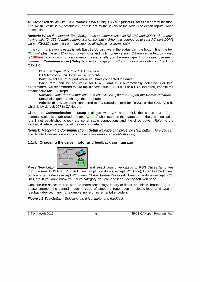
1.1.4. Choosing the drive, motor and feedback configuration
Press New button and select your drive category: iPOS Drives (all drives from the new iPOS line), Plug In Drives (all plug-in drives, except iPOS line), Open Frame Drives, (all open-frame drives except iPOS line), Closed Frame Drives (all close-frame drives except iPOS line), etc. If you don’t know your drive category, you can find it on Technosoft web page.
Continue the selection tree with the motor technology: rotary or linear brushless, brushed, 2 or 3 phase stepper, the control mode in case of steppers (open-loop or closed-loop) and type of feedback device, if any (for example: none or incremental encoder).
Figure 1.2 EasySetUp – Selecting the drive, motor and feedback
© Technosoft 2015 iPOS CANopen Programming 3

The selection opens 2 setup dialogues: for Motor Setup and for Drive setup through which you can introduce your motor data and commission the drive, plus several predefined control panels customized for the drive selected.
1.1.5. Introducing motor data
Figure 1.3 shows the Motor setup dialogue where you can introduce the data of your motor and the associated sensors. Use the Guideline Assistant, and follow the steps described. This will guide you through the whole process of introducing and/or checking the motor and sensors data. Use the Next button to see the next guideline step and the Previous button to return to the previous step. Data introduction is accompanied by a series of tests having as goal to check the connections to the drive and/or to determine or validate a part of the motor and sensors parameters.
When finished, click on Drive Setup button to move to the 2nd dialogue.
Remark: Press the Help button from the Motor setup dialogue for detailed information
Figure 1.3 EasySetUp – Introducing motor data
© Technosoft 2015 iPOS CANopen Programming 4

1.1.6. Commissioning the drive Figure 1.4 shows the Drive setup dialogue where you can configure and parameterize the drive for your application. Use the Guideline Assistant, and follow the steps described. This will guide you through the whole process of setting up the drive. Use the Next button to see the next guideline step and the Previous button to return to the previous step. Close the Drive setup dialogue with OK to preserve all the changes done in both motor and drive setup dialogues.
Remarks:
1) Press the Help button from the Drive setup dialogue for detailed information 2) Set the motor Over current protection level below the motor Peak current value. This
shall protect the motor against accidental high currents bypassing ite Peak current value 3) When motor I2t protection is enabled, set its Over current value over the motor Nominal
current
© Technosoft 2015 iPOS CANopen Programming 5
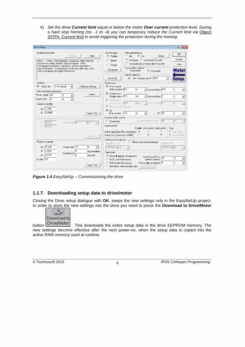
4) Set the drive Current limit equal or below the motor Over current protection level. During a hard stop homing (no. -1 to -4) you can temporary reduce the Current limit via Object 207Fh: Current limit to avoid triggering the protection during the homing
Figure 1.4 EasySetUp – Commissioning the drive
1.1.7. Downloading setup data to drive/motor Closing the Drive setup dialogue with OK, keeps the new settings only in the EasySetUp project. In order to store the new settings into the drive you need to press the Download to Drive/Motor
button . This downloads the entire setup data in the drive EEPROM memory. The new settings become effective after the next power-on, when the setup data is copied into the active RAM memory used at runtime.
© Technosoft 2015 iPOS CANopen Programming 6

1.1.8. Saving setup data in a file
It is also possible to Save the setup data on your PC and use it later. To summarize, you can define or change the setup data in the following ways:
create a new setup data by going through the motor and drive dialogues use setup data previously saved in the PC upload setup data from a drive/motor EEPROM memory
1.1.9. Creating a .sw file with the setup data Once you have validated your setup, you can create with the menu command Setup | Create EEPROM Programmer File a software file (with extension .sw) which contains all the setup data to write in the EEPROM of your drive.
A software file is a text file that can be read with any text editor. It contains blocks of data separated by an empty line. Each block of data starts with the block start address, followed by the block data values ordered in ascending order at consecutive addresses: first data value – what to write in drive EEPROM memory at block start address, second data – what to write at block start address + 1, third data – what to write at block start address +2 etc. All data are hexadecimal 16- bit values (maximum 4 hexadecimal digits). Each line contains a single data value. When less then 4 hexadecimal digits are shown, the value must be right justified. For example 92 is 0x0092.
The .sw file can be programmed into a drive:
from a CANopen master, using the communication objects for writing data into the drive EEPROM (see Chapter 18 for detailed example)
using the EEPROM Programmer tool, which comes with EasySetUp but may also be installed separately. The EEPROM Programmer was specifically designed for repetitive fast and easy programming of .sw files into the Technosoft drives during production
1.1.10. Checking and updating setup data via .sw files with a CANopen master You can program a CANopen master to automatically check after power on if all the Technosoft drives connected to the CAN network have the right setup data stored in their EEPROM. The comparison shall be done with the reference .sw files of each axis. These need to be loaded into the CANopen master. There fastest way to compare a .sw file with a drive EEPROM contents is by comparing the checksums computed on the .sw file data with those computed by the drive on the same address range. In case of mismatch, the reference .sw file has to be reloaded into the drive by the CANopen master. Par 18.4 and 18.5 present examples how to program a .sw file in a drive and how to check its consistency versus a .sw reference file.
© Technosoft 2015 iPOS CANopen Programming 7

1.1.11. Testing and monitoring the drive behavior You can use the Data Logger or the Control Panel evaluation tools to quickly measure and analyze your application behavior. In case of errors like protections triggered, check the Drive Status control panel to find the cause.
1.1.12. TechnoCAN Extension In order to take full advantage of the powerful Technosoft Motion Language (TML) built into the intelligent drives, Technosoft has developed an extension to CANopen, called TechnoCAN through which TML commands can be exchanged with the drives. Thanks to TechnoCAN you can inspect or reprogram any of the Technosoft drives from a CANopen network using EasySetUp or EasyMotion Studio and an RS-232 link between your PC and any of the drives.
TechnoCAN uses only message identifiers outside of the range used by the CANopen predefined connection set (as defined by CiA DS301 v4.2.0). Thus, TechnoCAN protocol and CANopen protocol can co-exist and communicate simultaneously on the same physical CAN bus, without disturbing each other.
1.2. Changing the drive Axis ID (Node ID) The axis ID of an iPOS drive can be set in 3 ways:
Hardware (H/W) Software (via Setup)– any value between 1 and 255, stored in the setup table.
Software (via CANopen master) – using CiA-3051 protocol Remark:
• If the drive is in CANopen mode, a Node ID value above 127 is automatically converted into 255 and the drive is set with CAN communication “non-configured” mode waiting for a CANopen master to configure it using CiA-305 protocol. A “non-configured” drive answers only to CiA-305 commands. All other CANopen commands are ignored and transmission of all other CANopen messages (including boot-up) is disabled. The Ready (green) LED will flash at 1 second time intervals while in this mode.
In absence of a CANopen master, you can get out a drive from “non-configured” mode, by setting another axis ID between 1 and 127, either by Hardware or by Software (via Setup).
1 CiA 305 protocol is available only on firmware F514C and above.
© Technosoft 2015 iPOS CANopen Programming 8

The axis ID is initialized at power on, using the following algorithm: a) If a valid setup table exists, and this setup table was created with the Axis ID Selection
checkbox checked in the Drive Setup dialogue (see above) – with the value read from the setup table. This value can be an axis number 1 to 255 or can indicate that axis ID will be set according with the AxisID inputs levels. If the drive is set in CANopen mode and the Axis ID is over 127 it is converted into 255 and the drive enters in CAN communication “non-configured” mode. The Ready (green) LED will flash at 1 second time intervals while in this mode.
b) If a valid the setup table exists, and this was created with the Axis ID Selection checkbox unchecked in the Drive Setup dialogue (see above) – with the last value set either from a valid setup table or by a CANopen master via CiA-305 protocol. This value can be an axis number 1 to 255 for TMLCAN, 1 to 127 for CANopen, or can indicate that axis ID will be set according with the AxisID inputs levels
c) If the setup table is invalid, with the last value set either from a valid setup table or by a CANopen master via CiA-305 protocol. This value can be an axis number 1 to 255 for TMLCAN, 1 to 127 for CANopen, or can indicate that axis ID will be set according with the AxisID inputs levels
d) If the setup table is invalid, there is no previous axis ID set from a valid setup table or by a CANopen master, according with the AxisID inputs levels
© Technosoft 2015 iPOS CANopen Programming 9

Remark: If you don’t know the axis ID set in a drive, you can find it in the following way:
a) Connect the drive via a serial RS232 link to a PC where EasySetUp or EasyMotion Studio are installed
b) With the drive powered, open EasySetUp or EasyMotion Studio and check the status bar. If communication with the drive is established, the status bar displays Online in green and nearby the drive’s Axis ID. If the status bar displays Offline in red, execute menu command “Communication|Setup…” and in the dialogue opened select at “Channel Type” RS232 and at “Axis ID of drive/motor connected to PC” the option Autodetected. After closing the dialogue with OK, communication with the drive shall be established and the status bar shall display the drive’s Axis ID
c) If the access to the drive with the unknown Axis ID is difficult, but this drive is connected via CANbus with other Technosoft drives having an easier access, connect your PC serially to one of the other drives. Use EasySetUp or EasyMotion Studio menu command Communication | Scan Network to find the axis IDs of all the Technosoft drives present in the network.
1.3. Setting the current limit In Easy Setup if a feedback device is used, the user can choose a current limit. It is advised to use a lower value than the one set in current protection.
The current limit can also be set using Object 207Fh: Current limit.
© Technosoft 2015 iPOS CANopen Programming 10

1.4. Setting the CANbus rate The iPOS drives accept the following CAN rates: 125Kbps, 250 Kbps, 500kbps and 1Mbps. Using the Drive Setup dialogue you can choose the initial CAN rate after power on. This information is stored in the setup table The CAN rate is initialized using the following algorithm: If a valid setup table exists, and this setup table was created with the Set baud rate checkbox checked in the Drive Setup dialogue (see above) – with the value read from the setup table. This value can be one of the above 4 values or the firmware default (F/W default) which is 500kbs If a valid setup table exists, and this setup table was created with the Set baud rate checkbox unchecked in the Drive Setup dialogue (see above) – with the last value set either from a valid setup table or by a CANopen master via CiA-305 protocol If the setup table is invalid, with the last value set either from a valid setup table or by a CANopen master via CiA-305 protocol.
If the setup table is invalid, there is no previous CAN rate set from a valid setup table or by a CANopen master, with f/w default value which is 500kbs
© Technosoft 2015 iPOS CANopen Programming 11

1.5. CANopen factor group setting1 By pressing the CANopen Settings button, you can choose the initial values after power on for the CANopen factor group settings. The factor group settings describe the scaling factors for position, speed, acceleration and time objects. In the factor group dialogue you can select the units to use when writing to these objects or reading them. You can either choose one of the standard units defined in the CANopen standard CiA402 or define your own unit.
1 Note: this option does not work if TMLCAN mode is set
© Technosoft 2015 iPOS CANopen Programming 12

In the last case, it is your responsibility to set the factor numerator and divisor as well as its dimension and notation index. The factor group settings are stored in the setup table. By default the drive uses its internal units. The correspondence between the drive internal units and the SI units is presented in the drives’ user manual.
1.6. Using the built-in Motion Controller and TML One of the key advantages of the Technosoft drives is their capability to execute complex motions without requiring an external motion controller. This is possible because Technosoft drives offer in a single compact package both a state of art digital drive and a powerful motion controller.
1.6.1. Technosoft Motion Language Overview Programming motion directly on a Technosoft drive requires to create and download a TML (Technosoft Motion Language) program into the drive memory. The TML allows you to:
• Set various motion modes (profiles, PVT, PT, electronic gearing or camming, etc.)
• Change the motion modes and/or the motion parameters
• Execute homing sequences
• Control the program flow through:
Conditional jumps and calls of TML functions
Interrupts generated on pre-defined or programmable conditions (protections triggered, transitions of limit switch or capture inputs, etc.)
Waits for programmed events to occur
• Handle digital I/O and analogue input signals
• Execute arithmetic and logic operations
• Perform data transfers between axes
• Control motion of an axis from another one via motion commands sent between axes
• Send commands to a group of axes (multicast). This includes the possibility to start simultaneously motion sequences on all the axes from the group
© Technosoft 2015 iPOS CANopen Programming 13
• Synchronize all the axes from a network
In order to program a motion using TML you need EasyMotion Studio software platform.
Chapter 19 describes in detail how the TML features can be combined with the CANopen programming.
2. Layer Setting Services (LSS protocol)1 By using layer setting services, the CANopen node-ID and/or the bit timing settings of a LSS slave device may be configured via the CAN network without using any hardware components such as jumpers or DIP-switches. The CANopen device that can configure other devices via CANopen network is called a LSS Master. There must be only one (active) LSS master in a network. The CANopen device that will be configured by the LSS Master via CANopen network is called a LSS Slave.
An LSS Slave can be identified by its unique LSS address. The LSS address consists of the sub objects Vendor ID, Product Code, Revision Number and Serial Number of the CANopen “Identity Object” with index 1018h. In the network, there must not be other LSS Slaves possessing the same LSS address.
With this unique LSS address an individual CANopen device can be allocated within the network. The Node ID is valid if it is in the range of 0x01…0x7F. The value 0xFF indicates not configured CANopen devices.
Communication between LSS Master and LSS Slaves is accomplished by LSS protocols which use only two COB-IDs:
• LSS master messages from LSS Master to LSS Slaves (COB-ID 0x7E5) • LSS slave messages from the LSS Slaves to LSS Master (COB-ID 0x7E4).
2.1. Overview The table below provides an overview on the LSS commands, including details on whether they may be used in states “Waiting” and “Configuration”. To change the LSS state, the LSS services Switch State Global or Switch State Selective may be used.
1 LSS protocol is available only in the F514x firmware
© Technosoft 2015 iPOS CANopen Programming 14

Table 2.1 Drive State Transitions
Command Specifier
Services LSS waiting state
LSS configuration state
0x04 Switch State Global yes yes 0x40
Switch state selective procedure
Vendor ID yes no 0x41 Product Code yes no 0x42 Revision Number yes no 0x43 Serial Number yes no 0x11 Configure node-ID no yes 0x13 Configure bit timing parameters no yes 0x15 Activate bit timing parameters no yes 0x17 Store configuration no yes 0x5A
Inquire LSS address protocol
Identity Vendor ID no yes 0x5B Identity Product Code no yes 0x5C Identity Revision Number no yes 0x5D Identity Serial Number no yes 0x5E Inquire node-ID protocol no yes 0x46
Identify remote slave procedure
Vendor ID yes yes 0x47 Product Code yes yes 0x48 Revision Number Low yes yes 0x49 Revision Number High yes yes 0x4A Serial Number Low yes yes 0x4B Serial Number High yes yes 0x4C Identify non-configured Remote Slave yes yes
© Technosoft 2015 iPOS CANopen Programming 15

2.2. Configuration services The LSS configuration services are used to configure the node-ID or bit rate.
2.2.1. Switch State Global Switches all LSS slave devices in the network into LSS “Waiting” state or LSS “Configuration” state.
The service is unconfirmed.
0 1 2 3 4 5 6 7
LSS master LSS slave
cs0x04 mode reserved
CAN-ID = 0x7E5
Figure 2.1 LSS – Switch State Global
cs 0x04 Command Specifier for Switch State Global command
mode 0 Switch to LSS state waiting
1 Switch to LSS state configuration
© Technosoft 2015 iPOS CANopen Programming 16

2.2.2. Switch State Selective Changed state of one LSS Slave from “Waiting” to “Configuration”.
LSS command specifier can be: - 0x40 to submit the Vendor ID, - 0x41 to submit the Product Code, - 0x42 to submit the Revision Number, - 0x43 to submit the Serial Number
To selectively switch a target LSS slave to “Configuration” state, all the Switch State Selective commands must be sent and must contain the same data as found in the “Identity Object”, index 1018h, of the target drive.
The service is confirmed. The LSS slave sends the command specifier 0x44 meaning it has entered “Configuration” state.
0 1 2 3 4 5 6 7
LSS master LSS slave
cs0x40 Vendor ID reserved
CAN-ID = 0x7E5
0 1 2 3 4 5 6 7
cs0x41 Product Code reserved
CAN-ID = 0x7E5
0 1 2 3 4 5 6 7
cs0x42 Revision Number reserved
CAN-ID = 0x7E5
0 1 2 3 4 5 6 7
cs0x43 Serial Number reserved
CAN-ID = 0x7E5
0 1 2 3 4 5 6 7
cs0x44 reserved
CAN-ID = 0x7E4
Figure 2.2 LSS – Switch State Selective
© Technosoft 2015 iPOS CANopen Programming 17

2.2.3. Configure Node ID Configures the Node ID (of value 1…127 or 255).
The LSS Master can set the LSS Slave’s Node ID only in LSS configuration state. The LSS Master is responsible to switch a single LSS Slave into LSS state “Configuration” (with Switch State Selective) before requesting this service. With this service, the LSS Salve’s Node ID can take only values between 1 and 127 (valid Node ID) or 255 (set slave to not-configured).
If the Node ID is set to 255 (0xFF), the LSS slave remains in NMT Initialization sub-state “reset communication” and waits in LSS waiting state for further commands. During this waiting state, the LSS slave is not allowed to send messages, except when LSS replies are needed.
To activate the new node ID, the LSS master has to send the NMT command “Reset communication”. To store the new node ID in the non-volatile memory, the LSS master has to use LSS Store Configuration protocol before resetting the communication or the node.
0 1 2 3 4 5 6 7
LSS master LSS slave
cs0x11
node-ID reserved
CAN-ID = 0x7E5
0 1 2 3 4 5 6 7
cs0x11 reserved
CAN-ID = 0x7E4errorcode
specificerror
Figure 2.3 LSS – Configure Node ID
cs 0x11 Command specifier for configure node-ID protocol
mode 0 Protocol successfully completed
1 Node ID out of range value
specific error always 0
© Technosoft 2015 iPOS CANopen Programming 18

2.2.4. Configure Bit Timing Parameters By means of the service configure bit timing parameters, the LSS Master can configure new bit timing on a single or multiple LSS Slaves. The new bit timing will be active only after LSS Activate Bit Timing Parameters command or LSS Store Configuration Protocol followed by node reset commands.
0 1 2 3 4 5 6 7
LSS master LSS slave
cs0x13
tableselector reserved
CAN-ID = 0x7E5
0 1 2 3 4 5 6 7
cs0x13 reserved
CAN-ID = 0x7E4errorcode
specificerror
tableindex
Figure 2.4 LSS – Configure Bit Timing Parameters
Table 2.2 Supported CAN bitrates
Value Bit Rate 0 1 Mbit/s 2 500 kbit/s 3 250 kbit/s 4 125 kbit/s
cs 0x13 Command specifier for configure bit timing parameters protocol
table selector always 0
table index CAN bit rate codes
error code 0 Protocol successfully completed
1 Node ID out of range value
specific error always 0
© Technosoft 2015 iPOS CANopen Programming 19

2.2.5. Activate Bit Timing Parameters Activates bit timing parameters selected with Configure Bit Timing Parameters service.
Switch delay = specifies the duration [in ms] of the two delay periods of equal length. The first period is until the bit timing parameters switch is done. The second period is the time before sending any new CAN message. They are necessary to avoid operating the network with different bit rates.
After receiving an activate bit timing command, the LSS slave stops communication. After the first switch delay, communication is switched to the new bit rate. After the second delay, the LSS slave is allowed to transmit messages with the new bit rate active.
0 1 2 3 4 5 6 7
LSS master LSS slave
cs0x13 switch delay reserved
CAN-ID = 0x7E5
Figure 2.5 LSS – Activate Bit Timing Parameters
act
old bit rate
old bit rate
switch delay 1 switch delay 2
p1
p2
switch delay 1 switch delay 2
switch delay 1 switch delay 2
t[ms]
t[ms]
t[ms]
LSS slave 1
LSS slave 2
LSS master new bit rate
new bit rate
new bit rate
act : Activate bit timing parameters command
p1,p2 : Individual processing delay
Figure 2.6 LSS – LSS master and LSS slave timing
© Technosoft 2015 iPOS CANopen Programming 20

2.2.6. Store Configuration Protocol The pending node-ID and bit rate are copied to the persistent node-ID and bit rate in the non-volatile memory. The result is confirmed by the LSS slave with success or failure message.
0 1 2 3 4 5 6 7
LSS master LSS slave
cs0x17 reserved
CAN-ID = 0x7E5
0 1 2 3 4 5 6 7
cs0x17 reserved
CAN-ID = 0x7E4errorcode
specificerror
Figure 2.7 LSS – Store Configuration
2.2.7. Inquire Identity Vendor ID
Reads Vendor ID of LSS slave. The same value can be found in Identity Object, index 1018h, Subindex 01 of target slave.
0 1 2 3 4 5 6 7
LSS master LSS slave
cs0x5A reserved
CAN-ID = 0x7E5
0 1 2 3 4 5 6 7
cs0x5A reserved
CAN-ID = 0x7E4
vendor ID
Figure 2.8 LSS – Inquire Identity Vendor ID
cs 0x17 Store Configuration
error code always 0
specific error always 0
© Technosoft 2015 iPOS CANopen Programming 21

2.2.8. Inquire Identity Product Code
Reads Product Code of LSS slave. The same value can be found in Identity Object, index 1018h, Subindex 02 of target slave.
0 1 2 3 4 5 6 7
LSS master LSS slave
cs0x5B reserved
CAN-ID = 0x7E5
0 1 2 3 4 5 6 7
cs0x5B reserved
CAN-ID = 0x7E4
product code
Figure 2.9 LSS – Inquire Identity Product Code
2.2.9. Inquire Identity Revision Number
Reads Revision Number of LSS slave. The same value can be found in Identity Object, index 1018h, Subindex 03 of target slave.
0 1 2 3 4 5 6 7
LSS master LSS slave
cs0x5C reserved
CAN-ID = 0x7E5
0 1 2 3 4 5 6 7
cs0x5C reserved
CAN-ID = 0x7E4
revision number
Figure 2.10 LSS – Inquire Identity Revision Number
© Technosoft 2015 iPOS CANopen Programming 22

2.2.10. Inquire Identity Serial Number Reads Serial Number of LSS slave. The same value can be found in Identity Object, index 1018h, Subindex 04 of target slave.
0 1 2 3 4 5 6 7
LSS master LSS slave
cs0x5D reserved
CAN-ID = 0x7E5
0 1 2 3 4 5 6 7
cs0x5D reserved
CAN-ID = 0x7E4
serial number
Figure 2.11 LSS – Inquire Identity Serial Number
2.2.11. Inquire Identity Node ID Reads active Node ID of LSS slave.
0 1 2 3 4 5 6 7
LSS master LSS slave
cs0x5E reserved
CAN-ID = 0x7E5
0 1 2 3 4 5 6 7
cs0x5E reserved
CAN-ID = 0x7E4node-
ID
Figure 2.12 LSS – Inquire Identity Node ID
© Technosoft 2015 iPOS CANopen Programming 23

2.2.12. Identify Remote Slave Identifies LSS Salves in the CAN network. The LSS master sends identify remote slave commands containing a single Vendor ID, a single Product Code, and a range of Revision Numbers and Serial Numbers. All LSS Slaves that are within these values (including the boundaries) answer with an Identify Remote Slave response (cs=0x4F). An LSS Slave answers, only after all Identify commands are sent and it is within the correct parameters.
With this protocol, a network search can be implemented on the LSS master. With this method, the LSS address range is set to maximum values, and identifies the number of remote slaves in the network. This range will be split in two sub-areas and identify the slaves again. This process will be repeated until all LSS Slaves have been identified.
0 1 2 3 4 5 6 7
LSS master LSS slave
cs0x46 Vendor ID reserved
CAN-ID = 0x7E5
cs0x47 Product Code
cs0x48 Revision Number low
cs0x49 Revision Number high
cs0x4F reserved
CAN-ID = 0x7E4
cs0x4A Serial Number low
cs0x4B Serial Number high
reservedCAN-ID = 0x7E5
reservedCAN-ID = 0x7E5
reservedCAN-ID = 0x7E5
reservedCAN-ID = 0x7E5
reservedCAN-ID = 0x7E5
0 1 2 3 4 5 6 7
0 1 2 3 4 5 6 7
0 1 2 3 4 5 6 7
0 1 2 3 4 5 6 7
0 1 2 3 4 5 6 7
0 1 2 3 4 5 6 7
Figure 2.13 LSS – Identify Remote Slave
© Technosoft 2015 iPOS CANopen Programming 24

2.2.13. Identify non-configured Remote Slave Allows the LSS master to detect non-configured slave devices in the network. All LSS Slaves without a configured Node ID (0xFF) will answer with a 0x50 command specifier response.
0 1 2 3 4 5 6 7
LSS master LSS slave
cs0x4C reserved
CAN-ID = 0x7E5
0 1 2 3 4 5 6 7
cs0x50 reserved
CAN-ID = 0x7E4
Figure 2.14 LSS – Identify non-configured Remote Slave
© Technosoft 2015 iPOS CANopen Programming 25

3. CAN and the CANopen protocol CAN (Controller Area Network) is a serial bus system used in a broad range of automation control systems. The CAN specifies the data link and the physical connection over which lays the CANopen, a high level protocol specifying how various types of devices can use the CAN network.
3.1. CAN Architecture CAN provides distributed control of the motion application, the control loops are closed locally not on the master controller. The master controller coordinates multiple devices through the commands it sends and receives information about the status of the devices.
Technosoft extended the concept of distributed motion application allowing splitting the motion application between the Technosoft drives and the CANopen master. Using TML the user can build complex motion applications locally, on each drive, leaving on the CANopen master only a high level motion application and thus reducing the CAN master complexity. The master has the vision of the motion application, specific tasks being executed on the Technosoft drives.
Motion application
High level trajectory
generation
Master controller
Technosoft drive
Position Control
Torque Control
Traj
ecto
ry
Gen
erat
ion
CANopen device
Motor Motor
Technosoft drive
Position Control
Torque Control
Traj
ecto
ry
Gen
erat
ion
CAN network
© Technosoft 2015 iPOS CANopen Programming 26

3.2. Accessing CANopen devices A CANopen device is controlled through read/write operations to/from objects performed by a CANopen master (PC or PLC).
3.2.1. Object dictionary The Object Dictionary is a group of objects that describe the complete functionality of a device by way of communication objects and is the link between the communication interface and the application. All communication objects of a device (application data and configuration parameters) are described in the Object Dictionary in a standardized way.
High level motion
application
High level trajectory
generation
Master controller
Motion application
Technosoft drive
Position Control
Torque Control
Traj
ecto
ry
Gen
erat
ion
Motion application
Technosoft drive
Position Control
Torque Control
Traj
ecto
ry
Gen
erat
ion
CANopen device
Motor Motor
CAN network
© Technosoft 2015 iPOS CANopen Programming 27

3.2.2. Object access using index and sub-index The objects defined for a device are accessed using a 16-bit index and an 8-bit sub-index. In case of arrays and records there is an additional sub-index for each element of the array or record.
3.2.3. Service Data Objects (SDO) Service Data Objects are used by CANopen master to access any object from the drive’s Object Dictionary. Both expedited and segmented SDO transfers are supported (see DS301 v4.2.0 for details). The SDOs are typically used for drive configuration after power-on, for PDO mapping and for infrequent low priority communication. SDO transfers are confirmed services. In case of an error, an Abort SDO message is transmitted with one of the codes listed in Table 3.1.
Table 3.1 SDO Abort Codes
Abort code Description
0503 0000h Toggle bit not alternated
0504 0001h Client/server command specifier not valid or unknown
0601 0000h Unsupported access to an object
0602 0000h Object does not exist in the object dictionary
0604 0041h Object cannot be mapped to the PDO
0604 0042h The number and length of the objects to be mapped would exceed PDO length
0604 0043h General parameter incompatibility reason
0604 0047h General internal incompatibility error in the device
0607 0010h Data type does not match, length of service parameter does not match
0607 0012h Data type does not match, length of service parameter too high
0607 0013h Data type does not match, length of service parameter too low
0609 0011h Sub-index does not exist
0609 0030h Value range of parameter exceeded (only for write access)
0609 0031h Value of parameter written too high
0609 0032h Value of parameter written too low
0800 0000h General error
0800 0020h Data cannot be transferred or stored to the application
0800 0021h Data cannot be transferred or stored to the application because of local control
0800 0022h Data cannot be transferred or stored to the application because of the
© Technosoft 2015 iPOS CANopen Programming 28

present device state
3.2.4. Process Data Objects (PDO) Process Data Objects are used for high priority, real-time data transfers between CANopen master and the drives. The PDOs are unconfirmed services and are performed with no protocol overhead. Transmit PDOs are used to send data from the drive, and receive PDOs are used to receive data. The Technosoft drives accept 4 transmit PDOs and 4 receive PDOs. The contents of the PDOs can be set according with the application needs through the dynamic PDO-mapping. This operation can be done during the drive configuration phase using SDOs.
A PDO is defined by two objects: the communication object and the mapping object. The communication object defines the COB-ID of the PDO, the transmission type and the event triggering the transmission. The mapping object contains the descriptions of the objects mapped into the PDO, i.e. the index, sub-index and size of the mapped objects.
3.3. Objects that define SDOs and PDOs
3.3.1. Object 1200h: Server SDO Parameter The object contains the COB-IDs of the messages used for the SDO protocol. The COBID of the SDO packages received by the drive, stored in sub-index 01, is computed as 600h + drive Node ID. The COB ID of the SDO packages sent by the drive, stored in sub-index 02, is computed as 580h + drive Node ID. Object description:
Index 1200h Name Server SDO Parameter Object code RECORD Data type SDO Parameter
Entry description: Sub-index 00h Description Number of entries Access RO PDO mapping No Value range 2 Default value 2
Sub-index 01h
Description SDO receive COB-ID Access RO PDO mapping No Value range UNSIGNED32
© Technosoft 2015 iPOS CANopen Programming 29

Default value 600h + Node-ID
Sub-index 02h
Description SDO transmit COB-ID Access RO PDO mapping No Value range UNSIGNED32 Default value 580h + Node-ID
3.3.2. Object 1400h: Receive PDO1 Communication Parameters The object contains the communication parameters of the receive PDO1. Sub-index 1h contains the COB ID of the PDO. The transmission type (sub-index 2h) defines the reception character of the PDO. Object description:
Index 1400h Name RPDO1 Communication
Parameter Object code RECORD Data type PDO CommPar
Entry description: Sub-index 00h Description Number of entries Access RO PDO mapping No Value range - Default value 2
Sub-index 01h
Description COB-ID RPDO1 Access RW PDO mapping No Value range UNSIGNED32 Default value 200h + Node-ID
Sub-index 02h
Description Transmission type
© Technosoft 2015 iPOS CANopen Programming 30
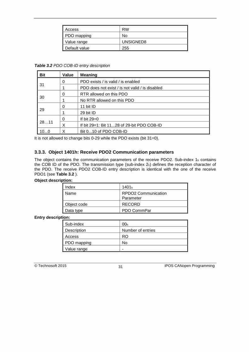
Access RW PDO mapping No Value range UNSIGNED8 Default value 255
Table 3.2 PDO COB-ID entry description
Bit Value Meaning
31 0 PDO exists / is valid / is enabled 1 PDO does not exist / is not valid / is disabled
30 0 RTR allowed on this PDO 1 No RTR allowed on this PDO
29 0 11 bit ID 1 29 bit ID
28…11 0 If bit 29=0 X If bit 29=1: Bit 11...28 of 29-bit PDO COB-ID
10...0 X Bit 0...10 of PDO COB-ID It is not allowed to change bits 0-29 while the PDO exists (bit 31=0).
3.3.3. Object 1401h: Receive PDO2 Communication parameters The object contains the communication parameters of the receive PDO2. Sub-index 1h contains the COB ID of the PDO. The transmission type (sub-index 2h) defines the reception character of the PDO. The receive PDO2 COB-ID entry description is identical with the one of the receive PDO1 (see Table 3.2 ). Object description:
Index 1401h Name RPDO2 Communication
Parameter Object code RECORD Data type PDO CommPar
Entry description: Sub-index 00h Description Number of entries Access RO PDO mapping No Value range -
© Technosoft 2015 iPOS CANopen Programming 31

Default value 2
Sub-index 01h
Description COB-ID RPDO2 Access RW PDO mapping No Value range UNSIGNED32 Default value 300h + Node-ID
Sub-index 02h
Description Transmission type Access RW PDO mapping No Value range UNSIGNED8 Default value 255
3.3.4. Object 1402h: Receive PDO3 Communication parameters The object contains the communication parameters of the receive PDO3. Sub-index 1h contains the COB ID of the PDO. The transmission type (sub-index 2h) defines the reception character of the PDO. The receive PDO3 COB-ID entry description is identical with the one of the receive PDO1 (see Table 3.2 ). Object description:
Index 1402h Name RPDO3 Communication
Parameter Object code RECORD Data type PDO CommPar
Entry description: Sub-index 00h Description Number of entries Access RO PDO mapping No Value range - Default value 2
Sub-index 01h
© Technosoft 2015 iPOS CANopen Programming 32

Description COB-ID RPDO3 Access RW PDO mapping No Value range UNSIGNED32 Default value 400h + Node-ID
Sub-index 02h
Description Transmission type Access RW PDO mapping No Value range UNSIGNED8 Default value 255
3.3.5. Object 1403h: Receive PDO4 Communication parameters The object contains the communication parameters of the receive PDO4. Sub-index 1h contains the COB ID of the PDO. The transmission type (sub-index 2h) defines the reception character of the PDO. The receive PDO4 COB-ID entry description is identical with the one of the receive PDO1 (see Table 3.2 ). Object description:
Index 1403h Name RPDO4 Communication
Parameter Object code RECORD Data type PDO CommPar
Entry description: Sub-index 00h Description Number of entries Access RO PDO mapping No Value range - Default value 2
Sub-index 01h
Description COB-ID RPDO2 Access RW PDO mapping No
© Technosoft 2015 iPOS CANopen Programming 33

Value range UNSIGNED32 Default value 500h + Node-ID
Sub-index 02h
Description Transmission type Access RW PDO mapping No Value range UNSIGNED8 Default value 255
3.3.6. Object 1600h: Receive PDO1 Mapping Parameters This object contains the mapping parameters of the receive PDO1. The sub-index 00h contains the number of valid entries within the mapping record. This number of entries is also the number of the objects that shall be transmitted/received with the corresponding PDO. The sub-indices from 01h to the number of entries contain the information about the mapped objects. These entries describe the PDO contents by their index, sub-index and length. The length entry contains the length of the mapped object in bits and is used to verify the overall mapping length. The structure of the entries from sub-index 01h to the number of entries is as follows: MSB LSB
Index (16 bits) Sub-index (8 bits) Object length (8 bits) In order to change the PDO mapping, first the PDO has to be disabled - the object 160xh sub-index 00h has to be set to 0. Now the objects can be remapped. If a wrong mapping parameter is introduced (object does not exist, the object cannot be mapped or wrong mapping length is detected) the SDO transfer will be aborted with an appropriate error code (0602 0000h or 0604 0041h). After all objects are mapped, sub-index 00h has to be set to the valid number of mapped objects thus enabling the PDO. If data types (index 01h - 07h) are mapped, they serve as “dummy entries”. The corresponding data is not evaluated by the drive. This feature can be used to transmit data to several drives using only one PDO, each drive using only a part of the PDO. This feature is only valid for receive PDOs. Object description:
Index 1600h Name RPDO1 Mapping Parameters Object code RECORD Data type PDO Mapping
Entry description: Sub-index 00h
© Technosoft 2015 iPOS CANopen Programming 34

Description Number of mapped objects Access RW PDO mapping No Value range 0: Mapping disabled
1 – 64: Sub-index 1 to x is valid Default value 1
Sub-index 01h
Description 1st mapped object Access RW PDO mapping No Value range UNSIGNED32 Default value 60400010h – control word
3.3.7. Object 1601h: Receive PDO2 Mapping Parameters This object contains the mapping parameters of the receive PDO2. The sub-index 00h contains the number of valid entries within the mapping record. This number of entries is also the number of the objects that shall be transmitted/received with the corresponding PDO. Object description:
Index 1601h Name RPDO2 Mapping Parameter Object code RECORD Data type PDO Mapping
Entry description: Sub-index 00h Description Number of mapped objects Access RW PDO mapping No Value range 0: Mapping disabled
1 – 64: Sub-index 1 to x is valid Default value 2
Sub-index 01h
Description 1st mapped object Access RW PDO mapping No
© Technosoft 2015 iPOS CANopen Programming 35

Value range UNSIGNED32 Default value 60400010h – control word
Sub-index 02h
Description 2nd mapped object Access RW PDO mapping No Value range UNSIGNED32 Default value 60600008h – modes of operation
3.3.8. Object 1602h: Receive PDO3 Mapping Parameters This object contains the mapping parameters of the receive PDO3. The sub-index 00h contains the number of valid entries within the mapping record. This number of entries is also the number of the objects that shall be transmitted/received with the corresponding PDO. Object description:
Index 1602h Name RPDO3 Mapping Parameter Object code RECORD Data type PDO Mapping
Entry description: Sub-index 00h Description Number of mapped objects Access RW PDO mapping No Value range 0: Mapping disabled
1 – 64: Sub-index 1 to x is valid Default value 2
Sub-index 01h
Description 1st mapped object Access RW PDO mapping No Value range UNSIGNED32 Default value 60400010h – control word
Sub-index 02h
© Technosoft 2015 iPOS CANopen Programming 36
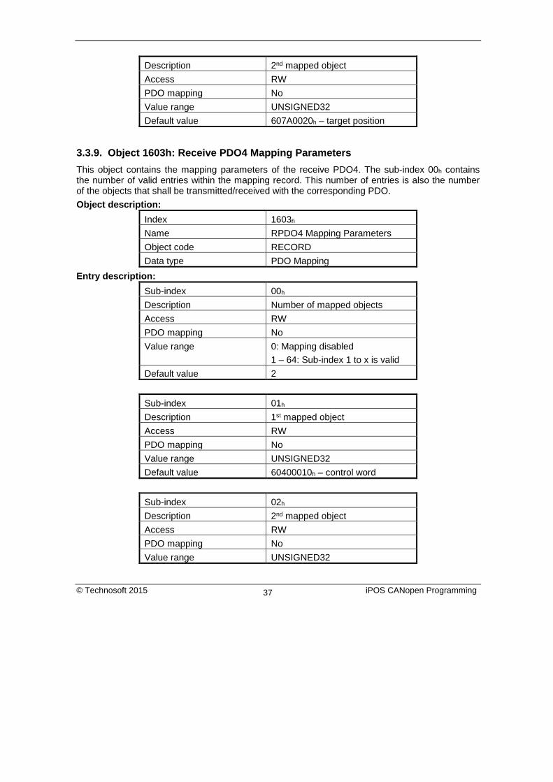
Description 2nd mapped object Access RW PDO mapping No Value range UNSIGNED32 Default value 607A0020h – target position
3.3.9. Object 1603h: Receive PDO4 Mapping Parameters This object contains the mapping parameters of the receive PDO4. The sub-index 00h contains the number of valid entries within the mapping record. This number of entries is also the number of the objects that shall be transmitted/received with the corresponding PDO. Object description:
Index 1603h Name RPDO4 Mapping Parameters Object code RECORD Data type PDO Mapping
Entry description: Sub-index 00h Description Number of mapped objects Access RW PDO mapping No Value range 0: Mapping disabled
1 – 64: Sub-index 1 to x is valid Default value 2
Sub-index 01h
Description 1st mapped object Access RW PDO mapping No Value range UNSIGNED32 Default value 60400010h – control word
Sub-index 02h
Description 2nd mapped object Access RW PDO mapping No Value range UNSIGNED32
© Technosoft 2015 iPOS CANopen Programming 37
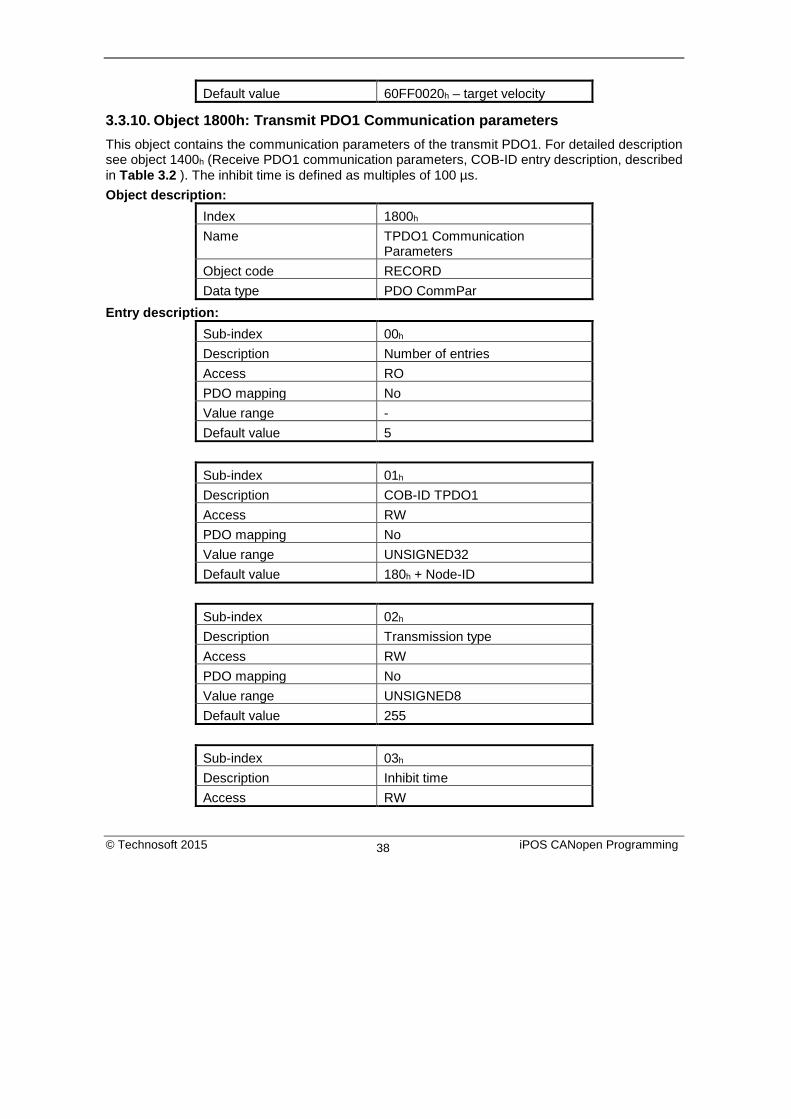
Default value 60FF0020h – target velocity
3.3.10. Object 1800h: Transmit PDO1 Communication parameters This object contains the communication parameters of the transmit PDO1. For detailed description see object 1400h (Receive PDO1 communication parameters, COB-ID entry description, described in Table 3.2 ). The inhibit time is defined as multiples of 100 µs. Object description:
Index 1800h Name TPDO1 Communication
Parameters Object code RECORD Data type PDO CommPar
Entry description: Sub-index 00h Description Number of entries Access RO PDO mapping No Value range - Default value 5
Sub-index 01h
Description COB-ID TPDO1 Access RW PDO mapping No Value range UNSIGNED32 Default value 180h + Node-ID
Sub-index 02h
Description Transmission type Access RW PDO mapping No Value range UNSIGNED8 Default value 255
Sub-index 03h
Description Inhibit time Access RW
© Technosoft 2015 iPOS CANopen Programming 38

PDO mapping No Value range UNSIGNED16 Default value 300 (30 ms)
Sub-index 04h
Description Reserved
Sub-index 05h
Description Event timer Access RW PDO mapping No Value range UNSIGNED16 Default value 0
3.3.11. Object 1801h: Transmit PDO2 Communication parameters This object contains the communication parameters of the transmit PDO2. For detailed description see object 1400h (Receive PDO1 communication parameters, COB-ID entry description, described in Table 3.2 ). The inhibit time is defined as multiples of 100 µs. Object description:
Index 1801h Name TPDO2 Communication
Parameters Object code RECORD Data type PDO CommPar
Entry description: Sub-index 00h Description Number of entries Access RO PDO mapping No Value range - Default value 5
Sub-index 01h
Description COB-ID TPDO2 Access RW PDO mapping No
© Technosoft 2015 iPOS CANopen Programming 39

Value range UNSIGNED32 Default value 280h + Node-ID
Sub-index 02h
Description Transmission type Access RW PDO mapping No Value range UNSIGNED8 Default value 255
Sub-index 03h
Description Inhibit time Access RW PDO mapping No Value range UNSIGNED16 Default value 300 (30 ms)
Sub-index 04h
Description Reserved
Sub-index 05h
Description Event timer Access RW PDO mapping No Value range UNSIGNED16 Default value 0
3.3.12. Object 1802h: Transmit PDO3 Communication parameters This object contains the communication parameters of the transmit PDO3. By default, this TxPDO is disabled by setting Bit31 to 1b in Sub-index 01h. For detailed description see object 1400h (Receive PDO1 communication parameters, COB-ID entry description, described in Table 3.2 ). The inhibit time is defined as multiples of 100 µs. Object description:
Index 1802h Name TPDO3 Communication
Parameters
© Technosoft 2015 iPOS CANopen Programming 40

Object code RECORD Data type PDO CommPar
Entry description:
Sub-index 00h Description Number of entries Access RO PDO mapping No Value range - Default value 5
Sub-index 01h
Description COB-ID TPDO3 Access RW PDO mapping No Value range UNSIGNED32 Default value 80000380h + Node-ID
Sub-index 02h
Description Transmission type Access RW PDO mapping No Value range UNSIGNED8 Default value 255
Sub-index 03h
Description Inhibit time Access RW PDO mapping No Value range UNSIGNED16 Default value 300 (30 ms)
Sub-index 04h
Description Reserved
Sub-index 05h
© Technosoft 2015 iPOS CANopen Programming 41

Description Event timer Access RW PDO mapping No Value range UNSIGNED16 Default value 0
3.3.13. Object 1803h: Transmit PDO4 Communication parameters This object contains the communication parameters of the transmit PDO4. By default, this TxPDO is disabled by setting Bit31 to 1b in Sub-index 01h. For detailed description see object 1400h (Receive PDO1 communication parameters, COB-ID entry description, described in Table 3.2 ) . The inhibit time is defined as multiples of 100 µs. Object description:
Index 1803h Name TPDO4 Communication
Parameter Object code RECORD Data type PDO CommPar
Entry description: Sub-index 00h Description Number of entries Access RO PDO mapping No Value range - Default value 5
Sub-index 01h
Description COB-ID TPDO4 Access RW PDO mapping No Value range UNSIGNED32 Default value 80000480h + Node-ID
Sub-index 02h
Description Transmission type Access RW PDO mapping No
© Technosoft 2015 iPOS CANopen Programming 42

Value range UNSIGNED8 Default value 255
Sub-index 03h
Description Inhibit time Access RW PDO mapping No Value range UNSIGNED16 Default value 300 (30 ms)
Sub-index 04h
Description Reserved
Sub-index 05h
Description Event timer Access RW PDO mapping No Value range UNSIGNED16 Default value 0
3.3.14. Object 1A00h: Transmit PDO1 Mapping Parameters This object contains the mapping parameters of the transmit PDO1. For detailed description see object 1600h (Receive PDO1 mapping parameters) Object description:
Index 1A00h Name TPDO1 Mapping Parameters Object code RECORD Data type PDO Mapping
Entry description: Sub-index 00h Description Number of mapped objects Access RW PDO mapping No Value range 0: Mapping disabled
1 – 64: Sub-index 1 to x is valid Default value 1
© Technosoft 2015 iPOS CANopen Programming 43

Sub-index 01h
Description 1st mapped object Access RW PDO mapping No Value range UNSIGNED32 Default value 60410010h – status word
3.3.15. Object 1A01h: Transmit PDO2 Mapping Parameters This object contains the mapping parameters of the transmit PDO2. For detailed description see object 1600h (Receive PDO1 mapping parameters) Object description:
Index 1A01h Name TPDO2 Mapping Parameter Object code RECORD Data type PDO Mapping
Entry description: Sub-index 00h Description Number of mapped objects Access RW PDO mapping No Value range 0: Mapping disabled
1 – 64: Sub-index 1 to x is valid Default value 2
Sub-index 01h
Description 1st mapped object Access RW PDO mapping No Value range UNSIGNED32 Default value 60410010h – status word
Sub-index 02h
Description 2nd mapped object Access RW PDO mapping No
© Technosoft 2015 iPOS CANopen Programming 44

Value range UNSIGNED32 Default value 60610008h – modes of operation
display
3.3.16. Object 1A02h: Transmit PDO3 Mapping Parameters This object contains the mapping parameters of the transmit PDO3. For detailed description see object 1600h (Receive PDO1 mapping parameters). By default, this PDO is disabled with object 1802h Sub-index 01 by setting Bit31 to 1. Object description:
Index 1A02h Name TPDO3 Mapping Parameter Object code RECORD Data type PDO Mapping
Entry description: Sub-index 00h Description Number of entries Access RW PDO mapping No Value range 0: Mapping disabled
1 – 64: Sub-index 1 to x is valid Default value 2
Sub-index 01h
Description 1st mapped object Access RW PDO mapping No Value range UNSIGNED32 Default value 60410010h – status word
Sub-index 02h
Description 2nd mapped object Access RW PDO mapping No Value range UNSIGNED32 Default value 60640020h – position actual value
© Technosoft 2015 iPOS CANopen Programming 45

3.3.17. Object 1A03h: Transmit PDO4 Mapping Parameters This object contains the mapping parameters of the transmit PDO4. For detailed description see object 1600h (Receive PDO1 mapping parameters). By default, this PDO is disabled with object 1803h Sub-index 01 by setting Bit31 to 1. Object description:
Index 1A03h Name TPDO4 Mapping Parameter Object code RECORD Data type PDO Mapping
Entry description: Sub-index 00h Description Number of entries Access RW PDO mapping No Value range 0: Mapping disabled
1 – 64: Sub-index 1 to x is valid Default value 2
Sub-index 01h
Description 1st mapped object Access RW PDO mapping No Value range UNSIGNED32 Default value 60410010h – status word
Sub-index 02h
Description 2nd mapped object Access RW PDO mapping No Value range UNSIGNED32 Default value 606C0020h – velocity actual value
© Technosoft 2015 iPOS CANopen Programming 46
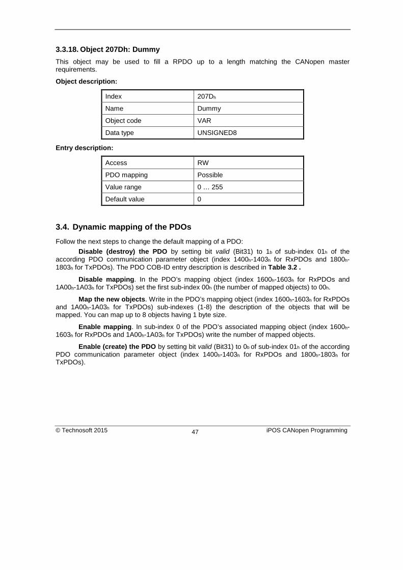
3.3.18. Object 207Dh: Dummy This object may be used to fill a RPDO up to a length matching the CANopen master requirements.
Object description:
Index 207Dh
Name Dummy
Object code VAR
Data type UNSIGNED8
Entry description:
Access RW
PDO mapping Possible
Value range 0 … 255
Default value 0
3.4. Dynamic mapping of the PDOs Follow the next steps to change the default mapping of a PDO: Disable (destroy) the PDO by setting bit valid (Bit31) to 1b of sub-index 01h of the according PDO communication parameter object (index 1400h-1403h for RxPDOs and 1800h-1803h for TxPDOs). The PDO COB-ID entry description is described in Table 3.2 .
Disable mapping. In the PDO’s mapping object (index 1600h-1603h for RxPDOs and 1A00h-1A03h for TxPDOs) set the first sub-index 00h (the number of mapped objects) to 00h.
Map the new objects. Write in the PDO’s mapping object (index 1600h-1603h for RxPDOs and 1A00h-1A03h for TxPDOs) sub-indexes (1-8) the description of the objects that will be mapped. You can map up to 8 objects having 1 byte size.
Enable mapping. In sub-index 0 of the PDO’s associated mapping object (index 1600h-1603h for RxPDOs and 1A00h-1A03h for TxPDOs) write the number of mapped objects.
Enable (create) the PDO by setting bit valid (Bit31) to 0b of sub-index 01h of the according PDO communication parameter object (index 1400h-1403h for RxPDOs and 1800h-1803h for TxPDOs).
© Technosoft 2015 iPOS CANopen Programming 47

3.5. RxPDOs mapping example
Map the Receive PDO3 of axis number 06 with ControlWord (index 6040h) and Modes of Operation (index 6060h).
1. Disable the RxPDO. Set Bit31 to 1b of sub-index 01h in object 1402h, this will disable the RxPDO. The PDO COB-ID entry description is described in Table 3.2 .
Bit31
valid RxPDO3 COB-ID
Axis Node ID
Resulting data
0b + 400h + 06h = 80000406h
Send the following message (SDO access to object 1402h sub-index 1, 32-bit value 80000406h):
COB-ID 606
Data 23 02 14 01 06 04 00 80
2. Change the communication parameters. For example purposes the communication parameters default values are acceptable.
3. Disable mapping PDO. Write zero in object 1602h sub-index 0, this will the PDO’s mapping.
Send the following message (SDO access to object 1602h sub-index 0, 8-bit value 0):
COB-ID 606
Data 2F 02 16 00 00 00 00 00
4. Map the new objects. a. Write in object 1602h sub-index 1 the description of the Control Word:
Index Sub-index Length Resulting data
6040h 00h 10h 60400010h
Send the following message (SDO access to object 1602h sub-index 1, 32-bit value 60400010h):
COB-ID 606
Data 23 02 16 01 10 00 40 60 b. Write in object 1602h sub-index 2 the description of the Modes of Operation:
Index Sub-index Length Resulting data
6060h 00h 08h 60600008h
Send the following message (SDO access to object 1602h sub-index 2, 32-bit value 60600008h):
© Technosoft 2015 iPOS CANopen Programming 48

COB-ID 606
Data 23 02 16 02 08 00 60 60
5. Enable the RxPDO’s mapped objects. Set the object 1602h sub-index 0 with the value 2 to enable both mapped objects.
Send the following message (SDO access to object 1602h sub-index 0, 8-bit value 2):
COB-ID 606
Data 2F 02 16 00 02 00 00 00 6. Enable the RxPDO. Set Bit31 to 0b of sub-index 01h in object 1402h, this will enable the
RxPDO. Set in object 1402h sub-index 1 Bit31 to 0. The PDO COB-ID entry description is described in Table 3.2 .
Bit31
valid RxPDO3 COB-ID
Axis Node ID
Resulting data
0b + 400h + 06h = 00000406h
Send the following message (SDO access to object 1402h sub-index 1, 32-bit value 0x00000406):
COB-ID 606
Data 23 02 14 01 06 04 00 00
3.6. TxPDOs mapping example
Map the Transmit PDO4 of axis number 06 with Position actual value (index 6064h) and Digital inputs (index 60FDh). Disable the TxPDO. Set Bit31 to 1b of sub-index 01h in object 1803h, this will disable the TxPDO. The PDO COB-ID entry description is described in Table 3.2 .
Bit31
valid TxPDO4 COB-ID
Axis Node ID
Resulting data
0b + 480h + 06h = 80000486h
Send the following message (SDO access to object 1801h sub-index 1, 32-bit value 80000486h):
COB-ID 606
Data 23 03 18 01 86 04 00 80
© Technosoft 2015 iPOS CANopen Programming 49
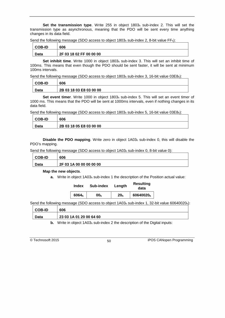
Set the transmission type. Write 255 in object 1803h sub-index 2. This will set the transmission type as asynchronous, meaning that the PDO will be sent every time anything changes in its data field.
Send the following message (SDO access to object 1803h sub-index 2, 8-bit value FFh):
COB-ID 606
Data 2F 03 18 02 FF 00 00 00
Set inhibit time. Write 1000 in object 1803h sub-index 3. This will set an inhibit time of 100ms. This means that even though the PDO should be sent faster, it will be sent at minimum 100ms intervals.
Send the following message (SDO access to object 1803h sub-index 3, 16-bit value 03E8h):
COB-ID 606
Data 2B 03 18 03 E8 03 00 00
Set event timer. Write 1000 in object 1803h sub-index 5. This will set an event timer of 1000 ms. This means that the PDO will be sent at 1000ms intervals, even if nothing changes in its data field.
Send the following message (SDO access to object 1803h sub-index 5, 16-bit value 03E8h):
COB-ID 606
Data 2B 03 18 05 E8 03 00 00
Disable the PDO mapping. Write zero in object 1A03h sub-index 0, this will disable the PDO’s mapping.
Send the following message (SDO access to object 1A03h sub-index 0, 8-bit value 0):
COB-ID 606
Data 2F 03 1A 00 00 00 00 00
Map the new objects. a. Write in object 1A03h sub-index 1 the description of the Position actual value:
Index Sub-index Length Resulting data
6064h 00h 20h 60640020h
Send the following message (SDO access to object 1A03h sub-index 1, 32-bit value 60640020h):
COB-ID 606
Data 23 03 1A 01 20 00 64 60 b. Write in object 1A03h sub-index 2 the description of the Digital inputs:
© Technosoft 2015 iPOS CANopen Programming 50

Index Sub-index Length Resulting data
60FDh 00h 20h 60FD0020h
Send the following message (SDO access to object 1A03h sub-index 2, 32-bit value 60FD0020h):
COB-ID 606
Data 23 03 1A 02 20 00 FD 60
Enable the TxPDO’s mapped objects. Set the object 1A03h sub-index 0 with the value 2 to enable both mapped objects.
Send the following message (SDO access to object 1A03h sub-index 0, 8-bit value 2):
COB-ID 606
Data 2F 03 1A 00 02 00 00 00 Enable the TxPDO 4. Set Bit31 to 0b of sub-index 01h in object 1803h, this will enable the TxPDO 4. Set in object 1803h sub-index 1 Bit31 to 0. The PDO COB-ID entry description is described in Table 3.2 .
Bit31
valid TxPDO4 COB-ID
Axis Node ID
Resulting data
0b + 480h + 06h = 00000486h
Send the following message (SDO access to object 1803h sub-index 1, 32-bit value 0x00000486):
COB-ID 606
Data 23 03 18 01 86 04 00 00
Start remote node 6. Send a NMT message to start the node id 6. This message is to enable the use of the PDOs.
Send the following message:
COB-ID 0
Data 01 06 After the last message, the drive will start emitting at 1s intervals data with COB-ID 0x486 showing the motor actual position and the Digital input status. If the encoder is rotated, the PDO will be sent every time the position changes, but not faster than 100ms.
© Technosoft 2015 iPOS CANopen Programming 51

4. Network Management
4.1. Overview The Network Management (NMT) services initialize, start, monitor, reset or stop the CANopen nodes. The NMT requires a node in the network (a PC or a PLC) to be designed as a network manager while the Technosoft intelligent drives are the NMT slaves. The NMT services are fulfilled by the NMT objects described later in this chapter.
4.1.1. Network Management (NMT) State Machine Figure 4.1.1 shows the NMT state diagram of a CANopen device. After finishing the initialization, the iPOS drive enters the NMT state Pre-operational. During this state, both the communication parameters and drive parameters can be changed using SDO messages. In this state the PDO messages are defined. Once entered in the operational mode, the drive is typically controlled via PDO messages.
Figure 4.1 NMT state diagram
© Technosoft 2015 iPOS CANopen Programming 52

Table 4.1 NMT state transitions
(1) At Power on the NMT state initialization is entered autonomously (2) NMT state initialization finished - enter NMT state Pre-
operational automatically
(3) NMT service start remote node indication or by local control
(4),(7) NMT service enter pre-operational indication
(5),(8) NMT service stop remote node indication
(6) NMT service start remote node indication
(9),(10),(11) NMT service reset node indication
(12),(13),(14) NMT service reset communication indication
4.1.2. Device control
Through Module Control Services, the NMT master controls the state of the NMT slaves. The following states are implemented on the Technosoft drives:
State Description
Pre-operational The drive enters the pre-operational state after finishing its initialization. In this state the communication between the CANopen master and the drive can be done only via SDOs. PDOs are not allowed.
Operational This is the normal operating state of the drives. The communication through SDO and PDO is allowed
Stopped In this state the drive stops the communication except the network management messages.
The network manager can change the state of the drives using one of the following services:
Service Description
Start
Remote Node The NMT master sets the state of the selected NMT slave to operational
Stop
Remote Node The NMT master sets the state of the selected NMT slave to stopped
Enter
Pre-Operational The NMT master sets the state of the selected NMT slave to pre-operational
© Technosoft 2015 iPOS CANopen Programming 53

Reset Node The NMT master sets the state of the selected NMT slave to the “reset application” sub-state. In this state the drives perform a software reset and enter the pre-operational state.
Reset Communication
The NMT master sets the state of the selected NMT slave to the “reset communication” sub-state. In this state the drives resets their communication and enter the pre-operational state.
All the services are unconfirmed.
4.1.2.1. Enter Pre-Operational Used to change NMT state of one or all NMT slaves to “Pre-Operational”.
cs 0x80 Command specifier for NMT command Enter Pre-Operational Node ID
1…127
NMT slave with corresponding Node ID will enter in NMT state Pre-Operational
0 All NMT Slaves will enter NMT state Pre-Operational
Figure 4.2 NMT Enter Pre-Operational
4.1.2.2. Reset communication Used to reset communication of one or all NMT slaves.
cs 0x82 Command specifier for NMT command Reset Communication Node ID
1…127 NMT slave with corresponding Node ID will reset communication
0 All NMT Slaves will reset communication
Figure 4.3 NMT Reset Communication
4.1.2.3. Reset Node Used to reset one or all NMT slaves.
cs 0x81 Command specifier for NMT command Reset Node
© Technosoft 2015 iPOS CANopen Programming 54

Node ID
1…127 NMT slave with corresponding Node ID will reset
0 All NMT Slaves will reset
Figure 4.4 NMT Reset Node
4.1.2.4. Start Remote Node Used to change NMT state of one or all NMT slaves to “Operational”. PDO communication will be allowed.
cs 0x01 Command specifier for NMT command Start Remote Node Node ID
1…127 NMT slave with corresponding Node ID will enter “Operational” state
0 All NMT Slaves will enter “Operational” state
Figure 4.5 NMT Start Remote Node
4.1.2.5. Stop Remote Node Used to change NMT state of one or all NMT slaves to “Stopped”.
cs 0x02 Command specifier for NMT command Stop Remote Node Node ID
1…127 NMT slave with corresponding Node ID will enter “Stopped” state
0 All NMT Slaves will enter “Stopped” state
Figure 4.6 NMT Stop Remote Node
© Technosoft 2015 iPOS CANopen Programming 55

4.1.3. Device monitoring In addition to controlling the drive states the NMT provides services for monitoring the nodes in the network. The monitoring services are achieved mainly through the periodical transmission of messages by the network manager, with answers from the slaves, or messages sent by the slaves without master intervention. Monitoring services can use the Node Guarding protocol (including Life Guarding) or the Heartbeat protocol.
4.1.3.1. Node guarding protocol The master polls each NMT slave at regular time intervals. This time interval is called the guard time and may be different for each NMT slave. The slaves answer with a node-guarding message containing their state. This allows both the master and the slave to identify a network error if either the remote request or the guarding messages stop. The node life time is computed as the product between the guard time (index 100Ch) and the life time factor (index 100Dh). If the drive is not accessed within the life time then a Life Time event occurs and an emergency telegram is sent.
4.1.3.2. Heartbeat protocol The Heartbeat protocol defines an error control service without the need of remote frames. It implies independent and cyclical transmission of a telegram by the drive (the Heartbeat producer) indicating the drives current state. The time interval between two heartbeat messages is specified through producer heartbeat time (index 1017h). The master (Heartbeat consumer) guards the reception of the heartbeat messages within the Heartbeat Consumer Time. If the value of this object is 0, the heartbeat transmission is disabled. If the master doesn’t receive the heartbeat message this indicates a problem with the drive or with its network connection.
4.1.3.3. Bootup protocol This protocol is used by the drive to signal to the network master that it has entered the state pre-operational. When the drive is powered on for the time or is reset, it will send a bootup message with the COB-ID (0x700+ Node Id) and Data 00.
4.1.4. Synchronization between devices The synchronization message (SYNC with COB ID 0x80 and no Data) allows synchronizing the devices in the network and triggering the synchronous transmission of PDOs. The SYNC producer broadcasts the synchronization message periodically. This service is unconfirmed. Technosoft intelligent drives can act both as SYNC consumer and producer. There are two ways to synchronize the drive in a network: 1. Send only the sync message with the COB ID 0x80 and Data null at very precise intervals. This method is the most commonly used and its accuracy is based on how precise the master sends the SYNCS and the CAN bus load 2.For time critical applications, which require more accurate synchronization, the Technosoft drives can use the optional high-resolution synchronization protocol, which employs a special form of time stamp message. The High Resolution Time Stamp can be set with the COB ID 0x100 and 4 bytes of data that represent a time stamp with a resolution of 1µs. When the master sends a time stamp with the COB ID 0x100 it has the same effect as writing the same value to all the
© Technosoft 2015 iPOS CANopen Programming 56

slaves in the network in object 1013 h. In this second method, the master sends the sync message (0x80) followed immediately by the time stamp message with the id 0x100. When one of the Technosoft drives is set as synchronization master, the High resolution time stamp is by default sent using the COB ID defined in COB-ID High Resolution Time Stamp object (index 2004h).
4.1.5. Emergency messages A drive sends an emergency message (EMCY) when a drive internal error occurs. An emergency message is transmitted only once per ‘error event’. As long as no new errors occur, the drive will not transmit further emergency messages. The emergency error codes supported by the Technosoft drives are listed in Table 4.2. Details regarding the conditions that may generate emergency messages are presented at object Motion Error Register index 2000h.
Table 4.2 Emergency Error Codes
Error code (hex) Description
0000 Error Reset or No Error
1000 Generic Error
2310 Continuous over-current
2340 Short-circuit
3210 DC-link over-voltage
3220 DC-link under-voltage
4280 Over temperature motor
4310 Over temperature drive
5441 Drive disabled due to enable input
5442 Negative limit switch active
5443 Positive limit switch active
6100 Invalid setup data
7500 Communication error
8110 CAN overrun (message lost)
8130 Life guard error or heartbeat error
8331 I2t protection triggered
8580 Position wraparound
8611 Control error / Following error
© Technosoft 2015 iPOS CANopen Programming 57

9000 Command error
FF01 Generic interpolated position mode error (PVT / PT error)
FF02 Change set acknowledge bit wrong value
FF03 Specified homing method not available
FF04 A wrong mode is set in object 6060h, modes_of_operation
FF05 Specified digital I/O line not available
FF06 Positive software position limit triggered
FF07 Negative software position limit triggered
FF08 Enable circuit hardware error
The Emergency message contains of 8 data bytes having the following contents:
0-1 2 3-7
Emergency Error Code Error Register (Object 1001h) Manufacturer specific error field
4.2. Network management objects The section describes the objects related to network management
4.2.1. Object 1001h: Error Register This object is an error register for the device. The device can map internal errors in this byte. This entry is mandatory for all devices. It is a part of an Emergency object. Object description:
Index 1001h Name Error register Object code VAR Data type UNSIGNED8
Entry description: Access RO PDO mapping No Value range UNSIGNED8 Default value No
© Technosoft 2015 iPOS CANopen Programming 58

Table 4.3 Bit description of the object
Bit Description 0 Generic error
1 Current
2 Voltage
3 Temperature
4 Communication error
5 Device profile specific
6 Reserved (always 0)
7 Manufacturer specific.
Valid bits while an error occurs – bit 0 and bit 4. The other bits will remain 0.
4.2.2. Object 1003h: Pre-defined error field This object provides the errors that occurred on the iPOS drive and were signaled via the emergency object. If no error was signaled, sub-index 00h reports 0 entries. The object can report up to 5 emergency messages recently transmitted. The last reported error will always be set in sub-index 1. Object description:
Index 1003h Name Pre-defined error field Object code ARRAY Data type UNSIGNED32
Entry description: Sub-index 00h Description Number of errors in history Access RO PDO mapping No Value range 1..5 Default value 0
Sub-index 01h
Description Standard error field Access RO PDO mapping No Value range UNSIGNED32
© Technosoft 2015 iPOS CANopen Programming 59

Default value -
Sub-index 02h to 05h
Description Standard error field Access RO PDO mapping No Value range UNSIGNED32 Default value -
4.2.3. Object 1005h: COB-ID of the SYNC Message This object defines the COB-ID of the Synchronization Object (SYNC) and whether the drive generates the SYNC or not. Object description:
Index 1005h Name COB-ID SYNC Message Object code VAR Data type UNSIGNED32
Entry description: Access RW PDO mapping No Value range UNSIGNED32 Default value 80h
The structure of the parameter is the following:
Table 4.4 Bit description of the object
Bit Value Description 31 X Reserved
30 0 Drive does not generate synchronization messages 1 Drive is the synchronization master (SYNC producer)
29 0 Use 11 bit identifier 1 Use 29 bit identifier
28…11 X Bit 11...28 of 29-bit SYNC COB-ID 10...0 X Bit 0...10 of SYNC COB-ID
© Technosoft 2015 iPOS CANopen Programming 60
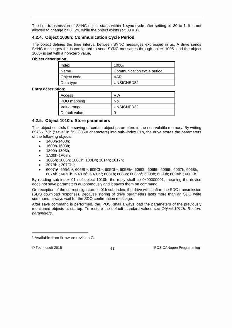
The first transmission of SYNC object starts within 1 sync cycle after setting bit 30 to 1. It is not allowed to change bit 0...29, while the object exists (bit 30 = 1).
4.2.4. Object 1006h: Communication Cycle Period The object defines the time interval between SYNC messages expressed in μs. A drive sends SYNC messages if it is configured to send SYNC messages through object 1005h and the object 1006h is set with a non-zero value. Object description:
Index 1006h Name Communication cycle period Object code VAR Data type UNSIGNED32
Entry description: Access RW PDO mapping No Value range UNSIGNED32 Default value 0
4.2.5. Object 1010h: Store parameters This object controls the saving of certain object parameters in the non-volatile memory. By writing 65766173h (“save” in /ISO8859/ characters) into sub--index 01h, the drive stores the parameters of the following objects:
• 1400h-1403h; • 1600h-1603h; • 1800h-1803h; • 1A00h-1A03h; • 1005h; 1006h; 100Ch; 100Dh; 1014h; 1017h; • 207Bh1; 207Ch1; • 6007h1; 605Ah1; 605Bh1; 605Ch1; 605Dh1; 605Eh1; 6060h; 6065h; 6066h; 6067h; 6068h;
607Ah1; 607Ch; 607Dh1; 607Eh1; 6081h; 6083h; 6085h1; 6098h; 6099h; 609Ah1; 60FFh. By reading sub-index 01h of object 1010h, the reply shall be 0x00000001, meaning the device does not save parameters autonomously and it saves them on command. On reception of the correct signature in 01h sub-index, the drive will confirm the SDO transmission (SDO download response). Because storing of drive parameters lasts more than an SDO write command, always wait for the SDO confirmation message. After save command is performed, the iPOS, shall always load the parameters of the previously mentioned objects at startup. To restore the default standard values see Object 1011h: Restore parameters.
1 Available from firmware revision G.
© Technosoft 2015 iPOS CANopen Programming 61

Object description: Index 1010h Name Store parameters Object code ARRAY Data type UNSIGNED32
Entry description: Sub-index 00h Description highest sub-index supported Access RO PDO mapping No Value range 1 Default value 1
Sub-index 01h
Description Save parameters Access RW PDO mapping No Value range UNSIGNED32 Default value -
To save the parameters of the objects previously mentioned, send the following command:
(SDO access to object 1010h sub-index 1, 32-bit value 65766173h)
COB-ID 60A
Data 23 10 10 01 73 61 76 65
4.2.6. Object 1011h: Restore parameters This object restores certain object parameters to their default values. By writing 64616F6Ch (“load” in /ISO8859/ characters) into sub--index 01h, the drive restores to their default values the parameters of the following objects :
• 1400h-1403h; • 1600h-1603h; • 1800h-1803h; • 1A00h-1A03h; • 1005h; 1006h; 100Ch; 100Dh; 1014h; 1017h; • 6065h; 6066h; 6067h; 6068h; 6060h; 607Ch; 6081h; 6083h; 6098h; 6099h; 60FFh
By reading sub-index 01h of object 1011h, the reply shall be 0x00000001, meaning the device can restore CANopen parameters to their default value. The default values will be set valid after the iPOS drive is reset.
© Technosoft 2015 iPOS CANopen Programming 62

Object description: Index 1011h Name Restore default parameters Object code ARRAY Data type UNSIGNED32
Entry description: Sub-index 00h Description highest sub-index supported Access RO PDO mapping No Value range 1 Default value 1
Sub-index 01h
Description Restore all default parameters Access RW PDO mapping No Value range UNSIGNED32 Default value -
To restore the object parameters to their default values, send the following command:
(SDO access to object 1011h sub-index 1, 32-bit value 64616F6C h)
COB-ID 60A
Data 23 11 10 01 6C 6F 61 64
4.2.7. Object 100Ch: Guard Time The Guard Time object multiplied with Lifetime Factor (index 100Dh) gives the Lifetime of the drive for the Life Guarding Protocol. The Guard Time is expressed in ms. When the Life Guarding Protocol is not used the object must be set to 0. When the Node Guarding is active, i.e. the network manager sends the Node Guarding messages, the Life Guarding Protocol checks if the master has stopped sending messages or not. The decision of Node Guarding failure is taken if no message from the master is received within the period defined as Lifetime. Object description:
Index 100Ch Name Guard time Object code VAR Data type UNSIGNED16
© Technosoft 2015 iPOS CANopen Programming 63

Entry description: Access RW PDO mapping No Value range UNSIGNED16 Default value 0
4.2.8. Object 100Dh: Life Time Factor The lifetime factor multiplied with the guard time gives the lifetime for the Life Guarding Protocol. Must be 0 if not used. Object description:
Index 100Dh Name Life time factor Object code VAR Data type UNSIGNED8
Entry description: Access RW PDO mapping No Value range UNSIGNED8 Default value 0
4.2.9. Object 1013h: High Resolution Time Stamp This object can receive a time stamp with a resolution of 1μs (1 unit = 1μs). It can be used in order to synchronize the drives in the CANopen network. When setting up the synchronization mechanism, the master can map the object 1013h on a receive PDO whose COB-ID should be identical on all the slave drives that need to be synchronized. This object has to be written immediately after the SYNC message (the one that has the COB-ID 0x80). Upon the time reception in this object, the drive will compensate for the difference between the received value and its internal clock value. The object also provides the drives internal clock value with a resolution of 1μs when read. It can be mapped to a TxPDO to transmit a precise time over the network. Remark 1: the drive internal clock will not be read anymore if a value is written into object 1013h. When object 1013h is read, it will give either the internal clock or the last value written in it. Remark 2: If a 4 byte (32bit) High Resolution Time Stamp is sent with the COB ID 0x100 right after the sync message(with ID 0x80), all the drives in the network will receive the time data as if it was received into object 1013h. Example: ID 0x100 Data 00 00 E8 03 – absolute time is 1000 (0x03E8) μs = 1ms.
© Technosoft 2015 iPOS CANopen Programming 64

Object description: Index 1013h Name High resolution time stamp Object code VAR Data type UNSIGNED32
Entry description: Access RW PDO mapping Possible Value range UNSIGNED32 Default value 0
4.2.10. Object 2004h: COB-ID of the High-resolution time stamp This object defines the COB-ID used by the high-resolution time stamp message sent by the synchronization master (when the drive is configured as a SYNC producer) in order to achieve synchronization on the network. When the drive is the SYNC producer, this object defines if the high resolution time stamp is sent or not. Object description:
Index 2004h Name COB-ID High resolution time
stamp Object code VAR Data type UNSIGNED32
Entry description: Access RW PDO mapping No Value range UNSIGNED32 Default value 100h
The structure of the parameter is the following: Bit Value Meaning
31 0 High resolution time stamp exists / is valid 1 High resolution time stamp does not exist / is not valid
30 0 Reserved (always 0)
29 0 11 bit ID 1 29 bit ID
28…11 X Bit 11...28 of 29-bit High resolution time stamp COB-ID 10...0 X Bit 0...10 of High resolution time stamp COB-ID
© Technosoft 2015 iPOS CANopen Programming 65

It is not allowed to change bits 0-29 while the object exists (bit 31=0). This object will be used when a Technosoft drive is required to be the master for the synchronization messages. In this case, the CANopen master does not need to map the 1013h into a receive PDO.
4.2.11. Configure the drive as a SYNC master Example The procedure to activate the synchronization is the following:
1. Set the SYNC interval. Write the desired SYNC interval into the object 1006h (Communication Cycle Period). For example – 20 ms.
Send the following message (SDO access to object 1006h sub-index 0, 32-bit value 0x4E20 = 20000 μs = 20 ms):
COB-ID 60A
Data 23 06 10 00 20 4E 00 00
2. Activate the SYNC producer. Set bit 30 in object 1005h (COB-ID of SYNC Message).
Send the following message (SDO access to object 1005h sub-index 0, 32-bit value 40000080h):
COB-ID 60A
Data 23 05 10 00 80 00 00 40 The drive will start sending sync messages with COB ID 0x80 Data null. It will also send time stamp messages with COB ID 0x100 Data 0x12 0x34 0x56 0x78 0x00 0x00 where 0x000078563412 is the time stamp data expressed in μs. Also, if in object 2004h the time stamp is disabled, the sync producer will emit only sync messages with COB ID 0x80.
4.2.12. Object 1014h: COB-ID Emergency Object Index 1014h defines the COB-ID of the Emergency Object (EMCY). Object description:
Index 1014h Name COB-ID Emergency message Object code VAR Data type UNSIGNED32
Entry description: Access RW PDO mapping No Value range UNSIGNED32 Default value 80h + Node-ID
© Technosoft 2015 iPOS CANopen Programming 66

Table 4.5 Structure of the EMCY Identifier
MSB LSB 31 30 29 28 - 11 10 - 0 0/1 0 1 0 0 0 0 0 0 0 0 0 0 0 0 0 0 0 0 0 0 11-bit Identifier 0/1 0 1 29 –bit Identifier
Table 4.6 Description of EMCY COB-ID entry
Bit Value Description 31 (MSB) 0 EMCY exists / is valid
1 EMCY does not exist / is not valid 30 0 Reserved
29 0 Use 11 bit identifier 1 Use 29 bit identifier
28…11 0 X
If bit 29 = 0 Bit 11...28 of 29-bit SYNC COB-ID
10...0 (LSB) X Bit 0...10 of COB-ID It is not allowed to change Bits 0-29, while the object exists (Bit 31=0).
© Technosoft 2015 iPOS CANopen Programming 67

4.2.13. Object 1017h: Producer Heartbeat Time This object defines the cycle time of the heartbeat (if not equal to zero). If the heartbeat is not used, this object must have the default value 0. The time has to be a multiple of 1 ms. Object description:
Index 1017h Name Producer Heartbeat Time Object code VAR Data type UNSIGNED16
Entry description: Access RW PDO mapping No Value range UNSIGNED16 Default value 0
© Technosoft 2015 iPOS CANopen Programming 68

5. Drive control and status
5.1. Overview
The state machine from Device Profile Drives and Motion Control describes the drive status and the possible control sequences of the drive. The drive states can be changed by the Control Word and/or according to internal events. The drive current state is reflected in the Status Word. The state machine presented in Figure 5. describes the state machine of the drive with respect to the control of the power stage as a result of user commands and internal drive faults.
Figure 5.1 Drive’s status machine. States and transitions
© Technosoft 2015 iPOS CANopen Programming 69

Table 5.1 Drive State Transitions
Transition Event Action
0 Automatic transition after power-on or reset application Initialization
1 Initialization completed successfully. Drive is ready to operate.
None
2
Bit 1 Disable Voltage and Bit 2 Quick Stop, are set in Control Word (Shutdown command). Motor voltage may be present.
None
3 Bit 0 is also set in Control Word (Switch On command)
Power stage is switched on (enabled), provided that the enable input is on enable status. The motor will be held at zero torque reference.
4 Bit 3 is also set Control Word (Enable Operation command)
Motion function is enabled, depending on the mode that is set, the motor will apply torque and keep its current position or velocity.to 0.
5 Bit 3 is cancelled in Control Word (Disable Operation command)
Motion function is inhibited. Drive is stopped, using the acceleration rate set for position or speed profiles. Depending on the mode of operation set before the Disable Operation command, The motor will be held at zero torque reference.
6 Bit 0 is cancelled in Control Word (Shutdown command)
Power stage is disabled. Drive has no torque. Motor is free to rotate
7 Bit 1 or 2 is cancelled in Control Word (Quick Stop or Disable Voltage command)
None
8 Bit 0 is cancelled in Control Word (Shutdown command)
Power stage is disabled. Drive has no torque. Motor is free to rotate
9 Bit 1 is cancelled in Control Word (Disable Voltage command)
Power stage is disabled. Drive has no torque. Motor is free to rotate
10 Bit 1 or 2 is cancelled in Control Word (Quick Stop or Disable Voltage command)
Power stage is disabled. Drive has no torque. Motor is free to rotate
11 Bit 2 is cancelled in Control Word (Quick Stop command)
Drive is stopped with the quick-stop deceleration rate. The power stage remains enabled. Depending on the mode of operation set before the Quick Stop command, the motor may be held at the present position, kept at zero speed or zero
© Technosoft 2015 iPOS CANopen Programming 70

torque.
12 Quick Stop is completed or bit 1 is cancelled in Control Word (Disable Voltage command)
Output stage is disabled. Drive has no torque.
13 Fault signal Execute specific fault treatment routine 14 The fault treatment is complete The drive function is disabled
15 Bit 7 is set in Control Word (Reset Fault command)
Some of the bits from Motion Error Register are reset. If all the error conditions are reset, the drive returns to Switch On Disabled status. After leaving the state Fault the bit Fault Reset of the control_word has to be cleared by the host.
16
Bit 2 is set in Control Word (Enable Operation command). This transition is possible if Quick-Stop-Option-Code is 5, 6, 7 or 8
Drive exits from Quick Stop state. Drive function is enabled.
Table 5.2 Drive States
State Description
Not Ready to switch on The drive performs basic initializations after power-on.
The drive function is disabled
The transition to this state is automatic.
Switch On Disabled The drive basic initializations are done and the green led must turn-on if no error is detected. The drive is not Ready to switch on; any drive parameters can be modified, including a complete update of the whole EEPROM data (setup table, TML program, cam files, etc.) The motor supply can be switched on, but the motion functions cannot be carried out yet.
The transition to this state is automatic.
Ready to switch on The motor supply voltage may be switched on, most of the drive parameter settings can still be modified, motion functions cannot be carried out yet.
Switched On
(Operation Disabled)
The motor supply voltage must be applied. The power stage is switched on (enabled). The motor is kept with zero torque reference. The motion functions cannot be carried out yet.
Operation Enable No fault present, power stage is switched on, motion functions are enabled. If the operation mode set performs position control, the motor is held in position. If the operation mode set performs speed control, the motor is kept at zero speed. If the operation
© Technosoft 2015 iPOS CANopen Programming 71

mode is torque external, the motor is kept with zero torque. From this state, the motor can execute motion commands.
Quick Stop Active Drive has been stopped with the quick stop deceleration. The power stage is enabled. If the drive was operating in position control when quick stop command was issued, the motor is held in position. If the drive was operating in speed control, the motor is kept at zero speed. If the drive was operating in torque control, the motor is kept at zero torque.
Fault Reaction Active The drive performs a default reaction to the occurrence of an error condition
Fault The motor power is turned off. The drive remains in fault condition, until it receives a Reset Fault command. If following this command, all the bits from the Motion Error Register are reset, the drive exits the fault state
5.2. Drive control and status objects
5.2.1. Object 6040h: Control Word
The object controls the status of the drive. It is used to enable/disable the power stage of the drive, start/halt the motions and to clear the fault status. The status machine is controlled through the Control Word.
Object description:
Index 6040h Name Control word Object code VAR Data type UNSIGNED16
Entry description:
Access RW PDO mapping Yes Units - Value range 0 … 65535 Default value No
© Technosoft 2015 iPOS CANopen Programming 72

The Control Word has the following bit assignment: Table 5.3 Bit Assignment in Control Word
Bit Value Meaning
15 0 Registration mode inactive 1 Activate registration mode
14 0 When an update is performed, keep unchanged the demand values for
speed and position (TML command TUM1;)
1 When an update is performed, update the demand values for speed and position with the actual values of speed and position (TML command TUM0;)
13 When it is set it cancels the execution of the TML function called through object 2006h. The bit is automatically reset by the drive when the command is executed.
12
0 No action
1
If bit 14 = 1 – Force position demand value to 0 If bit 14 = 0 – Force position actual value to 0 This bit is valid regardless of the status of the drive or other bits in control_word
11 Manufacturer Specific - Operation Mode Specific. The meaning of this bit is detailed further in this manual for each operation mode
10-9 Reserved. Writes have no effect. Read as 0
8 0 No action 1 Halt command – the motor will slow down on slow down ramp
7 0 No action
1 Reset Fault. The faults are reset on 0 to 1 transition of this bit. After a Reset Fault command, the master has to reset this bit.
4-6 Operation Mode Specific. The meaning of these bits is detailed further in this manual for each operation mode
3 Enable Operation
2 Quick Stop
1 Enable Voltage
0 Switch On
© Technosoft 2015 iPOS CANopen Programming 73

5.2.2. Object 6041h: Status Word
Object description:
Index 6041h
Name Status word
Object code VAR
Data type UNSIGNED16
Entry description:
Access RO
PDO mapping Yes
Units -
Value range 0 … 65535
Default value No
The Status Word has the following bit assignment:
Table 5.4 Bit Assignment in Status Word
Bit Value Description
15 0 Axis off. Power stage is disabled. Motor control is not performed
1 Axis on. Power stage is enabled. Motor control is performed
14 0 No event set or the programmed event has not occurred yet
1 Last event set has occurred
13..12 Operation Mode Specific. The meaning of these bits is detailed further in this manual for each operation mode
11 Internal Limit Active – see Remark 1 below
10 Target reached
9 0 Remote – drive is in local mode and will not execute the command
message.
1 Remote – drive parameters may be modified via CAN and the drive will execute the command message.
8 0 No TML function or homing is executed. The execution of the last called TML function or homing is completed.
© Technosoft 2015 iPOS CANopen Programming 74

1 A TML function or homing is executed. Until the function or homing execution ends or is aborted, no other TML function / homing may be called
7 0 No Warning
1 Warning. A TML function / homing was called, while another TML function / homing is still in execution. The last call is ignored.
6 Switch On Disabled.
5 Quick Stop. When this bit is zero, the drive is performing a quick stop
4 0 Motor supply voltage is absent
See Remark 2 below 1 Motor supply voltage is present
3 Fault. If set, a fault condition is or was present in the drive.
2 Operation Enabled
1 Switched On
0 Ready to switch on
The drive state can be identified when Status Word coding is the following:
Table 5.5 State coding
Statusword Drive state
xxxx xxxx x0xx 0000b Not Ready to switch on
xxxx xxxx x1xx 0000b Switch on disabled
xxxx xxxx x01x 0001b Ready to switch on
xxxx xxxx x01x 0011b Switched on
xxxx xxxx x01x 0111b Operation enabled
xxxx xxxx x00x 0111b Quick stop active
xxxx xxxx x0xx 1111b Fault reaction active
xxxx xxxx x0xx 1000b Fault Remark 1: Bit10 internal limit active is set when either the Positive or Negative limit switches is active. If the internal register LSACTIVE = 1 or object 60B8h bit 6 = 1, this bit will not be set and the emergency messages for the active limit switches will be disabled. Remark 2: since F508I/F509I and F514C, bit 4 is 1 when the motor voltage power supply is present. Before, it was 1 when the power stage was enabled.
© Technosoft 2015 iPOS CANopen Programming 75

5.2.3. Object 1002h: Manufacturer Status Register This object is a common status register for manufacturer specific purposes. Object description:
Index 1002h Name Manufacturer status register Object code VAR Data type UNSIGNED32
Entry description: Access RO PDO mapping Optional Value range UNSIGNED32 Default value No
Table 5.6 Bit Assignment in Manufacturer Status Register
Bit Value Description
31 1 Drive/motor in fault status
30 1 Reference position in absolute electronic camming mode reached
29 1 Reserved
28 1 Gear ratio in electronic gearing mode reached
27 1 Drive I2t protection warning level reached
26 1 Motor I2t protection warning level reached
25 1 Target command reached
24 1 Capture event/interrupt triggered
23 1 Limit switch negative event / interrupt triggered
22 1 Limit switch positive event / interrupt triggered
21 1 AUTORUN mode enabled
20 1 Position trigger 4 reached
19 1 Position trigger 3 reached
18 1 Position trigger 2 reached
17 1 Position trigger 1 reached
16 1 Drive/motor initialization performed
15…0 Same as Object 6041h, Status Word
© Technosoft 2015 iPOS CANopen Programming 76

5.2.4. Object 6060h: Modes of Operation The object selects the mode of operation of the drive. Object description:
Index 6060h Name Modes of Operation Object code VAR Data type INTEGER8
Entry description: Access RW PDO mapping Yes Units - Value range -128 … 127 Default value No
Data description: Value Description -128…-6 Reserved -5 Manufacturer specific – External Reference Torque Mode -4 Manufacturer specific – External Reference Speed Mode -3 Manufacturer specific – External Reference Position Mode -2 Manufacturer specific – Electronic Camming Position Mode -1 Manufacturer specific – Electronic Gearing Position Mode 0 Reserved 1 Profile Position Mode 2 Reserved 3 Profile Velocity Mode 4,5 Reserved 6 Homing Mode 7 Interpolated Position Mode 8 Cyclic Synchronous Position Mode 9…127 Reserved
Remark: The actual mode is reflected in object 6061h (Modes of Operation Display).
5.2.5. Object 6061h: Modes of Operation Display The object reflects the actual mode of operation set with object Modes of Operation (index 6060h) Object description:
Index 6061h
© Technosoft 2015 iPOS CANopen Programming 77

Name Modes of Operation Display Object code VAR Data type INTEGER8
Entry description: Access RO PDO mapping Possible Units - Value range -128 … 127 Default value -
Data description: Same as for object 6060h, Modes of Operation.
5.3. Error monitoring
5.3.1. Object 2000h: Motion Error Register The Motion Error Register displays all the drive possible errors. A bit set to 1 signals that a specific error has occurred. When the error condition disappears or the error is reset using a Fault Reset command, the corresponding bit is reset to 0. The Motion Error Register is continuously checked for changes of the bits status. Object description:
Index 2000h Name Motion Error Register Object code VAR Data type UNSIGNED16
Entry description: Access RO PDO mapping Possible Units - Value range 0 … 65535 Default value 0
© Technosoft 2015 iPOS CANopen Programming 78
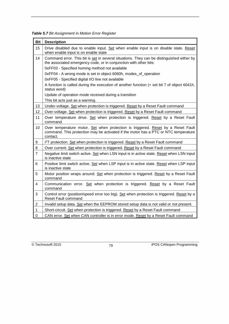
Table 5.7 Bit Assignment in Motion Error Register
Bit Description 15 Drive disabled due to enable input. Set when enable input is on disable state. Reset
when enable input is on enable state 14 Command error. This bit is set in several situations. They can be distinguished either by
the associated emergency code, or in conjunction with other bits: 0xFF03 - Specified homing method not available 0xFF04 - A wrong mode is set in object 6060h, modes_of_operation 0xFF05 - Specified digital I/O line not available A function is called during the execution of another function (+ set bit 7 of object 6041h, status word) Update of operation mode received during a transition This bit acts just as a warning.
13 Under-voltage. Set when protection is triggered. Reset by a Reset Fault command 12 Over-voltage. Set when protection is triggered. Reset by a Reset Fault command 11 Over temperature drive. Set when protection is triggered. Reset by a Reset Fault
command. 10 Over temperature motor. Set when protection is triggered. Reset by a Reset Fault
command. This protection may be activated if the motor has a PTC or NTC temperature contact.
9 I2T protection. Set when protection is triggered. Reset by a Reset Fault command 8 Over current. Set when protection is triggered. Reset by a Reset Fault command 7 Negative limit switch active. Set when LSN input is in active state. Reset when LSN input
is inactive state 6 Positive limit switch active. Set when LSP input is in active state. Reset when LSP input
is inactive state 5 Motor position wraps around. Set when protection is triggered. Reset by a Reset Fault
command 4 Communication error. Set when protection is triggered. Reset by a Reset Fault
command 3 Control error (position/speed error too big). Set when protection is triggered. Reset by a
Reset Fault command 2 Invalid setup data. Set when the EEPROM stored setup data is not valid or not present. 1 Short-circuit. Set when protection is triggered. Reset by a Reset Fault command 0 CAN error. Set when CAN controller is in error mode. Reset by a Reset Fault command
© Technosoft 2015 iPOS CANopen Programming 79

5.3.2. Object 2002h: Detailed Error Register1 The Detailed Error Register displays detailed information about the errors signaled with command Error bit from Motion Error Register. This register also displays the status of software limit switches. A bit set to 1 signals that a specific error has occurred. When the error condition disappears or the error is reset using a Fault Reset command, the corresponding bit is reset to 0. Object description:
Index 2002h Name Detailed Error Register Object code VAR Data type UNSIGNED16
Entry description: Access RO PDO mapping Possible Units - Value range 0 … 65535 Default value 0
Table 5.8 Bit Assignment in Detailed Error Register
Bit Description 15 Reserved 14 Enable circuit hardware error 13 Self check error 12 Reserved 11 Motionless start failed 10 Encoder broken wire 9 Update ignored for S-curve 8 S-curve parameters caused and invalid profile. UPD instruction was ignored. 7 Negative software limit switch is active. 6 Positive software limit switch is active. 5 Cancelable call instruction received while another cancelable function was
active. 4 UPD instruction received while AXISON was executed. The UPD instruction was
ingnored and it must be sent again when AXISON is completed. 3 A call to an inexistent function was received. 2 A call to an inexistent homing routine was received. 1 A RET/RETI instruction was executed while no function/ISR was active.
1 Available starting with firmware revision D.
© Technosoft 2015 iPOS CANopen Programming 80

0 The number of nested function calls exceeded the length of TML stack. Last function call was ignored.
5.3.3. Object 605Ah: Quick stop option code This object determines what action should be taken if the quick stop function is executed. The slow down ramp is a deceleration value set by the Profile acceleration object, index 6083h. The quick stop ramp is a deceleration value set by the Quick stop deceleration object, index 6085h. Object description:
Index 605Ah Name Quick stop option code Object code VAR Data type INTEGER16
Entry description: Access RW PDO mapping No Value range -32768 … 32767 Default value 2
Data description: Value Description -32768…-1 Manufacturer specific 0 Disable drive function 1 Slow down on slow down ramp
and transit into Switch On Disabled
2 Slow down on quick stop ramp and transit into Switch On Disabled
3 Reserved 4 Reserved 5 Slow down on slow down ramp
and stay in Quick Stop Active 6 Slow down on quick stop ramp
and stay in Quick Stop Active 7…32767 Reserved
© Technosoft 2015 iPOS CANopen Programming 81

5.3.4. Object 605Bh: Shutdown option code This object determines what action is taken if when there is a transition from Operation Enabled state to Ready to Switch On state. The slow down ramp is a deceleration value set by the Profile acceleration object, index 6083h. Object description:
Index 605Bh Name Shutdown option code Object code VAR Data type INTEGER16
Entry description: Access RW PDO mapping No Value range -32768 … 32767 Default value 0
Data description: Value Description -32768…-1 Manufacturer specific 0 Disable drive function (switch-off
the drive power stage) 1 Slow down on slow down ramp
and disable the drive function 2…32767 Reserved
5.3.5. Object 605Ch: Disable operation option code This object determines what action is taken if when there is a transition from Operation Enabled state Switched On state. The slow down ramp is a deceleration value set by the Profile acceleration object, index 6083h. Object description:
Index 605Ch Name Disable operation option code Object code VAR Data type INTEGER16
Entry description: Access RW PDO mapping No Value range -32768 … 32767
© Technosoft 2015 iPOS CANopen Programming 82

Default value 1 Data description:
Value Description -32768…-1 Manufacturer specific 0 Disable drive function (switch-off
the drive power stage) 1 Slow down on slow down ramp
and disable the drive function 2…32767 Reserved
5.3.6. Object 605Dh: Halt option code This object determines what action is taken if when the halt command is executed. The slow down ramp is a deceleration value set by the Profile acceleration object, index 6083h. The quick stop ramp is a deceleration value set by the Quick stop deceleration object, index 6085h. Object description:
Index 605Dh Name Halt option code Object code VAR Data type INTEGER16
Entry description: Access RW PDO mapping No Value range -32768 … 32767 Default value 1
Data description: Value Description -32768…-1 Manufacturer specific 0 Reserved 1 Slow down on slow down ramp
and stay in Operation Enabled 2 Slow down on quick stop ramp
and stay in Operation Enabled 3…32767 Reserved
© Technosoft 2015 iPOS CANopen Programming 83

5.3.7. Object 605Eh: Fault reaction option code This object determines what action should be taken if a non-fatal error occurs in the drive. The non-fatal errors are by default the following: Under-voltage Over-voltage I2t error –when the internal register ASR bit1 is 0 in setup. Drive over-temperature Motor over-temperature Communication error (when object 6007h option 1 is set) Object description:
Index 605Eh Name Fault reaction option code Object code VAR Data type INTEGER16
Entry description: Access RW PDO mapping No Value range -32768 … 32767 Default value 2
Data description: Value Description -32768…-2 Manufacturer specific -1 No action 0 Disable drive, motor is free to
rotate 1 Reserved 2 Slow down with quick stop ramp 3…32767 Reserved
© Technosoft 2015 iPOS CANopen Programming 84

5.3.8. Object 6007h: Abort connection option code The object sets the action performed by the drive when one of the following events occurs: bus-off, heartbeat and life guarding. Object description:
Index 6007h Name Abort connection option code Object code VAR Data type INTEGER16
Entry description: Access RW PDO mapping Yes Value range -32768…32767 Default value 0
Table 5.9 Abort connection option codes values:
Option code Description -32768…-1 Manufacturer specific (reserved) 0 No action +1 Fault signal - Execute specific fault routine set in
Object 605Eh: Fault reaction option code +2 Disable voltage command +3 Quick stop command +4…+32767 Reserved
5.4. Digital I/O control and status objects
5.4.1. Object 60FDh: Digital inputs The object contains the actual value of the digital inputs available on the drive. Each bit from the object corresponds to a digital input (manufacturer specific or device profile defined). If a bit is SET, then the status of the corresponding input is logical ‘1’ (high). If the bit is RESET, then the corresponding drive input status is logical ‘0’ (low). Remarks: The device profile defined inputs (limit switches, home input and interlock) are mapped also on the manufacturer specific inputs. Hence, when one of these inputs changes the status, then both bits change, from the manufacturer specific list and from the device profile list. The number of available digital inputs is product dependent. Check the drive user manual for the available digital inputs.
© Technosoft 2015 iPOS CANopen Programming 85

Object description: Index 60FDh Name Digital inputs Object code VAR Data type UNSIGNED32
Entry description: Access RO PDO mapping Possible Value range UNSIGNED32 Default value 0
Bit Value Description
Man
ufac
ture
r spe
cific
31 IN15 status 30 IN14 status 29 IN13 status 28 IN12 status 27 IN11 status 26 IN10 status 25 IN9 status 24 IN8 status 23 IN7 status 22 IN6 status 21 IN5 status 20 IN4 status 19 IN3 status 18 IN2 status 17 IN1 status 16 IN0 status
Dev
ice
prof
ile d
efin
ed
15..4 Reserved 3 0 Interlock (Drive enable) activated; drive may apply
power to motor 1 Interlock (Drive enable) deactivated; drive may not
apply power to motor. Enter Switch on disabled state. 2 0 Home switch input status is low
1 Home switch input status is high 1 0 Positive limit switch is inactive
1 Positive limit switch is active 0 0 Negative limit switch is inactive
1 Negative limit switch is active
© Technosoft 2015 iPOS CANopen Programming 86

5.4.2. Object 60FEh: Digital outputs The object controls the digital outputs of the drive. The first sub-index sets the outputs state to high or low if it is allowed by the mask in the second sub-index which defines the outputs that can be controlled. If any of the bits is SET, then the corresponding drive output will be switched to logical ‘1’ (high) and Switched ON. If the bit is RESET, then the corresponding drive output will be switched to logical ‘0’ (low) and Switched OFF. Remarks: The actual number of available digital outputs is product dependent. Check the drive user manual for the available digital outputs. If an unavailable digital output is specified, the drive will issue an emergency message. Object description:
Index 60FEh Name Digital outputs Object code ARRAY Data type UNSIGNED32
Entry description: Sub-index 0 Description Number of entries Access RO PDO mapping No Value range 1…2 Default value 2
Sub-index 1 Description Physical outputs Access RW PDO mapping Possible Value range UNSIGNED32 Default value 0
Sub-index 2 Description Bit mask Access RW PDO mapping Possible
© Technosoft 2015 iPOS CANopen Programming 87

Value range UNSIGNED32 Default value 0
Table 4.7 Bits mask description:
Bit Description
Man
ufac
ture
r Spe
cific
31 OUT15 command 30 OUT14 command 29 OUT13 command 28 OUT12 command 27 OUT11 command 26 OUT10 command 25 OUT9 command 24 OUT8 command 23 OUT7 command 22 OUT6 command 21 OUT5 command 20 OUT4 command 19 OUT3 command 18 OUT2 command 17 OUT1 command 16 OUT0 command
Dev
ice
prof
ile
Def
ined
15…0 Reserved
5.4.2.1. Example: setting digital outputs
Set OUT0 to 1(ON) and OUT1 to 0 (OFF).
1. Set sub-index 1 with the needed outputs states. Set bit 16 to 1 to enable OUT0 and set bit17 to 0 to disable OUT1.
Set in 60FEh sub-index1 to 0x00010000.
2. Set sub-index 2 bit mask only with the output values that need to be changed. Set bit 16 and 17 to 1 to change OUT0 and OUT1 states.
Set in 60FEh sub-index2 to 0x00030000. After the second sub-index is set, the selected outputs will switch their state to the values defined in sub-index 1.
© Technosoft 2015 iPOS CANopen Programming 88

The subindex setting order can also be reversed: set subindex 2 with the outputs that will be controlled. set subindex 1 with the needed output values
5.4.3. Object 2045h: Digital outputs status The actual status of the drive outputs can be monitored using this object. Object description:
Index 2045h Name Digital outputs status Object code VAR Data type UNSIGNED16
Entry description: Access RO PDO mapping Possible Units - Value range UNSIGNED16 Default value No
Data description: Bit Meaning Bit Meaning 15 OUT15 status 7 OUT7 status 14 OUT14 status 6 OUT6 status 13 OUT13 status 5 OUT5 status 12 OUT12 status 4 OUT4 status 11 OUT11 status 3 OUT3 status 10 OUT10 status 2 OUT2 status 9 OUT9 status 1 OUT1 status 8 OUT8 status 0 OUT0 status
If the any of the bits is SET, then the corresponding drive output status is logical ‘1’ (high). If the bit is RESET, then the corresponding drive output status is logical ‘0’ (low).
5.4.4. Object 2102h: Brake status In Motor Setup, one digital output can be assigned as a brake output. The output will be SET or RESET when the motor PWM power is turned OFF or ON. This object will show 1 when the brake output is active and 0 when not. Object description:
Index 2102h
© Technosoft 2015 iPOS CANopen Programming 89

Name Brake status Object code VAR Data type USINT8
Entry description: Access RO PDO mapping Possible Units - Value range 0 or 1 Default value No
5.4.5. Object 2046h: Analogue input: Reference The object contains the actual value of the analog reference applied to the drive. Through this object one can supervise the analogue input dedicated to receive the analogue reference in the external control modes. Object description:
Index 2046h Name Analogue input: Reference Object code VAR Data type UNSIGNED16
Entry description:
Access RO PDO mapping Possible Units - Value range 0 … 65520 Default value No
5.4.6. Object 2047h: Analogue input: Feedback The object contains the actual value of the analogue feedback applied to the drive. Object description:
Index 2047h Name Analogue input: Feedback Object code VAR Data type UNSIGNED16
Entry description:
© Technosoft 2015 iPOS CANopen Programming 90

Access RO PDO mapping Possible Units - Value range 0 … 65520 Default value No
5.4.7. Object 2055h: DC-link voltage The object contains the actual value of the DC-link voltage. The object is expressed in internal voltage units. Object description:
Index 2055h Name Analogue input: DC-link voltage Object code VAR Data type UNSIGNED16
Entry description: Access RO PDO mapping Possible Units DC-VU Value range 0 … 65472 Default value No
The computation formula for the voltage [IU] in [V] is:
][_65520
][][_ IUmeasuredVoltageVurableVDCMaxMeasVmeasuredVoltage ⋅=
where VDCMaxMeasurable is the maximum measurable DC voltage expressed in [V]. You can read this value in the “Drive Info” dialogue, which can be opened from the “Drive Setup”.
5.4.8. Object 2058h: Drive Temperature The object contains the actual drive temperature. The object is expressed in temperature internal units. Object description:
Index 2058h Name Analogue input for drive
temperature Object code VAR Data type UNSIGNED16
© Technosoft 2015 iPOS CANopen Programming 91

Entry description: Access RO PDO mapping Possible Units - Value range 0 … 65535 Default value No
Note: if the drive does not have a temperature sensor, this object should not be used. The computation formula for the temperature [IU] in [°C] is:
3.365520*utAt0oCDriveTempO-Temp[IU] *
65520*ensorGainDriveTempS3.3= Temp[°C]
where DriveTempSensorGain and DriveTempOutAt0oC can be found as Sensor gain and Output at 0 °C in the “Drive Info” dialogue, which can be opened from the “Drive Setup”.
5.4.9. Object 2108h: Filter variable 16bit This object applies a first order low pass filer on a 16 bit variable value. It does not affect the motor control when applied. It can be used only for sampling filtered values of one variable like the motor current. Object description:
Index 2108h Name Filter variable 16bit Object code Record Data type Filter variable record
Entry description: Sub-index 0 Description Number of entries Access RO PDO mapping No Value range 3 Default value 3
Sub-index 1 Description 16 bit variable address
© Technosoft 2015 iPOS CANopen Programming 92

Access RW PDO mapping Possible Value range UNSIGNED16 Default value 0x0230 (adr. or motor current)
Sub-index 2 Description Filter strength Access RW PDO mapping Possible Value range UNSIGNED16 Default value 50
Sub-index 3 Description Filtered variable 16bit Access RO PDO mapping Possible Value range 0 -32767 Default value -
How it works: Sub-index 1 sets the filtered variable address. To find a variable address, in EasySetup or Easy Motion Studio, click View/ Command Interpreter. The communication must be online with the drive. Write the desired variable name with a ? in front and press Enter.
The variable address can be found between the parenthesis. Sub-index 2 sets the filter strength. The filter is strongest when Sub-index 2 = 0 and weakest when it is 32767. A strong filter increases the time lag between the unfiltered variable change and the filtered value reaching that value. Sub-index 3 shows the filtered value of the 16 bit variable whose address is declared in Sub-index 1.
© Technosoft 2015 iPOS CANopen Programming 93

5.5. Protections Setting Objects
5.5.1. Object 607Dh: Software position limit The object sets the maximal and minimal software position limits. If the actual position is lower than the negative position limit or higher than the positive one, a software position limit emergency message will be launched. If either of these limits is passed, the motor will start decelerating using the value set in Object 6085h: Quick stop deceleration. Once it has decelerated, the motor will stand still until a new command is given to travel within the space defined by the limits. Remarks: A value of -2147483648 for Minimal position limit and 2147483647 for Maximal position limit disables the position limit check. Object description:
Index 607Dh Name Software position limit Object code ARRAY Data type INTEGER32
Entry description: Sub-index 0 Description Number of entries Access RO PDO mapping No Value range 2 Default value 2
Sub-index 1 Description Minimal position limit Access RW PDO mapping Possible Value range INTEGER32 Default value 0x80000000
Sub-index 2 Description Maximal position limit Access RW PDO mapping Possible Value range INTEGER32
© Technosoft 2015 iPOS CANopen Programming 94

Default value 0x7FFFFFFF
5.5.2. Object 2050h: Over-current protection level The Over-Current Protection Level object together with object Over-Current Time Out (2051h) defines the drive over-current protection limits. The object defines the value of current in the drive, over which the over-current protection will be activated, if lasting more than a time interval that is specified in object 2051h. It is set in current internal units. Object description:
Index 2050h Name Over-current protection level Object code VAR Data type UNSIGNED16
Entry description: Access RW PDO mapping No Units CU Value range 0 … 32767 Default value No
The computation formula for the current [IU] in [A] is:
][65520
2][ IUcurentIpeakAcurrent ⋅⋅
=
where Ipeak is the peak current supported by the drive and current[IU] is the command value for object 2050h.
5.5.3. Object 2051h: Over-current time out The Over-Current time out object together with object Over-Current Protection Limit (2050h) defines the drive over-current protection limits. The object sets the time interval after which the over-current protection is triggered if the drive current exceeds the value set through object 2050h. It is set in time internal units. Object description:
Index 2051h Name Over-current time out Object code VAR Data type UNSIGNED16
Entry description: Access RW PDO mapping Possible
© Technosoft 2015 iPOS CANopen Programming 95
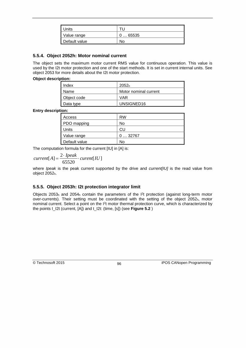
Units TU Value range 0 … 65535 Default value No
5.5.4. Object 2052h: Motor nominal current The object sets the maximum motor current RMS value for continuous operation. This value is used by the I2t motor protection and one of the start methods. It is set in current internal units. See object 2053 for more details about the I2t motor protection. Object description:
Index 2052h Name Motor nominal current Object code VAR Data type UNSIGNED16
Entry description: Access RW PDO mapping No Units CU Value range 0 … 32767 Default value No
The computation formula for the current [IU] in [A] is:
][65520
2][ IUcurentIpeakAcurrent ⋅⋅
=
where Ipeak is the peak current supported by the drive and current[IU] is the read value from object 2052h.
5.5.5. Object 2053h: I2t protection integrator limit Objects 2053h and 2054h contain the parameters of the I2t protection (against long-term motor over-currents). Their setting must be coordinated with the setting of the object 2052h, motor nominal current. Select a point on the I2t motor thermal protection curve, which is characterized by the points I_I2t (current, [A]) and t_I2t: (time, [s]) (see Figure 5.2 )
© Technosoft 2015 iPOS CANopen Programming 96

Figure 5.2 I2t motor thermal protection curve
The points I_I2t and t_I2t on the motor thermal protection curve together with the nominal motor current In define the surface SI2t. If the motor instantaneous current is greater than the nominal current In and the I2t protection is activated, the difference between the square of the instantaneous current and the square of the nominal current is integrated and compared with the SI2t value (see Figure 5.3 ). When the integral equals the SI2t surface, the I2t protection is triggered. Object description:
Index 2053h Name I2t protection integrator limit Object code VAR Data type UNSIGNED32
Entry description: Access RW PDO mapping No Units - Value range 0 … 231-1 Default value No
© Technosoft 2015 iPOS CANopen Programming 97

Figure 5.3 I2t protection implementation
The computation formula for the i2t protection integrator limit (I2TINTLIM) is
262
222
32767)In()t2I_I(TINTLIM2I ⋅
−=
where I_I2t and In are represented in current units (CU).
5.5.6. Object 2054h: I2t protection scaling factor Object description:
Index 2054h Name I2t protection scaling factor Object code VAR Data type UNSIGNED16
Entry description: Access RW PDO mapping No Units - Value range 0 … 65535 Default value No
© Technosoft 2015 iPOS CANopen Programming 98

The computation formula for the i2t protection scaling factor (SFI2T) is
t2I_tS_Ts2T2SFI 26 ⋅=
where Ts_S is the sampling time of the speed control loop [s], and t_I2t is the I2t protection time corresponding to the point on the graphic in Figure 5.2
5.5.7. Object 207Fh: Current limit1 The object defines the maximum current that will pass through the motor. This object is valid only for the configurations using: brushless, DC brushed and stepper closed loop motor. The value is set in current internal units. Object description:
Index 207Fh Name Current actual value Object code VAR Data type Unsigned16
Entry description: Access RW PDO mapping YES Units - Value range 0 … 65535 Default value No
The computation formula for the current_limit [A] to [IU] is:
IpeakALimitCurrentIULimitCurrent
⋅⋅
−=2
65520][_32767][_
where Ipeak is the peak current supported by the drive, Current_Limit[A] is the target current in [A] and Current_Limit[IU] is the target value to be written in object 207Eh.
5.6. Step Loss Detection for Stepper Open Loop configuration1 By using a stepper open loop configuration, the command resolution can be greater than the one used for a normal closed loop configuration. For example if a motor has 200 steps/ revolution and 256 microsteps / step, results in 51200 Internal Units/ revolution position command. If a 1000 lines quadrature encoder is used, it means it will report 4000 Internal Units/ revolution.
1 This feature is available starting with firmware revision F
© Technosoft 2015 iPOS CANopen Programming 99

By using the step loss detection, it means using a stepper in open loop configuration and an incremental encoder to detect lost steps. When the protection triggers, the drive enters Fault state signaling a Control error.
5.6.1. Object 2083h: Encoder Resolution for step loss protection Sets the number of encoder counts the motor does for one full rotation. For example, if the quadrature encoder has 500 lines (2000 counts/rev), 2000 must be written into the object. This object is set automatically when configuring the drive setup. Object description:
Index 2083h Name Encoder resolution for step loss
protection Object code VAR Data type UNSIGNED32
Entry description: Access RW PDO mapping Yes Value range UNSIGNED32 Default value -
5.6.2. Object 2084h: Stepper Resolution for step loss protection Sets the number of microsteps the step motor does for one full rotation. For example, if the motor has 100 steps / revolution (see Figure 5.4) and is controlled with 256 microsteps / step (see Figure 2.2), you must write 100x256=25600 into this object. This object is set automatically when configuring the drive setup. Object description:
Index 2084h Name Stepper resolution for step loss
protection Object code VAR Data type UNSIGNED32
Entry description: Access RW PDO mapping Yes Value range UNSIGNED32 Default value -
© Technosoft 2015 iPOS CANopen Programming 100

Figure 5.4 Motor steps / revolution
Figure 5.5 Motor microsteps / step
© Technosoft 2015 iPOS CANopen Programming 101
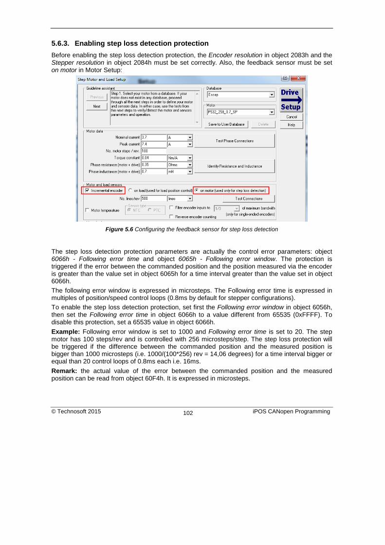
5.6.3. Enabling step loss detection protection Before enabling the step loss detection protection, the Encoder resolution in object 2083h and the Stepper resolution in object 2084h must be set correctly. Also, the feedback sensor must be set on motor in Motor Setup:
Figure 5.6 Configuring the feedback sensor for step loss detection
The step loss detection protection parameters are actually the control error parameters: object 6066h - Following error time and object 6065h - Following error window. The protection is triggered if the error between the commanded position and the position measured via the encoder is greater than the value set in object 6065h for a time interval greater than the value set in object 6066h. The following error window is expressed in microsteps. The Following error time is expressed in multiples of position/speed control loops (0.8ms by default for stepper configurations). To enable the step loss detection protection, set first the Following error window in object 6056h, then set the Following error time in object 6066h to a value different from 65535 (0xFFFF). To disable this protection, set a 65535 value in object 6066h. Example: Following error window is set to 1000 and Following error time is set to 20. The step motor has 100 steps/rev and is controlled with 256 microsteps/step. The step loss protection will be triggered if the difference between the commanded position and the measured position is bigger than 1000 microsteps (i.e. 1000/(100*256) rev = 14,06 degrees) for a time interval bigger or equal than 20 control loops of 0.8ms each i.e. 16ms. Remark: the actual value of the error between the commanded position and the measured position can be read from object 60F4h. It is expressed in microsteps.
© Technosoft 2015 iPOS CANopen Programming 102
5.6.4. Step loss protection setup The following steps are recommended for optimal setup of the step loss protection parameters: Move your motor with the highest velocity and load planned to be used in your application During the movement at maximal speed, read object 60F4h - Following error actual value as often as possible to determine its highest value.
Remark: Following error actual value can be read at every control loop using EasyMotion Studio or Easy Setup by logging the TML variable POSERR.
Add a margin of about 25% to the highest error value determined at previous step and set the new obtained value into object 6065h - Following error window. Activate the step loss detection by writing a non-zero value in object 6066h - Following error time out. Recommended values are between 1 and 10.
5.6.5. Recovering from step loss detection fault When the step loss detection protection is triggered, the drive enters in Fault state. The CANopen master will receive an emergency message from the drive with control error/following error code. In order to exit from Fault state and restart a motion, the following steps must be performed:
• Send fault reset command to the drive. The drive will enter in Switch On Disabled state; • Send Disable voltage command into Control Word. • Send Switch On command into Control Word. At this moment, voltage is applied to the
motor and it will execute the phase alignment procedure again. The position error will be reset automatically.
• Start a homing procedure to find again the motor zero position.
5.6.6. Remarks about Factor Group settings when using step the loss detection When the drive controls stepper motors in open loop, if the factor group settings are activated they are automatically configured for correspondence between motor position in user units and microsteps as internal units. Because the motor position is read in encoder counts, it leads to incorrect values reported in objects 6064h Position actual value and 6062h Position demand value. Only object 6063h Position actual internal value will always show the motor position correctly in encoder counts. If the factor group settings are not used, i.e. all values reported are in internal units (default), both 6064h Position actual value and 6062h Position demand value will provide correct values.
5.7. Drive info objects
5.7.1. Object 1000h: Device Type The object contains information about drive type and its functionality. The 32-bit value contains 2 components of 16-bits: the 16 LSB describe the CiA standard that is followed.
© Technosoft 2015 iPOS CANopen Programming 103

Object description: Index 1000h Name Device type Object code VAR Data type UNSIGNED32
Value description: Access RO PDO mapping NO Value range UNSIGNED32 Default value 60192h for iPOS family
5.7.2. Object 6502h: Supported drive modes This object gives an overview of the operating modes supported on the Technosoft drives. Each bit from the object has assigned an operating mode. If the bit is set then the drive supports the associated operating mode. Object description:
Index 6502h Name Supported drive modes Object code VAR Data type UNSIGNED32
Entry description: Access RO PDO mapping Possible Value range UNSIGNED32 Default value 001F0065h for iPOS family
The modes of operation supported by the Technosoft drives, and their corresponding bits, are the following: Data description: MSB LSB
0 0 x … x 0 0 1 1 0 0 1 0 1 Manufacturer specific rsvd ip hm rsvd tq pv vl pp 31 21 20 … 16 15 7 6 5 4 3 2 1 0
© Technosoft 2015 iPOS CANopen Programming 104

Data description – manufacturer specific: Bit Description 31 … 21 Reserved 20 External Reference Torque Mode 19 External Reference Speed Mode 18 External Reference Position Mode 17 Electronic Gearing Position Mode 16 Electronic Camming Position Mode
5.7.3. Object 1008h: Manufacturer Device Name The object contains the manufacturer device name in ASCII form, maximum 15 characters. Object description:
Index 1008h Name Manufacturer device name Object code VAR Data type Visible String
Entry description: Access Const PDO mapping No Value range No Default value iPOS
© Technosoft 2015 iPOS CANopen Programming 105

5.7.4. Object 100Ah: Manufacturer Software Version The object contains the firmware version programmed on the drive in ASCII form with the maximum length of 15 characters. Object description:
Index 100Ah Name Manufacturer software version Object code VAR Data type Visible String
Entry description: Access Const PDO mapping No Value range No Default value Product dependent
5.7.5. Object 2060h: Software version of a TML application By inspecting this object the user can find out the software version of the TML application (drive setup plus motion setup and eventually cam tables) that is stored in the EEPROM memory of the drive. The object stores the software version coded in a string of 4 elements, grouped in a 32-bit variable. Each byte represents an ASCII character. Object description:
Index 2060h Name Software version of TML
application Object code VAR Data type UNSIGNED32
Entry description: Access RO PDO mapping No Units - Value range No Default value No
Example: If object 2060h contains the value 0x322E3156, then the software version of the TML application is read as: 0x56 – ASCII code of letter V 0x31 – ASCII code of number 1 0x2E – ASCII code of character . (point)
© Technosoft 2015 iPOS CANopen Programming 106

0x32 – ASCII code of number 2 So the version is V1.2.
5.7.6. Object 1018h: Identity Object This object provides general information about the device. Sub-index 01h shows the unique Vendor ID allocated to Technosoft (1A3h). Sub-index 02h contains the Technosoft drive product ID. It can be found physically on the drive label or in Drive Setup/ Drive info button under the field product ID. If the Technosoft product ID is P027.214.E121, subindex 02h will be read as the number 27214121 in decimal. Sub-index 03h shows the Revision number. Sub-index 04h shows the drives Serial number. For example the number 0x4C451158 will be 0x4C (ASCII L); 0x45 (ASCII E); 0x1158 --> the serial number will be LE1158. Object description:
Index 1018h Name Identity Object Object code RECORD Data type Identity
Entry description: Sub-index 00h Description Number of entries Access RO PDO mapping No Value range 1..4 Default value 1
Sub-index 01h
Description Vendor ID Access RO PDO mapping No Value range UNSIGNED32 Default value 000001A3h
Sub-index 02h
Description Product Code Access RO PDO mapping No
© Technosoft 2015 iPOS CANopen Programming 107

Value range UNSIGNED32 Default value Product dependent
Sub-index 03h
Description Revision number Access RO PDO mapping No Value range UNSIGNED32 Default value 0x30313030 (ASCII 0100)
Sub-index 04h
Description Serial number Access RO PDO mapping No Value range UNSIGNED32 Default value Unique number
5.8. Miscellaneous Objects
5.8.1. Object 2025h: Stepper current in open-loop operation In this object one can set the level of the current to be applied when controlling a stepper motor in open loop operation at runtime. Object description:
Index 2025h Name Stepper current in open-loop
operation Object code VAR Data type INTEGER16
Entry description: Access RW PDO mapping Possible Units CU Value range -32768 … 32767 Default value No
© Technosoft 2015 iPOS CANopen Programming 108
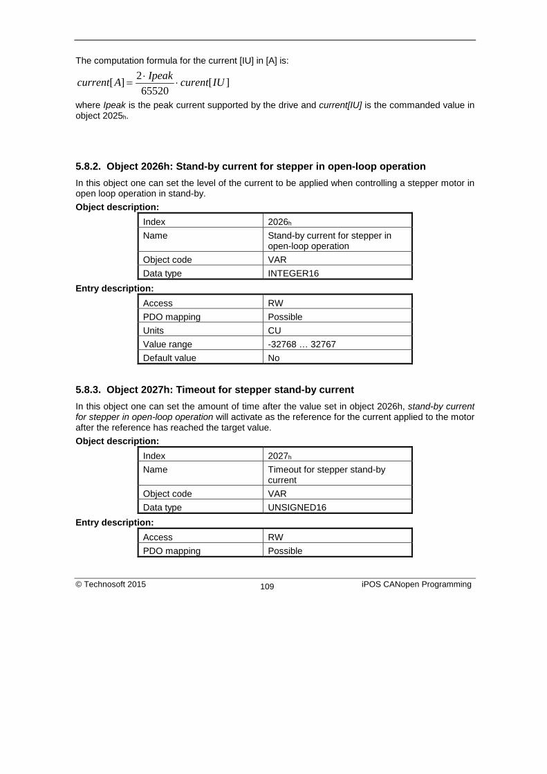
The computation formula for the current [IU] in [A] is:
][65520
2][ IUcurentIpeakAcurrent ⋅⋅
=
where Ipeak is the peak current supported by the drive and current[IU] is the commanded value in object 2025h.
5.8.2. Object 2026h: Stand-by current for stepper in open-loop operation In this object one can set the level of the current to be applied when controlling a stepper motor in open loop operation in stand-by. Object description:
Index 2026h Name Stand-by current for stepper in
open-loop operation Object code VAR Data type INTEGER16
Entry description: Access RW PDO mapping Possible Units CU Value range -32768 … 32767 Default value No
5.8.3. Object 2027h: Timeout for stepper stand-by current In this object one can set the amount of time after the value set in object 2026h, stand-by current for stepper in open-loop operation will activate as the reference for the current applied to the motor after the reference has reached the target value. Object description:
Index 2027h Name Timeout for stepper stand-by
current Object code VAR Data type UNSIGNED16
Entry description: Access RW PDO mapping Possible
© Technosoft 2015 iPOS CANopen Programming 109

Units TU Value range 0 … 65535 Default value No
5.8.4. Object 2075h: Position triggers This object is used in order to define a set of 4 position values whose proximity will be signaled through bits 17-20 of object 1002h, Manufacturer Status Register. If the position actual value is over a certain value set as a position trigger, then the corresponding bit in Manufacturer Status Register will be set. Object description:
Index 2075h Name Position triggers Object code ARRAY Data type INTEGER32
Entry description:
Sub-index 00h Description Number of sub-indexes Access RO PDO mapping No Default value 4
Sub-index 01h – 04h
Description Position trigger 1 - 4 Access RW PDO mapping Possible Value range INTEGER32 Default value No
© Technosoft 2015 iPOS CANopen Programming 110

5.8.5. Object 2085h: Position triggered outputs1 The object controls the digital outputs 0, 1 and 5 in concordance with the position triggers 1, 2 and 4 status from the object 1002h Manufacturer Status Register.
Object description:
Index 2085h Name Position triggered outputs Object code VAR Data type UNSIGNED16
Entry description:
Access RW PDO mapping No Units - Value range 0 … 65535 Default value No
The Position triggered outputs object has the following bit assignment: Table 5.10 Bit Assignment in Position triggered outputs
Bit Value Meaning
12-15 0 Reserved.
11 0
OUT5 = 1 when Position trigger 4 = 0 OUT5 = 0 when Position trigger 4 = 1
1 OUT5 = 0 when Position trigger 4 = 0 OUT5 = 1 when Position trigger 4 = 1
10 0 Reserved.
9 0
OUT1 = 1 when Position trigger 2 = 0 OUT1 = 0 when Position trigger 2 = 1
1 OUT1 = 0 when Position trigger 2 = 0 OUT1 = 1 when Position trigger 2 = 1
8 0
OUT0 = 1 when Position trigger 1 = 0 OUT0 = 0 when Position trigger 1 = 1
1 OUT0 = 0 when Position trigger 1 = 0 OUT0 = 1 when Position trigger 1 = 1
1 This object is available since revision G of the iPOS firmware.
© Technosoft 2015 iPOS CANopen Programming 111

4-7 0 Reserved
31 1 Enable position trigger 4 control of OUT5 0 Disable position trigger 4 control of OUT5
2 0 Reserved
1 1 Enable position trigger 2 control of OUT1 0 Disable position trigger 2 control of OUT1
0 1 Enable position trigger 1 control of OUT0 0 Disable position trigger 1 control of OUT0
Note: Some drives may not have some outputs available. The object will control only the ones that exist.
5.8.6. Object 2076h: Save current configuration This object is used in order to enable saving the current configuration of the operating parameters of the drive. These parameters are the ones that are set when doing the setup of the drive. The purpose of this object is to be able to save the new values of these parameters in order to be re-initialized at subsequent system re-starts. Writing any value in this object will trigger the save in the non-volatile EEPROM memory of the current drive operating parameters. Object description:
Index 2076h Name Save current configuration Object code VAR Data type UNSIGNED16
Entry description: Access WO PDO mapping No Value range UNSIGNED16 Default value -
1 Some outputs may not be available on all drives.
© Technosoft 2015 iPOS CANopen Programming 112

5.8.7. Object 208Bh1: Sin AD signal from Sin/Cos encoder The object contains the actual value of the analogue sine signal of a Sin/Cos encoder. Object description:
Index 208Bh Name Sin AD signal from Sin/Cos
encoder Object code VAR Data type INTEGER16
Entry description: Access RO PDO mapping Possible Units - Value range -32768 … 32767 Default value No
Object 208Ch2: Cos AD signal from Sin/Cos encoder The object contains the actual value of the analogue cosine signal of a Sin/Cos encoder. Object description:
Index 208Ch Name Cos AD signal from Sin/Cos
encoder Object code VAR Data type INTEGER16
Entry description: Access RO PDO mapping Possible Units - Value range -32768 … 32767 Default value No
1 Object 208Bh is available only on firmware F514C and above 2 Object 208Ch is available only on firmware F514C and above
© Technosoft 2015 iPOS CANopen Programming 113

5.8.8. Object 208Eh: Auxiliary Settings Register This object is used as a configuration register that enables various advanced control options. Object description:
Index 208Eh Name Auxiliary Settings Register Object code VAR Data type UNSIGNED16
Entry description: Access RW PDO mapping No Value range UNSIGNED16 Default value -
Table 5.11 Bit Assignment in Auxiliary Settings Register
Bit Value Meaning
4-15 0 Reserved.
3 0 When 6040 bit 14 = 1, at the next update1, the Target Speed Starting
Value is the Actual Speed
1 When 6040 bit 14 = 1, at the next update, the Target Speed Starting Value is zero.
0-2 0 Reserved.
5.8.9. Object 2100h: Number of steps per revolution This object shows the number of motor steps per revolution in case a stepper motor is used. This number is defined in Motor Setup when configuring the motor data. Object description:
Index 2100h Name Number of steps per revolution Object code VAR Data type INTEGER16
1 update can mean a 0 to 1 transition of bit4 in Control Word or setting a new value into object 60FFh while in velocity mode
© Technosoft 2015 iPOS CANopen Programming 114

Entry description: Access RO PDO mapping Yes Value range INTEGER16 Default value -
5.8.10. Object 2101h: Number of microsteps per step This object shows the number of motor microsteps per step in case a stepper open loop configuration is used. This number is defined in Drive Setup. Object description:
Index 2101h Name Number of microteps per step Object code VAR Data type INTEGER16
Entry description: Access RO PDO mapping Yes Value range INTEGER16 Default value -
5.8.11. Object 2103h: Number of encoder counts per revolution This object shows the number of encoder counts for one full motor rotation. For example, if this object indicates 4000 and a 4000IU position command is given, the motor will rotate 1 full mechanical rotation. Remark: this object will not indicate a correct number in case a Brushed DC motor is used. Object description:
Index 2103h Name Number of encoder counts per
revolution Object code VAR Data type INTEGER32
Entry description: Access RO PDO mapping Yes Value range INTEGER32 Default value -
© Technosoft 2015 iPOS CANopen Programming 115

6. Factor group The iPOS drives family offers the possibility to interchange physical dimensions and sizes into the device internal units. This chapter describes the factors that are necessary to do the interchanges.
The factors defined in Factor Group set up a relationship between device internal units and physical units. The actual factors used for scaling are the position factor (object 6093h), the velocity encoder factor (object 6094h), the acceleration factor (object 6097h) and the time encoder factor (object 2071h). Writing a non-zero value into the respective dimension index objects validates these factors. The notation index objects are used for status only and can be set by the user depending on each user-defined value for the factors.
6.1. Factor group objects
6.1.1. Object 607Eh: Polarity
This object is used to multiply by 1 or -1 position and velocity objects. The object applies only to position profile and velocity profile modes of operation.
Object description:
Index 607Eh
Name Polarity
Object code VAR
Data type UNSIGNED8
Entry description:
Access RW
PDO mapping Possible
Value range 0..256
Default value 0
© Technosoft 2015 iPOS CANopen Programming 116

The Polarity object has the following bit assignment: Table 6.1 Bit Assignment in Polarity object:
Bit Bit name Value Meaning
7 Position polarity
0 Multiply by 1 the values of objects 607Ah, 6062h and 6064h
1 Multiply by -1 the values of objects 607Ah, 6062h and 6064h
6 Velocity polarity
0 Multiply by 1 the values of objects 60FFh, 606Bh and 606Ch
1 Multiply by -1 the values of objects 60FFh, 606Bh and 606Ch
5-0 reserved 0 Reserved
6.1.2. Object 6089h: Position notation index
The position notation index is used to scale the following objects: • Position actual value • Position demand value • Target position • Position window • Following error window • Following error actual value
Object description:
Index 6089h
Name Position notation index
Object code VAR
Data type INTEGER8
Entry description:
Access RW
PDO mapping Possible
Value range -128 … 127
Default value 0
© Technosoft 2015 iPOS CANopen Programming 117

6.1.3. Object 608Ah: Position dimension index The position dimension index is used to scale the following objects: Position actual value Position demand value Target position Position window Following error window Following error actual value
Object description:
Index 608Ah
Name Position dimension index
Object code VAR
Data type UNSIGNED8
Entry description:
Access RW
PDO mapping Possible
Value range 0 … 255
Default value 0
6.1.4. Object 608Bh: Velocity notation index The velocity notation index is used to scale the following objects:
• Velocity actual value • Velocity demand value • Target velocity • Profile velocity
Object description:
Index 608Bh
Name Velocity notation index
Object code VAR
Data type INTEGER8
© Technosoft 2015 iPOS CANopen Programming 118
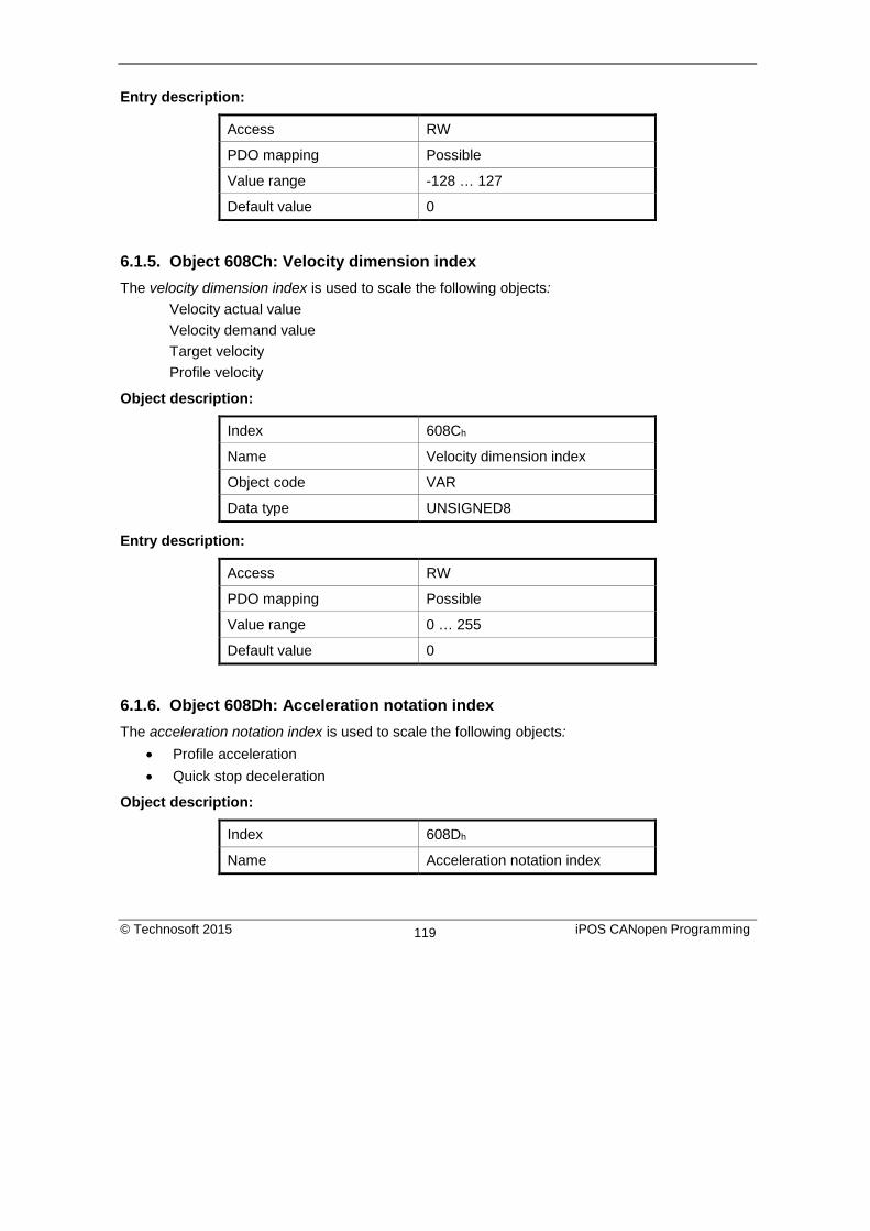
Entry description:
Access RW
PDO mapping Possible
Value range -128 … 127
Default value 0
6.1.5. Object 608Ch: Velocity dimension index The velocity dimension index is used to scale the following objects: Velocity actual value Velocity demand value Target velocity Profile velocity
Object description:
Index 608Ch
Name Velocity dimension index
Object code VAR
Data type UNSIGNED8
Entry description:
Access RW
PDO mapping Possible
Value range 0 … 255
Default value 0
6.1.6. Object 608Dh: Acceleration notation index The acceleration notation index is used to scale the following objects:
• Profile acceleration • Quick stop deceleration
Object description:
Index 608Dh
Name Acceleration notation index
© Technosoft 2015 iPOS CANopen Programming 119

Object code VAR
Data type INTEGER8
Entry description:
Access RW
PDO mapping Possible
Value range -128 … 127
Default value 0
6.1.7. Object 608Eh: Acceleration dimension index The acceleration dimension index is used to scale the following objects: Profile acceleration Quick stop deceleration
Object description:
Index 608Eh
Name Acceleration dimension index
Object code VAR
Data type UNSIGNED8
Entry description: Access RW
PDO mapping Possible
Value range 0 … 255
Default value 0
6.1.8. Object 206Fh: Time notation index The time dimension index is used to scale the following objects: Following error time out Position window time Jerk time Max slippage time out Over-current time out
© Technosoft 2015 iPOS CANopen Programming 120

Object description:
Index 206Fh
Name Time notation index
Object code VAR
Data type INTEGER8
Entry description:
Access RW
PDO mapping Possible
Value range -128 … 127
Default value 0
6.1.9. Object 2070h: Time dimension index The time dimension index is used to scale the following objects:
• Following error time out • Position window time • Jerk time • Max slippage time out • Over-current time out
Object description:
Index 2070h
Name Time dimension index
Object code VAR
Data type UNSIGNED8
Entry description: Access RW
PDO mapping Possible
Value range 0 … 255
Default value 0
© Technosoft 2015 iPOS CANopen Programming 121

6.1.10. Object 6093h: Position factor The position factor converts the desired position (in position units) into the internal format (in increments):
DivisorctorPositionFaNumeratorctorPositionFaUserUnitsPositionIUPosition.
.][][ ×=
Object description:
Index 6093h
Name Position factor
Object code ARRAY
Number of elements 2
Data type UNSIGNED32
Entry description:
Sub-index 01h
Description Numerator
Access RW
PDO mapping Possible
Value range UNSIGNED32
Default value 1
Sub-index 02h
Description Divisor
Access RW
PDO mapping Possible
Value range UNSIGNED32
Default value 1
6.1.11. Object 6094h: Velocity encoder factor The velocity encoder factor converts the desired velocity (in velocity units) into the internal format (in increments).
DivisorrcoderFactoVelocityEnNumeratorrcoderFactoVelocityEnUserUnitsVelocityIUVelocity.
.][][ ×=
© Technosoft 2015 iPOS CANopen Programming 122

Object description:
Index 6094h
Name Velocity encoder factor
Object code ARRAY
Number of elements 2
Data type UNSIGNED32
Entry description:
Sub-index 01h
Description Numerator
Access RW
PDO mapping Possible
Value range UNSIGNED32
Default value 1
Sub-index 02h
Description Divisor
Access RW
PDO mapping Possible
Value range UNSIGNED32
Default value 1
6.1.12. Object 6097h: Acceleration factor The acceleration factor converts the velocity (in acceleration units/sec2) into the internal format (in increments/sampling2).
DivisoronFactorAcceleratiNumeratoronFactorAcceleratiUserUnitsonAcceleratiIUonAccelerati.
.][][ ×=
Object description:
Index 6097h
Name Acceleration factor
Object code ARRAY
© Technosoft 2015 iPOS CANopen Programming 123

Number of elements 2
Data type UNSIGNED32
Entry description:
Sub-index 01h
Description Numerator
Access RW
PDO mapping Possible
Value range UNSIGNED32
Default value 1
Sub-index 02h
Description Divisor
Access RW
PDO mapping Possible
Value range UNSIGNED32
Default value 1
6.1.13. Object 2071h: Time factor The time factor converts the desired time values (in time units) into the internal format (in speed / position loop samplings).
DivisorTimeFactorNumeratorTimeFactorUserUnitsTimeIUTime.
.][][ ×=
Object description:
Index 2071h
Name Time factor
Object code ARRAY
Number of elements 2
Data type UNSIGNED32
© Technosoft 2015 iPOS CANopen Programming 124

Entry description:
Sub-index 01h
Description Numerator
Access RW
PDO mapping Possible
Value range UNSIGNED32
Default value 1
Sub-index 02h
Description Divisor
Access RW
PDO mapping Possible
Value range UNSIGNED32
Default value 1
© Technosoft 2015 iPOS CANopen Programming 125
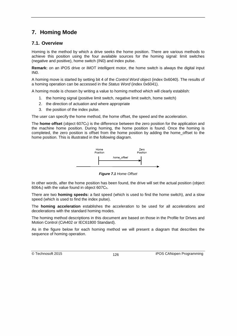
7. Homing Mode
7.1. Overview Homing is the method by which a drive seeks the home position. There are various methods to achieve this position using the four available sources for the homing signal: limit switches (negative and positive), home switch (IN0) and index pulse.
Remark: on an iPOS drive or iMOT intelligent motor, the home switch is always the digital input IN0.
A homing move is started by setting bit 4 of the Control Word object (index 0x6040). The results of a homing operation can be accessed in the Status Word (index 0x6041).
A homing mode is chosen by writing a value to homing method which will clearly establish:
1. the homing signal (positive limit switch, negative limit switch, home switch) 2. the direction of actuation and where appropriate 3. the position of the index pulse.
The user can specify the home method, the home offset, the speed and the acceleration.
The home offset (object 607Ch) is the difference between the zero position for the application and the machine home position. During homing, the home position is found. Once the homing is completed, the zero position is offset from the home position by adding the home_offset to the home position. This is illustrated in the following diagram.
Figure 7.1 Home Offset
In other words, after the home position has been found, the drive will set the actual position (object 6064h) with the value found in object 607Ch.
There are two homing speeds: a fast speed (which is used to find the home switch), and a slow speed (which is used to find the index pulse).
The homing acceleration establishes the acceleration to be used for all accelerations and decelerations with the standard homing modes.
The homing method descriptions in this document are based on those in the Profile for Drives and Motion Control (CiA402 or IEC61800 Standard).
As in the figure below for each homing method we will present a diagram that describes the sequence of homing operation.
© Technosoft 2015 iPOS CANopen Programming 126
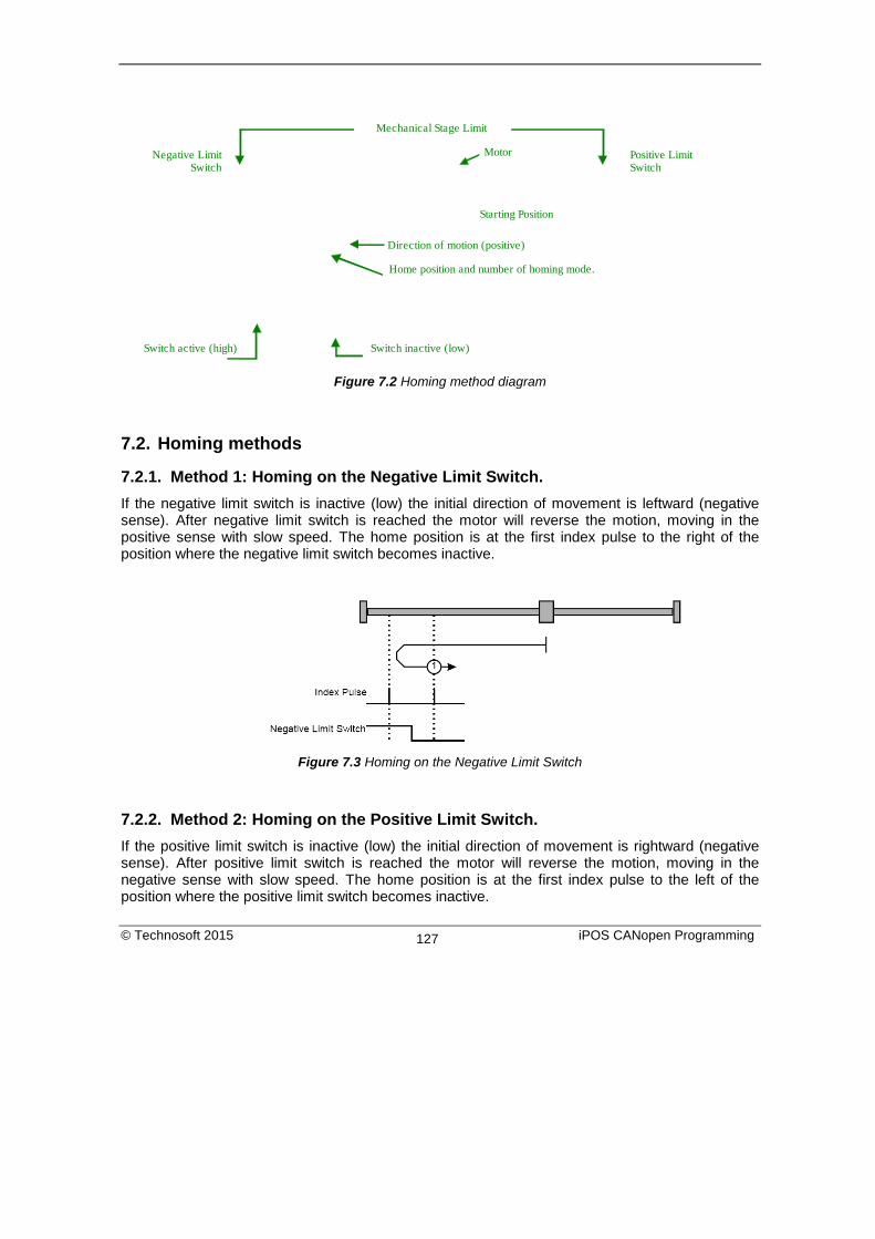
Negative Limit Switch
Mechanical Stage Limit
Motor
Starting Position
Direction of motion (positive)
Home position and number of homing mode.
Switch inactive (low)Switch active (high)
Positive Limit Switch
Figure 7.2 Homing method diagram
7.2. Homing methods
7.2.1. Method 1: Homing on the Negative Limit Switch. If the negative limit switch is inactive (low) the initial direction of movement is leftward (negative sense). After negative limit switch is reached the motor will reverse the motion, moving in the positive sense with slow speed. The home position is at the first index pulse to the right of the position where the negative limit switch becomes inactive.
Figure 7.3 Homing on the Negative Limit Switch
7.2.2. Method 2: Homing on the Positive Limit Switch. If the positive limit switch is inactive (low) the initial direction of movement is rightward (negative sense). After positive limit switch is reached the motor will reverse the motion, moving in the negative sense with slow speed. The home position is at the first index pulse to the left of the position where the positive limit switch becomes inactive.
© Technosoft 2015 iPOS CANopen Programming 127

Figure 7.4 Homing on the Positive Limit Switch
7.2.3. Methods 3 and 4: Homing on the Positive Home Switch and Index Pulse. The home position is at the index pulse either after home switch high-low transition (method 3) or after home switch low-high transition (method 4). The initial direction of movement is dependent on the state of the home switch (if low - move positive, if high - move negative).
Figure 7.5 Homing on the Negative Home Switch and Index Pulse
For method 3, if home input is high the initial direction of movement will be negative, or positive if home input is low, and reverse (with slow speed) after home input low-high transition. The motor will stop at first index pulse after home switch high-low transition. For method 4, if home input is low the initial direction of movement will be positive, or negative if home input is high, and reverse (with slow speed) after home input high-low transition. The motor will stop at first index pulse after home switch low-high transition. In all cases after home switch transition the speed of the movement is slow.
© Technosoft 2015 iPOS CANopen Programming 128

7.2.4. Methods 5 and 6: Homing on the Negative Home Switch and Index Pulse. The home position is at the index pulse either after home switch high-low transition (method 5) or after home switch low-high transition (method 6). The initial direction of movement is dependent on the state of the home switch (if high - move positive, if low - move negative). For method 5, if home input is high the initial direction of movement will be positive, or negative if home input is low, and reverse (with slow speed) after home input low-high transition. The motor will stop at first index pulse after home switch high-low transition. For method 6, if home input is low the initial direction of movement will be negative, or positive if home input is high, and reverse (with slow speed) after home input high-low transition. The motor will stop at first index pulse after home switch low-high transition. In all cases after home switch transition the speed of the movement is slow.
Figure 7.6 Homing on the Negative Home Switch and Index Pulse
7.2.5. Methods 7 to14: Homing on the Negative Home Switch and Index Pulse. These methods use a home switch that is active over only a portion of the travel distance, in effect the switch has a ‘momentary’ action as the axle’s position sweeps past the switch. Using methods 7 to 10 the initial direction of movement is to the right (positive), and using methods 11 to 14 the initial direction of movement is to the left (negative), except the case when the home switch is active at the start of the motion (initial direction of motion is dependent on the edge being sought – the rising edge or the falling edge). The home position is at the index pulse on either side of the rising or falling edges of the home switch, as shown in the following two diagrams. If the initial direction of movement leads away from the home switch, the drive will reverse on encountering the relevant limit switch (negative limit switch for methods 7 to 10, or positive limit switch for methods 11 to 14).
© Technosoft 2015 iPOS CANopen Programming 129

Figure 7.7 Homing on the Home Switch and Index Pulse – Positive Initial Move
Using method 7 the initial move will be positive if home input is low and reverse after home input low-high transition, or move negative if home input is high. Reverse also if the positive limit switch is reached. Stop at first index pulse after home switch active region ends (high-low transition). In all cases after high-low home switch transition the motor speed will be slow. Using method 8 the initial move will be positive if home input is low, or negative if home input is high and reverse after home input high-low transition. Reverse also if the positive limit switch is reached. Stop at first index pulse after home switch active region starts (low-high transition). In all cases after low-high home switch transition the motor speed will be slow. Using method 9 the initial move will be positive and reverse (slow speed) after home input high-low transition. Reverse also if the positive limit switch is reached. Stop at first index pulse after home switch active region starts (low-high transition). Using method 10 the initial move will be positive. Reverse if the positive limit switch is reached, then reverse once again after home input low-high transition. Stop at first index pulse after home switch active region ends (high-low transition). In all cases after high-low home switch transition the motor speed will be slow.
© Technosoft 2015 iPOS CANopen Programming 130
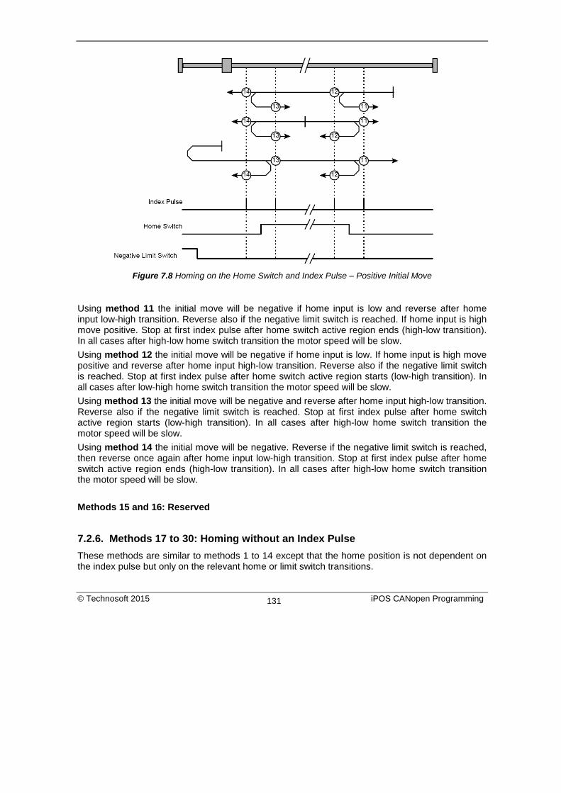
Figure 7.8 Homing on the Home Switch and Index Pulse – Positive Initial Move
Using method 11 the initial move will be negative if home input is low and reverse after home input low-high transition. Reverse also if the negative limit switch is reached. If home input is high move positive. Stop at first index pulse after home switch active region ends (high-low transition). In all cases after high-low home switch transition the motor speed will be slow. Using method 12 the initial move will be negative if home input is low. If home input is high move positive and reverse after home input high-low transition. Reverse also if the negative limit switch is reached. Stop at first index pulse after home switch active region starts (low-high transition). In all cases after low-high home switch transition the motor speed will be slow. Using method 13 the initial move will be negative and reverse after home input high-low transition. Reverse also if the negative limit switch is reached. Stop at first index pulse after home switch active region starts (low-high transition). In all cases after high-low home switch transition the motor speed will be slow. Using method 14 the initial move will be negative. Reverse if the negative limit switch is reached, then reverse once again after home input low-high transition. Stop at first index pulse after home switch active region ends (high-low transition). In all cases after high-low home switch transition the motor speed will be slow. Methods 15 and 16: Reserved
7.2.6. Methods 17 to 30: Homing without an Index Pulse These methods are similar to methods 1 to 14 except that the home position is not dependent on the index pulse but only on the relevant home or limit switch transitions.
© Technosoft 2015 iPOS CANopen Programming 131

Using method 17 if the negative limit switch is inactive (low) the initial direction of movement is leftward (negative sense). After negative limit switch reached the motor will reverse the motion, moving in the positive sense with slow speed. The home position is at the right of the position where the negative limit switch becomes inactive. Using method 18 if the positive limit switch is inactive (low) the initial direction of movement is rightward (negative sense). After positive limit switch reached the motor will reverse the motion, moving in the negative sense with slow speed. The home position is at the left of the position where the positive limit switch becomes inactive. For example methods 19 and 20 are similar to methods 3 and 4 as shown in the following diagram.
Figure 7.9 Homing on the Positive Home Switch
Using method 19, if home input is high, the initial direction of movement will be negative, or positive if home input is low, and reverse (with slow speed) after home input low-high transition. The motor will stop right after home switch high-low transition. Using method 20, if home input is low, the initial direction of movement will be positive, or negative if home input is high, and reverse (with slow speed) after home input high-low transition. The motor will stop after right home switch low-high transition. Using method 21, if home input is high, the initial direction of movement will be positive, or negative if home input is low, and reverse (with slow speed) after home input low-high transition. The motor will stop right after home switch high-low transition. Using method 22, if home input is low, the initial direction of movement will be negative, or positive if home input is high, and reverse (with slow speed) after home input high-low transition. The motor will stop right after home switch low-high transition. Using method 23 the initial move will be positive if home input is low and reverse after home input low-high transition, or move negative if home input is high. Reverse also if the positive limit switch is reached. Stop right after home switch active region ends (high-low transition). Using method 24 the initial move will be positive if home input is low, or negative if home input is high and reverse after home input high-low transition. Reverse also if the positive limit switch is reached. Stop right after home switch active region starts (low-high transition).
© Technosoft 2015 iPOS CANopen Programming 132
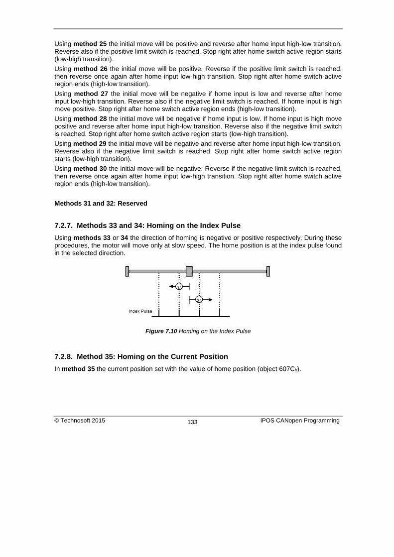
Using method 25 the initial move will be positive and reverse after home input high-low transition. Reverse also if the positive limit switch is reached. Stop right after home switch active region starts (low-high transition). Using method 26 the initial move will be positive. Reverse if the positive limit switch is reached, then reverse once again after home input low-high transition. Stop right after home switch active region ends (high-low transition). Using method 27 the initial move will be negative if home input is low and reverse after home input low-high transition. Reverse also if the negative limit switch is reached. If home input is high move positive. Stop right after home switch active region ends (high-low transition). Using method 28 the initial move will be negative if home input is low. If home input is high move positive and reverse after home input high-low transition. Reverse also if the negative limit switch is reached. Stop right after home switch active region starts (low-high transition). Using method 29 the initial move will be negative and reverse after home input high-low transition. Reverse also if the negative limit switch is reached. Stop right after home switch active region starts (low-high transition). Using method 30 the initial move will be negative. Reverse if the negative limit switch is reached, then reverse once again after home input low-high transition. Stop right after home switch active region ends (high-low transition).
Methods 31 and 32: Reserved
7.2.7. Methods 33 and 34: Homing on the Index Pulse Using methods 33 or 34 the direction of homing is negative or positive respectively. During these procedures, the motor will move only at slow speed. The home position is at the index pulse found in the selected direction.
Figure 7.10 Homing on the Index Pulse
7.2.8. Method 35: Homing on the Current Position In method 35 the current position set with the value of home position (object 607Ch).
34
33
© Technosoft 2015 iPOS CANopen Programming 133

7.2.9. Method -1: Homing on the Negative Mechanical Limit and Index Pulse
7.2.9.1. Method -1 based on motor current increase This method applies to all closed loop motor configurations. It does not apply to Stepper Open Loop configurations. Move negative until the “Current threshold” is reached for a specified amount of time, then reverse and stop at the first index pulse. When the motor current is greater than the Homing Current Threshold (index 0x207B) for a specified amount of time in the Homing Current Threshold Time object (index 0x207C), the motor will reverse direction. The home position is at the first index pulse to the right of the negative mechanical limit. At the end of the procedure, the reported motor position will be the one set in Home offset (index 0x607C).
Warning!
The value of Homing Current Threshold must be lower than the drive current limit. Otherwise, the homing will not complete successfully (no homing error will be issued). The current limit is set during setup. See Paragraph 1.3. Setting the current limit. Current Threshold < current limit
Figure 7.11 Homing on the Negative Mechanical Limit and Index Pulse detecting the motor current increase
7.2.9.2. Method -1 based on step loss detection This method applies only to Stepper Open Loop with Encoder on motor (step loss detection) or Encoder on Load. It does not apply to Closed loop configurations or Stepper Open Loop without an incremental encoder present. If a Stepper Open Loop with Encoder on motor (step loss detection) or Encoder on Load configuration is selected, this homing method will work with the Control Error protection parameters set in Drive Setup. Move negative until a control error is detected, then reverse and stop at the first index pulse. The home position is at the first index pulse to the right of the negative mechanical limit. At the end of the procedure, the reported motor position will be the one set in Home offset (index 0x607C).
© Technosoft 2015 iPOS CANopen Programming 134

Figure 7.12 Homing on the Negative Mechanical Limit and Index Pulse detecting a control error
7.2.10. Method -2: Homing on the Positive Mechanical Limit and Index Pulse
7.2.10.1. Method -2 based on motor current increase This method applies to all closed loop motor configurations. It does not apply to Stepper Open Loop configurations. Move positive until the “Current threshold” is reached for a specified amount of time, then reverse and stop at the first index pulse. When the motor current is greater than the Homing Current Threshold (index 0x207B) for a specified amount of time in the Homing Current Threshold Time object (index 0x207C), the motor will reverse direction. The home position is at the first index pulse to the left of the positive mechanical limit. At the end of the procedure, the reported motor position will be the one set in Home offset (index 0x607C).
Warning!
The value of Homing Current Threshold must be lower than the drive current limit. Otherwise, the homing will not complete successfully (no homing error will be issued). The current limit is set during setup. See Paragraph 1.3. Setting the current limit. Current Threshold < current limit
© Technosoft 2015 iPOS CANopen Programming 135

Figure 7.13 Homing on the Positive Mechanical Limit and Index Pulse detecting the motor current increase
7.2.10.2. Method -2 based on step loss detection This method applies only to Stepper Open Loop with Encoder on motor (step loss detection) or Encoder on Load. It does not apply to Closed loop configurations or Stepper Open Loop without an incremental encoder present. If a Stepper Open Loop with Encoder on motor (step loss detection) or Encoder on Load configuration is selected, this homing method will work with the Control Error protection parameters set in Drive Setup. Move positive until a control error is detected, then reverse and stop at the first index pulse. The home position is at the first index pulse to the left of the positive mechanical limit. At the end of the procedure, the reported motor position will be the one set in Home offset (index 0x607C).
Figure 7.14 Homing on the Positive Mechanical Limit and Index Pulse detecting a control error
© Technosoft 2015 iPOS CANopen Programming 136

7.2.11. Method -3: Homing on the Negative Mechanical Limit without an Index Pulse.
7.2.11.1. Method -3 based on motor current increase This method applies to all closed loop motor configurations. It does not apply to Stepper Open Loop configurations. Move negative until the “Current threshold” is reached for a specified amount of time, then reverse and stop at the position set in “Home position”. When the motor current is greater than the Homing Current Threshold (index 0x207B) for specified amount of time set in the Homing Current Threshold Time object (index 0x207C), the motor will reverse direction and stop after it has travelled the value set in Home offset (index 0x607C). At the end of the procedure, the reported motor position will be the one set in Home offset (index 0x607C).
Warning!
The value of Homing Current Threshold must be lower than the drive current limit. Otherwise, the homing will not complete successfully (no homing error will be issued). The current limit is set during setup. See Paragraph 1.3. Setting the current limit. Current Threshold < current limit
Figure 7.15 Homing on the Positive Mechanical Limit without an Index Pulse detecting the motor current
increase
7.2.11.2. Method -3 based on step loss detection This method applies only to Stepper Open Loop with Encoder on motor (step loss detection) or Encoder on Load. It does not apply to Closed loop configurations or Stepper Open Loop without an incremental encoder present. If a Stepper Open Loop with Encoder on motor (step loss detection) or Encoder on Load configuration is selected, this homing method will work with the Control Error protection parameters set in Drive Setup. When the motor reaches the mechanical limit and detects a Control Error, it will consider the mechanical limit position as the home position. Move negative until a control error is detected, then reverse and stop at the position set in “Home position”. The motor will reverse direction and stop after it has travelled the value set in Home
© Technosoft 2015 iPOS CANopen Programming 137

offset (index 0x607C). At the end of the procedure, the reported motor position will be the one set in Home offset (index 0x607C).
Figure 7.16 Homing on the Positive Mechanical Limit without an Index Pulse detecting a control error
7.2.12. Method -4: Homing on the Positive Mechanical Limit without an Index Pulse.
7.2.12.1. Method -4 based on motor current increase This method applies to all closed loop motor configurations. It does not apply to Stepper Open Loop configurations. Move positive until the “Current threshold” is reached for a specified amount of time, then reverse and stop at the position set in “Home position”. When the motor current is greater than the Homing Current Threshold (index 0x207B) for specified amount of time set in the Homing Current Threshold Time object (index 0x207C), the motor will reverse direction and stop after it has travelled the absolute value set in Home offset (index 0x607C). At the end of the procedure, the reported motor position will be the one set in Home offset (index 0x607C).
Warning!
The value of Homing Current Threshold must be lower than the drive current limit. Otherwise, the homing will not complete successfully (no homing error will be issued). The current limit is set during setup. See Paragraph 1.3. Setting the current limit. Current Threshold < current limit
© Technosoft 2015 iPOS CANopen Programming 138

Figure 7.17 Homing on the Positive Mechanical Limit without an Index Pulse detecting the motor current
increase
7.2.12.2. Method -4 based on step loss detection This method applies only to Stepper Open Loop with Encoder on motor (step loss detection) or Encoder on Load. It does not apply to Closed loop configurations or Stepper Open Loop without an incremental encoder present. If a Stepper Open Loop with Encoder on motor (step loss detection) or Encoder on Load configuration is selected, this homing method will work with the Control Error protection parameters set in Drive Setup. When the motor reaches the mechanical limit and detects a Control Error, it will consider the mechanical limit position as the home position. Move positive until a control error is detected, then reverse and stop at the position set in “Home position”. The motor will reverse direction and stop after it has travelled the value set in Home offset (index 0x607C). At the end of the procedure, the reported motor position will be the one set in Home offset (index 0x607C).
Figure 7.18 Homing on the Positive Mechanical Limit without an Index Pulse detecting the motor current
increase
© Technosoft 2015 iPOS CANopen Programming 139

7.3. Homing Mode Objects This chapter describes the method by which the drive seeks the home position. There are 35 built-in homing methods, as described in paragraph 7.1. Using the EasyMotion Studio software, one can alter each of these homing methods to create a custom homing method. You can select which homing method to be used by writing the appropriate number in the object 6098h homing method. The user can specify the speeds and acceleration to be used during the homing. There is a further object homing offset that allows the user to displace zero in the user’s coordinate system from the home position. In the homing mode, the bits in control word and status word have the following meaning:
7.3.1. Control word in homing mode MSB LSB
See 6040h Halt See 6040h Reserved Homing operation start See 6040h 15 9 8 7 6 5 4 3 0
Table 7.1 Control Word bits description for Homing Mode
Name Value Description
Homing operation start
0 Homing mode inactive 0 -> 1 Start homing mode 1 Homing mode active 1 -> 0 Interrupt homing mode
Halt 0 Execute the instruction of bit 4 1 Stop drive with homing acceleration
7.3.2. Status word in homing mode MSB LSB
See 6041h Homing error
Homing attained
See 6041h
Target reached
See 6041h
15 14 13 12 11 10 9 0
© Technosoft 2015 iPOS CANopen Programming 140

Table 7.2 Status Word bits description for Homing Mode
Name Value Description
Target reached
0 Halt = 0: Home position not reached Halt = 1: Drive decelerates
1 Halt = 0: Home position reached Halt = 1: Velocity of drive is 0
Homing attained
0 Homing mode not yet completed 1 Homing mode carried out successfully
Homing error 0 No homing error 1 Homing error occurred; homing mode not carried out successfully.
Table 7.3 Definition of bit 10,bit 12 and bit 13
Bit 13 Bit 12 Bit 10 Definition 0 0 0 Homing procedure is in progress 0 0 1 Homing procedure is interrupted or not started 0 1 0 Homing is attained, but target is not reached 0 1 1 Homing procedure is completed successfully 1 0 0 Homing error occurred, velocity is not 0 1 0 1 Homing error occurred, velocity is 0 1 1 X reserved
7.3.3. Object 607Ch: Home offset The home offset will be set as the new drive position (reported in object 6064h) after a homing procedure is finished. An exception applies only to the homing motions -3 and -4. See their description for more details. Object description:
Index 607Ch Name Home offset Object code VAR Data type INTEGER32
Entry description: Access RW PDO mapping Possible Units PU Value range INTEGER32
© Technosoft 2015 iPOS CANopen Programming 141

Default value 0
7.3.4. Object 6098h: Homing method The homing method determines the method that will be used during homing. Object description:
Index 6098h Name Homing method Object code VAR Data type INTEGER8
Entry description:
Access RW PDO mapping Possible Value range INTEGER8 Default value 0
Data description: Value Description -128 … -1 Reserved 0 No homing operation required 1 … 35 Methods 1 to 35 36 … 127 reserved
There are 35 built-in homing methods, conforming to DSP402 device profile. Using the EasyMotion Studio software, one can alter each of these homing methods to create a custom one.
7.3.5. Object 6099h: Homing speeds This object defines the speeds used during homing. It is given in velocity units. There are 2 homing speeds; in a typical cycle the faster speed is used to find the home switch and the slower speed is used to find the index pulse. Object description:
Index 6099h Name Homing speeds Object code ARRAY Data type UNSIGNED32
Entry description: Sub-index 0 Description Number of entries
© Technosoft 2015 iPOS CANopen Programming 142

Access RO PDO mapping No Value range 2 Default value 2
Sub-index 1 Description Speed during search for switch Access RW PDO mapping Possible Value range UNSIGNED32 Default value 0
Sub-index 2 Description Speed during search for zero Access RW PDO mapping Possible Value range UNSIGNED32 Default value 0
7.3.6. Object 609Ah: Homing acceleration The homing acceleration establishes the acceleration to be used for all the accelerations and decelerations with the standard homing modes and is given in acceleration units. Object description:
Index 609Ah Name Homing acceleration Object code VAR Data type UNSIGNED32
Entry description: Access RW PDO mapping Possible Units AU Value range UNSIGNED32 Default value -
© Technosoft 2015 iPOS CANopen Programming 143

7.3.7. Object 207Bh: Homing current threshold The Homing Current Threshold Level object together with object Homing current threshold time (207Ch) defines the protection limits when reaching a mechanical stop during homing methods -1,-2,-3 and -4. The object defines the value of current in the drive, over which the homing procedure determines that the mechanical limit has been reached when it lasts more than the time interval specified in object 207Ch. The current is set in internal units.
Warning!
The value of Homing Current Threshold must be lower than the drive current limit. Otherwise, the homing will not complete successfully (no homing error will be issued). The current limit is set during setup. See Paragraph 1.3. Setting the current limit. Current Threshold < current limit
Object description:
Index 207Bh Name Homing current threshold Object code VAR Data type INTEGER16
Entry description: Access RW PDO mapping Possible Units CU Value range -32768 … 32767 Default value No
7.3.8. Object 207Ch: Homing current threshold time The Homing current threshold time object together with object Homing current threshold (207Bh) defines the protection limits when reaching a mechanical stop during homing methods -1,-2,-3 and -4. The object sets the time interval after the homing current threshold is exceeded. After this time is completed without the current dropping below the threshold, the next step in the homing shall be executed. It is set in time internal units. Object description:
Index 207Ch Name Homing current threshold time Object code VAR Data type UNSIGNED16
Entry description: Access RW PDO mapping Possible
© Technosoft 2015 iPOS CANopen Programming 144

Units TU Value range 0 … 65535 Default value No
7.4. Homing example Execute homing method number 18.
1. Start remote node. Send a NMT message to start the node id 6.
Send the following message:
COB-ID 0
Data 01 06
2. Ready to switch on. Change the node state from Switch on disabled to Ready to switch on by sending the shutdown command via control word associated PDO.
Send the following message:
COB-ID 206
Data 06 00
3. Switch on. Change the node state from Ready to switch on to Switch on by sending the switch on command via control word associated PDO.
Send the following message:
COB-ID 206
Data 07 00
4. Enable operation. Change the node state from Switch on to Operation enable by sending the enable operation command via control word associated PDO.
Send the following message:
COB-ID 206
Data 0F 00
5. Homing speed during search for zero. Set the speed during search for zero to 150 rpm. By using and 500 lines incremental encoder and 1ms sample rate for position/speed control the corresponding value of object 6099h sub-index 2 expressed in encoder counts per sample is 50000h.
Send the following message (SDO access to object 6099h sub-index 2, 32-bit value 00050000h):
COB-ID 606
Data 23 99 60 02 00 00 05 00
© Technosoft 2015 iPOS CANopen Programming 145
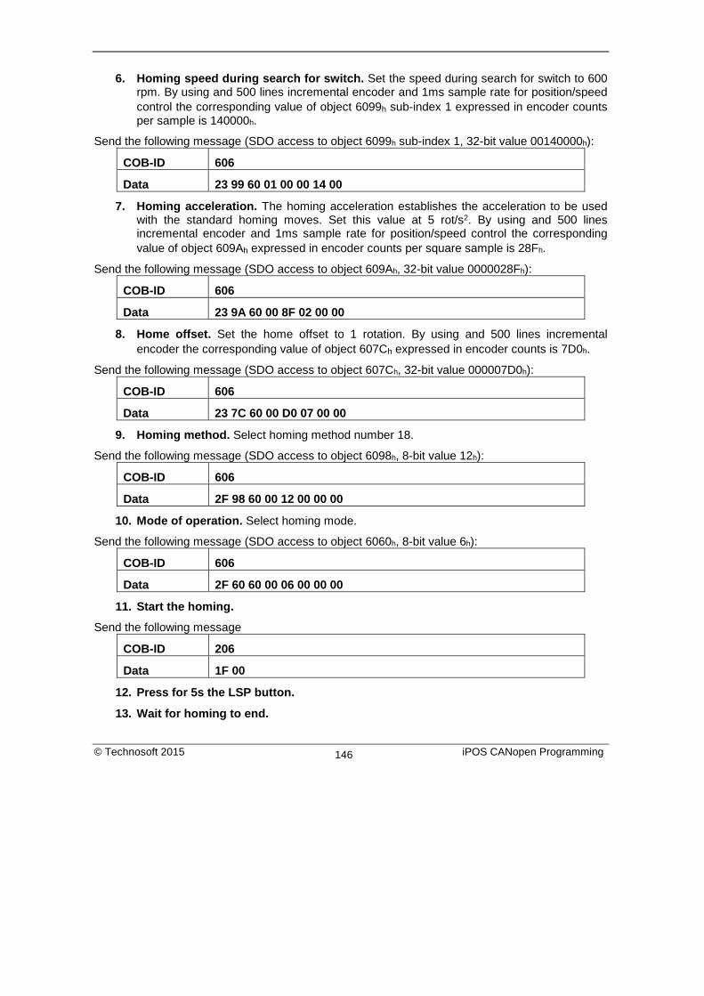
6. Homing speed during search for switch. Set the speed during search for switch to 600 rpm. By using and 500 lines incremental encoder and 1ms sample rate for position/speed control the corresponding value of object 6099h sub-index 1 expressed in encoder counts per sample is 140000h.
Send the following message (SDO access to object 6099h sub-index 1, 32-bit value 00140000h):
COB-ID 606
Data 23 99 60 01 00 00 14 00
7. Homing acceleration. The homing acceleration establishes the acceleration to be used with the standard homing moves. Set this value at 5 rot/s2. By using and 500 lines incremental encoder and 1ms sample rate for position/speed control the corresponding value of object 609Ah expressed in encoder counts per square sample is 28Fh.
Send the following message (SDO access to object 609Ah, 32-bit value 0000028Fh):
COB-ID 606
Data 23 9A 60 00 8F 02 00 00
8. Home offset. Set the home offset to 1 rotation. By using and 500 lines incremental encoder the corresponding value of object 607Ch expressed in encoder counts is 7D0h.
Send the following message (SDO access to object 607Ch, 32-bit value 000007D0h):
COB-ID 606
Data 23 7C 60 00 D0 07 00 00
9. Homing method. Select homing method number 18.
Send the following message (SDO access to object 6098h, 8-bit value 12h):
COB-ID 606
Data 2F 98 60 00 12 00 00 00
10. Mode of operation. Select homing mode.
Send the following message (SDO access to object 6060h, 8-bit value 6h):
COB-ID 606
Data 2F 60 60 00 06 00 00 00
11. Start the homing.
Send the following message
COB-ID 206
Data 1F 00
12. Press for 5s the LSP button.
13. Wait for homing to end.
© Technosoft 2015 iPOS CANopen Programming 146

14. Check the value of motor actual position.
Send the following message (SDO access to object 6064h):
COB-ID 606
Data 40 64 60 00 00 00 00 00
The node will return the value of motor actual position that should be the same as the value of home offset (plus or minus few encoder counts depending on your position tuning).
8. Position Profile Mode
8.1. Overview In Position Profile Mode the drive controls the position.
The Position Profile Mode supports 2 motion modes:
• Trapezoidal profile. The built-in reference generator computes the position profile with a trapezoidal shape of the speed, due to a limited acceleration. The CANopen master specifies the absolute or relative Target Position (index 607Ah), the Profile Velocity (index 6081h) and the Profile Acceleration (6083h)
In relative mode, the position to reach can be computed in 2 ways: standard (default) or additive. In standard relative mode, the position to reach is computed by adding the position increment to the instantaneous position in the moment when the command is executed. In the additive relative mode, the position to reach is computed by adding the position increment to the previous position to reach, independently of the moment when the command was issued. Bit 11 of Control Word activates the additive relative mode.
• S-curve profile the built-in reference generator computes a position profile with an S-curve shape of the speed. This shape is due to the jerk limitation, leading to a trapezoidal or triangular profile for the acceleration and an S-curve profile for the speed. The CANopen master specifies the absolute or relative Target Position (index 607Ah), the Profile Velocity (index 6081h), the Profile Acceleration (6083h) and the jerk rate. The jerk rate is set indirectly via the Jerk time (index 2023h), which represents the time needed to reach the maximum acceleration starting from zero.
There are two different ways to apply target positions to a drive, controlled by the change set immediately bit in Control Word:
8.1.1. Discrete motion profile (change set immediately = 0) After reaching the target position the drive unit signals this status to a CANopen master and then receives a new set-point. After reaching a target position the velocity normally is reduced to zero before starting a move to the next set-point. After the target position is sent to the drive, the CANopen master has to set the new set-point bit in control word. The drive responds with bit set-point acknowledge set in status word. After that, the
© Technosoft 2015 iPOS CANopen Programming 147

master has to reset bit new set-point to 0. Following this action, the drive will signalize that it can accept a new set-point by resetting set-point acknowledge bit in status word after the reference generator has reached the designated demand position.
8.1.2. Continuous motion profile (change set immediately = 1) The drive unit immediately processes the next target position, even if the actual movement is not completed. The drive readapts the actual move to the new target position. In this case, the handshake presented for change set immediately = 0 is not necessary. By setting the new set-point bit, the master will trigger the immediate update of the target position. In this case, if the target position is set as relative, also bit 11 is taken into consideration (with or without additive movement). Remark: In case object 6086h (Motion Profile Type) is set to 3 (jerk-limited ramp = S-curve profile), then change set immediately bit must be 0, else a command error is issued.
8.1.3. Control word in profile position mode MSB LSB See 6040h
Operation Mode
See 6040h
Halt See 6040h
Abs/rel Change set immediately
New set-point
See 6040h
15 12 11 10 9 8 7 6 5 4 3 0
© Technosoft 2015 iPOS CANopen Programming 148

Table 8.1 Control Word bits description for Position Profile Mode
Name Value Description
Operation Mode
0 Trapezoidal profile - In case the movement is relative, do not add the new target position to the old demand position S-curve profile – Stop the motion with S-curve profile (jerk limited ramp)
1 Trapezoidal profile - In case the movement is relative, add the new target position to the old demand position to obtain the new target position S-curve profile – Stop the motion with trapezoidal profile (linear ramp)
New set-point
0 Do not assume target position 1 Assume target position (update the new motion parameters)
Change set immediately
0 Finish the actual positioning and then start the next positioning 1 Interrupt the actual positioning and start the next positioning. Valid
only for linear ramp profile. Abs / rel 0 Target position is an absolute value
1 Target position is a relative value Halt 0 Execute positioning
1 Stop drive with profile acceleration
8.1.4. Status word in profile position mode MSB LSB
See 6041h Following error
Set-point acknowledge
See 6041h
Target reached
See 6041h
15 14 13 12 11 10 9 0
Table 8.2 Status Word bits description for Position Profile Mode
Name Value Description
Target reached
0 Halt = 0: Target position not reached Halt = 1: Drive decelerates
1 Halt = 0: Target position reached Halt = 1: Velocity of drive is 0
Set-point acknowledge
0 Trajectory generator will accept a new set-point 1 Trajectory generator will not accept a new set-point.
Following error
0 No following error 1 Following error
© Technosoft 2015 iPOS CANopen Programming 149

8.2. Position Profile Mode Objects
8.2.1. Object 607Ah: Target position The target position is the position that the drive should move to in position profile mode using the current settings of motion control parameters such as velocity, acceleration, and motion profile type etc. It is given in position units. The position units are user defined. The value is converted to position increments using the position factor (see Chapter 6 Factor group). If Control Word bit 6 = 0 (e.g. absolute positioning), represents the position to reach. If Control Word bit 6 = 1 (e.g. relative positioning), represents the position displacement to do. When Control Word bit 14 = 0, the new position to reach is computed as: motor actual position (6064h) + displacement. When Control Word bit 14 = 1, the new position to reach is computed as: actual demand position (6062h) + displacement. Object description:
Index 607Ah Name Target position Object code VAR Data type INTEGER32
Entry description: Access RW PDO mapping Yes Value range -231 … 231-1 Default value No
8.2.2. Object 6081h: Profile velocity In a position profile, it represents the maximum speed to reach at the end of the acceleration ramp. The profile velocity is given in speed units. The speed units are user defined. The value is converted to internal units using the velocity encoder factor (see Chapter 6 Factor group). If no factor is applied, the profile velocity object receives data as a FIXED32 variable. Meaning that the high part represents encoder increments/sample, and the low part represents a subdivision of an increment. So 65536(0x00010000) = 1 encoder increment / sample. The minimum speed is 1 encoder increment / sample. Object description:
Index 6081h Name Profile velocity Object code VAR Data type UNSIGNED32
© Technosoft 2015 iPOS CANopen Programming 150

Entry description: Access RW PDO mapping Possible Value range UNSIGNED32 Default value -
8.2.3. Object 6083h: Profile acceleration In position or speed profiles, represents the acceleration and deceleration rates used to change the speed between 2 levels. The same rate is used when Quick Stop or Disable Operation commands are received. The profile acceleration is given in acceleration units. The acceleration units are user defined. The value is converted to internal units using the acceleration factor (see Chapter 6 Factor group). If no factor is applied, the same description as object 6081h applies. So 65536 IU = 1 encoder increment / sample2. Object description:
Index 6083h Name Profile acceleration Object code VAR Data type UNSIGNED32
Entry description: Access RW PDO mapping Possible Value range 0..(232-1) Default value -
8.2.4. Object 6085h: Quick stop deceleration The quick stop deceleration is the deceleration used to stop the motor if the Quick Stop command is received and the quick stop option code object (index 605Ah) is set to 2 or 6. It is also used when the fault reaction option code object (index 605Eh) and the halt option code object (index 605Dh) is 2. The quick stop deceleration is given in user-defined acceleration units. Object description:
Index 6085h Name Quick stop deceleration Object code VAR Data type UNSIGNED32
Entry description: Access RW
© Technosoft 2015 iPOS CANopen Programming 151

PDO mapping Possible Value range 0..(232-1) Default value -
8.2.5. Object 2023h: Jerk time In this object you can set the time to use for S-curve profile (jerk-limited ramp set in Object 6086h – Motion Profile Type). The time units are given in ms. Object description:
Index 2023h Name Jerk time Object code VAR Data type UNSIGNED16
Entry description: Access RW PDO mapping Possible Value range 0 … 65535 Default value -
8.2.6. Object 6086h: Motion profile type Object description:
Index 6086h Name Motion profile type Object code VAR Data type INTEGER16
Entry description: Access RW PDO mapping Possible Value range INTEGER16 Default value 0
Data description: Profile code Profile type -32768 … -1 Manufacturer specific (reserved) 0 Linear ramp (trapezoidal profile) 1,2 Reserved 3 Jerk-limited ramp (S-curve) 4 … 32767 Reserved
© Technosoft 2015 iPOS CANopen Programming 152

8.2.7. Object 6062h: Position demand value This object represents the output of the trajectory generation. The position demand value is given in user-defined position units. Object description:
Index 6062h Name Position demand value Object code VAR Data type INTEGER32
Entry description: Access RO PDO mapping Possible Value range -231 … 231-1 Default value -
8.2.8. Object 6063h: Position actual internal value This object represents the actual value of the position measurement device in increments. It can be used as an alternative to position actual value (6064h) in order to save computation time. Object description:
Index 6063h Name Position actual value Object code VAR Data type INTEGER32
Entry description: Access RO PDO mapping Possible Units increments Value range -231 … 231-1 Default value -
8.2.9. Object 6064h: Position actual value This object represents the actual value of the position measurement device. The position actual value is given in user-defined position units. Remark: when using a stepper open loop with encoder on motor configuration (for step loss detection), a position value will not be reported.
© Technosoft 2015 iPOS CANopen Programming 153

Object description: Index 6064h Name Position actual value Object code VAR Data type INTEGER32
Entry description: Access RO PDO mapping Yes Value range -231 … 231-1 Default value -
8.2.10. Object 6065h: Following error window This object defines a range of tolerated position values symmetrically to the position demand value, expressed in position units. If the position actual value is above the following error window for a period larger than the one defined in following error time out, a following error occurs. If the value of the following error window is 232-1, the following control is switched off. The maximum value allowed for the following error window parameter, expressed in increments, is 32767. When this object is written with a higher corresponding value, the following error window parameter will be set to its maximum value (32767) Object description:
Index 6065h Name Following error window Object code VAR Data type UNSIGNED32
Entry description: Access RW PDO mapping Possible Value range UNSIGNED32 Default value -
8.2.11. Object 6066h: Following error time out See 6065h, following error window. The value is given in ms. Object description:
Index 6066h Name Following error time out Object code VAR
© Technosoft 2015 iPOS CANopen Programming 154

Data type UNSIGNED16 Entry description:
Access RW PDO mapping Possible Units TU Value range 0 … 65535 Default value -
8.2.12. Object 6067h: Position window The position window defines a symmetrical range of accepted positions relative to the target position. If the position actual value is within the position window for a time period defined inside the position window time object, this target position is regarded as reached. The position window is given in position units. If the value of the position window is 232-1, the position window control is switched off and the target position will be regarded as reached when the position reference is reached. The maximum value allowed for the position window parameter, expressed in increments, is 32767. Object description:
Index 6067h Name Position window Object code VAR Data type UNSIGNED32
Entry description: Access RW PDO mapping Possible Value range UNSIGNED32 Default value -
8.2.13. Object 6068h: Position window time See description of object 6067h, position window. Object description:
Index 6068h Name Position window time Object code VAR Data type UNSIGNED16
© Technosoft 2015 iPOS CANopen Programming 155

Entry description: Access RW PDO mapping Possible Units TU Value range 0 … 65535 Default value -
8.2.14. Object 60F4h: Following error actual value This object represents the actual value of the following error, given in user-defined position units. Object description:
Index 60F4h Name Following error actual value Object code VAR Data type INTEGER32
Entry description: Access RO PDO mapping Possible Value range INTEGER32 Default value -
8.2.15. Object 60FCh: Position demand internal value This output of the trajectory generator in profile position mode is an internal value using increments as unit. It can be used as an alternative to position demand value (6062h) in order to save computation time. Object description:
Index 60FCh Name Position demand internal value Object code VAR Data type INTEGER32
Entry description: Access RO PDO mapping Possible Units Increments Value range -231 … 231-1 Default value -
© Technosoft 2015 iPOS CANopen Programming 156

8.2.16. Object 2022h: Control effort This object can be used to visualize the control effort of the drive (the reference for the current controller). It is available in internal units. Object description:
Index 2022h Name Control effort Object code VAR Data type INTEGER16
Entry description:
Access RO PDO mapping Yes Value range INTEGER16 Default value -
8.2.17. Object 2081h: Set/Change the actual motor position This object sets the motor position to the value specified. Object description:
Index 2081h Name Set actual position Object code VAR Data type INTEGER32
Entry description: Access RW PDO mapping No Value range -231…231-1 Default value -
8.2.18. Object 2088h1: Actual internal position from sensor on motor This object shows the position value read from the encoder on the motor in increments, in case a dual loop control method is used. The factor group objects have no effect on it.
1 Object 2088h applies only to drives which have a secondary feedback
© Technosoft 2015 iPOS CANopen Programming 157

Object description: Index 2088h Name Actual internal position from
sensor on motor Object code VAR Data type INTEGER32
Entry description: Access RO PDO mapping Possible Units increments Value range -231 … 231-1 Default value -
Object 208Dh1: Auxiliary encoder position This object represents the actual value of the auxiliary position measurement device in internal units. The factor group objects have no effect on it. Object description:
Index 208Dh Name Auxiliary encoder value Object code VAR Data type INTEGER32
Entry description: Access RO PDO mapping Possible Units increments Value range -231 … 231-1 Default value -
1 Object 208Dh is available only drives which have a secondary feedback input
© Technosoft 2015 iPOS CANopen Programming 158

8.3. Position Profile Examples
8.3.1. Absolute trapezoidal example
Execute an absolute trapezoidal profile. First perform 4 rotations, wait motion complete and then set the target position of 16 rotations.
Start remote node. Send a NMT message to start the node id 6.
Send the following message:
COB-ID 0
Data 01 06
Ready to switch on. Change the node state from Switch on disabled to Ready to switch on by sending the shutdown command via control word associated PDO.
Send the following message:
COB-ID 206
Data 06 00
Switch on. Change the node state from Ready to switch on to Switch on by sending the switch on command via control word associated PDO.
Send the following message:
COB-ID 206
Data 07 00
Enable operation. Change the node state from Switch on to Operation enable by sending the enable operation command via control word associated PDO.
Send the following message:
COB-ID 206
Data 0F 00
Mode of operation. Select position mode.
Send the following message (SDO access to object 6060h, 8-bit value 1h):
COB-ID 606
Data 2F 60 60 00 01 00 00 00
Target position. Set the target position to 4 rotations. By using and 500 lines incremental encoder the corresponding value of object 607Ah expressed in encoder counts is 1F40h.
© Technosoft 2015 iPOS CANopen Programming 159

Send the following message (SDO access to object 607Ah 32-bit value 00001F40h):
COB-ID 606
Data 23 7A 60 00 40 1F 00 00
Target speed. Set the target speed normally attained at the end of acceleration ramp to 500 rpm. By using and 500 lines incremental encoder and 1ms sample rate for position/speed control the corresponding value of object 6081h expressed in encoder counts per sample is 10AAACh(16.667 counts/sample).
Send the following message (SDO access to object 6081h, 32-bit value 0010AAACh):
COB-ID 606
Data 23 81 60 00 AC AA 10 00
Start the profile.
Send the following message
COB-ID 206
Data 1F 00
Wait movement to finish.
Reset the set point.
Send the following message
COB-ID 206
Data 0F 00
Target position. Set the target position to 16 rotations. By using and 500 lines incremental encoder the corresponding value of object 607Ah expressed in encoder counts is 7D00h.
Send the following message (SDO access to object 607Ah 32-bit value 00007D00h):
COB-ID 606
Data 23 7A 60 00 00 7D 00 00
Start the profile.
Send the following message
COB-ID 206
Data 1F 00
Wait movement to finish.
Check the value of motor actual position.
Send the following message (SDO access to object 6064h):
© Technosoft 2015 iPOS CANopen Programming 160
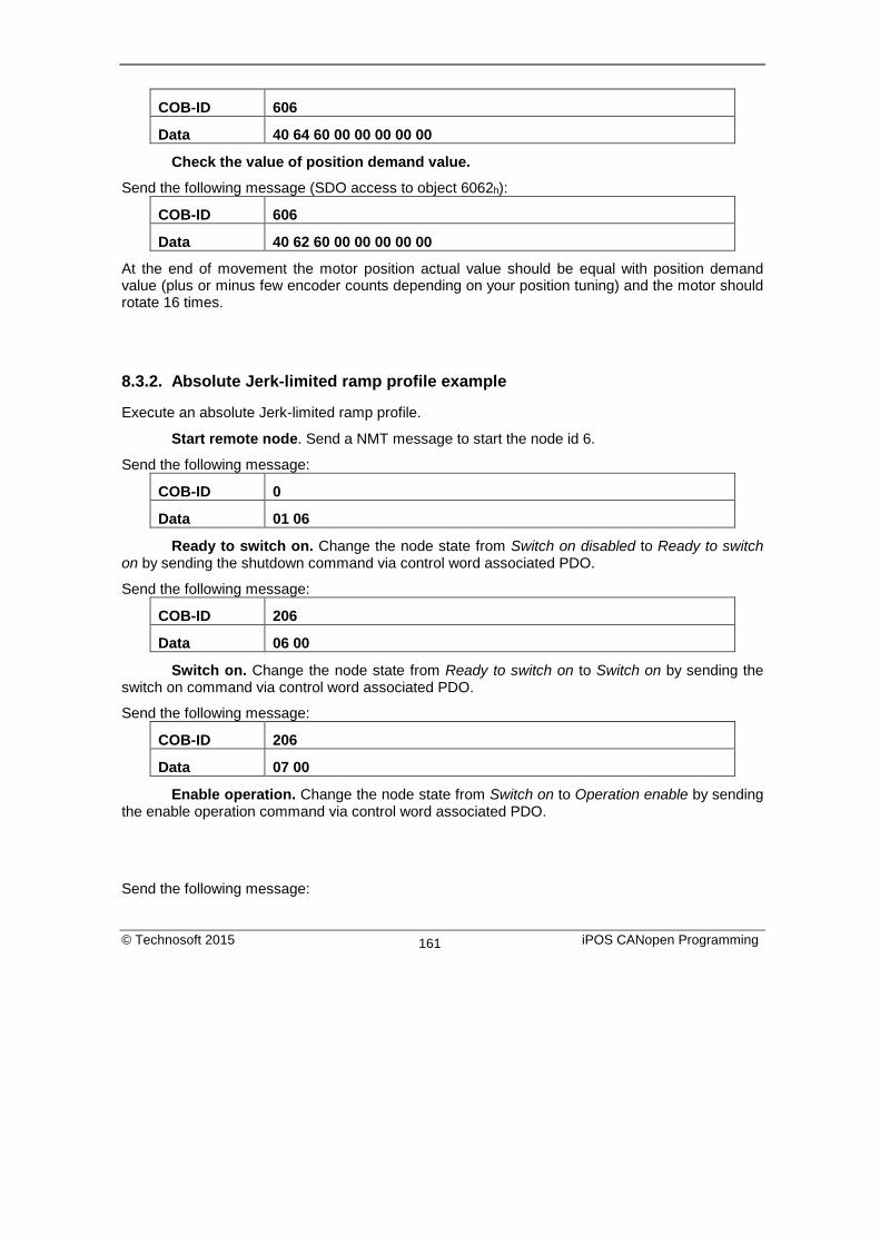
COB-ID 606
Data 40 64 60 00 00 00 00 00
Check the value of position demand value.
Send the following message (SDO access to object 6062h):
COB-ID 606
Data 40 62 60 00 00 00 00 00
At the end of movement the motor position actual value should be equal with position demand value (plus or minus few encoder counts depending on your position tuning) and the motor should rotate 16 times.
8.3.2. Absolute Jerk-limited ramp profile example
Execute an absolute Jerk-limited ramp profile.
Start remote node. Send a NMT message to start the node id 6.
Send the following message:
COB-ID 0
Data 01 06
Ready to switch on. Change the node state from Switch on disabled to Ready to switch on by sending the shutdown command via control word associated PDO.
Send the following message:
COB-ID 206
Data 06 00
Switch on. Change the node state from Ready to switch on to Switch on by sending the switch on command via control word associated PDO.
Send the following message:
COB-ID 206
Data 07 00
Enable operation. Change the node state from Switch on to Operation enable by sending the enable operation command via control word associated PDO.
Send the following message:
© Technosoft 2015 iPOS CANopen Programming 161

COB-ID 206
Data 0F 00
Mode of operation. Select position mode.
Send the following message (SDO access to object 6060h, 8-bit value 1h):
COB-ID 606
Data 2F 60 60 00 01 00 00 00
Motion profile type. Select Jerk-limited ramp.
Send the following message (SDO access to object 6086h, 16-bit value 3h):
COB-ID 606
Data 2B 86 60 00 03 00 00 00
Target position. Set the target position to 5 rotations. By using and 500 lines incremental encoder the corresponding value of object 607Ah expressed in encoder counts is 2710h.
Send the following message (SDO access to object 607Ah 32-bit value 00002710h):
COB-ID 606
Data 23 7A 60 00 10 27 00 00
Target speed. Set the target speed to 150 rpm. By using and 500 lines incremental encoder and 1ms sample rate for position/speed control the corresponding value of object 6081h expressed in encoder counts per sample is 00050000h(5.0 counts/sample).
Send the following message (SDO access to object 6081h, 32-bit value 00050000h):
COB-ID 606
Data 23 81 60 00 00 00 05 00
Jerk time. Set the time to use for Jerk-limited ramp. For more information related to this parameter, see the ESM help
Send the following message (SDO access to object 2023h, 16-bit value 13Bh):
COB-ID 606
Data 2B 23 20 00 3B 01 00 00
Start the profile.
Send the following message
COB-ID 206
Data 1F 00
© Technosoft 2015 iPOS CANopen Programming 162

Wait movement to finish.
Check the value of motor actual position.
Send the following message (SDO access to object 6064h):
COB-ID 606
Data 40 64 60 00 00 00 00 00
Check the value of position demand value.
Send the following message (SDO access to object 6062h):
COB-ID 606
Data 40 62 60 00 00 00 00 00
At the end of movement the motor position actual value should be equal with position demand value (plus or minus few encoder counts depending on your position tuning).
© Technosoft 2015 iPOS CANopen Programming 163

9. Interpolated Position Mode
9.1. Overview The interpolated Position Mode is used to control multiple coordinated axles or a single axle with the need for time-interpolation of set-point data. The Interpolated Position Mode can use the time synchronization mechanism for a time coordination of the related drive units, based on the SYNC and the High Resolution Time Stamp messages (see object 1013 for details). The Interpolated Position Mode allows a host controller to transmit a stream of interpolation data to a drive unit. The interpolation data is better sent in bursts because the drive supports an input buffer. The buffer size is the number of interpolation data records that may be sent to the drive to fill the input buffer. The interpolation algorithm can be defined in the interpolation sub mode select. Linear (PT – Position Time) interpolation is the default interpolation method.
9.1.1. Internal States
Figure 9.1 Internal States for the Interpolated Position Mode
1) See state machine
© Technosoft 2015 iPOS CANopen Programming 164

Interpolation inactive: This state is entered when the device is in state Operation enabled and the Interpolated Position Mode is selected. The drive will accept input data and will buffer it for interpolation calculations, but it does not move the motor. Interpolation active: This state is entered when a device is in state Operation enabled and the Interpolation Position Mode is selected and enabled. The drive will accept input data and will move the motor. State Transitions of the Internal States State Transition 1: NO IP-MODE SELECTED => IP-MODE INACTIVE Event: Select ip-mode with modes of operations while inside Operation enable State Transition 2: IP-MODE INACTIVE => NO IP-MODE SELECTED Event: Select any other mode while inside Operation enable State Transition 3: IP-MODE INACTIVE => IP-MODE ACTIVE Event: Set bit enable ip mode (bit4) of the control word while in ip-mode and Operation enable State Transition 4: IP-MODE ACTIVE => IP-MODE INACTIVE Event: Reset bit enable ip mode (bit4) of the control word while in ip-mode and Operation enable
9.1.2. Control word in interpolated position mode MSB LSB
See 6040h
Stop option See 6040h
Halt See 6040h
Abs / rel
Reserved Enable ip mode
See 6040h
15 12 11 10 9 8 7 6 5 4 3 0
Table 9.1 Control Word bits description for Interpolated Position Mode
Name Value Description Enable ip mode
0 Interpolated position mode inactive 1 Interpolated position mode active
Abs / rel 0 Set position is an absolute value 1 Set position is a relative value
Halt 0 Execute the instruction of bit 4 1 Stop drive with (profile acceleration)
Stop option 0 On transition to inactive mode, stop drive immediately using profile
acceleration
1 On transition to inactive mode, stop drive after finishing the current segment.
© Technosoft 2015 iPOS CANopen Programming 165

9.1.3. Status word in interpolated position mode MSB LSB
See 6041h Reserved ip mode active
See 6041h
Target reached
See 6041h
15 14 13 12 11 10 9 0
Table 9.2 Status Word bits description for Interpolated Position Mode
Name Value Description
Target reached
0 Halt = 0: Final position not reached Halt = 1: Drive decelerates
1 Halt = 0: Final position reached Halt = 1: Velocity of drive is 0
ip mode active
0 Interpolated position mode inactive 1 Interpolated position mode active
9.2. Interpolated Position Objects
9.2.1. Object 60C0h: Interpolation sub mode select In the Interpolated Position Mode the drive supports two interpolation modes: PT (Position – Time) linear interpolation and PVT (Position – Velocity – Time) cubic interpolation. The interpolation mode is selected with Interpolation sub-mode select object. The sub-mode can be changed only when the drive is in Interpolation inactive state. Each change of the interpolation mode will trigger the reset of the buffer associated with the interpolated position mode (because the physical memory available is the same for both the sub-modes, size of each data record is different). Object description:
Index 60C0h Name Interpolation sub mode select Object code VAR Data type INTEGER16
Entry description: Access RW PDO mapping Possible Value range -215 … 215-1 Default value 0
© Technosoft 2015 iPOS CANopen Programming 166

Data description:
Profile code Profile type -32768 … -2 Manufacturer specific (reserved) -1 PVT (Position – Velocity – Time)
cubic interpolation 0 PT (Position – Time) Linear
Interpolation +1…+32767 Reserved
9.2.2. Object 60C1h: Interpolation data record The Interpolation Data Record contains the data words that are necessary to perform the interpolation algorithm. The number of data words in the record is defined by the interpolation data configuration. Object description:
Index 60C1h Name Interpolation data record Object code ARRAY Number of elements 2 Data Type Interpolated Mode dependent
Entry description Sub-index 01h
Description X1: the first parameter of ip function
Access RW PDO mapping Possible Value range Interpolated Mode dependent Default value -
Sub-index 02h Description X2: the second parameter of ip
function Access RW PDO mapping Possible Value range Interpolated Mode dependent Default value -
© Technosoft 2015 iPOS CANopen Programming 167

Description of the sub-indexes: X1 and X2 form a 64-bit data structure as defined below: a) For PVT (Position – Velocity – Time) cubic interpolation: There are 4 parameters in this mode: Position – a 24-bit long integer value representing the target position (relative or absolute). Unit - position increments. Velocity – a 24-bit fixed value representing the end point velocity (16 MSB integer part and 8 LSB fractional part). Unit - increments / sampling Time – a 9-bit unsigned integer value representing the time of a PVT segment. Unit - position / speed loop samplings. Counter – a 7-bit unsigned integer value representing an integrity counter. It can be used in order to have a feedback of the last point sent to the drive and detect errors in transmission. In the example below Position 0 [7…0] represents bits 0..7 of the position value.
Figure 9.2 PVT interpolation point 64-bit data structure
Remarks: - The integrity counter is written in byte 3 of 60C1h Subindex 2, on the most significant 7 bits (bit 1 to bit 7).
Byte 0 Position 0 [7...0]
Byte 1 Position 1 [15...8]
Byte 2 Velocity 0 [15...8]
Byte 3 Position 2 [23...16]
Byte 4 Velocity 1 [23...16]
Byte 5 Velocity 2 [31...24]
Byte 6 Time [7...0]
Byte 7 Counter[6…0] Time[8]
bit7 - - - - bit1 bit0
© Technosoft 2015 iPOS CANopen Programming 168

- The integrity counter is 7 bits long, so it can have a value up to 127. When the integrity counter reaches 127, the next value is 0. b) For PT (Position –Time) linear interpolation: There are 3 parameters in this mode: Position – a 32-bit long integer value representing the target position (relative or absolute). Unit - position increments. Time – a 16-bit unsigned integer value representing the time of a PT segment. Unit - position / speed loop samplings. Counter – a 7-bit unsigned integer value representing an integrity counter. It can be used in order to have a feedback of the last point sent to the drive and detect errors in transmission. In the example below Position[7…0] represents bits 0..7 of the position value.
Figure 9.3 PT interpolation point 64-bit data structure
Remarks: - The integrity counter is written in byte 3 of 60C1h Subindex 2, on the most significant 7 bits (bit 1 to bit 7). - The integrity counter is 7 bits long, so it can have a value up to 127. When the integrity counter reaches 127, the next value is 0.
1 If object 207Ah Interpolated position 1st order time is used, these bits will we overwritten with the value defined in it
Byte 0 Position [7...0]
Byte 1 Position [15...8]
Byte 2 Position [23...16]
Byte 3 Position [31...24]
Byte 4 Time [7...0]1
Byte 5 Time [15...8]1
Byte 6 Reserved
Byte 7 Counter[6…0] Reserved
© Technosoft 2015 iPOS CANopen Programming 169

9.2.3. Object 2072h: Interpolated position mode status The object provides additional status information for the interpolated position mode. Object description:
Index 2072h Name Interpolated position mode status Object code VAR Data type UNSIGNED16
Entry description: Access RO PDO mapping Possible Value range UNSIGNED16 Default value -
Table 9.3 Interpolated position mode status bit description
Bit Value Description
15 0 Buffer is not empty 1 Buffer is empty – there is no point in the buffer.
14 0 Buffer is not low
1 Buffer is low – the number of points from the buffer is equal or less than the low limit set using object 2074h.
13 0 Buffer is not full
1 Buffer is full – the number of points in the buffer is equal with the buffer dimension.
12
0 No integrity counter error
1 Integrity counter error. If integrity counter error checking is enabled and the integrity counter sent by the master does not match the integrity counter of the drive.
11
0 Valid only for PVT (cubic interpolation): Drive has maintained interpolated position mode after a buffer empty condition (the velocity of the last point was 0).
1 Valid only for PVT (cubic interpolation): Drive has performed a quick stop after a buffer empty condition because the velocity of the last point was different from 0
10 … 7 Reserved
6 … 0 Current integrity counter value
© Technosoft 2015 iPOS CANopen Programming 170

Remark: when a status bit changes from this object, an emergency message with the code 0xFF01 will be generated. This emergency message will have mapped object 2072h data onto bytes 3 and 4. The Emergency message contains of 8 data bytes having the following contents:
0-1 2 3-4 5-7 Emergency Error Code (0xFF01)
Error Register (Object 1001h)
Interpolated position status (Object 2072h)
Manufacturer specific error field
To disable the sending of PVT emergency message with ID 0xFF01, the setup variable PVTSENDOFF must be set to 1.
9.2.4. Object 2073h: Interpolated position buffer length Through Interpolated position buffer length object you can change the default buffer length. When writing in this object, the buffer will automatically reset its contents and then re-initialize with the new length. The length of the buffer is the maximum number of interpolation data that can be queued, and does not mean the number of data locations physically available. Remark: It is NOT allowed to write a “0” into this object. Object description:
Index 2073h Name Interpolated position buffer length Object code VAR Data type UNSIGNED16
Entry description: Access WO PDO mapping No Value range UNSIGNED16 Default value 7
9.2.5. Object 2074h: Interpolated position buffer configuration Through this object you can control more in detail the behavior of the buffer. Object description:
Index 2074h Name Interpolated position buffer
configuration Object code VAR Data type UNSIGNED16
© Technosoft 2015 iPOS CANopen Programming 171

Entry description: Access WO PDO mapping No Value range UNSIGNED16 Default value -
Table 9.4 Interpolated position buffer configuration
Bit Value Description
15 0 Nothing 1 Clear buffer and reinitialize buffer internal variables
14 0 Enable the integrity counter error checking 1 Disable the integrity counter error checking
13 0 No change in the integral integrity counter 1 Change internal integrity counter with the value specified in bits 0 to 6
12 0 If absolute positioning is set (bit 6 of control word is 0), the initial position is read from object 2079h. It is used to compute the distance to move up to the first PVT point.
1 If absolute positioning is set (bit 6 of control word is 0), the initial position is the current position demand value. It is used to compute the distance to move up to the first PVT point.
11 ... 8 New parameter for buffer low signaling. When the number of entries in the buffer is equal or less than buffer low value, bit 14 of object 2072h will set.
7 0 No change in the buffer low parameter 1 Change the buffer low parameter with the value specified in bits 8 to 11
6 … 0 New integrity counter value
9.2.6. Object 2079h: Interpolated position initial position Through this object you can set an initial position for absolute positioning in order to be used to compute the distance to move up to the first point. It is given in position units. Object description:
Index 2079h Name Interpolated position initial
position Object code VAR Data type INTEGER32
© Technosoft 2015 iPOS CANopen Programming 172

Entry description: Access RW PDO mapping Possible Value range INTEGER32 Default value 0
9.2.7. Object 207Ah: Interpolated position 1st order time Through this object you can set the time in a PT (Position – Time) Linear Interpolation mode. By setting a value in this object, there is no need to send the time together with the position and integrity counter in Object 60C1h: Interpolation data record. This object is disabled when it is set with 0. It is given in IU which is by default 0.8ms for steppers and 1ms for the other configurations. Object description:
Index 207Ah Name Interpolated position 1st order time Object code VAR Data type UNSIGNED16
Entry description: Access RW PDO mapping Yes Value range UNSIGNED16 Default value 0
9.2.8. Loading the interpolated points If the integrity counter is enabled, the drive considers and loads a valid IP point when it receives a new valid integrity counter number. If the drive receives interpolation data with the same integrity number, it will ignore the point and send an emergency message with the code 0xFF01. If it receives a lower or a +2 higher integrity number, it will ignore the data and send an emergency message with code 0xFF01 and Object 207Ah: Interpolated position 1st order time mapped on bytes 4 and 5 showing and integrity counter error. This error will be automatically reset when the data with correct integrity number will be received. The 7 bit integrity counter can have values between 0 and 127. So when the counter reaches the value 127, the next logical value is 0. After receiving each point, the drive calculates the trajectory it has to execute. Because of this, the points must be loaded after the absolute/relative bit is set in Control Word.
A correct interpolated PT/PVT motion would be like this: • Enter mode 07 in Modes of Operation • set the IP buffer size • Clear the buffer and reinitialize the integrity counter • Set in controlword the bit for absolute or relative motion
© Technosoft 2015 iPOS CANopen Programming 173

• If the motion is absolute, set in 2079h the actual position of the drive (read from object 6063h)
• If the motion is PT, set in object 207Ah a fixed time interval if not supplied in 60C1 subindex2
• Load the first IP points • Start the motion by toggling from 0 to 1 bit4 in controlword • Monitor the interpolated status for buffer low warning (an emergency message will be
sent automatically containing the interpolated status when one of the status bits changes )
• Load more points until buffer full bit is active • Return to monitoring the buffer status and load points until the profile is finished
9.3. PT absolute movement example Execute an absolute PT movement.
Remark: Because this is a demo for a single axis the synchronization mechanism is not used here.
1. Start remote node. Send a NMT message to start the node id 6.
Send the following message:
COB-ID 0
Data 01 06
2. Ready to switch on. Change the node state from Switch on disabled to Ready to switch on by sending the shutdown command via control word associated PDO.
Send the following message:
COB-ID 206
Data 06 00
3. Switch on. Change the node state from Ready to switch on to Switch on by sending the switch on command via control word associated PDO.
Send the following message:
COB-ID 206
Data 07 00
4. Enable operation. Change the node state from Switch on to Operation enable by sending the enable operation command via control word associated PDO.
Send the following message:
COB-ID 206
Data 0F 00
© Technosoft 2015 iPOS CANopen Programming 174
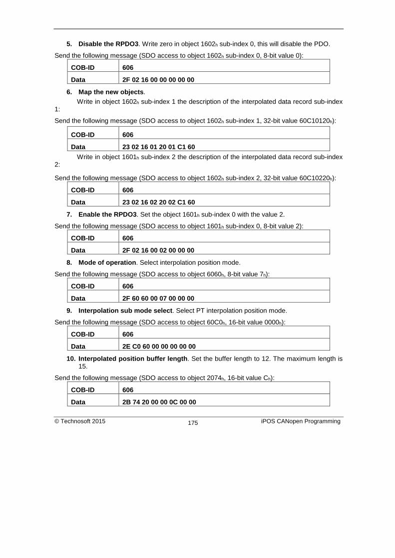
5. Disable the RPDO3. Write zero in object 1602h sub-index 0, this will disable the PDO.
Send the following message (SDO access to object 1602h sub-index 0, 8-bit value 0):
COB-ID 606
Data 2F 02 16 00 00 00 00 00
6. Map the new objects. Write in object 1602h sub-index 1 the description of the interpolated data record sub-index 1:
Send the following message (SDO access to object 1602h sub-index 1, 32-bit value 60C10120h):
COB-ID 606
Data 23 02 16 01 20 01 C1 60 Write in object 1601h sub-index 2 the description of the interpolated data record sub-index 2:
Send the following message (SDO access to object 1602h sub-index 2, 32-bit value 60C10220h):
COB-ID 606
Data 23 02 16 02 20 02 C1 60
7. Enable the RPDO3. Set the object 1601h sub-index 0 with the value 2.
Send the following message (SDO access to object 1601h sub-index 0, 8-bit value 2):
COB-ID 606
Data 2F 02 16 00 02 00 00 00
8. Mode of operation. Select interpolation position mode.
Send the following message (SDO access to object 6060h, 8-bit value 7h):
COB-ID 606
Data 2F 60 60 00 07 00 00 00
9. Interpolation sub mode select. Select PT interpolation position mode.
Send the following message (SDO access to object 60C0h, 16-bit value 0000h):
COB-ID 606
Data 2E C0 60 00 00 00 00 00
10. Interpolated position buffer length. Set the buffer length to 12. The maximum length is 15.
Send the following message (SDO access to object 2074h, 16-bit value Ch):
COB-ID 606
Data 2B 74 20 00 00 0C 00 00
© Technosoft 2015 iPOS CANopen Programming 175
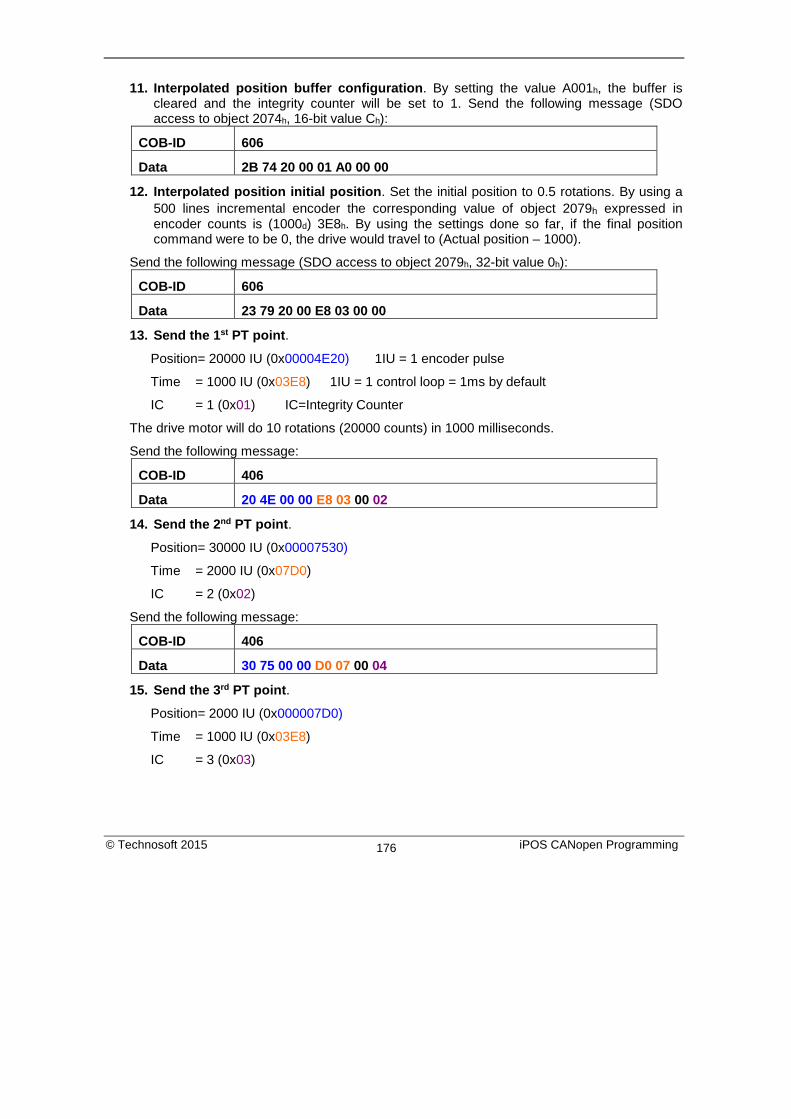
11. Interpolated position buffer configuration. By setting the value A001h, the buffer is cleared and the integrity counter will be set to 1. Send the following message (SDO access to object 2074h, 16-bit value Ch):
COB-ID 606
Data 2B 74 20 00 01 A0 00 00
12. Interpolated position initial position. Set the initial position to 0.5 rotations. By using a 500 lines incremental encoder the corresponding value of object 2079h expressed in encoder counts is (1000d) 3E8h. By using the settings done so far, if the final position command were to be 0, the drive would travel to (Actual position – 1000).
Send the following message (SDO access to object 2079h, 32-bit value 0h):
COB-ID 606
Data 23 79 20 00 E8 03 00 00
13. Send the 1st PT point.
Position= 20000 IU (0x00004E20) 1IU = 1 encoder pulse
Time = 1000 IU (0x03E8) 1IU = 1 control loop = 1ms by default
IC = 1 (0x01) IC=Integrity Counter
The drive motor will do 10 rotations (20000 counts) in 1000 milliseconds.
Send the following message:
COB-ID 406
Data 20 4E 00 00 E8 03 00 02
14. Send the 2nd PT point.
Position= 30000 IU (0x00007530)
Time = 2000 IU (0x07D0)
IC = 2 (0x02)
Send the following message:
COB-ID 406
Data 30 75 00 00 D0 07 00 04
15. Send the 3rd PT point.
Position= 2000 IU (0x000007D0)
Time = 1000 IU (0x03E8)
IC = 3 (0x03)
© Technosoft 2015 iPOS CANopen Programming 176

Send the following message:
COB-ID 406
Data D0 07 00 00 E8 03 00 06
16. Send the last PT point.
Set X1=00000000 h (0 counts); X2=080001F4 (IC=4 (0x08), time =500 (0x01F4))
Position= 0 IU (0x00000000)
Time = 500 IU (0x01F4)
IC = 4 (0x04)
Send the following message:
COB-ID 406
Data 00 00 00 00 F4 01 00 08
17. Start an absolute motion.
Send the following message:
COB-ID 206
Data 1F 00 After the sequences are executed, if the drive actual position before starting the motion was 0, now it should be -1000 counts because of Step 12.
9.4. PVT absolute movement example Execute an absolute PVT movement. The PVT position points will be given as absolute positions.
Remark: Because this is a demo for a single axis the synchronization mechanism is not used here.
Start remote node. Send a NMT message to start the node id 6.
Send the following message:
COB-ID 0
Data 01 06
Ready to switch on. Change the node state from Switch on disabled to Ready to switch on by sending the shutdown command via control word associated PDO.
Send the following message:
COB-ID 206
Data 06 00
© Technosoft 2015 iPOS CANopen Programming 177

Switch on. Change the node state from Ready to switch on to Switch on by sending the switch on command via control word associated PDO.
Send the following message:
COB-ID 206
Data 07 00
Enable operation. Change the node state from Switch on to Operation enable by sending the enable operation command via control word associated PDO.
Send the following message:
COB-ID 206
Data 0F 00
Disable the RPDO3. Write zero in object 1602h sub-index 0, this will disable the PDO.
Send the following message (SDO access to object 1602h sub-index 0, 8-bit value 0):
COB-ID 606
Data 2F 02 16 00 00 00 00 00
Map the new objects. a) Write in object 1602h sub-index 1 the description of the interpolated data record
sub-index 1:
Send the following message (SDO access to object 1602h sub-index 1, 32-bit value 60C10120h):
COB-ID 606
Data 23 02 16 01 20 01 C1 60 b) Write in object 1601h sub-index 2 the description of the interpolated data record
sub-index 2:
Send the following message (SDO access to object 1602h sub-index 2, 32-bit value 60C10220h):
COB-ID 606
Data 23 02 16 02 20 02 C1 60
Enable the RPDO3. Set the object 1601h sub-index 0 with the value 2.
Send the following message (SDO access to object 1601h sub-index 0, 8-bit value 2):
COB-ID 606
Data 2F 02 16 00 02 00 00 00
Mode of operation. Select interpolation position mode.
© Technosoft 2015 iPOS CANopen Programming 178

Send the following message (SDO access to object 6060h, 8-bit value 7h):
COB-ID 606
Data 2F 60 60 00 07 00 00 00
Interpolation sub mode select. Select PVT interpolation position mode.
Send the following message (SDO access to object 60C0h, 16-bit value FFFFh):
COB-ID 606
Data 2E C0 60 00 FF FF 00 00
Interpolated position buffer length. Set the buffer length to 15. The maximum length is 15.
Send the following message (SDO access to object 2074h, 16-bit value Ch):
COB-ID 606
Data 2B 73 20 00 00 0F 00 00
Interpolated position buffer configuration. By setting the value B000h, the buffer is cleared and the integrity counter will be set to 0.
Send the following message (SDO access to object 2074h, 16-bit value B000h):
COB-ID 606
Data 2B 74 20 00 00 B0 00 00
Send the 1st PVT point.
Position = 88 IU (0x000058) 1IU = 1 encoder pulse
Velocity = 3.33 IU (0x000354) 1IU = 1 encoder pulse/ 1 control loop
Time = 55 IU (0x37) 1IU = 1 control loop = 1ms by default
IC = 0 (0x00) IC=Integrity Counter
Send the following message:
COB-ID 406
Data 58 00 54 00 03 00 37 00
Send the 2nd PVT point.
Position = 370 IU (0x000172)
Velocity = 6.66 IU (0x0006A8)
Time = 55 IU (0x37)
IC = 1 (0x01)
© Technosoft 2015 iPOS CANopen Programming 179

Send the following message:
COB-ID 406
Data 72 01 A8 00 06 00 37 02
Send the 3rd PVT point.
Position = 2982 IU (0x000BA6)
Velocity = 6.66 IU (0x0006A8)
Time = 390 IU (0x186)
IC = 2 (0x02)
Send the following message:
COB-ID 406
Data A6 0B A8 00 06 00 86 05
Send the 4th PVT point.
Position = 5631 IU (0x0015FF)
Velocity = 6.66 IU (0x0006A8)
Time = 400 IU (0x190)
IC = 3 (0x03)
Send the following message:
COB-ID 406
Data FF 15 A8 00 06 00 90 07
Send the 5th PVT point.
Position = 5925 IU (0x001725)
Velocity = 3.00 IU (0x000300)
Time = 60 IU (0x3C)
IC = 4 (0x04)
Send the following message:
COB-ID 406
Data 25 17 00 00 03 00 3C 08
Send the 6th PVT point.
Position = 6000 IU (0x001770)
Velocity = 0.00 IU (0x000000)
Time = 50 IU (0x32)
© Technosoft 2015 iPOS CANopen Programming 180

IC = 5 (0x05)
Send the following message:
COB-ID 406
Data 70 17 00 00 00 00 32 0A
Send the 7th PVT point.
Position = 5127 IU (0x001407)
Velocity = -7.5 IU (0xFFF880)
Time = 240 IU (0xF0)
IC = 6 (0x06)
Send the following message:
COB-ID 406
Data 07 14 80 00 F8 FF F0 0C
Send the 8th PVT point.
Position = 3115 IU (0x000C2B)
Velocity = -13.33 IU (0xFFF2AB)
Time = 190 IU (0xBE)
IC = 7 (0x07)
Send the following message:
COB-ID 406
Data 2B 0C AB 00 F2 FF BE 0E
Send the 9th PVT point.
Position = -1686 IU (0xFFF96A)
Velocity = -13.33 IU (0xFFF2AB)
Time = 360 IU (0x168)
IC = 8 (0x08)
Send the following message:
COB-ID 406
Data 6A F9 AB FF F2 FF 68 11
Send the 10nth PVT point.
Position = -7145 IU (0xFFE417)
Velocity = -13.33 IU (0xFFF2AB)
© Technosoft 2015 iPOS CANopen Programming 181
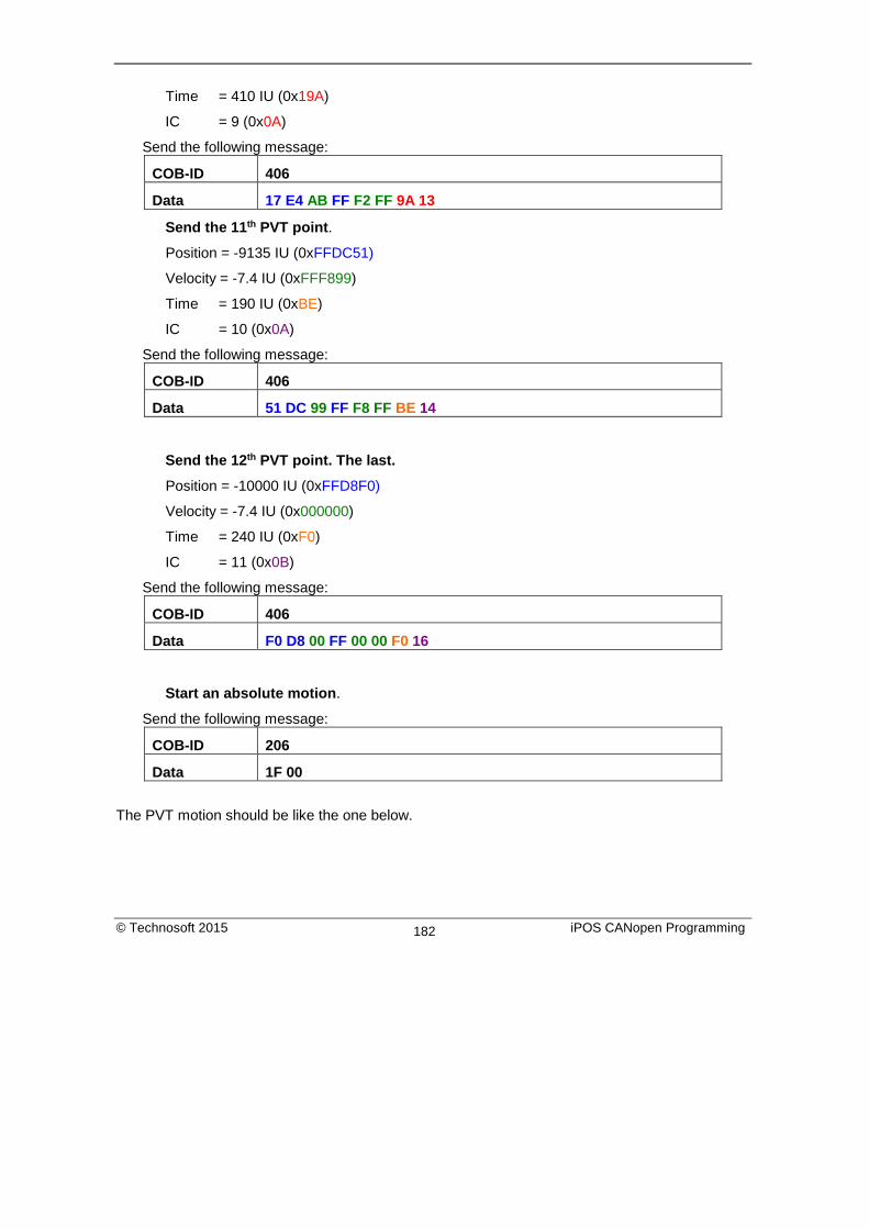
Time = 410 IU (0x19A)
IC = 9 (0x0A)
Send the following message:
COB-ID 406
Data 17 E4 AB FF F2 FF 9A 13
Send the 11th PVT point.
Position = -9135 IU (0xFFDC51)
Velocity = -7.4 IU (0xFFF899)
Time = 190 IU (0xBE)
IC = 10 (0x0A)
Send the following message:
COB-ID 406
Data 51 DC 99 FF F8 FF BE 14
Send the 12th PVT point. The last.
Position = -10000 IU (0xFFD8F0)
Velocity = -7.4 IU (0x000000)
Time = 240 IU (0xF0)
IC = 11 (0x0B)
Send the following message:
COB-ID 406
Data F0 D8 00 FF 00 00 F0 16
Start an absolute motion.
Send the following message:
COB-ID 206
Data 1F 00
The PVT motion should be like the one below.
© Technosoft 2015 iPOS CANopen Programming 182

The motor should rotate 3 positive rotations and another 8 negatively (for a 500 lines encoder). If the initial position before the motion was 0, the final position should be -10000 IU (-5 rotations). All points should be executed within 2.64s, considering the default time base is 1ms.
9.5. PVT relative movement example Execute a relative PVT movement. The PVT position points will be given as a difference between next and last position.
Remark: Because this is a demo for a single axis the synchronization mechanism is not used here.
1. Start remote node. Send a NMT message to start the node id 6.
Send the following message:
COB-ID 0
Data 01 06
2. Ready to switch on. Change the node state from Switch on disabled to Ready to switch on by sending the shutdown command via control word associated PDO.
Send the following message:
COB-ID 206
Data 06 00
3. Switch on. Change the node state from Ready to switch on to Switch on by sending the switch on command via control word associated PDO.
Send the following message:
COB-ID 206
Data 07 00
4. Enable operation. Change the node state from Switch on to Operation enable by sending the enable operation command via control word associated PDO.
© Technosoft 2015 iPOS CANopen Programming 183

Send the following message:
COB-ID 206
Data 0F 00
5. Disable the RPDO3. Write zero in object 1602h sub-index 0, this will disable the PDO.
Send the following message (SDO access to object 1602h sub-index 0, 8-bit value 0):
COB-ID 606
Data 2F 02 16 00 00 00 00 00
6. Map the new objects. a) Write in object 1602h sub-index 1 the description of the interpolated data record
sub-index 1:
Send the following message (SDO access to object 1602h sub-index 1, 32-bit value 60C10120h):
COB-ID 606
Data 23 02 16 01 20 01 C1 60 b) Write in object 1601h sub-index 2 the description of the interpolated data record
sub-index 2:
Send the following message (SDO access to object 1602h sub-index 2, 32-bit value 60C10220h):
COB-ID 606
Data 23 02 16 02 20 02 C1 60
7. Enable the RPDO3. Set the object 1601h sub-index 0 with the value 2.
Send the following message (SDO access to object 1601h sub-index 0, 8-bit value 2):
COB-ID 606
Data 2F 02 16 00 02 00 00 00
8. Mode of operation. Select interpolation position mode.
Send the following message (SDO access to object 6060h, 8-bit value 7h):
COB-ID 606
Data 2F 60 60 00 07 00 00 00
9. Set the relative motion bit. Set in Control Word mapped in RPDO1 the value 4Fh. For an absolute motion, set 0Fh but the example points will not apply.
Remark: if the relative motion bit is not set in control word before the PVT points are loaded, the trajectory will not be calculated correctly.
© Technosoft 2015 iPOS CANopen Programming 184

Send the following message:
COB-ID 206
Data 4F 00
10. Interpolation sub mode select. Select PVT interpolation position mode.
Send the following message (SDO access to object 60C0h, 16-bit value FFFFh):
COB-ID 606
Data 2E C0 60 00 FF FF 00 00
11. Interpolated position buffer length. Set the buffer length to 12. The maximum length is 15.
Send the following message (SDO access to object 2074h, 16-bit value Ch):
COB-ID 606
Data 2B 73 20 00 00 0C 00 00
12. Interpolated position buffer configuration. By setting the value A001h, the buffer is cleared and the integrity counter will be set to 1. Send the following message (SDO access to object 2074h, 16-bit value Ch):
COB-ID 606
Data 2B 74 20 00 01 A0 00 00
13. Interpolated position initial position. Set the initial position to 0 rotations. The object should receive the drives actual position in Internal Units which can be read from object 6063h or 6062h when using steppers in open loop.
Send the following message (SDO access to object 2079h, 32-bit value 0h):
COB-ID 606
Data 23 79 20 00 00 00 00 00
14. Send the 1st PVT point.
Position = 400 IU (0x000190) 1IU = 1 encoder pulse
Velocity = 3.00 IU (0x000300) 1IU = 1 encoder pulse/ 1 control loop
Time = 250 IU (0xFA) 1IU = 1 control loop = 1ms by default
IC = 1 (0x01) IC=Integrity Counter
Send the following message:
COB-ID 406
Data 90 01 00 00 03 00 FA 02
15. Send the 2nd PVT point.
Position = 1240 IU (0x0004D8)
© Technosoft 2015 iPOS CANopen Programming 185

Velocity = 6.00 IU (0x000600)
Time = 250 IU (0xFA)
IC = 2 (0x02)
Send the following message:
COB-ID 406
Data D8 04 00 00 06 00 FA 04
16. Send the 3rd PVT point.
Position = 1674 IU (0x00068A)
Velocity = 6.00 IU (0x000600)
Time = 250 IU (0xFA)
IC = 3 (0x03)
Send the following message:
COB-ID 406
Data 8A 06 00 00 06 00 FA 06
17. Send the 4th PVT point.
Position = 1666 IU (0x000682)
Velocity = 6.00 IU (0x000600)
Time = 250 IU (0xFA)
IC = 4 (0x04)
Send the following message:
COB-ID 406
Data 82 06 00 00 06 00 FA 08
18. Send the 5th PVT point.
Position = 1240 IU (0x0004D8)
Velocity = 3.00 IU (0x000300)
Time = 250 IU (0xFA)
IC = 5 (0x05)
Send the following message:
COB-ID 406
Data D8 04 00 00 03 00 FA 0A
19. Send the last PVT point.
© Technosoft 2015 iPOS CANopen Programming 186

Position = 410 IU (0x00019A)
Velocity = 0.00 IU (0x000000)
Time = 250 IU (0xFA)
IC = 6 (0x06)
Send the following message:
COB-ID 406
Data 9A 01 00 00 00 00 FA 0C
20. Start a relative motion.
Send the following message:
COB-ID 206
Data 5F 00
The PVT motion should be like the one below.
If the initial position before the motion was 0, the final position should be 6630 IU (3.315 rotation for a 500line encoder). All points should be executed in 1.5s, considering the default time base is 1ms.
© Technosoft 2015 iPOS CANopen Programming 187

10. Cyclic Synchronous Position (CSP) mode
10.1. Overview The overall structure for this mode is shown in Figure 9.4. With this mode, the trajectory generator is located in the control device, not in the drive device. In cyclic synchronous manner, it provides a target position to the drive device, which performs position control, velocity control and torque control. Measured by sensors, the drive provides actual values for position, velocity and torque to the control device.
Figure 10.1 Cyclic synchronous position mode overview
The Target Position for the CSP mode may be received into object 607Ah or into object 60C1h sub-index 01.
10.1.1. Control word in synchronous position mode
MSB LSB See 6040h
Halt See 6040h
Abs / rel Reserved Reserved See 6040h
15 9 8 7 6 5 4 3 0 Table 10.1 Control Word bits description for Interpolated Position Mode
Name Value Description
Abs / rel 0 Absolute position mode 1 Relative position mode
In absolute position mode, the drive will always travel to the absolute position given to object 607Ah . This is the standard mode.
© Technosoft 2015 iPOS CANopen Programming 188

In Relative position mode, the drive will add to its current position the value fount on object 607Ah. By sending this value periodically and setting the correct interpolation period time in object 60C2h, it will be like working in Cyclic Synchronous Velocity (CSV) mode.
10.1.2. Status word in cyclic synchronous position mode MSB LSB
See 6041h Following error
Target position ignored
See 6041h
Reserved See 6041h
15 14 13 12 11 10 9 0 Table 10.2 Status Word bit description for Cyclic Synchronous Position mode
Name Value Description
Bit 10 0 Reserved 1 Reserved
Target position ignored
0 Target position ignored
1 Target position shall be used as input to position control loop Following error
0 No following error 1 Following error occurred
10.2. Cyclic Synchronous Position Mode Objects
10.2.1. Object 60C2h: Interpolation time period The Interpolation time period indicates the configured interpolation cycle time. Its value must be set with the time value of the CANopen master communication cycle time and sync time in order for the Cyclic Synchronous Position mode to work properly. The interpolation time period (sub-index 01h) value is given in 10(interpolation time index) s(second). The interpolation time index (sub-index 02h) is dimensionless. Example: to set a communication cycle time of 4ms, 60C2h sub-index 01h = 4 and 60C2h sub-index 02h = -3. The result is 4ms = 4*10-3. Remark: due to the limitations of the CAN network, it is recommended that the interpolation time period should not be set lower than 4 ms.
© Technosoft 2015 iPOS CANopen Programming 189

Object description: Index 60C2h Name Interpolation time period Object code ARRAY Number of elements 2 Data Type Interpolation time period record
Entry description:
Sub-index 00h Description Number of sub-indexes Access RO PDO mapping No Default value 2
Sub-index 01h
Description Interpolation time period value Access RW PDO mapping Possible Value range Unsigned8 Default value 1
Sub-index 02h Description Interpolation time index Access RW PDO mapping Possible Value range INTEGER8, (-128 to +63) Default value -3
© Technosoft 2015 iPOS CANopen Programming 190

10.2.2. Object 2086h: Limit speed for CSP1 This object is used to set a maximum velocity during CSP mode of operation. Object description:
Index 2086h Name Limit speed/acceleration for CSP Object code VAR Data type INTEGER16
Entry description: Access RW PDO mapping Yes Value range UNSIGNED16 Default value 0000h
If 2086 h = 1, the limit is active. During CSP mode, the maximum velocity will be the one defined in object 6081h. Remark: If 6081h = 0 and 2086h =1, during CSP mode, the motor will not move when it receives new position commands because its maximum velocity is limited to 0.
1 Available only with F514C firmware and above.
© Technosoft 2015 iPOS CANopen Programming 191

10.3. Cyclic Synchronous Position Mode example Short description of the example: - Start the node - Remap RPDO1 and set it as synchronous - Remap TPDO1 and set it as synchronous - Set CSP mode in Modes of Operation - Set Operation Enable. The handshake between what is commanded into Control word and what is read from Status word will be described in detail - Send a typical CSP motion command.
Step 1 starts the remote node 6, which means the PDOs will be enabled.
1. Start remote node. Send an NMT message to start the node id 06.
Send the following message:
COB-ID 0
Data 01 06
Remark: if 00 is sent instead of 06, all nodes in the network will be enabled.
Steps 2 and 3 set the interpolation time to 10ms.
The interpolation time needs to be set in the object 60C2h. Sub-index 1 holds the interpolation time period value (i.e. 10 for 10ms) and sub-index 2 holds the interpolation time index (i.e. -3 for ms = 10^-3 s).
The interpolation time has to be equal to the SYNC period and the period of the synchronous RPDO containing the position command.
2. Interpolation time period value. Set the interpolation time value to 10 (0x0A).
Send the following message (SDO write access to object 60C2h sub-index 1 the 8-bit value 0Ah):
COB-ID 606
Data 2F C2 60 01 0A
3. Interpolation time index. Set the interpolation time index value to -3 (0xFD).
Send the following message (SDO write access to object 60C2h sub-index 2 the 8-bit value FDh):
COB-ID 606
Data 2F C2 60 02 FD
© Technosoft 2015 iPOS CANopen Programming 192

Steps 4 to 7 remap RPDO1 to receive Control Word (6040h, 16bit) and Target Position (607Ah, 32bit).
4. Disable RPDO1 mapping. To reconfigure any RPDO mapping, sub-index 0 of the corresponding mapping parameter object must be set to 0 in order to disable the PDO mapping.
Send the following message (SDO write access to object 1600h sub-index 0 the 8-bit value 00h):
COB-ID 606
Data 2F 00 16 00 00
5. Map Control Word 6040h to RPDO1 sub-index 1.
Send the following message (SDO write access to object 1600h sub-index 1 the 32-bit value 60400010h):
COB-ID 606
Data 23 00 16 01 10 00 40 60
6. Map Target Position 607Ah to RPDO1 sub-index 2.
Send the following message (SDO write access to object 1600h sub-index 2 the 32-bit value 607A0020h):
COB-ID 606
Data 23 00 16 02 20 00 7A 60
Remark: instead of 607Ah, object 60C1h sub-index 01 may also be mapped to receive the same position command. In this case, 60C10120h must be written to sub-index 2 of object 1600h.
7. Enable RPDO1 mapping. To enable any RPDO mapping, sub-index 0 of the corresponding mapping parameter object must be set with the number of sub-indexes defined in it. In this case there are 2.
Send the following message (SDO write access to object 1600h sub-index 0 the 8-bit value 02h):
COB-ID 606
Data 2F 00 16 00 02
Steps 8 to 11 set RPDO1 as synchronous.
8. Disable RPDO1. To change any RPDO Communication parameters, sub-index 1 bit 31 must be set. It is recommended that only bit 31 is set and the number already defined inside should be kept.
Example: the sub-index 1 value is 0x206 which is the RPDO1 COB ID for axis 6 (0x200 + Axis ID). From this number, only bit 31 should be set. It means that instead of 0x206, 0x80000206 should be written.
© Technosoft 2015 iPOS CANopen Programming 193

Send the following message (SDO write access to object 1400h sub-index 1 the 32-bit value 80000206h):
COB-ID 606
Data 23 00 14 01 06 02 00 80
9. Set RPDO1 as synchronous, with the period of 1 SYNC. Write 1 into sub-index 2 Transmission type. RPDO1 data will be processed after the reception of each SYNC.
Send the following message (SDO write access to object 1400h sub-index 2 the 8-bit value 01h):
COB-ID 606
Data 2F 00 14 02 01
10. Enable RPDO1. To enable a RPDO, bit 31 of sub-index 1 must be reset without interfering with the other bits. For the RPDO1 of axis 6, the COB ID should be (0x200 + axis ID). It means 0x206 should be written.
Send the following message (SDO write access to object 1400h sub-index 1 the 32-bit value 00000206h):
COB-ID 606
Data 23 00 14 01 06 02 00 00
Steps 11 to 14 remap TPDO1 to send Status Word (6041h, 16bit) and Position actual value (6064h, 32bit).
11. Disable TPDO1 mapping. To reconfigure any TPDO mapping, sub-index 0 of the corresponding mapping parameter object must be set to 0 in order to disable the PDO mapping.
Send the following message (SDO write access to object 1A00h sub-index 0 the 8-bit value 00h):
COB-ID 606
Data 2F 00 1A 00 00
12. Map Status word 6041h to TPDO1 sub-index 1.
Send the following message (SDO write access to object 1A00h sub-index 1 the 32-bit value 60410010h):
COB-ID 606
Data 23 00 1A 01 10 00 41 60
13. Map Position actual value 6064h to TPDO1 sub-index 2.
Send the following message (SDO write access to object 1A00h sub-index 2 the 32-bit value 60640020h):
© Technosoft 2015 iPOS CANopen Programming 194

COB-ID 606
Data 23 00 1A 02 20 00 64 60
14. Enable TPDO1 mapping. To enable any TPDO mapping, sub-index 0 of the corresponding mapping parameter object must be set with the number of sub-indexes defined in it. In this case there are 2.
Send the following message (SDO write access to object 1A00h sub-index 0 the 8-bit value 02h):
COB-ID 606
Data 2F 00 1A 00 02
Steps 15 to 17 set TPDO1 as synchronous.
15. Disable TPDO1. To change any TPDO Communication parameters, sub-index 1 bit 31 must be set. It is recommended that only bit 31 is set and the number already defined inside should be kept.
Example: the sub-index 1 value is 0x186 which is the TPDO1 COB ID for axis 6 (0x180 + Axis ID). From this number, only bit 31 should be set. It means that instead of 0x186, 0x80000186 should be written.
Send the following message (SDO write access to object 1800h sub-index 1 the 32-bit value 80000186h):
COB-ID 606
Data 23 00 18 01 86 01 00 80
16. Set TPDO1 as synchronous, with the period of 1 SYNC. Write 1 into sub-index 2 Transmission type. TPDO1 data is updated when the SYNC is received, and then TPDO1 is sent as soon as possible.
Send the following message (SDO write access to object 1800h sub-index 2 the 8-bit value 01h):
COB-ID 606
Data 2F 00 18 02 01
17. Enable TPDO1. To enable a TPDO, bit 31 of sub-index 1 must be reset without interfering with the other bits. For the TPDO1 of axis 6, the COB ID should be (0x180 + axis ID). It means 0x186 should be written.
© Technosoft 2015 iPOS CANopen Programming 195

Send the following message (SDO write access to object 1800h sub-index 1 the 32-bit value 00000186h):
COB-ID 606
Data 23 00 18 01 86 01 00 00
Step 18 sets CSP mode into the Modes of operation object.
18. Set modes of operation to CSP. Write 0x08 into object 6060h to set the drive into CSP mode.
Remark: the drive will be in CSP mode only after in reaches the state Operation Enabled. This means that object 6061h (Modes of operation display) will show 8 (drive is in CSP mode), only after Operation Enabled has been reached.
Send the following message (SDO write access to object 6060h sub-index 0 the 8-bit value 08h):
COB-ID 606
Data 2F 60 60 00 08
Steps 19 to 21 bring the drive into Operation enabled state and also start the CSP mode motion.
Remark 1: from this point on, the master should send the SYNC messages at precisely 10ms (the same number defined in 60C2h). Transmission of RPDO1 should also be started by the master.
Remark 2: the SYNC message is usually configured at the CANopen master start-up and can be sent from the drive boot-up time. The configuration messages until this point can be sent in parallel with the SYNC messages. Only after all the PDOs are configured as synchronous, the drive will use the SYNC signal for the PDOs.
19. Ready to switch on. Change the node state from Switch on disabled to Ready to switch on by sending the shutdown command via control word associated PDO.
Send the following message (SYNC)
COB-ID 80
Data Null
This was the SYNC signal. It must be sent at precisely 10ms intervals.
Send the following message (RPDO1)
COB-ID 206
Data 06 00 00 00 00 00
The 0006 is the new value for Control Word, i.e. the command to enter Ready to switch on state.
© Technosoft 2015 iPOS CANopen Programming 196

The 00000000 is the position command.
Send the following message (SYNC)
COB-ID 80
Data Null
This was the SYNC signal. It must be sent at precisely 10ms intervals.
After each SYNC signal, the drive will send its TPDO1. To be able to change the next Control word command in RPDO1, ensure that the drive reaches Ready to switch on state by waiting for the TPDO1 with the following content:
Wait for the following message (TPDO1)
COB-ID 186
Data 31 02 00 00 00 00
The 0231 is the Status Word value. The value xx31h shows that the drive reached Ready to switch on state. The master may have to wait a few SYNCs and read the TPDOs multiple times until this value is reached (there are also intermediary values)
The 00000000 is the Position actual value and can vary depending on the encoder reported position.
Warning: The master must always wait for the drive to reach the desired state programmed into Control word by checking the Status word. No other command must be sent during this time. In this case, because the RPDOs are synchronous, the RPDO1 must be sent continuously without changing the command in Control word until the drive reaches the desired state as reported into the Status word.
20. Switch on. Change the node state from Ready to switch on to Switched on by sending the switch on command via control word associated PDO.
Send the following message (SYNC)
COB-ID 80
Data Null
This was the SYNC signal. It must be sent at precisely 10ms intervals.
Send the following message (RPDO1)
COB-ID 206
Data 07 00 00 00 00 00
The 0007 is the new value for Control Word, i.e. the command to enter Switched on state.
© Technosoft 2015 iPOS CANopen Programming 197

Send the following message (SYNC)
COB-ID 80
Data Null
This was the SYNC signal. It must be sent at precisely 10ms intervals.
After each SYNC signal, the drive will send its TPDO1. To be able to change the next Control word command in RPDO1, ensure that the drive reaches Switched on state by waiting for the TPDO1 with the following content:
Wait for the following message (TPDO1)
COB-ID 186
Data 33 82 00 00 00 00
The 8233 is the Status Word value. The value xx33h shows that the drive reached Switched on state. The master may have to wait a few SYNCs and read the TPDOs multiple times until this value is reached (there are also intermediary values).
At this step, the drive starts applying power to the motor. The time to reach Switched on state depends on the motor initialization method and its parameters (the Start method as defined in the Drive Setup Dialogue in ESM). Initialization times of up to 2s are not uncommon.
Warning: The master must always wait for the drive to reach the desired state programmed into Control word by checking the Status word. No other command must be sent during this time. In this case, because the RPDOs are synchronous, the RPDO1 must be sent continuously without changing the command in Control word until the drive reaches the desired state as reported into the Status word.
After the drive reaches Switched On state, the master can continue to the next step.
21. Enable operation. Change the node state from Switched on to Operation enabled by sending the Enable operation command via control word associated PDO.
Send the following message (SYNC)
COB-ID 80
Data null
This was the SYNC signal. It must be sent at precisely 10ms intervals.
Send the following message (RPDO1)
COB-ID 206
Data 0F 00 00 00 00 00
The 000F is the command to enter Operation enable state in Control Word.
Send the following message (SYNC)
© Technosoft 2015 iPOS CANopen Programming 198

COB-ID 80
Data null
This was the SYNC signal. It must be sent at precisely 10ms intervals.
After each SYNC signal, the drive will send its TPDO1. Ensure that the drive reaches Operation enabled state by waiting for the TPDO1 with the following content:
Wait for the following message (TPDO1)
COB-ID 186
Data 33 82 00 00 00 00
The 9637 is the Status Word value. The value xx37h shows that the drive reached Operation enable state. The master may have to wait a few SYNCs and read the TPDOs multiple times until this value is reached (there are also intermediary values).
From this step forward, the motor will execute a motion within 10ms to the absolute position given into RPDO1 as the Target position.
Step 22 describes a CSP motion command:
22. Move to 100 IU. Set the position command to 100 IU.
Send the following message (SYNC)
COB-ID 80
Data null
This was the SYNC signal. It must be sent at precisely 10ms intervals. The drive will process the previously received RPDO immediately after the reception of the SYNC.
Send the following message (RPDO1)
COB-ID 206
Data 0F 00 64 00 00 00
The 000F is the command to enter or remain in Operation enabled state in Control Word.
The 00000064 is the position command (=100 in decimal).
Send the following message (SYNC)
COB-ID 80
Data Null
After this SYNC, the motor will start to travel to the absolute position 100 over the following 10ms. The drive also sends the TPDO1 reporting the position of the motor sampled at the SYNC reception.
The master then needs to cyclically send the SYNC and RPDO1 with updated position commands.
© Technosoft 2015 iPOS CANopen Programming 199

11. Velocity Profile Mode
11.1. Overview In the Velocity Profile Mode the drive performs speed control. The built-in reference generator computes a speed profile with a trapezoidal shape, due to a limited acceleration. The Target Velocity object (index 60FFh) specifies the jog speed (speed sign specifies the direction) and the Profile Acceleration object (index 6083h) the acceleration/deceleration rate. While the mode is active, any change of the Target Velocity object by the CANopen master will update the drive’s demand velocity enabling you to change on the fly the slew speed and/or the acceleration/deceleration rate. The motion will continue until the Halt bit from the Control Word is set. An alternate way to stop the motion is to set the jog speed to zero. While the mode is active (profile velocity mode is selected in modes of operation), every time a write access is performed inside the object target velocity, the demand velocity of the drive is updated.
11.1.1. Control word in profile velocity mode MSB LSB
See 6040h Halt See 6040h reserved See 6040h 15 9 8 7 6 4 3 0
Table 11.1 Control Word bits for Velocity Profile Mode
Name Value Description
Halt 0 Execute the motion 1 Stop drive with profile acceleration
11.1.2. Status word in profile velocity mode MSB LSB
See 6041h Max slippage error
Speed See 6041h
Target reached
See 6041h
15 14 13 12 11 10 9 0
© Technosoft 2015 iPOS CANopen Programming 200

Table 11.2 Status word bits for Velocity Profile
Name Value Description
Target reached
0 Halt = 0: Target velocity not (yet) reached Halt = 1: Drive decelerates
1 Halt = 0: Target velocity reached Halt = 1: Velocity of drive is 0
Speed 0 Speed is not equal to 0 1 Speed is equal to 0
Max slippage error
0 Maximum slippage not reached 1 Maximum slippage reached
Remark: In order to set / reset bit 12 (speed), the object 606Fh, velocity threshold is used. If the actual velocity of the drive / motor is below the velocity threshold, then bit 12 will be set, else it will be reset.
11.2. Velocity Mode Objects
11.2.1. Object 6069h: Velocity sensor actual value This object describes the value read from the velocity encoder in increments. The velocity units are user defined speed units. The value is converted to internal units using the velocity factor
If no factor is applied 65536 IU = 1 encoder increment / sample. Object description:
Index 6069h Name Velocity sensor actual value Object code VAR Data type INTEGER32
Entry description: Access RO PDO mapping Possible Value range INTEGER32 Default value -
11.2.2. Object 606Bh: Velocity demand value This object provides the output of the trajectory generator and is provided as an input for the velocity controller. It is given in user-defined velocity units.
© Technosoft 2015 iPOS CANopen Programming 201

Object description: Index 606Bh Name Velocity demand value Object code VAR Data type INTEGER32
Entry description: Access RO PDO mapping Possible Value range INTEGER32 Default value -
11.2.3. Object 606Ch: Velocity actual value The velocity actual value is given in user-defined velocity units and is read from the velocity sensor. Object description:
Index 606Ch Name Velocity actual value Object code VAR Data type INTEGER32
Entry description: Access RO PDO mapping Yes Value range INTEGER32 Default value -
11.2.4. Object 606Fh: Velocity threshold The velocity threshold is given in user-defined velocity units and it represents the threshold for velocity at which it is regarded as zero velocity. Based on its value, bit 12 of status word (speed) will be set or reset. Object description:
Index 606Fh Name Velocity threshold Object code VAR Data type UNSIGNED16
Entry description: Access RW
© Technosoft 2015 iPOS CANopen Programming 202

PDO mapping Possible Value range UNSIGNED16 Default value -
11.2.5. Object 60FFh: Target velocity The target velocity is the input for the trajectory generator and the value is given in user-defined velocity units. Object description:
Index 60FFh Name Target velocity Object code VAR Data type INTEGER32
Entry description: Access RW PDO mapping possible Value range INTEGER32 Default value -
11.2.6. Object 60F8h: Max slippage The max slippage monitors whether the maximal slippage has actually been reached. The value is given in user-defined velocity units. When the max slippage has been reached, the corresponding bit 13 max slippage error in the status word is set. Object description:
Index 60F8h Name Max slippage Object code VAR Data type INTEGER32
Entry description: Access RW PDO mapping possible Value range INTEGER32 Default value -
© Technosoft 2015 iPOS CANopen Programming 203
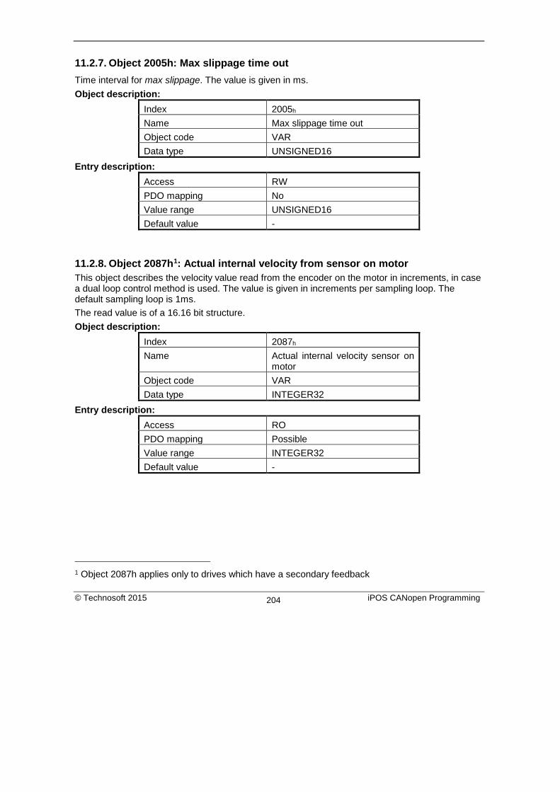
11.2.7. Object 2005h: Max slippage time out Time interval for max slippage. The value is given in ms. Object description:
Index 2005h Name Max slippage time out Object code VAR Data type UNSIGNED16
Entry description: Access RW PDO mapping No Value range UNSIGNED16 Default value -
11.2.8. Object 2087h1: Actual internal velocity from sensor on motor This object describes the velocity value read from the encoder on the motor in increments, in case a dual loop control method is used. The value is given in increments per sampling loop. The default sampling loop is 1ms. The read value is of a 16.16 bit structure. Object description:
Index 2087h Name Actual internal velocity sensor on
motor Object code VAR Data type INTEGER32
Entry description: Access RO PDO mapping Possible Value range INTEGER32 Default value -
1 Object 2087h applies only to drives which have a secondary feedback
© Technosoft 2015 iPOS CANopen Programming 204

11.3. Speed profile example Execute a speed control with 600 rpm target speed.
1. Start remote node. Send a NMT message to start the node id 6.
Send the following message:
COB-ID 0
Data 01 06
2. Ready to switch on. Change the node state from Switch on disabled to Ready to switch on by sending the shutdown command via control word associated PDO.
Send the following message:
COB-ID 206
Data 06 00
3. Switch on. Change the node state from Ready to switch on to Switch on by sending the switch on command via control word associated PDO.
Send the following message:
COB-ID 206
Data 07 00
4. Enable operation. Change the node state from Switch on to Operation enable by sending the enable operation command via control word associated PDO.
Send the following message:
COB-ID 206
Data 0F 00
5. Mode of operation. Select speed mode.
Send the following message (SDO access to object 6060h, 8-bit value 3h):
COB-ID 606
Data 2F 60 60 00 03 00 00 00
6. Target velocity. Set the target velocity to 600 rpm. By using and 500 lines incremental encoder and 1ms sample rate for position/speed control the corresponding value of object 60FFh expressed in encoder counts per sample is 140000h.
Send the following message (SDO access to object 60FFh 32-bit value 00140000h):
COB-ID 606
Data 23 FF 60 00 00 00 14 00
© Technosoft 2015 iPOS CANopen Programming 205

7. Check the motor actual speed. It should rotate with 600 rpm.
Send the following message (SDO access to read object 606Ch Velocity actual value):
COB-ID 606
Data 40 6C 60 00 00 00 00 00
© Technosoft 2015 iPOS CANopen Programming 206

12. Electronic Gearing Position (EGEAR) Mode
12.1. Overview In Electronic Gearing Position Mode the drive follows the position of an electronic gearing master with a programmable gear ratio. The electronic gearing slave can get the position information from the electronic camming master via CANbus communication channel, from another Technosoft CANopen drive set as electronic gearing master with object Master Settings (index 2010h). The position is sent using TechnoCAN, an extension of the CANopen protocol, developed by Technosoft. The online reference received via communication channel is set with object External Reference Type (index 201Dh).
The drive set as slave in electronic gearing mode performs a position control. At each slow loop sampling period, the slave computes the master position increment and multiplies it with its programmed gear ratio. The result is the slave position reference increment, which added to the previous slave position reference gives the new slave position reference.
Remark: The slave executes a relative move, which starts from its actual position
The gear ratio is specified via EGEAR multiplication factor object (index 2013h). EGEAR ratio numerator (sub-index 1) is a signed integer, while EGEAR ratio denominator (sub-index 2) is an unsigned integer. The EGEAR ratio numerator sign indicates the direction of movement: positive – same as the master, negative – reversed to the master. The result of the division between EGEAR ratio numerator and EGEAR ratio denominator is used to compute the slave reference increment.
The Master Resolution object (index 2012h) provides the master resolution, which is needed to compute correctly the master position and speed (i.e. the position increment). If master position is not cyclic (i.e. the resolution is equal with the whole 32-bit range of position), set master resolution to 0x80000001.
You can smooth the slave coupling with the master, by limiting the maximum acceleration of the slave drive. This is particularly useful when the slave has to couple with a master running at high speed, in order to minimize the shocks in the slave. The feature is activated by setting ControlWord.5=1 and the maximum acceleration value in Profile Acceleration object (index 6083h).
© Technosoft 2015 iPOS CANopen Programming 207

12.1.1. Control word in electronic gearing position mode (slave axis) MSB LSB
See 6040h Halt See
6040h Reserved Activate Acceleration Limitation
Enable Electronic Gearing Mode
See 6040h
15 9 8 7 6 5 4 3 0
Table 12.1 Control Word bits for Electronic Gearing Position Mode
Name Value Description
Enable Electronic Gearing Mode
0 Do not start operation 0 -> 1 Start electronic gearing procedure 1 Electronic gearing mode active 1 -> 0 Do nothing (does not stop current procedure)
Activate Acceleration Limitation
0 Do not limit acceleration when entering electronic gear mode 1 Limit acceleration when entering electronic gear mode to the
value set in profile acceleration (object 6083h)
Halt 0 Execute the instruction of bit 4 1 Stop drive with profile acceleration
12.1.2. Status word in electronic gearing position mode MSB LSB See 6041h Following
error Reserved See 6041h Target
reached See 6041h
15 14 13 12 11 10 9 0
Table 12.2 Status Word bits for Electronic Gearing Position Mode
Name Value Description
Target reached
0 Halt = 0: Always 0 Halt = 1: Drive decelerates
1 Halt = 0: Always 0 Halt = 1: Velocity of drive is 0
Following error
0 No following error 1 Following error occurred
© Technosoft 2015 iPOS CANopen Programming 208

12.2. Gearing Position Mode Objects
12.2.1. Object 2010h: Master settings This object contains key settings for the master of EGEAR / ECAM mode. A master in EGEAR / ECAM mode is a drive that controls a motor (irrespective of the control mode) and that will be designated to send the information about its position (demanded position or actual position) via communication to one or more slaves (programmed accordingly). This object also allows setting the address of the slave to which the master will send its position, or, if there are more slaves to receive simultaneously the position from the master, the Group ID of these slaves. Object description:
Index 2010h Name Master settings Object code VAR Data type UNSIGNED16
Entry description: Access RW PDO mapping Possible Units - Value range 0 … 65535 Default value 0
Table 12.3 Master Settings bits description
Bit Value Description 15 0 Master is not active – the master drive does not send any position values
1 Master is active – the master drive starts sending its position to the slave axis
14 10 0 Reserved
9 0 The master sends its feedback (the position actual value) 1 The master sends the demand position
8 0 Address is an axis ID 1 Address is a group ID
7 … 0 x Address of the slave drive(s)
12.2.2. Object 2012h: Master resolution This object is used in order to set the master resolution in increments per revolution. This object is valid for the slave axis.
© Technosoft 2015 iPOS CANopen Programming 209

Object description: Index 2012h Name Master resolution Object code VAR Data type UNSIGNED32
Entry description:
Access RW PDO mapping Possible Units Increments Value range 0 … 231-1 Default value 80000001h (full range)
12.2.3. Object 2013h: EGEAR multiplication factor In digital external mode, this object sets the gear ratio, or gear multiplication factor for the slaves. The sign indicates the direction of movement: positive – same as the master, negative – reversed to the master. The slave demand position is computed as the master position increment multiplied by the gear multiplication factor. Example: if the gear ratio is Slave/Master = 1/3, the following values must be set: 1 in EGEAR ratio numerator (sub-index 1) and 3 in EGEAR ratio denominator (sub-index 2) . Remark: the gear ratio is computed after sub-index 2 is written. So sub-index1 must be written first and then sub-index 2. Even if sub-index 2 has the same value as before, it must be written again for the gear ratio to be computed correctly. Object description:
Index 2013h Name EGEAR multiplication factor Object code RECORD Number of elements 2
Entry description: Sub-index 1 Description EGEAR ratio numerator (slave) Object code VAR Data type INTEGER16 Access RW PDO mapping Possible Value range -32768 … 32767
© Technosoft 2015 iPOS CANopen Programming 210

Default value 1
Sub-index 2 Description EGEAR ratio denominator
(master) Object code VAR Data type UNSIGNED16 Access RW PDO mapping Possible Value range 0 … 65535 Default value 1
12.2.4. Object 2017h: Master actual position The actual position of the master can be monitored through this object, regardless of the way the master actual position is delivered to the drive (on-line through a communication channel or from the digital inputs of the drive). The units are increments. Object description:
Index 2017h Name Master actual position Object code VAR Data type INTEGER32
Entry description: Access RO PDO mapping Possible Value range -231 … 231-1 Default value 0
12.2.5. Object 2018h: Master actual speed This object is used to inform the user of the actual value of the speed of the master, regardless of the way the master actual position is delivered to the drive (on-line through a communication channel or from the digital inputs of the drive). The units are increments / sampling. 1 IU = 1 encoder increment / sample. Object description:
Index 2018h Name Master actual speed Object code VAR Data type INTEGER16
© Technosoft 2015 iPOS CANopen Programming 211

Entry description: Access RO PDO mapping Possible Value range -32768 … 32767 Default value 0
12.2.6. Object 201Dh: External Reference Type This object is used to set the type of external reference for use with electronic gearing position, electronic camming position, position external, speed external and torque external modes. Object description:
Index 201Dh Name External Reference Type Object code VAR Data type UNSIGNED16
Entry description:
Access RW PDO mapping No Value range UNSIGNED16 Default value -
Table 12.4 External Reference Type bit description
Value Description 0 Reserved
1
On-line. In case of External Reference Position / Speed / Torque Modes, select this option in order to read the reference from the object 201C, External Online Reference In case of Electronic Gearing and Camming Position Modes, select this option in order to read the master position received from a master drive via communication
2 Analogue. In case of External Reference Position / Speed / Torque Modes, select this option in order to read the reference from the dedicated analogue input.
4 … 65535 Reserved
© Technosoft 2015 iPOS CANopen Programming 212

12.3. Electronic gearing through CAN example This example is split in two parts:
Part1: Start an electronic gearing master profile on CAN.
1. Start remote node. Send a NMT message to start the node id 7.
Send the following message:
COB-ID 0
Data 01 07
2. Ready to switch on. Change the node state from Switch on disabled to Ready to switch on by sending the shutdown command via control word associated PDO.
Send the following message:
COB-ID 207
Data 06 00
3. Switch on. Change the node state from Ready to switch on to Switch on by sending the switch on command via control word associated PDO.
Send the following message:
COB-ID 207
Data 07 00
4. Enable operation. Change the node state from Switch on to Operation enable by sending the enable operation command via control word associated PDO.
Send the following message:
COB-ID 207
Data 0F 00
5. Modes of operation. Select speed mode.
Send the following message (SDO access to object 6060h, 8-bit value 3h):
COB-ID 607
Data 2F 60 60 00 03 00 00 00
6. Target Velocity. Set speed to 15 IU.
Send the following message (SDO access to object 60FFh, 32-bit value Fh):
COB-ID 607
Data 23 FF 60 00 00 00 0F 00
The master motor should start rotating with 15IU speed.
© Technosoft 2015 iPOS CANopen Programming 213

7. Master Settings. Set the drive as master and program it to send it’s reference to axis 6.
Send the following message (SDO access to object 2010h 32-bit value 00008206h):
COB-ID 607
Data 2B 10 20 00 06 82 00 00
Part2: Start an Electronic Gearing Slave on CAN
1. Start remote node. Send a NMT message to start the node id 6.
Send the following message:
COB-ID 0
Data 01 06
2. Ready to switch on. Change the node state from Switch on disabled to Ready to switch on by sending the shutdown command via control word associated PDO.
Send the following message:
COB-ID 206
Data 06 00
3. Switch on. Change the node state from Ready to switch on to Switch on by sending the switch on command via control word associated PDO.
Send the following message:
COB-ID 206
Data 07 00
4. Enable operation. Change the node state from Switch on to Operation enable by sending the enable operation command via control word associated PDO.
Send the following message:
COB-ID 206
Data 0F 00
5. External reference type. Slave receives reference through CAN.
Send the following message (SDO access to object 201Dh):
COB-ID 606
Data 2B 1D 20 00 01 00 00 00
6. Modes of operation. Select Electronic Gearing mode.
© Technosoft 2015 iPOS CANopen Programming 214

Send the following message (SDO access to object 6060h, 8-bit value -1):
COB-ID 606
Data 2F 60 60 00 FF 00 00 00
7. Master resolution. Set the master resolution.
Send the following message (SDO access to object 6060h, 32-bit value 2000):
COB-ID 606
Data 23 12 20 00 D0 07 00 00
8. Electronic gearing multiplication factor.
Set EG numerator to 1.
Send the following message (SDO access to object 2013h,sub-index 1, 16-bit value 1):
COB-ID 606
Data 2B 13 20 01 01 00 00 00
Set EG denominator to 1.
Send the following message (SDO access to object 2013h,sub-index 2, 16-bit value 1):
COB-ID 606
Data 2B 13 20 02 01 00 00 00
9. Enable EG slave in control word associated PDO.
Send the following message:
COB-ID 206
Data 1F 00
The slave motor should start rotating with the same speed as the master motor.
© Technosoft 2015 iPOS CANopen Programming 215

13. Electronic Camming Position (ECAM) Mode
13.1. Overview In Electronic Camming Position the drive executes a cam profile function of the position of an electronic camming master. The cam profile is defined by a cam table – a set of (X, Y) points, where X is cam table input i.e. the position of the electronic camming master and Y is the cam table output i.e. the corresponding slave position. Between the points the drive performs a linear interpolation. The electronic camming slave can get the position information from the electronic camming master via CANbus communication channel, from another Technosoft drive set as electronic camming master with object Master Settings (index 2010h). The position is sent using TechnoCAN, an extension of the CANopen protocol, developed by Technosoft. The reference type is received online via communication channel and it is set with object External Reference Type (index 201Dh). The electronic camming position mode can be: relative (if ControlWord.6 = 0) or absolute (if ControlWord.6 = 1). In the relative mode, the output of the cam table is added to the slave actual position. At each slow loop sampling period the slave computes a position increment dY = Y – Yold. This is the difference between the actual cam table output Y and the previous one Yold. The position increment dY is added to the old demand position to get a new demand position. The slave detects when the master position rolls over, from 360 degrees to 0 or vice-versa and automatically compensates in dY the difference between Ymax and Ymin. Therefore, in relative mode, you can continuously run the master in one direction and the slaves will execute the cam profile once at each 360 degrees with a glitch-free transition when the cam profile is restarted. When electronic camming is activated in relative mode, the slave initializes Yold with the first cam output computed: Yold = Y = f(X). The slave will keep its position until the master starts to move and then it will execute the remaining part of the cam. For example if the master moves from X to Xmax, the slave moves with Ymax – Y. In the absolute mode, the output of the cam table Y is the demand position to reach. Remark: The absolute mode must be used with great care because it may generate abrupt variations on the slave demand position if:
Slave position is different from Y at entry in the camming mode Master rolls over and Ymax < Ymin
In the absolute mode, you can introduce a maximum speed limit to protect against accidental sudden changes of the positions to reach. The feature is activated by setting ControlWord.5=1 and the maximum speed value in object Profile Velocity (index 6081h). Typically, the cam tables are first downloaded into the EEPROM memory of the drive by the CANopen master or with EasyMotion Studio. Then using the object CAM table load address (index 2019h) they are copied in the RAM address set in object CAM table run address (index 201Ah). It is possible to copy more than one cam table in the drive/motor RAM memory. When the ECAM mode is activated it uses the CAM table found at the RAM address contained in CAM table run address.
© Technosoft 2015 iPOS CANopen Programming 216

A CAM table can be shifted, stretched or compressed.
13.1.1. Control word in electronic camming position mode MSB LSB
See 6040h Halt See 6040h
Abs / Rel Activate Speed Limitation
Enable Electronic Camming Mode
See 6040h
15 9 8 7 6 5 4 3 0
Table 13.1 Control word bits for electronic camming position mode
Name Value Description
Enable Electronic Camming Mode
0 Do not start operation 0 -> 1 Start electronic camming procedure 1 Electronic camming mode active 1 -> 0 Do nothing (does not stop current procedure)
Activate Speed Limitation
0 Do not limit speed when entering absolute electronic camming mode
1 Limit speed when entering absolute electronic camming mode at the value set in profile velocity (ONLY for absolute mode)
Abs / Rel
0 Perform relative camming mode – when entering the camming mode, the slave will compute the cam table relative to the starting moment.
1 Perform absolute camming mode – when entering the camming mode, the slave will go to the absolute position on the cam table
Halt 0 Execute the instruction of bit 4 1 Stop drive with profile acceleration
13.1.2. Status word in electronic camming position mode MSB LSB
See 6041h Following error
Reserved See 6041h
Target reached
See 6041h
15 4 13 12 11 10 9 0
© Technosoft 2015 iPOS CANopen Programming 217

Table 13.2 Status word bits for electronic camming position mode
Name Value Description
Target reached
0 Halt = 0: Always 0 Halt = 1: Drive decelerates
1 Halt = 0: Always 0 Halt = 1: Velocity of drive is 0
Following error
0 No following error 1 Following error occurred
13.2. Electronic Camming Position Mode Objects
13.2.1. Object 2019h: CAM table load address
This is the load address of the CAM table. The CAM table is stored in EEPROM memory of the drive starting from the load address. The initialization of the electronic camming mode requires the CAM table to be copied from the EEPROM memory to the RAM memory of the drive, starting from the run address, set in object 201Ah, for faster processing. The copy is made every time object 2019h is written by SDO access.
Remark: The CAM table run address object must be set before writing the object CAM table load address to assure a proper copy operation from EEPROM to RAM memory. Object description:
Index 2019h Name CAM table load address Object code VAR Data type UNSIGNED16
Entry description: Access RW PDO mapping No Units - Value range UNSIGNED16 Default value Variable depending on
motor + feedback configuration
13.2.2. Object 201Ah: CAM table run address This is the run address of the CAM table e.g. the RAM address starting from which the CAM table is copied into the RAM during initialization of the electronic camming mode. (See also 2019h).
© Technosoft 2015 iPOS CANopen Programming 218

Object description: Index 201Ah Name CAM table run address Object code VAR Data type UNSIGNED16
Entry description: Access RW PDO mapping No Units - Value range UNSIGNED16 Default value 9E00h
13.2.3. Object 201Bh: CAM offset This object may be used to shift the master position in electronic camming mode. The position actually used as X input in the cam table is not the master actual position (2017h) but (master actual position – CAM offset) computed as modulo of master resolution (2012h) The CAM offset must be set before enabling the electronic camming mode. The CAM offset is expressed in increments. Object description:
Index 201Bh Name CAM offset Object code VAR Data type UNSIGNED32
Entry description: Access RW PDO mapping No Value range 0 … 232-1 Default value 0
13.2.4. Object 206Bh: CAM: input scaling factor You can use this scaling factor in order to achieve a scaling of the input values of a CAM table. Its default value of 00010000h corresponds to a scaling factor of 1.0. Object description:
Index 206Bh Name CAM input scaling factor Object code VAR
© Technosoft 2015 iPOS CANopen Programming 219

Data type FIXED32 Entry description:
Access RW PDO mapping Possible Units - Value range FIXED32 Default value 00010000h
13.2.5. Object 206Ch: CAM: output scaling factor You can use this scaling factor in order to achieve a scaling of the output values of a CAM table. Its default value of 00010000h corresponds to a scaling factor of 1.0. Object description:
Index 206Ch Name CAM output scaling factor Object code VAR Data type FIXED32
Entry description: Access RW PDO mapping Possible Units - Value range FIXED32 Default value 00010000h
13.2.6. Building a CAM profile and saving it as an .sw file example
Build your own cam profile in any program you like.
In this example we have used MS Excell.
© Technosoft 2015 iPOS CANopen Programming 220

Figure 13.1 MS Excell interface
The numbers in the columns represent the input and output of the cam file. They are position points represented in the drive’s internal units. Let’s say that we have a 500 line quadrature encoder on the motor. This means that we will have 2000 counts per motor revolution. So the drive will rotate the rotor once if it receives a position command of 2000 internal units, or it will return 2000 internal units if the rotor turned once.
The first column represents the input position. It is a series of numbers that represent an interpolation step. Meaning that the difference between the values must be a number from the following: 20, 21, 22, 23, 24, 25, 26, 27. So let’s say that we choose interpolation step of 26 (64). The first number in the first column must be 0, the second number must be 64,the third number must be 128 and so on.
The second column represents the Output of the cam file. This number can be anything that fits in an Integer32 bit variable.
For example let’s say we have in the first column the number 640 (which is a multiple of 26) and in the second column we have the number 4000. This means that if the master is at position 640 (internal units), the slave must be at the position 4000 (internal units).
© Technosoft 2015 iPOS CANopen Programming 221

-10000
0
10000
20000
30000
40000
50000
60000
70000
0 10000 20000 30000 40000 50000 60000 70000
Figure 13.2 Cam example
After the cam is ready, save it as Text (Tab delimited) (*.txt) file.
Figure 13.3 Save As example.
© Technosoft 2015 iPOS CANopen Programming 222

Once you have your cam file saved, start EasyMotion Studio, even the demo1 version.
Press New button and select your drive type.
Figure 13.4 Choose drive configuration.
After the project opens, select CAM Tables tab from the left of the screen. Press the import button and choose your recently saved cam file (see Figure 13.5).
1 ESM demo version available in download section here.
© Technosoft 2015 iPOS CANopen Programming 223
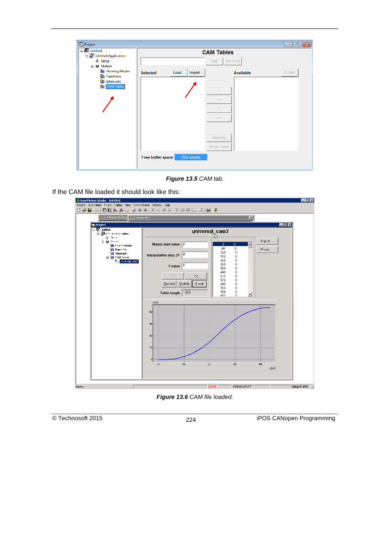
Figure 13.5 CAM tab.
If the CAM file loaded it should look like this:
Figure 13.6 CAM file loaded.
© Technosoft 2015 iPOS CANopen Programming 224

After loading the CAM file successfully, click over the Setup tab and load your saved setup1.
Click the tab with the name of the application . Press the memory settings button (like in the figure below).
Figure 13.7 Memory Settings location.
In the window below see if necessary CAM space is larger than reserved cam space. If it is, write a slightly larger number than the necessary CAM space in the reserved one (Figure below).
Figure 13.8 Adjusting the necessary CAM space.
In Memory Settings window look inside EEPROM memory section under CAM Tables. The first number is the cam table Load Address which must be set also in object 2019h afterwards.
1 To create a setup file, please check your drive’s user manual.
© Technosoft 2015 iPOS CANopen Programming 225

Figure 13.9 Cam table load and run addresses.
Under the RAM memory section the fist number in CAM Tables is the cam table Run Address which must also be set in object 201Ah afterwards. Save the project and select Application -> Create EEPROM programmer file -> Motion and Setup… like in the figure below. Save the eeprom file that includes your setup and motion (including CAM data) onto your PC.
Figure 13.10 Create .sw file.
© Technosoft 2015 iPOS CANopen Programming 226

13.2.6.1. Extracting the cam data from the motion and setup .sw file
Open the recently saved .sw file with any text editor. Inside the .sw file search for the number that corresponds to the CAM Table load address. This number shall be delimited by an empty new line just before it (Figure 12.11) (the numbers before it represent the setup data). Select all these numbers that represent the cam file until you find another empty new line (Figure 12.12).
Figure 13.11 .sw file structure example
Figure 13.12 .sw file empty line
© Technosoft 2015 iPOS CANopen Programming 227

Copy all these numbers and save them as a new text file with the extension .sw instead of .txt. Now you have a file that can be loaded onto the drive either with THS EEPROM Programmer (supplied free with EasySetup or ESM) or load it with the help of 2064h 2065h objects explained in next sub chapter.
Figure 13.13 THS EEPROM Programmer.
Note: with THS EEPROM programmer you can write the entire setup and motion .sw file, not just the CAM .sw file created in this example.
13.2.6.2. Downloading a CAM .sw file with objects 2064h and 2065h example
In order to download the data block pointed by the red arrow found in Figure 11.11, first the block start address i.e. 5638h must be set using an SDO access to object 2064h :
COB-ID 60A
Data 23 64 20 00 08 00 38 56 The above configuration command also indicates that the next read or write operation shall be executed with drive’s EEPROM memory using 16-bit data and auto increment of address. All the numbers from the lines after 5638h until the following blank line represent data to write in the EEPROM memory at consecutive addresses starting with 5638h. The data writes are done using an SDO access to object 2065h. First data word C400h is written using:
COB-ID 60A
Data 23 65 20 00 00 C4 00 00 Next data word 0000h is written with:
© Technosoft 2015 iPOS CANopen Programming 228
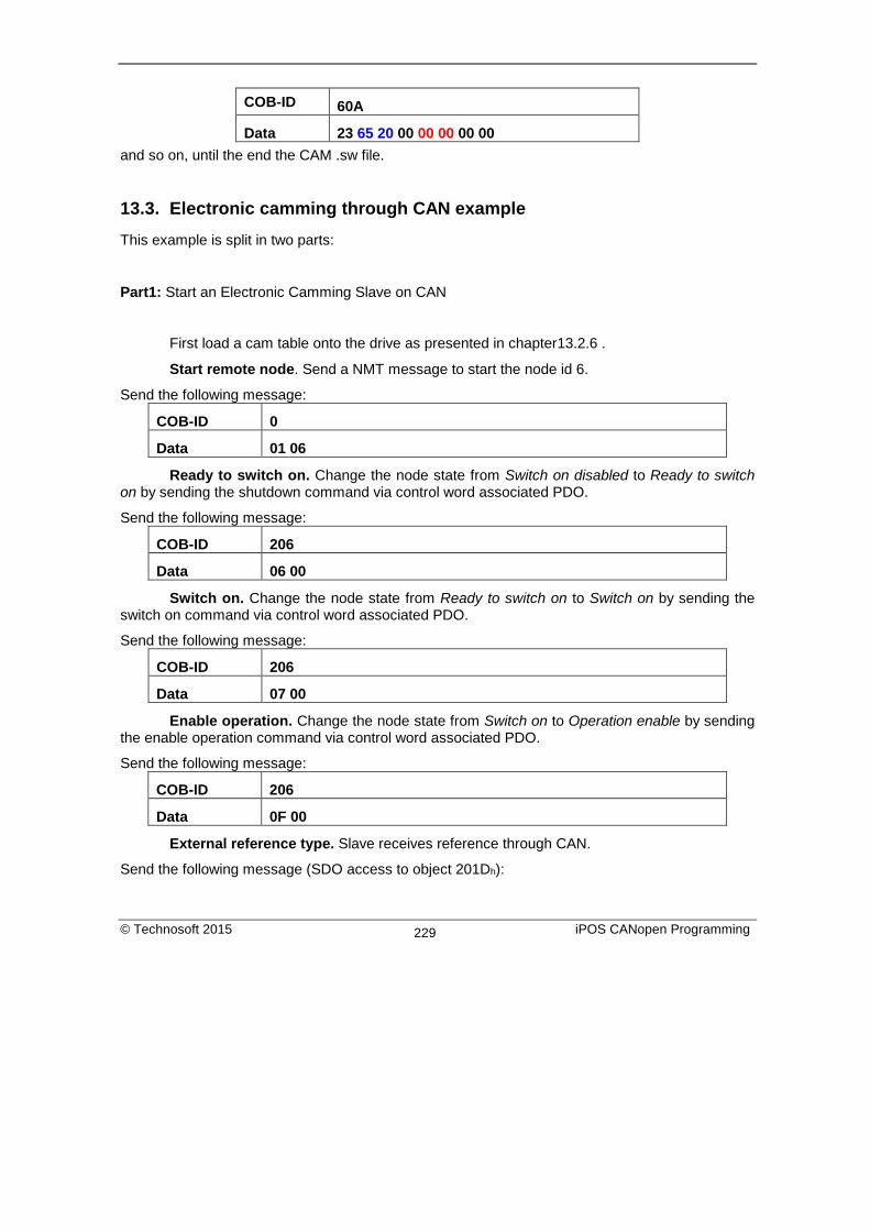
COB-ID 60A
Data 23 65 20 00 00 00 00 00 and so on, until the end the CAM .sw file.
13.3. Electronic camming through CAN example This example is split in two parts:
Part1: Start an Electronic Camming Slave on CAN
First load a cam table onto the drive as presented in chapter13.2.6 .
Start remote node. Send a NMT message to start the node id 6.
Send the following message:
COB-ID 0
Data 01 06
Ready to switch on. Change the node state from Switch on disabled to Ready to switch on by sending the shutdown command via control word associated PDO.
Send the following message:
COB-ID 206
Data 06 00
Switch on. Change the node state from Ready to switch on to Switch on by sending the switch on command via control word associated PDO.
Send the following message:
COB-ID 206
Data 07 00
Enable operation. Change the node state from Switch on to Operation enable by sending the enable operation command via control word associated PDO.
Send the following message:
COB-ID 206
Data 0F 00
External reference type. Slave receives reference through CAN.
Send the following message (SDO access to object 201Dh):
© Technosoft 2015 iPOS CANopen Programming 229

COB-ID 606
Data 2B 1D 20 00 01 00 00 00
Cam table load address. Set cam table load address as 5638h.
The cam table load address can be discovered as explained in chapter13.2.6 .
Send the following message (SDO access to object 2019h):
COB-ID 606
Data 2B 19 20 00 1E 5A 00 00
Cam table run address. Set cam table load address as 97F6h.
The cam table run address can be discovered as explained in chapter 13.2.6 .
Send the following message (SDO access to object 201Ah):
COB-ID 606
Data 2B 1A 20 00 F6 97 00 00
Modes of operation. Select Electronic Camming mode.
Send the following message (SDO access to object 6060h, 8-bit value -2):
COB-ID 606
Data 2F 60 60 00 FE 00 00 00
Master resolution. Set the master resolution.
Send the following message (SDO access to object 2012h, 32-bit value 2000):
COB-ID 606
Data 23 12 20 00 D0 07 00 00
Cam offset. Set cam offset to 6000 counts (1770h).
If the master resolution is 2000 counts/revolution, the slave shall start applying the cam when the master is at position 6000 + CamX value.
Send the following message (SDO access to object 201Bh, 32-bit value 1770h):
COB-ID 606
Data 23 1B 20 00 70 17 00 00
Cam input scaling factor. Set it to 1.
Send the following message (SDO access to object 206Bh, 32-bit value 1):
COB-ID 606
Data 23 6B 20 00 00 00 01 00
© Technosoft 2015 iPOS CANopen Programming 230

Cam output scaling factor. Set it to 1.
Send the following message (SDO access to object 206Ch, 32-bit value 1):
COB-ID 606
Data 23 6C 20 00 00 00 01 00
Enable ECam slave mode in control word associated PDO.
Send the following message:
COB-ID 206
Data 3F 00
The slave shall start moving and applying the cam after the master starts.
Part2: Start an electronic camming master on CAN.
1. Start remote node. Send a NMT message to start the node id 7.
Send the following message:
COB-ID 0
Data 01 07
2. Ready to switch on. Change the node state from Switch on disabled to Ready to switch on by sending the shutdown command via control word associated PDO.
Send the following message:
COB-ID 207
Data 06 00
3. Switch on. Change the node state from Ready to switch on to Switch on by sending the switch on command via control word associated PDO.
Send the following message:
COB-ID 207
Data 07 00
4. Enable operation. Change the node state from Switch on to Operation enable by sending the enable operation command via control word associated PDO.
Send the following message:
COB-ID 207
Data 0F 00
5. Modes of operation. Select speed mode.
© Technosoft 2015 iPOS CANopen Programming 231

Send the following message (SDO access to object 6060h, 8-bit value 3h):
COB-ID 607
Data 2F 60 60 00 03 00 00 00
6. Target Velocity. Set speed to 15 IU.
Send the following message (SDO access to object 60FFh, 32-bit value Fh):
COB-ID 607
Data 23 FF 60 00 00 00 0F 00
The master motor should start rotating with 15IU speed.
7. Master Settings. Set the drive as master and program it to send it’s reference to axis 6.
Send the following message (SDO access to object 607Ah 32-bit value 00002710h):
COB-ID 607
Data 2B 10 20 00 06 80 00 00
After the master is at position 6000 IU (cam offset), the slave (axis 06) shall rotate depending on the set cam values.
© Technosoft 2015 iPOS CANopen Programming 232

14. External Reference Position Mode
14.1. Overview In this operating mode the drive performs position control with the demand position read from the external reference provided by another device.
There are 2 types of external references:
Analogue – read by the drive via a dedicated analogue input (12-bit resolution) Online – received online via the CAN bus communication channel from the CANopen master in object External On-line Reference (index 201Ch)
The reference type is selected with object External Reference Type (index 201Dh).
In external reference position mode with analogue or online reference, you can limit the maximum speed at sudden changes of the position reference and thus to reduce the mechanical shocks. This feature is activated by setting ControlWord.6=1 and the maximum speed value in object Profile Velocity (index 6081h).
14.1.1. Control word in external reference position mode MSB LSB
See 6040h Halt See 6040h
Reserved Activate Speed Limitation
Enable External Position Mode
See 6040h
15 9 8 7 6 5 4 3 0
Table 14.1 Control Word bit description for External Reference Position mode
Name Value Description
Enable External Position Mode 0 External position mode inactive 1 External position mode active
Activate Speed Limitation 0 Do not limit speed on the inactive to active mode
transition
1 Limit speed when enabling the External Position mode
Halt 0 Execute the instruction of bit 4 1 Stop drive with profile acceleration
In order to correctly set an external reference position mode, you have to set the way the reference is received (either on-line or analogue), using the object 201Dh, External Reference Type.
© Technosoft 2015 iPOS CANopen Programming 233

14.1.2. Status word in external reference position mode MSB LSB
See 6041h Following error
Reserved See 6041h
Target reached
See 6041h
15 14 13 12 11 10 9 0
Table 14.2 Status Word bit description for External Reference Position mode
Name Value Description
Target reached
0 Halt = 0: Always 0 Halt = 1: Drive decelerates
1 Halt = 0: Always 0 Halt = 1: Velocity of drive is 0
Following error
0 No following error 1 Following error occurred
14.2. External Reference Position Mode Objects
14.2.1. Object 201Ch: External On-line Reference This is used to set the reference in case the External Reference Type (Object 201Dh) is set for online. The unit for this object is the internal unit defined for each drive mode (position / speed / torque). Object description:
Index 201Ch Name External online reference Object code VAR Data type INTEGER32
Entry description: Access RW PDO mapping Possible Units Internal, operating mode
dependant Value range INTEGER32 Default value 0
© Technosoft 2015 iPOS CANopen Programming 234

15. External Reference Speed Mode
15.1. Overview In this mode, the drive performs speed control with demand velocity read from the external reference provided by other devices.
There are 2 types of external references:
Analogue – read by the drive via a dedicated analogue input (12-bit resolution) Online – received online via the CAN bus communication channel from the CANopen master in object External On-line Reference (index 201Ch)
The reference type is selected with object External Reference Type (index 201Dh).
In external reference speed mode, you can limit the maximum acceleration at sudden changes of the speed reference and thus to get a smoother transition. This feature is activated by setting ControlWord.5=1 and the maximum acceleration value in object Profile Acceleration (6083h).
15.1.1. Control word in external reference speed mode MSB LSB
See 6040h Halt See 6040h
Reserved Activate Acceleration Limitation
Enable External Speed Mode
See 6040h
15 9 8 7 6 5 4 3 0
Table 15.1 Control Word bit description for External Reference Speed Mode
Name Value Description Enable External Speed Mode
0 External speed mode inactive 1 External speed mode active
Activate Speed Limitation
0 Do not limit acceleration on the inactive to active mode transition
1 Limit acceleration when enabling the External Speed mode Halt 0 Execute the instruction of bit 4
1 Stop drive with profile acceleration
15.1.2. Status word in external reference speed mode MSB LSB
See 6041h Max slippage error
Speed See 6041h
Target reached
See 6041h
15 14 13 12 11 10 9 0
© Technosoft 2015 iPOS CANopen Programming 235

Table 15.2 Status Word bit description for External Reference Speed Mode
Name Value Description
Target reached
0 Halt = 0: Always 0 Halt = 1: Drive decelerates
1 Halt = 0: Always 0 Halt = 1: Velocity of drive is 0
Speed 0 Speed is not equal to 0 1 Speed is equal to 0
Max slippage error
0 Maximum slippage not reached 1 Maximum slippage reached
Remark: In order to set / reset bit 12, the object from index 606Fh, velocity threshold from profile velocity mode will be used. If the actual velocity of the drive / motor is below the velocity threshold, then bit 12 will be set, else it will be reset.
© Technosoft 2015 iPOS CANopen Programming 236
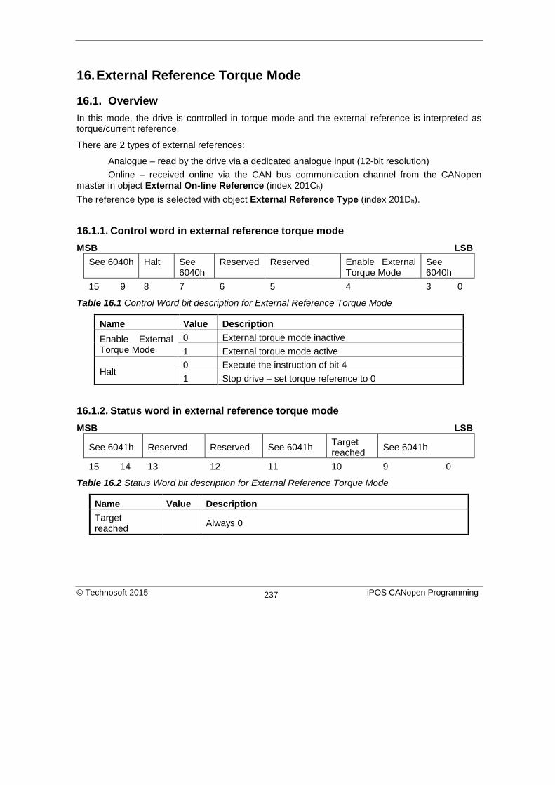
16. External Reference Torque Mode
16.1. Overview In this mode, the drive is controlled in torque mode and the external reference is interpreted as torque/current reference.
There are 2 types of external references:
Analogue – read by the drive via a dedicated analogue input (12-bit resolution) Online – received online via the CAN bus communication channel from the CANopen master in object External On-line Reference (index 201Ch) The reference type is selected with object External Reference Type (index 201Dh).
16.1.1. Control word in external reference torque mode MSB LSB
See 6040h Halt See 6040h
Reserved Reserved Enable External Torque Mode
See 6040h
15 9 8 7 6 5 4 3 0
Table 16.1 Control Word bit description for External Reference Torque Mode
Name Value Description Enable External Torque Mode
0 External torque mode inactive 1 External torque mode active
Halt 0 Execute the instruction of bit 4 1 Stop drive – set torque reference to 0
16.1.2. Status word in external reference torque mode MSB LSB
See 6041h Reserved Reserved See 6041h Target reached See 6041h
15 14 13 12 11 10 9 0
Table 16.2 Status Word bit description for External Reference Torque Mode
Name Value Description Target reached
Always 0
© Technosoft 2015 iPOS CANopen Programming 237

16.2. External reference torque mode objects
16.2.1. Object 6071h: Target torque1 This is used to indicate the configured input value for the torque controller in profile torque mode. The unit for this object is given in IU. Object description:
Index 6071h Name Target torque Object code VAR Data type INTEGER16
Entry description: Access RW PDO mapping Yes Value range UNSIGNED16 Default value 0000h
The computation formula for the current [IU] in [A] is:
IpeakAcurrentIUcurent
⋅⋅
=2
][65520][
where Ipeak is the peak current supported by the drive and current[IU] is the command value for object 6071h.
16.2.2. Object 6077h: Torque actual value2 This is used to provide the actual value of the torque. It corresponds to the instantaneous torque in the motor. The value is given in IU. Object description:
Index 6077h Name Torque actual value Object code VAR Data type INTEGER16
Entry description: Access RO PDO mapping Yes
1 Available only on firmware F514x 2 Available only on firmware F514x
© Technosoft 2015 iPOS CANopen Programming 238

Value range UNSIGNED16 Default value No
The computation formula for the current [IU] in [A] is:
][65520
2][ IUcurentIpeakAcurrent ⋅⋅
=
where Ipeak is the peak current supported by the drive and current[IU] is the read value from object 6077h.
16.2.3. Object 207Eh: Current actual value1 The object displays the motor current actual value. This value is given in current internal units. Object description:
Index 207Eh Name Current actual value Object code VAR Data type Integer16
Entry description: Access RO PDO mapping YES Units - Value range -32768 … 32767 Default value No
The computation formula for the current [IU] in [A] is:
][65520
2][ IUcurentIpeakAcurrent ⋅⋅
=
where Ipeak is the peak current supported by the drive and current[IU] is the read value from object 207Eh.
1 Available only with firmwares F508I/F509I and above.
© Technosoft 2015 iPOS CANopen Programming 239

17. Touch probe functionality1
17.1. Overview The Touch probe functionality offers the possibility to capture the motor current position when a configurable digital input trigger event happens.
Remark: do not use the touch probe functionality objects during a homing procedure. It may lead to incorrect results.
17.2. Touch probe objects
17.2.1. Object 60B8h: Touch probe function This object indicates the configuration function of the touch probe.
Object description:
Index 60B8h
Name Touch probe function
Object code VAR
Data type UNSIGNED16
Entry description:
Access RW
PDO mapping Yes
Value range 0 … 65535
Default value 0
The Touch probe function has the following bit assignment:
1 This feature is available since firmware revision F
© Technosoft 2015 iPOS CANopen Programming 240

Table 17.1 Bit Assignment of the Touch probe function
Bit Value Description 14,15 - Reserved
13 0 Switch off sampling at negative edge of touch probe 2
1 Enable sampling at negative edge of touch probe 2*
12 0 Switch off sampling at positive edge of touch probe 2
1 Enable sampling at positive edge of touch probe 2*
11,10
00b Trigger with touch probe 2 input (LSN input)
01b Trigger with zero impulse signal
10b Reserved
11b Reserved
9 0 Trigger first event
1 Reserved
8 0 Switch off touch probe 2
1 Enable touch probe 2
7 - Reserved
6 0 Enable limit switch functionality. The motor will stop, using quickstop
d l ti h li it it h i ti 1 Disable limit switch functionality. The motor will not stop when a limit i h i i
5 0 Switch off sampling at negative edge of touch probe 1
1 Enable sampling at negative edge of touch probe 1*
4 0 Switch off sampling at positive edge of touch probe 1
1 Enable sampling at positive edge of touch probe 1*
3,2
00b Trigger with touch probe 1 input (LSP input)
01b Trigger with zero impulse signal
10b Reserved
11b Reserved
1 0 Trigger first event
1 Reserved
0 0 Switch off touch probe 1
1 Enable touch probe 1
© Technosoft 2015 iPOS CANopen Programming 241
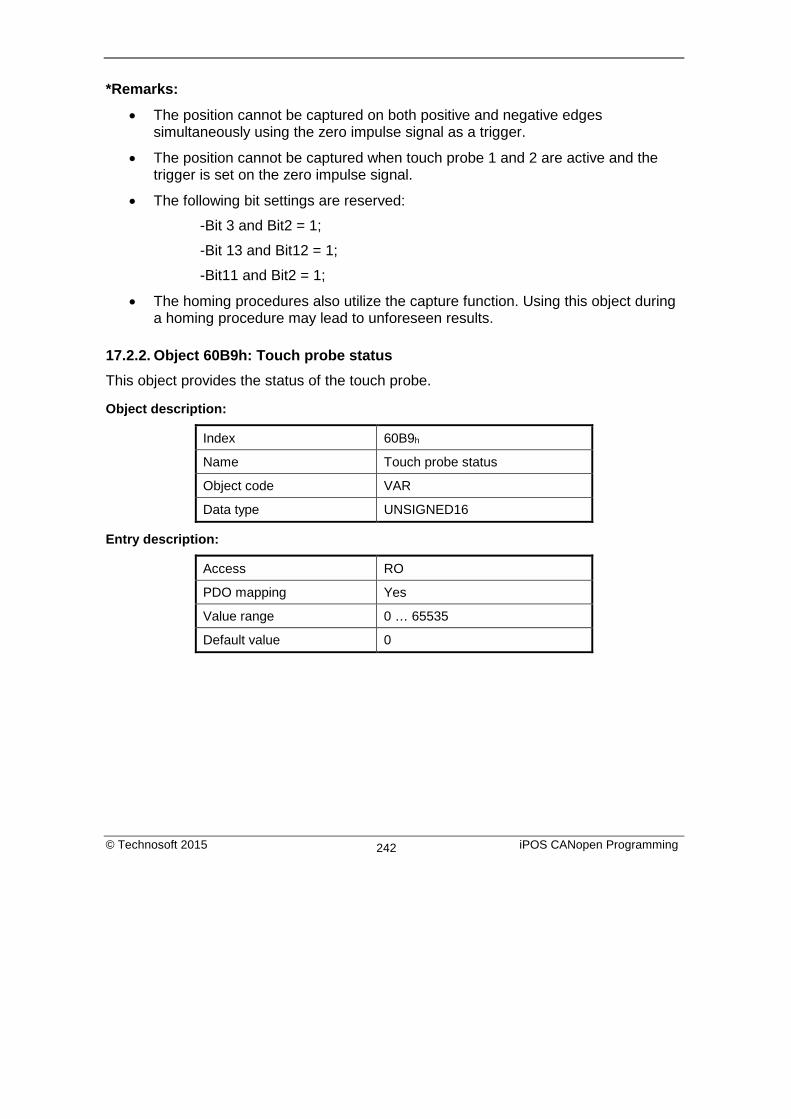
*Remarks:
• The position cannot be captured on both positive and negative edges simultaneously using the zero impulse signal as a trigger.
• The position cannot be captured when touch probe 1 and 2 are active and the trigger is set on the zero impulse signal.
• The following bit settings are reserved:
-Bit 3 and Bit2 = 1;
-Bit 13 and Bit12 = 1;
-Bit11 and Bit2 = 1;
• The homing procedures also utilize the capture function. Using this object during a homing procedure may lead to unforeseen results.
17.2.2. Object 60B9h: Touch probe status This object provides the status of the touch probe.
Object description:
Index 60B9h
Name Touch probe status
Object code VAR
Data type UNSIGNED16
Entry description:
Access RO
PDO mapping Yes
Value range 0 … 65535
Default value 0
© Technosoft 2015 iPOS CANopen Programming 242

The Touch probe status has the following bit assignment:
Table 17.2 Bit Assignment of the Touch probe status
Bit Value Description
11 to 15 - Reserved
10 0 Touch probe 2 no negative edge value stored
1 Touch probe 2 negative edge position stored in object 60BDh
9 0 Touch probe 2 no positive edge value stored
1 Touch probe 2 positive edge position stored in object 60BCh
8 0 Touch probe 2 is switched off
1 Touch probe 2 is enabled
7 - Reserved
6 0 Limit switch functionality enabled.
1 Limit switch functionality disabled.
3 to 5 - Reserved
2 0 Touch probe 1 no negative edge value stored
1 Touch probe 1 negative edge position stored in object 60BBh
1 0 Touch probe 1 no positive edge value stored
1 Touch probe 1 positive edge position stored in object 60BAh
0 0 Touch probe 1 is switched off
1 Touch probe 1 is enabled
Note: Bit 1 and bit 2 are set to 0 when touch probe 1 is switched off (object 60B8h bit 0 is 0). Bit 9 and 10 are set to 0 when touch probe 2 is switched off (object 60B8h bit 8 is 0). Bits 1,2,9 and 10 are set to 0 when object 60B8h bits 4,5,12 and 13 are set to 0.
17.2.3. Object 60BAh: Touch probe 1 positive edge This object provides the position value of the touch probe 1 at positive edge. Object description:
Index 60BAh Name Touch probe 1 positive edge
© Technosoft 2015 iPOS CANopen Programming 243

Object code VAR Data type INTEGER32
Entry description: Access RO PDO mapping YES Value range -231…231-1 Default value -
17.2.4. Object 60BBh: Touch probe 1 negative edge This object provides the position value of the touch probe 1 at negative edge. Object description:
Index 60BBh Name Touch probe 1 negative edge Object code VAR Data type INTEGER32
Entry description: Access RO PDO mapping YES Value range -231…231-1 Default value -
17.2.5. Object 60BCh: Touch probe 2 positive edge This object provides the position value of the touch probe 2 at positive edge. Object description:
Index 60BCh Name Touch probe 2 positive edge Object code VAR Data type INTEGER32
Entry description: Access RO PDO mapping YES Value range -231…231-1 Default value -
© Technosoft 2015 iPOS CANopen Programming 244

17.2.6. Object 60BDh: Touch probe 2 negative edge This object provides the position value of the touch probe 2 at negative edge. Object description:
Index 60BDh Name Touch probe 2 negative edge Object code VAR Data type INTEGER32
Entry description: Access RO PDO mapping YES Value range -231…231-1 Default value -
17.2.7. Object 2104h1: Auxiliary encoder function This object configures the auxiliary feedback position capture on the zero impulse signal.
Object description:
Index 2104h
Name Auxiliary encoder function
Object code VAR
Data type UNSIGNED16
Entry description:
Access RW
PDO mapping Yes
Value range 0 … 65535
Default value 0
The auxiliary feedback touch probe function has the following bit assignment:
1 Object 2104h applies only to drives which have a secondary feedback input with an index signal
© Technosoft 2015 iPOS CANopen Programming 245

Table 17.3 Bit Assignment of the Auxiliary encoder function
Bit Value Description
15..6 - Reserved
5 0 Switch off sampling at negative edge of touch probe
1* Enable sampling at negative edge of touch probe
4 0 Switch off sampling at positive edge of touch probe
1* Enable sampling at positive edge of touch probe
3 - Reserved
2 0 Reserved
1 Trigger with zero impulse signal
1 - Reserved
0 0 Switch off touch probe
1 Enable touch probe
*Remark The position cannot be captured on both positive and negative edges simultaneously using the zero impulse signal as a trigger.
17.2.8. Object 2105h1: Auxiliary encoder status This object provides the status of the auxiliary feedback touch probe.
Object description:
Index 2105h
Name Auxiliary encoder status
Object code VAR
Data type UNSIGNED16
Entry description:
Access RO
PDO mapping Yes
1 Object 2105h applies only to drives which have a secondary feedback input with an index signal
© Technosoft 2015 iPOS CANopen Programming 246

Value range 0 … 65535
Default value 0
The auxiliary feedback touch probe status has the following bit assignment:
Table 17.4 Bit Assignment of the Auxiliary encoder status
Bit Value Description
15 to 3 - Reserved
2 0 Auxiliary feedback touch probe no negative edge value stored
1 Auxiliary feedback touch probe negative edge position stored in object 2107h
1 0 Auxiliary feedback touch probe no positive edge value stored
1 Auxiliary feedback touch probe positive edge position stored in object 2106h
0 0 Auxiliary feedback touch probe is switched off
1 Auxiliary feedback touch probe is enabled
Note: Bit 1 and bit 2 are set to 0 when auxiliary feedback touch probe is switched off (object 2104h bit 0 is 0). Bits 1 and 2 are set to 0 when object 2104h bits 4 and 5 are set to 0.
17.2.9. Object 2106h1: Auxiliary encoder captured position positive edge This object provides the position value of the auxiliary feedback captured at positive edge. Object description:
Index 2106h Name Auxiliary encoder captured
positive edge Object code VAR Data type INTEGER32
Entry description: Access RO
1 Object 2106h applies only to drives which have a secondary feedback input with an index signal
© Technosoft 2015 iPOS CANopen Programming 247

PDO mapping YES Value range -231…231-1 Default value -
17.2.10. Object 2107h1: Auxiliary encoder captured position negative edge This object provides the position value of the auxiliary feedback captured at negative edge. Object description:
Index 2107h Name Auxiliary encoder captured
position negative edge Object code VAR Data type INTEGER32
Entry description: Access RO PDO mapping YES Value range -231…231-1 Default value -
1 Object 2107h applies only to drives which have a secondary feedback input with an index signal
© Technosoft 2015 iPOS CANopen Programming 248

18. Data Exchange between CANopen master and drives
18.1. Checking Setup Data Consistency During the configuration phase, a CANopen master can quickly verify using the checksum objects and a reference .sw file whether the non-volatile EEPROM memory of the iPOS drive contains the right information. If the checksum reported by the drive doesn’t match the one computed from the .sw file, the CANopen master can download the entire .sw file into the drive EEPROM using the communication objects for writing data into the drive EEPROM. In order to be able to inspect or to program any memory location of the drive, as well as for downloading of a new TML program (application software), three manufacturer specific objects were defined: Object 2064h – Read/Write Configuration Register, 2065h – Write Data at address specified in 2064h, 2066h – Read Data from address specified in 2064h, 2067h – Write data at specified address.
18.2. Image Files Format and Creation
An image file (with extension .sw) is a text file that can be read with any text editor. It contains blocks of data separated by an empty line. Each block of data starts with the block start address, followed by data values to place in ascending order at consecutive addresses: first data – to write at start address, second data – to write at start address + 1, etc. All the data are hexadecimal 16- bit values (maximum 4 hexadecimal digits). Each line contains a single data value. When less then 4 hexadecimal digits are shown, the value must be right justified. For example 92 represent 0x0092.
The .sw software files can be generated either from EasySetUp or from EasyMotion Studio.
In EasySetUp you create a .sw file with the command Setup | EEPROM Programmer File… The software file generated, includes the setup data and the drive/motor configuration ID with the user programmable application ID.
In EasyMotion Studio you create a .sw file with one of the commands: Application | EEPROM Programmer File | Motion and Setup or Setup Only. The option Motion and Setup creates a .sw file with complete information including setup data, TML programs, cam tables (if present) and the drive/motor configuration ID. The option Setup Only produces a .sw file identical with that produced by EasySetUp i.e. having only the setup data and the configuration ID.
The .sw file can be programmed into a drive:
from a CANopen master, using the communication objects for writing data into the drive EEPROM using the EEPROM Programmer tool, which comes with EasySetUp but may also be installed separately. The EEPROM Programmer was specifically designed for repetitive fast and easy programming of .sw files into the Technosoft drives during production.
© Technosoft 2015 iPOS CANopen Programming 249
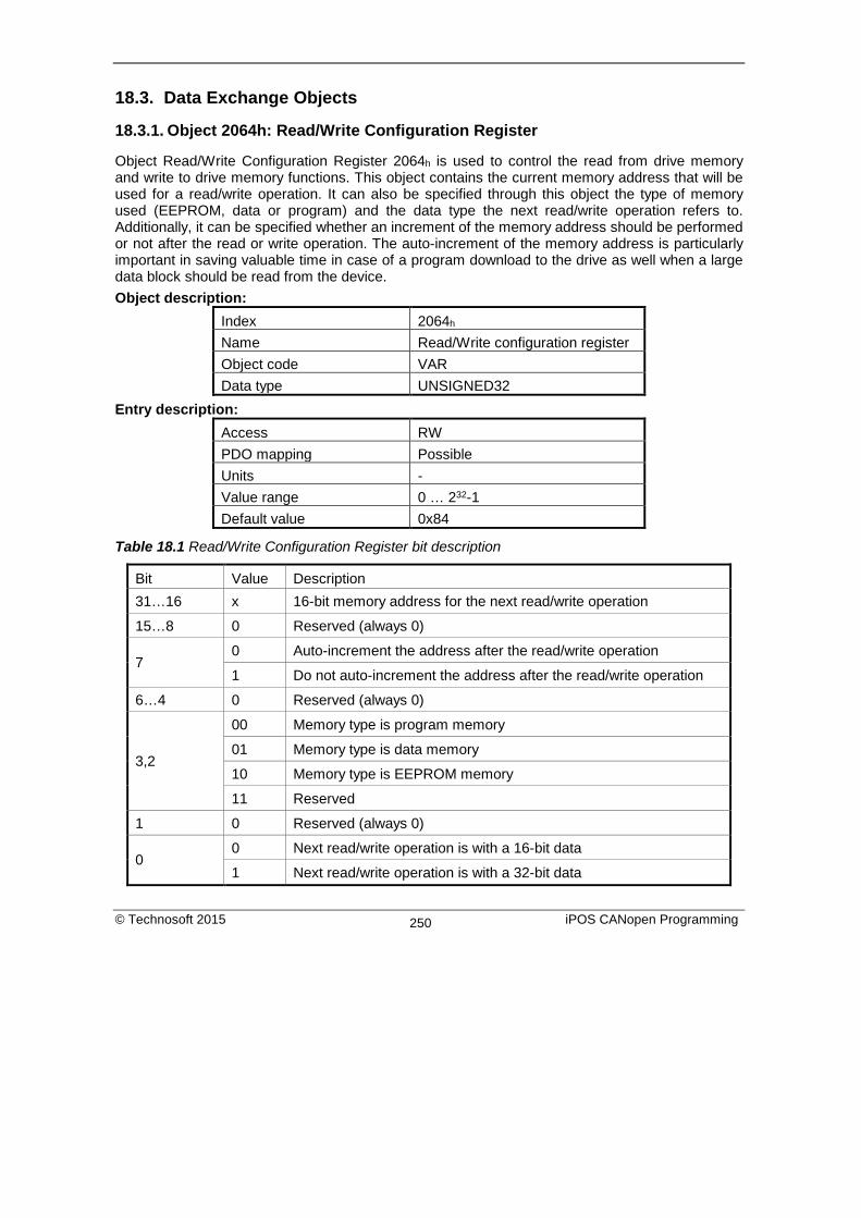
18.3. Data Exchange Objects
18.3.1. Object 2064h: Read/Write Configuration Register
Object Read/Write Configuration Register 2064h is used to control the read from drive memory and write to drive memory functions. This object contains the current memory address that will be used for a read/write operation. It can also be specified through this object the type of memory used (EEPROM, data or program) and the data type the next read/write operation refers to. Additionally, it can be specified whether an increment of the memory address should be performed or not after the read or write operation. The auto-increment of the memory address is particularly important in saving valuable time in case of a program download to the drive as well when a large data block should be read from the device. Object description:
Index 2064h Name Read/Write configuration register Object code VAR Data type UNSIGNED32
Entry description: Access RW PDO mapping Possible Units - Value range 0 … 232-1 Default value 0x84
Table 18.1 Read/Write Configuration Register bit description
Bit Value Description 31…16 x 16-bit memory address for the next read/write operation
15…8 0 Reserved (always 0)
7 0 Auto-increment the address after the read/write operation
1 Do not auto-increment the address after the read/write operation
6…4 0 Reserved (always 0)
3,2
00 Memory type is program memory
01 Memory type is data memory
10 Memory type is EEPROM memory
11 Reserved
1 0 Reserved (always 0)
0 0 Next read/write operation is with a 16-bit data
1 Next read/write operation is with a 32-bit data
© Technosoft 2015 iPOS CANopen Programming 250

18.3.2. Object 2065h: Write 16/32 bits data at address set in Read/Write Configuration Register
The object is used to write 16 or 32-bit values using the parameters specified in object 2064h – Read/Write Configuration Register. After the successful write operation, the memory address in object 2064h, bits 31…16 will be auto-incremented or not, as defined in the same register. The auto-incrementing of the address is particularly useful in downloading a program (software application) in the drives memory. Object description:
Index 2065h Name Write data at address set in 2064h
(16/32 bits) Object code VAR Data type UNSIGNED32
Entry description: Access WO PDO mapping Possible Units - Value range 0 … 232-1 Default value No
The structure of the parameter is the following:
Bit Value Description
31…16 0 Reserved if bit 0 of object 2064h is 0 (operation on 16 bit variables)
X 16-bit MSB of data if bit 0 of object 2064h is 1 (operation on 32 bit variables)
15…0 X 16 bit LSB of data
18.3.3. Object 2066h: Read 16/32 bits data from address set in Read/Write Configuration Register
This object is used to read 16 or 32-bit values with parameters that are specified in object 2064h – Read/Write Configuration Register. After the successful read operation, the memory address in object 2064h, bits 31…16, will be auto-incremented or not, as defined in the same register. Object description:
Index 2066h
Name Read data from address set in 2064h (16/32 bits)
Object code VAR
© Technosoft 2015 iPOS CANopen Programming 251

Data type UNSIGNED32 Entry description:
Access RO PDO mapping No Units - Value range UNSIGNED32 Default value No
The structure of the parameter is the following:
Bit Value Description
31…16 0 Reserved if bit 0 of object 2064h is 0 (operation on 16 bit variables)
X 16-bit MSB of data if bit 0 of object 2064h is 1 (operation on 32 bit variables)
15…0 X 16 bit LSB of data
18.3.4. Object 2067h: Write data at specified address This object is used to write a single 16-bit value at a specified address in the memory type defined in object 2064h – Read/Write Configuration Register. The rest of the bits in object 2064h do not count in this case, e.g. the memory address stored in the Read/Write Control Register is disregarded and also the control bits 0 and 7. The object may be used to write only 16-bit data. Once the type of memory in the Read/Write Control Register is set, the object can be used independently. If mapped on a PDO, it offers quick access to any drive internal variable. Object description:
Index 2067h Name Write data at specified address Object code VAR Data type UNSIGNED32
Entry description: Access WO PDO mapping Possible Units - Value range UNSIGNED32 Default value No
Bit Value Description 31…16 x 16-bit memory address 15…0 X 16 bit data value to be written
© Technosoft 2015 iPOS CANopen Programming 252

18.3.5. Object 2069h: Checksum configuration register This object is used to specify a start address and an end address for the drive to execute a checksum of the E2ROM memory contents. The 16 LSB of this object are used for the start address of the checksum, and the 16 MSB for the end address of the checksum. Note: The end address of the checksum must be computed as the start address to which you add the length of the section to be checked. The drive will actually compute the checksum for the memory locations between start address and end address. The checksum is computed as a 16 bit unsigned addition of the values in the memory locations to be checked. When the object is written through SDO access, the checksum will be computed and stored in the read-only object 206Ah. Object description:
Index 2069h Name Checksum configuration register Object code VAR Data type UNSIGNED32
Entry description: Access RW PDO mapping No Units - Value range UNSIGNED32 Default value No
The structure of the parameter is the following:
Bit Value Description 31…16 X 16-bit end address of the checksum 15…0 X 16 bit start address of the checksum
18.3.6. Object 206Ah: Checksum read register This object stores the latest computed checksum. Object description:
Index 206Ah Name Checksum read register Object code VAR Data type UNSIGNED16
Entry description: Access RO
© Technosoft 2015 iPOS CANopen Programming 253

PDO mapping No Units - Value range UNSIGNED16 Default value No
18.4. Downloading an image file (.sw) to the drive using CANopen objects example
The structure of an image file (.sw) is described in paragraph 18.2 and shown in Figure 18.1.
In order to download the data block pointed by the red arrow, first the block start address i.e. 5638h must be set using an SDO access to object 2064h.
• Send the following message: SDO access to object 2064h, 32-bit value 56380008h.
The above configuration command also indicates that next read or write operation shall be executed with drive’s EEPROM memory using 16-bit data and auto increment of address. All the numbers from the lines after 5638h until the following blank line represents data to write in the EEPROM memory at consecutive addresses starting with 5638h. The data writes are done using an SDO access to object 2065h. First data word C400h is written using:
• Send the following message: SDO access to object 2065h, 32-bit value 0000C400h.
From the whole 32bit number, only C400h will be written and 0000h will be ignored because the write operation was configured for 16bits in object 2065 h.
Next data word 0000h is written with:
• Send the following message: SDO access to object 2065h, 32-bit value 00000000h.
Figure 18.1 .sw file structure
example
© Technosoft 2015 iPOS CANopen Programming 254

Continue sending the 16 bit data, until the next blank line from the .sw file. Because the next data after a blank line is again an address, and the above process repeats. Finally to verify the integrity of the information stored in the drive EEPROM, checksum objects 2069h and 206Ah can be used to compare the checksum computed by the drive with that computed on the master.
Warning!
When object 2064h bit 7=0 (auto-incrementing is ON), do not read the object list in parallel with a read/write operation using a script. By reading object 2066h in parallel with another application, the target memory address will be incremented and will lead to incorrect data writing or reading.
18.5. Checking and loading the drive setup via .sw file using CANopen commands example.
Check the integrity of the setup data on a drive and update it if needed. Before reading this example, please read paragraph 18.4. To create a .sw file containing only the setup data do the following:
• In Easy Motion Studio, go to Application (in the menu bar at the top)-> Create EEPROM Programmer File -> Setup Only… . Choose where to save the .sw file.
• In EasySetup, Setup (in the menu bar at the top) -> Create EEPROM Programmer File… . Choose where to save the .sw file.
Let’s suppose that the setup data of a Technosoft drive is located at EEPROM addresses between 0x5E06 and 0x5EFF. Here are the steps to be taken in order to check the setup data integrity and to re-program the drive if necessary:
1. Compute the checksum in the .sw file. Let’s suppose that the computed checksum is
0x1234.
2. Access object 2069h in order to compute the checksum of the setup table located on the drive. Write the value 0x5EFF5E06
Send the following message: SDO write to object 2069h sub-index 0, 32-bit value 5EFF5E06h.
© Technosoft 2015 iPOS CANopen Programming 255

Following the reception of this message, the drive will compute the checksum of the EEPROM locations 0x5E06 to 0x5EFF. The result is stored in the object 206Ah.
3. Read the computed checksum from object 206Ah.
Read by SDO protocol the value of object 206Ah.
Let’s assume the drive returns the following message (Object 206Ah = 0x2345): As the returned checksum (0x2345) does not match the checksum computed from the .sw file, the setup table has to be configured from the .sw file.
4. Prepare the Read/Write Configuration Register for EEPROM write. Let’s assume the address 0x5E06 is the first 16 bit number found in the .sw file where setup data begins. Write the value 0x5E060009 into the object 2064h (write 32-bit data at EEPROM address 0x5E06 and auto-increment the address after the write operation).
Send the following message: SDO write to object 2064h sub-index 0, 32-bit value 5E060009h.
5. Write the sw file data 32 bits at a time. Supposing that the next 2 entries in the .sw file after the start address 0x5E06 are 0x1234 and 0x5678, you have to write the value 0x56781234 into object 2065h.
Send the following message (SDO write to object 2065h sub-index 0, 32-bit value 56781234h):
The number 0x1234 will be written at address 0x5E06 and 0x5678 will be at 0x5E07.
6. Assuming the next data after 0x5678 will be 0x09AB and 0xCDEF, write the value 0xCDEF09AB into object 2065h.
Send the following message (SDO write to object 2065h sub-index 0, 32-bit value CDEF09ABh):
The number 0x09AB will be written at address 0x5E08 and 0xCDEF will be at 0x5E09.
7. Repeat step 5 until a blank line is found in the .sw file.
This means that all the setup data is written, even if there is more data after the blank line.
8. Re-check the checksum (repeat steps 2 and 3). If ok, go to step 9
9. Reset the drive in order to activate the new setup.
© Technosoft 2015 iPOS CANopen Programming 256

Send with the Cob ID 0x0 the data 0x81 0x0A. Where 0x0A means Axis ID 10.
Warning!
When object 2064h bit 7=0 (auto-incrementing is ON), do not read the object list in parallel with a read/write operation using a script. By reading object 2066h in parallel with another application, the target memory address will be incremented and will lead to incorrect data writing or reading.
© Technosoft 2015 iPOS CANopen Programming 257

19. Advanced features Due to its embedded motion controller, a Technosoft intelligent drive offers many programming solutions that may simplify a lot the task of a CANopen master. This paragraph overviews a set of advanced programming features which can be used when combining TML programming at drive level with CANopen master control. All features presented below require usage of EasyMotion Studio as TML programming tool.
Remark: If you don’t use the advanced features presented below you don’t need EasyMotion Studio.
19.1. Using EasyMotion Studio
19.1.1. Starting a new project Before starting a new project, establish serial communication with the drive. To do this, first read Paragraph 1.1.3. The same method for establishing communication applies to EasyMotion Studio as for EasySetUp.
Press New button . A new window will appear.
Step 1, selects the axis number for your drive. By default the drive is delivered with axis number 255. In Step 2, a setup is defined. The setup data can be opened from a previous save, uploaded from the drive, or select a new one for a new drive.
© Technosoft 2015 iPOS CANopen Programming 258

19.1.2. Choosing the drive, motor and feedback configuration
Press New button and select your drive category: iPOS Drives (all drives from the new iPOS line), Plug In Drives (all plug-in drives, except iPOS line), Open Frame Drives, (all open-frame drives except iPOS line), Closed Frame Drives (all close-frame drives except iPOS line), etc. If you don’t know your drive category, you can find it on Technosoft web page.
Continue the selection tree with the motor technology: rotary or linear brushless, brushed, 2 or 3 phase stepper, the control mode in case of steppers (open-loop or closed-loop) and type of feedback device, if any (for example: none or incremental encoder).
Figure 19.1 EasyMotion Studio – Selecting the drive, motor and feedback
New windows are loaded which show the project information and current axis number for the selected application. In the background, other customizable windows appear. These are control panels that show and control the drive status through the serial communication interface. In the left tree, click S Setup item.
© Technosoft 2015 iPOS CANopen Programming 259

Figure 19.2 EasyMotion Studio – Project information
To edit the setup, click View / Modify button.
Figure 19.3 EasyMotion Studio – Editing drive setup
© Technosoft 2015 iPOS CANopen Programming 260

The selection opens 2 setup dialogues: for Motor Setup and for Drive setup through which you can introduce your motor data and commission the drive, plus several predefined control panels customized for the drive selected. For introducing motor data and configuring the drive parameters, please read Paragraph 1.1.5 and 1.1.6 .
19.1.3. Downloading setup data to drive/motor Closing the Drive setup dialogue with OK, keeps the new settings only in the EasyMotion Studio project. In order to store the new settings into the drive you need to press the Download to
Drive/Motor button or the button on the menu toolbar. This downloads the entire setup data in the drive EEPROM memory. The new settings become effective after the next power-on, when the setup data is copied into the active RAM memory used at runtime.
19.2. Using TML Functions to Split Motion between Master and Drives With Technosoft intelligent drives you can really distribute the intelligence between a CANopen master and the drives in complex multi-axis applications. Instead of trying to command each step of an axis movement, you can program the drives using TML to execute complex tasks and inform the master when these are done. Thus for each axis, the master task may be reduced at: calling TML functions (with possibility to abort their execution) stored in the drives EEPROM and waiting for a message, which confirms the finalization of the TML functions execution.
19.2.1. Build TML functions within EasyMotion Studio The following steps describes how to create TML functions with EasyMotion Studio
Define the TML functions. Open the EasyMotion Studio project and select the Functions entry from the project tree. On the right side of the project panel add the TML functions executed by the drive. You may also remove, rename and change the functions download order.
Remark: You can call up to 10 TML functions using the CANopen objects.
Add the TML code. The added functions are listed in the project tree under the Functions entry. Select each function from the list and add the TML code that will be executed by the function. Download the TML functions into the drive memory. Use the menu command Application | Motion | Build to create the executable code and the menu command Application | Motion | Download Program to download the TML code into the drive memory.
© Technosoft 2015 iPOS CANopen Programming 261

Figure 19.4 EasyMotion Studio project window – functions edit view
19.2.2. TML Function Objects
19.2.2.1. Object 2006h: Call TML Function The object allows the execution of a previously downloaded TML function. When a write is performed to this object, the TML function with the index specified in the value provided is called. The TML function body is defined using EasyMotion Studio and saved in the EEPROM memory of the drive. The function index represents an offset in a predefined table of TML callable functions. It is not possible to call another TML function, while the previous one is still running. In this case bits 7 (warning) from the Status Word and 14 (command error) from Motion Error Register are set, and the function call is ignored. The execution of any called TML function can be aborted by setting bit 13 in Control Word. There are 10 TML functions that can be called through this mechanism (the first 10 TML functions defined using the EasyMotion Studio advanced programming environment). Any attempt to call another function (writing a number different from 1...10 in this object) will be signaled with an SDO abort code 0609 0030h (Value range of parameter exceeded). If a valid value is entered, but no TML function is defined in that position, an SDO abort code will be issued: 0800 0020h (Data cannot be transferred or stored to the application). Object description:
Index 2006h Name Call TML function Object code VAR Data type UNSIGNED16
© Technosoft 2015 iPOS CANopen Programming 262

Entry description: Access WO PDO mapping No Units - Value range 1...10 Default value -
19.3. Executing TML programs The distributed control concept can go on step further. You may prepare and download into a drive a complete TML program including functions, homing procedures, etc. The TML program execution can be started simply by writing a value in the dedicated object.
19.3.1. Object 2077h: Execute TML program This object is used in order to execute the TML program from either EEPROM or RAM memory. The TML program is downloaded using the EasyMotion Studio software or by the CANopen master using the .sw file created in EasyMotion Studio. Writing any value in this object (through the SDO protocol) will trigger the execution of the TML program in the drive. If no TML program is found on the drive, an SDO abort code will be issued: 0800 0020h (Data cannot be transferred or stored to the application). Object description:
Index 2077h Name Execute TML program Object code VAR Data type UNSIGNED16
Entry description: Access WO PDO mapping No Value range UNSIGNED16 Default value -
19.4. Loading Automatically Cam Tables Defined in EasyMotion Studio Apart from CiA402 standard operation modes, Technosoft iPOS drives include others like: electronic gearing, electronic camming, external modes with analogue or digital reference etc. When electronic camming is used, the cam tables can be loaded in the following ways: The master downloads the cam points into the drive active RAM memory after each power on;
© Technosoft 2015 iPOS CANopen Programming 263

The cam points are stored in the drive EEPROM and the master commands their copy into the active RAM memory
The cam points are stored in the drive EEPROM and during the drive initialization (transition to Ready to switch on status) are automatically copied from EEPROM to the active RAM
For the last 2 options the cam table(s) are defined in EasyMotion Studio and are included in the information stored in the EEPROM together with the setup data and the TML programs/functions.
Remark: The cam tables are included in the .sw file generated with EasyMotion Studio. Therefore, the master can check the cam presence in the drive EEPROM using the same procedure as for testing of the setup data.
19.4.1. CAM table structure
The cam tables are arrays of X, Y points, where X is the cam input i.e. the master position and Y is the cam output i.e. the slave position. The X points are expressed in the master internal position units, while the Y points are expressed in the slave internal position units. Both X and Y points 32-bit long integer values. The X points must be positive (including 0) and equally spaced at: 1, 2, 4, 8, 16, 32, 64 or 128 i.e. having the interpolation step a power of 2 between 0 and 7. The maximum number of points for one cam table is 8192.
As cam table X points are equally spaced, they are completely defined by two data: the Master start value or the first X point and the Interpolation step providing the distance between the X points. This offers the possibility to minimize the cam size, which is saved in the drive/motor in the following format: 1st word (1 word = 16-bit data): Bits 15-13 – the power of 2 of the interpolation step. For example, if these bits have the binary value 010 (2), the interpolation step is 22 = 4, hence the master X values are spaced from 4 to 4: 0, 4, 8, 12, etc. Bits 12-0 – the length -1 of the table. The length represents the number of points (one point occupies 2 words) 2nd and 3rd words: the Master start value (long), expressed in master position units. 2nd word contains the low part, 3rd word the high part 4th and 5th words: Reserved. Must be set to 0 Next pairs of 2 words: the slave Y positions (long), expressed in position units. The 1st word from the pair contains the low part and the 2nd word from the pair the high part Last word: the cam table checksum, representing the sum modulo 65536 of all the cam table data except the checksum word itself.
© Technosoft 2015 iPOS CANopen Programming 264

19.5. Customizing the Homing Procedures The homing methods defined by the CiA402 are highly modifiable to accommodate your application. If needed, any of these homing modes can be customized. In order to do this you need to select the Homing Modes from your EasyMotion Studio application and in the right side to set as “User defined” one of the Homing procedures. Following this operation the selected procedure will occur under Homing Modes in a sub tree, with the name HomeX where X is the number of the selected homing.
If you click on the HomeX procedure, on the right side you’ll see the TML function implementing it. The homing routine can be customized according to your application needs. Its calling name and method remain unchanged.
19.6. Customizing the Drive Reaction to Fault Conditions Similarly to the homing modes, the default service routines for the TML interrupts can be customized according to your application needs. However, as most of these routines handle the drive reaction to fault conditions, it is mandatory to keep the existent functionality while adding your application needs, in order to preserve the correct protection level of the drive. The procedure for modifying the TML interrupts is similar with that for the homing modes.
© Technosoft 2015 iPOS CANopen Programming 265

Appendix A: Object Dictionary by Index
Index Sub-index Description
1000h 00h Device type 1001h 00h Error register 1002h 00h Manufacturer status register 1003h Predefined error field
00h Number of errors in history 01h Standard error field (history 1) 02h Standard error field (history 2) 03h Standard error field (history 3) 04h Standard error field (history 4) 05h Standard error field (history 5)
1005h 00h COB-ID of the SYNC message 1006h 00h Communication cycle period 1008h 00h Manufacturer device name 100Ah 00h Manufacturer software version 100Ch 00h Guard time 100Dh 00h Lifetime factor 1010h Store parameters
00h Number of entries 01h Save all parameters
1011h Restore default parameters 00h Number of entries 01h Restore all default parameters
1013h 00h High resolution time stamp 1014h 00h COB-ID Emergency object 1017h 00h Producer heartbeat time 1018h Identity Object
00h Number of entries 01h Vendor ID 02h Product Code 03h Revision Number 04h Serial Number
1200h Server SDO parameter 00h Number of entries 01h COB-ID Client -> Server (rx)
© Technosoft 2015 iPOS CANopen Programming 266

02h COB-ID Client -> Server (tx) 1400h Receive PDO1 communication parameters
00h Number of entries 01h COB-ID RPDO1 02h Transmission type
1401h Receive PDO2 communication parameters 00h Number of entries 01h COB-ID RPDO2 02h Transmission type
1402h Receive PDO3 communication parameters 00h Number of entries 01h COB-ID RPDO3 02h Transmission type
1403h Receive PDO4 communication parameters 00h Number of entries 01h COB-ID RPDO4 02h Transmission type
1600h RPDO1 mapping parameters 00h Number of entries 01h 1st mapped object – 6040h – control word
1601h RPDO2 mapping parameters 00h Number of entries 01h 1st mapped object – 6040h – control word 02h 2nd mapped object – 6060h – modes of operation
1602h RPDO3 mapping parameters 00h Number of entries 01h 1st mapped object – 6040h – control word 02h 2nd mapped object – 607Ah – target position
1603h RPDO4 mapping parameters 00h Number of entries 01h 1st mapped object – 6040h – control word 02h 2nd mapped object – 60FFh – target velocity
1800h TPDO1 communication parameters 00h Number of entries 01h COB-ID TPDO1 02h Transmission type 03h Inhibit Time 04h Reserved 05h Event timer
© Technosoft 2015 iPOS CANopen Programming 267

1801h TPDO2 communication parameters 00h Number of entries 01h COB-ID TPDO2 02h Transmission type 03h Inhibit Time 04h Reserved 05h Event timer
1802h TPDO3 communication parameters 00h Number of entries 01h COB-ID TPDO3 02h Transmission type 03h Inhibit Time 04h Reserved 05h Event timer
1803h TPDO4 communication parameters 00h Number of entries 01h COB-ID TPDO4 02h Transmission type 03h Inhibit Time 04h Reserved 05h Event timer
1A00h TPDO1 mapping parameters 00h Number of entries 01h 1st mapped object – 6041h – status word
1A01h TPDO2 mapping parameters 00h Number of entries 01h 1st mapped object – 6041h – status word 02h 2nd mapped object – 6061h – modes of operation display
1A02h TPDO3 mapping parameters 00h Number of entries 01h 1st mapped object – 6041h – status word 02h 2nd mapped object – 6064h – position actual value
1A03h TPDO4 mapping parameters 00h Number of entries 01h 1st mapped object – 606Bh – velocity demand value 02h 2nd mapped object – 606Ch – velocity actual value
2000h 00h Motion Error Register 2002h 00h Detailed Error Register 2004h 00h COB-ID High resolution time stamp
© Technosoft 2015 iPOS CANopen Programming 268

2005h 00h Max slippage time out 2006h 00h Call TML function 2010h 00h Master settings 2012h 00h Master resolution 2013h EGEAR multiplication factor
00h Number of entries 01h EGEAR ratio numerator (slave) 02h EGEAR ratio denominator (master)
2017h 00h Master actual position 2018h 00h Master actual speed 2019h 00h CAM table load address 201Ah 00h CAM table run address 201Bh 00h CAM offset 201Ch 00h External on-line reference 201Dh 00h External reference type 2022h 00h Control effort 2023h 00h Jerk time 2025h 00h Stepper current in open loop operation 2026h 00h Stand-by current for stepper in open loop operation 2027h 00h Timeout for stepper stand-by current 2045h 00h Digital outputs status 2046h 00h Analogue input: Reference 2047h 00h Analogue input: Feedback 2050h 00h Over current protection level 2051h 00h Over current time out 2052h 00h Motor nominal current 2053h 00h I2t protection integrator limit 2054h 00h I2t protection scaling factor 2055h 00h DC-link voltage 2058h 00h Drive temperature 2060h 00h Software version of the TML application 2064h 00h Read/Write configuration register 2065h 00h Write data at address set in object 2064h (16/32 bits) 2066h 00h Read data from address set in object 2064h (16/32 bits) 2067h 00h Write data at specified address 2069h 00h Checksum configuration register 206Ah 00h Checksum read register 206Bh 00h CAM input scaling factor 206Ch 00h CAM output scaling factor
© Technosoft 2015 iPOS CANopen Programming 269

206Fh 00h Time notation index 2070h 00h Time dimension index 2071h Time factor
00h Number of entries 01h Numerator 02h Divisor
2072h 00h Interpolated position mode status 2073h 00h Interpolated position buffer length 2074h 00h Interpolated position buffer configuration 2075h Position triggers
00h Number of entries 01h Position trigger 1 02h Position trigger 2 03h Position trigger 3 04h Position trigger 4
2076h 00h Save current configuration 2077h 00h Execute TML program 2079h 00h Interpolated position initial position 207Bh 00h Homing current threshold 207Ch 00h Homing current threshold time 207Dh 00h Dummy 207Eh 00h Current actual value 207Fh 00h Current limit 2081h 00h Set/Change the actual motor position value 2083h 00h Encoder resolution for step loss protection 2084h 00h Stepper resolution for step loss protection 2085h 00h Position triggered outputs 208Eh 00h Auxiliary Settings Register 2100h 00h Number of steps per revolution 2101h 00h Number of microsteps per step 2102h 00h Brake status 2103h 00h Number of encoder counts per revolution 6007h 00h Abort connection option code 6040h 00h Control word 6041h 00h Status word 605Ah 00h Quick stop option code 605Bh 00h Shutdown option code 605Ch 00h Shutdown option code 605Dh 00h Disable operation option code
© Technosoft 2015 iPOS CANopen Programming 270

605Eh 00h Fault reaction option code 6060h 00h Modes of operation 6061h 00h Modes of operation display 6062h 00h Position demand value 6063h 00h Position actual internal value 6064h 00h Position actual value 6065h 00h Following error window 6066h 00h Following error time out 6067h 00h Position window 6068h 00h Position window time 6069h 00h Velocity sensor actual value 606Bh 00h Velocity demand value 606Ch 00h Velocity actual value 606Fh 00h Velocity threshold 607Ah 00h Target position 607Ch 00h Home offset 607Dh Software position limit
00h Number of entries 01h Minimum position range limit 02h Maximum position range limit
607Eh 00h Polarity 6081h 00h Profile velocity 6083h 00h Profile acceleration 6085h 00h Quick stop deceleration 6086h 00h Motion profile type 6089h 00h Position notation index 608Ah 00h Position dimension index 608Bh 00h Velocity notation index 608Ch 00h Velocity dimension index 608Dh 00h Acceleration notation index 608Eh 00h Acceleration dimension index 6093h Position factor
00h Number of entries 01h Numerator 02h Divisor
6094h Velocity encoder factor 00h Number of entries 01h Numerator 02h Divisor
© Technosoft 2015 iPOS CANopen Programming 271

6097h Acceleration factor 00h Number of entries 01h Numerator 02h Divisor
6098h 00h Homing method 6099h Homing speeds
00h Number of entries 01h Speed during search for switch 02h Speed during search for zero
609Ah 00h Homing acceleration 60B8h 00h Touch probe function 60B9h 00h Touch probe status 60BAh 00h Touch probe 1 positive edge 609Ah 00h Touch probe 1 negative edge 60BBh 00h Touch probe 2 positive edge 60BCh 00h Touch probe 2 negative edge 60BDh 00h Interpolation sub mode select 60C0h 00h Interpolation sub mode select 60C1h Interpolation Data Record
00h Number of entries 01h The first parameter 0nh The n-th parameter
60F4h 00h Following error actual value 60F8h 00h Max slippage 60FCh 00h Position demand internal value 60FDh 00h Digital inputs 60FEh Digital outputs 00h Number of entries
01h Physical outputs 02h Bit mask
60FFh 00h Target velocity 6502h 00h Supported drive modes
© Technosoft 2015 iPOS CANopen Programming 272
