canny edge based self-localization of a robocup … · canny edge based self-localization of a...
TRANSCRIPT

Canny Edge Based Self-localization of a RoboCupMiddle-sized League Robot
Yoichi Nakaguro∗
∗Sirindhorn International Institute of Technology, Thammasat UniversityP.O. Box 22, Thammasat-Rangsit Post Office, Pathumthani 12121 Thailand
Email: [email protected]
I. INTRODUCTION
In the RoboCup middle-sized soccer league, autonomousrobot players in the field are required to localize themselvesin real time by utilizing the sensors mounted on themselves.
There could be many different kinds of sensors that canserve as part of the solution to this task. Especially, visionsensors are one of the most promising because they are small,light-weight, inexpensive, and the most importantly, easy tobe implemented and integrated as a real time subsystem ina mobile robot. Although the accuracy of vision sensors issubject to noise from camera configurations and environmentalconditions, well-established image processing techniques areavailable and expected to overcome the difficulties.
In this project we adopted an omni-directional vision sensorattached on top of a RoboCup middle-sized league robot(Corbenic) as the only available sensor for the self-localizationpurpose. The vision sensor has a perceptive range whichis enough to cover the most of the soccer field regardlessof robot’s locations. From the omni-vision camera, sphericalimages are constantly captured at the rate of 30 frames persecond. A GPU (Graphics Processing Unit) on the robot’smain board is capable of carrying out the Canny edge detectionalgorithm at the same rate of the image updates. The goal ofthis project is to design and implement a real time subsystemcapable of self-localizing a robot in the soccer field by utilizingthe Canny edge information.
We designed and implemented a localization method whichtakes Canny image data as input and provides a robot’spose (2D position in the soccer field coordinate and robot’sorientation) as output. An experiment was conducted usingomni-vision images captured in a real scale RoboCup soccerfield in University of Ulm. The result showed that our methodwas highly feasible and expected to work even better with thehelp of estimation theories such as Kalman filtering and/orfusion with the other kind of sensors such as wheel encodersand polarization detectors.
II. METHODOLOGY
A. Vision Based Self-localization
Figure 1 shows the overview of our vision based self-localization system. The self-localization method requires two
Fig. 1. Vision based self-localization implemented on a mobile robot.
kinds of basic data, one is spherical Canny images from GPUand the other is polarization information. Both information isupdated at the rate of 30 frames per second. Canny imagesare used to infer robot’s pose (2D position and orientation)with respect to the soccer field. However, the determinationof robot’s position is up to the center line symmetry, i.e. wecannot decide which side of the half fields the robot is in.This is because the geometry of the lines which compose thesoccer field is symmetric with respect to the center line. Inorder to remove out the ambiguity, polarization informationshould be provided. Polarization is treated as one of the othersensor modules which is out of the scope of this project andit is not discussed further here.
B. Canny Edge Based Self-localization
In this subsection we explain the flow of our robot’spose estimation subsystem (Figure 2). The subsystem takesa spherical Canny edge image as input and provides robot’spose (with the center line symmetry ambiguity) as output.
A Canny edge image provided by GPU is parsed and theedge information is stored in an appropriate data structure forfurther processing. Edges are segmented into line segmentswith reasonable lengths. Each segmented line is then mappedinto a 2D Robot coordinate based on the mirror formula ofthe omni vision camera system. At this moment all the image
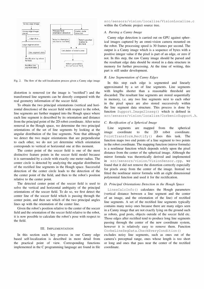
Fig. 2. The flow of the self-localization process given a Canny edge image
distortion is removed (or the image is “rectified”) and thetransformed line segments can be directly compared with thereal geometry information of the soccer field.
To obtain the two principal orientations (vertical and hori-zontal directions) of the soccer field with respect to the robot,line segments are further mapped into the Hough space whereeach line segment is described by its orientation and distancefrom the principal point of the 2D robot coordinate. After noiseremoval in the Hough space, we determine the two principalorientations of the set of line segments by looking at theangular distribution of the line segments. Note that althoughwe detect the two major orientations that are perpendicularto each other, we do not yet determine which orientationcorresponds to vertical or horizontal one at this moment.
The center point of the soccer field is one of the mostdistinctive feature points in the soccer field model becauseit is surrounded by a circle with exactly one meter radius. Thecenter circle is detected by analyzing the angular distributionof the rectified line segments in the Hough space. Successfuldetection of the center circle leads to the detection of thethe center point of the field, and then to the robot’s positionrelative to the center point.
The detected center point of the soccer field is used tosolve the vertical and horizontal ambiguity of the principalorientations of the soccer field. To do so, we first detect thecenter line of the soccer field which is passing through thecenter point, and then see which of the two principal angleslines up with the orientation of the center line.
Given the robot’s position relative to the center of the soccerfield and the orientation of the soccer field relative to the robot,it is now possible to calculate the robot’s pose with respect tothe field.
III. IMPLEMENTATION
In this section each key process in our Canny edgebased self-localization is described in more detail fromthe practical point of view. Corresponding functionsimplemented in the C programming language are found in file
src/sensors/vision/localize/VisionLocalize.cwithin the Corbenic project source tree.
A. Parsing a Canny Image
Canny edge detection is carried out on GPU against spher-ical images captured by an omni-vision camera mounted onthe robot. The processing speed is 30 frames per second. Theoutput is a Canny image which is a sequence of bytes with apositive integer value if the pixel is part of an edge, or zero ifnot. In this step, the raw Canny image should be parsed andthe resultant edge data should be stored in a data structure inmemory for further processing. At the time of writing, thispart is still under development.
B. Line Segmentation of Canny Edges
In this step each edge is segmented and linearlyapproximated by a set of line segments. Line segmentswith lengths shorter than a reasonable threshold arediscarded. The resultant line segments are stored sequentiallyin memory, i.e. any two line segments next to each otherin the pixel space are also stored successively withinthe line segment data structure. This process is done byfunction Support Image2lnseg() which is defined insrc/sensors/vision/localize/CorbenicSupport.h.
C. Rectification of a Spherical Image
Line segments are mapped from the sphericalimage coordinate to the 2D robot coordinate.PointTransform Rectify() does this task. Thefunction maps two end points of a line segment to two pointsin the robot coordinate. The mapping function (mirror formula)is a nonlinear function which depends solely upon the pixeldistance from the center of the spherical image. Although themirror formula was theoretically derived and implementedin src/sensors/vision/VisionSensor.cpp, wefound that it did not remove the distortion correctly especiallyfor pixels away from the center of the image. Instead wefitted the nonlinear mirror formula with an eight dimensionalpolynomial function and used it for the rectification.
D. Principal Orientations Detection in the Hough Space
LinesCalcInfo() calculates the Hough parameters(vertical distance between a line segment and the centerof an image, and the orientation of the line) of rectifiedline segments. A set of the rectified line segments typicallycontains many noisy ones because there are many edges seenin a Canny image that are not exactly lying on the ground suchas robots, goal posts, objects outside of the soccer field etc.Those edges after rectified tend to produce long line segmentspassing through the center of the new coordinate system,however it is relatively easy to remove them. FunctionCorbeLineSegData CheckEveryCondition()excludes noisy line segments, such as ones out of thecamera’s perceptual range, ones whose length is too shortor long and ones that pass near the center of the rectifiedcoordinate.
After the noisy line removal, functionCorbeLineSegData FindPrincipalAngle() findsthe two principal orientations (vertical and horizontalorientations) of the soccer field. It is done by a simple bincounting algorithm. We quantize the total angle into a setof bins. For each quantized bin we count the number ofline segments whose orientation fall into it or the other binperpendicular to the corresponding bin. The two principalorientations are determined by taking the bin pair which hasthe largest counting score.
E. Center Circle DetectionThe purpose of this step is to detect the unique center circle
with one meter radius. After the line segmentation of theCanny edges and rectification, we can find some line segmentswhich are linear approximating arcs of the center circle. Iftwo of such line segments are “next to” each other (spatiallyclose, originally belonged to the same edge and was storedsuccessively in the line segment data structure), it is likelythat the intersect of normal lines which passes through themiddle points of the two line segments sits close to the centerof the circle we are searching for.CorbeLineSegData FindCenterCircle() sequen-
tially looks through the line segment data. For each linesegment pair which is likely to be two approximated arcs ofthe same circle, it calculates the intersect of normal lines ofthe two segments. If the calculated intersect is approximatelyone meter away from the corresponding two line segments,the intersect is marked as a candidate of the center circle.The unique center point is chosen by a voting scheme. Foreach candidate of the center points, the function counts thenumber of candidates within its neighbor. It then chooses thecandidate which has the largest number of neighbor candidatesand calculates the mean position of the neighbor candidates,which becomes the estimated center of the center circle.
F. Calculation of Robot’s PoseCorbeLineSegData ChooseHorAngle() removes
the vertical-horizontal ambiguity of the two principalorientations in the previous step. Given the estimated centerof the soccer field, it compares the orientations of the centerline (more specifically, orientations of line segments whichcompose the center line) which passes through the centerpoint, and two of the principal directions. One of the principalorientations parallel enough to the center line becomes thehorizontal direction of the field, and the other becomes thevertical direction.CalcRobotPose() takes the robot position relative to the
center point and its orientation from the horizontal directionof the field. In the function the original robot position relativeto the center point is rotated back by the robot’s angular shiftfrom the horizontal direction in order to get the real robot’sposition relative to the soccer field.
IV. EXPERIMENTAL METHODS
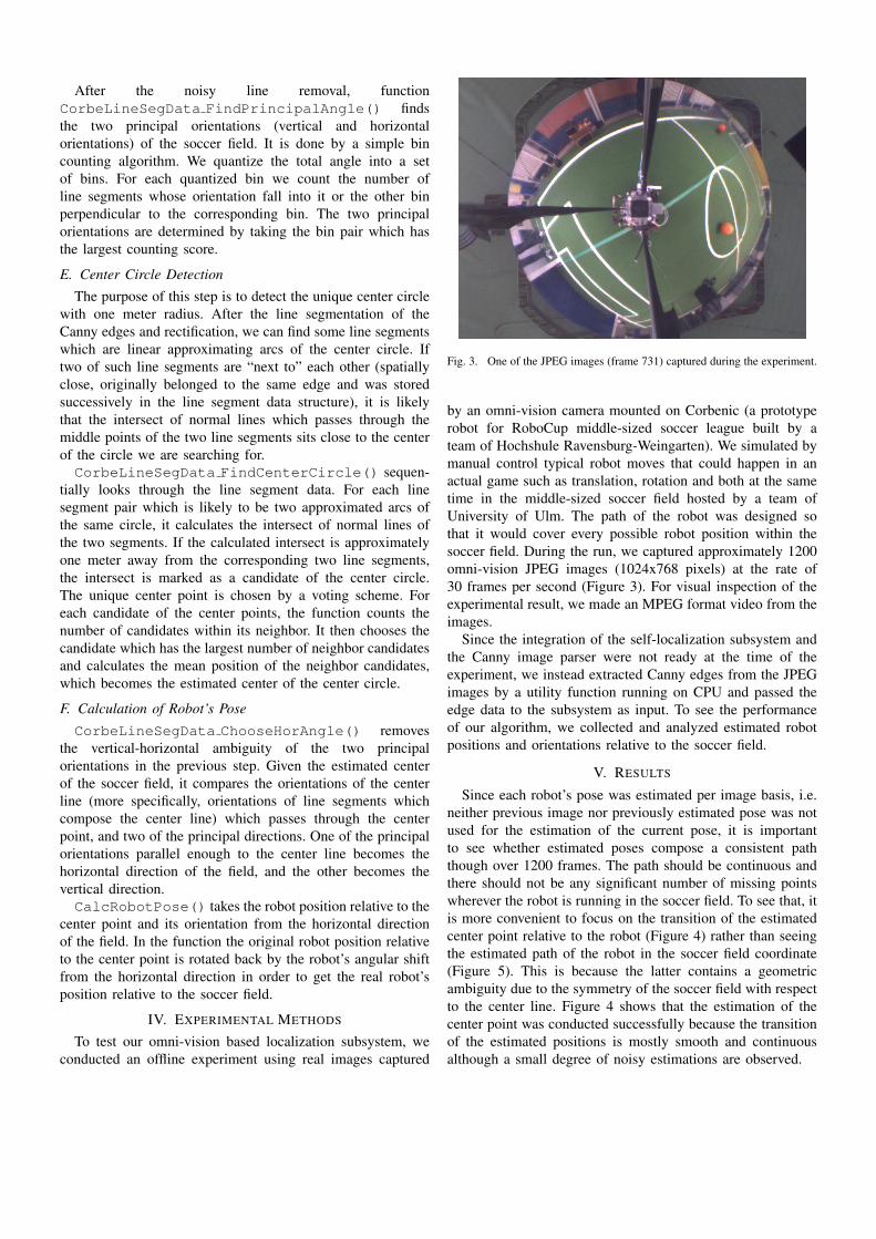
To test our omni-vision based localization subsystem, weconducted an offline experiment using real images captured
Fig. 3. One of the JPEG images (frame 731) captured during the experiment.
by an omni-vision camera mounted on Corbenic (a prototyperobot for RoboCup middle-sized soccer league built by ateam of Hochshule Ravensburg-Weingarten). We simulated bymanual control typical robot moves that could happen in anactual game such as translation, rotation and both at the sametime in the middle-sized soccer field hosted by a team ofUniversity of Ulm. The path of the robot was designed sothat it would cover every possible robot position within thesoccer field. During the run, we captured approximately 1200omni-vision JPEG images (1024x768 pixels) at the rate of30 frames per second (Figure 3). For visual inspection of theexperimental result, we made an MPEG format video from theimages.
Since the integration of the self-localization subsystem andthe Canny image parser were not ready at the time of theexperiment, we instead extracted Canny edges from the JPEGimages by a utility function running on CPU and passed theedge data to the subsystem as input. To see the performanceof our algorithm, we collected and analyzed estimated robotpositions and orientations relative to the soccer field.
V. RESULTS
Since each robot’s pose was estimated per image basis, i.e.neither previous image nor previously estimated pose was notused for the estimation of the current pose, it is importantto see whether estimated poses compose a consistent paththough over 1200 frames. The path should be continuous andthere should not be any significant number of missing pointswherever the robot is running in the soccer field. To see that, itis more convenient to focus on the transition of the estimatedcenter point relative to the robot (Figure 4) rather than seeingthe estimated path of the robot in the soccer field coordinate(Figure 5). This is because the latter contains a geometricambiguity due to the symmetry of the soccer field with respectto the center line. Figure 4 shows that the estimation of thecenter point was conducted successfully because the transitionof the estimated positions is mostly smooth and continuousalthough a small degree of noisy estimations are observed.

Fig. 4. Transition of the estimated center point of the soccer field withrespect to the robot.
Fig. 5. Transition of the estimated robot position in the soccer field.
Figure 6 shows the result of the estimation of soccerfield orientation relative to the robot. The estimated principaldirections of the soccer field are plotted. Using the MPEGvideo we visually verified that the transition of the anglesare accurate. Since we already have the differentiation ofthe vertical and horizontal orientations of the field, robot’sorientation relative the soccer field is easily derived from theresult.
Figure 5 is a plot of the estimated robot’s positions. Sincethe polarization information was not provided yet in thesubsystem, the determination of a position is up to the centerline symmetry of the soccer field. Therefore every point was
Fig. 6. Transition of the estimated principal orientations of the soccer field.
plotted on the half of the actual soccer field for visualizationof the result. However, We verified that the absolute values ofthe robot’s position parameters were estimated correctly.
VI. CONCLUSION
We have successfully designed and implemented a subsys-tem which is capable of providing self-localization informationon a RoboCup middle-sized league robot. Although the esti-mation of robot’s position contains an ambiguity with respectto the center line symmetry of the soccer field, we expectthat it will be easily resolved by combining the result withpolarization information provided by the other sensor model.
It should be noted that our localization method is basedonly upon the geometry of the soccer field. Output imagesof the omni-vision camera has color information, but suchinformation was never used for localization in this case.
Although the result of our per-frame based localizationlooks very robust in ordinary cases, there are some limitationsof the algorithm. The first is the time cost of the localizationprocess. The total RoboCup system is expected to run in realtime. Considering the speed of the Canny edge detection on theGPU is 30 frames per second, our self-localization is expectedto run at the rate of at least several frames per second. After thecompletion of the Canny image parser function, it is requiredto benchmark the time cost of the localization system, findpossible bottlenecks and optimize them if necessary.
The second major limitation of the current algorithm isthat a successful detection of the center circle is inevitablyrequired. In highly dynamic RoboCup games, occlusions ofthe center circle by robots in the playground will happenvery often. To realize robustness of self-localization in sucha scenario, an application of some estimation theory such asKalman filtering or particle filtering is strongly expected.
VII. EXTENSION OF THE WORK
In this section we list up some possible extensions regardingthe project.
• Complete the Canny parser function.• Integrate the self-localization subsystem (C code) under
Corbenic source tree (C++ code). Currently offline ex-periments using JPEG images work, however we haveto solve the name mangling problem when calling ourlocalization functions from the upper system.
• Sensor fusion with polarization data to obtain the uniqueestimate of the robot’s position in the soccer field.
• Benchmark the algorithm and optimize bottleneck pro-cesses to make it real time.
• Introduce estimation theories (e.g. Kalman Filter andParticle Filter) to realize more robust inter-frame self-localization.
ACKNOWLEDGMENT
I would like to thank Dr. Wolfgang Ertel for supervising meand giving me this enjoyable and challenging project duringmy internship program at Hochshule Ravensburg-Weingarten.He was always patient with my progress on the project andkept showing me proper research directions.
The RoboCup team at University of Ulm kindly providedus with a precious opportunity to collect the real image data intheir laboratory with a complete RoboCup middle-sized leaguesoccer field. The success of our experiment was made possiblethanks to their generosity.
My special thanks go to the folks in the RoboCup laboratoryat Hochshule Ravensburg-Weingarten. They gave me manyuseful insights and suggestions when I got lost in the project.Especially, Mr. Arne Usadel supported me in both technicaland management way.