canmet - brazil mine site rehabilitation project
TRANSCRIPT

DESIGN, CONSTRUCTION AND PERFORMANCE MONITORING OF COVER SYSTEMS FOR WASTE ROCK AND TAILINGS
VOLUME 1 – SUMMARY
MEND 2.21.4a
This work was done on behalf of MEND and sponsored by: MEND and INCO Ltd.
July 2004

DESIGN, CONSTRUCTION AND PERFORMANCE MONITORING OF COVER SYSTEMS FOR
WASTE ROCK AND TAILINGS MEND 2.21.4
VOLUME 1 SUMMARY
Prepared for MEND
Funded by MEND and INCO Ltd.
Edited by:
O'Kane Consultants Inc.
Integrated Geotechnical Engineering ServicesSpecialists in Unsaturated Zone Hydrology
OKC Report No. 702-01
July 2004

MEND 2.21.4 – Design, Construction and Performance Monitoring of Cover Systems for Waste Rock and Tailings
PREFACE
Acid rock drainage (ARD), also referred to as acid mine drainage (AMD) or acidic drainage (terms used interchangeably throughout this report), is a major mining waste management issue in Canada. A 1994 estimate (Feasby and Jones; MEND 5.8e) calculated the potential acid generating materials in Canada as 1900 million tonnes of tailings and 750 million tonnes of waste rock with a total liability between $1.9 and $5.2 billion. There are numerous examples throughout the world where elevated concentrations of metals in mine drainage have adverse effects on aquatic resources and prevent the reclamation of mine land. Metal leaching problems can occur over a wide range of pH conditions, but are particularly problematic with ARD. In North America, ARD has resulted in significant ecological damage and multi-million dollar clean-up costs for industry and governments.
The Canadian Mine Environment Neutral Drainage (MEND) initiative is a co-operative research programme that is directed by a partnership of the Canadian mining industry, federal and provincial governments and non-governmental organizations (NGOs). The original programme and its subsequent initiative MEND2000 have contributed enormously to the understanding of acidic drainage and how to prevent it. MEND3, launched in 2001, furthers this effort with a strong, research-driven programme. The mission of MEND3 is “to provide leadership and guidance on priority acidic drainage issues in Canada”. It achieves this through a multi-stakeholder coordinated programme that focuses on national and/or regional needs. An integral part of the MEND initiative continues to be its diverse and strong technology transfer activities.
INCO Ltd., in cooperation with MEND, commissioned the development of this document in 1998 as a first step in compiling a working document for the design and construction of cover systems over mine waste. The Unsaturated Soils Group at the University of Saskatchewan was asked to lead this compilation, and in cooperation with the following group of people:
• Dr. Michel Aubertin, École Polytechnique • Dr. S. Lee Barbour, University of Saskatchewan • Dr. G. Ward Wilson, University of British Columbia • Dr. Ernest Yanful, University of Western Ontario
MEND determined that an update to the manual was required in 2003 and as such funded the current version provided herein. The objective of this manual is to incorporate and integrate the best available technology on cover systems from a wide variety of sources. This document is not intended as a comprehensive design manual. It is meant to be used by mining personnel or others interested in the use of cover systems on mining waste. The control concepts behind the design and construction of cover systems are explained and illustrated. In addition, the types of activities that must be undertaken in the design process are described. The purpose of these discussions are to help mining personnel understand the background and scope of work that would be required; however, it would be expected that the detailed design would be undertaken by professionals working in this area.
Volume 1: Summary ii
MEND 2.21.4 – Design, Construction and Performance Monitoring of Cover Systems for Waste Rock and Tailings
O’Kane Consultants Inc. revised the original report under the direction of Dr. Lee Barbour, University of Saskatchewan. The revised document incorporates recent advances in cover technology. Much of this document was compiled from recent publications, such as the CANMET – CETEM Manual on Cover System Design for Reactive Mine Waste (CANMET, 2002), the Dry Covers section of the MEND Manual Volume 4 – Prevention and Control (MEND 5.4.2d), and the report prepared by the International Network for Acid Prevention on the Long-Term Performance of Dry Covers (INAP, 2003).
Dr. Michel Aubertin, École Polytechnique, Dr. G. Ward Wilson, University of British Columbia, Mr. Vincent Martin, Barrick Gold, and Dr. David Chambers, Center for Science in Public Participation, completed a peer review of the five volumes. Their assistance in improving the document is greatly appreciated.
This manual includes a summary volume (Volume 1) and the following four supporting technical documents:
• Volume 2 - Theory and Background; • Volume 3 - Site Characterization and Numerical Analyses of Cover Performance; • Volume 4 - Field Performance Monitoring, Sustainable Performance of Cover Systems; and • Volume 5 - Case Studies.
Volume 1: Summary iii

MEND 2.21.4 – Design, Construction and Performance Monitoring of Cover Systems for Waste Rock and Tailings
TABLE OF CONTENTS
PREFACE .............................................................................................................................................. II
TABLE OF CONTENTS........................................................................................................................IV
LIST OF TABLES.................................................................................................................................VII
LIST OF FIGURES..............................................................................................................................VIII
LIST OF FIGURES..............................................................................................................................VIII
1 INTRODUCTION............................................................................................................................1
1.1 SCOPE OF COVER SYSTEM DESIGN.............................................................................................5
1.2 BACKGROUND AND GENERAL DISCUSSION ON COVER SYSTEM DESIGN ........................................6 1.2.1 Cover System Objectives .................................................................................................6 1.2.2 Cover Systems for Wet-Dry Annual Climate Cycles.........................................................7 1.2.3 Cover Systems with Low Hydraulic Conductivity Layers..................................................7 1.2.4 Cover Systems with Capillary Barriers .............................................................................8 1.2.5 Reaction Inhibiting and Oxygen Consuming Cover Systems...........................................8 1.2.6 Classification of Cover Systems .......................................................................................9
1.3 FACTORS INFLUENCING COVER SYSTEM DESIGN OBJECTIVES......................................................9 1.3.1 Climate..............................................................................................................................9 1.3.2 Reactivity of the Waste ...................................................................................................10 1.3.3 Type of Waste.................................................................................................................11 1.3.4 Hydrogeologic Setting and Basal Flow...........................................................................11
2 BASIC THEORY AND FUNDAMENTAL CONCEPTS ............................................................12
2.1 UNSATURATED ZONE HYDROLOGY ............................................................................................12 2.1.1 Volume/Mass Relationships ...........................................................................................12 2.1.2 Definition of Suction........................................................................................................13 2.1.3 Soil Water Characteristic Curve......................................................................................14 2.1.4 Hydraulic Conductivity Function .....................................................................................16
2.2 COUNTER INTUITIVE NATURE OF UNSATURATED FLOW...............................................................17 2.2.1 Capillary Barriers ............................................................................................................17 2.2.2 Cover Systems on Sloping Surfaces ..............................................................................19
2.3 OXYGEN INGRESS TO REACTIVE MINE WASTE ...........................................................................19
3 SITE CHARACTERIZATION......................................................................................................21
3.1 INTRODUCTION .........................................................................................................................21
Volume 1: Summary iv

MEND 2.21.4 – Design, Construction and Performance Monitoring of Cover Systems for Waste Rock and Tailings
3.2 COMPILING AND INTERPRETING EXISTING SITE DATA .................................................................21 3.2.1 Collection of Existing Data..............................................................................................21 3.2.2 Initial Mine Site Survey ...................................................................................................22
3.3 FIELD CHARACTERIZATION AND SAMPLING PROGRAMME ............................................................23 3.3.1 Excavation of Test Pits ...................................................................................................23 3.3.2 Collection of Samples for Laboratory Characterization ..................................................23 3.3.3 In Situ Field Tests ...........................................................................................................24
3.4 LABORATORY CHARACTERIZATION PROGRAMME........................................................................26 3.4.1 Recommended Geotechnical Testing Programme.........................................................26 3.4.2 Recommended Geochemical Testing Programme.........................................................26
4 CONCEPTUAL COVER SYSTEM DESIGN .............................................................................28
4.1 INTRODUCTION .........................................................................................................................28
4.2 CONCEPTUAL DESIGN...............................................................................................................28 4.2.1 Alternate Cover System Designs....................................................................................29
4.3 APPROACH TO NUMERICAL MODELLING .....................................................................................31 4.3.1 Processes .......................................................................................................................32 4.3.2 Input ................................................................................................................................32 4.3.3 Output .............................................................................................................................33
4.3.3.1 Defining Net Percolation..........................................................................................33
4.4 NUMERICAL MODELLING METHODOLOGIES ................................................................................34 4.4.1 Purpose and Scope of Cover Design Modelling.............................................................35 4.4.2 Application of the Modelling Methodology ......................................................................36
4.4.2.1 Preliminary Modelling (1D) ......................................................................................36 4.4.2.2 Detailed Modelling (1D) ...........................................................................................37 4.4.2.3 Sensitivity Modelling (1D) ........................................................................................38 4.4.2.4 Two-Dimensional Modelling (2D) ............................................................................38
4.5 LANDFORM / LANDSCAPE ENGINEERING ....................................................................................38
5 FIELD PERFORMANCE MONITORING...................................................................................40
5.1 DATA MANAGEMENT AND INTERPRETATION................................................................................42
6 CONSTRUCTION ISSUES.........................................................................................................44
6.1 GROWTH MATERIAL LAYER THICKNESS .....................................................................................44
6.2 COVER LAYER COMPACTION ISSUES .........................................................................................44 6.2.1 Compaction Characteristics............................................................................................45 6.2.2 Special Note on Residual Soils.......................................................................................48 6.2.3 Field Compaction Trials ..................................................................................................49
Volume 1: Summary v
MEND 2.21.4 – Design, Construction and Performance Monitoring of Cover Systems for Waste Rock and Tailings
6.2.4 Compaction Equipment ..................................................................................................50 6.2.5 Quality Control During Full-Scale Construction ..............................................................51
6.3 MATERIAL PLACEMENT .............................................................................................................52
6.4 POTENTIAL COVER MATERIAL BORROW AREA(S) .......................................................................52
6.5 CONSTRUCTION SCHEDULE ......................................................................................................53
6.6 LANDFORM SHAPING ................................................................................................................53
6.7 RIPRAP MATERIAL ....................................................................................................................53
6.8 INSTALLATION OF THE PERFORMANCE MONITORING SYSTEM......................................................54
7 VEGETATION..............................................................................................................................55
7.1 SITE EVALUATION.....................................................................................................................55
7.2 VEGETATION SELECTION...........................................................................................................55 7.2.1 Factors Affecting the Selection .......................................................................................57 7.2.2 Adaptability of Species to Site ........................................................................................57 7.2.3 Vegetation Test Plots......................................................................................................58
7.3 MULCHES AND CHEMICAL STABILIZERS......................................................................................59
7.4 ESTABLISHING VEGETATION......................................................................................................59 7.4.1 Seed Bed Preparation.....................................................................................................60 7.4.2 pH Adjustment ................................................................................................................60 7.4.3 Fertilizing.........................................................................................................................60 7.4.4 Seeding Methods ............................................................................................................60 7.4.5 Vegetation Maintenance .................................................................................................61
7.5 OTHER RESOURCES .................................................................................................................61
8 SUSTAINABLE PERFORMANCE OF COVER SYSTEMS.....................................................62
9 CASE STUDIES .........................................................................................................................66
REFERENCES.....................................................................................................................................67
SUGGESTED ADDITIONAL REFERENCES ......................................................................................72
Volume 1: Summary vi

MEND 2.21.4 – Design, Construction and Performance Monitoring of Cover Systems for Waste Rock and Tailings
LIST OF TABLES
Table 1.1 Summary of cover system classifications (from MEND 2.21.3a). .......................................... 9
Table 4.1 Modelling parallels to the scientific method.......................................................................... 35
Table 5.1 Typical methods of measurement for the components of a field performance monitoring system. .......................................................................................................... 42
Volume 1: Summary vii

MEND 2.21.4 – Design, Construction and Performance Monitoring of Cover Systems for Waste Rock and Tailings
LIST OF FIGURES
Figure 1.1 Flow chart of the cover design process (adapted from O’Kane and Wels, 2003)............. 3
Figure 1.2 Scope of the conceptual system: cover performance on a 1) horizontal and 2) sloping surface, 3) internal hydraulic and geochemical performance, and 4) influence of basal flow. ...................................................................................................... 6
Figure 2.1 Schematic representation of a soil mass consisting of solids (S) with voids in between filled with water (W) and air (A) (CANMET, 2002)............................................ 12
Figure 2.2 Sub-atmospheric pressure within a capillary tube (after Fredlund and Rahardjo, 1993). .............................................................................................................................. 14
Figure 2.3 The soil water characteristic curve for different soil types (after Freeze and Cherry, 1979). .............................................................................................................................. 15
Figure 2.4 The hydraulic conductivity function (versus water content) for different soil types (after Freeze and Cherry, 1979)...................................................................................... 16
Figure 2.5 The hydraulic conductivity function (versus suction) for different soil types (after Freeze and Cherry, 1979). .............................................................................................. 17
Figure 2.6 Multi-layer cover system over waste material. ................................................................ 18
Figure 2.7 Effect of the degree of saturation on the oxygen diffusion coefficient, where De = neqD* (Mbonimpa et al., 2003). Note, the curve is based on a model, and is not a best-fit of the data points. ................................................................................................ 20
Figure 3.1 A 2.0 m test pit excavated in waste rock material. .......................................................... 24
Figure 3.2 Large-scale field screen (grizzly) used to remove material greater than 100 mm. ......... 25
Figure 4.1 Schematic illustration of the base method cover system and variations of the base method (adapted from Swanson et al., 1999). ................................................................ 29
Figure 4.2 Conceptual illustration of net percolation. ....................................................................... 34
Figure 5.1 Conceptual schematic of the components of a field performance monitoring system. ............................................................................................................................ 41
Volume 1: Summary viii

MEND 2.21.4 – Design, Construction and Performance Monitoring of Cover Systems for Waste Rock and Tailings
Volume 1: Summary xii
Figure 6.1 Conceptual relationship of compaction curves, as related to density, moulding water content, and hydraulic conductivity. Figure 6.1a illustrates the relationship between the dry unit density and moulding water content. Figure 6.1b correlates the obtained densities to the associated hydraulic conductivity (after Daniel and Wu, 1993). ....................................................................................................................... 46
Figure 6.2 Conceptual illustration of the relationship between the moulding water content, dry unit weight, and shear strength (based on shear strength and hydraulic conductivity a zone of acceptable compaction field compaction is determined) (after Daniel and Wu, 1993). ........................................................................................... 48
Figure 8.1 ..... 62 Conceptual illustration of processes affecting long-term performance (INAP, 2002)
MEND 2.21.4 – Design, Construction and Performance Monitoring of Cover Systems for Waste Rock and Tailings
1 INTRODUCTION
Waste rock or tailings containing sulphide minerals (predominately pyrite and pyrrhotite) can generate acid rock drainage (ARD). Oxidation of the sulphide minerals occurs in the presence of oxygen and water. The oxidation process is both chemical and biochemical, where biochemical oxidation occurs at a faster rate than chemical oxidation. The rate of acid generation is dependent on several factors such as temperature, pH, specific surface area of the waste particle, geometry of the waste storage facility, and availability of oxygen and water.
Over the last decade, research initiated by the mining industry in cooperation with the Mine Environment Neutral Drainage (MEND) programme, has resulted in the development of techniques that can be used to evaluate and mitigate the effects of acid mine drainage. In most cases, these techniques are based on the principle of restricting the development of conditions required for the oxidation reaction (e.g. oxygen or water) or by limiting the transport of the reaction products into the environment.
One option that has been extensively studied over the past 10 years is the use of soil covers (also referred to as “dry” covers to contrast them from water or “wet” covers) constructed over waste rock or tailings. The primary purpose of placing soil cover systems over reactive waste material is to minimize further degradation of the receiving environment following closure of the waste storage facility. Soil cover systems can be simple or complex, ranging from a single layer of earthen material to several layers of different material types, including native soils, non-reactive tailings and/or waste rock, geosynthetic materials, and oxygen consuming materials.
Current best management practice requires the placement of a cover onto most types of mine waste including tailings, waste rock and/or spent heap leach rock at closure of the mine. The objectives of a cover system may vary from site to site but generally include (i) dust and erosion control; (ii) chemical stabilization of acid-forming mine waste (through control of oxygen or water ingress); (iii) contaminant release control (through control of infiltration); and/or (iv) provision of a growth medium for establishment of sustainable vegetation.
Dust and erosion are minimized by the placement of a layer of material suitable for the growth of vegetation to stabilize the soil. Mulch can also be used to temporarily stabilize the surface, especially before vegetation has become established. Erosion can also be controlled by shaping the landform of the cover surface; for example, hummocks are often used in wet climates to minimize erosion during rainfall events.
The principal mechanism utilized to inhibit oxygen ingress is the development of saturated conditions within the cover. This “blanket” of water (i.e. a tension saturated layer of cover material) limits the oxygen diffusion rate into the waste to the rate at which oxygen can diffuse through water; in essence, providing a “water” cover without the requirement for a surface pond.
Volume 1: Summary 1

MEND 2.21.4 – Design, Construction and Performance Monitoring of Cover Systems for Waste Rock and Tailings
Limiting the net infiltration of water into the waste is generally achieved by one of two methods. The cover may be constructed of materials with a sufficiently low hydraulic conductivity barrier so as to limit downward percolation of rainfall or snowmelt. This water is then stored near the surface of the soil cover or is released as surface runoff. Alternatively, infiltrating water is stored within the cover near the ground surface where it can be subsequently released via evapotranspiration. In these “moisture store-and-release” type covers, the objective is to minimize deep percolation of water by returning all infiltration waters to the atmosphere. Obviously, the local climate plays a major role in whether a “barrier” or “moisture store-and-release” type soil cover is required.
The establishment of sustainable vegetation is achieved by placing a layer of soil appropriate for the growth of the target vegetation type. The important factors when designing a vegetative soil layer are the physical and chemical characteristics of the soil, and the soil must have sufficient nutrients to support healthy vegetation. The layer must also have sufficient water storage capacity throughout the growing season, and the hydrology of the site must be such that there is no potential for contaminants to migrate into the vegetative layer.
In general, there is a tendency by stakeholders to develop performance criteria for a cover system, which are tied directly to these specific design objectives. In many cases, this practice has led to the development of single, often very conservative, numerical values of cover performance criteria such as “net percolation”, “rate of oxygen ingress” and/or “plant density/mixture”. Figure 1.1 puts forward a methodology for developing site-specific performance criteria for a cover system designed to control ARD. The methodology described by the flow chart links the predicted performance of a cover system to groundwater and surface water impacts. This way, the appropriate level of control (of oxygen ingress and/or net percolation) required by the cover system can be determined, and cover system performance criteria can be developed on a case-by-case basis, with due consideration of the short-term and long-term impacts on the receiving environment at a particular site.
The flowchart in Figure 1.1 outlines five fundamental stages of designing a cover system, as described by O’Kane and Wels (2003). The first stage involves a site and material characterization, which defines the type of waste, the size and geometry of the waste storage facility, the site-specific climate conditions, as well as other pertinent factors. The second stage, the preliminary design stage, starts with a conceptual cover design, where the appropriate type of cover system is chosen based on the available material, the local climate, and the conceptual objectives for the cover system. This stage also involves the analysis of the basic cover system design. This analysis often consists of numerical modelling to explore different cover system design options and allows the design parameters (e.g. cover thickness) to be related to performance (e.g. net percolation). The third stage is an assessment of potential impacts on the receiving environment. The purpose of the impact assessment is to relate the cover system design parameters (e.g. cover thickness) to environmental impacts (e.g. groundwater quality). This stage also typically involves numerical modelling, such as seepage and contaminant transport modelling. The impacts quantified in this stage (such as contaminant loadings into groundwater) are compared to regulatory standards, or a risk assessment is completed with respect to the impact on the receiving environment. If the impacts do not comply,
Volume 1: Summary 2

MEND 2.21.4 – Design, Construction and Performance Monitoring of Cover Systems for Waste Rock and Tailings
or are not acceptable based on the risk assessment, then changes to the preliminary cover system design must be undertaken. If changes to the basic cover system design are not sufficient for compliance, then a “fatal flaw” is triggered, which involves a new conceptual design. If the predicted impacts comply, then the preliminary cover system design is acceptable and the cover system design process can proceed to the fourth stage, the final design stage. The final design stage involves field trials and performance monitoring and the detailed design. The field trials and performance monitoring verify the impacts determined from the impact analysis, as well as the predicted performance of the cover system design. In general, a few alternate cover system designs are identified during the aforementioned stages, which typically result in the implementation of more than one field trial. The detailed design then uses the information developed from the field trials to finalize the optimum cover system design for preparation of construction documents and information. This leads to the final stage: cover construction and long-term performance monitoring.
Long-Term Performance Monitoring
Unacceptable Risk
Cover Construction
Conceptual Design Preliminary Design
Numerical Modelling
Impact Analysis
Field Trials & Performance Monitoring
Detailed Design
Fatal Flaw Fatal Flaw
Noncompliance
Site and Material Characterization
Figure 1.1 Flow chart of the cover design process (adapted from O’Kane and Wels, 2003).
Volume 1: Summary 3

MEND 2.21.4 – Design, Construction and Performance Monitoring of Cover Systems for Waste Rock and Tailings
This manual has been organized into a handbook format. The main document (the “handbook”) is a summary of the key points critical to the design of soil cover systems. The handbook is divided into sections based on the flowchart shown in Figure 1.1. Each section provides an overview of the relevant information and then refers the reader to a subsequent volume where the subject is discussed in detail. This allows the reader to pursue the subjects that are critical to his or her own design process, without becoming mired in a lengthy tome of information. An additional benefit to this organization method is that the volumes can be updated as new information becomes available. This is particularly applicable to the volume on case studies.
The only aspect of the flowchart outside the scope of this manual is the impact analysis and compliance/risk assessment. Hence, further discussion is not provided on this aspect except to reiterate that the impact analysis quantifies the relationship between cover performance criteria and environmental impacts. The specific environmental impacts to be evaluated depend on the objective(s) of the proposed cover system design and local regulations. The environmental impacts most commonly evaluated during cover system design include:
• Impacts on surface water quality;
• Impacts on groundwater quality;
• Impacts on air quality;
• Impacts on vegetation; and
• Impacts on wildlife.
Section 2 presents the basic theory of unsaturated zone hydrology and introduces several key concepts with respect to the design of cover systems. Section 3 discusses site characterization, including laboratory and field methods for evaluating potential cover materials. Section 4 presents the elements of conceptual cover system design and the approach to numerical modelling. Section 5 outlines field performance monitoring of test-scale and full-scale cover systems. Construction issues relating to cover placement are discussed in Section 6. Vegetation is discussed in Section 7. Section 8 addresses the issues of erosion, surface water management, and landform evolution as well as a discussion on sustainable performance of cover systems. Finally, case studies are discussed in Section 9. The case studies (Volume 5) are provided to illustrate the application of the technology described in previous sections of the manual. In addition, the case studies will be used to discuss the importance of addressing practical and technical considerations such as clay mineralogy, development of borrow material areas, and cover system construction.
The case studies will also highlight key areas, or issues, of technology development, which have resulted from the research. The objective will be to determine whether the case study has provided a “lesson learned” with respect to the methodology utilized to design the cover system associated with the case study, rather than attempt to identify a specific design that can be transferred from site to site. Transferring a cover system design from one site to another for the simple reason that it
Volume 1: Summary 4

MEND 2.21.4 – Design, Construction and Performance Monitoring of Cover Systems for Waste Rock and Tailings
“worked” at the first site is one of the most common “fatal flaws” with respect to cover systems. Hence, the case studies will focus on whether the field data has identified a flaw in the cover system design methodology and/or philosophy such that a fundamental question can be addressed: Would the methodology utilized to design the cover system for the particular case study have been different if the information gained from the field performance monitoring been available at the start of the project? This approach to evaluating and presenting the case studies within this manual will highlight the importance of applying a proven and constantly updated methodology to cover system design. The fundamental message is that it is the cover system design methodology that is transferable from one site to the next, as opposed to the transfer of a particular cover system design from site to site.
1.1 Scope of Cover System Design
Figure 1.2 illustrates the scope of the conceptual system involving a cover system on a waste rock storage facility. The scope includes the:
• Performance of the cover on a relatively horizontal surface;
• Performance of the cover on a sloping surface;
• Internal hydraulic and geochemical performance of the waste material (including internal gas, heat, and moisture dynamics); and
• Influence of basal flow as a result of placing the waste material on a valley wall, a groundwater discharge area, and/or historic surface water path.
Integration at the conceptual, basic, and detailed cover system design stages of each component of the scope as listed above is the key to implementing the optimum cover system with respect to technical and economic feasibility. It will also ensure the best opportunity for long-term sustainable cover system performance as well as for developing a credible closure strategy.
In general, the first item is well understood and addressed during the design of cover systems. However, the second and fourth items will significantly influence the metal loading released from the waste material. For example, some documented case studies of “cover system failures” are in fact a result of the cover system being designed for a horizontal surface while being constructed on a sloping surface. The performance of a cover system on a sloping surface can be much different as compared to a horizontal surface and the difference in performance relates to site climate conditions, the slope length and angle, and the material properties. Numerous other documented “cover system failures” can be attributed to the influence of basal flow resulting from placing the waste on valley walls, basins, groundwater discharge features, and historic surface water paths. In these cases, the release of acidic drainage from the waste storage facility following cover placement was due not only to incident precipitation on the surface, but also sub-surface basal flow leaching oxidation products from the storage facility. In many cases, the latter contribution to the release of contaminants of concern from the waste storage facility can be a significant, if not dominating, component.
Volume 1: Summary 5

MEND 2.21.4 – Design, Construction and Performance Monitoring of Cover Systems for Waste Rock and Tailings
Figure 1.2 Scope of the conceptual system: cover performance on a 1) horizontal and 2) sloping surface, 3) internal hydraulic and geochemical performance, and 4) influence of basal flow.
1.2 Background and General Discussion on Cover System Design
1.2.1 Cover System Objectives
The two principal design objectives of cover systems are:
1) To function as an oxygen ingress barrier for the underlying waste material by maintaining a high degree of saturation within a layer of the cover system, thereby minimizing the effective oxygen diffusion coefficient and ultimately controlling the flow of oxygen across the cover system; and
2) To function as a water infiltration barrier for the underlying waste material as a result of the presence of a low permeability layer and/or a moisture store-and-release layer.
Additional design objectives for cover systems placed on reactive tailings and/or waste rock can include:
1) Prevention of mechanical weathering of the underlying waste material;
2) Control of consolidation and differential settlement;
3) Oxygen consumption (i.e. organic cover materials);
4) Reaction inhibition (i.e. incorporate limestone at the surface to control the rate of oxidation (does not prevent oxidation)); and
5) Control of upward capillary movement of process water constituents/oxidation products.
Volume 1: Summary 6

MEND 2.21.4 – Design, Construction and Performance Monitoring of Cover Systems for Waste Rock and Tailings
1.2.2 Cover Systems for Wet-Dry Annual Climate Cycles
It is difficult and usually not economically feasible in arid and semi-arid climates to construct a cover system that contains a layer that remains highly saturated to reduce oxygen transport. The cover system will be subjected to extended dry periods and therefore the effect of evapotranspiration will be significant. However, subjecting the cover system to evaporative demands can be beneficial in arid and semi-arid climates and result in a reduction of infiltration to the underlying sulphidic waste material. A homogeneous upper cover surface layer with a well-graded texture and possessing sufficient storage capacity can be used to retain water during rainfall events. The storage layer releases a significant portion of pore-water back to the atmosphere by evapotranspiration during extended dry periods, thereby significantly controlling the net percolation across the cover system and into the underlying waste material. The objective is to control acidic drainage as a result of preventing moisture movement into and through the waste material. A cover system with the above objectives is often referred to as a “moisture store-and-release” cover system.
An issue that arises with respect to a cover system designed to only limit net moisture percolation to the underlying waste is the question of only decreasing seepage, leading to higher concentrations and ultimately the same loading to the environment. In general, there is not complete agreement as to whether very low net percolation rates will lead to the same loading or a reduced loading. It is argued that the low percolation rates associated with a properly designed moisture store-and-release cover system (with no oxygen control) will eventually lead to contaminant release. Conversely, it can be argued that there must be a reduction in loading for a percolation rate given that: “zero flow corresponds to zero loading release”. In addition, at lower percolation rates the leachable areas of waste rock, for example, will be greatly reduced (albeit the finer textured material will contain higher concentrations of leachable contaminants). Finally, even a moisture store-and-release cover system will provide protection from mechanical weathering and breakdown of waste rock (i.e. freeze-thaw and wet-dry cycles), thus ensuring that the source of contaminant loading does not rapidly increase following decommissioning.
1.2.3 Cover Systems with Low Hydraulic Conductivity Layers
A low hydraulic conductivity layer, which is typically achieved through compaction of local borrow material, will restrict percolation to the underlying waste. A growth medium, or non-compacted layer, must overlay the compacted layer. It is fundamental to note however that while net percolation will be restricted by the presence of the low hydraulic conductivity layer, the growth medium’s ability to store and release moisture will remain as a significant factor influencing net percolation to the underlying waste. In general, one of the primary benefits of the compacted layer will be in “holding up” water for a sufficient time to allow for the moisture to evapotranspirate. This aspect of cover system performance is indicative of climate conditions where pronounced wet and dry seasons are prevalent, unless the hydraulic conductivity of the compacted layer is in the range of that typical for a compacted smectitic clay layer. In addition, the presence of a low hydraulic conductivity layer on a sloping
Volume 1: Summary 7

MEND 2.21.4 – Design, Construction and Performance Monitoring of Cover Systems for Waste Rock and Tailings
surface will also promote lateral diversion of moisture flow, also reducing net percolation to the underlying waste.
Significant potential exists for increasing the hydraulic conductivity of the compacted layer as a result of altering the structure of this layer during wet-dry cycles or freeze-thaw cycles. Hence, while it is commonly accepted that the characteristics of a low hydraulic conductivity layer are the most important component of a cover system, the thickness and characteristics of the overlying growth medium are just as critical, if not more so, in terms of long-term performance of the compacted layer and the entire cover system.
The low hydraulic conductivity layer discussed above is also a layer that typically possesses the ability to retain moisture, thus creating a “blanket” of water (i.e. a tension saturated layer of cover material) over the reactive waste material, which inhibits oxygen ingress.
1.2.4 Cover Systems with Capillary Barriers
The capillary barrier concept is commonly used in the design of mine waste cover systems and more specifically, the design of multi-layer cover systems. The capillary barrier concept can be used to maintain a tension saturated layer within the cover system and thus mitigate oxygen ingress. A fine-textured material placed between an underlying and overlying coarse-textured material can result in a capillary barrier for downward as well as upward moisture migration from the “sandwiched” layer. The result is a layer within the cover system that maintains tensions saturated conditions, thus controlling oxygen diffusion to the reactive waste.
A capillary barrier will result when a fine-textured soil overlays a coarse-textured soil, although a capillary break can also develop when the coarse-textured materials overlies a fine-textured material. The design of a capillary barrier is dependent on the contrast between the hydraulic properties of both the coarse and fine materials. Capillary barriers, unlike compacted barriers, do not rely solely on a low hydraulic conductivity layer to restrict moisture movement into the underlying material. Processes that increase hydraulic conductivity, such as desiccation and freeze-thaw, do not necessarily decrease the effectiveness of a capillary barrier.
Additional discussion on capillary barriers and preferential flow in coarse and fine-textured materials is provided in Section 2.
1.2.5 Reaction Inhibiting and Oxygen Consuming Cover Systems
The function of cover systems with a reaction-inhibiting barrier is to provide an environment that results in a significant reduction of the intrinsic sulphide oxidation rates (MEND 2.20.1). Materials such as flyash and limestone can be incorporated into the cover system to provide alkalinity. This results in an increase in the pH of the waste material pore-water, which in turn reduces the rate of sulphide oxidation and neutralizes any existing acid.
Volume 1: Summary 8

MEND 2.21.4 – Design, Construction and Performance Monitoring of Cover Systems for Waste Rock and Tailings
The purpose of oxygen consuming cover systems is to provide an environment that acts as an oxygen sink, thereby reducing the oxygen available to the waste material. Organic materials, such as wood chips or municipal waste compost, or non-acid generating materials containing sulphides, such as desulphurized tailings, are examples of materials that can be used in oxygen consuming cover layers.
1.2.6 Classification of Cover Systems
The design objectives for cover systems form the basis for classification of cover systems, which are shown in Table 1.1. MEND 2.21.3a classified cover systems that control acid generation as: oxygen transport barriers; oxygen consuming barriers; reaction inhibiting barriers; and moisture store-and-release infiltration barriers. An infiltration barrier was added to include covers designed based on a low conductivity layer.
Table 1.1 Summary of cover system classifications (adapted from MEND 2.21.3a).
Cover system Classification Primary Role of Cover System in Inhibition of ARD
Oxygen transport barriers Act to retain moisture and hence provides a low diffusion
barrier to atmospheric oxygen
Oxygen consuming barriers Act as an oxygen consuming sink to provide low oxygen
concentrations at the interface
Reaction inhibiting barriers Act to inhibit reactions, neutralizes pH
Moisture store-and-release infiltration barriers
Act to minimize moisture flux by maximizing near surface storage of moisture with subsequent release by
evapotranspiration
Infiltration barrier Act to minimize moisture flux by providing a low
conductivity layer.
1.3 Factors Influencing Cover System Design Objectives
Several factors influence and often dictate the design objectives of a cover system. The key factors are likely: climate conditions; waste material reactivity; type of waste material (i.e. tailings or waste rock); hydrogeologic setting; and basal inflow conditions. These factors are discussed below.
1.3.1 Climate
The climate conditions at the mine site are a key factor in determining the cover system objectives. Is it generally a “dry” site (potential evaporation greatly exceeds annual precipitation), or is it generally a “wet” site (annual precipitation meets or exceeds annual potential evaporation)? However, caution is required when using these “annual” criteria for characterizing wet climates at a site. Numerous sites
Volume 1: Summary 9

MEND 2.21.4 – Design, Construction and Performance Monitoring of Cover Systems for Waste Rock and Tailings
exist where precipitation exceeds potential evaporation on an annual basis; however, the site typically experiences hot, dry months where evaporation greatly exceeds rainfall. These dry summer conditions can make it difficult to design a cover system that meets all objectives throughout the year. Where the potential evaporation exceeds precipitation on an annual basis, a similar level of caution is required. In many instances, the site will experience high intensity and short duration rainfall conditions, which may exceed the storage capacity of the cover material. Particular caution is required when there is potential for consecutive significant rainfall events, which limit the time frame for evapotranspiration to remove moisture from the previous event and therefore increase the net percolation.
1.3.2 Reactivity of the Waste
The reactivity of the waste material is an important factor in determining the cover system objectives. The reactivity of the waste is often determined from a contaminant source assessment. A contaminant source assessment focuses on determining the potential for the waste material to produce pore-water that may cause an adverse impact or be non-compliant with respect to a regulatory requirement. Typical contaminants include, but are not limited to, pH, acidity, alkalinity, sulphates, nutrients, metals, and radionuclides. In terms of reactive mine waste, the contaminant source assessment of existing impacts is to determine whether groundwater and/or surface water has been impacted by the presence of the waste storage facility, or the mine operations in general. For example, in the case of inert or non-reactive tailings, the only contaminants in tailings seepage are those originally introduced to the impoundment with the process water. These contaminants can include elevated concentrations of copper or cyanide for example, and all major ions, resulting in a high ionic strength tailings pore-water. This manual generally addresses reactive waste; however, non-reactive waste can also require specific design requirements based on the tailings pore-water.
Reactive waste will usually indicate that a “higher” quality cover system is required to control further reactions. For example, if tailings are reactive, they may oxidize and release contaminants (i.e. oxidation products such as sulphate and metals) into the tailings pore-water. The degree of contamination resulting from tailings oxidation (both with respect to make-up of contaminants and contaminant concentrations) depends on the buffering capacity of the system (i.e. buffering capacity of the tailings as well as resident process water). The tailings pore-water will become acidic quickly if there is limited or no buffering capacity, resulting in accelerated oxidation and a large increase in sulphate and dissolved metals. In contrast, if there is significant alkalinity (buffering potential) in the tailings, the acidity released during sulphide oxidation will be neutralized, maintaining a circum-neutral pH. The rate of oxidation is limited at this pH and many metals of concern are immobile; however, some contaminants may stay in solution at elevated concentrations albeit at concentrations much lower than in the case of no buffering. Clearly then, the level of reactivity and buffering capacity of the waste will determine the design objectives of the cover system. In addition, the solubility of some metals is higher at circum-neutral pH, compared to acidic conditions. Finally, metals such as Zn and As, which may have been introduced to the pore-water as a result of sulphide oxidation and low pH
Volume 1: Summary 10

MEND 2.21.4 – Design, Construction and Performance Monitoring of Cover Systems for Waste Rock and Tailings
pore-water conditions, remain in solution at neutral pH conditions (i.e. after some buffering has occurred), resulting in elevated metal concentrations even for neutral drainage conditions.
1.3.3 Type of Waste
Assuming the waste material is sulphidic and reactive (with or without buffering capacity), the cover objectives will also be a function of whether the material is tailings or waste rock. The texture of the waste material has an impact on determining the cover system objectives; a tailings material will typically be poorly drained, higher in moisture content, and finer-textured, while waste rock is typically drained, coarser-textured and with comparatively low moisture contents.
These differing textural conditions between tailings and waste rock may also determine the cover system objectives from a construction perspective. It can be very difficult to place a cover over saturated fine tailings, while the integrity of the waste rock surface is typically not an issue. The differing texture between waste rock and tailings also influences cover system objectives due to the differing dominant mechanisms of oxygen transport. Finally, waste rock piles are typically associated with steeper and longer side slopes as compared to tailings impoundments, which are generally contained by dams.
1.3.4 Hydrogeologic Setting and Basal Flow
The hydrogeologic setting of a waste disposal facility will significantly control the cover system objectives. For example, many sites are characterized by a tailings basin located within a groundwater system with significant lateral groundwater transport (i.e. the tailings water table is controlled by the groundwater system and not incident precipitation falling on the tailings surface). In these cases, leaching of process water and remnant acidity will take place regardless of the ability of the cover system to control net percolation.
Waste rock is often end-dumped from valley walls and slopes. These walls and slopes will invariably have historic surface water paths. The waste rock placed over the paths will be subjected to seasonal flushing resulting from the water table rising past the waste rock-valley wall interface into the waste rock. Alternatively, waste rock placed on fractured bedrock and faults where groundwater flow is focused can also be subject to seasonal flushing of stored acidity and metals. This long-term seasonal flushing of the waste rock will influence the cover objectives.
Volume 1: Summary 11

MEND 2.21.4 – Design, Construction and Performance Monitoring of Cover Systems for Waste Rock and Tailings
2 BASIC THEORY AND FUNDAMENTAL CONCEPTS
This section provides a basic introduction to the theoretical principles that govern soil cover design. The majority of this theoretical background relates to the hydrology of the unsaturated zone. A more detailed presentation of the theoretical basis for soil cover design is provided in Volume 2.
2.1 Unsaturated Zone Hydrology
The principle phenomenon of interest in soil cover design is the transient flow of water within unsaturated soil. Two fundamental processes describe any transient phenomenon: flow and storage. In the case of the soil cover, the primary issues of concern are the mechanisms responsible for the storage and movement of water in unsaturated soil.
Increasing Moisture Content
S = 100%
S
1 > S >S(S < 100%)
rS = S (S <<<<< 100%)
r
S
AA
A
S
W
Figure 2.1 Schematic representation of a soil mass consisting of solids (S) with voids in between filled with water (W) and air (A) (CANMET, 2002).
2.1.1 Volume/Mass Relationships
An unsaturated soil is comprised of three principal phases: solid soil particles, water, and air. A set of simple terminology is required to define the mass and volume relationships for these phases. A central concept in the performance of soil covers is the ability to relate the change in the volume of water stored in the cover to a net flux into the cover. Consider the simple cover shown in Figure 2.1. The initial volumetric water content within the cover is approximately 10% and the cover is one metre thick. The definition of volumetric water content is the volume of water divided by the volume total; therefore, the thickness of the cover (1 m) can be multiplied by the initial volumetric water content (10%) to calculate that the volume of water stored in the cover, which is 0.1 m3 for every square metre of cover surface area. If an additional 150 mm of water were added to this cover, then the
Volume 1: Summary 12
MEND 2.21.4 – Design, Construction and Performance Monitoring of Cover Systems for Waste Rock and Tailings
water content would have to increase from 10% to 25%. The maximum amount of water that could be stored in this soil at saturation can be calculated from the saturated volumetric water content, equal to the porosity. If the porosity of this soil cover was 30%, then the maximum volume of water (at saturation) within the cover would be 300 mm.
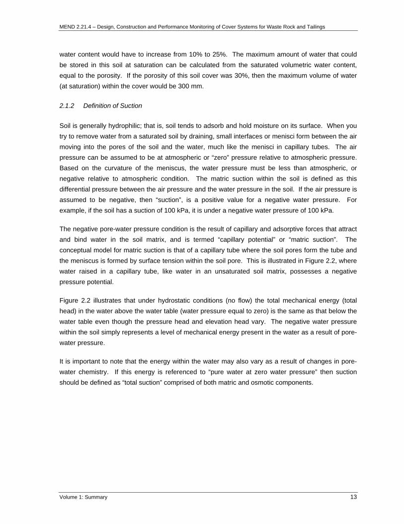
2.1.2 Definition of Suction
Soil is generally hydrophilic; that is, soil tends to adsorb and hold moisture on its surface. When you try to remove water from a saturated soil by draining, small interfaces or menisci form between the air moving into the pores of the soil and the water, much like the menisci in capillary tubes. The air pressure can be assumed to be at atmospheric or “zero” pressure relative to atmospheric pressure. Based on the curvature of the meniscus, the water pressure must be less than atmospheric, or negative relative to atmospheric condition. The matric suction within the soil is defined as this differential pressure between the air pressure and the water pressure in the soil. If the air pressure is assumed to be negative, then “suction”, is a positive value for a negative water pressure. For example, if the soil has a suction of 100 kPa, it is under a negative water pressure of 100 kPa.
The negative pore-water pressure condition is the result of capillary and adsorptive forces that attract and bind water in the soil matrix, and is termed “capillary potential” or “matric suction”. The conceptual model for matric suction is that of a capillary tube where the soil pores form the tube and the meniscus is formed by surface tension within the soil pore. This is illustrated in Figure 2.2, where water raised in a capillary tube, like water in an unsaturated soil matrix, possesses a negative pressure potential.
Figure 2.2 illustrates that under hydrostatic conditions (no flow) the total mechanical energy (total head) in the water above the water table (water pressure equal to zero) is the same as that below the water table even though the pressure head and elevation head vary. The negative water pressure within the soil simply represents a level of mechanical energy present in the water as a result of pore-water pressure.
It is important to note that the energy within the water may also vary as a result of changes in pore-water chemistry. If this energy is referenced to “pure water at zero water pressure” then suction should be defined as “total suction” comprised of both matric and osmotic components.
Volume 1: Summary 13

MEND 2.21.4 – Design, Construction and Performance Monitoring of Cover Systems for Waste Rock and Tailings
hydrostatic
ψtotal
Increasing Particle Size
ψpressure ψelevation
Negative PoP
Pore WaterP e
re Water ressure
Positive
ressur
Decreasing Moisture Retention
Figure 2.2 Sub-atmospheric pressure within a capillary tube (after Fredlund and Rahardjo,
1993).
2.1.3 Soil Water Characteristic Curve
The simple example provided in Figure 2.2 illustrates that pores of different sizes will tend to drain at varying levels of suction. In a soil, the pores are not a single size but vary over a large range depending on the particle size and structure of the soil. A relationship exists between the volumetric water content and the suction within the soil and is referred to as the soil water characteristic curve (SWCC) or moisture retention curve.
Measurement of the SWCC is central to the design of any unsaturated system, such as a cover system, because it describes the fundamental relationship between the energy state of the pore-water and the volume of water stored within the soil pores. Figure 2.3 presents representative SWCCs for fine and coarse-textured materials. The negative pore-water pressure required to initiate drainage of an initially saturated soil is called the air entry value (AEV). The SWCC is obtained from a laboratory test in which the volumetric water content of a soil sample is measured at different applied suctions.
A finer textured material has the ability to retain moisture under higher suction values as compared to the coarse material because of smaller pore sizes. Hence, the coarser textured material starts to “drain” first as suction is increased from saturated conditions, and de-saturates as suction continues to increase. In contrast, the finer textured material remains at the saturated volumetric water content (i.e. porosity) for the same suction condition. This phenomenon is referred to as “tension saturated” conditions. Ultimately the finer textured material will also begin to drain as the suction is increased.
Volume 1: Summary 14

MEND 2.21.4 – Design, Construction and Performance Monitoring of Cover Systems for Waste Rock and Tailings
The rate at which the water content decreases with increasing suction is a function primarily of the particle size distribution of the material, but also other factors such as density and void ratio, which are discussed in more detail in Volume 2. A uniform material will tend to drain “rapidly” over a small range of suction values because the pore sizes are generally the same size. Well-graded materials will have a moderate slope to the SWCC once drainage conditions are initiated because they possess a wide range of pore sizes. A well-graded material will drain under higher and higher suction values starting with the larger pore sizes first as the negative pore-water pressures overcome the water tension conditions within the pores.
Negative Pore-Water Pressure (Suction)
Positive Pore-Water Pressure
Volumetric Water Contentor
Degree of Saturation
Clay Silt Sand Gravel
Air Entry Value
Residual Water Content
Log scale
Figure 2.3 The soil water characteristic curve for different soil types (after Freeze and Cherry, 1979).
Soil structure, aggregation, initial moulding water content of a compacted soil, method of compaction, void ratio, type of soil, soil texture, mineralogy, stress history, and weathering effects are all factors that influence the behaviour of the SWCC (Vanapalli, 1994). These factors also influence the hydraulic and mechanical properties of an unsaturated soil. However, stress history and initial moulding water content probably have the most influence on soil structure and aggregation, especially for fine-textured soils. Specimens of a particular soil, with the same texture and mineralogy, can exhibit different soil water characteristic curves if they are prepared at different initial moulding water contents and possess different stress histories. The engineering behaviour of each of the specimens will differ as a result. The key factors affecting the shape of a SWCC are discussed further in Volume 2.
Volume 1: Summary 15

MEND 2.21.4 – Design, Construction and Performance Monitoring of Cover Systems for Waste Rock and Tailings
2.1.4 Hydraulic Conductivity Function
Hydraulic conductivity refers to the ability of a soil to transmit moisture. Water will move through soil in response to energy gradients. These gradients are commonly due to mechanical energy gradients (e.g. total head comprised of pressure head and elevation head) but may also be due to thermal, electrical, or chemical energy gradients (Mitchell, 1976). The relationship between the unit flux of water in response to a mechanical energy gradient is commonly referred to as Darcy’s Law and is written as follows:
kiq −= [2.1]
where q = unit flux of water (m/s), k = hydraulic conductivity (m/s) and i = energy gradient (unitless).
Darcy’s Law is applicable to soil, regardless of whether it is saturated or unsaturated. The key difference, however, is that the hydraulic conductivity of a saturated soil is often taken as a constant whereas the hydraulic conductivity of an unsaturated soil will change with the degree of saturation or volumetric water content (See Figure 2.4). Volumetric water content can be related to suction through the SWCC, and hence this function can also be described by a relationship between hydraulic conductivity and suction as shown in Figure 2.5. Detailed descriptions of the theory of water flow in unsaturated soils are well defined by Freeze and Cherry (1979), Fredlund and Rahardjo (1993), and Guymon (1994).
Hydraulic Conductivity
Volumetric Water
Content
Clay
Silt Sand
Gravel
Saturated Dry
Log scale
Figure 2.4 The hydraulic conductivity function (versus water content) for different soil types (after Freeze and Cherry, 1979).
Volume 1: Summary 16

MEND 2.21.4 – Design, Construction and Performance Monitoring of Cover Systems for Waste Rock and Tailings
Hydraulic Conductivity
Suction Log scale
Clay
Silt Sand
Gravel Log scale
Figure 2.5 The hydraulic conductivity function (versus suction) for different soil types (after Freeze and Cherry, 1979).
2.2 Counter Intuitive Nature of Unsaturated Flow
The key theoretical concepts related to the design of cover systems are the soil-water characteristic curve (SWCC), the hydraulic conductivity function, the capillary barrier concept, and the relationship between degree of saturation and the diffusion of oxygen. MEND 2.21.3a, MEND 5.4.2d, and others describe these concepts in detail.
Unsaturated flow is counter-intuitive to saturated flow, which is typically encountered in groundwater. A detailed discussion of unsaturated flow and storage is presented in Volume 2, including issues of evaporation, preferential flow, basal inflow, wetting, and pore-water velocity. These issues are important to understand to ensure accurate and defensible analysis, design, and review of cover systems for reactive mine waste. The following discussion is limited to an introduction of capillary barriers and oxygen ingress to reactive mine waste.
2.2.1 Capillary Barriers
The capillary barrier concept is commonly used in the design of cover systems and more specifically, the design of multi-layer cover systems. Rasmusson and Erikson (1986), Nicholson et al. (1989), Morel-Seytoux (1992), Aubertin et al. (1996), Bussière and Aubertin (1999), MEND 2.22.2a, and others, describe the capillary barrier concept in detail. The concept is introduced here, with a more detailed discussion in Volume 2 as well as Volume 3.
A capillary barrier results when a finer textured material overlays a coarser textured material, as illustrated in Figure 2.6. The design of a capillary barrier is dependent on the contrast between the hydraulic properties of both the coarse- and fine-textured materials.
Volume 1: Summary 17

MEND 2.21.4 – Design, Construction and Performance Monitoring of Cover Systems for Waste Rock and Tailings
Coarse Textured Soil Layer
Coarse Textured Soil Layer
Fine Textured Soil Layer
Waste Material
Figure 2.6 Multi-layer cover system over waste material.
The lower coarse-textured material may drain to a residual moisture content if conditions allow. The residual suction for coarse-textured material is relatively low compared to the finer textured material but the hydraulic conductivity of the sand is considerably lower at residual than at saturation. The overlying fine-textured material will not drain at this low suction and as a result, it remains in a tension saturated condition. This “capillary” break will occur whenever the residual suction of the lower coarse-textured material is less than the AEV of the upper fine-textured material. A second coarse-textured layer overlying a fine-textured layer may also be included in the design of a capillary barrier system. The role of this coarser layer is to prevent evaporation from the fine-textured layer. The upper coarse-textured layer may also reduce runoff because it provides for storage of water following infiltration. Infiltration into the coarse layer also allows some water to reach the underlying fine-textured material and satisfy any antecedent moisture losses.
In summary, the capillary barrier concept is utilized in the design of cover systems for two primary reasons. The first is to keep a central, fine-textured layer near saturation under all climatic conditions. This in turn limits the ingress of oxygen as described in the next section. In addition, the lower hydraulic conductivity of the fine-textured layer (usually compacted), combined with the lower capillary barrier, provides a control on net percolation to the underlying waste material. Capillary barriers are considered as an alternative in arid and semi-arid climates where maintaining a layer within the cover system at high saturation conditions (i.e. a compacted layer) may not be possible. Processes like desiccation and freeze-thaw, that affect the hydraulic conductivity of compacted layers, do not decrease the effectiveness of capillary barriers. Capillary barriers also act to restrict the upward capillary rise of salts and/or oxidation products from underlying waste material into the finer textured cover material, which in turn could have a detrimental impact on vegetation.
Volume 1: Summary 18

MEND 2.21.4 – Design, Construction and Performance Monitoring of Cover Systems for Waste Rock and Tailings
2.2.2 Cover Systems on Sloping Surfaces
Considerable fundamental and applied research has been undertaken on the performance of cover systems for mine waste rock and tailings. In general, the literature illustrates that the majority of cover designs deal with one-dimensional flow of heat and moisture vertically across horizontal layers. Field performance monitoring has also typically focused on one-dimensional performance. In reality, sloping surfaces are relatively common in the reclamation of waste rock surfaces or tailings dam walls. The hydraulic performance of a cover system placed on these slopes, and its ability to function as oxygen ingress and water infiltration control systems, will be different than that predicted by idealized one-dimensional numerical models (Boldt-Leppin et al., 1999).
The topographically controlled groundwater flow system developed in fine-textured soils in waste piles is analogous to natural groundwater flow on hill slopes. The distribution of the hydraulic heads is controlled by the topography because when different elevations of cover material are at similar pressures as a result of soil-atmosphere moisture fluxes, an elevation gradient still exists down slope. The flow system is mainly influenced by low hydraulic gradients controlled by the slope, low hydraulic conductivity, high capillary forces due to the fine-textured soils, and spatial homogeneity (Barbour et al., 1993).
MEND 2.22.4b and Aubertin et al. (1997b) used two-dimensional numerical modelling of unsaturated inclined layers (silt layer between an upper and lower sand layer) to assess the degree of saturation in a sloped cover system designed to prevent gas transport across the cover. The effects of a 4% slope on de-saturation of the up-slope cover layers after 60 days of drought were demonstrated. Bussière et al. (1998, 2000, 2001, 2003a) provide further details on the effects of side slopes on the efficiency of capillary barriers to control ARD. Research by Bussière et al. (2003b) confirm that the slope angle or inclination, precipitation rate, soil properties, and thickness are the main parameters influencing the diversion capacity of an inclined cover system utilizing a capillary break.
2.3 Oxygen Ingress to Reactive Mine Waste
A brief introduction to oxygen ingress mechanisms is provided in this section. For more detail regarding oxygen ingress, the reader is referred to Volume 2.
Oxygen within the root zone is indispensable to plant growth and is of major importance for soil organisms and soil chemical processes. Oxygen can also move across the surface of mine waste by diffusion and advection processes in both the gas and solution phases. Diffusion is the movement of molecules or ions from a region of higher concentration to one of lower concentration as a result of their random Brownian movement. An advective process is one in which the solute (i.e. dissolved oxygen) is carried along with a moving solvent (i.e. infiltrating water). In the case of oxygen transport into waste rock the oxygen may be carried along with air moving through the pile. Therefore, oxygen can be transported across the cover system as a result of infiltrating water containing dissolved
Volume 1: Summary 19
MEND 2.21.4 – Design, Construction and Performance Monitoring of Cover Systems for Waste Rock and Tailings
oxygen, through barometric pumping, as a result of convection, wind action, and volume displacement during infiltration, all coupled with diffusion within both the liquid and gas phase.
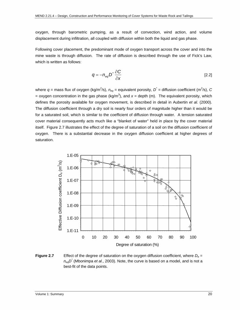
Following cover placement, the predominant mode of oxygen transport across the cover and into the mine waste is through diffusion. The rate of diffusion is described through the use of Fick’s Law, which is written as follows:
xCDnq eq ∂
∂−= * [2.2]
where q = mass flux of oxygen (kg/m2/s), neq = equivalent porosity, D* = diffusion coefficient (m2/s), C = oxygen concentration in the gas phase (kg/m3), and x = depth (m). The equivalent porosity, which defines the porosity available for oxygen movement, is described in detail in Aubertin et al. (2000). The diffusion coefficient through a dry soil is nearly four orders of magnitude higher than it would be for a saturated soil, which is similar to the coefficient of diffusion through water. A tension saturated cover material consequently acts much like a “blanket of water” held in place by the cover material itself. Figure 2.7 illustrates the effect of the degree of saturation of a soil on the diffusion coefficient of oxygen. There is a substantial decrease in the oxygen diffusion coefficient at higher degrees of saturation.
1.E-11
1.E-10
1.E-09
1.E-08
1.E-07
1.E-06
1.E-05
0 10 20 30 40 50 60 70 80 90 100
Degree of saturation (%)
Effe
ctiv
e D
iffus
ion
coef
ficie
nt D
e (m
2 /s)
Figure 2.7 Effect of the degree of saturation on the oxygen diffusion coefficient, where De = neqD* (Mbonimpa et al., 2003). Note, the curve is based on a model, and is not a best-fit of the data points.
Volume 1: Summary 20

MEND 2.21.4 – Design, Construction and Performance Monitoring of Cover Systems for Waste Rock and Tailings
3 SITE CHARACTERIZATION
3.1 Introduction
This manual focuses on site characterization with respect to cover system design. However, it is fundamental to note that comprehensive site characterization should also include a contaminant source assessment, as well as an assessment of existing impacts. Examples of impacts include drawdown of the water table, mounding of a water table, as well as impacts on groundwater or surface water quality due to salinity or ARD. In general, it is typical that during an assessment of current conditions an understanding of the local hydrogeology will be developed, which can then be utilized during the impacts analysis component of the cover system design methodology (see Figure 1.1). An understanding of the local hydrogeology would include hydrostratigraphy, aquifer parameters, direction and hydraulic gradient of groundwater flow, and hydrogeochemistry. These site characterization components are not within the scope of this manual.
Site characterization with respect to the design of cover systems for mine waste requires an understanding of the local natural landforms as well as the mining features such as open pits, waste rock piles, and tailings storage facilities. The available potential cover materials and the objective of the cover system, whether it limits the infiltration of water and/or oxygen, have a large influence on the cover system design. The mine site materials characterization is designed to analyze in situ materials on the mine site and determine if they are suitable for use as a cover material. The objectives of the mine site materials investigation are to classify the types of all potential borrow materials available on site, including benign or “clean” waste material sources and define the horizontal and vertical limits of these deposits.
In general, the materials characterization can be grouped the following categories: 1) compiling and interpreting existing site data, 2) field characterization and sampling, and 3) material testing.
3.2 Compiling and Interpreting Existing Site Data
Preparation of the materials investigation programme should be undertaken one to two months prior to the commencement of field characterization and sampling. Preparation work includes the collection of all existing site data and an initial mine site survey. Each will assist in identifying the appropriate areas in which field sampling test pits should be excavated.
3.2.1 Collection of Existing Data
In North America and many parts of the world, new mining operations or recently developed mining operations have completed environmental impact assessments (EIA). These documents thoroughly investigate pre-existing sub-surface and surface conditions and estimate the characteristics of the mine waste rock piles and tailings storage facilities. The EIA includes data such as the assessment
Volume 1: Summary 21

MEND 2.21.4 – Design, Construction and Performance Monitoring of Cover Systems for Waste Rock and Tailings
of the regional geology, hydrogeology, surface topography and hydrology, climate, and the biological ecosystem.
Environmental impact assessments will not be available at many mine sites; however, most operations have a large amount of historical information. Collection of data such as borehole logs, groundwater piezometer data, and previous reports will assist in identifying the location and type of potential cover materials on the mine site.
Historic climate data collected on the site or at a location near the site is important. The local climate is one of the critical factors influencing the cover system design objectives. It is also very useful for numerical modelling used later in the design process and for comparison to field performance monitoring data once a test or full cover system has been installed.
3.2.2 Initial Mine Site Survey
The initial mine site survey is a quick (less than one day) inspection of the potential cover materials available on the mine site. The survey of the mine site should include personnel with a good knowledge of the mine site materials (e.g. mine site geologists, environmental officers) and the personnel undertaking the mine site materials investigation. The area on which the cover system will be placed should be examined first. An estimate of the size of the area is needed to judge the volume of cover materials required. The potential cover materials, including any suitable waste rock material, should be roughly grouped into the following categories:
• Topsoil – this material is often rich in organic matter and nutrients and is desirable for the top surface of a cover system to assist in reclamation efforts (note however that it is common for topsoil to contain weeds and non-native vegetation, thus making the topsoil undesirable);
• Well-graded material – this material is desirable for use in moisture store-and-release cover systems and can also act as a protection layer in hydraulic barrier and capillary break cover systems;
• Clay or clayey/silty material – this material can be formed into a low hydraulic conductivity barrier; and
• Competent, coarse material – this material can armour the cover system against erosion, especially on sloping surfaces.
The location of each type of material and its distance from the area requiring the cover system should be noted.
In addition to evaluating potential cover materials, the development of a defensible cover system design requires detailed information with respect to the underlying materials. Hence, site characterization will also require sampling of the material to be covered (tailings, waste rock, spent heap leach material) so that hydraulic material properties for these materials can also be determined.
Volume 1: Summary 22
MEND 2.21.4 – Design, Construction and Performance Monitoring of Cover Systems for Waste Rock and Tailings
3.3 Field Characterization and Sampling Programme
A field characterization and sampling programme consists of the excavation of test pits, sample collection for geotechnical and geochemical testing, and the completion of in situ field tests.
3.3.1 Excavation of Test Pits
Excavation of test pits is a relatively straightforward method of material sampling and characterization. The wall of the excavation allows a visual inspection of the material, especially material and moisture variations with depth. As the pits are excavated, material samples can be taken and in situ field testing can be performed at various depths.
Test pits in waste rock and borrow materials are typically excavated using a rubber-tired backhoe. This type of backhoe has the ability to dig through almost all materials and is relatively mobile. If deeper test pits are deemed necessary, then a larger excavator may be required. Sampling of tailings material can also be completed using a backhoe, provided the surface of the tailings is stable. Alternatively, it is common for samples to be collected by augering, which can be done manually, using a small drill rig mounted on a light vehicle, or using a small portable drill rig.
Before excavation, the location of the test pit is recorded (ideally “marked” using GPS) and the desired depth of the test pit and the probable sampling programme is identified. Representative samples are collected for each distinct material type encountered in the test pit. If the material within the test pit is homogeneous, samples are collected at recorded depths. The type and condition of any vegetation in the test pit area should also be recorded to assist with evaluating the material’s suitability as a growth medium. Figure 3.1 shows an excavated trench in oxide waste rock material.
3.3.2 Collection of Samples for Laboratory Characterization
Material samples are generally collected in the field for both geotechnical and geochemical testing purposes. The samples are generally either small or large grab samples, depending on the characterization test to be performed on the sample. For example, samples for particle size distribution and detailed geotechnical testing are typically placed in a number of 20 litre pails, while smaller re-sealable bags are used to collect samples for moisture content and geochemical testing. In general, particles greater than 100 mm are not included in the samples collected for laboratory characterization. Figure 3.2 shows a large-scale field screen, or grizzly, which provides the necessary field control (i.e. less than 100 mm) on the material that is placed into the 20 litre buckets.
It is beneficial to collect duplicate samples during the test pit excavation, even if rigorous testing is not planned. Most of the cost associated with a sampling programme is the earth moving equipment and personnel required to conduct the sampling. The incremental cost to collect duplicate samples for potential physical and geochemical testing offers a significant benefit when weighed against any additional costs associated with re-sampling should it be determined that it is required.
Volume 1: Summary 23

MEND 2.21.4 – Design, Construction and Performance Monitoring of Cover Systems for Waste Rock and Tailings
Figure 3.1 A 2.0 m test pit excavated in waste rock material.
3.3.3 In Situ Field Tests
The in situ field tests include paste pH / paste conductivity, gravimetric moisture content, field hydraulic conductivity, density, and determination of the Munsell colour. Visual test pit logs are recorded as the test pits are developed. Details regarding these test procedures are given in Volume 3.
Paste pH test results provide an indication of the current state of acidity in the samples, while the paste conductivity test results provide an indication of the total soluble solids associated with the sample. The tests indicate whether oxidation and accumulation of potentially leachable contaminants have occurred in the potential cover or waste material. Materials with low field paste pH and high conductivity are, in general, not considered to be adequate cover materials. Paste pH / paste conductivity tests are not a substitute for a proper geochemical characterization programme; however, in concert with standard field observations during a site investigation (e.g. colour, lithology, sulphide content, evidence of oxidation of secondary mineralogy, vegetation, venting, seepage and/or surface water quality, and fish and biota conditions) they are a good indicator of which samples should be submitted for further detailed geochemical testing.
Volume 1: Summary 24
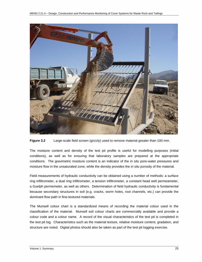
MEND 2.21.4 – Design, Construction and Performance Monitoring of Cover Systems for Waste Rock and Tailings
Figure 3.2 Large-scale field screen (grizzly) used to remove material greater than 100 mm.
The moisture content and density of the test pit profile is useful for modelling purposes (initial conditions), as well as for ensuring that laboratory samples are prepared at the appropriate conditions. The gravimetric moisture content is an indicator of the in situ pore-water pressures and moisture flow in the unsaturated zone, while the density provides the in situ porosity of the material.
Field measurements of hydraulic conductivity can be obtained using a number of methods: a surface ring infiltrometer, a dual ring infiltrometer, a tension infiltrometer, a constant head well permeameter, a Guelph permemeter, as well as others. Determination of field hydraulic conductivity is fundamental because secondary structures in soil (e.g. cracks, worm holes, root channels, etc.) can provide the dominant flow path in fine-textured materials.
The Munsell colour chart is a standardized means of recording the material colour used in the classification of the material. Munsell soil colour charts are commercially available and provide a colour code and a colour name. A record of the visual characteristics of the test pit is completed in the test pit log. Characteristics such as the material texture, relative moisture content, gradation, and structure are noted. Digital photos should also be taken as part of the test pit logging exercise.
Volume 1: Summary 25

MEND 2.21.4 – Design, Construction and Performance Monitoring of Cover Systems for Waste Rock and Tailings
3.4 Laboratory Characterization Programme
The laboratory characterization programme for most comprehensive cover design studies involving reactive mine waste will consist of a geotechnical and a geochemical component.
3.4.1 Recommended Geotechnical Testing Programme
The geotechnical laboratory test programme is generally completed on both the potential cover material and mine waste material samples. The programme is designed to determine physical and hydraulic parameters of the materials for input to soil-atmosphere cover system design and numerical models. A comprehensive geotechnical characterization programme would consist of laboratory tests to determine the following parameters:
• Particle size distribution (PSD);
• Atterberg limits (and possibly X-ray diffraction to assist with determining clay mineralogy);
• Specific gravity;
• Compaction curve (i.e. Proctor curve);
• Saturated hydraulic conductivity;
• Consolidation-saturated permeability relationship; and
• Soil water characteristic or moisture retention curve.
Some of the tests, such as PSD and Atterberg limits, are well known and can be completed by almost all geotechnical engineering testing firms. Other tests, such as the hydraulic conductivity and moisture retention tests, are specialized and performed by only a small number of laboratories. A description of the various geotechnical laboratory tests is provided in Volume 3.
3.4.2 Recommended Geochemical Testing Programme
A detailed geochemical testing programme is generally performed on samples of reactive mine waste to determine the current and potential long-term geochemical characteristics of the waste material. Simple geochemical laboratory tests, such as paste pH and conductivity analyses, would generally be performed on potential cover material samples to ensure that the material is suitable for use in the cover system design from a surface water quality perspective.
A more comprehensive geochemical characterization programme would include, but is certainly not limited to, the following laboratory tests:
• Paste pH and conductivity analyses – largely to serve as QA/QC for field measurements;
• Modified Acid Base Accounting (ABA) tests – which consist of total sulphur analyses and acid neutralization capacity titrations;
Volume 1: Summary 26
MEND 2.21.4 – Design, Construction and Performance Monitoring of Cover Systems for Waste Rock and Tailings
• Static Net Acid Generation (NAG) tests – which, together with the results of the ABA tests, provide a refined classification of the potential for acid generation;
• Kinetic Net Acid Generating (NAG) tests – if a better understanding of the time dependent oxidation processes are deemed necessary;
• Leach extraction tests – to provide an indication of the pore-water chemistry and soluble content associated with the samples;
• Forward acid titration tests (also termed acid buffering characteristic curves) – to provide an indication of the pH ranges in which buffering is available; and
• Multi-element ICP whole rock analysis – to provide an assessment of the heterogeneity of the materials.
A description of the tests and additional references are given in Volume 3.
Volume 1: Summary 27

MEND 2.21.4 – Design, Construction and Performance Monitoring of Cover Systems for Waste Rock and Tailings
4 CONCEPTUAL COVER SYSTEM DESIGN
4.1 Introduction
Following a site characterization, the next stage in the development of a cover system is the conceptual cover system design. Defining the cover system objectives is the first step in the design of the conceptual cover system, as discussed in Section 1. Once the objectives are defined, then a type of cover system is chosen from a conceptual perspective on the basis of site specific factors such as climate and available materials. To evaluate different types of cover systems against the defined cover system objectives, numerical modelling tools are often used to predict performance.
4.2 Conceptual Design
The conceptual cover design must be chosen based on the materials available, the climate, and the objectives of the cover. It is critical that the conceptual cover design is tailored to the characteristics of the specific site and not chosen based solely on the design having “worked at another site”.
Site characterization defines the available materials and climate. Once the candidate cover materials are known, the type of cover system design best suited to the site can be evaluated based on interpretation of the laboratory test results, as well as the site’s climate conditions. The results of the laboratory tests can be interpreted to determine whether suitable materials to meet these criteria, and of sufficient volume, are available at the site. In the event this is not the case, or it is not clear whether the material is suitable, then alternate cover system design scenarios may need to be developed and included in the preliminary numerical modelling evaluation, as discussed in subsequent sections.
For example, if a site is located in a humid environment with an annual moisture surplus (i.e. precipitation is similar to or greater than potential evaporation), then it could be assumed that one of the layers of the cover system will likely need to possess low hydraulic conductivity to function as a “barrier” to water infiltration. In addition, a material suitable as a growth medium will be required above this layer to allow for establishing a sustainable vegetation cover, as well as to provide a means of satisfying the demand for moisture from evapotranspiration during the inevitable dry summer periods.
The objective during the conceptual cover system design stage is to “match” the site’s climate conditions with the available potential cover materials, and develop feasible design alternatives prior to conducting any numerical modelling. Consideration for the chemical, physical, and biological processes that could alter the laboratory measured or assumed properties of the cover material (e.g. saturated hydraulic conductivity), and thus impact on long-term performance of the cover system must be included in this conceptual cover system design stage. This aspect of the conceptual cover system design stage is fundamental to ensuring that a potentially fatal flaw in the design is not
Volume 1: Summary 28

MEND 2.21.4 – Design, Construction and Performance Monitoring of Cover Systems for Waste Rock and Tailings
introduced. Finally, consideration for construction issues (e.g. constructability, complexity, difficulty with quality assurance / control) must also be included in the conceptual cover system design stage.
4.2.1 Alternate Cover System Designs
Figure 4.1 shows the base method cover system design as well as variations of the base method. The purpose of discussion in this section is to help mine personnel understand the alternate cover system designs typically evaluated. However, due to the complexity of the design and evaluation process it would be expected that professionals working in this area would undertake the detailed work required to evaluate the alternatives.
Base Method I II
III
IV
V
Variations on the Base Method
CapillaryBarrier
CapillaryBarrier
WasteMaterial
Compacted
Native Materialor
Barren Wasteor
Oxidized WasteCover Material
WasteMaterial
"Alternate"Cover
Material
Native or
Barren or
Oxidized Cover
WasteMaterial
CapillaryBarrier
Native or
Barren or
Oxidized Cover
Waste Material
Native or
Barren or
Oxidized Cover
Waste Material
Native or
Barren or
Oxidized Cover
WasteMaterial
Compacted
Native or
Barren or
Oxidized Cover
Figure 4.1 Schematic illustration of the base method cover system and variations of the base method (adapted from Swanson et al., 1999).
Numerous combinations of the variations presented in Figure 4.1, could be evaluated, but in the interest of clarity only the basic variations are shown. The simplest case (i.e. the base method cover system design) is typically evaluated first during the conceptual and /or preliminary cover system design phase, and then complexity added until the desired design objectives are met. In general, increasing complexity in the design of a cover system implies increased cover system performance, but would also typically entail increased costs and a more difficult cover system to construct. Note however, that an increase in performance is not necessarily true for all climate conditions. For example, a moisture store-and-release cover system in arid or semi-arid climate conditions can provide the same level of control on net percolation as compared to a cover system with a low hydraulic conductivity barrier layer or a capillary barrier cover system.
Volume 1: Summary 29

MEND 2.21.4 – Design, Construction and Performance Monitoring of Cover Systems for Waste Rock and Tailings
Factors that control the economic and technical feasibility of a cover system for a particular site include, but are certainly not limited to:
• site climate conditions;
• availability of cover material(s) and distance to borrow source(s);
• cover and waste material properties and conditions;
• surface topography;
• soil and waste material evolution; and
• vegetation conditions.
“Barren waste” in the subsequent discussion of alternate cover system designs is considered to be non-reactive waste rock or tailings. This material is not considered as a “special cover material”, but rather a logical cover material source available to most, if not all, mine sites. “Oxidized waste cover material” is considered to be near surface waste rock that at one time contained sulphide minerals, but now is free of sulphides and oxidation products through natural weathering over geologic time.
The base method and variations of the base method were presented in MEND 5.4.2d and are discussed below.
1) Base Method – Non-compacted cover material placed directly on the waste material. This material is usually native material, barren waste material, or oxidized waste material. The primary objective of this cover system is establishment of a sustainable vegetation cover, although reduction of net percolation could also be viewed as a prime objective. This design is most commonly used to cover waste materials that are non-reactive.
2) Base Method Variation I – Non-compacted cover material placed directly on the waste material, but with an increase in the thickness of the non-compacted material. This cover system is an attempt to increase the ability of the cover system to reduce net percolation of moisture to the underlying waste by increasing the available moisture storage capacity (i.e. store and release of moisture). Establishing a sustainable vegetated cover is also an objective.
3) Base Method Variation II – A capillary barrier material is placed directly on the underlying waste and overlain by non-compacted material. The primary objective of including the capillary barrier material is to provide a hydraulic discontinuity between the underlying waste and the overlying non-compacted cover material. The capillary barrier material is typically added if potential exists for capillary rise of contaminants (i.e. process water and/or oxidation products) to impact the sustainability of vegetation or the quality of surface water.
Volume 1: Summary 30

MEND 2.21.4 – Design, Construction and Performance Monitoring of Cover Systems for Waste Rock and Tailings
4) Base Method Variation III – A compacted layer is placed directly on the underlying waste and overlain by the non-compacted material. The objective is to provide a hydraulic barrier to percolation of water due to the low hydraulic conductivity of the compacted material. In addition, the compacted material will typically have the ability to retain moisture under significant drainage and evaporative conditions. Hence, a barrier to oxygen ingress can be achieved by the presence of the compacted material because of the high saturation levels maintained in the compacted layer. The compacted material can consist of native material, run-of-mine waste material (barren or oxidized), or tailings (inert or desulphurized). The upper layer of non-compacted material will store and release moisture as well as provide a medium for vegetation development.
5) Base Method Variation IV – An alternate cover material is placed on the underlying waste and overlain by non-compacted material. The alternate cover material can be an organic layer of material such as municipal solid waste compost, wood waste, peat, etc. These materials have the potential to provide physical barriers to oxygen ingress (i.e. high saturation layers) but also to consume atmospheric oxygen through decomposition. These materials also have the potential to function as vegetation growth mediums, thereby limiting the requirement for the non-compacted native material. The alternate material can also consist of synthetic materials such as cementitious material, shotcrete, flyash mixtures, geopolymers, flexible membrane liners such as geomembranes and geosynthetic clay liners, and ameliorated cover material barriers where bentonite (with or without polymers) or flyash are added to enhance performance of the compacted cover material.
6) Base Method Variation V – This variation of the base method cover system design includes a capillary barrier material placed directly on the waste material, as shown in Figure 4.1. The capillary barrier material is usually a uniform material (i.e. like beach sand) that is coarser in texture than the compacted material. A compacted layer and an upper capillary barrier material then overlie the lower capillary barrier material. The three layers are typically overlain by a vegetation growth medium. It can be feasible for the upper capillary barrier material to act as a growth medium if the compacted material has significant fines and moisture retention, thus allowing the overlying capillary barrier material to be finer textured and function as a zone for root development.
4.3 Approach to Numerical Modelling
Predicting the performance of cover systems using numerical modelling should use a philosophy that integrates the waste material within its environmental context. This is in contrast to attempting to isolate the waste from the environment to completely prevent the production and release of sulphide oxidation products. The cover system must be designed as an unsaturated system exposed to the atmosphere, where cover system performance is significantly influenced by daily, seasonal, annual, and long-term site climate conditions. An approach that attempts to completely “isolate” potentially
Volume 1: Summary 31
MEND 2.21.4 – Design, Construction and Performance Monitoring of Cover Systems for Waste Rock and Tailings
net acid forming mine waste from the environment is based on the somewhat flawed viewpoint of considering an engineered cover system as an “upside down liner”. This latter philosophy would greatly increase the potential for long-term performance problems in almost all situations.
The key issues governing the use and applicability of modelling tools relate to defining the input required for the model and understanding the key output. These issues not only affect the choice of model best suited for the application, but also the site and material information required prior to evaluating the designs.
4.3.1 Processes
All models operate under the same fundamental principles: solving a set of equations that describe physical processes subject to boundary conditions and material behaviour (material properties). The physics govern which processes are occurring in the system, the boundary conditions set limits on the problem, and the material properties change the way the physical processes act.
In evaluating cover system performance, the physics that are involved are typically limited to:
• Movement of air: this includes advection and diffusion processes and includes the flow of oxygen or other gases of interest;
• Movement of water: this includes percolation of liquid water (advection) as well as evaporation (movement of water vapour), and transpiration;
• Solute movement: this includes both advective and diffusive movement of contaminants;
• Adsorption of water vapour or contaminants;
• Decay or reaction, such as the oxidation of sulphide minerals; and
• Heat transfer, such as freeze-thaw or internal heat generation.
Not all of these processes are involved in every system. Often, the physics modelled are limited to the movement of air and water.
4.3.2 Input
The boundary conditions set limits on the problem and force the physical processes to behave in certain ways. The key boundary conditions for cover system modelling are:
• Upper boundary conditions: climate and vegetation;
• Lower boundary conditions: hydrogeology; and
• Initial conditions.
Volume 1: Summary 32

MEND 2.21.4 – Design, Construction and Performance Monitoring of Cover Systems for Waste Rock and Tailings
Material properties are usually based on some key measurable properties such as porosity, specific gravity, saturated hydraulic conductivity, and the SWCC.
Once the input has been defined, a method of solution must be chosen. The term “modelling” has become synonymous with commercially available software packages but the method of solution may be analytical or numerical, one-dimensional or multi-dimensional, and can be as simple as a single formula or complex as a three-dimensional finite element model.
4.3.3 Output
The output from numerical modelling is directly related to the cover system performance criteria, which relates back to the cover system objectives. Typically, the key outputs from the numerical model are fluxes: both oxygen and water fluxes.
In general, the output used for determining the preferred cover system design for a given site is the predicted net percolation to the underlying waste. Control of oxygen ingress throughout the year may also be a basis for determining the preferred cover system design for certain areas, depending on the prevalent site climate conditions. It is important to note, however, that control of oxygen ingress may not be technically or practically feasible at all sites due to significant dry climate conditions for an extended period of the year. Despite this, oxygen ingress should always be modelled / predicted as part of the cover system design process such that the data can be used during geochemical speciation modelling of the underlying waste.
Lastly, it is fundamental that the performance of the cover system is “linked” to predicted seepage from the waste storage facility and ultimately to the impact on surface water and groundwater. This fundamental concept incorporates the scope of the cover system and provides the necessary rationale for determining the required reduction in net percolation and / or control in oxygen ingress for the cover system.
4.3.3.1 Defining Net Percolation
Net percolation, as shown conceptually in Figure 4.2, is the net result of meteoric water infiltrating into the cover material surface. Meteoric water will either be intercepted by vegetation, runoff, or infiltrate into the surface. Water that infiltrates will be stored in the “active zone” and may then subsequently exfiltrate back to the surface and evaporate, or be removed by transpiration. A percentage of the infiltrating meteoric water will migrate beyond the active zone as a result of gravity overcoming the influence of atmospheric forcing (i.e. evaporation), and result in net percolation to the underlying waste.
Volume 1: Summary 33

MEND 2.21.4 – Design, Construction and Performance Monitoring of Cover Systems for Waste Rock and Tailings
Net SurfaceInfiltration
OxygenIngress
LateralPercolationand Interflow
Runoff
Rain
AET
CoverMaterial
WasteMaterial
Atmosphere
Net Percolationto Waste Rock
( S)Change in
Moisture Storage
∆
Figure 4.2 Conceptual illustration of net percolation.
4.4 Numerical Modelling Methodologies
There are many tools available to aid in the analysis and design of cover systems. The tools, including the experiences of the user, have varying capabilities and limitations. It is up to the designer to understand the theoretical premise each tool is based on and, with a design objective in mind, apply the tool in a methodical way so that there is a reasonable assurance the generated output is representative of “real life” possibilities.
The advantage of numerical modelling is that it allows for coalescing and evaluating a set of complex settings, processes, designs, and decisions into a comprehensive effort. The purpose for numerical modelling in general is threefold.
1. Modelling can be conducted to interpret a mechanism or process (e.g. to prove a hypothesis or to “train” our thinking), or to assist with interpretation of field data;
2. Modelling can be used to evaluate the relative performance of alternate conditions; and
3. Modelling can be used for predicting a final behaviour or impact.
In general, the latter two aspects tend to be the focus of numerical modelling, when in fact the first rationale should be the foremost use of a numerical model. For example, numerical modelling is often dismissed as being “useless” due to a lack of predictive accuracy. However, the key advantage to numerical modelling is the ability to enhance judgement, not the ability to enhance predictive capabilities. In short, numerical modelling should focus on improving our ability to understand key processes and characteristics, as opposed to enhancing predictive capability. Numerical modelling should be undertaken at all levels of the project (e.g. data gathering, interpretation, and design), and not just for predicting performance.
Volume 1: Summary 34

MEND 2.21.4 – Design, Construction and Performance Monitoring of Cover Systems for Waste Rock and Tailings
A general objective of modelling is to obtain computed data that represents what may reasonably happen under a specific set of conditions. Reasonableness however, should not be confused with accuracy or reliability. A computer can be precise to the tenth decimal place but this should not imply the prediction is accurate.
It is primarily the knowledge and skill of the user that determines if and when results are reasonable. The most common mistake with numerical modelling is for the user to accept the results without question, without having a fundamental understanding of the physical system being modelled, the theoretical foundation for the model, and the limitations of the model. The most straightforward approach to obtaining reasonable results is to follow a proven methodology.
The key components of a numerical modelling methodology are analogous to the scientific method, or the engineering approach to solving a problem, as shown in Table 4.1.
Table 4.1 Modelling parallels to the scientific method
Scientific Method
Engineering Approach Modelling
Observe Definition of the problem. Development of the conceptual model.
Measure What processes are occurring? Define the theoretical model.
Explain What does the system involve? Obtain the numerical model (develop an accurate solution).
Verify Does the solution agree with measured conditions or intuition?
Resolve the interpretive modelling results (prove the hypothesis, does the interpretive model represent reality, or do you need to
change your thinking?)
4.4.1 Purpose and Scope of Cover Design Modelling
The general purpose for conducting cover system design modelling is to gain an understanding for the key processes and characteristics that will control performance. In addition, the cover system design numerical modelling will provide the means to evaluate the conceptual or preliminary design of a cover system for the site waste storage facilities in terms of meeting the cover system design objectives. The cover system design and analysis would typically consist of one-dimensional soil-atmosphere modelling and two-dimensional saturated-unsaturated modelling.
In general, the objectives of the one-dimensional (1D) soil-atmosphere modelling are to:
• compare performance of alternate designs (i.e. single layer cover systems, multi-layer cover systems, variations in layer thickness);
• predict the net percolation of moisture to the underlying waste material; and
Volume 1: Summary 35

MEND 2.21.4 – Design, Construction and Performance Monitoring of Cover Systems for Waste Rock and Tailings
• evaluate the ability of the alternate cover systems to limit the ingress of atmospheric oxygen to the underlying waste material.
The objective of any two-dimensional (2D) saturated-unsaturated modelling is to assess the performance of the preferred cover system design on the side-slopes of the waste storage facility, or to evaluate the impact of runoff and run-on and ponding on a horizontal or sloping cover system.
4.4.2 Application of the Modelling Methodology
The soil-atmosphere modelling methodology presented in this manual includes a preliminary soil-atmosphere modelling stage, a detailed soil-atmosphere modelling stage, and a sensitivity soil-atmosphere modelling stage. Once a cover system has been constructed, whether it is full scale or at a test scale, field response and predictive modelling should be conducted. The following sections summarize the objectives of the modelling stages. A more detailed discussion of the modelling stages and some example modelling results are presented in Volume 3.
4.4.2.1 Preliminary Modelling (1D)
The preliminary modelling can be conducted to determine the proper lower boundary condition (LBC) and thickness of the underlying waste material for use in more advanced models. The objective is to ensure that the location and magnitude of the LBC does not influence the net percolation or oxygen ingress predicted by the model from the cover material to the underlying waste material.
The preliminary modelling can also be used to:
• verify fundamental processes;
• identify limitations of the model and its application to the problem at hand;
• develop modifications to the model to make it more suitable for the problem;
• identify key input parameters; and
• redefine the laboratory characterization or field characterization programme.
The initial moisture and temperature conditions for subsequent detailed modelling can also be generated during the preliminary modelling component of the project. Successive models can be completed using the end-of-simulation moisture and temperature conditions as the initial conditions for a subsequent model. This approach should be repeated until the change in moisture storage within the cover system is constant, which implies that the initial conditions of the detailed models, while representative of site conditions, did not influence the results of the detailed models. This will allow for a quantitative comparison between the results generated by each of the detailed soil-atmosphere models.
Volume 1: Summary 36

MEND 2.21.4 – Design, Construction and Performance Monitoring of Cover Systems for Waste Rock and Tailings
The preliminary modelling should also be used to determine which cover system alternatives had the best opportunity for success, where “success” refers to the ability of the cover system to meet the design objectives, such as reducing net percolation and oxygen ingress. This often involves varying the thickness and layering of the available cover materials. In general, a “synthetic” average climate year and “average” material properties for each cover material and the underlying waste are used during the preliminary modelling stage. The “synthetic” average climate year is obtained by averaging each daily climate input parameter for the entire period of record. For example, rainfall on January 1st of the synthetic average climate year would be the average of all January 1st data for each year of the available climate record. The objective is to “smooth” the modelling process by eliminating high rainfall and other extreme climate conditions such that numerical instability and water balance modelling problems are greatly minimized.
4.4.2.2 Detailed Modelling (1D)
The objective of the detailed modelling stage is to determine the most reasonable or “average” predicted performance of the cover system with respect to net percolation and oxygen ingress, which would then be used as input to seepage and/or groundwater models. Determining the average performance can seem like a simple task. For example, the climate year that is close to the average annual precipitation could be chosen to predict the average net percolation from the cover system. However, a word of caution is required with respect to utilizing this approach. The net percolation predicted from the mean or median rainfall record for a given site may not be representative of the long-term “average” performance of a cover system. The magnitude and occurrence of various rainfall events throughout the year, coupled with antecedent moisture conditions, plays a major role in the computation of the net percolation through a cover system. Therefore, evaluating long-term “average” cover system performance using the mean climate year may in fact result in a predicted net percolation that is not representative of the “average” net percolation.
The long-term “average” performance of a cover system should be determined from a statistical analysis of the net percolation predicted for each year of the climate record. The latter methodology accounts for the impact of antecedent moisture conditions, as well as the occurrence and intensity of daily rainfall when determining the long-term “average” net percolation.
Another benefit to the statistical approach is the ability to develop a statistical basis for extreme dry and extreme wet climate years. As with determining the average year, it is fundamentally incorrect to simply model the wettest year on record. That particular year may be the wettest year because of one or possibly two significant short duration high frequency rainfall events. Runoff during these events is significant, which may result in a misrepresentation of a more representative extreme climate condition. Determining the net percolation for each year of record provides the necessary data for calculating net percolation values for different return periods, which can then be used for seepage and groundwater modelling. The same process can also be used for oxygen ingress.
Volume 1: Summary 37

MEND 2.21.4 – Design, Construction and Performance Monitoring of Cover Systems for Waste Rock and Tailings
4.4.2.3 Sensitivity Modelling (1D)
A sensitivity analysis with respect to material properties and climate conditions should be conducted on the most promising alternative(s) to confirm performance for various scenarios. The sensitivity analysis will also allow for the development of an understanding of the impact on performance due to:
• extreme climate conditions;
• long-term climate changes; and
• changes with in situ conditions and material properties due to biological, physical, and chemical processes, which will impact on long-term performance.
4.4.2.4 Two-Dimensional Modelling (2D)
One-dimensional modelling has limitations for simulating sloping surfaces and associated runoff and run-on, ponding, as well as lateral and preferential flow. Sloping surfaces are characteristic of waste rock surfaces, heap leach piles, and tailings dam walls as a result of construction methods and placement configurations. A hummocky cover placement also creates a sloping surface that is not well represented by a 1D model. Volume 2 – Theory and Background discusses preferential flow in greater detail.
The objectives of two-dimensional modelling are to examine the impact of sloping surfaces on the flow patterns of infiltration for changing cover materials and material thickness. Two-dimensional modelling consists of both steady-state and transient analyses. The objective is to ensure that the impact of the slope angle, slope length, properties of the cover and waste materials, as well as site specific climate conditions are properly addressed to ensure that the cover system has not been designed as a 1D system, and placed into a 2D condition. The design of a cover system as a 1D system, which is then placed on a sloping surface in a humid or semi-humid climate, often leads to a “fatal flaw” with respect to in situ hydraulic performance (i.e. control of net percolation and/or oxygen ingress).
4.5 Landform / Landscape Engineering
The scope of this manual is limited to cover system design, construction, and performance monitoring. However, it should be noted that a key component of long-term performance is the development of a sustainable landform that addresses issues such as surface water hydrology, watershed management, erosion, vegetation, and other aspects of landscape engineering. This area of mine closure planning is an emerging technology, which has received greater attention in the past at sites located in Australia, but is now being seen as a critical closure planning issue at many sites in Canada.
Volume 1: Summary 38

MEND 2.21.4 – Design, Construction and Performance Monitoring of Cover Systems for Waste Rock and Tailings
In general, the issues typically associated with landform / landscape engineering are not within the scope of this document, although the issues are addressed conceptually in Sections 6 and 7. For additional details and information the reader is referred to (Evans, 1997; Hancock et al., 2000; Hancock et al., 2002; Hancock et al., 2003 (in press); Hancock, 2003 (in press); McKenna, 2002; Willgoose, 1994 and 1995; Willgoose and Riley, 1993; Willgoose et al., 1989). Further information on vegetation in cover design can be found in MEND 2.24.1.
Volume 1: Summary 39

MEND 2.21.4 – Design, Construction and Performance Monitoring of Cover Systems for Waste Rock and Tailings
5 FIELD PERFORMANCE MONITORING
Direct measurement of field performance is the state-of-the-art methodology for measuring performance of a cover system. Field performance monitoring can be implemented during the design stage with test cover plots (e.g. Aubertin et al., 1997a; O’Kane et al., 1998a, 1998b), or following construction of the full-scale cover (e.g. MEND 2.22.4a,b; O’Kane et al., 1998c). Direct measurement of field performance of a cover system is the best method for demonstrating to regulatory agencies and the public that the cover system will perform as designed. The main objectives of field performance monitoring are to:
• Obtain a water balance for the site;
• Obtain an accurate set of field data to calibrate a numerical model;
• Develop confidence with all stakeholders with respect to cover system performance; and
• Develop an understanding for key characteristics and processes that control performance.
The desired field performance monitoring system should include monitoring of the various components of the water balance that influence the performance of a cover system. These components are shown schematically in Figure 5.1. MEND (2000) provides a detailed overview of field performance monitoring for cover systems.
In terms of a research scale, or a field test plot trial scale, cover system field performance monitoring systems should be designed to measure most of the components of the water balance as well as oxygen ingress rates, as shown schematically in Figure 5.1. This includes meteorological monitoring, monitoring of moisture storage changes, and monitoring of net percolation, surface runoff, erosion, and vegetation.
In terms of field performance monitoring for a full-scale cover system, a recommended minimum level of monitoring would include meteorological monitoring (i.e. determination of the potential evaporation), site specific precipitation, cover material moisture storage changes, watershed or catchment area surface runoff, vegetation, and erosion.
Volume 1: Summary 40

MEND 2.21.4 – Design, Construction and Performance Monitoring of Cover Systems for Waste Rock and Tailings
SurfaceEvaporation
∆ Storage
WASTE ROCK
RunoffCOVER SOIL
Root WaterUptake
TranspirationAET
Precipitation
Oxygen Ingress
Interflow
Net Percolation
Net Infiltration
Lateral Percolation
Figure 5.1 Conceptual schematic of the components of a field performance monitoring system.
Table 5.1 lists typical methods of measurement for the various components of a field performance monitoring system. Methods for measuring precipitation, actual evapotranspiration, in situ moisture conditions (moisture content and soil suction), net percolation, and surface runoff / erosion are discussed in Volume 4. The majority of the information provided below is taken from Ayres (1998) and O’Kane (1996).
Volume 1: Summary 41
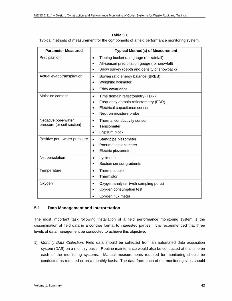
MEND 2.21.4 – Design, Construction and Performance Monitoring of Cover Systems for Waste Rock and Tailings
Table 5.1 Typical methods of measurement for the components of a field performance monitoring system.
Parameter Measured Typical Method(s) of Measurement
Precipitation • Tipping bucket rain gauge (for rainfall) • All-season precipitation gauge (for snowfall) • Snow survey (depth and density of snowpack)
Actual evapotranspiration • Bowen ratio energy balance (BREB) • Weighing lysimeter
• Eddy covariance
Moisture content • Time domain reflectometry (TDR) • Frequency domain reflectometry (FDR) • Electrical capacitance sensor • Neutron moisture probe
Negative pore-water pressure (or soil suction)
• Thermal conductivity sensor • Tensiometer • Gypsum block
Positive pore-water pressure • Standpipe piezometer • Pneumatic piezometer • Electric piezometer
Net percolation • Lysimeter • Suction sensor gradients
Temperature • Thermocouple • Thermistor
Oxygen • Oxygen analyser (with sampling ports) • Oxygen consumption test
• Oxygen flux meter
5.1 Data Management and Interpretation
The most important task following installation of a field performance monitoring system is the dissemination of field data in a concise format to interested parties. It is recommended that three levels of data management be conducted to achieve this objective.
1) Monthly Data Collection: Field data should be collected from an automated data acquisition system (DAS) on a monthly basis. Routine maintenance would also be conducted at this time on each of the monitoring systems. Manual measurements required for monitoring should be conducted as required or on a monthly basis. The data from each of the monitoring sites should
Volume 1: Summary 42

MEND 2.21.4 – Design, Construction and Performance Monitoring of Cover Systems for Waste Rock and Tailings
then be evaluated as a whole, as well as for each individual sensor, to ensure that all DASs and individual sensors are functioning properly and responding to atmospheric forcing as anticipated.
This monthly effort is utilized to address a common mistake with respect to field performance monitoring systems. That is, if field data is not reduced and quality control checks not performed until an extended period has elapsed, the potential exists that a malfunctioning sensor (or sensors) will not be discovered. The potential result is that key field data will be lost, even though a significant financial commitment has been made to obtain the field data.
2) Quarterly Field Performance Monitoring Reports: It is also recommended that field performance monitoring reports be prepared on a quarterly basis for at least the first two years of monitoring. These reports would typically include:
• A summary of data capture rates and an evaluation of individual sensors;
• Presentation of the field data in a concise format;
• A discussion and summary of performance for each monitoring site, which would focus on the quarterly monitoring period; and
• Recommended maintenance.
As field performance monitoring extends past the first two to three years, and an understanding for the system is developed, the frequency of the field performance monitoring can be adjusted to reflect the information requirements for long term field performance monitoring. At no point should the monthly quality control checks and maintenance be discontinued if the site plans to continue to utilize the data for future analysis and interpretation. Long term performance monitoring, such as the 17 years of monitoring at Rum Jungle, has shown that a commitment to data collection is critical factor in verifying the performance of a cover system.
3) Annual Field Performance Monitoring Reports: The annual field performance monitoring report would represent the fourth quarterly report in a given annual monitoring period. This report would be organized as noted above for the quarterly performance monitoring reports. However, the discussion and summary would focus on the entire year of field data. In addition, a more detailed set of field data would be presented.
Ideally, a computer database should be developed to manage the field data obtained from a cover system performance monitoring system. This software would typically be available to all individuals requiring access to the field data. The database would be designed to respond to queries selected by the user, which are a reflection of the individual’s needs. For example, the user may query for moisture conditions at a specific location and depth over a range of dates, and then overlay the resulting information with related influential factors such as precipitation. This data could be presented in a tabular or chart format. The user could then export the data or chart to an alternate software package as required.
Volume 1: Summary 43
MEND 2.21.4 – Design, Construction and Performance Monitoring of Cover Systems for Waste Rock and Tailings
6 CONSTRUCTION ISSUES
There are many issues pertaining to cover construction that are fundamental to long term cover performance, many of which are atypical when compared to other types of construction. It is fundamental that the cover system is constructed with good quality control to ensure that the completed cover system is representative of the actual cover design. The impact of improper construction of a cover system, or poor quality assurance and control during construction, can have a significant, if not dominant influence on cover system longevity. It can be argued that poor construction of a cover system is the most important factor negatively influencing long-term cover system performance.
For example, the thickness of a growth medium overlying a compacted layer may be appropriately designed and specified. However, if it is not constructed to the proper specifications, then significant potential exists for the saturated hydraulic conductivity of an underlying compacted layer to increase, which would result in a reduction in the long-term performance of the cover system.
The following is a summary of construction issues that should be considered prior to constructing the cover system. Construction issues vary with each individual mine site depending on the local climate, the materials being used, the equipment available, and many other factors. The following discussion highlights some, but definitely not all, construction issues relating to cover placement.
6.1 Growth Material Layer Thickness
Often in the design and construction of a compacted barrier layer – growth medium cover system, the focus of the design is on the compacted barrier layer. Considerable attention is paid to the placement of the compacted layer, ensuring proper water content and compaction to produce a low hydraulic conductivity material. Less attention is typically paid to the growth medium layer. The growth medium layer serves as a means of integrating the cover system into the ecosystem that will establish at the site while allowing the underlying compacted layer to “withstand” physical processes, such as wet / dry cycling and freeze / thaw cycling, as well as chemical and biological processes. An inadequate growth medium layer has the potential to lead to improper integration of the cover system into the eco-setting, which will then result in changes in performance to the underlying barrier layer. Concurrent to these considerations is that the growth medium must possess sufficient available water holding capacity to ensure a sustainable vegetation cover, which would be a function of the site-specific climate conditions, the underlying compacted material, as well as the moisture retention and thickness of the growth medium.
6.2 Cover Layer Compaction Issues
It is common for cover systems to incorporate a compacted layer or require compaction of the materials as they are placed. Even store-and-release cover layers, although not designed as a
Volume 1: Summary 44
MEND 2.21.4 – Design, Construction and Performance Monitoring of Cover Systems for Waste Rock and Tailings
“barrier” to flow, require care during placement to obtain the desired homogeneity, porosity, hydraulic conductivity, and control for minimizing segregation. Successful construction of the compacted layer of a cover system involves many factors including: selection of materials; assessment of chemical compatibility; determination of construction methodology; analysis of slope stability and bearing capacity; evaluation of subsidence; consideration for environmental factors; and development and execution of a construction quality assurance and control plan. In general, the rationale behind including a compacted layer in a cover system is to create a layer of material with a sufficiently low hydraulic conductivity (to control net percolation), and appropriate moisture retention characteristics (to control oxygen ingress). The key factors that affect the hydraulic material properties of an engineered compacted material are the density and moisture content. The relationship between density and moisture content can be determined from the compaction characteristics of the material.
6.2.1 Compaction Characteristics
The moulding water content and the dry density are the two key parameters that must be controlled during material placement and compaction, assuming that the required material is being used for construction and the underlying surface has been prepared properly. A compaction (or Proctor) test is conducted in the laboratory to develop a compaction curve for a given material, which is a plot of dry density versus water content. The moulding water content is the water content at which the soil matrix is compacted. Small amounts of water reduce the negative pore fluid pressures, and reduce the effective stress, which enables the soil to be more tightly packed. The addition of an increased amount of water eventually creates positive pore pressures, thus decreasing effective stress and limiting the achievable density at a particular level of compaction. A relationship between dry density and moulding moisture content can be developed, as shown in Figure 6.1a, if the unit weight of water is subtracted from the total unit weight. Figure 6.1a shows that for a particular level of compaction effort there is a maximum level of dry density that can be obtained. The moulding water content providing this optimum or maximum level of density is referred to as the optimum moulding water content (OMC).
To simplify the discussion, a modified Proctor curve is discussed for a generic clay cover material. The modified proctor and hydraulic conductivity curves versus moulding water content are the result of compacting six different portions (sub-samples) of a sample over a range of water contents. Each of the six sub-samples are indicated in Figures 6.1a and 6.1b. Sub-sample 1 represents the driest and sub-sample 6 the wettest moulding water content. Sub-sample 3 has the greatest dry unit density and thus represents the OMC. The greatest degree of significance presented in Figures 6.1a and 6.1b is the relationship between hydraulic conductivity, dry unit density, and moulding water content.
Volume 1: Summary 45

MEND 2.21.4 – Design, Construction and Performance Monitoring of Cover Systems for Waste Rock and Tailings
1
2
3
4
5
6
Molding Water Content
Dry
Uni
t Wei
ght
Modified ProctorStandard ProctorReduced Proctor
Zero Air Voids
Optimum Molding Moisture Content
A
1
2
3
45 6
Molding Water Content
Hyd
raul
ic C
ondu
ctiv
ity Line of Acceptable Hydraulic Conductivity
B
Figure 6.1 Conceptual relationship of compaction curves, as related to density, moulding water content, and hydraulic conductivity. Figure 6.1a illustrates the relationship between the dry unit density and moulding water content. Figure 6.1b correlates the obtained densities to the associated hydraulic conductivity (after Daniel and Wu, 1993).
Volume 1: Summary 46

MEND 2.21.4 – Design, Construction and Performance Monitoring of Cover Systems for Waste Rock and Tailings
Two laboratory compaction tests are generally recognized as being standard: the Standard Proctor test (ASTM, 1991a) and the Modified Proctor test (ASTM, 1991b). The Standard Proctor test introduces compaction energy into the soil of approximately 600 kN-m/m3, while the compactive effort of the Modified Proctor test is almost five times greater than the Standard Proctor compaction energy (approximately 2,700 kN-m/m3).
The maximum density to which a soil can be compacted for a given energy level (compaction effort) is largely dependent on the fabric component of its structure, which in the case of typical materials used for compaction, is the arrangement of clay particles. Soils compacted dry of optimum are considered to have a flocculated structure, whereas compaction wet of optimum results in a dispersed-orientated structure. Flocculated structures are more open and resist compaction to a greater degree, due to the edge to face particle orientation, which results in higher hydraulic conductivities as shown in Figures 6.1a and 6.1b.
Sub-samples 2 and 4 are compacted to the same density but at different moulding water contents, as shown in Figure 6.1a. The measured hydraulic conductivities for sub-samples 2 and 4 are then plotted in Figure 6.1b. It is clear that the hydraulic conductivity of the two sub-samples is significantly different, with sub-sample 4 (compacted wet of optimum) having the significantly lower hydraulic conductivity. This relationship can also be seen with the samples compacted at standard and reduced Proctor compactive effort.
The recommended method to establish appropriate levels of acceptance is to measure the parameters of interest, and then relate those parameters to water content and dry unit weight. The key parameter for most cover systems that include a compacted layer is the saturated hydraulic conductivity, thus great attention is focused on ensuring that low hydraulic conductivity is achieved. (See Volume 3 for details on saturated hydraulic conductivity measurement methods). In general, if the appropriate hydraulic conductivity is achieved, the desired moisture retention characteristics are also achievable, although this would need to be confirmed on a site specific basis.
From a construction standpoint, the workability of equipment is of great concern and limits the amount of water that can be applied to the cover material to be compacted. As the water content increases the energy needed to obtain the desired densities decreases, however, the shear strength of the cover material also decreases.
For design purposes, it is recommended to use laboratory tests for which the method of compaction closely matches the method of field compaction. For example, it does not make sense to use the modified laboratory compaction curve if equipment is not available to generate a similar level of energy in the field. Conversely, if the moulding water content is too high to achieve acceptable shear strengths to support the equipment, then the reduced Proctor laboratory curve should not be used. However, even if the method of laboratory compaction could be made to match the field compaction, the compactive effort in the field is impossible to determine in advance and will likely vary from point
Volume 1: Summary 47

MEND 2.21.4 – Design, Construction and Performance Monitoring of Cover Systems for Waste Rock and Tailings
to point. Hence, it is generally recommended that field compaction conditions are not evaluated based on a single laboratory compaction curve but rather should be evaluated on in situ field compaction conditions. The recommended procedure consists of three compaction curves, modified, standard, and reduced proctor, as shown in Figure 6.1a. The compaction curves would then be evaluated on the bases of hydraulic conductivity and shear strength to determine the acceptable moisture and dry densities for field compaction. Figure 6.2 illustrates the relationship between hydraulic conductivity shear strength, and moulding water content.
Molding Water Content
Dry
Uni
t Wei
ght
Strength Criteria 50 kPa
100 kPa200 kPa
Standard Proctor
Zero Air Voids
Hydraulic Conductivity 1.0E-8 cm/sec
1.0E-7 cm/sec
1.0E-6 cm/sec
Zone of Acceptable Hydraulic Conductivity and Strength
Figure 6.2 Conceptual illustration of the relationship between the moulding water content, dry unit weight, and shear strength (based on shear strength and hydraulic conductivity a zone of acceptable compaction field compaction is determined) (after Daniel and Wu, 1993).
6.2.2 Special Note on Residual Soils
It is well known that oven drying affects the properties of soils, with residual soils being impacted to a greater degree than transported soils. Drying can cause partial or complete dehydration of clay minerals, which can change the clay mineralogy and irreversibly change the material’s geotechnical properties (Fourie, 1997). Even air-drying at ambient temperatures can cause changes that cannot be reversed by re-wetting. Therefore, it is important to preserve the in situ moisture content of the soils prior to completing the laboratory testing to ensure accurate and defensible results.
Volume 1: Summary 48

MEND 2.21.4 – Design, Construction and Performance Monitoring of Cover Systems for Waste Rock and Tailings
6.2.3 Field Compaction Trials
Field compaction trials are important as an initial component of the construction programme. The compaction trials are primarily done to ensure that the two important elements--density and moisture content--are obtainable throughout construction. The trials are also helpful to optimize the equipment selected for construction and to identify unforeseen construction issues.
Generally, field trials consist of test pads constructed on both a horizontal and sloping area. This is important to evaluate the variations in density obtained with compaction equipment when operating on a level or sloping surface. Sometimes, different materials (such as clays) are evaluated at this stage to determine the optimum material based on compaction characteristics. Each test pad is divided into sections where each section is placed at a different moulding water content (e.g. 1% dry, 1% wet and 2% wet of optimum). Compacting each section of the test pad at varying moulding water contents allows for:
• Creation of a database for instrument calibration; (i.e. the instrument intended for conducting quality assurance and control during construction);
• Measurement of field compaction characteristics (density versus moisture content) for each material;
• Evaluation of the selected field compaction equipment; and
• Provision of full-scale production compaction criteria.
Accurate measurements of the in situ density and moisture content of the cover layers are critical for quality control during cover construction. A benefit of conducting field compaction trials is it allows the calibration of instruments in the field, especially those that measure density and moisture content indirectly such as the nuclear density gauge. Proper calibration of a nuclear density gauge to the materials at a particular site is critical to achieving the appropriate level of quality assurance and control. Volumetric moisture content measurements are obtained by counting the number of thermalized neutrons from a 241:Beryllium source, which is determined by the hydrogen atoms in the soil. The gravimetric moisture content is then calculated by the gauge based on the measured in situ volumetric moisture content. Neutrons emitted by the source penetrate the material and are thermalized (or slowed). Thermalization is the process that describes the neutrons slowing to a point where further collisions with hydrogen atoms or other materials will not continue to slow the neutrons. In most soils there are compounds other than water that contain hydrogen, as well as other compounds that absorb neutrons. The result will be a backscatter reading that is not representative of the “true” or “actual” in situ volumetric moisture content. However, for homogeneous materials typically used for compacted layers, the sources of neutron interference should be uniform throughout the layer. Therefore, it can be assumed that even though the moisture contents obtained with a
Volume 1: Summary 49

MEND 2.21.4 – Design, Construction and Performance Monitoring of Cover Systems for Waste Rock and Tailings
nuclear density gauge may not be accurate they have a high degree of precision. This provides the opportunity for field calibration of the nuclear density gauge during compaction field trials.
Measurements from a nuclear density gauge (i.e. moisture content and density) will be influenced by numerous conditions inherent to particular conditions at a site (e.g. clay and rock mineralogy, particle size distribution, pore-water chemistry). Utilizing a factory, or “default” calibration, or a field calibration completed for another site, can lead to incorrect field measurements of density and moisture content, and hence placement of the material at conditions which do not reflect the design specifications. For example, if the nuclear density gauge is not properly calibrated and is reading moisture conditions to be higher than the actual moisture conditions, then a compacted layer would be constructed at the incorrect moisture content. The result would be critical to performance because compacting a fine-textured material at the OMC, or just slightly dry of the OMC can result in a saturated hydraulic conductivity orders of magnitude higher than if the material were compacted wet of the OMC (e.g. Samples 2 and 4 shown in Figure 6.1b).
To calibrate the density measurements from the nuclear density gauge, the sand-cone method is often used. The sand-cone method is a multi-step procedure that is more time consuming than the nuclear density method, but has proven accuracy. The soil sample excavated using the sand-cone method is weighed and then oven-dried to determine the gravimetric moisture content and dry density.
Field trials provide the opportunity for the geotechnical testing firm contracted to provide quality control during compaction to field calibrate the nuclear density gauge. This should not preclude continued collection of physical gravimetric moisture content samples during full-scale cover construction.
6.2.4 Compaction Equipment
Many factors influence the choice of compaction equipment. The choice may be based on the bearing capacity of the underlying material, the contractor’s previous experience, the type of soil, or by method specifications. Other important considerations are: the traction characteristics, the stability on sloped surfaces, and how well a machine will conform to the hauling and spreading operation. There is no single compactor that will satisfy all requirements for all sites, each compactor type has a material type and operating range on which it is most economical. Compaction equipment types are summarized in the following:
• Tamping Foot Compactors – Tamping foot compactors are high speed, self-propelled, non-vibratory rollers. They usually have four steel padded wheels and are equipped with a dozer blade. Their pads are tapered with an oval or rectangular face. Tamping foot compactors compact from the bottom of the lift to the top like a sheepsfoot, but because the pads are tapered, the pads can “walk out” of the lift without fluffing the soil. Therefore, the top of the lift
Volume 1: Summary 50

MEND 2.21.4 – Design, Construction and P
is also being compacted compactors are capable odevelop all four forces of increases their compactionwill achieve desired densitpoorly graded plastic silt or
• Vibratory Compactors – Vibto decrease voids and incrdrum. Smooth drum vibimpact, and vibration and asemi-cohesive soils with ufour forces of compaction aup to 50% cohesive materbe uniform throughout thevibratory compactors is a fwell as the force of each bfrequency/time relationshiptypically 3 – 6 km/hr (2 – 4
6.2.5 Quality Control During Full-
The most common practice for construction involves the use of a nof the nuclear density gauge, as oprojected across the entire surface(i.e. every 25 m in all directions) anoted however that this grid spaciunaware of where the quality contthe required compaction criteria mcontinuous compaction efforts failfailure of compaction efforts is typicmixing of moisture into the soil matr
In addition to density and moistuand / or single ring infiltrometer teachieved after compaction on eachusing the nuclear density gauge, bhydraulic conductivity conditions.
Volume 1: Summary
erformance Monitoring of Cover Systems for Waste Rock and Tailings
and the surface is relatively smooth and sealed. Tamping foot f speeds in the 24 – 32 km/hr (15 – 20 mph) range; hence, they compaction: pressure, impact, vibration, and manipulation. This ability as well as their production. Generally, two to three passes ies in 0.2 to 0.3 m lifts, although four passes may be needed in very fine clay.
ratory compactors work on the principle of particle rearrangement ease density. They come in two types: smooth drum and padded ratory compactors generate three compactive forces: pressure, re used mostly in granular materials (large rocks to fine sand) or
p to 10% cohesive soil content. Padded drum units generate all nd can be used on a larger range of materials including soils with
ial and a greater percentage of fines. Compaction is assumed to lift during vibratory compaction. The density achieved using
unction of the frequency of the drum hitting the ground (blows) as low and the time period over which the blows are applied. The accounts for slower working speeds on vibratory compactors, mph).
Scale Construction
evaluating the compaction effort in the field during full-scale uclear density gauge. Note the requirements for field calibration utlined in Section 6.2.3. In general, 25 × 25 m grid spacing is area of the area to be compacted. All junctions of the grid lines re measured for the required compaction criteria. It should be
ng must be continuously altered to ensure the contractor is kept rol testing will actually be conducted. Any locations not meeting
ust be re-compacted to meet the criteria. In the event that , a new field Proctor curve must be developed. The frequent ally a sign of a heterogeneous material or most likely inadequate ix.
re content testing, it is recommended that tension infiltrometer sting be conducted to determine the field hydraulic conductivity lift. The number of tests would likely be less than that required ut should be sufficient to develop a statistical evaluation of field
51

MEND 2.21.4 – Design, Construction and Performance Monitoring of Cover Systems for Waste Rock and Tailings
It is fundamental that the geotechnical testing firm contracted for a project be completely independent from the contractor.
6.3 Material Placement
A number of construction issues relate to material placement. As mentioned in the previous section, material for compacted layers must be placed in lifts to obtain the desired compaction characteristics and hydraulic conductivity. Other layers may not require compaction, such as growth medium layers or store-and-release cover layers, but it is critical to avoid segregation in these layers that can lead to the creation of preferential flow paths.
Compacted layers are typically placed in lifts of 0.2 – 0.3 m. The material is typically placed wet of optimum and should not be left exposed for any extended time frame once compacted. The compacted material may require ripping, re-moisture conditioning, and re-compaction if this occurs, thus adding significant cost to cover construction.
Non-compacted layers, such as growth medium layers and store-and-release layers, can be placed in a single lift. Despite the perceived simplicity of placing non-compacted layers, these layers pose equally complex placement issues to compacted layers. Non-compacted layers are often run-of-mine materials, ideally well-graded, but not always so. Segregation often occurs in these layers due to haul truck placement where the material is dumped from an advancing tip head. Angle of repose coarse layers form, which act as preferential flow paths with flow and storage characteristics different from the rest of the cover layer. Care must be taken when placing cover materials to avoid segregation. Following cover placement, the material may have to be mixed to ensure that a homogeneous layer has been created.
Depending on the material being placed, the waste material being covered, and the climate of the site, the equipment used for material placement can play an important role. Some fine-textured materials can be placed hydraulically, or using cyclones, which can reduce the cost of placement although segregation may be an issue.
6.4 Potential Cover Material Borrow Area(s)
There are several issues pertaining to the location and subsequent transport of borrow material. As discussed in the section on evaluating potential cover materials, the borrow material must suit the requirements for the cover design and be available in sufficient volume. The potential cover material borrow areas must be determined to be in sufficient proximity for economical hauling costs, and equipment must be able to access the site. A detailed definition of the borrow area is also important. If a detailed definition is not completed, earth-moving contractors bidding on the project may view the lack of definition as a potential problem, thus bidding at a higher rate than would otherwise be required. Alternatively, a contractor who does not recognize the risk may encounter the problem, with
Volume 1: Summary 52

MEND 2.21.4 – Design, Construction and Performance Monitoring of Cover Systems for Waste Rock and Tailings
the resulting variation in cost increasing the cost of implementing the closure plan. In short, the investment in completely defining the borrow area will reduce construction issues and construction costs.
6.5 Construction Schedule
The best time for cover construction is a function of the type of waste material, the type of cover material to be placed, and the type of climate at the mine site. Materials such as tailings may require frozen conditions for cover placement (MEND 2.22.4a), whereas in extreme wet-dry climate, the dry season may be best.
The compacted layer of the cover system will likely need to be placed during the dry season in wet-dry climates because of the strict control required on compaction moisture conditions. Prior to construction, a complete picture of anticipated borrow material moisture conditions should be developed to better understand the requirements for moisture conditioning the compacted materials.
The near surface material preparation specified in the preferred cover system design must be in place prior to the onset of the wet season in wet-dry climates. It is critical to the initial post-construction performance during the first wet season that this treatment is undertaken. The consequence of not ensuring the construction schedule accounts for this key aspect of the cover system will be potentially significant erosion, and associated mass loss, as well as development of gullies and rills. Significant construction costs can potentially be wasted if this surface treatment is not completed on all cover material surfaces before any wet season.
6.6 Landform Shaping
The preferred landform should be shaped with material from cutting and filling the in situ waste material. Proposed slope gradients, side slope configurations, and top of swales and troughs are critical to long-term performance. Survey QA/QC is required at all times during construction. A final survey of the shaped landform prior to cover material placement must be obtained prior to material placement. This is required to generate the necessary information for quality assurance and control during placement of the overlying compacted and non-compacted layers.
6.7 Riprap Material
Expensive problems can develop due to uncertainty or misunderstanding about the acceptability of stone or of a stone source for use as a riprap material. The wording of a specification, if incorrectly developed, can be construed to meet approval of material subsequently found to be inferior. Decisions in construction claims tend to show that a large burden rests on the civil engineering staff to clearly define the limitations of materials. The contractor quality control programme, particularly its reporting function, can constitute a weakness or strength during construction.
Volume 1: Summary 53
MEND 2.21.4 – Design, Construction and Performance Monitoring of Cover Systems for Waste Rock and Tailings
A quality assurance (QA) programme is the principle methodology for minimizing problems during construction with rock material. Ineffective inspection will also lead to construction and performance problems. For example, a load of stone may be recognized as deficient in stone size and gradation, but the inspector is reluctant to reject it because it requires returning the material to the source at the expense of the supplier. Sufficient provisions for QA staffing at the quarry or borrow area will largely preclude instances of poor judgment. Periodic surveillance and evaluation by operations personnel of a project can identify time-dependent degradation of stone before the project is adversely impacted.
The diversities in climate and physical exposures in different regions of the world make suitable, and narrow, standards of stone quality impossible to specify on a global basis. However, this hindrance must not reduce the importance of ensuring the required riprap material quality. In general, the selected material must be adequate to ensure performance in the environment it is situated. The material should be durable, sound, and free from detrimental cracks, seams, and other defects which tend to increase deterioration from natural causes or, which cause breakage during handling and placing. Stones should be resistant to localized weathering and disintegration from environmental effects. The acceptability of stone material should be based on selected laboratory tests as well as visual inspection and service records. Cracks, veinlets, seams, and overt deterioration are mostly revealed by visual inspection. Documented service records are ideal for quantifying stone quality through performance in the recent past and under similar usage.
6.8 Installation of the Performance Monitoring System
As discussed in Section 5, a cover system performance monitoring system is required to verify the predicted performance. Significant cost saving and feasibility can be realized if components of the performance monitoring system are installed during construction. For example, tank lysimeters, required to monitor net percolation across the cover layer-waste material interface, are much simpler to install prior to cover material placement. However, care must be taken not to damage the monitoring equipment during construction.
Volume 1: Summary 54

MEND 2.21.4 – Design, Construction and Performance Monitoring of Cover Systems for Waste Rock and Tailings
7 VEGETATION
Vegetation is a primary component of cover systems providing two key functions: 1) to encourage transpiration and minimize seepage; and 2) to help stabilize the soil surface thereby controlling erosion. Vegetation can play a significant role in the performance of the cover system and be a monitoring tool as the system evolves. In addition, vegetation is an important consideration in the indication of the development of a sustainable cover system. This section is not meant to be an exhaustive vegetation manual but to outline the purpose and fundamental guidelines for establishing soil cover vegetation. Much of this section is a summary of the information presented in MEND 2.24.1 – Manual of Methods used in the Revegetation of Reactive Sulphide Tailings. A list of references is provided for further information on vegetation strategies.
A revegetation plan generally involves the following factors:
• Site evaluation;
• Vegetation selection;
• Mulches, chemical stabilizers and other amendments; and
• Establishing vegetation.
7.1 Site Evaluation
In general, the site evaluation for revegetation occurs in conjunction with the site evaluation for the cover system design. Similar factors are required, such as climate, physical and chemical properties of the available soils, and the properties of the waste materials. All of these factors dictate which vegetation cover and species types are best suited for the cover system. The climate factors particularly important for vegetation are the temperature, precipitation and wind. The physical and chemical properties of the soil are also critical since such factors as the nutrient availability, cation exchange capacity, pH, and salinity can impact the ability of many plant species to survive. The primary nutrients, such as nitrogen, phosphorus, and potassium are required in fairly high amounts. The secondary nutrients, such as magnesium, calcium, and sulphur are required, but in lower amounts. Trace elements are also required; however, trace elements can be toxic if they occur in too high a concentration.
7.2 Vegetation Selection
Once the site evaluation has been completed, the revegetation program is planned. This aspect is analogous to the preliminary cover system design phase. As for a cover system design, a preliminary design is developed, and then tested to determine viability. The first step in the vegetation program is to select the appropriate vegetation.
Volume 1: Summary 55

MEND 2.21.4 – Design, Construction and Performance Monitoring of Cover Systems for Waste Rock and Tailings
The choice of vegetation is dependent on three factors:
1. The choice of species adapted to the site;
2. The choice of the correct method of establishing the species/mixture; and
3. The correct maintenance during the establishment year and in ensuing years.
The objective in species selection for the revegetation of any stressed or waste area is to provide for the establishment of the initial plant communities using available species which are tolerant of drought, low soil pH, low nutrient availability, the lack of organic matter, and any salt or metal loading that may emerge from the waste material. At the same time, these species must be capable, through the management of plant competition, to permit the evolvement of a climax community similar to those found in the adjoining area (Peters, 1988).
The need for the vegetation of the reclaimed area to be similar to that in the surrounding natural stands is dictated primarily to ensure plant survival under climatic conditions found in the specific site area. Climate in general cannot be manipulated, with the exception of the modification of the microclimatic conditions around each plant. This modification is achieved by the use of companion crops or other shields to provide shade, reduce wind velocity, reduce water evaporation from the substrate, etc.
Another important factor in species selection is the use of native versus non-native or “exotic” species. For remediation purposes, it is preferred to use a mixture of locally adapted native species because of high tolerance to the climate conditions of the area, and as well, these species would not be invasive to the natural surrounding ecosystem. A mixture of native species should be used, as it would provide continuous protection through periods where particular species may be affected (Hauser et al. 2001 and EPA 2003).
The principle drawback of using native species is securing a source of sufficient seed. The high labour intensive practice involved in gathering seed from sparse or scattered plant populations make it extremely difficult to obtain enough seed for large-scale reclamation.
The observation and establishment of an inventory of the indigenous species growing under the natural conditions of soil and climate in the area around the site to be reclaimed is the first step to be taken in determining which species can be used. This inventory will serve as a guide for selecting the species for revegetating the site.
Volume 1: Summary 56

MEND 2.21.4 – Design, Construction and Performance Monitoring of Cover Systems for Waste Rock and Tailings
7.2.1 Factors Affecting the Selection
The major factors that have a bearing on the selection of the vegetative species and variety are the final or ultimate use of the site, as well as the adaptability of the species to the physical and chemical conditions of the site.
Under most conditions, the purpose of vegetating cover systems is to return the site to as close as possible to “its undisturbed condition”: a condition that would conform to the surroundings (i.e. forest and wildlife). Here, the choice of species would be directed first towards those that would stabilize the cover system and prevent wind and water erosion. The aesthetic appearance of the vegetation may not be a concern, however, the species chosen should be “sustainable” and require little maintenance.
Depending on the location of the reclamation area, it is possible that the post-closure use will be for a park or a recreational area, or will be a wildlife preserve. Here, in addition to the ability to stabilize the site, there will be a need for the species to provide an aesthetically pleasant appearance and/or to withstand heavy use and/or to provide feed for wildlife. Under these conditions, low maintenance may or may not be a major concern in the selection of species for mixtures, but the height, foliage and flower colour will be important in addition to the ability of the species to colonize the area.
Sustainability is the capability of plant communities to establish and progress to maturation without assistance from inputs such as nutrients, water, seeds, or seedlings by the operator. Sustainability includes the ability of the vegetation to recover from naturally occurring disturbances such as floods or fires at a rate similar to natural areas (Leskiw, 1998).
The best source of information on adapted species would be the recommendation lists from the local, agricultural offices. These lists contain the names of the highest performing varieties of species adapted to the area. Where agricultural species are not in the plan, vegetation similar to that of the surrounding natural stands should be chosen.
7.2.2 Adaptability of Species to Site
The physical and chemical conditions of the mine waste are different from site to site. Species differ in their ability to withstand these conditions imposed on them; thus the choice of species should be specific for the site. This involves the selection of species based on their tolerances to the pH level and the water content of the cover material, and potentially the underlying waste material.
Although most agricultural species will grow over a range of pH values (5.0 to 8.0), optimum growth occurs for most species at a pH near neutral (pH 6.8 – 7.0). As the pH values approach the extremes, the growth of species is progressively reduced. The amount of reduction in growth varies among species and is related to their tolerances to high and/or low concentration of minor elements and/or the ability to survive and grow under low levels of required nutrients.
Volume 1: Summary 57

MEND 2.21.4 – Design, Construction and Performance Monitoring of Cover Systems for Waste Rock and Tailings
Although all species will have a specific tolerance level to one or all of the chemical conditions imposed by the pH value, grasses in general are adapted to a wider range of conditions than legumes. This is due to the fact that legumes require bacteria in order to fix atmospheric nitrogen and the bacteria require a neutral pH.
Water availability in the material is a second consideration in the selection of species. Although species require water for growth, there is a wide variance in the efficient use of water, in their tolerance to flooding, to high or low water levels and their tolerance of dry soils. Species vary widely in the adaptation to these conditions.
Rate of growth is a direct function of the efficiency of water use in a particular species. Annuals and biennials generally have higher growth rates and higher water demands than perennials, which are slower growing and longer lasting species. Thus, under dry conditions, the use of annual grain crops such as the cereal rye, wheat, and spring grains, may adversely affect the establishment of a longer-lasting perennial species.
Plants also differ in their ability to withstand flooding and high or low water tables. For the most part, the species that have tolerance to flooding are those that begin growth late in the spring and become dormant early in the fall. This coincides with the periods of high water levels brought about by the snowmelt in the spring and the high rainfall periods of the fall. Species that withstand high water tables are those that possess shallow rooting habits such as most grass species and some legumes.
7.2.3 Vegetation Test Plots
Once a number of species or species combinations have been selected, field trial investigations can be carried out to evaluate the vegetation growth as well as the need for soil amendments. Initial studies can be carried out in growth rooms and greenhouses to compare amelioration rates of agricultural limestone, pH modifiers, fertilizer requirements and the most suitable species. Further details on typical testing methods can be found in MEND 2.24.1.
Success of a given species is usually established by comparing the above ground dry matter production to either the adjacent native herbaceous plant communities or, more commonly, to similar agriculturally grown crops. Root development is also observed.
Without the use of a growth room or green house, or as a secondary investigation, field trial evaluations can be carried out. These work well in conjunction with field trials of various cover designs. Field trials are designed to determine the effect of the natural environmental conditions, the variation of the different plant-growth potentials over the cover surface, suitability of the agricultural method and equipment to be used, as well as accessibility of the equipment. The program also allows one to obtain cost projections for budgeting purposes.
Volume 1: Summary 58

MEND 2.21.4 – Design, Construction and Performance Monitoring of Cover Systems for Waste Rock and Tailings
Most field trials are set up so that they are at least one width of the seeding area of the equipment being used. The length of the field trial is designed so that the test area will encompass as many of the surface variations evaluated in the preliminary indoor tests as possible. Every effort is made to simulate the actual agricultural procedures envisaged necessary to complete the large scaled reclamation by revegetation program. Additional details on vegetation field trials can be found in MEND 2.24.1.
7.3 Mulches and Chemical Stabilizers
The moisture characteristics of the growing material as well as the topographical features of the location most often present a serious challenge in vegetation on cover systems. The use and value of mulches as way of increasing the success of establishing vegetation has been recognized for a long period of time. For example, they protect the soils by shielding it from the impact of raindrops, retard water flow and soil erosion, and increase water retention.
In the vegetation of cover systems, the use of mulch is a valuable tool, particularly on sites that are considered dry or on locations where farm machinery cannot be easily or safely used. In some cases, organic mulches (straw, hay) are used as a replacement for the cereal grain companion crop on sites that have been prepared by farm machinery. In most of the inaccessible areas of a site, organic mulches, chemical stabilizers and fertilizers have been mixed in solution with seed and applied with success by hydroseeding.
All mulches are organic in nature and are generally classified as either long fibre or short fibre. The most common long fibre mulches are straw and hay. The short fibre mulches are those derived from the forest industry, such as wood fibre, bark, wood chips or sawdust, and those obtained from industrial manufacturing processes (i.e. fibreglass).
7.4 Establishing Vegetation
The selection of the proper species and mixture is the first step in successful vegetation of sulphide tailings areas. A second and equally important aspect of success is the establishment of a satisfactory stand of the plants. Involved in this procedure is the availability of machinery for tilling, spreading fertilizer and lime, sowing the seed, preparing the area for seeding, and of the timing and depth of planting.
The machinery available for use in many situations is farm equipment. In particular, heavy disks, packers, fertilizer spreaders, seeders and tractors. Where farm equipment is not available, heavier custom type machinery is used (hydroseeders, fertilizer distributors mounted on trucks, etc.).
Volume 1: Summary 59

MEND 2.21.4 – Design, Construction and Performance Monitoring of Cover Systems for Waste Rock and Tailings
7.4.1 Seed Bed Preparation
The most appropriate method to ensure successful planting is to place the seed directly in the substrate. This often requires preparation of the seed bed to facilitate easy planting. Depending on the soil type and moisture content, harrows or disks may be sufficient, but in the case of a dry crusty surface, the first few passes may require a bulldozer or road grader equipped with ripping teeth. The purpose is to create a surface that is neither too soft nor too hard. Ideally, the soil should just cover the sole of a shoe when walking on it.
7.4.2 pH Adjustment
Based on the soil properties and the species selected, the pH of the soil may require some adjustment. This is often done using limestone, ground sufficiently fine to meet the specifications of agricultural grade. The rate at which the limestone or other amendment should be spread will be based on the results of the pot and field growth tests.
7.4.3 Fertilizing
Fertilizer may be required if the soil does not have sufficient nutrients to meet the needs of the vegetation. The amount and analysis of the fertilizer required is also determined based on the pot and field growth tests.
7.4.4 Seeding Methods
There are four basic seeding methods that have been shown to be useful in seeding cover systems:
1. The seed drill which places the seed in the soil or substrate;
2. Double corrugated roller grass (cultipacker) seeder;
3. Broadcasting which places the seed on top of the soil and requires a second operation to cover the seed; and
4. Hydroseeding.
Each method has a definite place in the repertoire of methods, and its employment will depend on site particular circumstances at the time of seeding. At times, facets of each procedure may be combined partially with another of the procedures. Further information on each of these seeding methods can be found in MEND 2.24.1.
Volume 1: Summary 60

MEND 2.21.4 – Design, Construction and Performance Monitoring of Cover Systems for Waste Rock and Tailings
7.4.5 Vegetation Maintenance
Although the objective of any cover design and vegetation program is to end up with a low or zero maintenance site, it is not always possible to do this with a “one shot” treatment. In addition to improving the aesthetic appearance of the usually barren site with aesthetically pleasing vegetation, the real objective is the establishment of a self-sustaining plant ecosystem. This entails the development of root systems, the accumulation of plant debris from successive seasons of annual growth, and the decomposition of this organic material to recycle the accumulated nutrients.
The natural sequence of this development takes many years, and it is the objective of the vegetation strategy to minimize this period considerably. It is recommended that provisions be made for annual, or more frequent, inspections for the first few years after seeding. Light applications of a complete fertilizer should be applied as required based on the results of plant analysis. Of course, any area where the vegetation has not grown or has been damaged by repairs, winterkill, etc., should be reseeded.
7.5 Other Resources
Further information on revegetation for cover systems can be found in Skousen and Zipper (1996), which provides detailed descriptions of various species types as well as general guidelines for revegetation. Other resources include Leskiw (1998), EPA (2003), MEND 2.24.1, Hauser et al. (2001), Cooke and Johnson (2002), and Colorado Division of Minerals and Geology (2002).
Volume 1: Summary 61

MEND 2.21.4 – Design, Construction and Performance Monitoring of Cover Systems for Waste Rock and Tailings
8 SUSTAINABLE PERFORMANCE OF COVER SYSTEMS
The initial performance of a cover system will change as a result of physical, chemical, and biological processes, and result in long-term performance, as shown in Figure 8.1. In general, state-of-the-art models are limited to providing quantitative predictions based on some of the physical processes listed in Figure 8.1 that affect long-term performance. Inclusion of the biological and chemical processes in the design phase, if they are addressed at all, is generally from a qualitative perspective. This leads to difficulty in developing a defensible closure plan using cover systems because of the subjectivity involved with qualitatively including these processes. However, it is essential that the cover system design account for these processes to reduce the uncertainty associated with long-term performance to an acceptable and defensible level.
INITIAL PERFORMANCE
LONG-TERM PERFORMANCE
Chemical ProcessesPhysical Processes
- Erosion
- Consolidation - Settlement
- Wet/Dry Cycles - Freeze/Thaw Cycles - Extreme Local Climate Events - Brushfires
- Bioturbation - Root Penetration- Burrowing Animals- Human Intervention- Bacterial Clogging
- Dissolution- Osmotic Consolidation- Mineralogical Consolidation- Sorption- Precipitation- Dispersion/Erosion- Acidic Hydrolysis
Biological Processes
- Vegetation Succession
- Salt Migration
Figure 8.1 Conceptual illustration of processes affecting long-term performance (INAP, 2002)
Examination of the physical, chemical, and biological processes shown in Figure 8.1 illustrates that each could be related to the change in four key cover system performance indicators; namely, the saturated hydraulic conductivity and moisture retention characteristics of the cover materials, the ingress of atmospheric oxygen (through diffusion and/or advection) and the physical integrity of the cover system (INAP, 2002). The list of processes noted in Figure 8.1, as well as additional processes deemed important, should be used by those responsible for designing, constructing, and maintaining cover systems to ensure that a thorough understanding is developed for those processes that could potentially impact on long-term cover system performance. This understanding should be developed in light of the potential changes in the four key cover performance indicators. The key is to ensure that those processes, which are specific to a particular site, are addressed during the conceptual, basic, and detailed stages of the design of a cover system.
Volume 1: Summary 62

MEND 2.21.4 – Design, Construction and Performance Monitoring of Cover Systems for Waste Rock and Tailings
Chemical processes are more applicable to liner design rather than cover systems as covers seldom have to defend against chemical attack. The most important factors affecting cover performance are physical and biological processes. It should be noted however, that cover systems utilizing a layer of material containing clay material (generally associated with a low permeability layer), will likely need to address the potential for pore-water to “attack” the integrity of the clay mineralogical structure, create a more dispersive material, and/or alter the hydraulic behaviour of the clay material. The poor quality pore-water may result from oxidation products moving vertically upward (during exfiltration) as a result of atmospheric demand for moisture (i.e. evaporation), or result from acidic seepage waters emanating laterally from a sloping face, the toe, or a berm of a waste storage facility. Hence, determination of the compatibility of the clay-based cover material to the environmental setting into which it will be placed is a key cover system design consideration.
The physical process of erosion can destroy a cover system by either washing away the fine fraction or reducing the thickness of the cover. This has a damaging effect on the hydraulic conductivity and the moisture retention capacity of a cover. The impact from water and/or wind erosion can be minimized by selecting an appropriate material for the uppermost cover layer (i.e. a well-graded, coarse-textured material with minimal silt and clay size particles) and by establishing a vegetative growth as soon as possible following cover placement. In addition, the proper design and construction of a surface water management system will reduce the effects of erosion, and minimize the need to repair or stabilize the cover system in the future (Aziz, 2000). Poor surface water management and landform instability are the most common factors leading to failure of cover systems around the world. The primary problem is attempting to build engineered structures that “fight” natural processes, as opposed to engineered systems that are natural analogues and become part of the surrounding ecosystem as soon as possible following implementation.
Wet-dry cycles will impact the moisture retention and saturated hydraulic conductivity of a compacted layer designed to be a hydraulic barrier, and/or an oxygen ingress barrier. Compacted clay covers have a high potential for drying and cracking in arid climates. The effective hydraulic conductivity of the cover system will increase as water bypasses the soil matrix and flows through shrinkage cracks (Bronswijk, 1991). Potential exists for cracking to occur in arid climates even with a 45 cm layer of protective soil cover overlying the compacted layer (Daniel and Wu, 1993). It is common for one to think of many mine sites as being located in “wet” climates and discount the potential of drying and cracking of the compacted layer. However, the reality is that numerous mine sites are located around the world where hot, dry summers are typical. The potential for drying and cracking exists in this situation unless the cover system design properly addresses this factor, which will impact on the longevity of the cover system. The importance of a properly designed overlying growth medium layer (i.e. thickness, texture, vegetation development) cannot be overstated in terms of its influence on the long-term performance of an underlying compacted layer.
Freeze-thaw cycles will also impact the hydraulic conductivity and moisture retention of a compacted layer of a cover system. The greatest impact in performance will occur after the first freeze-thaw
Volume 1: Summary 63

MEND 2.21.4 – Design, Construction and Performance Monitoring of Cover Systems for Waste Rock and Tailings
cycle, although potential exists for a compacted layer to continue to decrease in performance during subsequent freeze-thaw cycles.
The functionality of each layer of the cover system has the potential to be diminished through the workings of flora and fauna. Bioturbation and root penetration are essential, unavoidable impacts on the longevity of a cover system and should be a key component of design. Bioturbation is the mixing of soil by animals but can also include arboturbation (tree heave) and “stomping” by wind moving trees. All bioturbation is regionally different and site-specific as a result of being influenced by local ecosystems (Heinze et al., 1999). Therefore, an acceptable balance in cover system design with respect to abiotic and biotic influences must be addressed to compensate for the potential decrease in technical performance. It is necessary to design and install the cover system corresponding to the future use of the area and potential natural succession of flora and fauna.
A panel discussion was held at a workshop in 2000 (MEND BC.03) on the design features, monitoring, and resources required to maintain the performance of a cover system in the long term. The two main topics of discussion focused on the design life of cover systems and long-term monitoring and maintenance. Members of the panel discussion stated that a 1,000-year cover system design life is conceivable because man-made structures constructed over 1,000 years ago still exist. The panel did not reach a consensus regarding an appropriate design life for cover systems; however, it was noted that the Canadian Nuclear Safety Commission (CNSC) requires that discharges from a uranium waste storage facility be predicted over a 10,000 year period. Newmont Australia (Australia’s largest gold producer) have developed closure standards at several of their Australian operations that specify the containment structure must be designed to maintain physical stability for a 200 to 500 year time frame.
The panel agreed that cover systems should not be viewed as a walk-away solution, but rather as a control measure for minimizing the impacts from ARD. Therefore, a key issue with respect to maintenance was whether personnel would be available to conduct the maintenance, as opposed to ensuring that adequate financial assurance would be in place to cover the maintenance costs.
Clearly there is potential for any cover system to “fail” and allow contaminated seepage to enter the natural environment. Poorly designed cover systems can fail over a 10 to 50 year period, or even up to 100 years after construction. Extending the life of the cover system through proper design is possible by taking into account the factors that affect long-term performance. This effort will provide a significant positive impact on the net present value of any contingency plan required for failure of the cover system. The key is to prevent the cover system from failing in the short term. Rather, the objective should be for the cover system to “fail” over geologic time, augmented by minimal maintenance, such that the natural environment is capable of accepting the incremental “failure”.
Volume 1: Summary 64

MEND 2.21.4 – Design, Construction and Performance Monitoring of Cover Systems for Waste Rock and Tailings
Additional discussion related to sustainable performance of cover systems is given in Volume 4. Each of the processes shown in Figure 8.1 is discussed briefly, with greater detail given to the processes of erosion, surface water management and landform evolution.
Volume 1: Summary 65

MEND 2.21.4 – Design, Construction and Performance Monitoring of Cover Systems for Waste Rock and Tailings
9 CASE STUDIES
Case studies provide an invaluable resource for those involved in the design, construction and performance monitoring of cover systems for waste rock, spent heap leach piles, and tailings. Lessons learned at other sites allow practical improvements to be made to theoretical designs, construction methods, and the reality of long term performance monitoring. Volume 5 of this manual describes a number of case studies, some completed in conjunction with MEND, some completed as part of the International Network for Acid Prevention (INAP), and others that the reader may find useful. It is the objective of this manual to make available the most recent information on cover systems. For this reason, the manual was organized to allow updates, particularly with respect to the case studies volume.
The case studies provide the opportunity to understand the reason for the cover system in question to have been successful. However, the case studies are also presented to highlight the “lessons learned” as a results of analyzing the field performance monitoring data generated from the various full-scale and field trial cover systems, as opposed to simply presenting and discussing the field data. The objective is to determine whether one would have designed the cover systems differently (or utilized a different design methodology), if the knowledge gained through field performance monitoring was known at the time the cover systems were designed.
Volume 1: Summary 66

MEND 2.21.4 – Design, Construction and Performance Monitoring of Cover Systems for Waste Rock and Tailings
REFERENCES
American Society for Testing and Materials (ASTM). 1991a. Test method for laboratory compaction characteristics of soil using standard effort (D698-91). In 1998 Annual Book of ASTM Standards, Vol 4.08. ASTM, Philadelphia, Pa.
American Society for Testing and Materials (ASTM). 1991b. Test method for laboratory compaction characteristics of soil using modified effort (D1557-91). In 1998 Annual Book of ASTM Standards, Vol 4.08. ASTM, Philadelphia, Pa.
Aubertin, M., Bussière, B., Aachib, M., and Chapuis, R.P. 1996. Recouvrement multicouches avec effet de barrière capillaire pour contrôler le drainage minier acide : Étude en laboratoire et in situ. In Proceedings of the Symposium international sur les exemples majeurs et récents en géotechnique de l’environnement, Paris, ENPC-DCF, pp. 181-199.
Aubertin, M., Bussière, B., Barbera, J.-M., Chapuis, R.P., Monzon, M., and Aachib, M. 1997a. Construction and instrumentation of in situ test plots to evaluate covers built with clean tailings. In Proceedings of the Fourth International Conference on Acid Rock Drainage, Vancouver, BC, May 31-June 6, pp. 715-730.
Aubertin, M., Chapuis, R.P., Bouchentouf, A., and Bussière, B. 1997b. Unsaturated flow modelling of inclined layers for the analysis of covers. In Proceedings of the Fourth International Conference on Acid Rock Drainage, Vancouver, BC, May 31-June 6, pp. 731-746.
Aubertin, M., Aachib, M., and Authier, K. 2000. Evaluation of diffusive flux through covers with a GCL. Geotextiles and Geomembranes. Vol. 18, pp. 215-233.
Ayres, B.K. 1998. Field Monitoring of Soil-Atmosphere Fluxes Through Uranium Mill Tailings and Natural Surface Soils at Cluff Lake, Saskatchewan. M.Sc. Thesis, Department of Civil Engineering, University of Saskatchewan, Saskatoon, Saskatchewan, Canada.
Aziz, M.L. 2000. The dry cover system at Equity Silver Mine. Personal communication with Mr. Mike Aziz of Placer Dome North America – Equity Division, Houston, BC, Canada.
Barbour S.L., Wilson, G.W., and St-Arnaud, L.C., 1993. Evaluation of the saturated-unsaturated groundwater conditions at a thickened tailings deposit. Canadian Geotechnical Journal, Vol. 30, pp. 935-946.
Boldt-Leppin, B., O’Kane, M., and Haug, M.D. 1999. Soil covers for sloped surfaces of mine waste rock and tailings. In Proceedings of the Tailings and Mine Waste Conference, Fort Collins, Colorado, January 24-27, pp. 393-403.
Bronswijk, J.J.B. 1991. Drying, cracking, and subsidence of a clay soil in a lysimeter. Soil Science. 152(2): 92-99.
Bussière, B. and Aubertin, M., 1999. Clean tailings as cover material for preventing acid mine drainage: an in situ experiment. In Proceedings of Sudbury ’99, Mining and the Environment II, Sudbury, Ontario, September 12-15, 1999, pp. 19-28.
Bussière, B., Aubertin, M., Morel-Seytoux, H.J., and Chapuis, R.P. 1998. A laboratory investigation of slope influence on the behavior of capillary barriers. In Proceedings of the 51st Canadian Geotechnical Conference, Edmonton, AB, October 4-7, pp. 831-836.
Volume 1: Summary 67

MEND 2.21.4 – Design, Construction and Performance Monitoring of Cover Systems for Waste Rock and Tailings
Bussière, B., Aubertin, M., and Chapuis, R.P. 2000. An investigation of slope effects on the efficiency of capillary barriers to control AMD. In Proceedings of the Fifth International Conference on Acid Rock Drainage, Denver, CO, May 21-24, pp. 969-977.
Bussière, B., Aubertin, M., and Julien, M. 2001. Couvertures avec effets de barrière capillaire pour limiter le drainage minier acide : aspects théoriques et pratiques. Vecteur environnement, 34: 37-50.
Bussière, B., Aubertin, M. and Chapuis, R.P. 2003a. The behavior of inclined covers used as oxygen barriers. Canadian Geotechnical Journal. 40: 512-535.
Bussière, B., Aubertin, M. and Chapuis, R.P. 2003b. Water diversion capacity of inclined capillary barriers. Proceedings of the 56th Canadian Geotechnical Conference, September 2003, Winnepeg, MB.
CANMET. 2002. CANMET – CETEM Manual on Cover System Design for Reactive Mine Waste. June.
Cooke, J.A., and Johnson, M.S. 2002. Ecological restoration of land with particular reference to the mining of metals and industrial minerals: A review of theory and practice. Environmental Review. 10: 41-71.
Daniel, D.E. and Wu, Y.K. 1993. Compacted clay liners and cover systems for arid sites. Journal of Geotechnical Engineering, A.S.C.E. 119(2): 223-237.
Environmental Protection Agency, Solid Waste and Emergency Response. 2003. Evapotranspiration Landfill Cover Systems Fact Sheet; Report EPA 542-F-03-015, 12 pgs. Online: http://cluin.org/products/altcovers
Evans, K.G., 1997. Runoff and erosion characterisation of a post mining rehabilitated landform at Ranger Uranium Mine, Northern Territory, Australia and the implications for its topographic evolution. Ph.D. Thesis. University of Newcastle, Australia.
Feasby, D.G., Jones, R.K. 1994. Report of a Workshop on Mine Reclamation. Toronto, March 10-11.
Fourie, A.B., 1997. Classification and index tests, In G.E. Blight, Ed. Mechanics of residual soils. International society for soil mechanics and foundation engineering. 5: 57-64.
Fredlund, D.G. and Rahardjo, H. 1993. Soil Mechanics for Unsaturated Soils. John Wiley & Sons, Inc., New York, NY.
Freeze, R.A. and Cherry, J.A. 1979. Groundwater. Prentice-Hall, Inc., Englewood Cliffs, NJ.
Guymon, G.L. 1994. Unsaturated Zone Hydrology. Prentice-Hall Inc., Englewood Cliffs, NJ.
Hancock, G.R. 2003. The use of landscape evolution models in mining rehabilitation design. Submitted to the Journal of Geotechnical and Geoenvironmental Engineering.
Hancock, G.R., Evans, K.G., Willgoose, G.R., Moliere, D.R., Saynor, M.J. and Loch, R.J. 2000. Medium-term erosion simulation of an abandoned mine site using the SIBERIA landscape evolution model. Australian Journal of Soil Research, 38: 249-263.
Volume 1: Summary 68

MEND 2.21.4 – Design, Construction and Performance Monitoring of Cover Systems for Waste Rock and Tailings
Hancock, G.R., Willgoose, G.R., and Evans, K.G. 2002. Earth surface processes and landforms, 27: 125-143.
Hancock, G.R., Loch, R.J., and Willgoose, G.R. 2003. The design of post-mining landscapes using geomorphic principles. Submitted to Earth Surface Processes and Landorms (in press).
Hauser, V.L., Weand B.L., and Gill M.D.. 2001. Natural Covers for Landfills and Buries Waste. Journal of Environmental Engineering 127 (9). 768-775
Heinze, M., Kohler, M., and Hartmut, S. 1999. Biotic and abiotic factors influencing the long-term stability of covers on waste rock piles in the uranium mining district of Saxory and Thuringia (Germany). In Proceedings of the 16th Annual National Conference, American Society for Surface Mining and Reclamation, Scottsdale, Arizona, August 13-19, pp. 435-443.
INAP, 2002. Evaluation of the long-term performance of dry cover system, Phase 1 Final Report. Report preprared for the International Network for Acid Prevention by O’Kane Consultants.
Leskiw, L. 1996. Land Capability Classification for Forest Ecosystems in the Oil Sands Region. (Working Manual), Revised Edition in Preparation. Prepared by the Tailings Sand Reclamation Practices Working Group. Alberta Environmental Protection (Report # ESD/LM/98-1) 93p.
Mbonimpa, M., Aubertin, M., Aachib, M. and Bussière, B. 2003. Diffusion and consumption of oxygen in unsaturated cover materials. Canadian Geotechnical Journal. 40: 916-932.
McKenna, G.T. 2002. Sustainable mine reclamation and landscape engineering. Ph.D. Thesis, Department of Civil and Environmental Engineering, University of Alberta, Edmonton, Alberta, Canada.
MEND 2.20.1. 1994. Evaluation of alternate dry covers for the inhibition of acid mine drainage from tailings. March.
MEND 2.21.3a. 1997. Review of soil cover technologies for acid mine drainage – a peer review of the Waite Amulet and Heath Steele soil covers. July.
MEND 2.22.2a. 1996. Évaluation en laboratoire de barrières sèches construites à partir de résidus miniers. March.
MEND 2.22.4a. 1999. Construction and instrumentation of a multi-layer cover Les Terrains Aurifères. February.
MEND 2.22.4b. 1999. Field performance of the Les Terrains Aurifères composite dry covers. April.
MEND 2.24.1. 1989. Manual of methods used in the revegetation of reactive sulphide tailings basins. August.
MEND 5.4.2d. 2001. MEND Manual: Volume 4 – Prevention and Control. February.
MEND 5.8e. 1994. Report of Results of a Workshop on Mine Reclamation. Toronto, Ontario, March 10-11.
MEND BC.03. 2000. 7th Annual BC MIEM – MEND 2000 Metal Leaching / ARD Workshop (Dry Covers, Predicting Solubility Constraints, Research and New Developments), Vancouver, BC, Canada. November.
Volume 1: Summary 69

MEND 2.21.4 – Design, Construction and Performance Monitoring of Cover Systems for Waste Rock and Tailings
Mitchell, J.K. 1976. Fundamentals of Soil Behavior. John Wiley & Sons, Inc. New York, NY.
Morel-Seytoux, H.J. 1992. The capillary barrier effect at the interface of two soil layers with some contrast in properties. HYDROWAR Report 92.4. Hydrology Days Publications.
Nicholson, R.V., Gillham, R.W., Cherry, J.A. and Reardon, E.J. 1989. Reduction of acid generation in mine tailings through the use of moisture-retaining cover layers as oxygen barriers. Canadian Geotechnical Journal. 26: 1-8.
O’Kane, M. 1996. Instrumentation and Monitoring of an Engineered Soil Cover System for Acid Generating Mine Waste. M.Sc. Thesis, Department of Civil Engineering, University of Saskatchewan, Saskatoon, Saskatchewan, Canada.
O’Kane, M., Porterfield, D., Haug, M.D., and Endersby, M. 1998a. The design and implementation of the field test plots at BHP Iron Ore, Mt. Whaleback – a soil cover system for an arid climate. In Proceedings, 1998 SME Annual Meeting & Exhibit, Orlando, Florida, March 9-11.
O’Kane, M., Stoicescu, J., Januszewski, S., Mchaina, D.M., and Haug, M.D. 1998b. Design of field test plots for a sloped waste rock surface. In Proceedings, 15th National Meeting of the American Society for Surface Mining and Reclamation, St. Louis, MO, May 16-21, pp. 368-378.
O’Kane, M., Wilson, G.W., and Barbour, S.L. 1998c. Instrumentation and monitoring of an engineered soil cover system for mine waste rock. Canadian Geotechnical Journal. 35: 828-846.
O’Kane, M., and Wels, C. 2003. Mine waste cover system design – linking predicted performance to groundwater and surface water impacts. In Proceedings of the Sixth International Conference on Acid Rock Drainage, Cairns, Australia, July 12 – 18. pp. 341 – 349.
Peters, T.H. 1988. Inco Limited’s Experience with the Reclaiming of Sulphide Tailings in the Sudbury Area, Ontario, Canada. Mine Tailings Reclamation, pp 152-165.
Rasmusson, A. and Erikson, J-C. 1986. Capillary barriers in covers for mine tailings dumps. Report 3307, The National Swedish Environmental Protection Board.
Swanson, D.A. and O’Kane, M. 1999. Application of unsaturated zone hydrology at waste rock facilities: design of soil covers and prediction of seepage. In Proceedings, 16th Annual National Conference, American Society for Surface Mining and Reclamation, Scottsdale, Arizona, August 13-19, pp. 517-526.
Swanson, D.A., O’Kane, M., and Newman, G. 1999. Understanding unsaturated flow for mine waste management. Short Course: 16th Annual National Conference, American Society for Surface Mining and Reclamation, Scottsdale, Arizona, August 13-19.
Vanapalli, S. 1994. Simple Test Procedures and their Interpretation in Evaluating Shear Strength of an Unsaturated Soil. Ph.D. Thesis, University of Saskatchewan, Saskatoon, Saskatchewan, Canada.
Willgoose, G.R., 1994. A physical explanation for an observed area-slope-elevation relationship for declining catchments. Water Resources Research, 30: 151-159.
Willgoose, G.R., 1995. A preliminary assessment of the effect of vegetation on the long-term erosional stability of the proposed above-grade rehabilitation strategy at Ranger Uranium Mine. Open File Record 119, Supervising Scientist for the Alligator Rivers Region, Canberra.
Volume 1: Summary 70

MEND 2.21.4 – Design, Construction and Performance Monitoring of Cover Systems for Waste Rock and Tailings
Willgoose, G.R. and Riley, S.R., 1993. Application of a catchment evolution model to the prediction of long term erosion on the spoil heap at Ranger Uranium Mine: Stage 1 report. Open File Rec. 107, Supervising Scientist for the Alligator Rivers Region, Canberra.
Willgoose, G.R., Bras, R.L. and Rodrigues-Iturbe, I., 1989. Modelling of the erosional impacts of land use change: A new approach using a physically based catchment evolution model. In Hydrology and Water Resources Symposium 1989, Christchurch, NZ. National Conf. Publ. no 89/19, The Institution of Engineers, Australia, pp. 325-329.
Volume 1: Summary 71

MEND 2.21.4 – Design, Construction and Performance Monitoring of Cover Systems for Waste Rock and Tailings
SUGGESTED ADDITIONAL REFERENCES
Aachib, M. 1997. Étude en laboratoire de la performance des barrières de recouvrement constituées de rejets miniers pour limiter le DMA. Thèse de doctorat, département de génie Minéral, École Polytechnique de Montréal.
Aachib, M., Aubertin, M. and Chapuis, R.P. 1993. Étude en laboratoire de la performance des barrières de recouvrement constituées de rejets miniers pour limiter le drainage minier acide - Un état de la question. Rapport EPM/RT-93/32, École Polytechnique de Montréal.
Adu-Wusu, C., Renken, K., Yanful, E.K. and Lanteigne, L., 2002. Engineered covers on acid-generating waste rock at Whistle mine, Ontario, 55th Canadian Geotechnical Conference and 3rd Joint IAH-CNC and CGS Groundwater Specialty Conferences, 2002, Niagara Falls, Ontario, pp. 131.
Agnew, M. and Taylor, G.F. 2000. Development, cycling and effectiveness of hardpans and cemented layers in tailings storage facilities in Australia, Proceedings of the Fourth Australian Workshop on Acid Mine Drainage, 28 February – 1 March, Townsville, Queensland, pp. 157.
Albrecht, B.A. and Benson, C.H., 2001 Effects of desiccation on compacted natural clays, J. Geotech. Geoenviron. Engng 127, No. 1, pp. 67-75.
Arnold, E. 1992. World atlas of desertification. UNEP's desertification control Programme Activity Centre, Global Environment Monitoring System, and the Global Resource Information Database. London (UK).
Aubertin, M. and Chapuis, R.P. 1991. Considération hydrogéotechniques pour l’entreposage des résidus miniers dans le nord-ouest du Québec. Compte-rendus du Colloque sur la réduction et le drainage des effluents acides générés par l’activité minière, Montréal, 3 : 1-22.
Aubertin, M., Chapuis, R.P., Bussière, B., and Aachib, M., 1993. Propriétés des résidus miniers utilisés comme matériau de recouvrement pour limiter le drainage minier acide (DMA). Geoconfine 93, Arnould, Barrès et Côme (eds), Balkema, 299-308.
Aubertin, A. 1995. Évaluation en laboratoire de barrières sèches construites à partir de résidus miniers. Centre de Développement Technologique (C.D.T.), École Polytechnique de Montréal.
Aubertin, M., Aachib, M. , Monzon, M., Chapuis, R.P. and Bussière, B. 1996. Le contrôle du drainage minier acide à l'aide de barrière de recouvrement. Colloque sur le Programme de Neutralisation des Eaux de Drainage dans l’Environnement Minier, Rouyn-Noranda, 2 : 133-155.
Aubertin, M., Bussière, B., Aachib, M. and Chapuis, R.P. 1996. Une modélisation numérique des écoulements non saturés dans des couvertures multicouches en sols. Hydrogéologie, 1 : 3-13
Aubertin, M., Aachib, M., Monzon, M., Joanes, A-M., Bussière, B. and Chapuis, R. P., 1997. Étude de laboratoire sur l’efficacité des barrières de recouvrement construites à partir de résidus miniers, MEND Report 2.22.2b.
Aubertin, M., Bussière, B., Bernier, L. 2002. environnement et gestion des rejets miniers. Manuel sur cédérom. Presses Internationales Polytechnique.
Volume 1: Summary 72

MEND 2.21.4 – Design, Construction and Performance Monitoring of Cover Systems for Waste Rock and Tailings
Aubertin, M., Mbonimpa, M., Bussière, B., and Chapuis, R.P. 2003 Development of a model to predict the water retention curve using basic geotechnical properties. Rapport EPM-RT-2003-01, École Polytechnique de Montréal.
Ayres, B.K., Barbour, S.L., and O’Kane, M., 1999. Field monitoring of soil-atmosphere fluxes through tailings and natural soils and Cluff Lake, Saskatchewan, 52nd Canadian Geotechnical Conference, 25 – 27 October, Regina, Saskatchewan.
Ayres, B., Dirom, G., Christensen, D., Januszewski, S. and O’Kane, M., 2003. Performance of Cover System Field Trials for Waste Rock at Myra Falls Operations, Proceedings of the Sixth International Conference on Acid Rock Drainage, Cairns, Australia, pp. 233.
Barbour, S.L., Boese, C. and Stolte, B., 2001. Water balance for reclamation covers on oilsands mining overburden piles, 54th Canadian Geotechnical Conference – An Earth Odyssey, 2001, Calgary, Alberta, pp. 313.
Barbour, S.L., Hamm, T.A., Lee, N.H. and Wilson, G.W., 1999. Evaluation of surface runoff and infiltration for a large scale test facility at Key Lake, Cameco Corporation, 52nd Canadian Geotechnical Conference, 25 – 27 October, Regina, Saskatchewan.
Barone, F.S., Barbour, S.L., Bewes, B.E. and Costa, J.M.A., 1999. Behaviour of lysimeters installed within and below a compacted clay liner underlain by unsaturated sand, 52nd Canadian Geotechnical Conference, 25 – 27 October, Regina, Saskatchewan.
Bates, D., Bennett, S., Eaglen, P. and Taylor, P. 2000. Rehabilitation of Pasminco Century bulk sample plant and current ARD-related operational details, Proceedings of the Fourth Australian Workshop on Acid Mine Drainage, 28 February – 1 March, Townsville, Queensland, pp. 117.
Bell, L.C. and Menzies, N.W. 2000. Biotic factors in the design of covers for the long-term containment of sulfidic wastes, Proceedings of the Fourth Australian Workshop on Acid Mine Drainage, 28 February – 1 March, Townsville, Queensland, pp. 171.
Bendz, D. and Bengtsson, L. 1996. Evaporation from an active, uncovered landfill. Journal of hydrology 182, 143-155.
Bennett, J.W. and Timms, G.P. 2000. Long-term performance of covers at Rum Jungle, Proceedings of the Fourth Australian Workshop on Acid Mine Drainage, 28 February – 1 March, Townsville, Queensland, pp. 109.
Bezuidenhout, N., van Niekerk, A.M., Vermaak, J.J., 2000. The Effects of Natural Soil Covers on Geochemical Processes Associated with Coal, Proceedings of the Fifth International Conference on Acid Rock Drainage, 21 – 24 May, Denver, Colorado, USA.
Blaikie, P.M. and H.C. Brookfield 1987. Land Degradation and Society. Methuen, London, UK and New York, USA.
Blaney, H. F. and Criddle, W. D. 1950. Determining water requirements in irrigated areas from climatological and irrigation data. Technical publication 96. Washington, DC : US Soil Conservation Service.
Blight, G. E. 1997. Interactions between the atmosphere and the Earth. Géotechnique 47, No 4, p. 715-767
Volume 1: Summary 73

MEND 2.21.4 – Design, Construction and Performance Monitoring of Cover Systems for Waste Rock and Tailings
Blight, G. E., 2003. An examination of the erosive effect of wind on the slopes and interior surfaces of tailings impoundments, Proceedings of the Tenth International Conference on Tailings and Mine Waste, 12 – 15 October 2003, Vail, Colorado, USA. pp.193.
Brooks, R.H. and Corey, J.C. 1964. Hydraulic properties of porous medium. Colorado State University (Fort Collins), Hydrology Paper 3.
Bumb, A.C., Murphy, C.L. and Everett, L.G. 1992. A comparison of three functional forms for representing soil moisture characteristics. Ground Water, 3 : 177-185.
Bushell, S.T. 2000. Cover technology at the Coillinsville coal mine, Collinsville, North Queensland, Proceedings of the Fourth Australian Workshop on Acid Mine Drainage, 28 February – 1 March, Townsville, Queensland, pp. 133.
Bussière, B. 1999. Étude du comportement hydrique de couvertures avec effets de barrière capillaire inclines à l’aide modélisations physiques et numériques. Thèse de doctorat. École Polytechnique de Montréal.
Bussière, B., Aubertin, M., Morel-Seytoux, H.J. and Chapuis. R.P. 1998. A laboratory investigation of slope influence on the behavior of capillary barriers. Proccedings of the 51st Canadian Geotechnical Conference, 2 :831-836.
Bussiere, B., Aubertin, M. and Chapuis, R.P., 1999. Design criteria for inclined covers with capillary barrier effects used to limit gas infiltration, 52nd Canadian Geotechnical Conference, 25 – 27 October, Regina, Saskatchewan.
Bussiere, B., Aubertin, M., Chapuis, R.P., 2000. The use of Hydraulic Breaks to Limit Desaturation of Inclined Capillary Barriers, 53rd Canadian Geotechnical Conference, 15 – 18 October 2000, Montreal, Canada, pp. 465
Bussiere, B., Aubertin, M., Chapuis, R.P., 2000. An Investigation of Slope Effects on the Efficiency of Capillary Barriers to Control AMD, Proceedings of the Fifth International Conference on Acid Rock Drainage, 21 – 24 May, Denver, Colorado, USA, pp. 969.
Bussiere, B., Aubertin, M. and Chapuis, R.P., 2001. Unsaturated flow in layered cover systems: a comparison between numerical and field results, 54th Canadian Geotechnical Conference – An Earth Odyssey, 2001, Calgary, Alberta, pp. 1612.
Bussière, B., Aubertin, M., and Julien M., 2001. Couvertures avec effets de barrière capillaire pour limiter le drainage minier acide: aspects théoriques et pratiques. Vecteur environnement volume 34, no 3. pp 38-50
Bussière, B., Chapuis, R.P, Aubertin, M. 2003. Unsaturated flow modeling for exposed and covered dams. Symposium on Tailings Dams, ICOLD, Montreal 2003.
Bussiere, B., Dagenais, A.-M., Mbonimpa, M. and Aubertin, M., 2002. Modification of oxygen-consumption testing for the evaluation of oxygen barrier performance, 55th Canadian Geotechnical Conference and 3rd Joint IAH-CNC and CGS Groundwater Specialty Conferences, 2002, Niagara Falls, Ontario, pp.139.
Bussiere, B., Idrissi, M., Elkadri, N.E. and Aubertin, M., 2000. Simulation des ecoulements dans les milieux poreux de saturation variable a l’aide de la formulation mixte de l’equation de Richards, 53rd Canadian Geotechnical Conference, 15 – 18 October 2000, Montreal, Canada, pp. 335.
Volume 1: Summary 74

MEND 2.21.4 – Design, Construction and Performance Monitoring of Cover Systems for Waste Rock and Tailings
Byrne-Kelly, D., Cornish, J., Licis, I., and Gordon, R., 2003. Revegetation of mining waste using organic amendments, Proceedings of the Tenth International Conference on Tailings and Mine Waste, 12 – 15 October 2003, Vail, Colorado, USA. pp. 181.
Chapuis, R.P., Chenaf, D., Bussière, B., Aubertin, M., and Crespo, R.J., 2001. A user’s approach to assess numerical codes for saturated and unsaturated seepage conditions. Canadian Geotechnical Journal.38(5):1113-1126.
Corey, A.T., 1994. Mechanics of immiscible fluids in porous media. Water Resources Publications. Colorado.
Cruickshank, J. G. 1972. Soil geography. David & Charles : Newton Abbot.
Currey, N.A., Ritchie, P.J., and Wilson, G.W. 2000. Performance of store and release cover technology at Kidston Gold Mines, Proceedings of the Fourth Australian Workshop on Acid Mine Drainage, 28 February – 1 March, Townsville, Queensland, pp. 91.
Daniel, D.E. and Koerner, R.M. 1993. Cover systems. Geotechnical Practice for Waste Disposal, Chapman & Hall, 455-497.
Dingman S.L., 1994. Physical hydrology. Engewood Cliffs, Prentice Hall.
Dregne, H.E. 1976. Soils of arid regions. Elsevier scientific publishing company.
Dregne, H.E. 1983. Desertification of Arid Lands. Harwood Academy, New York, NY, USA.
Dues, T.A., 2000. Reclamation at the Richmond Hill Mine, Lawrence Country South Dakota, Proceedings of the Fifth International Conference on Acid Rock Drainage, 21 – 24 May, Denver, Colorado, USA, pp. 807.
Durham, A.J.P., Wilson, G.W., Bews, B.E. and Currey, N., 1999. Evaluation of a low flux cover system for mine waste rock in a semi-arid environment, 52nd Canadian Geotechnical Conference, 25 – 27 October, Regina, Saskatchewan.
Durham, A.J.P., Wilson, G.W., Currey, N., 2000. Field Performance of Two Low Infiltration Cover Systems in A Semi Arid Environment, Proceedings of the Fifth International Conference on Acid Rock Drainage, 21 – 24 May, Denver, Colorado, USA, pp. 1319.
Elzeftawy, A. and Cartwright, K. 1981. Evaluating the saturated and unsaturated hydraulic conductivity of soils. Permeability and groundwater contaminant transport, ASTM STP, T. F. Zimmie and C. D. Riggs Editors, pp. 168-181.
Fala, O. 2002. Étude des écoulements non saturés dans les haldes à stériles à l’aide de simulations numériques. Mémoire de Maîtrise. École Polytechnique de Montréal.
Fayer, M.J. and Simmons, C.S. 1995. Modified soil water retention functions for all matric suctions. Water Resources Research, 31:1233-1238.
Fookes, P. 1997. Tropical residual soils, The Geological Society (London).
Fredlund, D.G. and Morgenstern, N.R. 1977. Stress state variables for unsaturated soils. ASCE, Vol. 103, pp.447-464
Fredlund, D.G., and Xing, A., 1994. Equations for the soil – water characteristic curve. Canadian Geotechnical Journal, 31:521-532
Volume 1: Summary 75

MEND 2.21.4 – Design, Construction and Performance Monitoring of Cover Systems for Waste Rock and Tailings
Gallinger, R. 2000. Overview and practice of water covers for ARD control in Canada, Proceedings of the Fourth Australian Workshop on Acid Mine Drainage, 28 February – 1 March, Townsville, Queensland, pp. 147.
Gardner, W.R. 1958. Some steady state solutions of unsaturated moisture flow equations with application to evaporation from a water table. Soil Science, 85 : 228-232.
Garvie, A.M. 1999. Report on Mining and the Environment II, Sudbury ’99 – Covers, pp.179.
Garvie, A.M., Brown, P.L. and Short, T.A., 2003. The application of Measurement and Modeling of Sulfidic Coal Wastes at Pacific Coal’s Kestrel Mine for Use in Development of a Closure Plan, Proceedings of the Sixth International Conference on Acid Rock Drainage, Cairns, Australia, pp. 253.
GEO-SLOPE 1991-1994. User’s guide. SEEP/W for finite element seepage analysis, version 3. GEO-SLOPE International Ltd. Calgary, Alberta, Canada.
GEO-SLOPE 2002. User’s guide. SEEP/W for finite element seepage analysis, version 5. GEO-SLOPE International Ltd. Calgary, Alberta, Canada.
Germain, D., Tasse, N. and Cyr, J., 2003. Rehabilitation of Mine Tailings by Simultaneous Prevention of Oxidation and Treatment of Acid Effluents Using a Wood-Waste Cover, Proceedings of the Sixth International Conference on Acid Rock Drainage, Cairns, Australia, pp. 263.
Germain, D., Tasse, N., Dufour, C., 2000. A Novel Treatment for Acid Mine Drainage, Using a Wood-Waste Cover Preventing Sulfide Oxidation, Proceedings of the Fifth International Conference on Acid Rock Drainage, 21 – 24 May, Denver, Colorado, USA, pp. 987.
Gonzalez, P. A. and Adams, B. J. 1980. Mine tailings disposal : I. laboratory characterization of tailings. Publication 80-05, Department of Civil Engineering, University of Toronto, Toronto, Canada.
Green, R. E. and Corey, J. C. 1971. Calculation of hydraulic conductivity : A further evaluation of some predictive methods. Soil Science Society of America Proceedings, Vol. 35, pp. 3-8.
Guinle-Thenevin, I. 1998. Influence des valeurs extrêmes (millennales) des données physiques de l’environnement naturel sur le sol et le proche sous-sol, application aux sites de stockages de déchets. Thèse de doctorat. Ecole des Mines de Paris.
Gulec, S.B., Benson, C.H., and Edil, T.B. 2003. Effects of acid mine drainage (ARD) on the engineering properties of geosynthetics, Proceedings of the Tenth International Conference on Tailings and Mine Waste, 12 – 15 October 2003, Vail, Colorado, USA. pp. 173.
Hillel, D. 1980. Applications of Soil Physics. Academic Press, New York.
Hillel, D. 1980. Fundamentals of Soil Physics. Academic Press, New York.
Hillel, D., 1998. Environmental soil Physics. Academic Press, New York.
Hills, R.G., Porro, I., Hudson, D.B. and Wierenga, P.J. 1989. Modeling one-dimensional infiltration into very dry soils - 1. Model development and evaluation. Water Resources Research, 25: 1259-1269.
Volume 1: Summary 76

MEND 2.21.4 – Design, Construction and Performance Monitoring of Cover Systems for Waste Rock and Tailings
Ho, P. G. 1979. The prediction of hydraulic conductivity from soil moisture-suction relationships. B. Sc. Thesis. Department of Civil Engineering, University of Saskatchewan, Saskatoon, Canada.
Hockley, D. E., Noel, M., Rykaart, E.M., Jahn, S. and Paul, M., 2003. Testing of Soil covers for Waste Rock in Ronneburg WISMUT Mine Closure, Proceedings of the Sixth International Conference on Acid Rock Drainage, Cairns, Australia, pp. 273.
Hulme, M., Conway, D., Joyce, A. and Mulenga, H. 1996. A 1960-1990 climatology for Africa south of the equator and a comparison of potential evapotranspiration estimates. S. Afr. J. Sci. 92, Jul. 1-10.
Huyakorn, P.S. and Pinder, G.F. 1983. Computational Methods in Subsurface Flow. Academic Press inc., San Diego, USA.
Iwata, S., Tabuchi, T. and Warkentin, B.P. 1988. Soil-water interaction, mechanisms and applications, Marcel Dekker, New York
Johnson, W. M. ; Mcclelland J. E. 1977. Soil taxonomy : an overview. Soil Taxonomy and Soil Properties. Transportation Research Record 642. Transportation Research Board.
Kalpagé, F. S. 1974. Tropical soils – classification, fertility and management. The MacMillan Press Ltd.
Kassas, M. 1995. Desertification: a general review. Journal of Arid Environments, 30 (2), 115–128.
Khire, M.V., Benson, C.H. and Bosscher, P.J.F., 1999 Field data from a capillary barrier and model predictions with UNSAT-H. J. Geotech. Geoenviron. Engng 123, pp.1118 – 1121.
Kovàcs, G. 1981. Seepage Hydraulics, Elsevier Scientific Pub.
Kuo, E.Y., Garvie, A.M., Plotnikoff, W.W., 2000. Modeling the Response of Lysimeters, Proceedings of the Fifth International Conference on Acid Rock Drainage, 21 – 24 May, Denver, Colorado, USA, pp.225.
Kuo, E.Y., Ritchie, A.I.M. and Timms, G.P., 2003. Long-Term Monitoring of Water Infiltration Through Covers at White’s Waste Rock Dump at the Rum Jungle Mine Site Using Lysimeters, Proceedings of the Sixth International Conference on Acid Rock Drainage, Cairns, Australia, pp. 281.
Lebeau, M. 1998. Modélisation de l'état hydrique dans les structures de chaussées en période estivale. Mémoire de maîtrise, Département de génie Civil, École Polytechnique de Montréal.
Lefebvre, R., 1994. Caractérisation et modélisation numérique du drainage minier acide dans les haldes de stériles. Thèse de doctorat, Université Laval, Canada
Lehmann, F. and Ackerer, Ph. 1998. Comparison of iterative methods for improved solutions of the fluid flow equation in partially saturated porous media. Transport in Porous Media, 31 : 275-292.
Le Houérou, H.N. and G.F. Popov 1981. An ecological classification of intertropical Africa. Rome : Food and Agriculture Organization of the United States. 40 p.
Le Houerou, H.N. 1989. The Grazing Land Ecosystems of the African Sahel. Springer-Verlag, New York, NY, USA.
Volume 1: Summary 77

MEND 2.21.4 – Design, Construction and Performance Monitoring of Cover Systems for Waste Rock and Tailings
Leij, F.J., Russell, W.B. and Lesch, S.M. 1997. Closed-form expressions for water retention and conductivity data. Ground Water, 35: 848-858.
Leong, E.C. and Rahardjo, H. 1997. Review of soil-water characteristic curve equations. Journal of Geotechnical et Geoenvironmental Engineering, 123: 1106-1117.
MacKay, P.L., Yanful, E.K., Rowe, R.K. and Badv, K., 1998 A New Apparatus for Measuring Oxygen Diffusion and Water Retention in Soils, Geotechnical Testing Journal GTJODJ, Vol. 21. No. 4, pp. 289 – 296.
Maqsoud, A., Bussière, B., Aubertin, M. 2002. L’hystérésis de sols non saturés utilisés dans les couvertures avec effets de barrière capillaire. Proceedings of the 55th Canadian Geotechnical, Niagara Falls, p. 181-188
Mbonimpa, M., Aubertin, M., Chapuis, R.P., and Bussiere, B., 2000. Developpement de functions hydriques utilisant les properietes geotechniques de base, 53rd Canadian Geotechnical Conference, 15 – 18 October 2000, Montreal, Canada, pp. 343.
Mbonimpa, M., Aubertin, M., Dagenais A.-M., Bussiere, B., Julien, M. and Kissiova, M., 2002. Interpretation of field tests to determine the oxygen diffusion and reaction rate coefficients of tailings and soil covers, 55th Canadian Geotechnical Conference and 3rd Joint IAH-CNC and CGS Groundwater Specialty Conferences, 2002, Niagara Falls, Ontario, pp. 147.
Mcginnies, W.G. 1988. Climatic and biological classifications of arid lands : A comparison. pp. 61-68. In : Arid lands today and tomorrow. E.E. Whitehead, C.F. Hutchison, B.N. Timmermann, and R.G. Varady (eds). Boulder, Colo : Westview Press. 1435 p.
Meigs, P. 1953. La répartition mondiale des zones climatiques arides et semi-arides. Sols africains, 1953, p. 410-411.
Milczarek, M., Tzung-now Yao, Vinson, J., Word, J., Kiessling, S., Musser, B., Mohr, R., 2003. Performance of Mono-Layer Evapotranspirative Covers in response to High Precipitation and Extended Drought Periods in the Southwester United States, Proceedings of the Sixth International Conference on Acid Rock Drainage, Cairns, Australia, pp. 307
Miller, S. and Brodie, K. 2000. Cover performance for the control of sulfide oxidation and acid drainage from waste rock at the Martha Mine, New Zealand, Proceedings of the Fourth Australian Workshop on Acid Mine Drainage, 28 February – 1 March, Townsville, Queensland, pp. 99.
Morel-Seytoux, H.J. 1992a. The capillary barrier effect at the interface of two soil layers with some contrast in properties. HYDROWAR Report 92.4, Hydrology Days Publications, California.
Morel-Seytoux, H.J. 1993. Dynamic perspective on the capillary barrier effect at the interface of an upper fine layer with a lower coarse layer. Engineering Hydrology, Kuo, C.Y. (ed.), ASCE, 467-472.
Morton, F. I. 1968. Evaporation and climate. A study in cause and effect. Scientific series No. 4. Inland waters branch – Department of Energy, Mines and Resources.
Morris, C.E. and Stormont, J.C. 1997. Capillary barriers and Subtitle D covers: estimating equivalency. Journal of Environmental Engineering, 123: 3-10.
Musy, A. and Soutter, M. 1991. Physique du sol. Presses polytechniques et universitaires romandes.
Volume 1: Summary 78

MEND 2.21.4 – Design, Construction and Performance Monitoring of Cover Systems for Waste Rock and Tailings
Mylona, E., Papassiopi, N., Xenidis, A. and Paspaliaris, I., 2003. Field Performance of Dry Covers and Limestone Addition for Acid Generation Control of Lavrion Sulfide Tailings, Greece, Proceedings of the Sixth International Conference on Acid Rock Drainage, Cairns, Australia, pp. 319.
Narin van Court, W.A., Andrews, D.W., 2000. Developing a construction specification for multi-layer barrier material acceptability, 53rd Canadian Geotechnical Conference, 15 – 18 October 2000, Montreal, Canada, pp.489.
Nastev, M. and Aubertin, M., 2000. Hydrogeological Modelling for the Reclamation Work at the Lorraine Mine Site, Quebec, 53rd Canadian Geotechnical Conference, 15 – 18 October 2000, Montreal, Canada, pp. 311.
Newman, G., Newman, L. and Krahn, J., 2002. Two dimensional evaporative flux seepage analysis, 55th Canadian Geotechnical Conference and 3rd Joint IAH-CNC and CGS Groundwater Specialty Conferences, 2002, Niagara Falls, Ontario, pp. 521.
Nyhan, J. W., Schofield. T. G., Salazar, J. A. 1997. Water balance study of four landfill cover designs varying in slope for semiarid regions. Environmental Science Group, Los Alamos National Laboratory, Los Alamos, NM 87544.
O’Kane, M. and Barbour, S.L., 2003. Predicting Field Performance of Lysimeters Used to Evaluate Cover Systems for Mine Waste, Proceedings of the Sixth International Conference on Acid Rock Drainage, Cairns, Australia, pp. 327.
O’Kane, M., Porterfield, D., Weir, A., Watkins, L., 2000. Cover System Performance in a Semi-Arid Climate on Horizontal and Sloped Waste Rock Surfaces, Proceedings of the Fifth International Conference on Acid Rock Drainage, 21 – 24 May, Denver, Colorado, USA, pp. 1309.
O’Kane, M. and Wels, C., Mine Waste Cover System Design – Linking Predicted Performance to Groundwater and Surface Water Impacts, Proceedings of the Sixth International Conference on Acid Rock Drainage, Cairns, Australia, pp. 341.
Palmer, W.C. 1965. Meteorological Drought, Research paper No. 45, 58 p.
Pan, L. and Wierenga, P.J. 1995. A tranformed pressure head-based approach to solve Richards’ equation for variably saturated soils. Water Resources Research, 31: 925-931.
Paniconi, C., Aldama, A.A. and Wood, E.F. 1991. Numerical Evaluation of iterative and noniterative methods for the solution of the nonlinear Richards Equation. Water Resources Research, 27 : 1147-1163.
Paul, M., Kahnt, R., Eckart, M. Jahn, S. and Baacke, D., 2003. Cover Design of Backfilled Open Pit Based on a Systems Approach for a Uranium Mining Site, Proceedings of the Sixth International Conference on Acid Rock Drainage, Cairns, Australia, pp. 351.
Peguy, C. P. 1970. Précis de climatologie. Masson & Cie.
Penman, M.L. 1948. Natural evaporation from open water, bare soil, and grass. Royal Society of London, Proceedings Series A 193 :120-145.
Penman, H. L. 1952. The physical bases of irrigation control. Proc. 13th Int. Horticult. Cong., London, 2, 913-914.
Volume 1: Summary 79

MEND 2.21.4 – Design, Construction and Performance Monitoring of Cover Systems for Waste Rock and Tailings
Penman, H. L. 1956. Estimating evaporation. Trans. Am. Geophys. Union 37, 43-50.
Penman, H. L. 1963. Vegetation and hydrology, Technical Communication No. 53. Harpenden : Commonwealth Agricultural Bureaux.
Renken, K., Yanful, E.K. and Mchaina, D.M., 2002. Towards the design of a soil-based cover in combined wet and dry closure of a potentially acid-generating tailings storage facility, 55th Canadian Geotechnical Conference and 3rd Joint IAH-CNC and CGS Groundwater Specialty Conferences, 2002, Niagara Falls, Ontario, pp.123.
Richards, L.A. 1931. Capillary conduction of liquids through porous medium. J. Physics. 1 : 318-333.
Rijtema, P.E. 1965. An analysis of actual evapotranspiration. Rep. 659, Cent. For Agri. Publ. and Doc., Wageningen, Netherlands.
Ritchie, A.I.M. 1994b. Sulphide oxydation mechanisms: Controls and rates of oxygen transport. In J.L. Jambor and D.W. Blowes (eds) : Short Course Handbook on Environmental Geochemistry of Sulfide Mine-Waste, Mineralogical Association of Canada, Waterloo, Ontario, May 1994, pp. 201-245.
Ross, B. 1990. The diversion capacity of capillary barriers. Water Ressources Research, 26 : 2625-2629.
Rykaart, E.M., Wilson, G.W., Currey, N. and Ritchie, P., 2003. Case Study – Final Closure Water Balance of a Tailings Impoundment Using Direct Vegetation, Proceedings of the Sixth International Conference on Acid Rock Drainage, Cairns, Australia, pp. 363.
Schut, P. 2002. Glossaire du Système d'information sur les sols du Canada. http://sis.agr.gc.ca/siscan/glossary/index.html (Page consultée le 20 mars 2003).
Shantz, H. L. 1956. History and problems of arid lands development. In : G. F. White (Editor), The Future of Arid Lands. Am. Assoc. Adv. Sci., Publ. No. 43: 3-25.
Shelp, M.L. and Yanful, E.K., 2000 Oxygen Diffusion Coefficient of Soils at High Degrees of Saturation, Geotechnical Testing Journal, GTJODJ, Vol. 23, No. 1, pp. 036 – 044.
Simms, P.H. and Yanful, E.K, 1999 Some insights into the performance of an experimental soil cover near London, Ontario, Can. Geotech. J. Vol. 36, pp. 846 – 860.
Simms, P.H., Yanful, E.K., 2000. Challenges in Modelling Water Flow in Waste Covers: Lysimeter Analysis, Proceedings of the Fifth International Conference on Acid Rock Drainage, 21 – 24 May, Denver, Colorado, USA, pp. 943.
Simms, P. H. and Yanful, E.K., 2001 Measurement and estimation of pore shrinkage and pore distribution in a clayey till during soil-water characteristic curve tests, Can. J. Geotech J. Vol. 38, pp. 741 – 754.
Simms, P.H. and Yanful, E.K., 2002 Predicting soil-water characteristic curves of compacted plastic soils from measured pore-size distributions, Geotechnique, Vol. 52, No. 4, pp. 269 – 278.
Sjoberg, B., Wilson, G.W. and Aubertin, M., 2001. Field and laboratory characterization of a desulphurized tailings cover system, 54th Canadian Geotechnical Conference – An Earth Odyssey, 2001, Calgary, Alberta, pp.1620.
Volume 1: Summary 80

MEND 2.21.4 – Design, Construction and Performance Monitoring of Cover Systems for Waste Rock and Tailings
Sjoberg Dobchuk, B., Wilson, G.W. and Aubertin, M., 2003. Evaluation of a Single-Layer Desulfurised Tailings Cover, Proceedings of the Sixth International Conference on Acid Rock Drainage, Cairns, Australia, pp. 373.
Steenhuis, T.S., Parlange, J-Y. and Kung, K-J.S. 1991. Comment on “The diversion capacity of capillary barriers” by Benjamin Ross. Water Ressources Research, 27 : 2155-2156.
Stormont, J.C. 1994. Alternative barrier layers for surface covers in dry climates. Albuquerque, NM Sandia National Laboratories.
Stormont, J.C. 1995. The effect of constant anisotropy on capillary barrier performance. Water Ressources Research, 31 :783-785.
Stormont, J.C. 1995. The performance of two capillary barriers during constant infiltration. ASCE geotechnical special publication, 53 : 77-92
Suter, G.W., Luxmoore, R.J. and Smith, E.D. 1993. Compacted soil barriers at abandoned landfill sites are likely to fail in the long term. Journal of Environmental Quality, 22 : 217-226.
Tasse, N., 2000. Efficient Prevention of Sulphide Oxidation by an Organic Cover: For How Long Can a Reactive Barrier Be Reactive?, Proceedings of the Fifth International Conference on Acid Rock Drainage, 21 – 24 May, Denver, Colorado, USA, pp. 979.
Taylor, G., Spain, A., Timms, G., Kuznetsov, B. and Bennett, J., 2003. The Medium-Term Performance of Waste Rock Covers – Rum Jungle as a Case Study, Proceedings of the Sixth International Conference on Acid Rock Drainage, Cairns, Australia, pp. 383.
Timms, G. P., Bennett, J. W., 2000. The Effectiveness of Covers at Rum Jungle After Fifteen Years, Proceedings of the Fifth International Conference on Acid Rock Drainage, 21 – 24 May, Denver, Colorado, USA, pp. 813.
Timms, G.P., Bennett, J. W., 2000. The Design and User of novel Devices for Measuring Oxygen Flux Through Covers on Sulfidic Waste Rock, Proceedings of the Fifth International Conference on Acid Rock Drainage, 21 – 24 May, Denver, Colorado, USA, pp. 841.
Thornthwaite, C. W. 1948. An approach towards a rational classification of climate. Geograph. Rev. 38, 85-94.
Thornthwaite, C. W. 1954. A re-examination of the concept and measurement of potential transpiration. In The measurement of potential evapo-transpiration (ed. J. R. Mather), pp. 200-209. Seabrook, NJ : Publications in Climatology.
Turc, L. 1954. Le bilan de l’eau des sols. Relation entre les précipitations, l’évaporation et l’écoulement. Ann. Agron. 5, 491-596.
Turc, L. 1955. Le bilan de l’eau des sols. Relation entre les précipitations, l’évaporation et l’écoulement. Ann. Agron. 6, 5-131.
Van Genuchten, M. Th. 1980. A closed-form equation for predicting the hydraulic conductivity of unsaturated soils. Soil Sci. Soc. Am. J. Vol. 44, 892-898.
Velly, N. 1996. Influence des sécheresses extrêmes sur les sols. Diplôme d´Etudes Approfondies en Géomatériaux option Géologie de l´Ingénieur. Université de Marne la Vallée, Ecole Nationale Supérieure des Mines de Paris, Ecole Nationale des ponts et Chaussées.
Volume 1: Summary 81

MEND 2.21.4 – Design, Construction and Performance Monitoring of Cover Systems for Waste Rock and Tailings
Vermaak, J. and Bezuidenhout, N., 2003. The Performance of Trial Covers Used for the Rehabilitation of Acid Generating Coal Reject Dumps in Northern Kwazulu-Natal, South Africa, Proceedings of the Sixth International Conference on Acid Rock Drainage, Cairns, Australia, pp. 399.
Viers G. 1968. Eléments de climatologie. Université Nathan Information Formation.
Weeks, B. and Wilson, G.W., 2001. Measurement methods for evaporative fluxes over the short term, 54th Canadian Geotechnical Conference – An Earth Odyssey, 2001, Calgary, Alberta, pp. 417.Williams, B., Neivandt, R., O’Kane, M., Browne, D. and White, C., 2003. Laboratory Calibration and Initial Results of a Soil Moisture Monitoring System at the Mt. Leyshon Tailings Dam and Waste Rock Cover System, Proceedings of the Sixth International Conference on Acid Rock Drainage, Cairns, Australia, pp. 411.
Williams, D.J., Currey, N.A., Ritchie, P. and Wilson, G.W., 2003. Kidston Waste Rock Dump Design and ‘Store and Release’ Cover Performance Seven Years On, Proceedings of the Sixth International Conference on Acid Rock Drainage, Cairns, Australia, pp. 419.
Wilson, G. W. 1990. Soil evaporative fluxes for geotechnical engineering problems. PhD dissertation, University of Saskatchewan, Saskatoon.
Wilson, G.W., 2000. Appropriate concepts and criteria for the design and construction of mine waste cover systems, Proceedings of the Fourth Australian Workshop on Acid Mine Drainage, 28 February – 1 March, Townsville, Queensland, pp. 81.
Wilson, G. W., Fredlund, D. G. and Barbour, S.L. 1994. Coupled soil-atmosphere modeling for soil evaporation. Canadian Geotechnical Journal, volume 31, p.151-161.
Wilson, G. W., Fredlund, D. G. and Barbour, S.L. 1997. The effect of soil suction on evaporative fluxes from soil surfaces. Canadian Geotechnical Journal, volume 34, p.145-155.
Wilson, G. W., Williams, D.J. and Rykaart, E.M., 2003. The Integrity of Cover Systems – An Update, Proceedings of the Sixth International Conference on Acid Rock Drainage, Cairns, Australia, pp. 445.
Yanful, E.K, Simms, P.H. and Payant, S.C., 1999 Soil Covers for Controlling Acid Generation in Mine Tailings: A Laboratory Evaluation of the Physics and Geochemistry, Water Air and Soil Pollution, 114, pp. 347 – 375.
Yanful, E.K., Simms, P.H., Rowe, R.K. and Stratford, G., 1999 Monitoring an experimental soil waste cover near London, Ontario, Canada, Geotechnical and Geological Engineering, 17, pp. 65 – 84.
Yanful, E.K. and Lin Mei, 1998 An integrated Approach to Designing Soil Covers for Reactive Mine Waste, Proceedings of the 51st Canadian Geotechnical Conference, Edmonton, Alberta, 4 – 7 October 1998, Vol. I, pp. 141 – 148.
Young, A. 1976. Tropical soils and soil survey. Cambridge geographical studies. Cambridge University Press.
Zhan, G., Aubertin, M., Mayer, A., Burke, K. and McMullen J., 2001 Capillary Cover Design for Leach Pad Closure, SME Annual Meeting, 26 – 28 February, Denver Colorado, Reprint 01 – 137.
Volume 1: Summary 82