camless engine thesis final
TRANSCRIPT

8/14/2019 Camless Engine Thesis Final
http://slidepdf.com/reader/full/camless-engine-thesis-final 1/94
Development of a Piezoelectric Controlled Hydraulic Actuator for a Camless Engine
by
John Steven Brader
Bachelor of ScienceBoston University, 1995
--------------------------------------------------------------------
Submitted in Partial Fulfillment of the
Requirements for the Degree of Master of Science in the
Department of Mechanical Engineering
College of Engineering and Information Technology
University of South Carolina
2001
_________________________________
Department of Mechanical Engineering
Director of Thesis
_________________________________
Department of Mechanical Engineering
Second Reader
_________________________________ Dean of the Graduate School

8/14/2019 Camless Engine Thesis Final
http://slidepdf.com/reader/full/camless-engine-thesis-final 2/94
Dedication
This work is dedicated to the tireless effort and overwhelming support provided by my
grandparents, Robert and Mary Brader. Throughout my entire education, they have
encouraged me to succeed and shared in the joy of my accomplishments.
ii

8/14/2019 Camless Engine Thesis Final
http://slidepdf.com/reader/full/camless-engine-thesis-final 3/94
Acknowledgements
I would like to thank Dr. David Rocheleau for his assistance and guidance
throughout the project. He has proven to be an excellent mentor and teacher, and I am
thankful for his effort. I am especially appreciative of his willingness to listen and work
with me to find the best solution, regardless of the challenge.
I also extend my sincere appreciation to Dr. Abdel Bayoumi for his valuable input
into the project. Dr. Bayoumi continually strives to make students his priority, and he has
shown me that he truly values my input and contribution to the college.
I would also like to thank Dr. Victor Giurgiutiu and Radu Pomirleanu for their
help troubleshooting the electronics and piezoelectric systems. Appreciation is also
extended to Richard Langdon for being the second pair of hands that I always needed.
Of greatest importance, I would like to thank my family for their support,
especially my loving wife, Mary Claire. Her understanding of late nights and engineer
ramblings made the project significantly easier.
Finally, I would like to thank the South Carolina Department of Commerce for
their funding of this phase of the research.
iii

8/14/2019 Camless Engine Thesis Final
http://slidepdf.com/reader/full/camless-engine-thesis-final 4/94
Abstract
Presented within is a synopsis of the conceptual development, design,
manufacture, and analysis of a piezoelectric controlled hydraulic actuator. This actuator
was developed for use as a replacement for the camshaft in an internal combustion engine
(ICE). Its development results in a new device; called, the camless engine (CLE).
The objective of the project was to design and manufacture a device that proved
the concept of a CLE. More specifically, it is a electro/hydraulic device capable of
producing engine valve displacement at typical automotive demands. The goals for
maximum displacement and frequency are 10 mm and 50 Hz, respectively. In general,
the unit must be capable of varying engine valve displacement and valve timing.
The system design utilized a customized piezoelectric stack and hydraulic spool
valve combined with an in-house designed hydraulic amplifier. Control is facilitated by a
function generator, and feedback is monitored with an oscilloscope.
The resulting system is capable of displacing an engine valve to nearly 11 mm,
and frequencies up to 500 Hz have been obtained. The proof of concept can be
considered successful, as it demonstrates the ability of piezoelectric control of hydraulics
for use as an ICE valve actuator. Furthermore, the device has demonstrated potential
areas of improvement that can be implemented in a second generation camless engine.
The overall project was divided into three phases. First, conceptual development
and a review of existing technology was completed. Second, design, manufacture, and
iv

8/14/2019 Camless Engine Thesis Final
http://slidepdf.com/reader/full/camless-engine-thesis-final 5/94
assembly of the CLE was completed. Finally, testing and analysis was performed on the
proof of concept device.
v

8/14/2019 Camless Engine Thesis Final
http://slidepdf.com/reader/full/camless-engine-thesis-final 6/94
Table of Contents
Dedication ........................................................................................................................... ii
Acknowledgements............................................................................................................ iii
Abstract .............................................................................................................................. iv
Table of Contents............................................................................................................... vi
List of Figures .................................................................................................................. viii
Definitions and Abbreviations ............................................................................................ x
Chapter One: Introduction .................................................................................................. 1
Chapter Two: Phase I.......................................................................................................... 5
2.1 Conceptual Development.......................................................................................... 5
2.2 Existing Technology ............................................................................................... 10
2.2.1 Introduction to Camshaft Technology ............................................................. 10
2.2.2 Literature Review of Camless Engine Development....................................... 15
Chapter Three: Phase II .................................................................................................... 23
3.1 Design Process........................................................................................................ 23
3.2 Manufacturing......................................................................................................... 48
3.3 Assembly................................................................................................................. 50
3.3.1 Assembly of the Camless Engine Actuator ..................................................... 50
3.3.2 Assembly of the Hydraulic System.................................................................. 53
3.3.3 Assembly of the Control System ..................................................................... 58
vi

8/14/2019 Camless Engine Thesis Final
http://slidepdf.com/reader/full/camless-engine-thesis-final 7/94
Chapter Four: Complete System Overview and Operation ............................................. 62
Chapter Five: System Testing.......................................................................................... 66
5.1 Flow Rate Experiments........................................................................................... 66
5.2 Valve Displacement Testing................................................................................... 71
5.3 Spool Valve Calibration.......................................................................................... 75
5.4 Qualitative Testing and System Observations ........................................................ 77
Chapter Six: Discussion................................................................................................... 79
Appendix........................................................................................................................... 81
References......................................................................................................................... 82
vii

8/14/2019 Camless Engine Thesis Final
http://slidepdf.com/reader/full/camless-engine-thesis-final 8/94
List of Figures
Figure 1 Resistive Engine Forces vs. Valve Displacement ............................................... 6
Figure 2 Engine Valve Schematic....................................................................................... 7
Figure 3 Four Port Directional Control Valve Mounting Surface ...................................... 8
Figure 4 Hydraulic Actuator Schematic ............................................................................. 9
Figure 5 Single Cam and Valve ........................................................................................ 11
Figure 6 Honda VTEC Schematic [3] ............................................................................... 14
Figure 7 Hydraulic Pendulum Schematic [6]................................................................... 18
Figure 8 Four Port Mounting Surface Dimensional Scheme............................................ 24
Figure 9 Resistive Force Simulator Schematic................................................................. 25
Figure 10 O-ring Groove Dimensional Example.............................................................. 27
Figure 11 Cylinder Block Concept ................................................................................... 29
Figure 12 Cylinder Block Adapter Plate Concept ............................................................ 31
Figure 13 Cylinder Block Adapter Plate Concept II......................................................... 32
Figure 14 Angled Hole Cylinder Block Schematic .......................................................... 34
Figure 15 Pneumatic Test Stand Mounting Surface ......................................................... 36
Figure 16 Cylinder Block Mounting Schematic ............................................................... 37
Figure 17 Piston and Port Relationship ............................................................................ 39
Figure 18 Three Piece Piston Concept.............................................................................. 41
Figure 19 Piston Manufacturing Critical Concerns .......................................................... 42
viii

8/14/2019 Camless Engine Thesis Final
http://slidepdf.com/reader/full/camless-engine-thesis-final 9/94
Figure 20 Surface Roughness Example ............................................................................ 44
Figure 21 Final Piston – Cylinder Concept....................................................................... 46
Figure 22 Hydraulic Actuator and Mounting Block Assembly........................................ 51
Figure 23 Hydraulic Amplifier Schematic........................................................................ 54
Figure 24 Hydraulic Amplifier – Spool Valve Up............................................................ 55
Figure 25 Hydraulic Amplifier – Spool Valve Down....................................................... 56
Figure 26 Wiring Schematic ............................................................................................. 60
Figure 27 Complete System Schematic ............................................................................ 63
Figure 28 Available Flow Rate from Pumps .................................................................... 67
Figure 29 Camless Engine Return Flow Rate................................................................... 68
Figure 30 Theoretical Flow Rate Requirements vs. Input Frequency .............................. 69
Figure 31 Valve Displacement vs. Input Frequency......................................................... 72
Figure 32 Valve Stroke vs. Input Frequency .................................................................... 73
Figure 33 Oscilloscope Output from LVDT prior to Calibration.................................... 75
ix

8/14/2019 Camless Engine Thesis Final
http://slidepdf.com/reader/full/camless-engine-thesis-final 10/94
Definitions and Abbreviations
The following definitions and abbreviations are often encountered in documents
associated with internal combustion engines. Since their use is widely accepted, they will
be used in this document.
BDC – Bottom Dead Center
CLE – Camless Engine
ECV – Electrohydraulic Camless Valvetrain
EGR – Exhaust Gas Recirculation
ICE – Internal Combustion Engine
IMEP – Indicated Mean Effective Pressure
TDC – Top Dead Center
VCT – Variable Camshaft Timing
VVT – Variable Valve Timing
x

8/14/2019 Camless Engine Thesis Final
http://slidepdf.com/reader/full/camless-engine-thesis-final 11/94
Chapter One: Introduction
Automobile manufacturers have recognized the compromises associated with
engines that are governed by the rotation of a camshaft. This rotation, the speed of which
is proportional to the engine’s speed, determines the timing of the engine valves. For this
reason, automotive engineers must make a decision early in the design process that
dictates the performance of the automobile. The engine will either have powerful
performance or increased fuel economy, but with the existing technology it is difficult to
achieve both simultaneously.
In response to the needs of improved engines, some manufacturers have designed
mechanical devices to achieve some variable valve timing. These devices are essentially
camshafts with multiple cam lobes or engines with multiple camshafts. For example, the
Honda VTEC uses three lobes, low, mid, and high to create a broader power band. This
does represent an increased level of sophistication, but still limits the engine timing to a
few discrete changes.
The concept of variable valve timing has existed for some time. Unfortunately,
the ability to achieve truly variable valve timing has eluded automotive manufacturers.
Most variable timing mechanisms were created as tools for the automotive engineer.
Their use was limited to the laboratory as a means of testing multiple, “virtual” cam
profiles. These early camless engines allowed for the designers to choose the best cams
for the engine under scrutiny, but were less than energy efficient. Furthermore, they were
1

8/14/2019 Camless Engine Thesis Final
http://slidepdf.com/reader/full/camless-engine-thesis-final 12/94
laboratory machines and were not capable of being mass produced or utilized in an
automobile.
There have been a few attempts at developing production models of camless
engines, most notably by Ford, but the use of solenoids has impeded their
implementation. Using solenoids to control hydraulic fluid and ultimately the opening
and closing of the engine valves introduces its own limitations. The solenoids consume
considerable energy and are a binary control device – they are either on or off. Therefore
the hydraulic fluid, controlled by the solenoids, is either flowing or blocked. This design
allows for some variance of valve timing, but is still limited by the response capabilities
of the solenoids. Furthermore, it cannot directly address valve velocity or displacement
changes.
The development of the camless engine at the University of South Carolina
overcomes these limitations through the use of piezoelectric stacks, a spool valve, and a
hydraulic amplifier instead of solenoids. This combination results in a device capable of
nearly infinitely variable valve timing, altered valve displacement, and controllable valve
velocity.
Engine valve actuation is achieved through the following procedure. An electric
impulse from the control hardware will cause the piezoelectric stack to expand. This
linear expansion will be transferred into movement of a hydraulic spool valve. The slight
movement of the spool valve will divert hydraulic fluid and pressure to one side of a
hydraulic amplifier. The sudden increase of pressure in the hydraulic amplifier will be
transmitted into linear motion by means of a piston. The movement of the piston acts as
the actuator and is directly attached to an engine valve.
2

8/14/2019 Camless Engine Thesis Final
http://slidepdf.com/reader/full/camless-engine-thesis-final 13/94

8/14/2019 Camless Engine Thesis Final
http://slidepdf.com/reader/full/camless-engine-thesis-final 14/94
Variable valve timing is achieved by varying the input voltage signal to the
piezoelectric stacks. This variance alters the speed of response and deflection of the
stacks. Therefore, the movement of the spool valve is varied and alters the flow of
hydraulic fluid. It is this combination that allows for the independent control of valves,
their displacement, and their opening and closing velocity.
It is the ability to vary valve timing that will provide tremendous improvements to
the next generation of internal combustion engines. An engine will be capable of
providing increased power when needed, increased fuel efficiency when allowable, and
overall reduced emissions. For example, when entering onto a busy expressway, the
onboard computer will sense the need for greater power. This results in valve timing
changes to alter the overlap between intake and exhaust valves. Doing so will
momentarily sacrifice efficiency for power. Then, once the automobile is cruising on the
expressway, the computer will alter the timing again to reduce power and increase fuel
efficiency. Furthermore, the timing can be optimized for a more complete burn; therefore
the engine will produce fewer emissions. Fuel economy can further be increased by
shutting down unneeded cylinders. When an automobile is cruising at a constant speed, it
does not require all cylinders to be operational. With this newly developed piezoelectric
controlled technology, complete cylinders can be removed from the timing cycle.
The overall results of a complete camless engine will provide the consumer with a
vehicle that performs to expectations, but facilitates increased fuel economy. This
combination is essential, since evidence shows consumers are not prepared to
compromise on performance, while at the same time fuel prices continue to escalate.
4

8/14/2019 Camless Engine Thesis Final
http://slidepdf.com/reader/full/camless-engine-thesis-final 15/94
Chapter Two: Phase I
2.1 Conceptual Development
The University of South Carolina, Department of Mechanical Engineering was
approached in 2000 to consider the development of a device that would be capable of
replacing the camshaft in an internal combustion engine. The original idea was to use
hydraulics as a means of actuating the intake and exhaust valves in an ICE. This was not
the first attempt at producing such a device; however, the proposal to use the developing
technology of piezoelectric stacks provided the project’s distinctiveness. It was proposed
that piezoelectric stacks could control the movement, either directly or indirectly, of an
engine valve. Due to the limited displacement of existing piezoelectric stacks, it was
decided that they would not be used to directly actuate an engine valve for this phase of
the project.
Instead of direct actuation, the concept was to use piezoelectric stacks to provide
the displacement of a hydraulic spool valve. The movement of the spool valve would
control the flow of hydraulic fluid. To utilize the hydraulic fluid flow from the spool
valve, a hydraulic amplifier would be required. This would create the needed force and
displacement for actuating an ICE valve.
The original anticipation of design requirements presented during the conceptual
development phase were stated as follows.
5

8/14/2019 Camless Engine Thesis Final
http://slidepdf.com/reader/full/camless-engine-thesis-final 16/94
• ICE valve travel requires 8 mm. Design the system for 10 mm.
• Forces encountered will be due to internal pressure within the ICE
cylinder and from the valve closure spring. Design for 8 bar acting on a
valve head diameter of 28 mm and a spring rate of 35 N/mm.
• ICE speed of 6000 rpm. This equates to valve actuation of 50 Hz.
• Develop control for the system that can vary valve displacement velocity
and timing.
As the ICE valve opens, the forces due to pressure reduce dramatically while the spring
force increases linearly. This is shown pictorially in Figure 1.
Force
Valve
Displacement
Combustion
Pressure
Closed Fully
Open
Spring
Figure 1 Resistive Engine Forces vs. Valve Displacement
The spring is designed to close the ICE valve when no force is being applied to open it.
This is similar to existing engine valves, but ultimately may prove to be an obstacle to
overcome. Even during the conceptual development, the replacement of spring-return
6

8/14/2019 Camless Engine Thesis Final
http://slidepdf.com/reader/full/camless-engine-thesis-final 17/94
with hydraulic-return was discussed. Figure 2 shows a schematic of the engine valve
with a spring return. This is similar to the valve used on the test rig.
Figure 2 Engine Valve Schematic
The use of a compression spring, as shown in Figure 2, allows for thermal
expansion of valve components while maintaining valve closure. If the spring is to be
removed, the control system must be able to monitor the seal integrity and accommodate
any displacement changes due to thermal expansion. During proof of concept testing, a
spring return was maintained, as to not introduce further control complexity.
Aside from the provided spring return valve accompanying the test rig, the other
major design constraint was the hook-up requirements for connecting to the spool valve.
The existing spool valve had a four port interface based on ISO 4401: Hydraulic Fluid
Power – Four Port Directional Control Valves – Mounting Surfaces. Figure 3 represents
a schematic of the four port interface.
7

8/14/2019 Camless Engine Thesis Final
http://slidepdf.com/reader/full/camless-engine-thesis-final 18/94
A B
P
T
Figure 3 Four Port Directional Control Valve Mounting Surface
From Figure 3, it can be seen that there are four bolt holes and the four hydraulic
ports labeled A, B, P, and T. These represent the following.
• Ports A and B are the output ports for hydraulic fluid. Fluid flow is
directed to A or B depending on the position of the spool. For the camless
engine application, ports A and B provide hydraulic pressure to the top
and bottom of the hydraulic amplifier’s piston, respectively.
• Port P is the input port. It is connected to the output of a hydraulic pump.
• Port T is the return port. It is connected to the input of a hydraulic fluid
reservoir.
The concept was to develop a hydraulic actuator that would connect to ports A
and B of the provided spool valve. By creating a hydraulic actuator based on a piston –
cylinder arrangement, hydraulic fluid from ports A or B would cause displacement of the
piston. This is shown schematically in Figure 4.
8

8/14/2019 Camless Engine Thesis Final
http://slidepdf.com/reader/full/camless-engine-thesis-final 19/94
Port A
Port B
Figure 4 Hydraulic Actuator Schematic
As shown in Figure 4, if hydraulic pressure is introduced through port A from the
spool valve, the piston will move down. Hydraulic pressure applied to port B will cause
the piston to move up. Furthermore, hydraulic fluid must be able to drain out of the
cylinder through the port opposite of that being pressurized. For example, as hydraulic
pressure and fluid is applied through port A, the piston moves down. Since the hydraulic
fluid is essentially incompressible, the fluid must be able to drain through port B.
Considering this concept, the ICE valve would simply be attached to the end of
the piston. This would create linear actuation. Length of stroke would only be dependent
on the piston surface area in contact with the hydraulic fluid, the pressure of the fluid, and
the resistive forces associated with opening the ICE valve.
9

8/14/2019 Camless Engine Thesis Final
http://slidepdf.com/reader/full/camless-engine-thesis-final 20/94
2.2 Existing Technology
2.2.1 Introduction to Camshaft Technology
Since the origination of the automobile, the internal combustion engine has
evolved considerably. However, one constant has remained throughout the decades of
ICE development. The camshaft has been the primary means of controlling the valve
actuation and timing, and therefore, influencing the overall performance of the vehicle.
The camshaft is attached to the crankshaft of an ICE and rotates relative to the
rotation of the crankshaft. Therefore, as the vehicle increases is velocity, the crankshaft
must turn more quickly, and ultimately the camshaft rotates faster. This dependence on
the rotational velocity of the crankshaft provides the primary limitation on the use of
camshafts.
As the camshaft rotates, cam lobes, attached to the camshaft, interface with the
engine’s valves. This interface may take place via a mechanical linkage, but the result is,
as the cam rotates it forces the valve open. The spring return closes the valve when the
cam is no longer supplying the opening force. Figure 5 shows a schematic of a single
valve and cam on a camshaft.
10

8/14/2019 Camless Engine Thesis Final
http://slidepdf.com/reader/full/camless-engine-thesis-final 21/94
Figure 5 Single Cam and Valve
Since the timing of the engine is dependent on the shape of the cam lobes and the
rotational velocity of the camshaft, engineers must make decisions early in the
automobile development process that affect the engine’s performance. The resulting
design represents a compromise between fuel efficiency and engine power. Since
maximum efficiency and maximum power require unique timing characteristics, the cam
design must compromise between the two extremes.
This compromise is a prime consideration when consumers purchase automobiles.
Some individuals value power and lean toward the purchase of a high performance sports
car or towing capable trucks, while others value fuel economy and vehicles that will
provide more miles per gallon.
Recognizing this compromise, automobile manufacturers have been attempting to
provide vehicles capable of cylinder deactivation, variable valve timing (VVT), or
variable camshaft timing (VCT). These new designs are mostly mechanical in nature.
Although they do provide an increased level of sophistication, most are still limited to
discrete valve timing changes over a limited range.
11

8/14/2019 Camless Engine Thesis Final
http://slidepdf.com/reader/full/camless-engine-thesis-final 22/94
Early in the development of variable engines, Cadillac introduced its V-8-6-4
engine [1]. This 1981 engine was based on a 6.0 liter V-8, but was capable of operating
as a 4.5 liter V-6 or a 3.0 liter V-4. The engine changes were made while running and
were controlled by the on-board computer’s determination of power requirements. The
engine changed the number of active cylinders by adjusting the position of the rocker-
arm fulcrum. To disable a cylinder, the fulcrum was moved via a hydraulic solenoid
valve to the contact point of the rocker-arm and engine valve stem. This prevented the
rotating camshaft from supplying enough force to open the engine valve. The computer
then made adjustments to the fuel injection rates to compensate for the change in fuel
requirements.
The Cadillac V-8-6-4 was the standard engine for all 1981 Cadillac models, but
the engine experienced a short production run. Due to consumer complaints about the
engine response and operation, especially when changing from one mode to another,
Cadillac discontinued its variable engine.
As an update to the short lived Cadillac V-8-6-4, GM will introduce its
“Displacement on Demand” engines in their 2004 models [2]. The concept is similar to
the earlier Cadillac attempt, but this design limits the engine to operate either as a V-8 or
a V-4. With the increase of computing power, GM states the design is more
sophisticated, and they promise that the change from 8 to 4 to 8 cylinders will be virtually
unnoticeable to the driver.
The new GM engine incorporates a special valve lifter, designed by Eaton
Corporation. This lifter is a multi-shaft component capable of telescoping. A
hydraulically actuated locking pin, when engaged, prevents the lifter from collapsing.
12

8/14/2019 Camless Engine Thesis Final
http://slidepdf.com/reader/full/camless-engine-thesis-final 23/94
This allows the cam to open the engine valve. When the locking pin is hydraulically
removed, the cam simply collapses the lifter and cannot actuate the engine valve.
Instead of the cylinder operating changes offered by the new GM engine, Honda
has introduced its VTEC engines to address the need for greater levels of engine
sophistication [3]. This design incorporates three cam lobes and three rocker-arms for
each engine valve; see figure 6 for a schematic of the Honda VTEC. The unit locks the
rocker-arms together as engine demands change. One rocker-arm is in contact with the
engine valve stem and is directly responsible for the actuation of the engine valve. As
engine demands change due to increased engine speed, the adjacent rocker-arms are
linked, so the valve timing becomes a function of the second cam and rocker-arm pair.
This process is repeated for higher rpm’s, so the third cam controls the timing of the
engine valve. A hydraulic spool valve connects the rocker arms together by driving a pin
through the units. The three cam lobes are designated for low, mid, and high rpm
requirements. There use generates a more consistent torque output and increase fuel
efficiency by providing better valve timing at three different operating ranges.
13

8/14/2019 Camless Engine Thesis Final
http://slidepdf.com/reader/full/camless-engine-thesis-final 24/94
Figure 6 Honda VTEC Schematic [3]
As another approach to VVT, Lexus has developed a “variable valve timing,
intelligent” (VVT,i) system for its engines. They claim to have produced the next level
of sophistication by introducing continuously VVT [4]. The on-board computer monitors
the engine demands and continuously adjusts the timing and overlap of the intake and
exhaust valves.
Regardless of the VVT technology differences among the leading automotive
manufacturers, the prime similarity of a camshaft remains. Therefore, limitations
continue, since the timing is still a function of engine speed.
These limitations have initiated research into camless engine technology. The
following section outlines some recent accomplishments of other researchers in an
attempt to develop truly independent VVT.
14

8/14/2019 Camless Engine Thesis Final
http://slidepdf.com/reader/full/camless-engine-thesis-final 25/94
2.2.2 Literature Review of Camless Engine Development
Originally, camless engines were developed for use as a design aide to automotive
engine manufacturers. The use of a camless engine allowed the engineer to experiment
with valve timing as a means of designing cam profiles. These early units were not
limited by dimensional or power consumption restraints. Instead, they were solely
developed for laboratory use as a design tool.
Aside from laboratory use, history shows that the idea of a camless internal
combustion engine had its origins as early as 1899, when designs of variable valve timing
surfaced [5]. It was suggested that independent control of valve actuation could result in
increased engine power. More recently, however, the focus of increased power has
broadened to include energy savings, pollution reduction, and reliability.
To provide the benefits listed above, researchers throughout the previous decade
have been proposing, prototyping, and testing new versions of valve actuation for the
internal combustion engine. Their designs have taken on a variety of forms, from electro-
pneumatic to electro-hydraulic. These designs are based on electric solenoids opening
and closing either pneumatic or hydraulic valves. The controlled fluid then actuates the
engine valves.
Much of the remaining documentation deals with either the control of the
solenoids or the computer modeling of such control systems. The research on the control
15

8/14/2019 Camless Engine Thesis Final
http://slidepdf.com/reader/full/camless-engine-thesis-final 26/94
of the solenoids is crucial since their precision and response is a limiting factor to the
development of earlier camless valve actuators.
A comprehensive project using solenoid control of pneumatic actuators was
completed in 1991 [5]. This research included the development of the actuators, a 16 bit
microprocessor for control, and comparative testing between a standard Ford 1.9 liter,
spark ignition, port fuel injected four cylinder engine and the same engine modified for
camless actuation. Testing compared the unmodified engine to that of the same engine,
altered to include eight pneumatic actuators in place of the standard camshaft.
The actuators used during the research required an off-engine power source
because an engine mounted compressor was not feasible. The researches found that for
engine operation at 1500 rpm, the eight actuators used a total of 2.5 kW of power. This
compares very high to the 140 watts of power consumed by comparable production
engines. As Gould et al. states, their work cannot be considered feasible for
implementation due to the high power requirements of the actuator.
For their project, pneumatic actuators were chosen after running comparison tests
among different methods. Pressurized air was chosen due to its low mass, allowing fast
response and stability over a broad temperature range. The researchers found that
hydraulic systems had sluggish response, especially at low temperatures.
The pressurized air was controlled by electromagnetic valves. All flow path
distances were minimized to increase the response time of the actuator by reducing the
volume of air required for actuation. The pressurized air opened the engine valves based
on the timed electrical signal input to the “electromagnetic latch.” Residual air was
16

8/14/2019 Camless Engine Thesis Final
http://slidepdf.com/reader/full/camless-engine-thesis-final 27/94

8/14/2019 Camless Engine Thesis Final
http://slidepdf.com/reader/full/camless-engine-thesis-final 28/94
A schematic of the hydraulic pendulum is shown in Figure 7. High and low
pressure hydraulic reservoirs are connected to the engine valve’s actuating piston. The
control of this fluid is accomplished by means of two solenoids and two check valves.
High pressure fluid is always in contact with the lower side of the piston, and either high
or low pressure fluid is in contact with the upper side of the piston. The difference in
pressure contact area is utilized in conjunction with the hydraulic pressure to vary the
actuating forces.
Figure 7 Hydraulic Pendulum Schematic [6]
The authors provide a detailed description of the valve actuation cycle. This is
summarized as follows. To open the engine valve, the high pressure solenoid opens to
allow high pressure hydraulic fluid into the upper chamber. Due to the difference in
pressure contact area, the valve opens. Next, the high pressure solenoid closes, but the
valve’s momentum continues to open the engine further. This causes a reduction of
pressure in the upper chamber and allows the low pressure check valve to open. The
18

8/14/2019 Camless Engine Thesis Final
http://slidepdf.com/reader/full/camless-engine-thesis-final 29/94
engine valve decelerates as it pumps the high pressure fluid from the lower cavity back to
the high pressure reservoir. This process both slows the valve and recovers some energy
by converting the kinetic energy of the engine valve into potential energy in the high
pressure fluid. Once the upper cavity pressure equalizes with the low pressure reservoir,
the check valve closes and the upper cavity fluid is static. This allows the engine valve to
be held open.
Closing the valve is initiated by the opening of the low pressure solenoid valve.
The engine valve accelerates toward its closed position based on the force differential
between the high pressure lower cavity and the low pressure upper cavity. The upper
cavity fluid is pumped back toward the low pressure reservoir. Energy is again recovered
and the engine valve is soft-seated through a similar deceleration process. By closing the
low pressure solenoid valve, the upward momentum of the engine valve pressurizes the
upper cavity fluid. This increase in pressure opens the high pressure check valve and
allows the upper cavity fluid to be pumped back to the high pressure reservoir. Again,
energy is converted from kinetic to potential and the valve is decelerated.
The best timing of this process would allow for the kinetic energy of the engine
valve to be exhausted exactly when it closes. However, the researchers provide an
alternative to such precision. Instead, they suggest stopping the engine valve just prior to
contact with the seat, and then briefly opening the high pressure solenoid to complete the
cycle [6].
Through the use of a hydraulic pendulum, a complete four cylinder ICE was
produced and found some success. However, the system is complicated and requires
multiple components. The use of a hydraulic pendulum requires two solenoids and two
19

8/14/2019 Camless Engine Thesis Final
http://slidepdf.com/reader/full/camless-engine-thesis-final 30/94
check valves per engine valve and both a high pressure and low pressure hydraulic fluid
supply. (Schechter et al. state that two solenoids can run a pair of valves as-long-as the
pair are synchronized. However, this detracts from the concept of independent valve
control.)
The camless engine developed by Ford and described above was then enhanced at
the University of Illinois at Urbana-Champaign. The focus of the project was to advance
the hydraulic-pendulum-based CLE actuator by developing an adaptive feedback control.
Their research is focused on the electronics and algorithms of data acquisition and control
and extends beyond the scope of the current phase of research here at the University of
South Carolina. However, as a comparison, some of the results are presented here. The
complete system was limited to operating at 3000 rpm. Valve lift greater than 5 mm
could not be consistently controlled [7].
The authors raise concerns of component variation and its effect on the proper
control of the engine valves. These issues rise mainly from the tolerances associated with
the production of automotive components. Furthermore, the authors investigated the
system changes due to fluctuations in hydraulic fluid temperature [7]. Both of these
parameters will need to be addressed during USC’s next phase of research.
Beyond the projects discussed within, little technical information exists on the
development of the camless engine. More recent projects, including those at Siemens
Automotive – Europe and International Truck and Engine Corporation represent the next
phase of external CLE research.
In June, 2000, Sturman Engine Systems and International Truck and Engine
Corporation completed their proprietary CLE project by being the first CLE based truck
20
8/14/2019 Camless Engine Thesis Final
http://slidepdf.com/reader/full/camless-engine-thesis-final 31/94
to reach the summit of Pikes Peak [8]. The International engine with Sturman hydraulic
valves is a diesel system. One of the difference between diesel truck and gasoline
passenger car demands is operating speed, and even experts familiar with the project have
raised concerns about the electrohydraulic system capabilities at the higher speeds of
passenger cars [9]. Although the system is proprietary, one available detail is the
hydraulic fluid used to actuate the engine valves is controlled by a spool sandwiched
between two electrical coils [9].
Concurrent to the International Truck and Engine and Sturman Engine Systems
development, Siemens Automotive has been advancing their version of the CLE.
Siemens claims their Electromechanical Valve Train (EVT) is nearing production
capabilities [10]. Again, the system is proprietary, but some details are available. The
Siemens’ CLE is operating on the anticipated 42 volt bus and comes from an electrical
distributor and crankshaft-mounted starter-generator. Special algorithms provide the
current signal to the engine actuators and are capable of controlling valve velocity and
soft-seating. Their actuator is based on a spring/mass system. Early results show a fuel
savings of 10 percent. Siemens is currently working on the next phase, which will focus
on sensorless actuator control [10].
The one common factor of all known CLE work is that none are using
piezoelectric devices to control the engine valve actuation. It is this difference that
makes the USC project unique and may prove to be the necessary element to provide the
next level of engine sophistication.
---------------------------------------
[1] Lamm, J.; “V-8-6-4, Cadillac Tries Multi Displacement” Road & Track November, 1980
21
8/14/2019 Camless Engine Thesis Final
http://slidepdf.com/reader/full/camless-engine-thesis-final 32/94
[2] General Motors – GM and the Environment. May 21, 2001. General Motors. June 13, 2001
<http://www.gm.com/company/gmability/environment/gm_and_the_env/releases/displacement_052101.ht
m>.
[3] Mori, Kaz. Honda’s High-Output LEV Engine Home Page. Honda. June 13, 2001<http://s2000.vtec.net/jdmhtml/high-output-lev.htm>.
[4] Lexus – Variable Valve Timing a First in an SUV. Autoworld. June 18, 2001<http://www.autoworld.com/RX300.htm>.
[5] Gould, L; Richeson, W; and Erickson, F., 1991, “Performance Evaluation of a Camless Engine UsingValve Actuation with Programmable Timing,” SAE Paper No. 910450.
[6] Schechter, M.; and Levin, M., 1998, “Camless Engine,” SAE Paper No. 960581
[7] Anderson, M; Tsao, T-C; and Levin, M., 1998, “Adaptive Lift Control for a Camless ElectrohydraulicValvetrain,” SAE Paper No. 981029
[8] Anonymous, “First Camless Truck Reaches the Summit of Pikes Peak!” Power Stroke Registry, Spring
2001
[9] Murray, C; Electronic Controls to Replace Camshafts in Diesel Engines. April 14, 2000.EETimes.com. July 7, 2000
http://www.eetimes.com/story/industry/system_and_software_news/OEG20000414S0050.htm>.
[10] Ladd, D; Camless Engine is Gaining Momentum. September 13, 1999. Siemens Automotive. July 4,
2000 <http://media.siemensauto.com/mediacenter2/queries/releasefull.phtml?prjob_num=1195>.
22

8/14/2019 Camless Engine Thesis Final
http://slidepdf.com/reader/full/camless-engine-thesis-final 33/94
Chapter Three: Phase II
3.1 Design Process
This chapter summarizes the design process in, roughly, chronological order.
Some designs were initiated and later altered or abandoned as more information about the
project was discovered. The entire process is outlined as a historic reference and is
written considering that the project will continue into a second design phase. Therefore,
earlier work that did not appear in the proof-of-concept design may have significance in
future development.
Initially, the boundary interface of the design had to be well defined. This is
divided into three discrete components. First, the connections to the spool valve needed
to be outlined. Next, the interface with the engine valve stem needed to be studied.
Finally, the systems envelope needed to fit within the available space on the test stand.
The provided spool valve had standard four port control valve connections as
dictated by ISO 4401. These dimensions are illustrated in Figure 8 and the table below.
23

8/14/2019 Camless Engine Thesis Final
http://slidepdf.com/reader/full/camless-engine-thesis-final 34/94
A B
P
T
x
y
51 min
43 min
F1F2
F3F4
All dimensions are in mm.
Figure 8 Four Port Mounting Surface Dimensional Scheme
Hole X (mm) Y (mm)
F1 0 0
F2 40.5 -0.75
F3 40.5 31.75
F4 0 31
P 21.5 25.8
A 12.7 15.5
T 21.5 5.1B 30.2 15.5
Table 1
Note that the center of the bolt hole labeled F1 is the origin for the remaining
dimensions.
Hydraulic ports P, A, T, and B all have maximum diameters of 7.5 mm. Bolt
connections can either be M5 threaded connections or through holes for M5 bolts. For
the development of the hydraulic amplifier, threaded connections are required to mate to
the through holes of the spool valve housing. The standard, ISO 4401, indicates that for
24

8/14/2019 Camless Engine Thesis Final
http://slidepdf.com/reader/full/camless-engine-thesis-final 35/94
maximum valve interchangeability, thread depth should be a minimum of twice the bolt
diameter plus 6 mm.
Having defined the connection requirements for mating to the spool valve, the
next step was to determine how the forces of an engine valve could be simulated. Prior to
receipt of the hydraulic test rig and cylinder-simulator-stand, it was decided that a
piston/cylinder capable of providing resistive force to hydraulic-induced-displacement
must be designed.
For the purpose of developing simple resistive force, the design shown in Figure 9
was proposed. The use of compression spring would provide resistance to the piston
displacement and would loosely simulate the resistive forces on and ICE valve. As
hydraulic fluid pressurized the cylinder through port A, the piston would displace against
the resistive force of the spring. This would simulate opening the engine valve. The
reverse is true for pressurization through port B.
10 mm
Thread for force
restraint
O-ring for
sealing
A B
Figure 9 Resistive Force Simulator Schematic
25

8/14/2019 Camless Engine Thesis Final
http://slidepdf.com/reader/full/camless-engine-thesis-final 36/94
The development of this first prototype design raised several new questions
addressing materials and sealing concerns. As a starting point for material selection, the
spool valve materials were examined. This was reasonable, since both units will be
experiencing similar pressures and environments.
The materials of the spool valve are European (DIN) designations. For the body,
GGG50, a form of ductile iron, is used. For the spool, 16MnCr5, a steel alloy, is used.
These material designations were compared to United States standards to find an
equivalent material.
The closest United States Standard materials with similar properties are as
follows. In place of the GGG50 use ASTM A536 80-55-06, and for the 16MnCr5, use
Grade 4120 steel.
Heat treatment and hardness concerns naturally arose from the choice of
materials, and the following guidelines must be considered. For metal to metal contact
inside the cylinder’s bore and elsewhere, the metal containing the sealing (o-ring) groove
should be the softer of the materials. Furthermore, in a piston/cylinder arrangement, the
piston’s hardness should be lower than the cylinder bore to minimize damage to the bore.
Sealing concerns were a primary issue from the beginning of the project. The unit
would need to be able to actuate based on the provided hydraulic pressure. Therefore,
seals would be needed to prevent the leakage of pressurized hydraulic fluid, but allow for
the piston to reciprocate. For the purpose of sealing, o-rings were considered first. The
piston design was modified to include standard o-ring gland dimensions based on the
Parker O-ring Handbook. Figure 10 shows the gland design required for the 10 mm
26

8/14/2019 Camless Engine Thesis Final
http://slidepdf.com/reader/full/camless-engine-thesis-final 37/94
diameter piston. It is provided here as a reference for any future designs needing o-ring
seals.
Reciprocating applications. Not to scale.
0 to 5 . - 0 preferred
Bore wall
Piston wall
0.056 " ± .001
°
0.004"
2 X R 0.010"
Break
corners
0.096"
± .002
Figure 10 O-ring Groove Dimensional Example
Another design issue surfaced during work on the system shown in Figure 9. As
the design shows, the piston had a rod only on one side. This was a concern since the
piston was not balanced. Without a rod on both ends, the piston could waver from pure
linear translation and become jammed within the cylinder bore. Furthermore, the
addition of a second rod to balance the piston also would provide a natural
instrumentation platform. The disadvantage of a two rod design is the need to seal a
second reciprocating interface. However, it was decided the advantages overcame the
shortcomings based on the addition of an instrumentation platform and the increased
27

8/14/2019 Camless Engine Thesis Final
http://slidepdf.com/reader/full/camless-engine-thesis-final 38/94
balance. Based on this reasoning, a balanced piston with a rod extending from each side
was used for the remainder of the design iterations.
Although some piston details related to the pressure surface area and overall
dimensions were not completed, attention turned to the development of the cylinder. The
design of the cylinder needed to incorporate the connection requirements for attaching to
the spool valve and would need to provide the proper size bore for piston displacement.
During this phase of the design, the internal routing of the hydraulic fluid within
the spool valve was not well defined. Therefore, a hypothesis of fluid flow was formed
based on the limited drawings of the spool valve. From this, Figure 11 was proposed as a
design solution for the cylinder housing.
28

8/14/2019 Camless Engine Thesis Final
http://slidepdf.com/reader/full/camless-engine-thesis-final 39/94
A B
Piston Bore Shaft Bore
A B
P
T
Figure 11 Cylinder Block Concept
This design of the cylinder incorporated the four hydraulic connections to the
spool valve, a large diameter bore to house a piston, and a smaller bore for one end of the
piston’s shaft. One end was left open for installation of the piston. Following
installation, this end was to be closed with a plate containing a small diameter hole for
the piston shaft. All sealing, based on the use of o-rings would be integrated into the
shaft bores. The single open-ended design was proposed as a means of limiting the
number of face seals; therefore, reducing the number of leak paths.
29

8/14/2019 Camless Engine Thesis Final
http://slidepdf.com/reader/full/camless-engine-thesis-final 40/94
As seen in Figure 11, the four hydraulic ports were integrated into the cylinder
design. Ports A and B allowed hydraulic fluid to pass from the spool valve directly into
the piston bore. Connections for ports P and T made a 90° bend and connected the spool
valve to openings in the side of the cylinder block. These openings could be threaded as
necessary to connect hydraulic fluid supply and return to ports P and T respectively.
These connection were based on the hypothesis that hydraulic fluid must be
supplied to port P of the spool valve. In turn, the spool valve, depending on the position
of the spool, would direct the hydraulic fluid into port A or B. Furthermore, the fluid
from the port not being pressurized would be routed through the spool valve to port T and
ultimately to the hydraulic fluid reservoir. This hypothesis was based on the limited
spool valve drawing information and basic hydraulic knowledge. The fluid routing
through the spool valve was later confirmed by Peter Deuschle (Hydraulic Control
Systems, Inc., Stuttgart, Germany.)
Unfortunately, this design had one significant problem to overcome. The distance
between ports A and B were determined by the same distance on the spool valve. This
was a standard set forth by ISO 4401. Therefore, the distance between ports A and B
centerlines was 17.5 mm and the distance between the closest edges was 10 mm. This
limited distance was in direct conflict with the design specification stating that the valve,
and therefore, the piston had to translate 10 mm.
It became clear that the holes would need to be further apart in order to
accommodate the proper translation with a reasonably sized piston and without covering
the ports. If the ports became covered by the translating piston, the entire system would
30

8/14/2019 Camless Engine Thesis Final
http://slidepdf.com/reader/full/camless-engine-thesis-final 41/94
become hydraulically locked. Therefore, the next evolution of the design needed to
increase the distance between ports.
A second problem with the design proposed in Figure 11 was the change in bore
diameter from that needed to house the piston to enclosing the rod. Based on the
expected tolerances associated with the design, it was considered that machining a
diameter step-change like that introduced in Figure 11 would be very difficult and
expensive.
Two design alternatives were generated to address the problems encountered in
the first cylinder design. They are shown in Figures 12 and 13. Both are based on
securing an adapter block between the spool valve and the cylinder block. Furthermore,
the design of the cylinder block was updated to a through hole equal to the size of the
piston bore.
Spool Valve
A
P/T
B
A
B
Piston
Bore
Figure 12 Cylinder Block Adapter Plate Concept
31

8/14/2019 Camless Engine Thesis Final
http://slidepdf.com/reader/full/camless-engine-thesis-final 42/94
Spool ValveP/T
A
B
Piston
Bore
B
A
Thread and Plug
Both Ends
Figure 13 Cylinder Block Adapter Plate Concept II
Both designs, schematically shown if Figures 12 and 13 successfully address the
need to move ports A and B further apart along the piston bore. Doing so would allow
for the needed displacement of 10 mm while preventing the unit from hydraulic lock. It
was decided at this phase to move forward with the design in Figure 13 due to ease of
manufacture.
However, as detail design work began, it was clear that this design introduced
significantly greater volume that the hydraulic fluid would need to fill. This became a
concern if a compressible fluid, such as air, ever became entrapped in the fluid: the
greater the fluid volume, the greater the losses due to any compression introduced by
entrapped gases.
32

8/14/2019 Camless Engine Thesis Final
http://slidepdf.com/reader/full/camless-engine-thesis-final 43/94
The other concern generated by the Figure 13 design was the introduction of flow
losses due to the 90° bends in the adapter block. Since fluid flow was going to be a
major governing factor for the successful operation of the camless engine, it was decided
to minimize flow length, losses, and volumes associated with the hydraulic fluid paths.
Therefore, a new design that utilized the angled holes in Figure 12, but integrated them
into the cylinder block was initiated. From this, the final version of the cylinder block
began to form. This is shown schematically in Figure 14.
33

8/14/2019 Camless Engine Thesis Final
http://slidepdf.com/reader/full/camless-engine-thesis-final 44/94
Piston Bore
A B
P
T
BA
Figure 14 Angled Hole Cylinder Block Schematic
Once the design had evolved to this point, concern turned to the details of its
development. The primary issues to be addressed were sealing, fasteners, dimensions,
and hook-ups to the recently received pneumatic test fixture. On loan from Siemens
34

8/14/2019 Camless Engine Thesis Final
http://slidepdf.com/reader/full/camless-engine-thesis-final 45/94
Automotive, Inc., Regensburg Germany, a test fixture designed to mount their earlier
camless engine attempt arrived for the purpose of testing the USC prototype.
The test fixture was comprised of three key components. First, an engine valve
with spring return was mounted vertically. Second, surrounding the lower portion of the
valve was its valve seat integrated into a pneumatic cylinder. Finally, surrounding the
upper portion of the valve was a mounting block. It was this mounting block that
dictated some of the detailed dimensions of the new cylinder block and piston. Based on
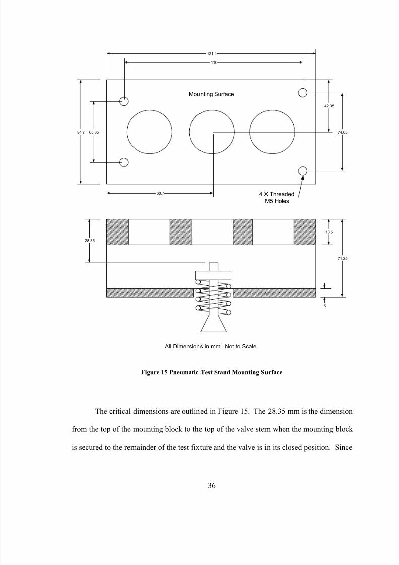
measurements taken from the mounting block, Figure 15 was developed.
35
8/14/2019 Camless Engine Thesis Final
http://slidepdf.com/reader/full/camless-engine-thesis-final 46/94
Mounting Surface
84.7 65.65
110
121.4
42.35
74.65
60.7 4 X Threaded
M5 Holes
All Dimensions in mm. Not to Scale.
28.35
13.5
71.25
5
Figure 15 Pneumatic Test Stand Mounting Surface
The critical dimensions are outlined in Figure 15. The 28.35 mm is the dimension
from the top of the mounting block to the top of the valve stem when the mounting block
is secured to the remainder of the test fixture and the valve is in its closed position. Since
36

8/14/2019 Camless Engine Thesis Final
http://slidepdf.com/reader/full/camless-engine-thesis-final 47/94
the piston makes direct contact with the top of the valve stem and the piston must
translate 10 mm, this 28.35 mm dimension dictates much of the dimensional layout of
both the cylinder block and the piston. Also of prime importance are the four bolt holes
and the bolt pattern. This pattern must be duplicated on the camless engine prototype to
enable assembly.
Since the test fixture’s dimensions need to match, an assembly concept was
produced to drive the detail dimensions of the piston, cylinder block and the bore plates
used to seal the cylinder block. This assembly schematic can be seen in Figure 16.
5 mm
Engine Valve Fully
Closed
O-ring
Counter Bore
for Button
Head Cap
Screws
Mounting
Block
Bore Plate
Cylinder BlockPiston
Figure 16 Cylinder Block Mounting Schematic
37

8/14/2019 Camless Engine Thesis Final
http://slidepdf.com/reader/full/camless-engine-thesis-final 48/94
The design shown schematically in Figure 16 demonstrates some key design
elements. First, button head cap screws will be used and mounted into a counter bore.
This is necessary to obtain a flush fit with the mounting block. Any other connection is
undesirable because only a face-to-face fit ensures that the valve stem will be a specific
distance from the centerline of the cylinder block.
Second, a seal is required to prevent pressurized hydraulic fluid from leaking past
the bore plate. This seal represents another problem because it must not only prevent
leakage, it must do so without introducing high levels of friction on the reciprocating
shaft.
Finally, an important dimension results from the assembly. Regardless of piston,
cylinder block, and bore plate design, the center line of the piston must offset 5 mm from
the centerline of the cylinder block when the engine valve is closed. This maintains
symmetry within the system and allows for the piston to translate 10 mm, 5 mm on either
side of center, and actuate the valve the required 10 mm.
With dimensional constraints beginning to emerge, other design parameters were
chosen arbitrarily as a starting point for detail development of the piston and bore. From
these originally chosen dimensions, equations were established to outline the relationship
between critical dimensions. Of greatest concern was the design of the piston and how its
dimensions affected the interface location of ports A and B with the bore. This critical
concern stems from the need to avoid hydraulic lock while maintaining the required 10
mm valve translation. The goal was to maintain full stroke without interfering with the
port/bore interface.
38

8/14/2019 Camless Engine Thesis Final
http://slidepdf.com/reader/full/camless-engine-thesis-final 49/94
To establish the location of ports A and B along the length of the bore, the
following simple equation was derived.
( ) DS P L ++⋅=21 Eq. 1
Where,
P ≡ Length of Piston
S ≡ Total Length of Valve Stroke Required
D ≡ Diameter of Port
L ≡ Minimum Length from Bore Center Line to Port Center Line
Piston
Bore Center
Line
Port
P S/2 D/2
L
Figure 17 Piston and Port Relationship
Based on the value of L, calculated above, and the given port configuration from
ISO 4401, the angle of the port A and B holes are defined as shown schematically in
Figure 14. Having defined the basic parameters of the ports based on arbitrary
dimensions, focus turned to the detail design of the piston.
39
8/14/2019 Camless Engine Thesis Final
http://slidepdf.com/reader/full/camless-engine-thesis-final 50/94
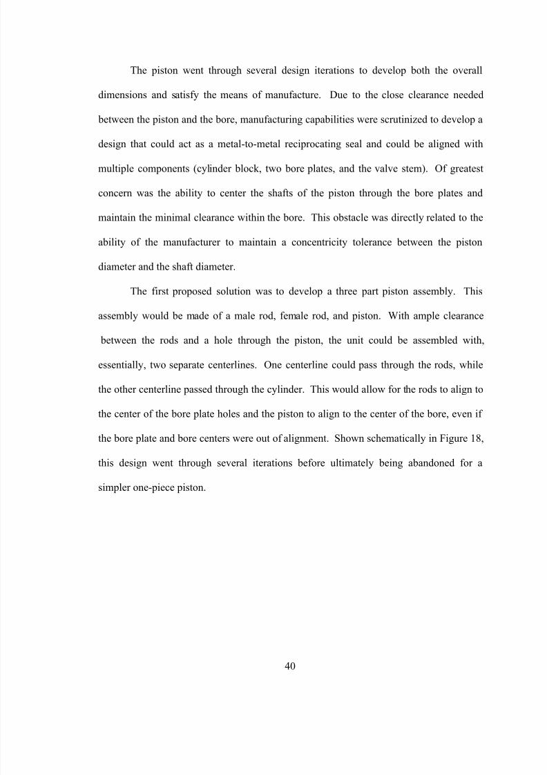
The piston went through several design iterations to develop both the overall
dimensions and satisfy the means of manufacture. Due to the close clearance needed
between the piston and the bore, manufacturing capabilities were scrutinized to develop a
design that could act as a metal-to-metal reciprocating seal and could be aligned with
multiple components (cylinder block, two bore plates, and the valve stem). Of greatest
concern was the ability to center the shafts of the piston through the bore plates and
maintain the minimal clearance within the bore. This obstacle was directly related to the
ability of the manufacturer to maintain a concentricity tolerance between the piston
diameter and the shaft diameter.
The first proposed solution was to develop a three part piston assembly. This
assembly would be made of a male rod, female rod, and piston. With ample clearance
between the rods and a hole through the piston, the unit could be assembled with,
essentially, two separate centerlines. One centerline could pass through the rods, while
the other centerline passed through the cylinder. This would allow for the rods to align to
the center of the bore plate holes and the piston to align to the center of the bore, even if
the bore plate and bore centers were out of alignment. Shown schematically in Figure 18,
this design went through several iterations before ultimately being abandoned for a
simpler one-piece piston.
40

8/14/2019 Camless Engine Thesis Final
http://slidepdf.com/reader/full/camless-engine-thesis-final 51/94
Piston
Piston
Male
Rod
Female
Rod
Male
Rod
Female
Rod
Threaded Three Piece Piston Concept
Assembled Three Piece
Piston Concept
Figure 18 Three Piece Piston Concept
It was decided with a high quality manufacturer, a one piece piston could be
developed that would have adequate geometric tolerances. Combining a well
manufactured one-piece piston with a position tolerant bore plate design would be
adequate. This change results in fewer components and a simpler design.
Similar to the three-piece piston design, the one-piece piston went through several
design iterations of both size and geometry. Following a consultation with the
manufacturing group at Siemens Diesel Systems Technology (DST), Blythewood, SC,
41

8/14/2019 Camless Engine Thesis Final
http://slidepdf.com/reader/full/camless-engine-thesis-final 52/94
the final piston design was completed. This design created the basis for the development
of the remaining components, including the bore plate and the cylinder block. Below are
some of the critical factors associated with the piston. See Figure 19.
• The piston diameter and tolerance shall be 15 mm.000.0
003.0000. +
−
• The bore diameter and tolerance shall be 15.003 ± 0.001 mm.
• Rough machining must leave approximately 0.03 mm for the grinding operation.
• Both ends of the rod shall be chamfered to allow for ease of manufacture and
maintenance of concentricity tolerance.
• An undercut is needed at the piston and rod interface to ease grinding.
Siemens DST indicated that post heat-treat grinding would clean-up any concentricity
problems. This realization made the one-piece piston design a feasible approach.
Grind Grind
10.000 ± .01 mm
9.5 to 9.8 ± .1 mm
Undercut Piston
Groove
Not to Scale
3-4 mm
60 or 90°
R 0.04 mm0.3 mm
15.000+0.000
-0.003
Figure 19 Piston Manufacturing Critical Concerns
42
8/14/2019 Camless Engine Thesis Final
http://slidepdf.com/reader/full/camless-engine-thesis-final 53/94
Based on these diameters, calculations were developed to understand the output
force of the unit based on the input pressure. The following example demonstrates the
force calculations for an input pressure of 50 bar. Conversions are included for ease of
understanding.
( )2
r r r A ⋅=π Area of the rod Eq. 2
( )2
p p r A ⋅=π Area of the piston Eq. 3
r p A A A −= Area of pressure contact Eq. 4
A P F ⋅= Force generated by pressure Eq. 5
For example, r r = 5 mm, r p = 7.5 mm, and P = 50 bar = 5 N/mm2. This results in a force
of 490.875 N or 110.4 lbf.
Based on equations 2 – 5, the force output can be calculated for any pressure
input. These equations can be used to determine the needed hydraulic pressure based on
the resistive forces of opening the engine valve.
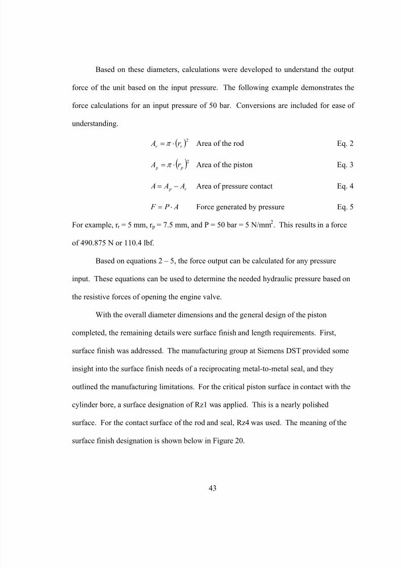
With the overall diameter dimensions and the general design of the piston
completed, the remaining details were surface finish and length requirements. First,
surface finish was addressed. The manufacturing group at Siemens DST provided some
insight into the surface finish needs of a reciprocating metal-to-metal seal, and they
outlined the manufacturing limitations. For the critical piston surface in contact with the
cylinder bore, a surface designation of Rz1 was applied. This is a nearly polished
surface. For the contact surface of the rod and seal, Rz4 was used. The meaning of the
surface finish designation is shown below in Figure 20.
43
8/14/2019 Camless Engine Thesis Final
http://slidepdf.com/reader/full/camless-engine-thesis-final 54/94
Nominal Surface
Surface Roughness
1 µm
1 µm
Rz1 Designates ± 1 micron high defect
from the nominal surface.
Figure 20 Surface Roughness Example
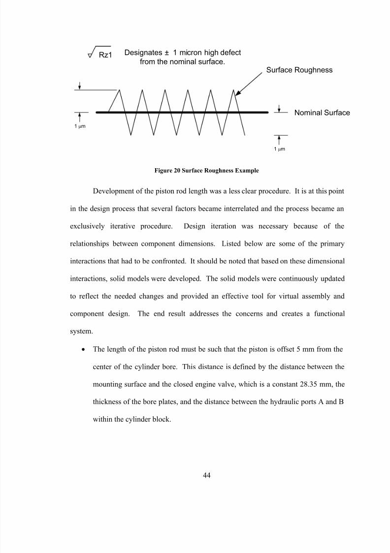
Development of the piston rod length was a less clear procedure. It is at this point
in the design process that several factors became interrelated and the process became an
exclusively iterative procedure. Design iteration was necessary because of the
relationships between component dimensions. Listed below are some of the primary
interactions that had to be confronted. It should be noted that based on these dimensional
interactions, solid models were developed. The solid models were continuously updated
to reflect the needed changes and provided an effective tool for virtual assembly and
component design. The end result addresses the concerns and creates a functional
system.
• The length of the piston rod must be such that the piston is offset 5 mm from the
center of the cylinder bore. This distance is defined by the distance between the
mounting surface and the closed engine valve, which is a constant 28.35 mm, the
thickness of the bore plates, and the distance between the hydraulic ports A and B
within the cylinder block.
44

8/14/2019 Camless Engine Thesis Final
http://slidepdf.com/reader/full/camless-engine-thesis-final 55/94
• The distance that the ports are separated is based on several parameters. Of
primary concern is the requirement that the piston must actuate a minimum of 10
mm without covering the hydraulic ports. Second, they must be as close together
as possible to minimize the fluid volume within the bore.
• The bore must be physically separated from any other machining operations to
avoid distortion. The result of this can be seen as the bore being offset from the
threaded connections needed to assemble to the spool valve.
• The piston, itself, must be of reasonable length so that it maintains its orientation
while translating. A piston that is too short has a greater chance of tilting slightly
and becoming jammed within the cylinder bore.
• The piston surface area in contact with the cylinder bore should be small to reduce
the friction between surfaces.
The results of this design process are shown schematically below in Figure 21.
As shown in Figure 21, some of the components appear oversized. However, this
assembly looks odd only because of the mating requirements to the other components.
45

8/14/2019 Camless Engine Thesis Final
http://slidepdf.com/reader/full/camless-engine-thesis-final 56/94
Bore PlateBore Plate
Cylinder Block
Piston
A B
Figure 21 Final Piston – Cylinder Concept
Sealing was the final design aspect to be addressed following the iterative process
needed to produce the components shown in Figure 21. It was already decided that o-
rings on any of the reciprocating components may introduce too much friction and be
detrimental to the design. Therefore, polytetrafluoro-ethylene (PTFE) lip seals were
located and integrated into the design of the bore plates.
The lip seals used are a stock item from Fluorocarbon Company Limited,
Hertford Herts, England, UK. Therefore, there is a manufacturer recommended design
for the gland that was utilized. The manufacturer gland design was added to the bore
46

8/14/2019 Camless Engine Thesis Final
http://slidepdf.com/reader/full/camless-engine-thesis-final 57/94
plate drawings. This seal would prevent hydraulic fluid leaking past the reciprocating
interface between the piston rod and the bore plates.
A second static seal was required to prevent leakage from between the bore plates
and the cylinder block. This seal was accomplished through the use of an o-ring, and
again, its gland dimensions were based on the manufacturer’s recommendation.
Finally sealing between the spool valve and the cylinder block was considered.
Fortunately, the spool valve has the static o-ring glands integral to its design. Therefore,
the design of the cylinder block only needed to have the hydraulic port holes smaller in
diameter than the o-rings to affect a good seal.
With the sealing concerns addressed, and the detail drawings completed, the
project’s focus turned to the manufacture of the components.
47

8/14/2019 Camless Engine Thesis Final
http://slidepdf.com/reader/full/camless-engine-thesis-final 58/94
3.2 Manufacturing
Due to the tight tolerances of the machining, the project team turned to Siemens
DST for manufacturer recommendations. They provided the following list of contacts
and stated that considering the microns clearance between the piston and the bore, a
limited number of facilities could complete the project.
• C & A Tool, Churubusco, IN; contact Todd Rehrer (219) 693-2167
• Alpha Manufacturing, West Columbia, SC; contact Charlie Hicks (803) 739-4500
• Chucking Machine, Chicago, IL; contact Tim Merrigan (847) 678-1192
Each of the manufacturers were sent a request for quote package that included
drawings of the three components and an assembly schematic, the requested lead time,
heat treat requirements, and the total number of parts. For this phase, the project team
requested three complete prototype units. This includes three cylinder blocks, three
pistons, and six bore plates. The request for three was justified by three parameters.
First, there was little cost increase between the production of one and that of three, and
second, by obtaining three sets, it was more likely that a good working unit would be
available. Finally, there was a concern that the learning process associated with the
control of the piston translation may lead to damaged components.
Through the quoting process, Alpha Manufacturing had the best combination of
price, manufacturing capability, and lead time. Therefore manufacturing of the
components began at Alpha Manufacturing in December, 2000.
48

8/14/2019 Camless Engine Thesis Final
http://slidepdf.com/reader/full/camless-engine-thesis-final 59/94
Due to the tolerances and clearances associated with the piston and cylinder bore,
Alpha chose to match-grind components. This resulted in specific pistons that were
matched to specific cylinder blocks. The bore plates had less critical dimensions and
were interchangeable among the assemblies.
Components were completed in stages, but the first complete assembly was ready
in late January, 2001. Upon its receipt, assembly procedures began.
49

8/14/2019 Camless Engine Thesis Final
http://slidepdf.com/reader/full/camless-engine-thesis-final 60/94
3.3 Assembly
3.3.1 Assembly of the Camless Engine Actuator
The major components that make-up the camless engine actuator are two bore
plates, one cylinder block, one piston, and the piezoelectric controlled spool valve.
Additional elements include the fasteners, o-rings, and PTFE lip seals.
Assembly went very smoothly aside from the insertion of the lip seals. Because
of their small diameter, they were very difficult to install. The manufacturer was
questioned, and they confirmed that the gland design was correct. Furthermore, they
provided some suggestions for installing the seals. Normally lip seals of this design are
to be installed by placing part of the seal into the gland and working the remaining
diameter into the assembly by symmetrically pressing with ones thumbs. With the small
diameter this was impossible. Instead, the entire unit was deformed simultaneously and
pressed into the gland. This was accomplished by two different methods. The first used
a piston from the camless engine assembly to support the inside diameter of the seal and
force the seal into the gland. Using the piston was abandoned for fear of damaging the
unit; instead, the seals were forced by pressing the entire unit with one’s thumb into the
gland. After one failed attempt, this process proved to be very successful.
The result of the camless engine actuator assembly is shown below in Figure 22.
This assembly was then connected to the pneumatic test stand via the mounting plate
shown in Figure 15.
50

8/14/2019 Camless Engine Thesis Final
http://slidepdf.com/reader/full/camless-engine-thesis-final 61/94
Bore Plates Cylinder
Block
Piston
Mounting Block
Engine Valve
Lip seal
Lip seal
Figure 22 Hydraulic Actuator and Mounting Block Assembly
51

8/14/2019 Camless Engine Thesis Final
http://slidepdf.com/reader/full/camless-engine-thesis-final 62/94
Figure 22 shows a cutaway view of the camless engine actuator assembly.
Because it is cutaway, the spool valve and the ISO 4401 port connections are not visible.
In this view, the spool valve would be coming out of the paper toward the reader. A
schematic of the assembly from the side can be seen later in Figure 27.
The camless engine actuator assembly and mounting block were then attached to
the hydraulic test bench. Hydraulic connections and layout are addressed in the next
section.
52

8/14/2019 Camless Engine Thesis Final
http://slidepdf.com/reader/full/camless-engine-thesis-final 63/94
3.3.2 Assembly of the Hydraulic System
The camless engine actuator assembly outlined in the previous section was
mounted onto the hydraulic test stand. Hydraulic connections were made via the standard
hydraulic threaded connection ¼ - 19 BSP (British Straight Pipe). The system flows
hydraulic fluid from a pump and back to a reservoir and is a self contained scheme.
Hydraulic fluid is pumped through a ball valve and into the side port of the
cylinder block. This connection is directly routed to the P port of the spool valve. From
there, the position of the spool valve determines where the pressurized fluid goes. In the
neutral position, the fluid is dead-headed, and aside from any leakage past the spool, the
fluid is static. See Figure 23.
53

8/14/2019 Camless Engine Thesis Final
http://slidepdf.com/reader/full/camless-engine-thesis-final 64/94
Spool
Valve
Piston
Drain
Supply Pressure
Drain
Figure 23 Hydraulic Amplifier Schematic
When the spool valve translates up, fluid flows through the B port and pressurizes
the upper cavity of the cylinder block. This pressurization results in the downward
translation of the piston. In turn, the engine valve is being opened as the piston translates
down. This is shown in Figure 24.
54

8/14/2019 Camless Engine Thesis Final
http://slidepdf.com/reader/full/camless-engine-thesis-final 65/94
Large
DisplacementDown
Drain
Supply
B Port
A PortDrain
Small
Displacement
Up
Figure 24 Hydraulic Amplifier – Spool Valve Up
The opposite occurs as the spool valve translates down. Fluid flows through the
A port and pressurizes the lower cavity of the cylinder block. This pressure causes the
piston to rise and allows the engine valve to close. See Figure 25.
55

8/14/2019 Camless Engine Thesis Final
http://slidepdf.com/reader/full/camless-engine-thesis-final 66/94
Large
Displacement
Up
Drain
Supply
B Port
A Port
Drain
Small
Displacement
Down
Figure 25 Hydraulic Amplifier – Spool Valve Down
Drainage of fluid from the cylinder block takes place through the A or B port,
whichever is not being pressurized by the spool valve. As the piston translates toward the
non-pressurized port, hydraulic fluid is forced back into the spool valve. This fluid is
then routed directly to the T port (drain) and returns to the reservoir. From the reservoir,
the fluid is pumped back into the system, and the process repeats.
56

8/14/2019 Camless Engine Thesis Final
http://slidepdf.com/reader/full/camless-engine-thesis-final 67/94
In addition to the test rig described above, a second pump can be added in parallel
to meet the demands of increased hydraulic flow. This additional hydraulic line has its
own isolation ball valve. It is piped in parallel to the primary pump and joins the system
just prior to the fluid connection into the supply side of the cylinder block, connected to
port P (supply).
The hydraulic flow described above is based on the control signal generated by
the electronics and supplied to the piezoelectric stacks. The development of the control
system is discussed in the following section.
57

8/14/2019 Camless Engine Thesis Final
http://slidepdf.com/reader/full/camless-engine-thesis-final 68/94
3.3.3 Assembly of the Control System
The control of the camless engine system is facilitated by a series of electrical
components that ultimately supply a variable voltage to piezoelectric stacks. The applied
voltage causes expansion of the stacks, and in-turn causes the displacement of the
hydraulic spool valve.
Considerable time was spent troubleshooting and gaining an understanding of the
high voltage (HV) amplifier 1
for the piezoelectric device. During initial trials, there was
no observable voltage output from the amplifier, and the piezoelectric stacks would not
respond. Upon disassembly it was observed that some of the electronics had broken free
of their adhered connections and had fallen against other components. This caused a
short and promptly blew a fuse. After repairing the unit and replacing the fuse, the HV
amplifier provided an output to the piezoelectric stacks.
A second problem was observed with the HV amplifier box. Although an output
voltage could be measured, it did not have the power needed to provide movement to the
piezoelectric stacks. During troubleshooting, the output of the AC to DC converter 2
within the HV amplifier box was found to be outputting 15 volts. This was low
compared to the expected 24 V needed to supply the amplifier. Without the 24 V feeding
the voltage splitter and amplifier, there was not enough power to actuate the stacks.
Following more investigation, a clue was found printed on the AC to DC
converter. It read that the expected input was 240 V AC for an output of 24 V DC. After
58

8/14/2019 Camless Engine Thesis Final
http://slidepdf.com/reader/full/camless-engine-thesis-final 69/94
some rewiring, a nominal 220 V AC was supplied to the unit. The actual output of the
220 V outlet was very high and averaged 250 volts. The input of 250 V resulted in an
output of 32 V from the AC to DC converter. This combined with testing at a nominal
110 V input , actually 120 V, and an output of 15 V revealed a constant AC to DC
conversion factor. This conversion factor was approximately 1 V DC output to 8 V AC
input. Based on this conversion, the required input of 192 V AC should provide 24 V DC
output. This was later found to be correct after more wiring changes.
The input requirements of the HV amplifier box was the key element to getting
the controls to operate. Originally, the project team was told that the box could operate at
both 110 or 220 V input. This was found to be incorrect. The set-up shown in Figure 26
demonstrates the wiring series used to obtain the 24 V DC from the AC to DC converter.
59

8/14/2019 Camless Engine Thesis Final
http://slidepdf.com/reader/full/camless-engine-thesis-final 70/94
AC to DC
Converter 110 V
Nominal
122 V AC
Variable
Transformer
Set at 92 V
Step-up
Transformer
92 V AC 192 V AC
AC to DC
Converter
HV
Amplifier
24 V DC
0 - 200 V
DC
200 - 0 VDC
Piezoelectric
Stacks
Function
Generator
± 10 V DC Max.
Variable Voltage
Input
Figure 26 Wiring Schematic
More rewiring was required to supply the needed power to both the controls and the
pump simultaneously. This involved making changes from the German (Shuko) plug to
an American configuration. Once the rewiring was complete, the entire system was
operational. The final form of the test rig wiring is as follows.
60

8/14/2019 Camless Engine Thesis Final
http://slidepdf.com/reader/full/camless-engine-thesis-final 71/94
• Hydraulics: The pump is wired directly into a 3-pole locking 220 V outlet.
• Electronics: The electronic wiring advances from an outlet at 122 V AC to a
variable output transformer to create 92 V AC. This 92 V AC is doubled plus a
small offset through a step-up transformer. The resulting 192 V AC supplies the
AC to DC converter in the HV amplifier box. The converter supplies 24 V DC to
the splitter/amplifier.
The splitter/amplifier outputs two voltage signals based on a separate input
voltage wave. One output signal is 0 – 200 V DC and the other is 200 – 0 V DC.
For example, both signals can be at 100 V DC simultaneously, but for one signal
at 50 V DC, the other is at 150 V DC. Furthermore, the extreme occurs when one
signal is 0 V DC and the other is 200 V DC. These two variable DC signals are
based on a separate voltage input supplied by a function generator. The nominal
input from the function generator to create the full range 0 – 200 V DC is ± 10 V
DC with a 0 V DC offset at variable frequencies.
1 Produced by Marco, Hermsdorf, Germany2 Produced by Hydraulik Ring, Nűrtingen, Germany
61
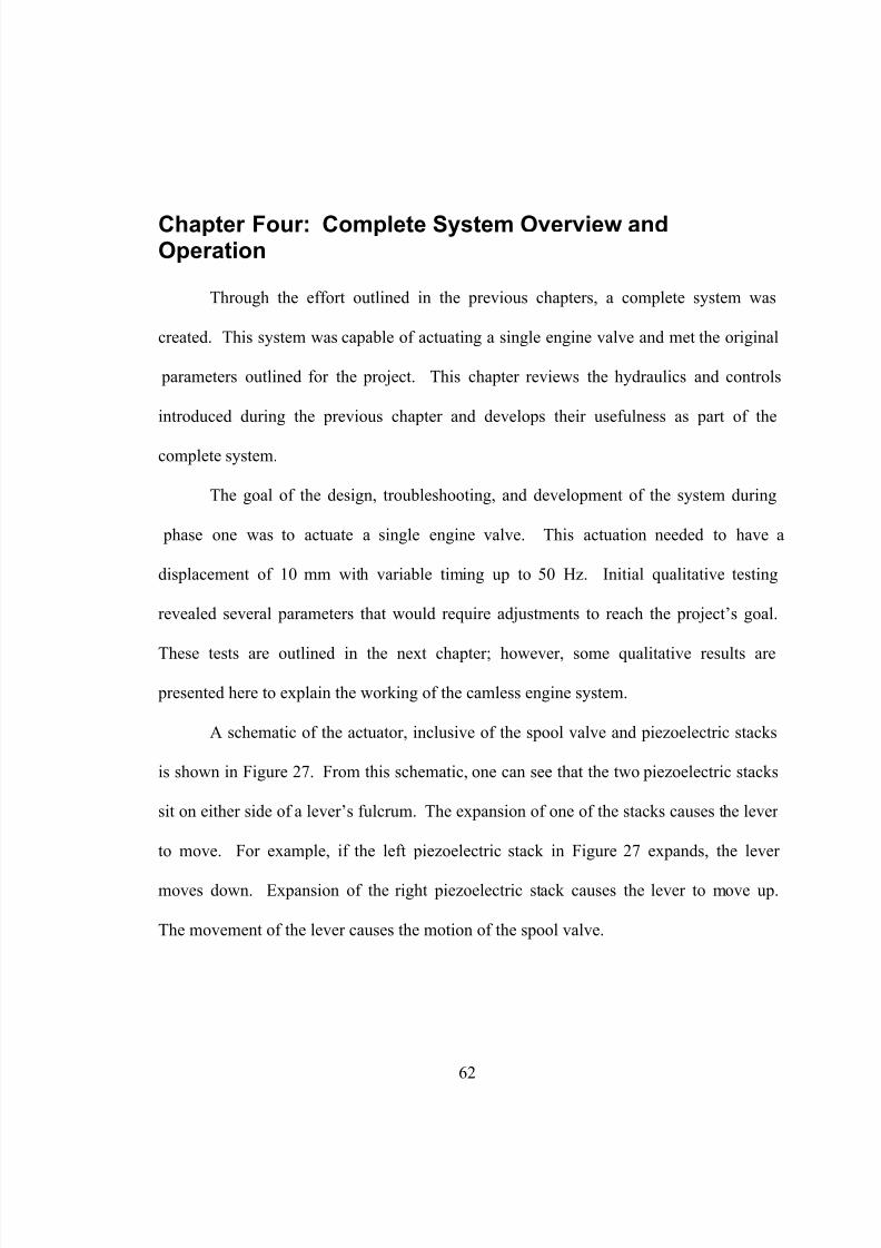
8/14/2019 Camless Engine Thesis Final
http://slidepdf.com/reader/full/camless-engine-thesis-final 72/94
Chapter Four: Complete System Overview andOperation
Through the effort outlined in the previous chapters, a complete system was
created. This system was capable of actuating a single engine valve and met the original
parameters outlined for the project. This chapter reviews the hydraulics and controls
introduced during the previous chapter and develops their usefulness as part of the
complete system.
The goal of the design, troubleshooting, and development of the system during
phase one was to actuate a single engine valve. This actuation needed to have a
displacement of 10 mm with variable timing up to 50 Hz. Initial qualitative testing
revealed several parameters that would require adjustments to reach the project’s goal.
These tests are outlined in the next chapter; however, some qualitative results are
presented here to explain the working of the camless engine system.
A schematic of the actuator, inclusive of the spool valve and piezoelectric stacks
is shown in Figure 27. From this schematic, one can see that the two piezoelectric stacks
sit on either side of a lever’s fulcrum. The expansion of one of the stacks causes the lever
to move. For example, if the left piezoelectric stack in Figure 27 expands, the lever
moves down. Expansion of the right piezoelectric stack causes the lever to move up.
The movement of the lever causes the motion of the spool valve.
62

8/14/2019 Camless Engine Thesis Final
http://slidepdf.com/reader/full/camless-engine-thesis-final 73/94
Piezoelectric StacksSolid Hinge and
Lever
Spool Valve
Piston
Engine Valve
Figure 27 Complete System Schematic
63

8/14/2019 Camless Engine Thesis Final
http://slidepdf.com/reader/full/camless-engine-thesis-final 74/94
The expansion of the piezoelectric stacks is generated by the input voltage from
the HV amplifier Box. As discussed in the previous section, there are two input signals.
One input ranges from 0 – 200 V DC, while the other is exactly opposite ranging from
200 – 0 V DC. One signal powers one stack, while the other powers the other stack.
Using this arrangement, the two stacks never expand at the same time. The cycling of
expansion from one stack to the other allows the lever to oscillate up and down, and
therefore, oscillates the spool valve.
The oscillation of the spool valve directs the hydraulic flow path. Based on the
spool’s position, the fluid can either divert to the top of the adjacent piston or the bottom.
This pressurization causes the piston to displace down or up, respectively. Since the
piston is in direct contact with the engine valve, its movement is equal to the
displacement of the engine valve.
Early qualitative tests showed the engine valve displaced 11 mm with 50 bar input
pressure and low frequencies ( ≤ 15 Hz ). This early testing was not designed to provide
detailed data; instead, it was part of the discovery process. Adjustments to input
pressure, frequency and nominal spool valve position were continuously done until the
unit was functioning well. It should be noted that during these early tests, the input
voltage frequencies were limited to a simple sine wave with amplitudes varying from 1 to
10 V.
During the qualitative testing and system set-up, it was also observed that the
engine valve displacement and/or stroke became smaller with increasing frequency. This
led to questions about flow rate limitations. To check whether the limitations were due to
the available hydraulic fluid, the input flow rate was doubled by bringing the second
64

8/14/2019 Camless Engine Thesis Final
http://slidepdf.com/reader/full/camless-engine-thesis-final 75/94
pump on-line. The added fluid was mixed into the flow prior to entering the cylinder
block.
This additional fluid flow did not alter the engine valve displacement; therefore, it
was concluded that the available input flow rate was sufficient. The next logical step was
to observe the flow rate through the system. It was here, that formal testing began. The
testing is outlined in the following chapter.
65

8/14/2019 Camless Engine Thesis Final
http://slidepdf.com/reader/full/camless-engine-thesis-final 76/94
Chapter Five: System Testing
5.1 Flow Rate Experiments
Flow rate testing can be divided into multiple phases. For all testing, the
experiments were divided into three distinct runs – both pumps, right pump only, and left
pump only. Since the pumps themselves are together, the distinction of left and right is
based on the location of their isolation ball valve.
Initially, flow rate testing was done to determine the flow output of the pump
systems. These measurements were necessary to ascertain the maximum flow rate
available to the camless engine system. For these measurements, flow was diverted from
the camless system, just prior to its entrance into the cylinder block, into a graduated
cylinder. Practice runs were made to determine the length of time to use for each run
without overflowing the graduated cylinder. When running both pumps, a time limit of 5
seconds was used for each test. The tests were repeated a minimum of five times to
establish consistency in volumetric readings. These readings were established for a
variety of pressures. Pump pressures were set with the isolation valves closed.
The following graph (Figure 28) shows the output volumetric flow rate for a
variety of input pressures. Except at pressures below 20 bar where the readings became
unstable and inconsistent, the available flow rate is relatively constant regardless of input
pressure. This is reasonable considering the input pressure could only be established in a
static situation, but pumping into the graduated cylinder creates nearly zero pressure
66
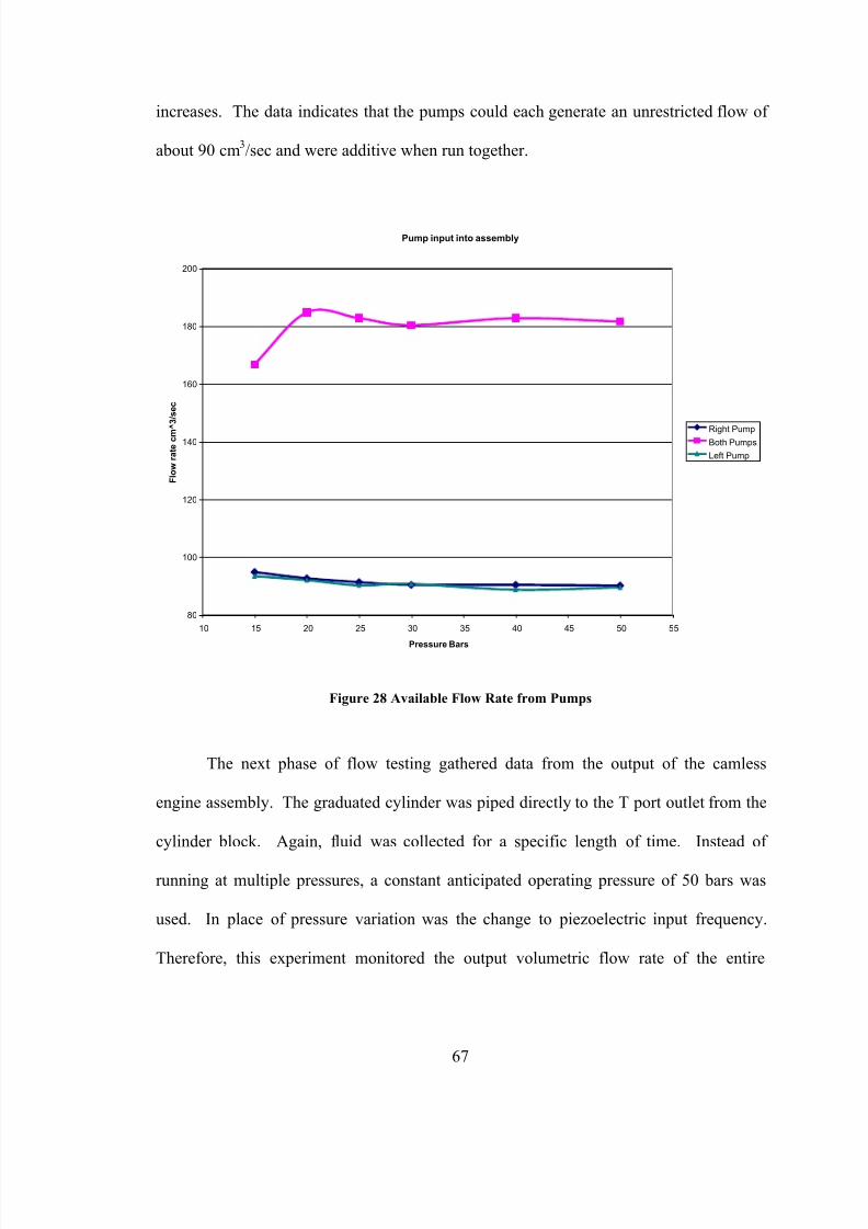
8/14/2019 Camless Engine Thesis Final
http://slidepdf.com/reader/full/camless-engine-thesis-final 77/94

8/14/2019 Camless Engine Thesis Final
http://slidepdf.com/reader/full/camless-engine-thesis-final 78/94
assembly compared to the input frequency of the spool valve control. These results are
shown in Figure 29.
CLE Output Volumetric Flow Rate
20
22
24
26
28
30
32
0 10 20 30 40 50 60
Frequency (Hz)
F l o w
r a t e ( c m ^ 3 / s )
P = 50 bar
Figure 29 Camless Engine Return Flow Rate
Fluid returning to the reservoir does so at approximately 28 cm3/sec for input
frequencies within the anticipated operating range – those between 15 and 50 Hz.
Considering this value, flow rate is obviously restricted by the assembly. This restriction
in flow rate is hypothesized to be the reason for reduced engine valve displacement at
higher frequencies. This return volumetric flow rate is approximately 1/3 of the available
flow rate provided by one pump.
Based upon the findings in the output flow rate experiment, an examination into
the volumetric requirements of actuating the engine valve ensued. The design of the
68

8/14/2019 Camless Engine Thesis Final
http://slidepdf.com/reader/full/camless-engine-thesis-final 79/94
cylinder block and piston, combined with the design requirement for valve stroke results
in a constant fluid volume requirement. The pressure contact area found in Eq. 4
multiplied by the required stroke of 10 mm results in a volume of 982 mm3
or 0.982 cm3.
This volume is equal to the volume of fluid required to actuate the engine valve 10 mm in
one direction. Twice this volume is required to complete one cycle of both opening and
closing the engine valve. Therefore, 1.964 cm3
must be supplied and evacuated from the
assembly during each stroke or period. From this requirement of 1.964 cm3, volumetric
flow rate requirements can be extrapolated for all anticipated frequencies. These data are
shown graphically in Figure 30.
Volumetric Flow Rate Requirement based on Engine Valve Frequency
0
10
20
30
40
50
60
70
80
90
100
110
0 10 20 30 40 50 60
Frequency (Hz)
V o l . F l o w
r a t e ( c m ^ 3 / s )
50 Bar
Figure 30 Theoretical Flow Rate Requirements vs. Input Frequency
69

8/14/2019 Camless Engine Thesis Final
http://slidepdf.com/reader/full/camless-engine-thesis-final 80/94
Considering that the output flow rate through the CLE system was found to be 28
cm3/sec, the theoretical maximum frequency that the engine valve can obtain full
displacement is approximately 15 Hz. For frequencies greater than 15 Hz, the engine
valve displacement would reduce. This is due to the conflict between constant flow rate
input and higher volumetric flow rate demands due to increased cycles per second.
To verify the theoretical results discussed above, displacement testing was
performed on the engine valve. These tests and their results are outlined in the next
section.
70

8/14/2019 Camless Engine Thesis Final
http://slidepdf.com/reader/full/camless-engine-thesis-final 81/94
5.2 Valve Displacement Testing
Displacement testing was designed to monitor the position and the extremes of
engine valve movement. For these experiments, an LVDT was attached to the CLE
piston. Output values from the LVDT in the form of voltages were monitored using an
oscilloscope. The following results were based on monitoring the oscilloscope’s output
and determining the voltage for both the extreme open and extreme closed position of the
engine valve. The voltages were then converted into position measurements based on the
voltage vs. displacement calibration curve. From this data, the distance the valve opened
and the distance the valve remained open when it was to be closed was determined.
Furthermore, the difference of the two positions equals the valve stroke. The results of
the 50 Bar test are shown in Figures 31 and 32.
71

8/14/2019 Camless Engine Thesis Final
http://slidepdf.com/reader/full/camless-engine-thesis-final 82/94
Valve Displacement vs. Frequency (50 Bar)
-2
0
2
4
6
8
10
12
0 10 20 30 40 50 60
Frequency (Hz)
D i s t a n c e O p e n ( m m )
Valve Closed
Valve Open
Figure 31 Valve Displacement vs. Input Frequency
72

8/14/2019 Camless Engine Thesis Final
http://slidepdf.com/reader/full/camless-engine-thesis-final 83/94
Valve Stroke vs. Frequency (50 Bar)
0
2
4
6
8
10
12
0 10 20 30 40 50 60
Frequency (Hz)
V a l v e S t r o k e ( m m )
Stroke
Figure 32 Valve Stroke vs. Input Frequency
Shown in Figure 31, the amount that the valve is open, when it is supposed to be
open, decreases steadily with increasing frequencies above 14 Hz. The valve begins to
remain open, when it is supposed to be shut, for frequencies above 15 Hz. The amount
that the valve remains open also steadily increases with increasing frequency. The results
of the changes in displacement for both the open and closed valve position can be seen in
Figure 32. This shows that the valve stroke begins to decrease steadily for frequencies
greater than 15 Hz.
This experiment supports the calculated maximum frequency for maximum valve
stroke. Furthermore, the valve stroke decreases at a nearly linear rate between 15 and 50
Hz. This is also in support of the calculations showing that the volumetric fluid flow
73

8/14/2019 Camless Engine Thesis Final
http://slidepdf.com/reader/full/camless-engine-thesis-final 84/94
remains constant, but as the number of strokes/sec increase (i.e. frequency), the
compensation for limited flow is reduced valve displacement.
It should be noted that all the previously discussed testing was done with a
sinusoidal voltage input at ± 10 V DC with a 0 V DC offset. Other qualitative testing has
demonstrated that changing from a sinusoidal wave to a square wave input dramatically
affects the overall operation of the system.
74

8/14/2019 Camless Engine Thesis Final
http://slidepdf.com/reader/full/camless-engine-thesis-final 85/94

8/14/2019 Camless Engine Thesis Final
http://slidepdf.com/reader/full/camless-engine-thesis-final 86/94
While monitoring the LVDT signal with the oscilloscope, the threaded rod
controlling the position of the spool was manipulated. This process continued until the
time fully closed and fully open became equal. The locknut was then tightened to secure
the position of the spool. Immediately, the entire prototype showed considerable
improvement.
Flow testing was repeated for the output flow rate of the system. These tests
indicated a significant increase of volumetric flow rate. The output flow varied between
70 to 85 cm
3
/sec based on the operating temperature of the hydraulic fluid.
At low operating temperatures, the displacement testing was repeated. This
testing resulted in full valve displacement at 36 Hz using a sine wave input at ± 10 V DC.
This value compares very favorably against the earlier results of 14 to 15 Hz.
Furthermore, the values of 70 cm3/sec and 36 Hz continue to prove the relationship
between output flow rate and theoretical maximum full displacement frequency.
Based on the favorable results from the sine wave input, tests were repeated using
a square wave input at ± 10 V DC. This voltage input results in full engine valve
displacement through the entire 1 to 50 Hz operating range.
It was also observed that at low frequencies, lower voltage inputs continued to
produce full engine valve displacement. These recent finding indicate the system is
operating at greater capacity and upholds the theory that custom voltage inputs may
create even greater benefits.
76

8/14/2019 Camless Engine Thesis Final
http://slidepdf.com/reader/full/camless-engine-thesis-final 87/94
5.4 Qualitative Testing and System Observations
As mentioned in the preceding sections, other tests were conducted to observe the
response of the system. From these qualitative experiments, some thoughts have been
given to future experimentation to quantify these anomalies.
Of greatest interest is the system’s response to a change of waveform input to the
piezoelectric stacks. Sinusoidal experiments are well documented and outlined in the
previous sections; however, the introduction of a square wave input radically changes the
system. The square wave applies +10 V or – 10 V suddenly.
This sudden, binary application of voltage causes the spool valve to operate
similarly to a solenoid-based system. The result on the system is an increase in
displacement all the way to the piston’s physical stops. These stops are positioned to
prevent the piston from stroking more than 12 mm; therefore, the valve is stroking 12
mm. This impact with the physical stop can be heard, and its noise is similar to other
solenoid based camless engine attempts.
The ability to hear the impact and resolve that the valve is stroking 12 mm allows
for some audible observation. The noise of impact continues through the entire
frequency range from 1 to 50 Hz.
Based on the audible observations, it reasons that the input voltage waveform to
the piezoelectric stacks alters the flow characteristics of the system. This is reasonable,
considering the input voltage directly affects the positioning of the spool valve.
77

8/14/2019 Camless Engine Thesis Final
http://slidepdf.com/reader/full/camless-engine-thesis-final 88/94
Therefore, it reasons that the design of a custom waveform will allow for the quiet
control associated with the sinusoidal input, while generating the full valve stroke over a
greater range of frequencies.
78

8/14/2019 Camless Engine Thesis Final
http://slidepdf.com/reader/full/camless-engine-thesis-final 89/94
Chapter Six: Discussion
This development has proven the concept of replacing an internal combustion
engine’s camshaft with a piezoelectric controlled, hydraulic actuator. Valve stroke
requirements have been achieved, and, at some input variations, have been exceeded.
The actuator has also performed at frequencies well in excess of 50 Hz. Testing has
shown some limitations related to the flow rate and input waveforms. However, it is
these limitations that have provided the inspiration for continued development and
discovery.
Progress on the camless engine can continue into a second phase by investigating
the following. First, a detailed look at the voltage input waveform’s effect on the
operation of the system is in order. From this investigation, a new custom waveform can
be designed and generated by the existing equipment.
The two extremes of the waveforms have been already tested; namely the sine
wave and the square wave. Each provide some beneficial operating parameters.
Therefore, it is conceivable that the combination of the two will result in a beneficial
blend of their advantages.
A second design phase may also include a new approach to the overall system.
Of prime concern is the reduction of size. Thought has already been given to creating
smaller components and utilizing the developing piezoelectric technology under the
79

8/14/2019 Camless Engine Thesis Final
http://slidepdf.com/reader/full/camless-engine-thesis-final 90/94
“Thunder” model name. The initial concept is to sandwich a spool between two Thunder
piezoelectric devices and integrate the hydraulic amplifier into the engine valve.
Of course, an obvious future step is to incorporate the piezoelectric/hydraulic
system into a working engine. This will take the project far beyond its initial scope, as
the analysis can shift to examining the impact of a camless valvetrain on an operating
engine.
Regardless of the direction that the project takes, this phase can be considered
successful. The working unit proves that camless engines based on piezoelectric control
are feasible. This phase alone makes a broad leap into the automotive and actuator
technology of the future. It stands apart from previous attempts and has shown a new
way forward.
80

8/14/2019 Camless Engine Thesis Final
http://slidepdf.com/reader/full/camless-engine-thesis-final 91/94
Appendix
81

8/14/2019 Camless Engine Thesis Final
http://slidepdf.com/reader/full/camless-engine-thesis-final 92/94
References
Anderson, M; Tsao, T-C; and Levin, M., 1998, “Adaptive Lift Control for a Camless
Electrohydraulic Valvetrain,” SAE Paper No. 981029
Anonymous, “First Camless Truck Reaches the Summit of Pikes Peak!” Power
Stroke Registry, Spring 2001
Ashhab, M-S; and Stefanopoulou, A., 2000, “Control of a Camless Intake Process –
Part II,” ASME Journal of Dynamic Systems, Measurement, and Control – March
2000
Ashhab, M-S; and Stefanopoulou, A., 2000, “Control-Oriented Model for Camless
Intake Process – Part 1,” Transactions of the ASME Vol 122, March 2000
Dopson, et al “Lotus Variable Valve Train Systems for Production and
Development.”
Dobson, N. and Muddell, G., 1993, “Active Valve Train System Promises to
Eliminate Camshafts,” Automotive Engineer February/March 1993.
82

8/14/2019 Camless Engine Thesis Final
http://slidepdf.com/reader/full/camless-engine-thesis-final 93/94
General Motors – GM and the Environment. May 21, 2001. General Motors. June
13, 2001
<http://www.gm.com/company/gmability/environment/gm_and_the_env/releases/dis
placement_052101.htm>.
Gould, L; Richeson, W; and Erickson, F., 1991, “Performance Evaluation of a
Camless Engine Using Valve Actuation with Programmable Timing,” SAE Paper No.
910450.
Kim, D; Anderson, M; Tsao, T-C; and Levin, M., 1997, “Dynamic Model of a
Springless Electrohydraulic Valvetrain,” SAE Paper No. 970248
Ladd, D; Camless Engine is Gaining Momentum. September 13, 1999. Siemens
Automotive. July 4, 2000
<http://media.siemensauto.com/mediacenter2/queries/releasefull.phtml?prjob_num=1
195>.
Lamm, J.; “V-8-6-4, Cadillac Tries Multi Displacement” Road & Track November,
1980
Lexus – Variable Valve Timing a First in an SUV. Autoworld. June 18, 2001
<http://www.autoworld.com/RX300.htm>.
83

8/14/2019 Camless Engine Thesis Final
http://slidepdf.com/reader/full/camless-engine-thesis-final 94/94
Mori, Kaz. Honda’s High-Output LEV Engine Home Page. Honda. June 13, 2001
<http://s2000.vtec.net/jdmhtml/high-output-lev.htm>.
Murray, C; Electronic Controls to Replace Camshafts in Diesel Engines. April 14,
2000. EETimes.com. July 7, 2000
http://www.eetimes.com/story/industry/system_and_software_news/OEG20000414S
0050.htm>.
Richman et al “A Computer-Controlled Poppet-Valve Actuation System for
Application on Research Engines.”
Schechter, M.; and Levin, M., 1998, “Camless Engine,” SAE Paper No. 960581