cambium ptp 820g installation guide - doubleradius 001v000 accuracy while reasonable efforts have...
TRANSCRIPT

Cambium
PTP 820G
Installation Guide
System Release 7.9
phn-3967 001v000

phn-3967 001v000
Accuracy
While reasonable efforts have been made to assure the accuracy of this document, Cambium Networks
assumes no liability resulting from any inaccuracies or omissions in this document, or from use of the
information obtained herein. Cambium reserves the right to make changes to any products described
herein to improve reliability, function, or design, and reserves the right to revise this document and to
make changes from time to time in content hereof with no obligation to notify any person of revisions
or changes. Cambium does not assume any liability arising out of the application or use of any
product, software, or circuit described herein; neither does it convey license under its patent rights or
the rights of others. It is possible that this publication may contain references to, or information about
Cambium products (machines and programs), programming, or services that are not announced in
your country. Such references or information must not be construed to mean that Cambium intends to
announce such Cambium products, programming, or services in your country.
Copyrights
This document, Cambium products, and 3rd Party software products described in this document may
include or describe copyrighted Cambium and other 3rd Party supplied computer programs stored in
semiconductor memories or other media. Laws in the United States and other countries preserve for
Cambium, its licensors, and other 3rd Party supplied software certain exclusive rights for copyrighted
material, including the exclusive right to copy, reproduce in any form, distribute and make derivative
works of the copyrighted material. Accordingly, any copyrighted material of Cambium, its licensors, or
the 3rd Party software supplied material contained in the Cambium products described in this
document may not be copied, reproduced, reverse engineered, distributed, merged or modified in any
manner without the express written permission of Cambium. Furthermore, the purchase of Cambium
products shall not be deemed to grant either directly or by implication, estoppel, or otherwise, any
license under the copyrights, patents or patent applications of Cambium or other 3rd Party supplied
software, except for the normal non-exclusive, royalty free license to use that arises by operation of
law in the sale of a product.
Restrictions
Software and documentation are copyrighted materials. Making unauthorized copies is prohibited by
law. No part of the software or documentation may be reproduced, transmitted, transcribed, stored in a
retrieval system, or translated into any language or computer language, in any form or by any means,
without prior written permission of Cambium.
License Agreements
The software described in this document is the property of Cambium and its licensors. It is furnished
by express license agreement only and may be used only in accordance with the terms of such an
agreement.
High Risk Materials
Cambium and its supplier(s) specifically disclaim any express or implied warranty of fitness for any
high risk activities or uses of its products including, but not limited to, the operation of nuclear
facilities, aircraft navigation or aircraft communication systems, air traffic control, life support, or
weapons systems (“High Risk Use”). Any High Risk is unauthorized, is made at your own risk and you
shall be responsible for any and all losses, damage or claims arising out of any High Risk Use.
© 2014 Cambium Networks Limited. All Rights Reserved.

phn-3967 001v000
Page i
Contents
About This User Guide......................................................................................................................1
Contacting Cambium Networks .................................................................................................. 1
Purpose ......................................................................................................................................... 2
Cross references ........................................................................................................................... 2
Feedback ....................................................................................................................................... 2
Problems and warranty ...................................................................................................................... 3
Reporting problems ..................................................................................................................... 3
Repair and service ........................................................................................................................ 3
Hardware warranty ...................................................................................................................... 3
Security advice .................................................................................................................................... 4
Warnings, cautions, and notes........................................................................................................... 5
Warnings ....................................................................................................................................... 5
Cautions ........................................................................................................................................ 5
Notes ............................................................................................................................................. 5
Caring for the environment ................................................................................................................ 6
In EU countries ............................................................................................................................. 6
In non-EU countries ..................................................................................................................... 6
Chapter 1: Product description ................................................................................................... 1-1
Important Notes ............................................................................................................................... 1-2
Safety Precautions & Declared Material ......................................................................................... 1-3
General Equipment Precautions .............................................................................................. 1-3
Précautions générales relatives à l'équipement ..................................................................... 1-4
Allgemeine Vorsichtsmaßnahmen für die Anlage .................................................................. 1-4
Chapter 2: PTP 820G Hardware Description ............................................................................... 2-1
Ethernet Traffic Interfaces ............................................................................................................... 2-2
Ethernet Traffic Interface LEDs ................................................................................................. 2-2
Ethernet Traffic Interface Pin-Outs ........................................................................................... 2-3
Ethernet Management Interfaces .................................................................................................... 2-4
Management Interface Cable Options ..................................................................................... 2-4
Management Interface LEDs .................................................................................................... 2-4
Management Interface Pin-Outs .............................................................................................. 2-5
TDM Interfaces (E1/DS1 1x16) (Optional) ....................................................................................... 2-6
E1/DS1 Interface LEDs ............................................................................................................... 2-6
E1/DS1 Interface Pin-Outs ......................................................................................................... 2-6
Radio Interfaces.............................................................................................................................. 2-10
Radio Interface LEDs ............................................................................................................... 2-10
Power Interfaces ............................................................................................................................. 2-12

Contents
phn-3967 001v000
Page ii
Power Interface LEDs .............................................................................................................. 2-12
Synchronization Interface .............................................................................................................. 2-13
Synchronization Interface LEDs ............................................................................................. 2-13
Synchronization Interface Pin-Outs ....................................................................................... 2-13
Terminal Interface .......................................................................................................................... 2-15
Terminal Interface Pin-Outs .................................................................................................... 2-15
External Alarms .............................................................................................................................. 2-16
External Alarm Pin-Outs ......................................................................................................... 2-16
Unit/ACT LED .................................................................................................................................. 2-17
Chapter 3: Preparation for Installation ....................................................................................... 3-1
Transportation/Storage ................................................................................................................... 3-2
Inspection ......................................................................................................................................... 3-3
Unpacking Equipment at the Site ................................................................................................... 3-4
Chapter 4: Installing the PTP 820G ............................................................................................. 4-1
Kits required to perform the installation ................................................................................. 4-1
Tools ........................................................................................................................................... 4-1
Installing the PTP 820G IDU in the Rack (19") ......................................................................... 4-2
Grounding the PTP 820G .......................................................................................................... 4-2
Replacing an PTP 820G IDU or SM-Card ................................................................................. 4-3
Chapter 5: Connecting Power Cable ........................................................................................... 5-1
Power Supply Notes ........................................................................................................................ 5-3
Chapter 6: Performing Initial Configuration ............................................................................... 6-1
Establishing a Connection ............................................................................................................... 6-2
Connecting to the Unit with a Serial Connection .................................................................... 6-2
Logging On ....................................................................................................................................... 6-4
Configuration.................................................................................................................................... 6-5
Chapter 7: Specifications ........................................................................................................... 7-1
Environmental Specifications for IDU ..................................................................................... 7-1
Environmental Specifications for RFU ..................................................................................... 7-1
Mechanical Specifications ........................................................................................................ 7-1
Power Consumption Specifications ......................................................................................... 7-2

Contents
phn-3967 001v000
Page iii
Figures Figure 1 PTP 820G Front Panel and Interfaces .................................................................................... 2-1
Figure 2 Electrical GE Interface LEDs ................................................................................................... 2-2
Figure 3 Optical GE Interface LED ........................................................................................................ 2-3
Figure 4 Management Interface Pin Connections ............................................................................... 2-4
Figure 5 Management FE Interface LEDs ............................................................................................ 2-5
Figure 6 TDM Interface LEDs ................................................................................................................ 2-6
Figure 7 Radio Interface LEDs ............................................................................................................ 2-11
Figure 8 Power Interface LEDs ........................................................................................................... 2-12
Figure 9 Sync Interface LEDs .............................................................................................................. 2-13
Figure 10 Unit/ACT LED ...................................................................................................................... 2-17
Figure 11 IDU (Full Configuration) ....................................................................................................... 4-1
Figure 12 Fixing IDU to the rack ........................................................................................................... 4-2
Figure 13 Connecting a grounding wire .............................................................................................. 4-3
Figure 14 Removing IDU cover ............................................................................................................ 4-4
Figure 15 SM card ................................................................................................................................. 4-4
Figure 16 Power Supply Grounding .................................................................................................... 5-1
Figure 17 Correct Wiring of Power Connector .................................................................................... 5-1
Figure 18 Connecting the Power Cable ............................................................................................... 5-2
Figure 19 Terminal Interface ................................................................................................................ 6-2
Figure 20 Management Interface ......................................................................................................... 6-2
Tables Table 1 GbE Interface Pin-Out Diagram (GbE1, GbE2, GbE3, GbE4) ................................................. 2-3
Table 2 PTP820 Ethernet split cable for Management........................................................................ 2-4
Table 3 Management Interface Pin-Out Diagram (MGMT) ................................................................ 2-5
Table 4 E1/DS1 Interface Pin-Out Diagram (E1/DS1 1-16) .................................................................. 2-6
Table 5 Synchronization Interface Pin-Out Diagram ........................................................................ 2-13
Table 6 Terminal Interface Pin-Out Diagram ..................................................................................... 2-15
Table 7 External Alarm Interface Pin-Out Diagram .......................................................................... 2-16
Table 8 Required Kits for installation................................................................................................... 4-1
Table 9 IDU Mechanical Specifications ............................................................................................... 7-1
Table 10 RFU-C Mechanical Specifications ......................................................................................... 7-2
Table 11 Power Consumption specifications ...................................................................................... 7-2

phn-3967 001v000
Page 1
About This User Guide
This guide describes installation procedure of PTP 820G.
This guide contains the following chapters:
Chapter 1: Product description
Chapter 2: PTP 820G Hardware Description
Chapter 3: Preparation for Installation
Chapter 4: Installing the PTP 820G
Chapter 5: Connecting Power Cable
Chapter 6: Performing Initial Configuration
Chapter 7: Specifications
Contacting Cambium Networks
Support website: http://www.cambiumnetworks.com/support
Main website: http://www.cambiumnetworks.com
Sales enquiries: [email protected]
Support enquiries: [email protected]
Telephone number list: http://www.cambiumnetworks.com/support/contact-support
Address: Cambium Networks Limited,
Linhay Business Park,
Eastern Road,
Ashburton,
Devon, UK,
TQ13 7UP

About This User Guide Problems and warranty
phn-3967 001v000
Page 2
Purpose
Cambium Networks Point-To-Point (PTP) documents are intended to instruct and assist personnel
in the operation, installation and maintenance of the Cambium PTP equipment and ancillary
devices. It is recommended that all personnel engaged in such activities be properly trained.
Cambium disclaims all liability whatsoever, implied or express, for any risk of damage, loss or
reduction in system performance arising directly or indirectly out of the failure of the customer, or
anyone acting on the customer's behalf, to abide by the instructions, system parameters, or
recommendations made in this document.
Cross references
References to external publications are shown in italics. Other cross references, emphasized in
blue text in electronic versions, are active links to the references.
This document is divided into numbered chapters that are divided into sections. Sections are not
numbered, but are individually named at the top of each page, and are listed in the table of
contents.
Feedback
We appreciate feedback from the users of our documents. This includes feedback on the structure,
content, accuracy, or completeness of our documents. Send feedback to

About This User Guide Problems and warranty
phn-3967 001v000
Page 3
Problems and warranty
Reporting problems
If any problems are encountered when installing or operating this equipment, follow this
procedure to investigate and report:
1 Search this document and the software release notes of supported releases.
2 Visit the support website.
3 Ask for assistance from the Cambium product supplier.
4 Gather information from affected units, such as any available diagnostic downloads.
5 Escalate the problem by emailing or telephoning support.
Repair and service
If unit failure is suspected, obtain details of the Return Material Authorization (RMA) process from
the support website.
Hardware warranty
Cambium’s standard hardware warranty is for one (1) year from date of shipment from Cambium
Networks or a Cambium distributor. Cambium Networks warrants that hardware will conform to
the relevant published specifications and will be free from material defects in material and
workmanship under normal use and service. Cambium shall within this time, at its own option,
either repair or replace the defective product within thirty (30) days of receipt of the defective
product. Repaired or replaced product will be subject to the original warranty period but not less
than thirty (30) days.
To register PTP products or activate warranties, visit the support website.
Caution
Using non-Cambium parts for repair could damage the equipment or void warranty.
Contact Cambium for service and repair instructions.
Portions of Cambium equipment may be damaged from exposure to electrostatic
discharge. Use precautions to prevent damage.

About This User Guide Security advice
phn-3967 001v000
Page 4
Security advice
Cambium Networks systems and equipment provide security parameters that can be configured
by the operator based on their particular operating environment. Cambium recommends setting
and using these parameters following industry recognized security practices. Security aspects to
be considered are protecting the confidentiality, integrity, and availability of information and
assets. Assets include the ability to communicate, information about the nature of the
communications, and information about the parties involved.
In certain instances Cambium makes specific recommendations regarding security practices,
however the implementation of these recommendations and final responsibility for the security of
the system lies with the operator of the system.

About This User Guide Warnings, cautions, and notes
phn-3967 001v000
Page 5
Warnings, cautions, and notes
The following describes how warnings and cautions are used in this document and in all
documents of the Cambium Networks document set.
Warnings
Warnings precede instructions that contain potentially hazardous situations. Warnings are used to
alert the reader to possible hazards that could cause loss of life or physical injury. A warning has
the following format:
Warning
Warning text and consequence for not following the instructions in the warning.
Cautions
Cautions precede instructions and are used when there is a possibility of damage to systems,
software, or individual items of equipment within a system. However, this damage presents no
danger to personnel. A caution has the following format:
Caution
Caution text and consequence for not following the instructions in the caution.
Notes
A note means that there is a possibility of an undesirable situation or provides additional
information to help the reader understand a topic or concept. A note has the following format:
Note
Note text.

About This User Guide Caring for the environment
phn-3967 001v000
Page 6
Caring for the environment
The following information describes national or regional requirements for the disposal of
Cambium Networks supplied equipment and for the approved disposal of surplus packaging.
In EU countries
The following information is provided to enable regulatory compliance with the European Union
(EU) directives identified and any amendments made to these directives when using Cambium
equipment in EU countries.
Disposal of Cambium equipment
European Union (EU) Directive 2002/96/EC Waste Electrical and Electronic Equipment (WEEE)
Do not dispose of Cambium equipment in landfill sites. For disposal instructions, refer to
http://www.cambiumnetworks.com/support/weee-compliance
Disposal of surplus packaging
Do not dispose of surplus packaging in landfill sites. In the EU, it is the individual recipient’s
responsibility to ensure that packaging materials are collected and recycled according to the
requirements of EU environmental law.
In non-EU countries
In non-EU countries, dispose of Cambium equipment and all surplus packaging in accordance with
national and regional regulations.

phn-3967 001v000
Page 1-1
Chapter 1: Product description
This chapter provides an overview of the PTP 820G, high-performance edge node product. PTP
820G is specially designed for edge/tail sites, and features a small footprint, high density, and a
high degree of availability.
PTP 820G is an integral part of the PTP family of high-capacity wireless backhaul products.
Together, the PTP family of products provides a wide variety of backhaul solutions that can be
used separately or combined to form integrated backhaul networks or network segments.
This chapter includes:
Important Notes
Safety Precautions & Declared Material

Chapter 1: Product description Important Notes
phn-3967 001v000
Page 1-2
Important Notes
For the warranty to be honored, install the unit in accordance with the instructions in this
manual.
Any changes or modifications of equipment not expressly approved by the manufacturer could
void the user’s authority to operate the equipment and the warranty for such equipment.
PTP 820G is intended for installation in a restricted access location.
PTP 820G must be installed and permanently connected to protective earth by qualified service
personnel in accordance with applicable national electrical codes.

Chapter 1: Product description Safety Precautions & Declared Material
phn-3967 001v000
Page 1-3
Safety Precautions & Declared Material
General Equipment Precautions
Caution
To avoid malfunctioning or personnel injuries, equipment or accessories/kits/plug-in
unit installation, requires qualified and trained personnel. Changes or modifications
not expressly approved by Cambium Networks can void user's authority to operate
the equipment.
Caution
Where special cables, shields, adapters and grounding kits are supplied or described
in this manual, these items must be used to comply with the FCC regulations.
Caution
Use of controls, adjustments, or performing procedures other than those specified
herein, may result in hazardous radiation exposure.
Caution
When working with a PTP 820G, note the following risk of electric shock and energy
hazard:
Disconnecting one power supply disconnects only one power supply module. To
isolate the unit completely, disconnect all power supplies.
Caution
Machine noise information order: 3. GPSGV, the highest sound pressure level
amounts to 70 dB (A) or less, in accordance with ISO EN 7779.
Antistatic
Static electricity may cause body harm, as well as harm to electronic components
inside the device. Anyone responsible for the installation or maintenance of the PTP
820G must use an ESD Wrist Strap. ESD protection measures must be observed when
touching the unit. To prevent damage, before touching components inside the device,
all electrostatic must be discharged from both personnel and tools.

Chapter 1: Product description Safety Precautions & Declared Material
phn-3967 001v000
Page 1-4
Caution
In Norway and Sweden:
Equipment connected to the protective earthing of the building installation through
the mains connection or through other equipment with a connection to protective
earthing – and to a cable distribution system using coaxial cable, may in some
circumstances create a fire hazard. Connection to a cable distribution system has
therefore to be provided through a device providing electrical isolation below a certain
frequency range (galvanic isolator, see EN 60728-11).
Utstyr som er koplet til beskyttelsesjord via nettplugg og/eller via annet jordtilkoplet
utstyr – og er tilkoplet et kabel-TV nett, kan forårsake brannfare. For å unngå dette skal
det ved tilkopling av utstyret til kabel-TV nettet installeres en galvanisk isolator
mellom utstyret og kabel- TV nettet.
Utrustning som är kopplad till skyddsjord via jordat vägguttag och/eller via
annan utrustning och samtidigt är kopplad till kabel-TV nät kan i vissa fall medfőra risk
főr brand. Főr att undvika detta skall vid anslutning av utrustningen till kabel-TV nät
galvanisk isolator finnas mellan utrustningen och kabel-TV nätet.
Précautions générales relatives à l'équipement
Caution
L’utilisation de commandes ou de réglages ou l'exécution de procédures autres que
celles spécifiées dans les présentes peut engendrer une exposition dangereuse aux
rayonnements.
Caution
L’usage de PTP 820G s’accompagne du risque suivant d'électrocution et de danger
électrique : le débranchement d'une alimentation électrique ne déconnecte qu'un
module d'alimentation électrique. Pour isoler complètement l'unité, il faut débrancher
toutes les alimentations électriques.
Caution
Bruit de machine d’ordre - 3. GPSGV, le plus haut niveau de pression sonore s'élève à
70 dB (A) au maximum, dans le respect de la norme ISO EN 7779.
Allgemeine Vorsichtsmaßnahmen für die Anlage
Caution
Wenn andere Steuerelemente verwendet, Einstellungen vorgenommen oder
Verfahren durchgeführt werden als die hier angegebenen, kann dies gefährliche
Strahlung verursachen.

Chapter 1: Product description Safety Precautions & Declared Material
phn-3967 001v000
Page 1-5
Caution
Beachten Sie beim Arbeiten mit PTP 820G das folgende Stromschlag- und
Gefahrenrisiko: Durch Abtrennen einer Stromquelle wird nur ein
Caution
Stromversorgungsmodul abgetrennt. Um die Einheit vollständig zu isolieren, trennen
Sie alle Stromversorgungen ab.
Maschinenlärminformations-Verordnung - 3. GPSGV, der höchste Schalldruckpegel
beträgt 70 dB(A) oder weniger gemäß EN ISO 7779.

phn-3967 001v000
Page 2-1
Chapter 2: PTP 820G Hardware Description
PTP 820G is a compact unit that fits in a single rack unit, with a passive cooling system that
eliminates the need for fans. A PTP 820G system consists of a PTP 820G indoor unit (IDU) and one
or two radio frequency units (RFUs). A coaxial cable connects the IDU to each RFU, transmits
traffic and management data between the IDU and the RFU, and provides DC -48V power to the
RFU.
A PTP 820G IDU contains six Ethernet interfaces, one or two radio interfaces depending on the
hardware configuration, and optionally a 16 x E1/DS1 interface.
The IDU also includes two FE management interfaces, a DB9 dry contact external alarms interface,
an RJ-45 synchronization interface, and an RJ-45 terminal console interface for connection to a
local craft terminal.
PTP 820G receives an external supply of -48V, with an optional second power interface for power
redundancy.
The following hardware assembly options are available for the PTP 820G IDU:
One or two radio interfaces
One or two power interfaces
With or without 16 x E1/DS1 interfaces
Figure 1 PTP 820G Front Panel and Interfaces

Chapter 2: PTP 820G Hardware Description Ethernet Traffic Interfaces
phn-3967 001v000
Page 2-2
Ethernet Traffic Interfaces
The front panel of the PTP 820G contains four electrical and two optical GE Ethernet traffic
interfaces:
2 x GE dual mode electrical or cascading interfaces (RJ-45) – GbE1/CS1, GbE2/CS2
2 x GE electrical interfaces (RJ-45) –GbE3, GbE4
2 x GE optical interfaces (SFP) – SFP5, SFP6
Ethernet Traffic Interface LEDs
Each electrical interface has the following LEDs:
Port Status LED – Located on the upper left of each interface. Indicates the link status of the
interface, as follows:
o Off – The interface is shut down or the signal is lost.
o Green – The interface is enabled and the link is operational.
o Blinking Green – The interface is transmitting and/or receiving traffic.
Port Rate LED – Located on the upper right of each interface. Indicates the speed of the
interface, as follows:
o Off – 100Base-TX
o Green – 1000Base-T
o Blinking Green – 10Base-T
Figure 2 Electrical GE Interface LEDs
Each optical interface has the following LED:
Port Status LED – A Port Status LED is located on the lower left of SFP5 and the lower right of
SFP6. Each LED indicates the link status of the interface, as follows:
o Off – The interface is shut down or the signal is lost.
o Green – The interface is enabled and the link is operational.
o Blinking Green – The interface is transmitting and/or receiving traffic.

Chapter 2: PTP 820G Hardware Description Ethernet Traffic Interfaces
phn-3967 001v000
Page 2-3
Figure 3 Optical GE Interface LED
Ethernet Traffic Interface Pin-Outs
Table 1 GbE Interface Pin-Out Diagram (GbE1, GbE2, GbE3, GbE4)
RJ45 Pin no. Description
1 BI_DA+ (Bi-directional pair +A)
2 BI_DA- (Bi-directional pair -A)
3 BI_DB+ (Bi-directional pair +B)
4 BI_DC+ (Bi-directional pair +C)
5 BI_DC- (Bi-directional pair -C)
6 BI_DB- (Bi-directional pair +B)
7 BI_DD+ (Bi-directional pair +D)
8 BI_DD- (Bi-directional pair -D)

Chapter 2: PTP 820G Hardware Description Ethernet Management Interfaces
phn-3967 001v000
Page 2-4
Ethernet Management Interfaces
PTP 820G contains two FE management interfaces, which connect to a single RJ-45 physical
connector on the front panel (MGMT).
Figure 4 Management Interface Pin Connections
Management Switch
TX+
TX-
RX+
RX-
TX+
TX-
RX+
RX-
Port 1
Port 2
1
2
3
4
5
6
7
8
RJ-45 Connector
(female)
Management Interface Cable Options
If the user only needs to use a single management interface, a standard Cat5 RJ-45 cable (straight
or cross) can be connected to the MGMT interface.
To access both management interfaces, a special Ethernet split cable for Management can be
ordered from Cambium Networks.
Table 2 PTP820 Ethernet split cable for Management
Cambium Part No. Marketing Description
N000082L122A PTP820 Ethernet split cable for Management
Management Interface LEDs
The MGMT interface has the following LEDs:
Port Status LED – The LED for management interface 1 is located on the upper left of the
MGMT interface. The LED for management interface 2 is located on the upper right of the
MGMT interface. Each LED indicates the link status of the interface, as follows:
o Off – The cable is not connected or the signal is lost.
Note
The management interfaces cannot be shut down.
o Green – The interface is enabled and the link is operational.

Chapter 2: PTP 820G Hardware Description Ethernet Management Interfaces
phn-3967 001v000
Page 2-5
o Blinking Green – The interface is transmitting and/or receiving management traffic.
Figure 5 Management FE Interface LEDs
Management Interface Pin-Outs
Table 3 Management Interface Pin-Out Diagram (MGMT)
RJ45 Pin no. Description
1 Port 1 – TX+
2 Port 1 – TX-
3 Port 1 – RX+
4 Port 2 – TX+
5 Port 2 – TX-
6 Port 1 – RX-
7 Port 2 – RX+
8 Port 2 – RX-
Chapter 2: PTP 820G Hardware Description TDM Interfaces (E1/DS1 1x16) (Optional)
phn-3967 001v000
Page 2-6
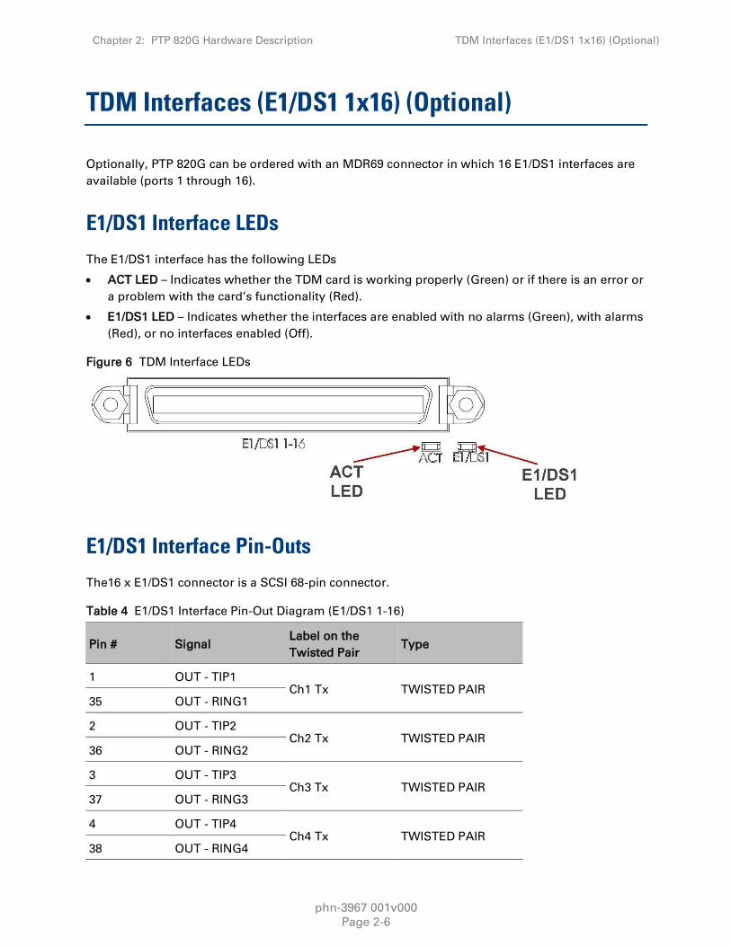
TDM Interfaces (E1/DS1 1x16) (Optional)
Optionally, PTP 820G can be ordered with an MDR69 connector in which 16 E1/DS1 interfaces are
available (ports 1 through 16).
E1/DS1 Interface LEDs
The E1/DS1 interface has the following LEDs
ACT LED – Indicates whether the TDM card is working properly (Green) or if there is an error or
a problem with the card’s functionality (Red).
E1/DS1 LED – Indicates whether the interfaces are enabled with no alarms (Green), with alarms
(Red), or no interfaces enabled (Off).
Figure 6 TDM Interface LEDs
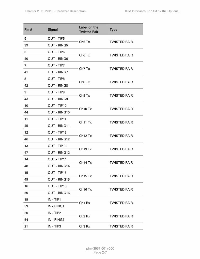
E1/DS1 Interface Pin-Outs
The16 x E1/DS1 connector is a SCSI 68-pin connector.
Table 4 E1/DS1 Interface Pin-Out Diagram (E1/DS1 1-16)
Pin # Signal Label on the
Twisted Pair Type
1 OUT - TIP1 Ch1 Tx TWISTED PAIR
35 OUT - RING1
2 OUT - TIP2 Ch2 Tx TWISTED PAIR
36 OUT - RING2
3 OUT - TIP3 Ch3 Tx TWISTED PAIR
37 OUT - RING3
4 OUT - TIP4 Ch4 Tx TWISTED PAIR
38 OUT - RING4
Chapter 2: PTP 820G Hardware Description TDM Interfaces (E1/DS1 1x16) (Optional)
phn-3967 001v000
Page 2-7
Pin # Signal Label on the
Twisted Pair Type
5 OUT - TIP5 Ch5 Tx TWISTED PAIR
39 OUT - RING5
6 OUT - TIP6 Ch6 Tx TWISTED PAIR
40 OUT - RING6
7 OUT - TIP7 Ch7 Tx TWISTED PAIR
41 OUT - RING7
8 OUT - TIP8 Ch8 Tx TWISTED PAIR
42 OUT - RING8
9 OUT - TIP9 Ch9 Tx TWISTED PAIR
43 OUT - RING9
10 OUT - TIP10 Ch10 Tx TWISTED PAIR
44 OUT - RING10
11 OUT - TIP11 Ch11 Tx TWISTED PAIR
45 OUT - RING11
12 OUT - TIP12 Ch12 Tx TWISTED PAIR
46 OUT - RING12
13 OUT - TIP13 Ch13 Tx TWISTED PAIR
47 OUT - RING13
14 OUT - TIP14 Ch14 Tx TWISTED PAIR
48 OUT - RING14
15 OUT - TIP15 Ch15 Tx TWISTED PAIR
49 OUT - RING15
16 OUT - TIP16 Ch16 Tx TWISTED PAIR
50 OUT - RING16
19 IN - TIP1 Ch1 Rx TWISTED PAIR
53 IN - RING1
20 IN - TIP2 Ch2 Rx TWISTED PAIR
54 IN - RING2
21 IN - TIP3 Ch3 Rx TWISTED PAIR

Chapter 2: PTP 820G Hardware Description TDM Interfaces (E1/DS1 1x16) (Optional)
phn-3967 001v000
Page 2-8
Pin # Signal Label on the
Twisted Pair Type
55 IN - RING3
22 IN - TIP4 Ch4 Rx TWISTED PAIR
56 IN - RING4
23 IN - TIP5 Ch5 Rx TWISTED PAIR
57 IN - RING5
24 IN - TIP6 Ch6 Rx TWISTED PAIR
58 IN - RING6
25 IN - TIP7 Ch7 Rx TWISTED PAIR
59 IN - RING7
26 IN - TIP8 Ch8 Rx TWISTED PAIR
60 IN - RING8
27 IN - TIP9 Ch9 Rx TWISTED PAIR
61 IN - RING9
28 IN - TIP10 Ch10 Rx TWISTED PAIR
62 IN - RING10
29 IN - TIP11 Ch11 Rx TWISTED PAIR
63 IN - RING11
30 IN - TIP12 Ch12 Rx TWISTED PAIR
64 IN - RING12
31 IN - TIP13 Ch13 Rx TWISTED PAIR
65 IN - RING13
32 IN - TIP14 Ch14 Rx TWISTED PAIR
66 IN - RING14
33 IN - TIP15 Ch15 Rx TWISTED PAIR
67 IN - RING15
34 IN - TIP16 Ch16 Rx TWISTED PAIR
68 IN - RING16
17 SHELL - SHIELD
18 SHELL - SHIELD

Chapter 2: PTP 820G Hardware Description TDM Interfaces (E1/DS1 1x16) (Optional)
phn-3967 001v000
Page 2-9
Pin # Signal Label on the
Twisted Pair Type
51 SHELL - SHIELD
52 SHELL - SHIELD

Chapter 2: PTP 820G Hardware Description Radio Interfaces
phn-3967 001v000
Page 2-10
Radio Interfaces
PTP 820G includes one or two radio interfaces, depending on the hardware assembly option that
was selected. Each radio interface uses a TNC connector type. Each radio interface is connected to
an RFU via coaxial cable. This connection is used for traffic between the RFU and the IDU. It is also
used to provide -48V DC power from the IDU to the RFU, as well as for management and
configuration of the RFU.
The radio interfaces are labeled Radio 1 and, if there is a second radio interface, Radio 2.
Radio Interface LEDs
Each radio interface has the following set of LEDs. The LEDs for Radio 1 are located to the right of
the interface. The LEDs for Radio 2 are located to the left of the interface.
The LEDs indicate the following:
ACT – Indicates whether the interface is working properly (Green) or if there is an error or a
problem with the interface’s functionality (Red), as follows:
o Off – The radio is disabled.
o Green – The radio is active and operating normally.
o Blinking Green – The radio is operating normally and is in standby mode.
o Red – There is a hardware failure.
o Blinking Red – Troubleshooting mode.
LINK – Indicates the status of the radio link, as follows:
o Green – The radio link is operational.
o Red – There is an LOF or Excessive BER alarm on the radio.
o Blinking Green – An IF loopback is activated, and the result is OK.
o Blinking Red – An IF loopback is activated, and the result is Failed.
RFU – Indicates the status of the RFU, as follows:
o Green – The RFU is functioning normally.
o Yellow – A minor RFU alarm or a warning is present, or the RFU is in TX mute mode, or, in
a protected configuration, the RFU is in standby mode.
o Red – A cable is disconnected, or a major or critical RFU alarm is present.
o Blinking Green – An RF loopback has been activated, and the result is OK.
o Blinking Red – An RF loopback has been activated, and the result is Failed.

Chapter 2: PTP 820G Hardware Description Radio Interfaces
phn-3967 001v000
Page 2-11
Figure 7 Radio Interface LEDs

Chapter 2: PTP 820G Hardware Description Power Interfaces
phn-3967 001v000
Page 2-12
Power Interfaces
PTP 820G receives an external supply of -48V current via one or two power interfaces (the second
power interface is optional for power redundancy). The PTP 820G monitors the power supply for
under-voltage and includes reverse polarity protection, so that if the positive (+) and negative (-)
inputs are mixed up, the system remains shutdown.
The allowed power input range for the PTP 820G is -40V to -60V. An under voltage alarm is
triggered if the power goes below the allowed range, and an over voltage alarm is triggered if the
power goes above the allowed range.
Power Interface LEDs
There is an ACT LED for each power interface. The LED is Green when the voltage being fed to the
power interface is within range, and Red if the voltage is not within range or if a power cable is not
connected.
Figure 8 Power Interface LEDs

Chapter 2: PTP 820G Hardware Description Synchronization Interface
phn-3967 001v000
Page 2-13
Synchronization Interface
PTP 820G includes an RJ-45 synchronization interface for T3 clock input and T4 clock output. The
interface is labeled SYNC.
Synchronization Interface LEDs
The synchronization interface contains two LEDs, one on the upper left of the interface and one on
the upper right of the interface, as follows:
T3 Status LED – Located on the upper left of the interface. Indicates the status of T3 input clock,
as follows:
o Off – There is no T3 input clock, or the input is illegal.
o Green – There is legal T3 input clock.
T4 Status LED – Located on the upper right of the interface. Indicates the status of T4 output
clock, as follows:
o Off – T4 output clock is not available.
o Green – T4 output clock is available.
o Blinking Green – The clock unit is in a holdover state.
Figure 9 Sync Interface LEDs
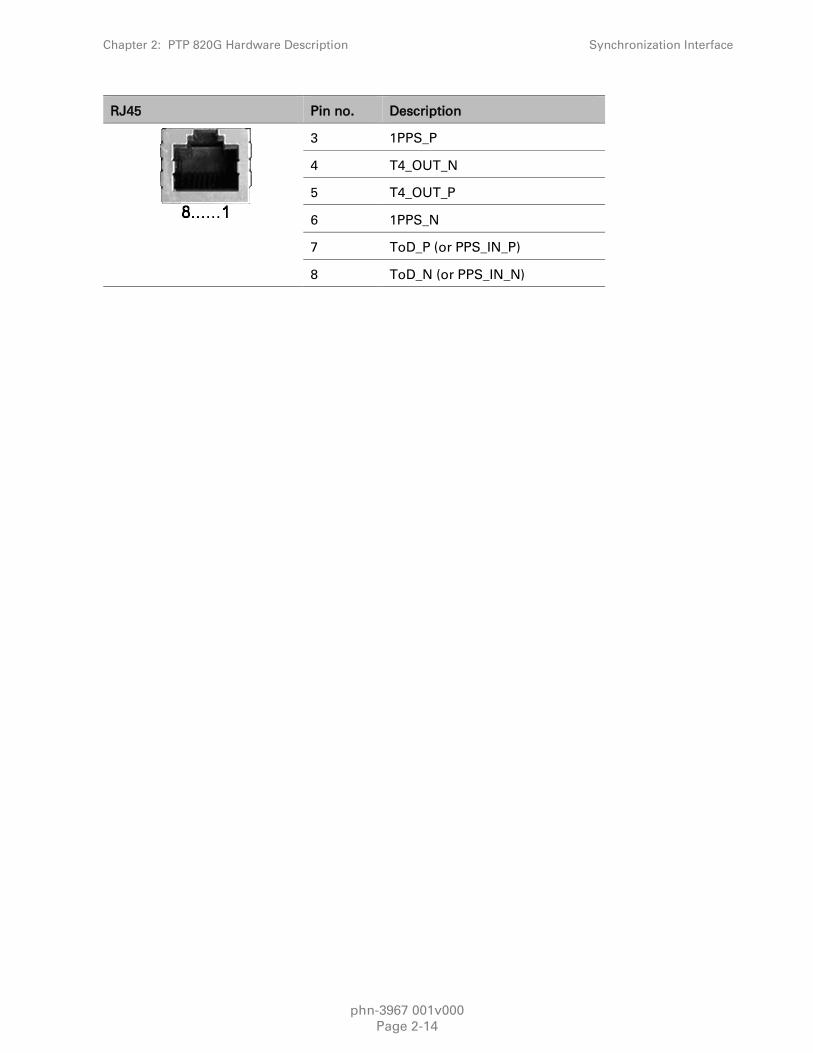
Synchronization Interface Pin-Outs
Table 5 Synchronization Interface Pin-Out Diagram
RJ45 Pin no. Description
1 T3_IN_N
2 T3_IN_P
Chapter 2: PTP 820G Hardware Description Synchronization Interface
phn-3967 001v000
Page 2-14
RJ45 Pin no. Description
3 1PPS_P
4 T4_OUT_N
5 T4_OUT_P
6 1PPS_N
7 ToD_P (or PPS_IN_P)
8 ToD_N (or PPS_IN_N)
Chapter 2: PTP 820G Hardware Description Terminal Interface
phn-3967 001v000
Page 2-15
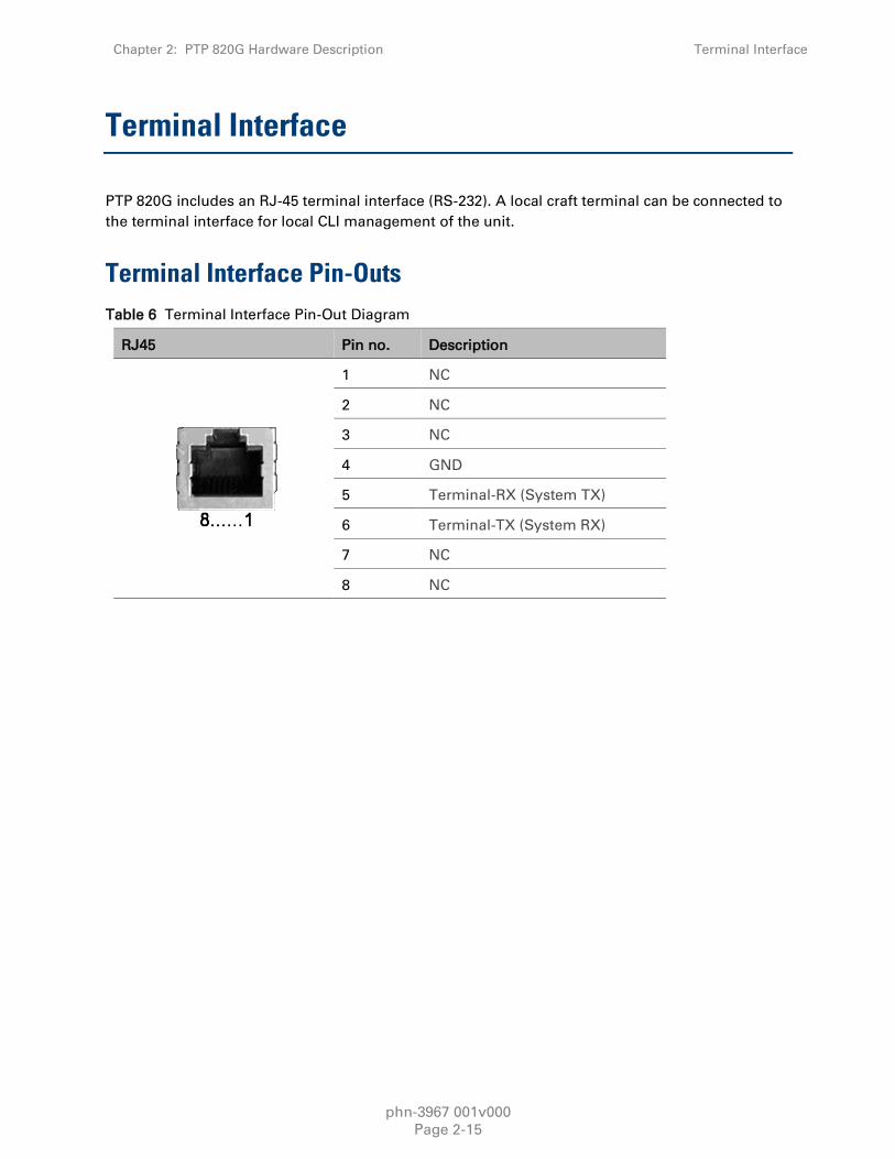
Terminal Interface
PTP 820G includes an RJ-45 terminal interface (RS-232). A local craft terminal can be connected to
the terminal interface for local CLI management of the unit.
Terminal Interface Pin-Outs
Table 6 Terminal Interface Pin-Out Diagram
RJ45 Pin no. Description
1 NC
2 NC
3 NC
4 GND
5 Terminal-RX (System TX)
6 Terminal-TX (System RX)
7 NC
8 NC

Chapter 2: PTP 820G Hardware Description External Alarms
phn-3967 001v000
Page 2-16
External Alarms
PTP 820G includes a DB9 dry contact external alarms interface. The external alarms interface
supports five input alarms and a single output alarm.
The input alarms are configurable according to:
1 Intermediate
2 Critical
3 Major
4 Minor
5 Warning
The output alarm is configured according to predefined categories.
External Alarm Pin-Outs
Table 7 External Alarm Interface Pin-Out Diagram
DB-9 Pin no. Description
1 External input alarm #1
2 External input alarm #2
3 External input alarm #3
4 External input alarm #4
5 External input alarm #5
6 Relay #1, normally closed pin
7 Relay #1, common pin
8 Relay #1, normally open pin
9 GND

Chapter 2: PTP 820G Hardware Description Unit/ACT LED
phn-3967 001v000
Page 2-17
Unit/ACT LED
A general ACT LED for the unit is located on the lower left of the PTP 820G front panel. This LED is
labeled UNIT/ACT, and indicates the general status of the unit, as follows:
Off – Power is off.
Green – Power is on, and no alarms are present on the unit.
Yellow – Power is on, and there are minor alarms or warnings on the unit.
Red – Power is on, and there are major or critical alarms on the unit.
Figure 10 Unit/ACT LED

phn-3967 001v000
Page 3-1
Chapter 3: Preparation for Installation
This section provides instructions for transporting, inspecting and unpacking the equipment for a
PTP 820G system prior to installation.

Chapter 3: Preparation for Installation Transportation/Storage
phn-3967 001v000
Page 3-2
Transportation/Storage
The equipment cases are prepared for shipment by air, truck, railway and sea, suitable for
handling by forklift trucks and slings. The cargo must be kept dry during transport and storage.
For sea-transport, deck-side shipment is not permitted. Carrier-owned cargo containers must be
used.
It is recommended that the equipment is transported to the installation site in its original packing
cases.
If any intermediate storing is required, all cases must be stored under dry and cool conditions and
out of direct sunlight.

Chapter 3: Preparation for Installation Inspection
phn-3967 001v000
Page 3-3
Inspection
Check the packing lists and ensure that correct parts numbers quantities of goods have arrived.
Inspect for any damage on the cases and equipment. Report any damage or discrepancy to a
Cambium Networks support team (http://www.cambiumnetworks.com/support).

Chapter 3: Preparation for Installation Unpacking Equipment at the Site
phn-3967 001v000
Page 3-4
Unpacking Equipment at the Site
The equipment is packed in sealed plastic bags and moisture absorbing bags are inserted. Any
separate sensitive products such as printed boards, are packed in anti-static handling bags. The
equipment is further packed in special designed cases.
Marking is done according to standard practice unless otherwise specified by customers.
Customers address
Contract No
Site name (if known)
Case No
Dimensions and weight of each case are specified in the packing specification issued for the
respective shipment.
Caution
It is essential that whenever unpacking or disassembling the equipment and handling
printed circuit boards, special precautions must be taken to avoid ESD (Electrostatic
Static Discharge). Generally, units with static discharge protection must not be
unpacked until the installation takes place.
Ensure you are properly grounded at a controlled ESD point before and during
unpacking and handling of any sensitive component.
To avoid malfunctioning or personnel injuries, equipment or accessories/kits/plug-in
unit installation, requires qualified and trained personnel.
Changes or modifications not expressly approved by Cambium Networks could void
the user's authority to operate the equipment
Where special cables, shields, adapters and grounding kits are supplied or described
in this manual, these items must be used, to comply with the relevant regulations

phn-3967 001v000
Page 4-1
Chapter 4: Installing the PTP 820G
This section provides instructions for installing a PTP 820G IDU.
Figure 11 IDU (Full Configuration)
Kits required to perform the installation
Table 8 Required Kits for installation
Description Quantity
PTP 820G chassis 1
19" rack / sub-rack 1
SM-Card Cover 1
Tools
Philips screwdriver
Flat screwdriver

Chapter 4: Installing the PTP 820G Unpacking Equipment at the Site
phn-3967 001v000
Page 4-2
Installing the PTP 820G IDU in the Rack (19")
1 Insert and hold the PTP 820G IDU in the rack, as shown in the following figures. Use four
screws (not supplied with the installation kit) to fasten the IDU to the rack.
Figure 12 Fixing IDU to the rack
Grounding the PTP 820G
1 Connect a grounding wire first to the single-point stud shown in the figure below, and then to
the rack, using a single screw and two washers.
Note
The grounding wire must be 16 AWG or thicker.

Chapter 4: Installing the PTP 820G Unpacking Equipment at the Site
phn-3967 001v000
Page 4-3
Figure 13 Connecting a grounding wire
Replacing an PTP 820G IDU or SM-Card
If you must replace the PTP 820G IDU, you have to first remove the SM-Card Cover so that you can
insert it into the new IDU.
The SM-Card holds the configuration and software for the IDU. The SM-Card is embedded in the
SM-Card Cover, so re-using the existing SM-Card Cover is necessary to ensure that the unit’s
software and configuration is maintained.
In some cases, you may need to replace the SM-Card itself in order to upgrade the unit’s
configuration.
To remove the SM-Card Cover:

Chapter 4: Installing the PTP 820G Unpacking Equipment at the Site
phn-3967 001v000
Page 4-4
1 Loosen the screws of the SM-Card Cover and remove it from the IDU.
Figure 14 Removing IDU cover
2 In the new IDU or, if you are upgrading the SM-Card, the old IDU, make sure that there is no
foreign matter blocking the sockets in the opening where the SM-Card is installed.
Figure 15 SM card
3 Gently place the SM-Card Cover in its place and tighten the screws, using a Phillips
screwdriver.
phn-3967 001v000
Page 5-1
Chapter 5: Connecting Power Cable
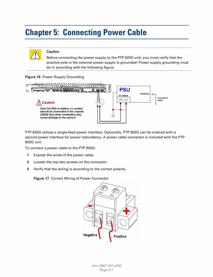
Caution
Before connecting the power supply to the PTP 820G unit, you must verify that the
positive pole in the external power supply is grounded! Power supply grounding must
be in according with the following figure:
Figure 16 Power Supply Grounding
PTP 820G utilizes a single-feed power interface. Optionally, PTP 820G can be ordered with a
second power interface for power redundancy. A power cable connector is included with the PTP
820G unit.
To connect a power cable to the PTP 820G:
1 Expose the wires of the power cable.
2 Loosen the top two screws on the connector.
3 Verify that the wiring is according to the correct polarity.
Figure 17 Correct Wiring of Power Connector
Chapter 5: Connecting Power Cable Unpacking Equipment at the Site
phn-3967 001v000
Page 5-2
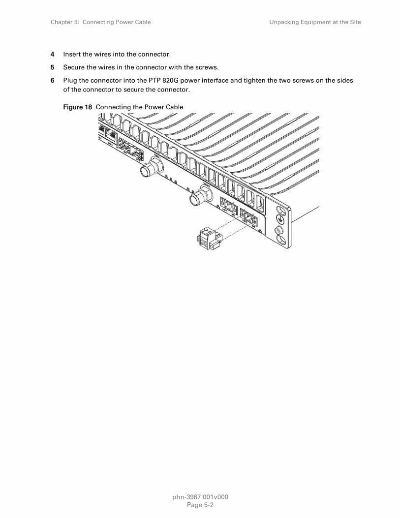
4 Insert the wires into the connector.
5 Secure the wires in the connector with the screws.
6 Plug the connector into the PTP 820G power interface and tighten the two screws on the sides
of the connector to secure the connector.
Figure 18 Connecting the Power Cable

Chapter 5: Connecting Power Cable Power Supply Notes
phn-3967 001v000
Page 5-3
Power Supply Notes
When selecting a power source, the following must be considered:
Voltage range: -40 VDC to -60 VDC.
Recommended: Availability of a UPS (Uninterrupted Power Source), battery backup, and
emergency power generator.
The power source must be grounded.
The unit has more than one supply connection - Remove all power from the unit for servicing.
Warning
Make sure to use a circuit breaker to protect the circuit from damage by short or
overload. In a building installation, the circuit breaker shall be readily accessible and
incorporated external to the equipment. The maximum rating of the overcurrent
protection shall be 10 Amp, while the maximum current rating is 5 Amp.

phn-3967 001v000
Page 6-1
Chapter 6: Performing Initial Configuration
This section describes how to establish a management connection with the PTP 820G unit and lists
the configuration steps that must be performed in order to enable basic radio connectivity. For
detailed configuration instructions, refer the PTP 820G User Guide.

Chapter 6: Performing Initial Configuration Establishing a Connection
phn-3967 001v000
Page 6-2
Establishing a Connection
You can connect to the PTP 820G unit using a TP cable with a LAN connection or using a Serial RS-
232 cable.
Connecting to the Unit with a Serial Connection
1 Connect an RS-232 cable with an RJ-45 interface from your laptop or PC to the Terminal
Interface on the PTP 820G front panel.
Figure 19 Terminal Interface
2 Configure the following settings for the COM port you are using on your PC or laptop:
Bits per Second – 115,200
Data Bits – 8
Parity – None
Stop Bits – 1
Flow Control - None
PTP 820G contains two FE management interfaces, which connect to a single RJ-45 physical
connector on the front panel (MGMT). For details on which type of cable to use to utilize either one
or both management interfaces, see Management Interface Cable Options on page 2-4.
Connect the cable to Management interface (MGMT) on the PTP 820G front panel, and to the LAN
port on the PC.
Figure 20 Management Interface

Chapter 6: Performing Initial Configuration Establishing a Connection
phn-3967 001v000
Page 6-3
To establish a connection between the PC and the PTP 820G unit, it is necessary to have an IP
address on the PC within the same subnet as the unit. The default IP address of the PTP 820G unit
is 192.168.1.1. Set the PC address to e.g. 192.168.1.10 and subnet mask to 255.255.255.0.
Note
The initial settings before changing.
Note
The chassis IP address, as well as password must be changed before setting the
system in operation. For more information on these procedures, see PTP 820G User
Guide.
1 Select Control Panel > All Control Panel Items > Network and Sharing Center.
2 Click Change adapter settings.
3 Select Local Area Connection > Properties > Internet Protocol Version 4 (TCP/IP).
IP address: 192.168.1.10
Subnet mask 255.255.255.0
No default gateway
4 Press OK to apply the settings.

Chapter 6: Performing Initial Configuration Logging On
phn-3967 001v000
Page 6-4
Logging On
1 Open a browser (e.g. Internet Explorer, Mozilla Firefox etc).
2 Type in the default IP address "192.168.1.1" in the Address Bar.
Login Window
3 Enter the following values:
User Name: admin
Password: admin
4 Click Apply.

Chapter 6: Performing Initial Configuration Configuration
phn-3967 001v000
Page 6-5
Configuration
Before connection over the radio hop is established, it is of high importance that the elements are
assigned a dedicated IP address, according to an IP plan for the total network.
Note
If connection over the hop is established with identical IP addresses, an IP address
conflict will occur and remote connection to the element on the other side of the hop
may be lost.
By default all elements have the same IP settings:
IP address: 192.168.1.1
Subnet mask: 255.255.255.0
Note
After the new IP address is set, the contact with the element will be lost. In order to
reconnect, the PC must have an IP address within the same subnet as the element.
In addition to setting the IP addresses, the following configuration steps must be performed in
order to establish basic connectivity. For a detailed description of these procedures, refer the PTP
820G User Guide.
Enable the Radio Interfaces
Set the Radio Frequencies
Configure the License
Unmute the Radio

phn-3967 001v000
Page 7-1
Chapter 7: Specifications
Environmental Specifications for IDU
Operating: ETSI EN 300 019-1-3 Class 3.2
Temperature:
o -5C (23F) to 55C (131F) – Temperature range for continuous operating temperature with
high reliability.
o -25C (-13F) to 65C (149F) – Temperature range for exceptional temperatures, tested
successfully, with limited margins.
Note
Cold startup requires at least -5C (23F)
Humidity: 5%RH to 95%RH
Environmental Specifications for RFU
Operating: ETSI EN 300 019-1-4 Class 4.1
Temperature:
o -33C (-27F) to +55C (131F) – Temperature range for continuous operating temperature
with high reliability:
o -45C (-49F) to +60C (140F) – Temperature range for exceptional temperatures; tested
successfully, with limited margins:
Humidity: 5%RH to 100%RH
Mechanical Specifications
Table 9 IDU Mechanical Specifications
IDU Dimensions
Height: 44 mm/1.73” (1RU)
Width: 426 mm/16.77”
Depth: 180 mm/7.08”
Weight: 2.5 kg/5.5 lbs.
IDU-RFU Connection
Coaxial cable RG-223 (300 ft), Belden 9914/RG-8
(1000 ft) or equivalent, TNC connectors to the IDU, N-
type connectors (male) to the RFU.

Chapter 7: Specifications Configuration
phn-3967 001v000
Page 7-2
Table 10 RFU-C Mechanical Specifications
RFU-C Dimensions
Height: 200 mm/7.87”
Width: 200 mm/7.87”
Depth: 85 mm/3.35”
Weight: 4kg/9 lbs.
RFU-C Standard
Mounting OD Pole
50 mm-120 mm/2”-4.5” (subject to vendor and antenna
size)
Power Consumption Specifications
The following table shows the maximum power consumption for PTP 820G IDU and supported
RFUs. The maximum power consumption for the entire system is the sum of the IDU and the RFUs
connecting to it.
Table 11 Power Consumption specifications
Configuration Power (W) Comments
IDU Eth-only with single RFU 23.5W
Addition for second RFU 2.9W
Addition for 16 E1s 11W
RFU-C
1+0: 22
1+1: 39 RFU only.
1+0: 26
1+1: 43 RFU only.