call setup delay analysis of h.323 and sip
TRANSCRIPT

Technical report, IDE1121, March 2011
Call Setup Delay Analysis of H.323 and SIP
Master’s Thesis in Computer Network Engineering
Mukesh Malliah & Umer Babar
School of Information Science, Computer and Electrical Engineering Halmstad University

Call Setup Time Analysis of H.323 and SIP
Master Thesis in Computer Network Engineering
School of Information Science, Computer and Electrical Engineering
Halmstad University
Box 823, S-301 18 Halmstad, Sweden
March 2011


Call Setup Delay Analysis of H.323 and SIP
1
Preface
We would like to thank Halmstad University for giving us a platform to complete our Master Thesis.
We are also whole heartedly thankful to Tony Larsson and Wagner Ourique de Morais, who
supported us in finishing our thesis work in a successful way.
We would also like to thank our fellow course mates who helped us in our studies.
Mukesh Malliah & Umer Babar
Halmstad University, March 2011
Abstract
IP Telephony is a technology which uses internet and signalling protocols like H.323 and SIP
to setup and transfer voice signals from one destination to another. These protocols use
various encoding schemes to transmit voice signals over the digital technology. The success
of IP Telephony is the cost and time effectiveness; hence we studied on the call setup delay
of these two signaling protocols H.323 and SIP.
H.323 uses TCP and SIP uses UDP as transport protocols to set up a call. They have different
scopes that distinguish them. The signalling protocols H.323 and SIP call setup delays are
observed and studied successfully between the traditional telephones and IP telephones. The
call setup delay for H.323 is analysed experimentally in the Cisco environment by
establishing calls at various loads such as null load, medium load and heavy load. Due to
practical difficulties the SIP call setup delay is studied only literally. The parameters that we
considered for our experiments are the average call setup delay, bandwidth and different
traffic loads. Finally, the results of both H.323 and SIP are compared with each other to find
out the best signalling protocol. The comparison is done according to the call setup delay and
other factors like complexity, compatibility, reliability and bandwidth utilization.
.
Call Setup Delay Analysis of H.323 and SIP
3
List of Acronyms
ATM Asynchronous Transfer Mode
ACELP Algebraic Code Excitation
CO Central Office
CM Cisco Call Manager
DUAL Diffusing Update Algorithm
E1 E-Carrier
EKTS Electronic Key Telephone System
EIGRP Enhanced Interior Gateway Routing Protocol
FTP File Transfer Protocol
GW Gateway
GK Gatekeeper
HDLC High Level Data Link
HTTP Hypertext Transfer Protocol
IP Internet Protocol
ITU International Telecommunication Union
IETF Internet Engineering Task Force
IEEE Institute of Electrical and Electronics Engineers
IGRP Interior Gateway Routing Protocol
KTS Key Telephone System
LAN Local Area Network
LLC Logical Link Control
LS Location Server
MTP Message Transfer Part
MGCP Media Gateway Control Protocol
MAC Media Access Control
MCU Multipoint Conference Unit
MC Multipoint Controller
MP-MLQ Multipulse Maximum Likelihood Quantization
OSI Open System Interconnection
PSTN Public Switched Telephone Network
PBX Private Branch Exchange
PPP Point to Point Protocol
PS Proxy Server

QOS Quality of Service
RTP Real-time Transport Protocol
RAS Registration, Admission and Status
RTCP Real-Time Transmission Control Protocol
SIP Session Initiation Protocol
SDP Session Description Protocol
SS7 Signaling System 7
SMTP Simple Mail Transfer Protocol
SP Soft Phone
T1 T- carrier
TG Traffic Generator
TCP Transmission Control Protocol
UDP User Datagram Protocol
UAC User Agent Client
UAS User Agent Server
VoIP Voice over Internet Protocol
VLAN Virtual Local Area Network
WAN Wide Area Network
WS Wireshark Tool

Call Setup Delay Analysis of H.323 and SIP
5
Contents
PREFACE ...................................................................................................................................................... 1
ABSTRACT .................................................................................................................................................... 2
CONTENTS ................................................................................................................................................... 6
1 INTRODUCTION ................................................................................................................................. 9
1.1 APPLICATION AREA AND MOTIVATION ................................................................................................ 9
1.2 PROBLEM STATEMENT ......................................................................................................................... 9
1.3 GOALS AND EXPECTED RESULTS ......................................................................................................... 9
2 BACKGROUND ................................................................................................................................. 11
2.1 IP TELEPHONY BACKGROUND ........................................................................................................... 11
2.2 SIGNALLING SYSTEM 7 (SS7) ............................................................................................................. 11
2.3 VOICE OVER IP PROTOCOL ................................................................................................................ 11
2.3.1 Voice over IP ........................................................................................................................... 11
2.3.2 The OSI Open System Interconnection ..................................................................................... 11
2.3.3 Voice traffic Management by OSI............................................................................................. 13
2.4 H.323 ............................................................................................................................................... 14
2.4.1 H.255 ...................................................................................................................................... 14
2.4.2 Q.931 ...................................................................................................................................... 15
2.4.3 H.245 Control Signaling .......................................................................................................... 15
2.5 SIP ................................................................................................................................................... 15
2.5.1 Why SIP .................................................................................................................................. 16
2.5.2 SIP Components ...................................................................................................................... 16
2.6 COMPARISON OF H.323 AND SIP ........................................................................................................ 18
2.7 EIGRP .............................................................................................................................................. 19
3 SOLUTION TO BE INVESTIGATED ............................................................................................... 20
3.1 CALL SETUP TIME ............................................................................................................................. 20
3.1.1 Call setup time......................................................................................................................... 20
3.1.2 Call Setup on H.323 and SIP ................................................................................................... 20
3.2 H.323 CALL SETUP............................................................................................................................ 21
3.3 SIP SESSION SETUP ........................................................................................................................... 22
3.4 G.723.1 ............................................................................................................................................ 23
4 NETWORK TOPOLOGY .................................................................................................................. 24
4.1 NETWORK TOPOLOGY OF H.323 CALL SETUP ..................................................................................... 24
4.1.1 Call Flow Diagram of H.323 ................................................................................................... 26
4.2 NETWORK TOPOLOGY OF SIP CALL SETUP .......................................................................................... 28
4.2.1 Call Flow Diagram of SIP ....................................................................................................... 28
4.3 TRANSMISSION CONTROL PROTOCOL (TCP) ....................................................................................... 30
4.4 USER DATAGRAM PROTOCOL (UDP) ................................................................................................. 30
Call Setup Delay Analysis of H.323 and SIP
7
4.5 REAL-TIME TRANSPORT PROTOCOL (RTP) .............................................................................. 31
5 RESULTS ............................................................................................................................................ 32
5.1 CALL SETUP RESULTS ON H.323 ........................................................................................................ 32
5.2 TRAFFIC GENERATED ........................................................................................................................ 32
5.3 CALL SETUP AT VARIOUS LOADS ........................................................................................................ 34
5.3.1 No Load .................................................................................................................................. 34
5.3.2 Medium Load .......................................................................................................................... 35
5.3.3 Heavy Load ............................................................................................................................. 39
5.4 CALL SETUP DELAY RESULTS ON SIP ................................................................................................. 43
6 CONCLUSION ................................................................................................................................... 44
7 REFERENCES .................................................................................................................................... 45


Call Setup Delay Analysis of H.323 and SIP
9
1 INTRODUCTION
1.1 Application Area and Motivation
The technology recently introduced in the telecommunication industry is IP telephony. The
major concept of IP telephony is to transfer voice messages through networks using internet
protocol. The main task of IP telephony is to transmit the multimedia messages such as video
and voice in the form of data packets. IP telephony follows the recommendations created by
the Internet Engineering Task Force (IETF) and International Telecommunication Union
(ITU). The major benefit of internet telephony is to reduce the charges of long distance calls
to the local call rate. In addition to this, it also transmits all kinds of data types like video,
voice and data in a single medium by assuming the IP protocol as the mutual protocol. [1][2]
To support voice over internet telephony protocols such as H.323, SIP, MGCP, Megaco are
used along with the number of encoding techniques (CODECs) like G.711, G.723, G.726,
G.728 and G.729 according to the user‟s requirements and the capability of the network.
Even though IP Telephony is cost effective, it has some factors that affects it better qualities
such as packet loss, call setup delay, packet delay, Jitter and end to end delay.
In IP telephony, the first factor which affects the quality of service in transmitting voice
packets is the call setup delay. The call setup delay is the time interval between the last digit
dialed and receiving the ring tone back. The call setup delay depends on the transport
protocol used for call establishment. [11]
H.323 and SIP are the most competing signaling protocols of IP telephony in which H.323
works on TCP and SIP works on UDP. The two major signaling protocols H.323 and SIP use
different transport protocols TCP and UDP for transmitting voice packets over the internet.
This specific concept motivated us to work on the call setup delay time properties of the
signaling protocols H.323 and SIP over IP telephony.
1.2 Problem Statement
In telecommunication, IP telephony is successful technology invented to transfer voice
packets over the internet and also between IP telephones and traditional telephones. It is
successful because of cost and time effectiveness. To handle IP telephony more efficiently,
we have many signaling protocols; and the most competing protocols are H.323 by ITU and
SIP by IETF. [7]
H.323 and SIP work on different conditions and have different features. For example, H.323
uses TCP for connection establishment whereas SIP uses UDP. They also have their own
merits and demerits. As we mentioned earlier in this section, IP Telephony is good because of
it features such as low cost and less call setup delay. However, if the organisations looking
for the services of H.323, which is very expensive and complex then why are they not ready
to use SIP?
1.3 Goals and Expected Results
The major goal of our thesis is to find out the call setup delay on both signaling protocols
H.323 and SIP.
A sub goal is to setup a test environment between local exchange and foreign exchange using
H.323 signaling protocol in the Cisco environment. Then we make a number of calls between

the two exchanges over three types of traffic to find out the average call setup delay of H.323
signaling protocol.
The call setup delay for the SIP signalling protocol is studied theoretically. Finally the
experimental results of H.323 call setup delay is compared with the theoretical call setup
delay of SIP signalling protocol that thus only is studied theoretically.
The expected result of our thesis is that the signalling protocol H.323 may consume more
time than the SIP signalling protocol measured call setup delay. However the call setup delay
of two signaling protocols might also be very similar.

Call Setup Delay Analysis of H.323 and SIP
11
2 BACKGROUND
2.1 IP Telephony Background
In a basic telephone system, a call can be made by a user only with the help of basic
telephone. If a user wants to make a call to the destination, the call should pass various stages
before it reach the destination. The steps are the call should reach the company internal phone
system or to the Public Switched Telephone Network (PSTN) through analog trunk or
through digital trunk like T1/E1. After this the call reaches the destination from PSTN. Here
the calls are transmitted through transmitting equipment‟s like copper cables, fibre optic
cables, microwave communications and satellite communications. [2]
The important traditional telephony equipment‟s are a KTS- Key Telephone System, EKTS-
Electronic Key Telephone Systems, PBX- Private Branch Exchange, CO- Central Office and
Toll Switch which helps to implement the traditional telephony system. [2]
Later this telephony system was advanced to the new IP telephony method in which the
internet plays a major role with the help of signalling protocols like H.323, SIP, and so on
and also with various encoder schemes derived by the ITU and the IETF. This telephony
system reduced the cost and effort significantly when compared to the basic telephony
system. [2]
2.2 Signalling System 7 (SS7)
SS7 is an ITU-T standard came to use in 1987. SS7 is for the administration purpose of the
traditional telecommunication systems. Message Transfer Part (MTP) and Signalling
Connection Control Part (SCCP) are the two major parts of SS7 and because of SCCP errors
and frauds are reduced and also the call setup and take downs are performed faster as it works
out of band. [2]
The two major functionalities of SS7 are that it allows the end party know the details of the
called party and also it connects the call setup fast with the help of dedicated circuit switched
connections. [2]
2.3 Voice over IP Protocol
2.3.1 Voice over IP
Voice over Internet Protocol (VoIP) significant benefits as it uses Internet Protocol for the
transport mechanism to make calls from a regular telephone or from soft phones. VoIP
transmits packets between the same service providers and also it allows the making of calls to
a normal telephone number. The data transmission over the internet between various devices
is performed successfully by the concept of an OSI model. [4]
2.3.2 The OSI Open System Interconnection
Physical Layer
The physical link between the called party and the end party is activated, maintained and
deactivated by the physical layer which sets electrical, mechanical, procedural and functional
specifications. The categories in physical layer implementations are LAN and WAN
specifications. [2]
Data Link layer
The reliable service of transmitting the data through the physical link layer is carried out by
the data link layer. Network and protocol characteristics such as physical addressing, network
topology, error notification, frame sequencing and flow control are varied according to the
specifications mentioned in the data link layer.
The two sub layers present in the data link layer are,
1. MAC (Media access control)
2. LLC (Logical link control)
The LLC sub layer which supports both connectionless and connection oriented network
is defined by the IEEE 802.2 specifications. The function of LLC is to manage the
connection between the devices. The functionality of MAC sub layer is to manage the
protocol access to the physical network. In order to identify one device among the
multiple devices present in the network, it enables the MAC address which is unique to
each device, defined by the IEEE MAC specifications. [2]
Network Layer
The network layer implementations such as Internet Protocol (IP), defines the network
address which completely differs from the MAC address. As the logical network layout is
defined by this layer, the routers can easily determine the way to forward the packets. Hence
at the layer 3, all the design and implementation works for the internetworks are
implemented. [2]
Transport layer
In the transport layer, the data is received from the session layer, they are then analysed for
errors and then the data is segmented and aligned in a sequence before they are dropped in
the transport layer to transmit the data through the network.
This layer performs a major functionality called flow control which manages the data
transmission between the devices according to the sender and receivers adoptability. Other
than this function, multiplexing and error checking are also performed by this transport layer.
TCP and UDP are the two protocols used in the internet as transport protocol. [2]
Session Layer
Establishment, management and termination of sessions between the end users in the network
is done by the session layer using service requests and service responses. The protocols
implemented at the session layer manage the requests and responses co-ordination according
to their functionality. Some examples are ZIP, SCP, Appletalk protocol and DECnet phase IV
session layer protocol. [2]
Presentation layer
The presentation layer handles the functions like coding and conversion that are applicable
for the data from the application layer. These two functions check whether the data sent from
one application layer is readable by the other application layer present at the end user.
Common data representation formats, conversion of character representation formats,
common data compression schemes and common data encryption schemes are the coding and
conversion schemes available in the presentation layer. [2]
Application layer
The application layer is the one in which the user directly interacts with the application layer
through software applications which implement a communicating component. Telnet, File
Transfer Protocol (FTP) and Simple Mail Transfer Protocol (SMTP) are some of the
implementations complete in the application layer. [2]

Call Setup Delay Analysis of H.323 and SIP
13
2.3.3 Voice traffic Management by OSI
In the Application layer, applications such as CISCO IP Communicator and Call Manager
which provide interface to users to generate voice at the PCs and then they convert and
compress the voice signal before passing it to the network. Human speech is considered as an
application and a standard telephone is considered as a user if a gateway is used. [2] [8]
In the Presentation layer, the CODECs are implemented. The CODECs are used to compress
the voice. There are lots of encoding techniques from which the user can select and negotiate
the CODEC which they required according to their process. [2] [8]
In the Session layer the process of implementing the signaling protocol is being handled. The
end to end call signaling methods are defined by H.323 and SIP. The process of separat ing
the signaling function from the voice call function is defined by the protocols MGCP and
Megaco/H.248 and this process is said to be a client/server model for voice signaling. Call
agents are used to control signaling instead of end devices in client/server architecture while
the central control device manages only the call setup function. [2] [8]
OSI Layer Protocols and VoIP Components
Application IP Communicator, Call Manager and Human speech
Presentation CODECs
Session H.323, SIP,MGCP and Megaco
Transport RTP and UDP (media), TCP and UDP (signal)
Network IP
Data link Frame Relay, ATM, Ethernet, Point to Point Protocol (PPP),
Multilink PPP, T1, E1, ISDN BRI, ISDN PRI and High Level Data
Link (HDLC) which supports transport IP packets
Fig (2.3.3) Voice Traffic management by OSI [2]

Physical Category 5 shielded twisted pair (UTP), Coaxial cable, Ethernet
crossover cable and RJ11 are some physical technologies from
which the suitable technology that supports the transport of data
link frames can be chosen here.
Tab (2.3.3) OSI layer and VoIP components [2] [8]
To carry the voice traffic across the network, VoIP implementation has a standard method of
using RTP inside UDP. When the packets reach the destination they are unsynchronized and
out of order. Once the packets reach the end user it should be resynchronized and reordered
before playing. The services like sequence numbers and time stamps are not provided by the
UDP, hence RTP plays a role along with UDP as it provides these functionalities. [2] [8]
The voice packets are ready to transmit across the IP network when they are encapsulated at
the transport layer. Using any kind of data link layer and physical layer which are capable of
transmitting the data, the IP traffic from the network layer is transmitted across the network
to the destination. [2] [8]
2.4 H.323
H.323 is a standard recommended by the International Telecommunication Union (ITU) and
was developed in May of 1996.It works to transmit voice, video, data and fax communication
across an IP-based network connectivity maintained with the PSTN. It encourages the
compatibility in videoconference transmission over IP networks. H.323 was initially
promoted as a way to provide a better performance than other signalling protocols in audio,
video and data packet transmission in the event when LAN did not provide QOS. [7]
H.323 has four components such as give below
Terminals: Probably either traditional telephone or soft phones.
Multipoint conference unit: One of the major duties of MCU is the conference
management. Two major components of the MCU are the Multipoint
Controller (MC) and Multipoint Processors (MP) which helps in managing the
multipoint conference. The MC does not perform the multiplexing of audio
and video but with the help of H.245 it traces the capabilities of the end users.
As well as this, the MP handles multiplexing of data streams with the help of
the MC. [7]
Gateways: This translates the traffic to the format which is required to pass
the packets over the internet at the time of using traditional phone to make a
call without the trouble of the type of traffic. It is the actual endpoint of the
network which makes the two way communication between the end users in
the IP network. [7]
Gatekeeper: It performs various processes like centralized call management;
call admission control, management of bandwidth, address translation for
source and destination, authentication and user location because it is the
important component of H.323 which acts like a manager within its specific
zone. [7]
2.4.1 H.255
The tasks such as registration, admission and status (RAS) are performed by the H.225
standard. To ensure the availability of the connections between the endpoints, gateways and
gatekeepers, the RAS protocol is used. The RAS is used only when the gatekeeper is
available in the network. The RAS handles the tasks such as registration, admission control,
Call Setup Delay Analysis of H.323 and SIP
15
bandwidth changes, and status and withdraw procedures between endpoints and gatekeepers.
[2]
2.4.2 Q.931
Q.931 participates in call control and so it is used to establish a connection between the
terminals and also frames data, because it is a link layer protocol. The major task of the
protocol is to define how each H.323 layer should interact with the peer layers, hence
according to the agreed formats, the participants can exchange information. Q.931 is a part of
H.225. From larger channel, Q.931 can define a logical channel by using a specific method.
With the help of protocol discriminator, Q.931 can easily identify the messages with its call
reference value and message types. The methods of receiving and processing the Q.931
messages are specified by H.225 layers. [2]
2.4.3 H.245 Control Signaling
To connect the H.323 compatible terminals, the H.245 control signalling is used to provide
the call control mechanism. As it carries the control messages to govern the operations over
H.323 endpoints, the H.245 channel is a reliable channel. The information that are carried by
the control messages are
Capabilities Exchange
To open and close logical channels those are used to carry media streams
Preference requests
Flow control messages
General commands and indications [2]
2.5 SIP
SIP is an application control protocol designed by IETF to establish VoIP connections, which
can create, modify and terminate a connection within the end users. The process of SIP is also
similar to HTTP architecture which manages the connection among the end users with the
requests and responses. Simply to say, it is Client-Server architecture. The server and client
exchange the requests and responses to establish a connection. The SIP has two messages
called INVITE and ACK to open a reliable connection through which the call data are passed.
[7]
To carry out the negotiation for codec identification SIP depends on SDP (Session
Description Protocol). To allow the users to work on a set of compatible media types, SIP
supports session descriptions. By the process of proxy and redirecting the requests to the
user‟s current location SIP also helps in User Mobility. [7]
The services provided by SIP are,
User Location: The end system should be determined for communication.
Call Setup: The establishment of call, by ringing from the calling party to the called party.
User Availability: It determines whether the called party is interested to communicate or not.
User Capabilities: To determine the kind of media and the required parameters to support
that media are carried over here.
Call handling: To transfer and to terminate the calls are handled here.

2.5.1 Why SIP
While comparing SIP with H.323, the SIP protocol is simple because it never requires full
compatibility but for H.323 it requires full compatibility. H.323 handles the messages with
binary representation whereas SIP uses only the normal textual representation. SIP is highly
very standard and highly scalable but H.323 is not as much as SIP. In SIP loop detection is
simple with H.323 and also the header space is only 37 in SIP when compared with H.323
which uses more than hundred. Hence many telecom industries looking trying to use SIP in
the place of H.323. [7]
2.5.2 SIP Components
1) User Agents
2) Network Server
User Agents
On behalf of a User, the user agent acts as an end System. It has 2 parts, Client and Server.
Client is known as User Agent Client (UAC) and Server as User Agent Server (UAS). UAC
indicates the SIP Request and the UAS receives the SIP request and sends responses to the
UAC on behalf of user.
Network Server
Here we use 3 servers together in a network.
Registration server: Registers the current location of the user
Proxy Server: It receives requests and forwards them to the next hop server, which provides
more information about the called party.
Redirect Server: This server on receiving the request determines the next hop server and
returns the address of the next hop server to the client instead of forwarding the request. [7]
2.5.3 Overview of SIP operation
The messages are used for the communication between the client and the server. Those
messages are,
Fig (2.5.3) Formation of SIP operation [7]

Call Setup Delay Analysis of H.323 and SIP
17
SIP Messages
INVITE: invites a user to make a call
BYE: terminate a connection between the 2 end users
ACK: makes a reliable exchange of invitation messages
OPTIONS: to find information about what capabilities do the call has.
REGISTER: the SIP registration server gets the details about the location of the user.
CANCEL: it terminates the process of searching for a user.
The SIP address is used to identify the callers and callees. The caller first identifies the SIP
server and sends a request. The caller can connect the callees directly or through some servers
called redirect servers. The calls are uniquely identified by the call ID field in the SIP
message. [7]
SIP Addressing
The SIP URL which is in the form sip:username@host is used to identify the SIP host. The
SIP address can be for an individual or for a group.
Locating the SIP server
The request from the client can be sent directly to the IP address or port corresponding to the
Uniform Request Identifier UDP or to the SIP proxy server. [7]
SIP Transaction
The client can send requests to the server when the host part of the Request URI has been
resolved to a SIP server. Then a SIP transaction can be made triggering a request along with
the response for the request made by the client. Through a reliable TCP or through an
unreliable UDP the can be sent between the end users. [7]
SIP Invitation
An INVITE followed by ACK is the two requests required to perform a successful SIP
Invitation. To make a callee participate in a specific conference call or in a two party
conversation, the INVITE request is used. By sending an ACK request from the caller the
caller confirms the callee, after the callee agreed to participate in the call. A session
description in the INVITE request provides enough information to the called party to join the
session. By sending a similar description to the invitation as a response, the callee expresses
its wish to join the call. [7]
Locating a user
According to the time, the callee may keep on change its position. The SIP server is used to
register the locations of the callee dynamically. A list of locations is sent to the caller when it
sends any queries regarding the callee‟s location to the SIP server. To perform this process a
server called Location server is used in the SIP system to generate and pass the list to the SIP
server. [7]
Changing an Existing session
By re-issuing the INVITE message with same Call ID but a new body to convey the new
information is sent if there may any need to change the parameters of an existing session. [7]

2.6 Comparison of H.323 and SIP
Features H.323 SIP
Extensibility The versions of H.323 are
extended by the ITU standard
with various new features and in
such a way not to affect the
existing features. H.323 V1,
H.323 V2 and H.323 V3 are
developed according to the
requirements of the user and are
done in such a way to preserve
backward compatibility.
IETF standard holds the in charge
in creating new features to SIP,
by not affecting the existing
features. Even though SIP is
extended by its new features it
grows within itself by not having
any various versions to support
the backward compatibility.
Reliability To eradicate and to reduce the
network failure, H.323 handles
various methods like alternate
gatekeepers and alternate
endpoints, which are backups for
the active gatekeepers and
endpoints.
In SIP, if the network failure
occurs due to proxy server, it can
be analyzed only through the time
expiration by the user agents.
Because SIP do not have any
failure handling procedures.
Hence the user agent sends
request to the other proxy server
which may leads more time delay
in connection establishment.
Administrative
Requirements
A call can be established directly
among the endpoints even
without the help of a gatekeeper.
Gatekeepers are used only for
registration and address
resolution gatekeepers are used.
The duty of SIP proxy is to make
registration, address resolution
and call routing. So the SIP can
establish a call without the help of
SIP proxy among the user agents.
Message
Encoding
Here messages are encoded in a
compact binary format which
suits narrowband and broadband
connections. With the help of
widely available decoders the
messages are effectively
encoded and decoded.
ASCII text format is used in
encoding SIP messages which is
readable by human. These
encoded messages are large
which is not suitable for the
network where bandwidth, delay
and processing are a concern.
Media Transport RTP/RTCP, SRTP RTP/RTCP, SRTP
Scalability Through one RAS message
exchange the address resolution
is provided when gatekeeper is
used in H.323 or it can also route
all call signaling traffic. The
direct call model method is used
to connect the end points
To perform the address resolution
for a SIP device using a SIP
proxy, at least 3 complete
messages have to be exchanged
and handled by the proxy for
every call. The number of data on
wire may be more on large
Call Setup Delay Analysis of H.323 and SIP
19
directly in large networks. networks like IMS networks.
Call Forking The gatekeeper in H.323 can
control call signaling and also
fork the call to many devices
simultaneously.
In SIP proxies can control the call
signals and fork them to a number
of devices.
Multicast
Signaling
Yes it is performed by sending
location request (LRQ) and auto
gatekeeper discovery (GRQ).
Yes it is done through group
INVITEs.
Minimum VoIP
call Ports
3 (call signaling, RTP, RTCP) 3 (SIP, RTP, RTCP)
Media Topology Unicast, Multicast, Star and
Centralized
Unicast, Multicast, Star and
Centralized.
Tab (2.6) Comparison of H.323 and SIP [5]
2.7 EIGRP
Enhanced Interior Gateway Routing Protocol is a Cisco routing protocol, which can only be
used in a Cisco network. As it has easy configuration, strong reliability and fast access it has
overcome its drawbacks. EIGRP is similar to RIP which uses Distance Vector algorithms to
determine the path. EIGRP uses some additional metrics that are not available in RIP which
makes EIGRP more special. EIGRP can handle any sized network as its metric is based on
the bandwidth and net delay on each possible bandwidth. To reduce the loops that occur,
EIGRP uses another algorithm called Diffusing Update algorithm (DUAL). [4]
The major task of DUAL is to ensure the routing tables of all routers to be free from loops,
and also to ease the local sharing among equal cost links. For this EIGRP allows the routers
to make use of several different possible paths, that have the same metric. This DUAL
algorithm differentiates EIGRP‟s features from its old version of Cisco protocol IGRP. [4]
EIGRP can recover quickly, if any changes on the network topology have occurred, because
of the regular updates to the routing tables of each router. EIGRP works very efficiently over
large networks, hence it consumes very little bandwidth because EIGRP distributes
information to the router only when the changes happens in the topology. In the remaining
times it sends only “Hello” packets between the routers to check whether the routers are alive
or not in the topology. [4]

3 SOLUTION TO BE INVESTIGATED
In this section we going to describe the factor to be tested and investigated in IP telephony.
Our thesis is to investigate the call setup time of H.323 and SIP signaling protocols.
3.1 Call Setup Time
The signaling performance has been improved rapidly in the 120 years history of telephony.
In 1928, Gerardi and Jowett declared the call setup time as 1.2 minutes, which was reduced
from 4 minutes declared in 1923. In 1978, Duffy and Mercer reported that the average time
between end of dialing and ring back was 10.9 seconds. In 1998, it was further reduced to
less than 2 seconds for toll calls and for calls which requires database lookups it was claimed
as 2.5 seconds by AT&T. [11]
But in the case of IP Telephony which was high speed backbone links must provide less call
setup delay compared to the SS7 system which was 64 kbps links. [11]
3.1.1 Call setup time
Dial to Ring Delay
Call setup time is the time interval between entering the last dialed digit and receiving ring
back. Compared to traditional telephony with IP Telephony in call setup, IP Telephony has an
advantage which traditional telephony does not have. With-traditional telephony, there is no
acoustic feedback between dialing and ringing. This makes the caller aware the error in the
call when it takes more time than average to connect the call. [13]
According to the ITU 721 standard, an average delay for local, toll and international calls
should not be more than 3.0, 5.0 or 8.0 seconds respectively. [13]
The type of call that the user needs to establish differentiate the importance of call setup
delay. [13]
Post Pick Up Delay
Another important delay which plays a major role in call setup is the post pick up delay.
Post pick delay is defined as the interval between when the destination users pick up the
receiver and the source user receives the indication of the destination pick up. According to
ITU 721 recommendations the average post pick up delay should be 0.753, 1.53 and 2.0
seconds for local, toll and international connections. But 95% valuations are as 1.5, 3.0 and
5.0 seconds. [13]
Call setup is the number of round trips essential to communicate the audio between the
caller and the callee. In H.323 v2 it was reduced to a decent, acceptable delay due to a fast
call setup procedure. A relatively small delay in call setup is found in version second of
H.323 and SIP, and hence the two provides a very different call setup process. [13]
3.1.2 Call Setup on H.323 and SIP
H.225/Q931 signaling procedures are used by H.323 to establish a call connection between
the caller and the callee H.323 v1 calls take about 6 to 7 round trips in the call setup process,
which includes the setting up H.323 TOP connection and Q931, and this depends according
to the usage of a gatekeeper. [12]
H.323 v2 the fast call setup method, the call setup delay is reduced up to 3 round trips which
includes the process of establishing a call and initial media streams and it is achieved by the
performance of the H.323 logical channel information in the SETUP and CONNECT

Call Setup Delay Analysis of H.323 and SIP
21
manager. Voice communication based on G.711 codec only can be handled between the
calling parties with this fast call setup method, because they cannot exchange the capabilities.
11.245 optionally perform the capability exchange procedure only when the calling parties
would like to use other media channel types and it can also be done after the establishment of
G.711 channels. [12]
Like SIP H.323 v3 also works on UDP to transfer call setup messages. H323 v3 can also
work on TCP whereas SIP cannot. The important advantage of UDP is, in establishing a
transport layer connection no round trip delay occurs. In UDP the call setup delay is around
1.5 to 2.5 round trips and again this depends on the involvement of the gatekeeper. [12]
The performance of SIP call setup is similar to that of H.323 v3 but H.323 v3 has an
advantage over SIP. If UDP fails H.323 can perform the call setup establishment through
TCP, which performs simultaneously along with UDP. When the call setup using UDP is
successful, it automatically stops the performance of TCP effectively. However, SIP runs
TCP and UDP setups sequentially. If UDP fails, it takes some time to establish the call setup
with the help of TCP; hence because of this process, there is an increase in call setup delay in
SIP compared to H.323 v3. [12]
3.2 H.323 Call Setup
Fig (3.2) call setup of H.323 [3]
- - - - RAS Messages
____Call signaling messages
The caller (Gateway 1) exchanges the admission request (ARQ) and admission
confirmation (ACF) with the Gatekeeper.
The call signaling address of callee (Gateway 2) will be then returned by the
gatekeeper with ACF to the gateway 1.

Using the transport address the gateway 1 then send the call setup messages to
the gateway 2.
After this the call will be established and start to proceed the call.
The gatekeeper will exchange an ARQ/ACF message with the gatekeeper if it
wishes to accept the call.
For this request the gatekeeper will send an ACF/ARJ response message.
Then the gateway 1 receives an alert message from gateway 2. Instead of ACF
message if the gateway 2 receives admission reject (ARJ) message from the
gatekeeper, the gateway 1 receives the release complete message from gateway 2
instead of getting the alerting message.
Finally the gateway 2 makes a response with the connect message to the
gateway 1. [3]
3.3 SIP Session Setup
Fig (3.3) Call setup of SIP without Proxy [9]
This call flow diagram represents the call setup between the client and server using SIP
without a proxy server. This type of call setup resembles a HTTP connection establishment
with no representatives to handle the connection between them. [9]
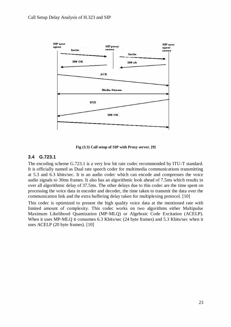
The diagram shown below represents the call setup made by SIP signalling protocol using a
proxy server. Here the call setup is handled by the proxy server as a representative between
the client and server. This proxy server takes care about the establishment and termination of
the call on the network between client and server. [9]
Call Setup Delay Analysis of H.323 and SIP
23
Fig (3.3) Call setup of SIP with Proxy server. [9]
3.4 G.723.1
The encoding scheme G.723.1 is a very low bit rate codec recommended by ITU-T standard.
It is officially named as Dual rate speech coder for multimedia communications transmitting
at 5.3 and 6.3 kbits/sec. It is an audio codec which can encode and compresses the voice
audio signals to 30ms frames. It also has an algorithmic look ahead of 7.5ms which results in
over all algorithmic delay of 37.5ms. The other delays due to this codec are the time spent on
processing the voice data in encoder and decoder, the time taken to transmit the data over the
communication link and the extra buffering delay taken for multiplexing protocol. [10]
This codec is optimized to present the high quality voice data at the mentioned rate with
limited amount of complexity. This codec works on two algorithms either Multipulse
Maximum Likelihood Quantization (MP-MLQ) or Algebraic Code Excitation (ACELP).
When it uses MP-MLQ it consumes 6.3 Kbits/sec (24 byte frames) and 5.3 Kbits/sec when it
uses ACELP (20 byte frames). [10]

4 NETWORK TOPOLOGY
In this section we going to describe the network topologies used to test the H.323 signaling
protocol and used to study the SIP signaling protocol. We also going to describe the process
performed in each topology.
4.1 Network Topology of H.323 Call Setup
Fig (4.1a) Real time topology for H.323
The figure (4.1a) shown above is the real time network topology built to analyze the call
setup for the signaling protocol H.323 in the Cisco lab. The devices we used to construct this
topology are H.323 soft phones, Cisco 2800 series routers, Cisco Pagent routers, Cisco
switches, PBX, traditional phones RJ11 and RJ45 cables to establish the connection.
The H.323 soft phones represent the end users which are connected to the switches over Vlan
10 and Vlan 20. The PC connected at Vlan 10 handles the data and the PC connected at Vlan
20 handles the voice. Their IP addresses are 192.168.3.0/24 and 192.168.7.0/24 respectively.
Then, to the same switch a router which is configured as Call Manager is connected over the
Vlan 50 with the IP address 192.168.50.0/24 and also another router which is configured as
the gateway and is connected over the Vlan 80. Then that router Gateway is connected to the
router Gatekeeper through the Internet cloud. The IP address for the Gateway and Gatekeeper
are 10.10.1.0/24 and 10.10.2.0/24 respectively. The destination soft phones are then
connected to the gatekeeper. The whole network capability is connected with 100 BaseT
Ethernet cables. EIGRP routing protocol is used to communicate with the whole network.
Here in this topology, we used a PBX which handles the traditional phones and this PBX is
connected to the Call Manager which is connected to the internet via the gateway. Now all
the 3 destinations are connected to each other. Calls can be generated from any source to
destinations.
To estimate the call setup time according to the real time process we built a traffic generator
in our topology and it is connected to the switch over Vlan 10 which can generate the traffic

Call Setup Delay Analysis of H.323 and SIP
25
from the PC which supports data. To simulate the call setup time at various conditions, traffic
is generated at different loads. One is at no load and the second one is at load 200 (medium)
and the third one is load 1000 (heavy). The bandwidth allotted to transmit all the packets
from traffic generator through this network topology is 32 Kbps.
To estimate the traffic and to calculate the call setup time, a free and open source network
analyzing software called Wireshark is used at both the local and foreign exchanges, because
it captures each and every actions performed in the topology like the REQ and ACK
messages passed to connect the call, packets transferred, the time taken to setup the
connection and the protocols used.
The Cisco IOS software for Gatekeeper and Traffic generator are installed in Cisco pagent
routers. The IOS for call manager and gateway are installed in Cisco 2800 series routers.
Wireshark is software which is installed in the workstation connected to the gateway and
gatekeeper.
Fig (4.1b) Logical structure of H.323 topology
= Hardware device
= Software installed on Hardware device
This logical diagram defines the process performed in the H.323 network topology. We
experimented our H.323 test environment according to the logical diagram shown above. We
fixed the phone numbers as 5556001 and 5559 for traditional phones connected to PBX.
Then the soft IP phone number fixed to the gateway is 5551 and the soft IP phone number
connected to the gatekeeper is 5552. To find out the call setup time of H.323 signaling
protocol we made calls between the traditional phones and the soft IP phones. In this H.323
test environment, RJ11 cable is used to connect the traditional phone to the PBX and RJ45
cables are used to connect the other devices in the network.
The calls made from each user passes through the gateway and gatekeeper. When the user in
N1 calls to the traditional phone, it takes messages to gatekeeper through gateway. Then it
communicates to the call manager (CM) to pass the voice packets to the traditional phone
connected to the PBX.
4.1.1 Call Flow Diagram of H.323
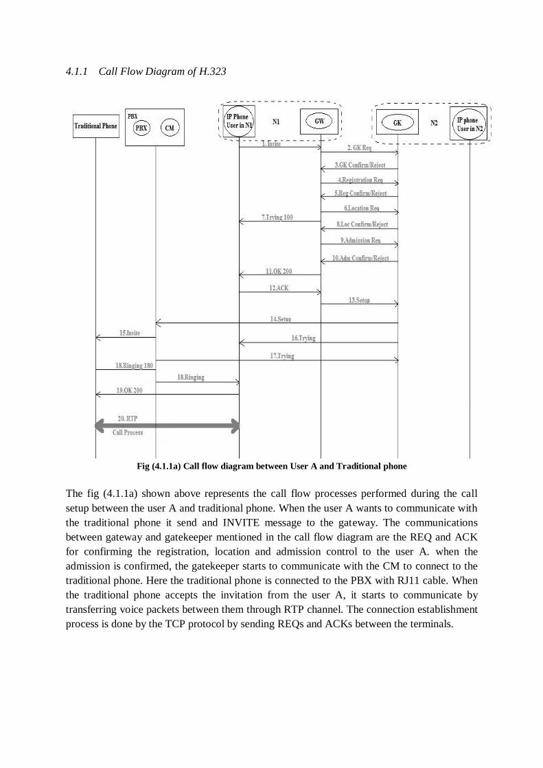
Fig (4.1.1a) Call flow diagram between User A and Traditional phone
The fig (4.1.1a) shown above represents the call flow processes performed during the call
setup between the user A and traditional phone. When the user A wants to communicate with
the traditional phone it send and INVITE message to the gateway. The communications
between gateway and gatekeeper mentioned in the call flow diagram are the REQ and ACK
for confirming the registration, location and admission control to the user A. when the
admission is confirmed, the gatekeeper starts to communicate with the CM to connect to the
traditional phone. Here the traditional phone is connected to the PBX with RJ11 cable. When
the traditional phone accepts the invitation from the user A, it starts to communicate by
transferring voice packets between them through RTP channel. The connection establishment
process is done by the TCP protocol by sending REQs and ACKs between the terminals.

Call Setup Delay Analysis of H.323 and SIP
27
Fig (4.1.1b) Call flow diagram between User B and Traditional phone
The fig (4.1.1b) shown above represents the call flow between the user B and the traditional
phone. The connection establishment process performed between user B and traditional
phone are same as like the process done between user A and traditional phone explained in
the section 4.1.1a.
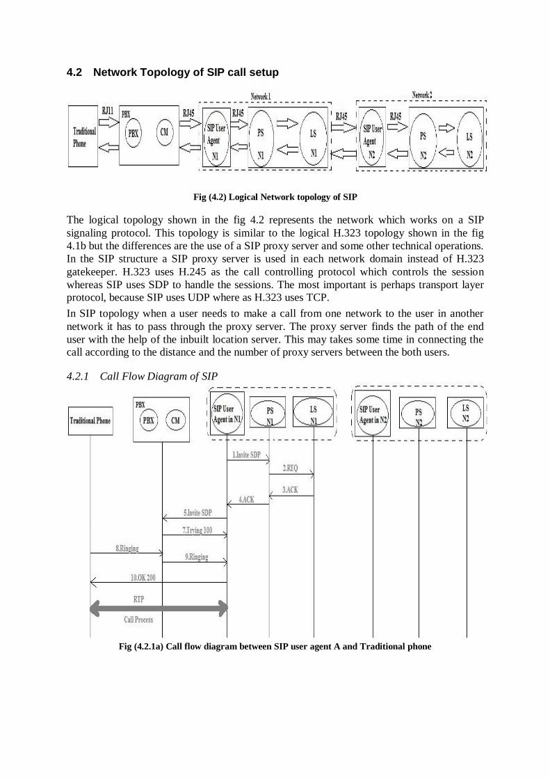
4.2 Network Topology of SIP call setup
Fig (4.2) Logical Network topology of SIP
The logical topology shown in the fig 4.2 represents the network which works on a SIP
signaling protocol. This topology is similar to the logical H.323 topology shown in the fig
4.1b but the differences are the use of a SIP proxy server and some other technical operations.
In the SIP structure a SIP proxy server is used in each network domain instead of H.323
gatekeeper. H.323 uses H.245 as the call controlling protocol which controls the session
whereas SIP uses SDP to handle the sessions. The most important is perhaps transport layer
protocol, because SIP uses UDP where as H.323 uses TCP.
In SIP topology when a user needs to make a call from one network to the user in another
network it has to pass through the proxy server. The proxy server finds the path of the end
user with the help of the inbuilt location server. This may takes some time in connecting the
call according to the distance and the number of proxy servers between the both users.
4.2.1 Call Flow Diagram of SIP
Fig (4.2.1a) Call flow diagram between SIP user agent A and Traditional phone

Call Setup Delay Analysis of H.323 and SIP
29
Fig (4.2.1b) Call flow diagram between SIP user agent B and traditional phone
The fig 4.2.1a and 4.2.1b shown above represent the connection establishment between the
SIP user agent A and traditional phone; and between the SIP user agent B and traditional
phone. The call connection process is done with the help of UDP protocol. When the user
agent A wants to communicate with the traditional phone, it passes the message through
proxy server. The proxy server gets the location of the destination from the location server
which is inbuilt with the proxy server. Every network domain has its own proxy server. When
the traditional phone accepts the invitation from the SIP user agent A, they start to
communicate with each other through the RTP channel.
Features in H.323 and SIP Topology
Features H.323 SIP
Gatekeeper Yes No
Proxy Server No Yes
UDP/IP Yes Yes
Session Description H.245 Yes No
Session Description SDP No Yes
EIGRP Yes Yes
Features in H.323 and SIP Topology
The table (4.2.1) shown above represents the features that are possible and available in both
the signaling protocols that are taken for analysis. The descriptions for each feature are
described in the previous section 3.
4.2.2 Session Description
H.245
For the session description, H.245 is used in H.323, where it can manage media
capabilities, establish and tear down media channels and also provide conference floor
control. A set of capability descriptors, listed in decreasing order of preference is used
to describe media capabilities in H.245. A capability descriptor is also known as
simultaneous capability set, which is a set of alternative capability sets. A list of
algorithms is available in each capability sets, from which one can be used at any
given time. These lists of algorithms help the terminals to support audio, video and
data simultaneously. [8]
SDP
SIP uses SDP for session description process. It holds a list of media types and the
supported encoding schemes for each. The cross media and inter media are not
expressed by SDP, like in H.245. SDP also cannot express that in conjunction with
certain video codecs, certain audio codecs to be used. Most of the media capabilities
in SIP can be described by H.245 but it is hard for SIP to describe the capabilities
handled by H.245. Using the „multipart‟ content type many SDP messages can be
carried in the message body of SIP INVITE requests and responses. [8]
4.3 Transmission Control Protocol (TCP)
Transmission control protocol (TCP) was developed in 1984 and it is defined by RFC-793.
TCP is the most mature protocol, which is considered to be more familiar in use across the
internet world for data transmission. TCP is a connection oriented protocol which sends REQ
and receives ACK between the end users to establish a connection. The connection with TCP
is more reliable because of the functionality in arranging the data packets to be transmitted in
the same fixed sizes and providing a sequence number to each packet before transmitting
them over the internet. Because of this sequence number, the data packets are sent in a
particular to the destination. [2]
If any data packet is lost while transmitting, immediately the destination will send a
retransmission request to the source to resend that particular lost data. The destination can
easily identify the lost data with the help of the sequence number attached to each packet.
Hence because of this process TCP provides a reliable form of data transmission which is
essential amongst internet users. [2]
In VoIP technology, TCP can play its role only up to the call setup process between the end
users. Once the call is established, it automatically adopts the RTP protocol transmission
running over UDP which can handle voice packets, because TCP cannot transfer voice
packets along with the data packets. The other major features of TCP are error detection,
congestion control, flow control and reliability. [2]
4.4 User Datagram Protocol (UDP)
UDP is a transport layer protocol defined to use with the IP network layer protocol. It is
defined by RFC 768. To the end system, UDP provides a best effort datagram service. It is
an unreliable service, it provides no guarantees for data delivery and the duplication is not
protected. UDP and the UDP-Lite variant are similar when compared with other protocols in
connecting the end systems. The end to end connection between communicating end systems
are not established before by them. [2]
UDP is popular because of tunnelling protocol, where the packets of another protocol are
encapsulated inside UDP datagram from one tunnelling endpoint and then they are
Call Setup Delay Analysis of H.323 and SIP
31
transmitted to another tunnelling endpoint these UDP datagrams are then expanded and
forwarded as original packets. The tunnelling service in UDP helps in establishing virtual
links that directly connect to distant locations in the physical network. UDP provides no
communication security over the network. To create protection for the packets from
eavesdropping, tampering, or message forgery additional protocol mechanism which provides
security services should be configured in the network. [2]
4.5 REAL-TIME TRANSPORT PROTOCOL (RTP)
Real-Time Transport Protocol (RTP) is developed by IETF and established in 1996.It
provides the transport of real-time data packets. RTP allows the protocol to easily adapt new
versions of audio and video.
RTP allows end-to-end transport services in order to transmit the real-time data. These
services include the features given below
1. payload type identification
2. sequence numbers
3. Time stamps
RTP and RTCP both can be used together in conjunction. RTP carries media such as video
and audio, whereas RTCP is used to monitor transmission statistics and also provide (QOS)
information. RTP is used for transfer of multimedia data on the other hand RTCP control
information and QOS parameters. [6]
The major drawback of UDP is when the receiver receives the packets from sender they are
mostly unsynchronized and unordered. Because UDP does not provide the services like
sequence number and time stamps. Hence to synchronize and reorder the packets in UDP the
RTP service is very much important. These protocols are configured to our topology for our
expected results and analysis. [2]

5 RESULTS
5.1 Call Setup Results on H.323
In the Cisco lab, with the help of Cisco routers and switches, the real time network topology as shown
in fig 4.1 was built to analyse the call setup using H.323 signaling protocol. The signals which passed
through this network are encoded by G.711 encoding scheme. The run time analyses chart created by
Wireshark network analyser shown in fig 5.1 represents the successful connectivity of the network.
From this chart, before the data is being transferred, the devices and the protocols in the network are
announcing themselves that they are active to transmit the signals across the network. Here the
messages like „Hello‟ and „Keep Alive‟ of EIGRP, TCP, Skinny and SCCP are passed between the
endpoints to mention that they are active. So the fig 5.1 shows that the network topology in fig 4.1 is
successfully built and it is in running state.
Fig (5.1) Active functions of H.323 network topology
5.2 Traffic Generated
In order to analyse the network topology on a real time status, a traffic generator is used to
generate the traffic of various types over the network. The traffic generator is linked with the
data computer through a switch over Vlan 10. Hence it can generate traffic from the computer
connected to Vlan 10. The figure 5.2 shown below clearly mentions all kinds of traffics like
Call Setup Delay Analysis of H.323 and SIP
33
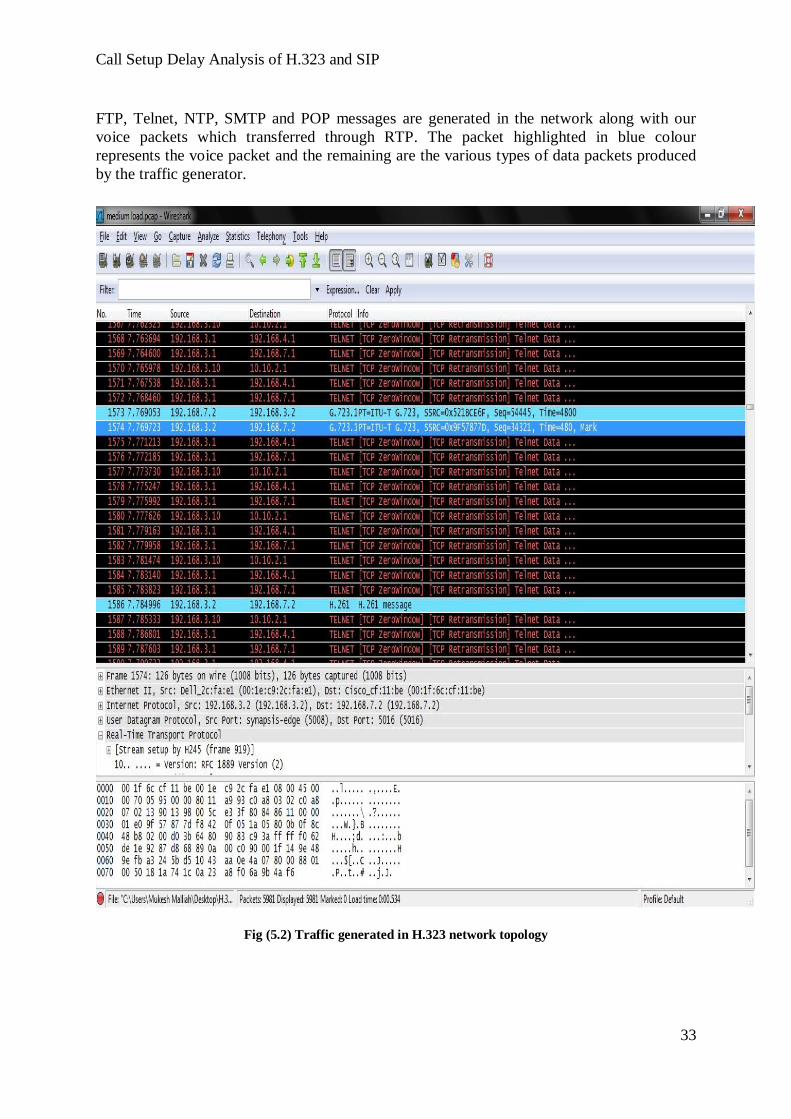
FTP, Telnet, NTP, SMTP and POP messages are generated in the network along with our
voice packets which transferred through RTP. The packet highlighted in blue colour
represents the voice packet and the remaining are the various types of data packets produced
by the traffic generator.
Fig (5.2) Traffic generated in H.323 network topology

5.3 Call setup at various loads
5.3.1 No Load
The first experiment in this call setup delay analyses is performed under ZERO load. In this process
only the voice packets were transmitted through the network and the traffic generator was kept OFF.
The voice packets were transmitted between the Cisco IP soft phone and the traditional phone
connected to the PBX. To setup a call between these two terminals it took almost 177 milliseconds.
We declare this time from the average obtained by establishing a number of calls under the same
condition. The fig 5.3.1 is an example to show the experiment and highlighted circle defines the call
setup time. In that mean time, the H.323 phone and traditional phones are in the process of
establishing the call by sending TCP and H.323 messages.
Here the messages transferred to connect the call are, Call State Message, Call Info Message,
Gatekeeper registration, Gatekeeper admission, Gatekeeper location, Open Receive Channel, Open
Receive channel Acknowledgement and Start Media Transmission are the messages transferred by
H.323 and REQ and ACK are done by TCP to setup the calls.
Tab (5.3.1) Call Setup delay of H.323 at no load
Arithmetic mean A = ∑ (call setup delay)/N
= (173+176+194+171+186+167+169+185+171+175)/10
A =177 ms
Standard Deviation S = √ ((call setup delay- Arithmetic Mean) ^2)/N
S = √ (16+1+289+36+81+100+64+64+36+4)/10
= √691/10
S = 8 ms
Call No Calls Made Between Process Time in Chart Call setup delay (ms)
Call 1 5551-5559 16.264-16.437 173
Call 2 5551-5556001 17.748-17.924 176
Call 3 5559-5551 15.257-15.531 194
Call 4 5556001-5551 16.203-16.374 171
Call 5 5552-5556001 15.881-16.067 186
Call 6 5552-5559 16.786-16.953 167
Call 7 5559-5552 15.632-15.801 169
Call 8 5556001-5552 16.849-17.034 185
Call 9 5551-5556001 15.187-15.358 171
Call 10 5552-5559 16.503-16.678 175
Arithmetic Mean = 177ms
Standard Deviation = 8ms

Call Setup Delay Analysis of H.323 and SIP
35
Fig (5.3.1) Call Setup delay of H.323 at no load
5.3.2 Medium Load
The fig 5.3.2a and 5.3.2b shown below represents the second experiment and which was
undertaken under a medium load. In order to do the traffic generator was kept ON and it was
assigned to a load of 200. Before setting up the call between the terminals the traffic
generator was started first and then the call has been made to analyze the call setup time
under this medium load. Call setup time is estimated by connecting a number of calls under
the same condition and the mean time in setting the call is estimated around 253 milliseconds.
The fig 5.3.2a shows the initiation of the call setup time and it is highlighted at 7.011th
second. And the fig 5.3.2c shows the end of the call setup process and is noted at 7.221th
second. The time interval of this process takes almost 210 milliseconds. The call mentioned
in the figure is an example to explain the process among the number of calls made to estimate
call setup time.
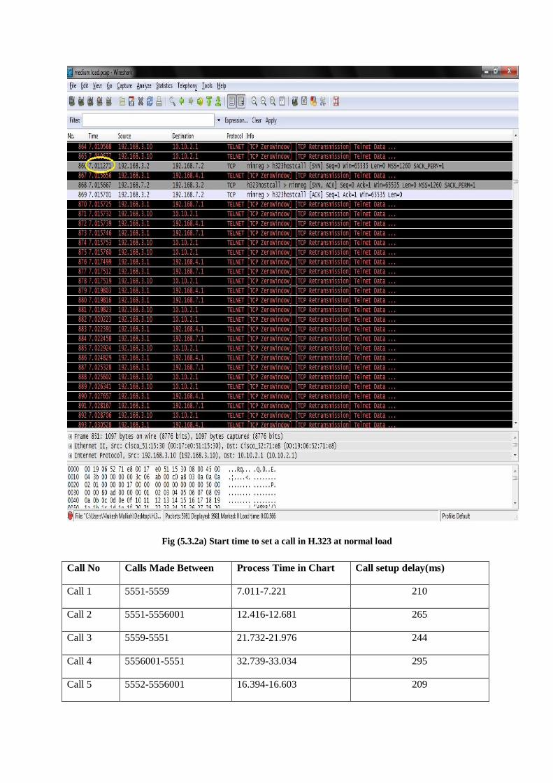
Fig (5.3.2a) Start time to set a call in H.323 at normal load
Call No Calls Made Between Process Time in Chart Call setup delay(ms)
Call 1 5551-5559 7.011-7.221 210
Call 2 5551-5556001 12.416-12.681 265
Call 3 5559-5551 21.732-21.976 244
Call 4 5556001-5551 32.739-33.034 295
Call 5 5552-5556001 16.394-16.603 209

Call Setup Delay Analysis of H.323 and SIP
37
Call 6 5552-5559 23.487-23.751 264
Call 7 5559-5552 20.043-20.311 268
Call 8 5556001-5552 21.300-21.561 261
Call 9 5551-5556001 16.049-16.294 245
Call 10 5552-5559 22.602-22.873 271
Arithmetic Mean = 253 ms
Standard Deviation = 26 ms
Tab (5.3.2) Call Setup delays of H.323 at medium loads
Fig (5.3.2b) Call connecting process of H.323 at normal load

Fig (5.3.2c) Call connected time of H.323 at normal load
Arithmetic mean A = ∑ (call setup delay)/N
A = 253ms
Standard Deviation S = √ ((call setup delay- Arithmetic Mean) ^2)/N
S = 26 ms
Call Setup Delay Analysis of H.323 and SIP
39
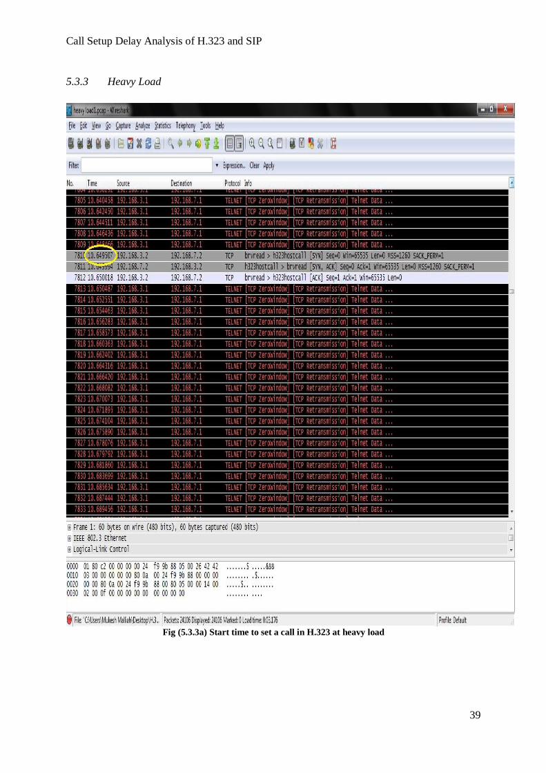
5.3.3 Heavy Load
Fig (5.3.3a) Start time to set a call in H.323 at heavy load

Fig (5.3.3b) Call connecting process of H.323 at heavy load

Call Setup Delay Analysis of H.323 and SIP
41
Fig (5.3.3c) Call connected time of H.323 at heavy load
The final step to analyze the call setup time is also performed by making number of calls
under a heavy load of traffic and from the average of call setup time of each call; the call
setup delay is estimated as 360 milliseconds. Here the traffic generator was set to 1000 under
the same bandwidth and then the call setup was executed. The fig 5.3.3a, 5.3.3b and 5.3.3c
are the examples of the call setup process made under heavy traffic and the call initiation time
here is noted at 10.649th second and from the fig 5.3.3c, the time for the final step of the call
setup is noted as 10.911th second. From the results of one of the calls, the time interval
between them to setup a call is almost 262 milliseconds under a heavy traffic network.

Call No Calls Made Between Process Time in Chart Call setup delay(ms)
Call 1 5551-5556001 10.649-10.911 262
Call 2 5551-5559 14.346-14.687 341
Call 3 5559-5551 16.060-16.359 299
Call 4 5556001-5551 28.301-28.698 397
Call 5 5552-5556001 17.918-18.327 409
Call 6 5552-5559 23.266-23.654 388
Call 7 5559-5552 19.459-19.876 417
Call 8 5556001-5552 23.919-24.211 292
Call 9 5551-5556001 21.194-21.587 393
Call 10 5552-5559 16.994-17.398 404
Arithmetic Mean = 360 ms
Standard Deviation = 54ms
Tab (5.3.3) Call Setup delays of H.323 at heavy loads
Arithmetic mean A = ∑ (call setup delay)/N
A = 360 ms
Standard Deviation S = √ ((call setup delay- Arithmetic Mean) ^2)/N
S = 54 ms
Call Setup Delay Analysis of H.323 and SIP
43
5.4 Call Setup Delay results on SIP
The call setup results of H.323 are done experimentally. The SIP call setup results are derived
theoretically.
The difference between a H.323 using network and the SIP using network is the Server and the
transport protocol. Here in H.323, as mentioned earlier in section 4, it uses a Gatekeeper and TCP as
the call setup protocol and in SIP it uses a Proxy Server instead of Gatekeeper and UDP as call setup
protocol.
From the paper published in Columbia University with University of Wollongong, Australia and also
from the paper completed by 3Com Corporation and Cisco Systems, it is find out that the time taken
to setup a call using SIP between IP telephony and a PSTN is less than the time taken by H.323. In
their experiment, they analyzed the call setup time of SIP signaling protocol on a real time network.
They connected the calls between three various cities of USA at various networks with the help of
proxy servers at the peak time. Then they measured the call setup time by measuring the time taken to
reach each proxy servers between the end users. Then they find out the call setup time of SIP
signaling protocol by calculating the time taken at each hops.
The SIP call setup delay is declared as 2~3 round trip time (one RTT approx to 90 to 100
milliseconds). It was also done on various scenarios like on various loads and various distances. [11]
[12]

6 CONCLUSION
In our thesis, we experimentally analysed the call setup delay for H.323. Using the existing
materials, we surveyed the call setup delay for SIP literally. We obtained an average call
setup delay for H.323, at a peak time (heavy traffic) of almost 300~400 milliseconds and for
SIP we studied this call setup delay as 200~300 milliseconds. The call setup time of H.323
signalling protocol is thus a little higher than the call setup time of H.323 signaling protocol.
It is probably because of the Cisco devices we used for our experiments. The call setup time
in traditional telephony is 4 minutes in 1923, it is reduced slowly and finally with the help of
IP telephony the call setup time is reduced to 200~400 milliseconds in the current decade.
In our thesis we clearly studied and found that the call setup delay of SIP is a little less than
H.323 but when we consider the other services of both the signaling protocols; we can say
that H.323 is better than SIP. As the call setup performed in H.323 is done with the help of
TCP, the connection is more reliable. However in SIP, the call setup is unreliable because of
UDP. More-over the most important factor of H.323 is that, along with the audio packets it
can transmit video and data packets with more reliability than SIP. Also, H.323 is more
compatible; it can adopt any versions according to the users‟ necessity. When considering the
bandwidth utilization, H.323 requires less bandwidth because it transmits the packets in
binary format and in SIP it transfer in text format which requires more bandwidth than H.323.
Even SIP has its own features like less call setup delay and flexibility as their advantages; the
reliability, compatibility and bandwidth utilization of H.323 should also be taken into account
as their advantages which are more essential.
Hence because of this, most of the organisations use H.323 even though they are expensive
when compared to SIP.

Call Setup Delay Analysis of H.323 and SIP
45
7 References
[1] Steve Shergold, Internet Telephony: An Introduction, Article: Compliance
Engineering, http://www.ce-mag.com/archive/1999/marchapril/Shergold.html
[2] Jonathan Davidson, James Peters, Manoj Bhatia, Satish Kalidindi, Voice over IP
Fundamentals, Second Edition, Cisco Press, ISBN1-58705-257-1, July 27,2006.
[3] Jonathan Davidson, Tina Fox, Deploying Cisco Voice over IP Solutions, Cisco Press.
[4] Ian J. Brown, Kevin Dooley, ”Cisco Cookbook”, O‟Reilly Publisher, 2003, ISBN0-
596-00367-6
[5] Understanding from Packetizer, H.323 Versus SIP: A Comparison,
http://www.packetizer.com/ipmc/h323_vs_sip/
[6] Dr. Wei Liu, Carolyn Matthews, Lydia Parziale, TCP/IP Tutorial and Technical
Overview, Red Books, ISBN: 0738494682, 19 Dec 2006.
[7] Understanding from Voice over IP: Protocols and Standards, Rakesh Arora,
http://www.cse.wustl.edu/~jain/cis788-99/ftp/voip_protocols/index.html#intro
[8] Mapping VoIP Components and Protocols to the OSI Model OSI Layer, Article: All
Network and Cisco Articles, July 17, 2008, http://www.ciscoarticles.com/Voice-Over-
IP/703.html
[9] Ross Carter, Microsoft Real time Communications: Protocols and Technologies, July
03, 2003. http://technet.microsoft.com/en-us/library/bb457036.aspx
[10] Understanding from ITU G.723.1 article. http://www.itu.int/rec/T-REC-G.723.1-
200605-I/en
[11] T. Eyers and H. Schulzrinne, “Predicting Internet telephony call setup delay”, Proc. IP
Telephony Workshop, pp. 2000.
[12] Ismail Dalgic and Hanlin Fang, "Comparison of H.323 and SIP for IP Telephony
Signaling," in Proc. of Photonics East, Boston, Massachusetts, Sep. 1999.
[13] International Telecommunication Union, “Network grade of service parameters and
target values for circuit-switched services in the evolving isdn,” Recommendation
E.721, Telecommunication Standardization Sector of ITU, Geneva, Switzerland, May
1999.


Call Setup Delay Analysis of H.323 and SIP
47
Appendix A:
Call Manager Configuration
Building configuration...
Current configuration : 2802 bytes
!
version 12.4
service timestamps debug datetime msec
service timestamps log datetime msec
no service password-encryption
!
hostname CME
!
boot-start-marker
boot-end-marker
!
!
no aaa new-model
memory-size iomem 10
dot11 syslog
!
!
ip cef
no ip dhcp use vrf connected
!
ip dhcp pool ITS
network 192.58.7.0 255.255.255.0
option 150 ip 192.58.7.1
default-router 192.58.7.1
!
multilink bundle-name authenticated
!
voice-card 0
no dspfarm
!
archive
log config
hidekeys
!

interface Loopback58
ip address 192.58.7.1 255.255.255.0
!
interface FastEthernet0/0
bandwidth 64
no ip address
shutdown
duplex auto
speed auto
!
interface FastEthernet0/1
ip address 192.168.50.2 255.255.255.0
duplex auto
speed auto
!
router eigrp 100
network 10.0.0.0
network 192.0.0.0 0.255.255.255
no auto-summary
!
ip forward-protocol nd
!
ip http server
no ip http secure-server
!
tftp-server flash:p
tftp-server flash:P00307020200.bin
tftp-server flash:P00307020200.loads
tftp-server flash:P00307020200.sb2
tftp-server flash:P00307020200.sbn
tftp-server flash:P00403020214.bin
!
control-plane
!
voice-port 0/2/0
signal groundStart
cptone SE
impedance complex2
music-threshold -70
caller-id enable
!

Call Setup Delay Analysis of H.323 and SIP
49
voice-port 0/2/1
signal groundStart
cptone SE
impedance complex2
music-threshold -70
!
dial-peer voice 1 pots
destination-pattern 5556001
port 0/2/0
forward-digits all
!
dial-peer voice 2 pots
destination-pattern 5559
port 0/2/1
forward-digits all
!
gateway
timer receive-rtp 1200
!
telephony-service
load 7910 P00403020214
load 7960-7940 P00307020200
max-ephones 6
max-dn 6
ip source-address 192.58.7.1 port 2000
auto assign 1 to 6
dialplan-pattern 1 5... extension-length 4
voicemail 5
max-conferences 8 gain -6
transfer-system full-consult
!
ephone-dn 1 dual-line
number 5551
call-forward busy 5
call-forward noan 5 timeout 18
!
ephone-dn 2 dual-line
number 5552
call-forward busy 5
call-forward noan 5 timeout 18
!
ephone-dn 3 dual-line
number 5553
call-forward busy 5
call-forward noan 5 timeout 18
!
ephone-dn 4 dual-line
number 5554
call-forward busy 5
call-forward noan 5 timeout 18
!
ephone-dn 5 dual-line
number 5555
call-forward busy 5
call-forward noan 5 timeout 18
!
ephone-dn 6 dual-line
number 5556
call-forward busy 5
call-forward noan 5 timeout 18
!
ephone 1
no multicast-moh
mac-address 0018.8B84.BE84
type CIPC
button 1:1
!
ephone 2
no multicast-moh
mac-address 0018.8B83.3CBC
type CIPC
button 1:2
!
ephone 3
no multicast-moh
!
ephone 4
no multicast-moh
!
ephone 5
no multicast-moh

Call Setup Delay Analysis of H.323 and SIP
51
!
ephone 6
no multicast-moh
!
line con 0
line aux 0
line vty 0 4
login
!
scheduler allocate 20000 1000
!
end
IP Interface Brief:
Interface IP-Address OK? Method Status Protocol
FastEthernet0/0 unassigned YES manual administratively down down
FastEthernet0/1 192.168.50.2 YES manual up up
Loopback58 192.58.7.1 YES manual up up
IP Routing:
Codes: C - connected, S - static, R - RIP, M - mobile, B - BGP
D - EIGRP, EX - EIGRP external, O - OSPF, IA - OSPF inter area
N1 - OSPF NSSA external type 1, N2 - OSPF NSSA external type 2
E1 - OSPF external type 1, E2 - OSPF external type 2
i - IS-IS, su - IS-IS summary, L1 - IS-IS level-1, L2 - IS-IS level-2
ia - IS-IS inter area, * - candidate default, U - per-user static route
o - ODR, P - periodic downloaded static route
Gateway of last resort is not set
D 192.168.14.0/24 [90/30720] via 192.168.50.1, 02:19:38, FastEthernet0/1
D 192.168.4.0/24 [90/35840] via 192.168.50.1, 01:14:01, FastEthernet0/1
10.0.0.0/24 is subnetted, 2 subnets
D 10.10.1.0 [90/30720] via 192.168.50.1, 02:19:38, FastEthernet0/1
D 10.10.2.0 [90/33280] via 192.168.50.1, 02:19:38, FastEthernet0/1
C 192.58.7.0/24 is directly connected, Loopback58
D 192.168.7.0/24 [90/30720] via 192.168.50.1, 02:19:38, FastEthernet0/1
C 192.168.50.0/24 is directly connected, FastEthernet0/1
D 192.168.3.0/24 [90/30720] via 192.168.50.1, 02:19:39, FastEthernet0/1
Appendix B Gateway Configuration
Building configuration...
Current configuration : 2127 bytes
!
version 12.4
service timestamps debug datetime msec
service timestamps log datetime msec
no service password-encryption
!
hostname GW
!
boot-start-marker
boot-end-marker
!
no aaa new-model
memory-size iomem 5
dot11 syslog
ip cef
!
no ip dhcp use vrf connected
!
ip dhcp pool its
network 192.168.7.0 255.255.255.0
option 150 ip 192.168.7.1
default-router 192.168.7.1
!
multilink bundle-name authenticated
!
voice-card 0
codec complexity high
!
archive
log config
Call Setup Delay Analysis of H.323 and SIP
53
hidekeys
!
interface FastEthernet0/0
no ip address
duplex auto
speed auto
!
interface FastEthernet0/0.3
encapsulation dot1Q 10
ip address 192.168.3.1 255.255.255.0
!
interface FastEthernet0/0.7
encapsulation dot1Q 20
ip address 192.168.7.1 255.255.255.0
h323-gateway voip interface
h323-gateway voip id gk1.gw1.com ipaddr 10.10.2.1 1719
h323-gateway voip h323-id gw1
!
interface FastEthernet0/0.13
encapsulation dot1Q 13
ip address 192.168.14.1 255.255.255.0
!
interface FastEthernet0/0.50
encapsulation dot1Q 50
ip address 192.168.50.1 255.255.255.0
!
interface FastEthernet0/1
ip address 10.10.1.1 255.255.255.0
duplex auto
speed auto
!
interface Serial0/1/0
no ip address
shutdown
no fair-queue
clock rate 125000
!
interface Serial0/1/1
no ip address
shutdown
!
router eigrp 100
network 10.0.0.0
network 192.168.0.0 0.0.255.255
no auto-summary
!
ip forward-protocol nd
!
ip http server
no ip http secure-server
!
tftp-server flash:P00307020200.bin
tftp-server flash:P00307020200.loads
tftp-server flash:P00307020200.sb2
tftp-server flash:P00307020200.sbn
!
control-plane
!
dial-peer voice 1 pots
destination-pattern 5556
forward-digits all
!
dial-peer voice 3 pots
destination-pattern 5556003
forward-digits all
!
dial-peer voice 2 pots
destination-pattern 5559
forward-digits all
no register e164
!
dial-peer voice 5 pots
destination-pattern 5......
forward-digits all
!
dial-peer search type voice data
gateway
timer receive-rtp 1200
!
line con 0
line aux 0
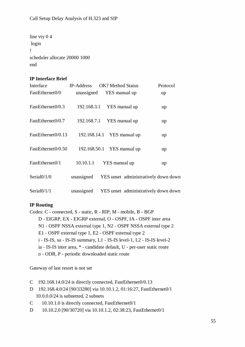
Call Setup Delay Analysis of H.323 and SIP
55
line vty 0 4
login
!
scheduler allocate 20000 1000
end
IP Interface Brief
Interface IP-Address OK? Method Status Protocol
FastEthernet0/0 unassigned YES manual up up
FastEthernet0/0.3 192.168.3.1 YES manual up up
FastEthernet0/0.7 192.168.7.1 YES manual up up
FastEthernet0/0.13 192.168.14.1 YES manual up up
FastEthernet0/0.50 192.168.50.1 YES manual up up
FastEthernet0/1 10.10.1.1 YES manual up up
Serial0/1/0 unassigned YES unset administratively down down
Serial0/1/1 unassigned YES unset administratively down down
IP Routing
Codes: C - connected, S - static, R - RIP, M - mobile, B - BGP
D - EIGRP, EX - EIGRP external, O - OSPF, IA - OSPF inter area
N1 - OSPF NSSA external type 1, N2 - OSPF NSSA external type 2
E1 - OSPF external type 1, E2 - OSPF external type 2
i - IS-IS, su - IS-IS summary, L1 - IS-IS level-1, L2 - IS-IS level-2
ia - IS-IS inter area, * - candidate default, U - per-user static route
o - ODR, P - periodic downloaded static route
Gateway of last resort is not set
C 192.168.14.0/24 is directly connected, FastEthernet0/0.13
D 192.168.4.0/24 [90/33280] via 10.10.1.2, 01:16:27, FastEthernet0/1
10.0.0.0/24 is subnetted, 2 subnets
C 10.10.1.0 is directly connected, FastEthernet0/1
D 10.10.2.0 [90/30720] via 10.10.1.2, 02:38:23, FastEthernet0/1

D 192.58.7.0/24 [90/156160] via 192.168.50.2, 02:22:05, FastEthernet0/0.50
C 192.168.7.0/24 is directly connected, FastEthernet0/0.7
C 192.168.50.0/24 is directly connected, FastEthernet0/0.50
C 192.168.3.0/24 is directly connected, FastEthernet0/0.3
Appendix C Gatekeeper Configuration
Building configuration...
Current configuration : 1727 bytes
!
version 12.4
service timestamps debug datetime msec
service timestamps log datetime msec
no service password-encryption
!
hostname GK
!
boot-start-marker
boot-end-marker
!
logging message-counter syslog
!
no aaa new-model
memory-size iomem 10
!
dot11 syslog
ip source-route
!
ip cef
!
ip dhcp pool GK-Client
network 192.168.4.0 255.255.255.0
default-router 192.168.4.1
!
no ipv6 cef
!
multilink bundle-name authenticated
!
voice-card 0
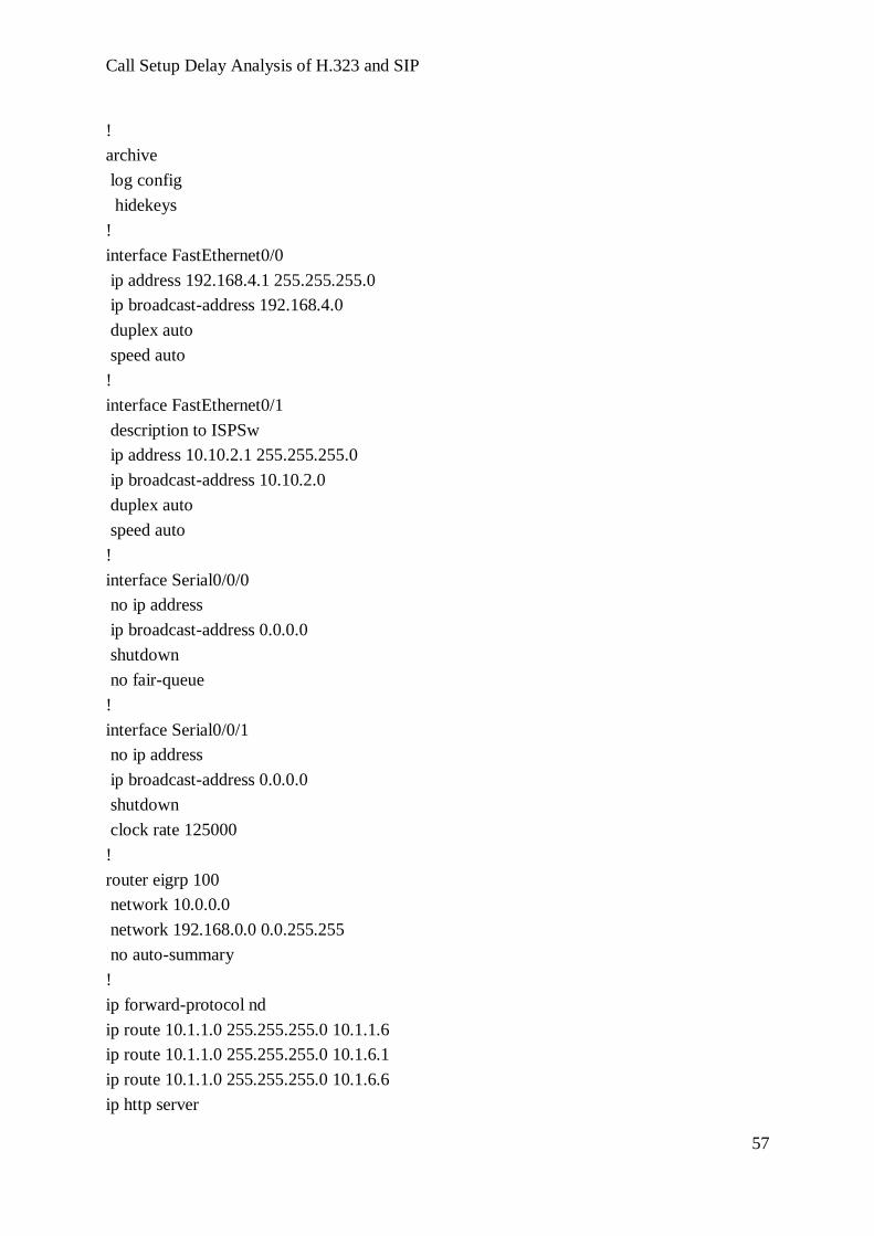
Call Setup Delay Analysis of H.323 and SIP
57
!
archive
log config
hidekeys
!
interface FastEthernet0/0
ip address 192.168.4.1 255.255.255.0
ip broadcast-address 192.168.4.0
duplex auto
speed auto
!
interface FastEthernet0/1
description to ISPSw
ip address 10.10.2.1 255.255.255.0
ip broadcast-address 10.10.2.0
duplex auto
speed auto
!
interface Serial0/0/0
no ip address
ip broadcast-address 0.0.0.0
shutdown
no fair-queue
!
interface Serial0/0/1
no ip address
ip broadcast-address 0.0.0.0
shutdown
clock rate 125000
!
router eigrp 100
network 10.0.0.0
network 192.168.0.0 0.0.255.255
no auto-summary
!
ip forward-protocol nd
ip route 10.1.1.0 255.255.255.0 10.1.1.6
ip route 10.1.1.0 255.255.255.0 10.1.6.1
ip route 10.1.1.0 255.255.255.0 10.1.6.6
ip http server

no ip http secure-server
!
nls resp-timeout 1
cpd cr-id 1
!
control-plane
!
ccm-manager fax protocol cisco
!
gatekeeper
zone local gk1.gw1.com gw1.com 10.10.2.1
zone local gk1.w1.com gw1.com
zone remote gk2.gw2.com gw2.com 10.10.7.1 1719
zone prefix gk1.gw1.com 17..
zone prefix gk1.gw1.com 50..
gw-type-prefix 1#* default-technology
no shutdown
!
line con 0
line aux 0
line vty 0 4
login
!
scheduler allocate 20000 1000
end
IP Routing
Codes: C - connected, S - static, R - RIP, M - mobile, B - BGP
D - EIGRP, EX - EIGRP external, O - OSPF, IA - OSPF inter area
N1 - OSPF NSSA external type 1, N2 - OSPF NSSA external type 2
E1 - OSPF external type 1, E2 - OSPF external type 2
i - IS-IS, su - IS-IS summary, L1 - IS-IS level-1, L2 - IS-IS level-2
ia - IS-IS inter area, * - candidate default, U - per-user static route
o - ODR, P - periodic downloaded static route
Gateway of last resort is not set
D 192.168.14.0/24 [90/33280] via 10.10.2.2, 02:41:07, FastEthernet0/1
C 192.168.4.0/24 is directly connected, FastEthernet0/0
10.0.0.0/24 is subnetted, 2 subnets
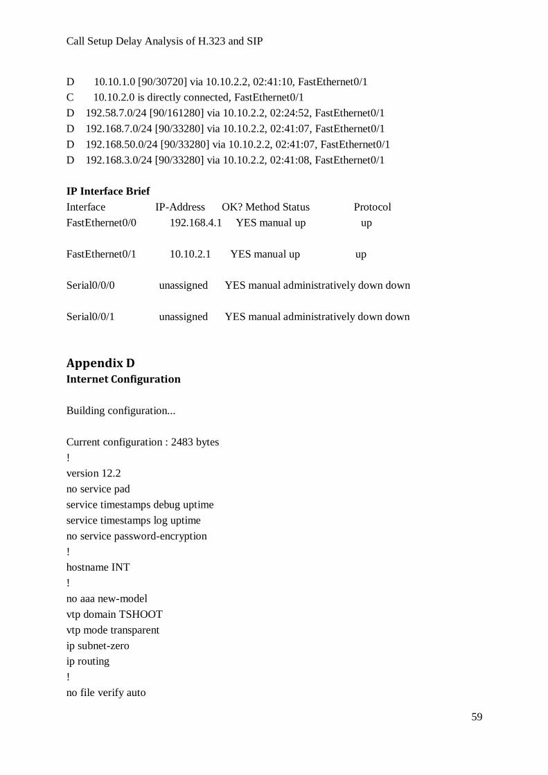
Call Setup Delay Analysis of H.323 and SIP
59
D 10.10.1.0 [90/30720] via 10.10.2.2, 02:41:10, FastEthernet0/1
C 10.10.2.0 is directly connected, FastEthernet0/1
D 192.58.7.0/24 [90/161280] via 10.10.2.2, 02:24:52, FastEthernet0/1
D 192.168.7.0/24 [90/33280] via 10.10.2.2, 02:41:07, FastEthernet0/1
D 192.168.50.0/24 [90/33280] via 10.10.2.2, 02:41:07, FastEthernet0/1
D 192.168.3.0/24 [90/33280] via 10.10.2.2, 02:41:08, FastEthernet0/1
IP Interface Brief
Interface IP-Address OK? Method Status Protocol
FastEthernet0/0 192.168.4.1 YES manual up up
FastEthernet0/1 10.10.2.1 YES manual up up
Serial0/0/0 unassigned YES manual administratively down down
Serial0/0/1 unassigned YES manual administratively down down
Appendix D Internet Configuration
Building configuration...
Current configuration : 2483 bytes
!
version 12.2
no service pad
service timestamps debug uptime
service timestamps log uptime
no service password-encryption
!
hostname INT
!
no aaa new-model
vtp domain TSHOOT
vtp mode transparent
ip subnet-zero
ip routing
!
no file verify auto

spanning-tree mode pvst
spanning-tree extend system-id
!
vlan internal allocation policy ascending
!
vlan 10
name Data
!
vlan 20
name Voice
!
vlan 30
name GW1
!
vlan 40
name GK1
!
vlan 70
name Monitoring
!
interface FastEthernet0/1
switchport access vlan 30
switchport trunk encapsulation dot1q
switchport mode access
!
interface FastEthernet0/2
switchport access vlan 40
switchport trunk encapsulation dot1q
switchport mode access
!
interface FastEthernet0/3
switchport access vlan 50
switchport trunk encapsulation dot1q
switchport mode access
!
interface FastEthernet0/4
switchport access vlan 60
switchport trunk encapsulation dot1q
switchport mode access
!
interface FastEthernet0/5

Call Setup Delay Analysis of H.323 and SIP
61
no switchport
no ip address
!
interface FastEthernet0/6
switchport mode access
!
interface FastEthernet0/7
no switchport
ip address 10.10.1.2 255.255.255.0
!
interface FastEthernet0/8
no switchport
ip address 10.10.2.2 255.255.255.0
!
interface FastEthernet0/9
switchport mode access
!
interface FastEthernet0/10
switchport mode access
!
interface FastEthernet0/11
switchport mode access
!
interface FastEthernet0/12
switchport mode access
!
interface FastEthernet0/13
switchport access vlan 70
switchport mode access
!
interface FastEthernet0/14
!
interface FastEthernet0/15
!
interface FastEthernet0/16
!
interface FastEthernet0/17
!
interface FastEthernet0/18
!
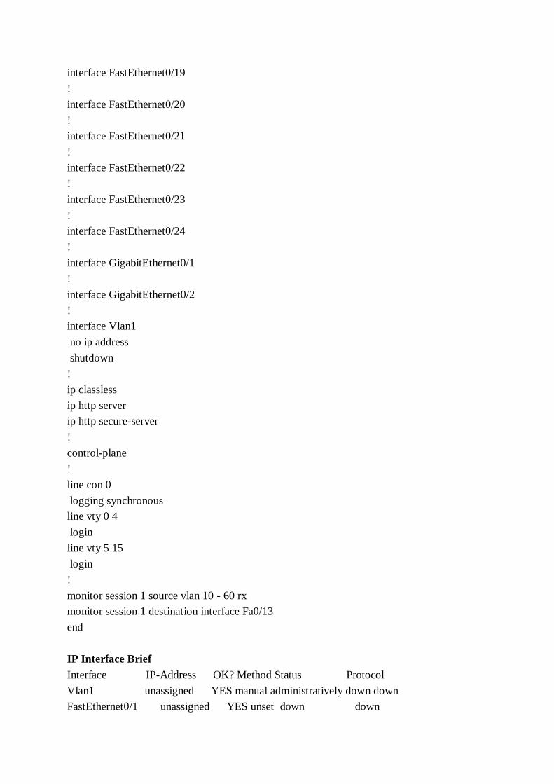
interface FastEthernet0/19
!
interface FastEthernet0/20
!
interface FastEthernet0/21
!
interface FastEthernet0/22
!
interface FastEthernet0/23
!
interface FastEthernet0/24
!
interface GigabitEthernet0/1
!
interface GigabitEthernet0/2
!
interface Vlan1
no ip address
shutdown
!
ip classless
ip http server
ip http secure-server
!
control-plane
!
line con 0
logging synchronous
line vty 0 4
login
line vty 5 15
login
!
monitor session 1 source vlan 10 - 60 rx
monitor session 1 destination interface Fa0/13
end
IP Interface Brief
Interface IP-Address OK? Method Status Protocol
Vlan1 unassigned YES manual administratively down down
FastEthernet0/1 unassigned YES unset down down

Call Setup Delay Analysis of H.323 and SIP
63
FastEthernet0/2 unassigned YES unset down down
FastEthernet0/3 unassigned YES unset down down
FastEthernet0/4 unassigned YES unset down down
FastEthernet0/5 unassigned YES manual down down
FastEthernet0/6 unassigned YES unset down down
FastEthernet0/7 10.10.1.2 YES manual up up
FastEthernet0/8 10.10.2.2 YES manual up up
FastEthernet0/9 unassigned YES unset down down
FastEthernet0/10 unassigned YES unset down down
FastEthernet0/11 unassigned YES unset down down
FastEthernet0/12 unassigned YES unset down down
FastEthernet0/13 unassigned YES unset down down
FastEthernet0/14 10.10.70.1 YES manual down down
FastEthernet0/15 unassigned YES unset down down
FastEthernet0/16 unassigned YES unset down down
FastEthernet0/17 unassigned YES unset down down
FastEthernet0/18 unassigned YES manual administratively down down
FastEthernet0/19 unassigned YES unset down down
FastEthernet0/20 unassigned YES unset down down
FastEthernet0/21 unassigned YES unset down down
FastEthernet0/22 unassigned YES unset down down
FastEthernet0/23 unassigned YES unset down down
FastEthernet0/24 unassigned YES unset down down
GigabitEthernet0/1 unassigned YES unset do down
GigabitEthernet0/2 unassigned YES unset down down
IP Routing
Codes: C - connected, S - static, R - RIP, M - mobile, B - BGP
D - EIGRP, EX - EIGRP external, O - OSPF, IA - OSPF inter area
N1 - OSPF NSSA external type 1, N2 - OSPF NSSA external type 2
E1 - OSPF external type 1, E2 - OSPF external type 2, E - EGP
i - IS-IS, su - IS-IS summary, L1 - IS-IS level-1, L2 - IS-IS level-2
ia - IS-IS inter area, * - candidate default, U - per-user static route
o - ODR, P - periodic downloaded static route
Gateway of last resort is not set
D 192.168.14.0/24 [90/30720] via 10.10.1.1, 02:47:52, FastEthernet0/7
D 192.168.4.0/24 [90/30720] via 10.10.2.1, 01:25:59, FastEthernet0/8
10.0.0.0/24 is subnetted, 2 subnets

C 10.10.1.0 is directly connected, FastEthernet0/7
C 10.10.2.0 is directly connected, FastEthernet0/8
D 192.58.7.0/24 [90/158720] via 10.10.1.1, 02:31:36, FastEthernet0/7
D 192.168.7.0/24 [90/30720] via 10.10.1.1, 02:47:52, FastEthernet0/7
D 192.168.50.0/24 [90/30720] via 10.10.1.1, 02:47:52, FastEthernet0/7
D 192.168.3.0/24 [90/30720] via 10.10.1.1, 02:47:52, FastEthernet0/7
Appendix E Traffic Generator Configuration
Building configuration...
Current configuration : 982 bytes
!
version 12.4
service timestamps debug datetime msec
service timestamps log datetime msec
no service password-encryption
!
hostname Router
!
boot-start-marker
boot-end-marker
!
no aaa new-model
memory-size iomem 5
!
ip cef
!
ip host PAGENT-SECURITY-V3 97.32.43.85 87.84.0.0
!
multilink bundle-name authenticated
!
!
voice-card 0
no dspfarm
!
interface FastEthernet0/0
bandwidth 32
ip address 192.168.3.10 255.255.255.0
duplex auto
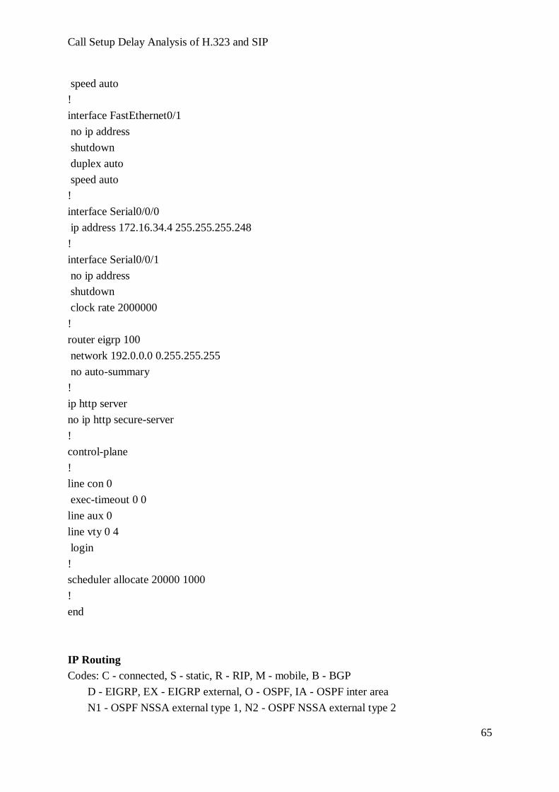
Call Setup Delay Analysis of H.323 and SIP
65
speed auto
!
interface FastEthernet0/1
no ip address
shutdown
duplex auto
speed auto
!
interface Serial0/0/0
ip address 172.16.34.4 255.255.255.248
!
interface Serial0/0/1
no ip address
shutdown
clock rate 2000000
!
router eigrp 100
network 192.0.0.0 0.255.255.255
no auto-summary
!
ip http server
no ip http secure-server
!
control-plane
!
line con 0
exec-timeout 0 0
line aux 0
line vty 0 4
login
!
scheduler allocate 20000 1000
!
end
IP Routing
Codes: C - connected, S - static, R - RIP, M - mobile, B - BGP
D - EIGRP, EX - EIGRP external, O - OSPF, IA - OSPF inter area
N1 - OSPF NSSA external type 1, N2 - OSPF NSSA external type 2

E1 - OSPF external type 1, E2 - OSPF external type 2
i - IS-IS, su - IS-IS summary, L1 - IS-IS level-1, L2 - IS-IS level-2
ia - IS-IS inter area, * - candidate default, U - per-user static route
o - ODR, P - periodic downloaded static route
Gateway of last resort is not set
D 192.168.14.0/24 [90/80005120] via 192.168.3.1, 01:52:55, FastEthernet0/0
D 192.168.4.0/24 [90/80010240] via 192.168.3.1, 01:16:11, FastEthernet0/0
10.0.0.0/24 is subnetted, 2 subnets
D 10.10.1.0 [90/80005120] via 192.168.3.1, 01:52:55, FastEthernet0/0
D 10.10.2.0 [90/80007680] via 192.168.3.1, 01:52:55, FastEthernet0/0
D 192.58.7.0/24 [90/80133120] via 192.168.3.1, 01:52:55, FastEthernet0/0
D 192.168.7.0/24 [90/80005120] via 192.168.3.1, 01:52:55, FastEthernet0/0
D 192.168.50.0/24 [90/80005120] via 192.168.3.1, 01:52:57, FastEthernet0/0
C 192.168.3.0/24 is directly connected, FastEthernet0/0
IP Interface Brief
Interface IP-Address OK? Method Status Protocol
FastEthernet0/0 192.168.3.10 YES manual up up
FastEthernet0/1 unassigned YES manual administratively down down
Serial0/0/0 172.16.34.4 YES NVRAM down down
Serial0/0/1 unassigned YES manual administratively down down
Appendix F Switch Configuration
Building configuration...
Current configuration : 1930 bytes
!
version 12.2
no service pad
service timestamps debug uptime
service timestamps log uptime
no service password-encryption
!
hostname Switch

Call Setup Delay Analysis of H.323 and SIP
67
!
no aaa new-model
system mtu routing 1500
ip subnet-zero
!
no file verify auto
spanning-tree mode pvst
spanning-tree extend system-id
!
vlan internal allocation policy ascending
!
interface FastEthernet0/1
switchport trunk encapsulation dot1q
switchport mode trunk
!
interface FastEthernet0/2
!
interface FastEthernet0/3
switchport access vlan 10
switchport mode access
!
interface FastEthernet0/4
switchport access vlan 10
switchport mode access
!
interface FastEthernet0/5
switchport access vlan 10
switchport mode access
!
interface FastEthernet0/6
switchport access vlan 10
switchport mode access
!
interface FastEthernet0/7
switchport access vlan 20
switchport mode access
!
interface FastEthernet0/8
switchport mode access
!
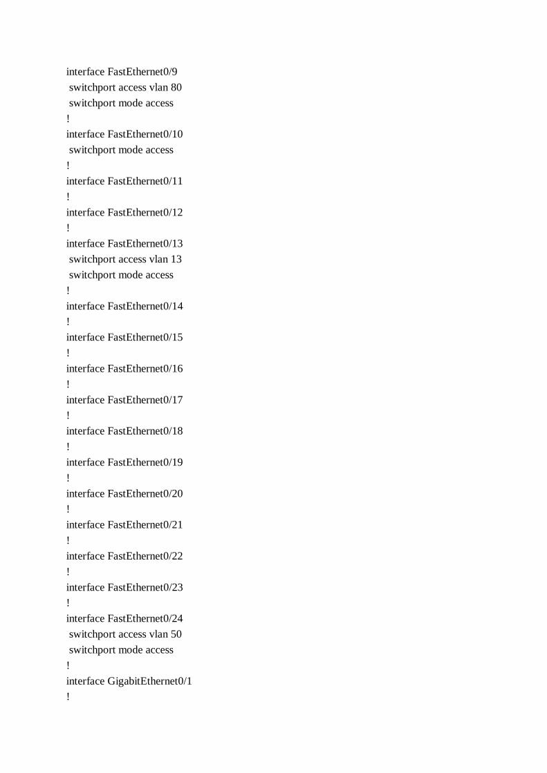
interface FastEthernet0/9
switchport access vlan 80
switchport mode access
!
interface FastEthernet0/10
switchport mode access
!
interface FastEthernet0/11
!
interface FastEthernet0/12
!
interface FastEthernet0/13
switchport access vlan 13
switchport mode access
!
interface FastEthernet0/14
!
interface FastEthernet0/15
!
interface FastEthernet0/16
!
interface FastEthernet0/17
!
interface FastEthernet0/18
!
interface FastEthernet0/19
!
interface FastEthernet0/20
!
interface FastEthernet0/21
!
interface FastEthernet0/22
!
interface FastEthernet0/23
!
interface FastEthernet0/24
switchport access vlan 50
switchport mode access
!
interface GigabitEthernet0/1
!

Call Setup Delay Analysis of H.323 and SIP
69
interface GigabitEthernet0/2
!
interface Vlan1
no ip address
shutdown
!
interface Vlan10
no ip address
!
interface Vlan13
ip address 192.168.14.2 255.255.255.0
!
ip classless
ip http server
!
control-plane
!
line con 0
line vty 0 4
login
line vty 5 15
login
!
monitor session 1 source vlan 10 - 20 rx
monitor session 1 destination interface Fa0/13
end
Vlan
VLAN Name Status Ports
---- -------------------------------- --------- -------------------------------
1 default active Fa0/2, Fa0/8, Fa0/10, Fa0/11
Fa0/12, Fa0/14, Fa0/15, Fa0/16
Fa0/17, Fa0/18, Fa0/19, Fa0/20
Fa0/21, Fa0/22, Fa0/23, Gi0/1
Gi0/2
10 data active Fa0/3, Fa0/4, Fa0/5, Fa0/6
13 VLAN0013 active Fa0/13
15 VLAN0015 active
20 voice active Fa0/7
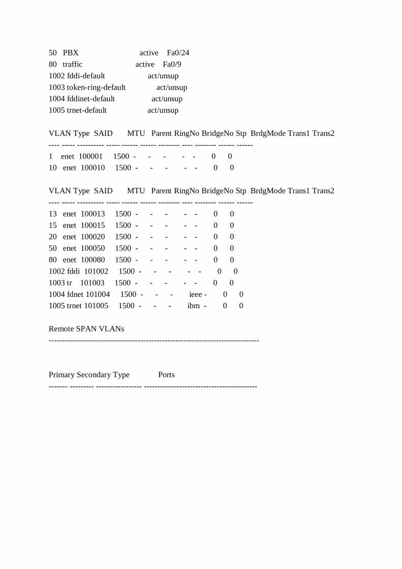
50 PBX active Fa0/24
80 traffic active Fa0/9
1002 fddi-default act/unsup
1003 token-ring-default act/unsup
1004 fddinet-default act/unsup
1005 trnet-default act/unsup
VLAN Type SAID MTU Parent RingNo BridgeNo Stp BrdgMode Trans1 Trans2
---- ----- ---------- ----- ------ ------ -------- ---- -------- ------ ------
1 enet 100001 1500 - - - - - 0 0
10 enet 100010 1500 - - - - - 0 0
VLAN Type SAID MTU Parent RingNo BridgeNo Stp BrdgMode Trans1 Trans2
---- ----- ---------- ----- ------ ------ -------- ---- -------- ------ ------
13 enet 100013 1500 - - - - - 0 0
15 enet 100015 1500 - - - - - 0 0
20 enet 100020 1500 - - - - - 0 0
50 enet 100050 1500 - - - - - 0 0
80 enet 100080 1500 - - - - - 0 0
1002 fddi 101002 1500 - - - - - 0 0
1003 tr 101003 1500 - - - - - 0 0
1004 fdnet 101004 1500 - - - ieee - 0 0
1005 trnet 101005 1500 - - - ibm - 0 0
Remote SPAN VLANs
------------------------------------------------------------------------------
Primary Secondary Type Ports
------- --------- ----------------- ------------------------------------------