calibration of diameter standards - kcdb.bipm.org key comparison calibration of diameter standards...
TRANSCRIPT

EURAMET.L-K4.2015 Key Comparison
Calibration of Diameter Standards
EURAMET project 1410
Technical protocol
(rev3.2– Jan 2017)
Istituto Nazionale di Ricerca Metrologica
Strada delle Cacce 91
10135 Torino, Italy
Gian Bartolo Picotto, January 2017
EURAMET.L‐K4.2015 Key Comparison Calibration of Diameter Standards Technical protocol
Technical‐protocol_EURAMET.L‐K4.2015_rev3.2_final.docx Pg. 1/25
Contents
1 Document control ................................................................................................................................ 2
2 Introduction ......................................................................................................................................... 2
3 Organization ......................................................................................................................................... 2
3.1 Participants .................................................................................................................................. 2
3.2 Schedule ....................................................................................................................................... 5
3.3 Reception, transportation, insurance, costs ................................................................................ 6
4 Artefacts ............................................................................................................................................... 7
4.1 Description of artefacts ................................................................................................................ 7
5 Measuring instructions ........................................................................................................................ 8
5.1 Handling the artefact ................................................................................................................... 8
5.2 Mounting the artefacts ................................................................................................................ 8
5.3 Traceability ................................................................................................................................... 9
5.4 Measurands ................................................................................................................................. 9
5.5 Measurement uncertainty ......................................................................................................... 10
6 Reporting of results ............................................................................................................................ 11
6.1 Results and standard uncertainties as reported by participants ............................................... 11
7 Analysis of results .............................................................................................................................. 11
7.1 Calculation of the diameter KCRV .............................................................................................. 11
7.2 Artefact instability ...................................................................................................................... 12
7.3 Correlation between laboratories ............................................................................................. 12
7.4 Linking of result to other comparisons ...................................................................................... 12
Appendix A – Reception of Standards ....................................................................................................... 13
Appendix B – Conditions of Measuring Surfaces ....................................................................................... 14
Appendix C1 –Description of the INTERNAL DIAMETER measurement process ....................................... 15
Appendix C2 – Description of the EXTERNAL DIAMETER measurement process ...................................... 16
Appendix C3 – Description of the SPHERE DIAMETER measurement process .......................................... 17
Appendix C4 – Description of the ROUNDNESS/STRAIGHTNESS process .................................................. 18
Appendix D1 – Results Report Form .......................................................................................................... 19
Appendix D2 – Results Report Form .......................................................................................................... 20
Appendix D3 – Results Report Form .......................................................................................................... 21
Appendix D4 – Results Report Form .......................................................................................................... 22
Appendix E1 – Uncertainty Component Reporting Form .......................................................................... 23
Appendix E2 – Functional Uncertainty Report Form ................................................................................ 24
EURAMET.L‐K4.2015 Key Comparison Calibration of Diameter Standards Technical protocol
Technical‐protocol_EURAMET.L‐K4.2015_rev3.2_final.docx Pg. 2/25
1 Document control
Version Draft A1 Issued on September 2016; Version Draft A2 Issued on October 2016; Version Draft A3 Issued on November 2016; Version rev1 Issued on November 2016; Version rev2 Issued on December 2016; Version rev3.1 Issued on January 2017; Version rev3.2_final Issued on January 2017.
2 Introduction
The metrological equivalence of national measurement standards and of calibration certificates issued by national metrology institutes is established by a set of key and supplementary comparisons chosen and organized by the Consultative Committees of the CIPM or by the regional metrology organizations in collaboration with the Consultative Committees.
At its meeting in October 2014, the EURAMET TC for Length, decided upon a key comparison on diameter gauges, named EURAMET.L‐K4.2015, with INRIM as the pilot laboratory, following the comparison CCL‐K4.2015. The EURAMET comparison will be registered by November2016, artefact circulation shall start in November 2016 and will be completed in February 2018.
The procedures outlined in this document cover the technical procedure to be followed during the measurements. A goal of the CCL key comparisons for topics in dimensional metrology is to demonstrate the equivalence of routine calibration services offered by NMIs to clients, as listed in Appendix C of the Mutual Recognition Agreement (MRA). To this end, participants in this comparison agree to use the same apparatus and methods as routinely applied to client artefacts.
By their declared intention to participate in this key comparison, laboratories accept the general instructions and to strictly follow the technical protocol of this document. Due to the large number of participants, it is very important that participating NMIs perform their measurements during assigned dates. Participants should keep in mind that the allocated time period is not only for measurements, but transportation and customs clearance as well. Once the protocol and list of participants has been agreed, no change to the protocol or list of participants may be made without prior agreement of all participants.
3 Organization
3.1 Participants
BEV, CEM, CMI, DTI, EIM, FSB, GUM, INM, INRIM, LNE, MBM, METAS, MKEH, NSAI, PTB, SASO, SP, UME, VSL, VTT/MIKES.
Table 1. List of participant laboratories and their contacts.
Laboratory Code
Contact person, Laboratory Phone, Fax, email
INRIM Gian Bartolo Picotto INRIM Strada delle Cacce 91 10135 Torino, Italy
Tel: +39 011 3919969 Fax: +39 011 3919959 [email protected]
BEV Michael Matus BEV Arltgasse 35, 1160 Wien Austria
Tel: +43 1 211106540, Fax : +43 1 211106000 [email protected]
EURAMET.L‐K4.2015 Key Comparison Calibration of Diameter Standards Technical protocol
Technical‐protocol_EURAMET.L‐K4.2015_rev3.2_final.docx Pg. 3/25
CEM Emilio PrietoRafael Muñoz Aelio A. Arce Centro Español de Metrología (CEM) C/del Alfar 2 28760 Tres Cantos (Madrid) Spain
Tel: +34 918074716 Tel: +34 918074801 Fax: +34 91 807 48 07 [email protected] [email protected] [email protected]
CMI Václav Duchoň Czech Metrology Institute Okružní 31 638 00 Brno Czech Republic
Tel: +420 545 555 207 Fax: +420 545 555 183 [email protected]
DTI Jens Bo Toftegaard Danish Technological Institute Gregersensvej 2630 Taastrup, Denmark
Tel: +45 72 20 20 00 [email protected]
EIM Christos Bandis Hellenic Institute of Metrology (EIM) Industrial Area of Thessaloniki, Block 45 57022 Sindos, Thessaloniki Greece
Tel: +30 2310 569 999 FAX: +30 2310 569 996 [email protected]
EMI – UAE* Ahmad Dahlan Emirates Metrology Institute, Centre of Excellence for Applied research and Training ‐ CERT, Sultan bin Zayed the First Street, P.O.Box 853, Abu Dhabi, United Arab Emirates
Tel: +971 (0) 2 406 6530 Fax: +971 (0) 2 406 6677 [email protected]
FSB Gorana Baršić FSB‐National Laboratory for Length Ivana Lučića 1 RH ‐ 10000 Zagreb, 1000 Zagreb Croatia
Tel: +385 1 6168 180 Fax: +385 1 6168 599 [email protected]
GUM Zbigniew Ramotowski Central Office of Measures (GUM) ul. Elektoralna 2 00‐139 Warszawa Poland
Tel.: +48 22 581 95 43 Fax: +48 22 581 93 92 [email protected]
INM Alexandru Duta BRML‐INM National Institute of Metrology Sos. Vitan‐Bârzesti 11 042122 Bucharest 4 Romania
Tel: +40 21 334 5060 Fax: +40 21 334 5345 [email protected]
INTI Bruno Gastaldi INTI –Instututo Nacional de Tecnologia Industrial Avenida Velez Sarsfield 1561 X5000JKC CORDOBA Argentina
Tel: +54 351 4604173 ext 159 Fax: +54 351 4681021 [email protected]
LNE José SalgadoLaboratoire national de métrologie et d'essais 25, avenue Albert Bartholomée F‐75015 Paris France
Tel: +33 1 40 43 39 57 Fax: +33 1 40 43 37 37 Jose‐[email protected]
EURAMET.L‐K4.2015 Key Comparison Calibration of Diameter Standards Technical protocol
Technical‐protocol_EURAMET.L‐K4.2015_rev3.2_final.docx Pg. 4/25
MBM Gordana Bajic Montenegrin Bureau of Metrology (MBM) Kralja Nikole 2 81000 Podgorica Montenegro
Tel: +382 20 601 360 Fax: +382 20 634 651 [email protected]
METAS Rudolf Thalmann Federal Institute of Metrology METAS (METAS) Lindenweg 50 CH‐3003 Bern‐Wabern Switzerland
Tel: +41 58 387 0385 Fax: +41 58 387 0210 [email protected]
MKEH Edit BánrétiMKEH Nemetvolgyi ut 37‐39 H‐1124 Budapest Hungary
Tel: +3614585997Fax: +3613550598 [email protected]
NSAI Rory Hanrahan NSAI National Metrology Laboratory Griffith Avenue Extension Glasnevin Dublin 11 D11 E527Ireland
Tel: +353 1 808 2611 Fax: +353 1 808 2603 [email protected]
PTB Otto JuskoPhysikalisch‐Technische Bundesanstalt (PTB) Bundesallee 100 38116 Braunschweig Germany
Tel: +49 531 592 5310 Fax: +49 531 592 5310 [email protected]
SASO NMCC Nasser M. Alqahtani SASO –Length Measurements Department AI Muhammadiyah ‐ in front of King Saud University P.O.Box: 3437 Riyadh 11471 Riyadh Saudi Arabia
Tel: 00966‐11‐2529733 Fax: 00966‐11 ‐2076484 [email protected] www.saso.gov.sa
SP Sten Bergstrand SP Sveriges Tekniska Forskningsinstitut Brinellgatan 4 Borås SE‐50462 Sweden
Tel: +46 10 516 57 73 Fax: +46 10 516 56 20 [email protected]
UME Okhan Ganioglu İlker Meral Murat Aksulu TÜBİTAK UME Ulusal Metroloji Enstitüsü TÜBİTAK Gebze Yerleşkesi Barış Mah. Dr.ZekiAcarCad. No:1 41470 Gebze / Kocaeli Türkiye
Tel: +90 262 679 50 00 (ext. 5303) Fax: +90 262 679 50 01 [email protected] [email protected] [email protected]
VSL Rob H. Bergmans VSL (VSL) Thijsseweg 11 2629 JA Delft Netherlands
Tel: +31 15 269 16 41 Fax: +31 15 261 29 71 [email protected]

EURAMET.L‐K4.2015 Key Comparison Calibration of Diameter Standards Technical protocol
Technical‐protocol_EURAMET.L‐K4.2015_rev3.2_final.docx Pg. 5/25
VTT MIKES Antti LassilaVTT MIKES Tekniikantie 1 FI‐02150 Espoo Finland
Tel: +358 40 767 8584 [email protected]
* Remark: At the time of finalizing this technical protocol, EMI – UAE is not a NMI or DI and thus participates in this comparison informally. A change of the status of EMI – UAE might, however, occur during the execution of this comparison.
3.2 Schedule
The participating laboratories are asked to check a schedule, as given in table 2. If not accepted they are asked to specify a preferred timetable slot for their own measurements of the diameter gauges. Final timetable will be drawn up taking as much as possible these preferences into account. Each laboratory has five weeks that include customs clearance, calibration and transportation to the following participant. The periods including the end of year and summer holidays are extended for two weeks.
With its confirmation to participate, each laboratory is obliged to perform the measurements in the allocated period and to allow enough time in advance for transportation so that the following participant receives them in time. If a laboratory hastechnical problems to perform the measurements or customs clearance takes too long, the laboratory has to contact the pilot laboratory as soon as possible and, according to whatever it decides, it might eventually be obliged to send the standards directly to the next participant before completing the measurements or even without doing any measurements.
Table 2. Draft schedule of the comparison.
Group1
RMO Laboratory Starting date of measurement /group1
EURAMET INRIM 10 October 2016
BEV 23 November 2016
CEM 09 January 2017
CMI 13 February 2017
DTI 20 March 2017
FSB 24 April 2017
GUM 29 May 2017
INM 03 July 2017
LNE 21 August 2017
METAS 02 October 2017
VSL 06 November 2017
EIM 11 December 2017
Pilot Lab INRIM 29 January 2018

EURAMET.L‐K4.2015 Key Comparison Calibration of Diameter Standards Technical protocol
Technical‐protocol_EURAMET.L‐K4.2015_rev3.2_final.docx Pg. 6/25
Group2
RMO Laboratory Starting date of measurement /group2 (with ATA carnet)
EURAMET INRIM 05 December 2016
METAS 23 January 2017
SP 27 February 2017
MKEH 03 April 2017
NSAI 08 May 2017
CEM 12 June 2017
VTT‐MIKES 31 July 2017
UME 18 September 2017
MBM 23 October 2017
PTB 27 November 2017
SASO NMCC 08 January 2018
EMI‐UAE 12 February 2018
INTI 19 March 2018
Pilot Lab INRIM 23 April 2018
3.3 Reception, transportation, insurance, costs
A plastic/metal case containing 2 rings, 2 plugs and a sphere is used for the transportation of the artefacts (Figure 1). Upon reception of the package, each laboratory has to check that the content is complete and that there is no apparent damage on the box or any of the standards. The reception has to be confirmed immediately to the pilot with a copy to the former participant (sender), preferably using the form of Appendix A.
The organization costs will be covered by the pilot laboratory, which include the standards themselves, the cases and packaging, and the shipping costs to the next laboratory. The pilot laboratory has no insurance for any loss or damage of the standards during the circulation.
Figure 1 – Transporting cases of the gauges (group1 left, group 2 right)
Once the measurements have been completed, the package shall be sent to the following participant. The steel diameter gauges need to be protected against corrosion when not being measured by means of protective oil. Please cover them with this product before packing them for transportation or when stored for more than three days.
EURAMET.L‐K4.2015 Key Comparison Calibration of Diameter Standards Technical protocol
Technical‐protocol_EURAMET.L‐K4.2015_rev3.2_final.docx Pg. 7/25
Each participating laboratory shall cover the costs of shipping and transport insurance against loss or damage. The package should be shipped with a reliable parcel service of its choice. Once the measurements have been completed, please inform the pilot laboratory and the following participant when the package leaves your installations indicating all pertinent information. If, at any point during circulation, the package is damaged, it shall be repaired by the laboratory before shipping it again.
For the group2 the package is accompanied by an ATA carnet. Outside EU the carnet shall always be shipped with the package, never inside the box, but apart. Please be certain, that when receiving the package, you also receive the carnet! For shipment inside the EU the ATA carnet may be shipped inside the box.
4 Artefacts
4.1 Description of artefacts
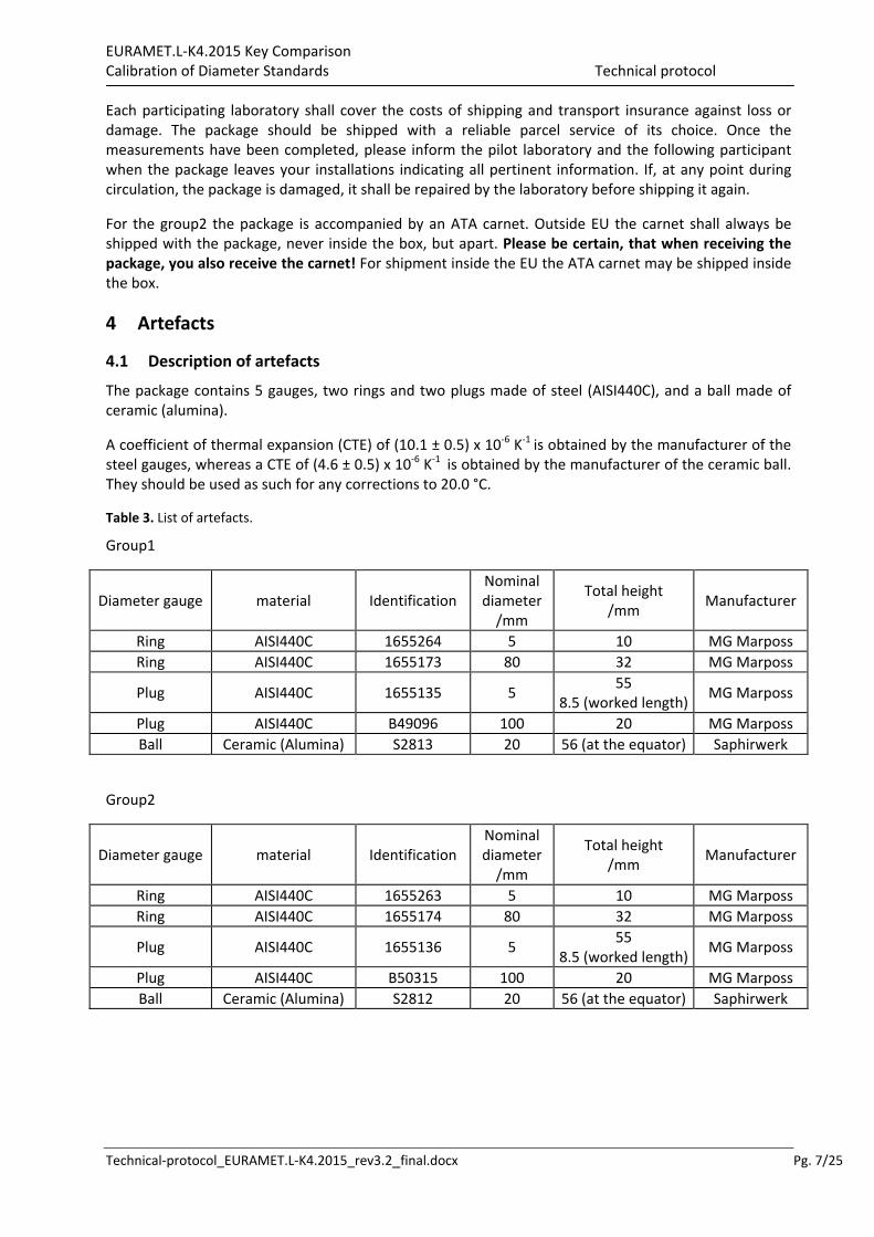
The package contains 5 gauges, two rings and two plugs made of steel (AISI440C), and a ball made of ceramic (alumina).
A coefficient of thermal expansion (CTE) of (10.1 ± 0.5) x 10‐6 K‐1 is obtained by the manufacturer of the steel gauges, whereas a CTE of (4.6 ± 0.5) x 10‐6 K‐1 is obtained by the manufacturer of the ceramic ball. They should be used as such for any corrections to 20.0 °C.
Table 3. List of artefacts.
Group1
Diameter gauge material Identification Nominal diameter/mm
Total height /mm
Manufacturer
Ring AISI440C 1655264 5 10 MG Marposs
Ring AISI440C 1655173 80 32 MG Marposs
Plug AISI440C 1655135 5 55
8.5 (worked length) MG Marposs
Plug AISI440C B49096 100 20 MG Marposs
Ball Ceramic (Alumina) S2813 20 56 (at the equator) Saphirwerk
Group2
Diameter gauge material Identification Nominal diameter/mm
Total height /mm
Manufacturer
Ring AISI440C 1655263 5 10 MG Marposs
Ring AISI440C 1655174 80 32 MG Marposs
Plug AISI440C 1655136 5 55
8.5 (worked length) MG Marposs
Plug AISI440C B50315 100 20 MG Marposs
Ball Ceramic (Alumina) S2812 20 56 (at the equator) Saphirwerk

EURAMET.L‐K4.2015 Key Comparison Calibration of Diameter Standards Technical protocol
Technical‐protocol_EURAMET.L‐K4.2015_rev3.2_final.docx Pg. 8/25
Figure 2 – Diameter gauges
5 Measuring instructions
5.1 Handling the artefact
The diameter gauges should only be handled by authorized persons and stored in such a way as to prevent damage. Before making the measurements, the gauges need to be checked to verify that their measuring surfaces are not damaged and do not present severe scratches and/or rust that may affect the measurement result. The condition of the gauges before measurement should be registered in the form provided in appendix B. Laboratories should attempt to measure all gauges unless doing so would damage their equipment.
No participant shall try to re‐finish measuring faces by burring, lapping, stoning, or whatsoever. No other measurements are to be attempted by the participants and the gauges should not be used for any purpose other than described in this document. The gauges may not be given to any party other than the participants in the comparison.
The gauges should be examined before despatch and any change in condition during the measurement at each laboratory should be communicated to the pilot laboratory. After the measurements, the gauges must be cleaned and greased. Ensure that the content of the package is complete before shipment. Always use the original packaging.
5.2 Mounting the artefacts
The ring, plug, and sphere standards shall be mounted by each laboratory’s own usual methods which are to be described on the measurement process description form in Appendix C. For the purposes of roundness and straightness, the artifacts should be mounted as necessary to achieve the measurements required.
ring Ø 80 mm
Plug Ø 100 mm
plug Ø 5 mm ring Ø 5 mm
ball Ø 20 mm
EURAMET.L‐K4.2015 Key Comparison Calibration of Diameter Standards Technical protocol
Technical‐protocol_EURAMET.L‐K4.2015_rev3.2_final.docx Pg. 9/25
5.3 Traceability
Length measurements should be traceable to the latest realisation of the metre as set out in the current “Mise en Pratique”. Temperature measurements should be made using the International Temperature Scale of 1990 (ITS‐90).
5.4 Measurands
The measurand is the diameter of each gauge at 20°C and corrected to zero force.
The diameter of the two rings and of the 100 mm plug should be measured at the marked lines at a distance from the top/upper surface equal to half the total height of the gauge. The upper side of the rings and of the plug are defined by the inscriptions. The lines defining the diameter measurement direction are marked on the upper sideof the two rings and of the 100 mm plug (SN B49096). Please note that the diameter measurement direction to be assumed with the 100 mm plug (SN B50315) is that given by the direction of the inscription “MARPOSS”.
The diameter of the 5 mm plug gauge should be measured at the marked line 4 mm below the top/upper surface. The upper side of the 5 mm plug is at the end of the 8 mm worked cylindrical surface. The lines defining the diameter measurement direction are marked on the not worked cylindrical surface of the plug.
Please note that for the cylindrical artefacts the lines defining the diameter measurement direction do not always cross precisely the centre of the cylinder/ring. The measurement direction shall therefore always be parallel to this line, but not necessarily coincident.
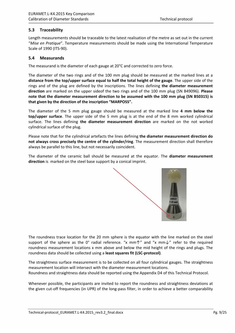
The diameter of the ceramic ball should be measured at the equator. The diameter measurement direction is marked on the steel base support by a conical imprint.
The roundness trace location for the 20 mm sphere is the equator with the line marked on the steel support of the sphere as the 0° radial reference. “x mm↑” and “x mm↓” refer to the required roundness measurement locations x mm above and below the mid height of the rings and plugs. The roundness data should be collected using a least squares fit (LSC‐protocol).
The straightness surface measurement is to be collected on all four cylindrical gauges. The straightness measurement location will intersect with the diameter measurement locations. Roundness and straightness data should be reported using the Appendix D4 of this Technical Protocol. Whenever possible, the participants are invited to report the roundness and straightness deviations at the given cut‐off frequencies (in UPR) of the long‐pass filter, in order to achieve a better comparability
EURAMET.L‐K4.2015 Key Comparison Calibration of Diameter Standards Technical protocol
Technical‐protocol_EURAMET.L‐K4.2015_rev3.2_final.docx Pg. 10/25
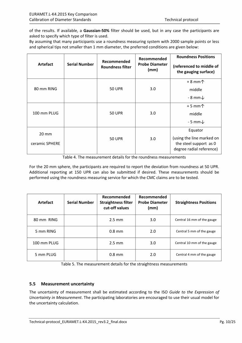
of the results. If available, a Gaussian‐50% filter should be used, but in any case the participants are asked to specify which type of filter is used. By assuming that many participants use a roundness measuring system with 2000 sample points or less and spherical tips not smaller than 1 mm diameter, the preferred conditions are given below:
Artefact Serial Number Recommended Roundness filter
Recommended Probe Diameter
(mm)
Roundness Positions
(referenced to middle of the gauging surface)
80 mm RING 50 UPR 3.0
+ 8 mm↑
middle
‐ 8 mm↓
100 mm PLUG 50 UPR 3.0
+ 5 mm↑
middle
‐ 5 mm↓
20 mm
ceramic SPHERE 50 UPR 3.0
Equator
(using the line marked on the steel support as 0 degree radial reference)
Table 4. The measurement details for the roundness measurements
For the 20 mm sphere, the participants are required to report the deviation from roundness at 50 UPR. Additional reporting at 150 UPR can also be submitted if desired. These measurements should be performed using the roundness measuring service for which the CMC claims are to be tested.
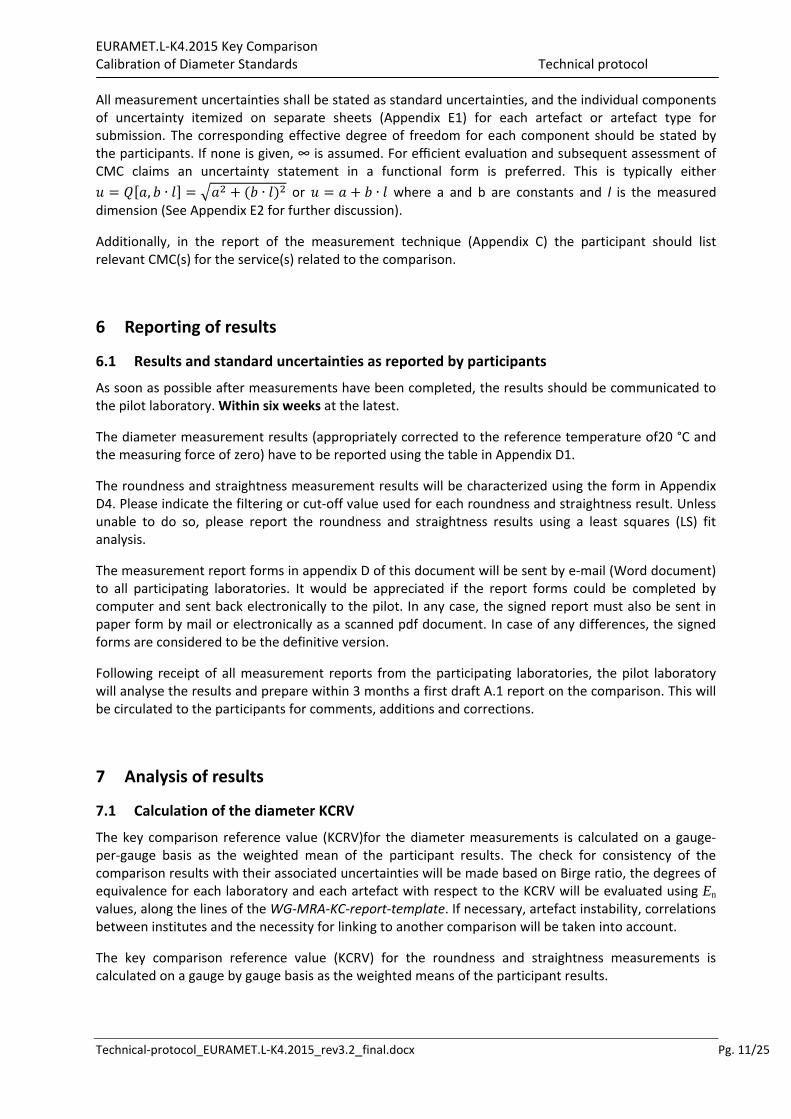
Artefact Serial Number Recommended
Straightness filter cut‐off values
Recommended Probe Diameter
(mm) Straightness Positions
80 mm RING 2.5 mm 3.0 Central 16 mm of the gauge
5 mm RING 0.8 mm 2.0 Central 5 mm of the gauge
100 mm PLUG 2.5 mm 3.0 Central 10 mm of the gauge
5 mm PLUG 0.8 mm 2.0 Central 4 mm of the gauge
Table 5. The measurement details for the straightness measurements
5.5 Measurement uncertainty
The uncertainty of measurement shall be estimated according to the ISO Guide to the Expression of Uncertainty in Measurement. The participating laboratories are encouraged to use their usual model for the uncertainty calculation.
EURAMET.L‐K4.2015 Key Comparison Calibration of Diameter Standards Technical protocol
Technical‐protocol_EURAMET.L‐K4.2015_rev3.2_final.docx Pg. 11/25
All measurement uncertainties shall be stated as standard uncertainties, and the individual components of uncertainty itemized on separate sheets (Appendix E1) for each artefact or artefact type for submission. The corresponding effective degree of freedom for each component should be stated by the participants. If none is given, ∞ is assumed. For efficient evalua on and subsequent assessment of CMC claims an uncertainty statement in a functional form is preferred. This is typically either
, ∙ ∙ or ∙ where a and b are constants and l is the measured dimension (See Appendix E2 for further discussion).
Additionally, in the report of the measurement technique (Appendix C) the participant should list relevant CMC(s) for the service(s) related to the comparison.
6 Reporting of results
6.1 Results and standard uncertainties as reported by participants
As soon as possible after measurements have been completed, the results should be communicated to the pilot laboratory. Within six weeks at the latest.
The diameter measurement results (appropriately corrected to the reference temperature of20 °C and the measuring force of zero) have to be reported using the table in Appendix D1.
The roundness and straightness measurement results will be characterized using the form in Appendix D4. Please indicate the filtering or cut‐off value used for each roundness and straightness result. Unless unable to do so, please report the roundness and straightness results using a least squares (LS) fit analysis.
The measurement report forms in appendix D of this document will be sent by e‐mail (Word document) to all participating laboratories. It would be appreciated if the report forms could be completed by computer and sent back electronically to the pilot. In any case, the signed report must also be sent in paper form by mail or electronically as a scanned pdf document. In case of any differences, the signed forms are considered to be the definitive version.
Following receipt of all measurement reports from the participating laboratories, the pilot laboratory will analyse the results and prepare within 3 months a first draft A.1 report on the comparison. This will be circulated to the participants for comments, additions and corrections.
7 Analysis of results
7.1 Calculation of the diameter KCRV
The key comparison reference value (KCRV)for the diameter measurements is calculated on a gauge‐per‐gauge basis as the weighted mean of the participant results. The check for consistency of the comparison results with their associated uncertainties will be made based on Birge ratio, the degrees of equivalence for each laboratory and each artefact with respect to the KCRV will be evaluated using En values, along the lines of the WG‐MRA‐KC‐report‐template. If necessary, artefact instability, correlations between institutes and the necessity for linking to another comparison will be taken into account.
The key comparison reference value (KCRV) for the roundness and straightness measurements is calculated on a gauge by gauge basis as the weighted means of the participant results.
EURAMET.L‐K4.2015 Key Comparison Calibration of Diameter Standards Technical protocol
Technical‐protocol_EURAMET.L‐K4.2015_rev3.2_final.docx Pg. 12/25
7.2 Artefact instability
Steel gauges occasionally show a growing or a shrinking and the rate of which is approximately linear with time. Since the artefacts used here are of unknown history, the instability of the gauges must be determined in course of the comparison. For this check the measurements of the pilot laboratory are used exclusively, not that of the other participants. Using these data a linear regression line is fitted and the slope together with its uncertainty is determined (per gauge).
Some of the gauges circulating in the two groups are twin examples from the same manufacturer and production time. Data from these twin gauges monitored by the pilot laboratory are an additional measure of material instability. These data will support conclusions determined for the circulated artefacts as necessary.
Three cases can be foreseen: a) The linear regression line is an acceptable drift model and the absolute drift is smaller than its
uncertainty. The gauge is considered stable and no modification to the standard evaluation procedure will be applied. In fact the results of the pilot’s stability measurements will not influence the numerical results in any way. The data from the supplemental twin gauges being measured in controlled conditions by the pilot laboratory support the drift decisions for the circulated artefacts.
b) The linear regression line is an acceptable drift model and the absolute drift is larger than its uncertainty, i.e. there is a significant drift for the gauge. In this case an analysis similar to [Nien F Z et al. 2004,Statistical analysis of key comparisons with linear trends, Metrologia41, 231] will be followed. The pilot influences the KCRV by the slope of the drift only, not by the measured absolute diameters. The data from the supplemental twin gauges being measured in controlled conditions by the pilot laboratory support the drift decisions for the circulated artefacts.
c) The data are not compatible at all with a linear drift, regarding the uncertainties of the pilot’s measurements. In this case the artefact is unpredictably unstable or the pilot has problems with its measurements. TC‐L has to determine the further approach.
7.3 Correlation between laboratories
Since the topic of this project is the comparison of primary measurements, correlations between the results of different NMIs are unlikely. A possible exception is the common use of the recommended thermal expansion coefficients. A correlation will become relevant only when the gauges are calibrated far away from 20 °C which should not be the case. Thus correlations are normally not considered in the analysis of this comparison. However if a significant drift exist, correlations between institutes are introduced by the analysis proposed in section 7.2.
7.4 Linking of result to other comparisons
The CCL task group on linking CCL TG‐L will set guidelines for linking this comparison to any other key comparison within CCL for the same measurement quantity.
The comparison will be linked to CCL‐K4.2015 through the linking labs INRIM, CEM and METAS. These three labs agree to participate in both groups for linking the two loops.

EURAMET.L‐K4.2015 Key Comparison Calibration of Diameter Standards Technical protocol
Technical‐protocol_EURAMET.L‐K4.2015_rev3.2_final.docx Pg. 13/25
Appendix A – Reception of Standards
To: Gian Bartolo Picotto Istituto Nazionale di Ricerca Metrologica (INRIM) Strada delle Cacce 91 10135 Torino Italy
Tel. +39 011 3919969 Fax +39 011 3919959 e‐mail: [email protected]
From: Date:
NMI:
Name:
Signature:
We confirm having received the diameter gauges for the EURAMET.L‐K4 comparison on the date given above.
After a visual inspection:
There are no apparent damages; their precise state will be reported inthe form provided in Appendix B once inspected in the laboratory along with the measurement results.
We have detected severe damages putting the measurement results at risk. Please indicate the damages, specifyingevery detail and, if possible, include photos. If it is necessary use additional sheets to report it.

EURAMET.L‐K4.2015 Key Comparison Calibration of Diameter Standards Technical protocol
Technical‐protocol_EURAMET.L‐K4.2015_rev3.2_final.docx Pg. 14/25
Appendix B – Conditions of Measuring Surfaces
To: Gian Bartolo Picotto Istituto Nazionale di Ricerca Metrologica (INRIM) Strada delle Cacce 91 10135 Torino Italy
Tel. +39 011 3919969 Fax +39 011 3919959 e‐mail: [email protected]
From: Date:
NMI:
Name:
Signature:
After detailed inspection of the measuring surfaces of the gauges, we report these findings. Please describe in words, diagrams, and photographs the nature and location of significant surface imperfections (scratches, indentations, corrosion, etc.). Please use additional sheets if necessary to describe the damages.

EURAMET.L‐K4.2015 Key Comparison Calibration of Diameter Standards Technical protocol
Technical‐protocol_EURAMET.L‐K4.2015_rev3.2_final.docx Pg. 15/25
Appendix C1 –Description of the INTERNAL DIAMETER measurement process
To: Gian Bartolo Picotto Istituto Nazionale di Ricerca Metrologica (INRIM) Strada delle Cacce 91 10135 Torino Italy
Tel. +39 011 3919969 Fax +39 011 3919959 e‐mail: [email protected]
From: Date:
NMI:
Name:
Signature:
Make and type of instrument(s) ..........................................................................................................................
.............................................................................................................................................................................
.............................................................................................................................................................................
.............................................................................................................................................................................
.............................................................................................................................................................................
Traceability path: .................................................................................................................................................
.............................................................................................................................................................................
.............................................................................................................................................................................
Description of measuring technique (including filter and cut off values, reversal, fixturing, etc.) .....................
.............................................................................................................................................................................
.............................................................................................................................................................................
.............................................................................................................................................................................
.............................................................................................................................................................................
.............................................................................................................................................................................
.............................................................................................................................................................................
.............................................................................................................................................................................
Range of gauge temperature during measurements & description of temperature measurement method: ................................................................................................................................................................
.............................................................................................................................................................................
.............................................................................................................................................................................
CMC uncertainty for the service(s) related to this comparison topic (if existing in the KCDB) ...........................
.............................................................................................................................................................................
.............................................................................................................................................................................
(use additional pages as needed)

EURAMET.L‐K4.2015 Key Comparison Calibration of Diameter Standards Technical protocol
Technical‐protocol_EURAMET.L‐K4.2015_rev3.2_final.docx Pg. 16/25
Appendix C2 – Description of the EXTERNAL DIAMETER measurement process
To: Gian Bartolo Picotto Istituto Nazionale di Ricerca Metrologica (INRIM) Strada delle Cacce 91 10135 Torino Italy
Tel. +39 011 3919969 Fax +39 011 3919959 e‐mail: [email protected]
From: Date:
NMI:
Name:
Signature:
Make and type of instrument(s) ..........................................................................................................................
.............................................................................................................................................................................
.............................................................................................................................................................................
.............................................................................................................................................................................
.............................................................................................................................................................................
Traceability path: .................................................................................................................................................
.............................................................................................................................................................................
.............................................................................................................................................................................
Description of measuring technique (including filter and cut off values, reversal, fixturing, etc.) .....................
.............................................................................................................................................................................
.............................................................................................................................................................................
.............................................................................................................................................................................
.............................................................................................................................................................................
.............................................................................................................................................................................
.............................................................................................................................................................................
.............................................................................................................................................................................
Range of gauge temperature during measurements & description of temperature measurement method: ................................................................................................................................................................
.............................................................................................................................................................................
.............................................................................................................................................................................
CMC uncertainty for the service(s) related to this comparison topic (if existing in the KCDB) ...........................
.............................................................................................................................................................................
.............................................................................................................................................................................
(use additional pages as needed)
EURAMET.L‐K4.2015 Key Comparison Calibration of Diameter Standards Technical protocol
Technical‐protocol_EURAMET.L‐K4.2015_rev3.2_final.docx Pg. 17/25
Appendix C3 – Description of the SPHERE DIAMETER measurement process
To: Gian Bartolo Picotto Istituto Nazionale di Ricerca Metrologica (INRIM) Strada delle Cacce 91 10135 Torino Italy
Tel. +39 011 3919969 Fax +39 011 3919959 e‐mail: [email protected]
From: Date:
NMI:
Name:
Signature:
Make and type of instrument(s) ..........................................................................................................................
.............................................................................................................................................................................
.............................................................................................................................................................................
.............................................................................................................................................................................
.............................................................................................................................................................................
Traceability path: .................................................................................................................................................
.............................................................................................................................................................................
.............................................................................................................................................................................
Description of measuring technique (including filter and cut off values, reversal, fixturing, etc.) .....................
.............................................................................................................................................................................
.............................................................................................................................................................................
.............................................................................................................................................................................
.............................................................................................................................................................................
.............................................................................................................................................................................
.............................................................................................................................................................................
.............................................................................................................................................................................
Range of gauge temperature during measurements & description of temperature measurement method: ................................................................................................................................................................
.............................................................................................................................................................................
.............................................................................................................................................................................
CMC uncertainty for the service(s) related to this comparison topic (if existing in the KCDB) ...........................
.............................................................................................................................................................................
.............................................................................................................................................................................
(use additional pages as needed)

EURAMET.L‐K4.2015 Key Comparison Calibration of Diameter Standards Technical protocol
Technical‐protocol_EURAMET.L‐K4.2015_rev3.2_final.docx Pg. 18/25
Appendix C4 – Description of the ROUNDNESS/STRAIGHTNESS process
To: Gian Bartolo Picotto Istituto Nazionale di Ricerca Metrologica (INRIM) Strada delle Cacce 91 10135 Torino Italy
Tel. +39 011 3919969 Fax +39 011 3919959 e‐mail: [email protected]
From: Date:
NMI:
Name:
Signature:
Make and type of instrument(s) ..........................................................................................................................
.............................................................................................................................................................................
.............................................................................................................................................................................
.............................................................................................................................................................................
.............................................................................................................................................................................
Traceability path: .................................................................................................................................................
.............................................................................................................................................................................
.............................................................................................................................................................................
Description of measuring technique (including filter and cut off values, reversal, fixturing, etc.) .....................
.............................................................................................................................................................................
.............................................................................................................................................................................
.............................................................................................................................................................................
.............................................................................................................................................................................
.............................................................................................................................................................................
.............................................................................................................................................................................
.............................................................................................................................................................................
Range of gauge temperature during measurements & description of temperature measurement method: ................................................................................................................................................................
.............................................................................................................................................................................
.............................................................................................................................................................................
CMC uncertainty for the service(s) related to this comparison topic (if existing in the KCDB) ...........................
.............................................................................................................................................................................
.............................................................................................................................................................................
(use additional pages as needed)

EURAMET.L‐K4.2015 Key Comparison Calibration of Diameter Standards Technical protocol
Technical‐protocol_EURAMET.L‐K4.2015_rev3.2_final.docx Pg. 19/25
Appendix D1 – Results Report Form
To: Gian Bartolo Picotto Istituto Nazionale di Ricerca Metrologica (INRIM) Strada delle Cacce 91 10135 Torino Italy
Tel. +39 011 3919969 Fax +39 011 3919959 e‐mail: [email protected]
From: Date:
NMI:
Name:
Signature:
Internal Diameter Ring Measurements
5 mm ring gauge, AISI440C, identification number: ……
Location Meas. diameter (mm)
std. uncert. k=1(µm)
mat. temp. (°C)
Probeconfig.& size (mm) Meas. force used (mN)
Midway (*)
0 deg.
80 mm ring gauge, AISI440C, identification number: ……
Location Meas. diameter (mm)
std. uncert. k=1(µm)
mat. temp. (°C)
Probeconfig.& size (mm) Meas. force used (mN)
Midway (*)
0 deg.
(*) Midway stands for a distance from the top/upper surface equal to half the total height of the gauge (see paragraph 5.4 Measurands)
EURAMET.L‐K4.2015 Key Comparison Calibration of Diameter Standards Technical protocol
Technical‐protocol_EURAMET.L‐K4.2015_rev3.2_final.docx Pg. 20/25
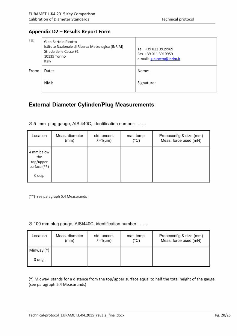
Appendix D2 – Results Report Form
To: Gian Bartolo Picotto Istituto Nazionale di Ricerca Metrologica (INRIM) Strada delle Cacce 91 10135 Torino Italy
Tel. +39 011 3919969 Fax +39 011 3919959 e‐mail: [email protected]
From: Date:
NMI:
Name:
Signature:
External Diameter Cylinder/Plug Measurements
5 mm plug gauge, AISI440C, identification number: ……
Location Meas. diameter (mm)
std. uncert. k=1(µm)
mat. temp. (°C)
Probeconfig.& size (mm) Meas. force used (mN)
4 mm below the
top/upper surface (**)
0 deg.
(**) see paragraph 5.4 Measurands
100 mm plug gauge, AISI440C, identification number: ……
Location Meas. diameter (mm)
std. uncert. k=1(µm)
mat. temp. (°C)
Probeconfig.& size (mm) Meas. force used (mN)
Midway (*)
0 deg.
(*) Midway stands for a distance from the top/upper surface equal to half the total height of the gauge (see paragraph 5.4 Measurands)
EURAMET.L‐K4.2015 Key Comparison Calibration of Diameter Standards Technical protocol
Technical‐protocol_EURAMET.L‐K4.2015_rev3.2_final.docx Pg. 21/25
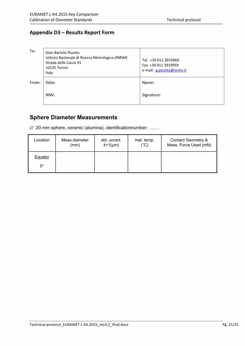
Appendix D3 – Results Report Form
To: Gian Bartolo Picotto Istituto Nazionale di Ricerca Metrologica (INRIM) Strada delle Cacce 91 10135 Torino Italy
Tel. +39 011 3919969 Fax +39 011 3919959 e‐mail: [email protected]
From: Date:
NMI:
Name:
Signature:
Sphere Diameter Measurements
20 mm sphere, ceramic (alumina), identificationnumber: ……
Location Meas.diameter (mm)
std. uncert. k=1(µm)
mat. temp. (°C)
Contact Geometry & Meas. Force Used (mN)
Equator
0°
EURAMET.L‐K4.2015 Key Comparison Calibration of Diameter Standards Technical protocol
Technical‐protocol_EURAMET.L‐K4.2015_rev3.2_final.docx Pg. 22/25
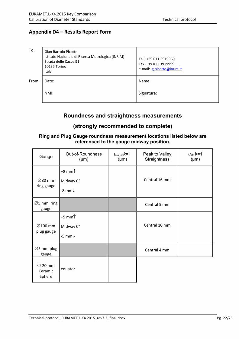
Appendix D4 – Results Report Form
To: Gian Bartolo Picotto Istituto Nazionale di Ricerca Metrologica (INRIM) Strada delle Cacce 91 10135 Torino Italy
Tel. +39 011 3919969 Fax +39 011 3919959 e‐mail: [email protected]
From: Date:
NMI:
Name:
Signature:
Roundness and straightness measurements
(strongly recommended to complete)
Ring and Plug Gauge roundness measurement locations listed below are referenced to the gauge midway position.
Gauge Out-of-Roundness
(µm) uroundk=1
(µm) Peak to Valley Straightness
ustr k=1 (µm)
80 mm ring gauge
+8 mm
Midway 0°
‐8 mm
Central 16 mm
5 mm ring gauge
Central 5 mm
100 mm plug gauge
+5 mm
Midway 0°
‐5 mm
Central 10 mm
5 mm plug gauge
Central 4 mm
20 mm Ceramic Sphere
equator
EURAMET.L‐K4.2015 Key Comparison Calibration of Diameter Standards Technical protocol
Technical‐protocol_EURAMET.L‐K4.2015_rev3.2_final.docx Pg. 23/25
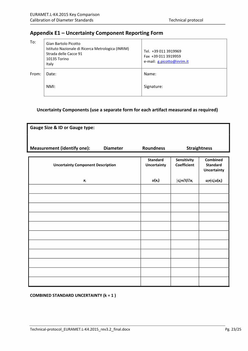
Appendix E1 – Uncertainty Component Reporting Form
To: Gian Bartolo Picotto Istituto Nazionale di Ricerca Metrologica (INRIM) Strada delle Cacce 91 10135 Torino Italy
Tel. +39 011 3919969 Fax +39 011 3919959 e‐mail: [email protected]
From: Date:
NMI:
Name:
Signature:
Uncertainty Components (use a separate form for each artifact measurand as required)
Gauge Size & ID or Gauge type:
Measurement (identify one): Diameter Roundness Straightness
Uncertainty Component Description
xi
Standard Uncertainty
u(xi)
Sensitivity Coefficient
cil/xi
Combined Standard
Uncertainty
uiciu(xi)
COMBINED STANDARD UNCERTAINTY (k = 1 )
EURAMET.L‐K4.2015 Key Comparison Calibration of Diameter Standards Technical protocol
Technical‐protocol_EURAMET.L‐K4.2015_rev3.2_final.docx Pg. 24/25
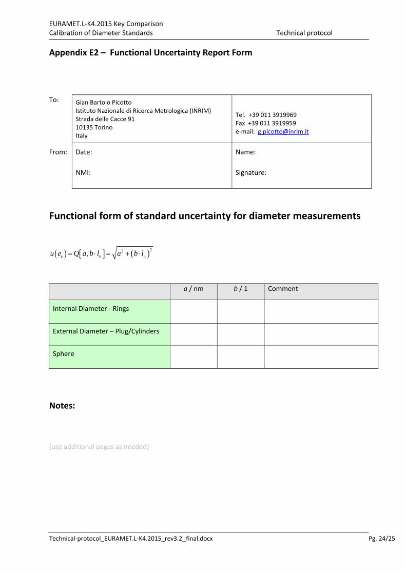
Appendix E2 – Functional Uncertainty Report Form
To: Gian Bartolo Picotto Istituto Nazionale di Ricerca Metrologica (INRIM) Strada delle Cacce 91 10135 Torino Italy
Tel. +39 011 3919969 Fax +39 011 3919959 e‐mail: [email protected]
From: Date:
NMI:
Name:
Signature:
Functional form of standard uncertainty for diameter measurements
22c n n,u e Q a b l a b l
a / nm b / 1 Comment
Internal Diameter ‐ Rings
External Diameter – Plug/Cylinders
Sphere
Notes:
(use additional pages as needed)