calculation of naca 0012 airfoil through roe’s scheme...
TRANSCRIPT

Abstract— The present work performs the Roe’s scheme in
solving Euler equation, applied to the solution of flow over 2D airfoil
NACA 0012 and compares to experimental data and XFOIL
software. As one of the approximation solvers for Riemann scheme,
Roe’s scheme is extended to second order through MUSCL scheme.
MUSCL scheme has been applied in order to eliminate the spurious
oscillation due to shock wave presence. In this work, flow is treated
as compressible with Mach number around 0.3 to 0.8 and Reynolds
number is set at 3 million. Results show a good potential have been
made by present method especially at low angle of attack and low
Mach number. To improve the accuracy of solution, present study
proposed viscous effect should be included where viscosity plays a
major role in determination of aerodynamic characteristics
particularly for high speed aerodynamic.
Keywords— Inviscid flow, Euler solver, Roe’s scheme, and
MUSCL scheme.
I. INTRODUCTION
INCE early 20th
century, aerodynamics progressively
evolved in a wide range and become very interesting
subject in engineering and mathematic. Study on flow
behavior for single airfoil is neither new nor primitive subject
in aerodynamics. Since Eastman and Abbott [1], investigation
has been made on various types of NACA airfoil through
experiment within variable-density wind tunnel.
Consequently, Eastman made another attempt which more
systematic experimentation with relating a number of
N.A.C.A airfoil in a wide range of Reynolds number [2]. In
other occasions, experimental data on single airfoil also been
carried out by Wenzinger [3], Eastman and William [4],
Abbott, Von Doenhoeff, and Stivers [5], Moyers [6], Ferri [7],
and many others.
Numerical solution on Navier Stokes equation gave major
influence in aerodynamics analysis. As example, an
investigation was made by Korn on shock-free transonic
around airfoil by applying numerical method in solving linear
partial differential equations [8]. Subsequently, many works
was made by researchers to examine the capability of solution
methods. Lax, Roe, McCormack, Godunov, Ritchmeyer and
Mohd Faizal bin Che Mohd Husin, is a PHD student of University Tun
Hussein Onn Malaysia, 86400 Johor, Malaysia (corresponding author’s phone: +6019-9789769; e-mail: [email protected]).
Dr. Ir. Bambang Basuno, is a Senior Lecturer at Department of Aeronautic,
University Tun Hussein Onn Malaysia, 86400 Johor, Malaysia (e-mail: [email protected]).
Dr. Zamri bin Omar, is a Senior Lecturer at Department of Aeronautic,
University Tun Hussein Onn Malaysia, 86400 Johor, Malaysia (e-mail: [email protected]).
Rusanov who invented applicable schemes frequently gained
attention by succeeding researchers. Taylor explained some of
favorite schemes thoroughly in dealing with such serious
difficulties of aerodynamic problem [9]. This work engaged
with a wide scope of aerodynamics properties such as
subsonic, transonic and supersonic speed, viscous and
inviscid, compressibility effect, high Reynolds numbers and
various approach of solution namely potential flow, Euler
solver and Navier stokes solution.
Behind these advances, experimental approach exhibited
similar improvement as computational one since the
technology of wind tunnel experienced successive
modification. Gregory and Wilby [10] on their study
aerodynamics characteristics of airfoil NPL9615 and NACA
0012 provided a complete data set for these airfoils at various
Mach number of subsonic flow. Consequently, Gregory made
another effort with O’Riley on NACA 0012 which including
effect of upper surface roughness [11]. Another excellent
accomplishment has been done by Harris [12] via experiment
on two-dimensional NACA 0012 within Langley 8-foot wind
tunnel where measurement is conducted at subsonic speed and
relatively high Reynolds number. Experiments on NACA
0012 were also made by Langley [13], Nash, Quincey,
Callinan [14]and Murdin[15]. All those experimental results
show uncertainty difference of each other and it caused
difficulty to validate CFD results.
Jameson carried on aerodynamics discovery with his work
on airfoils through numerical potential flow solution [16]. This
work offers the solution of flow at sonic Mach number and
also implements artificial viscosity as a shockwave treatment.
The great work by Jameson on Euler methods can be found in
[17] by solving Euler equation with finite volume methods.
Those methods were solved by Runge-Kutta time stepping
schemes. Engaged with time stepping schemes, accuracy of
solution was improved and the stability region can be
extended. The latest work, which dealing with Euler equation
is by Arias et. al[18]. In this research finite volume has been
simulated for a flow over airfoil NACA 0012 by using
Jameson, MacCormack, Shue, and TVD schemes. This work
presented two computer codes where both approach
implement finite volume methods to solve Euler equations.
First code namely ITA works on two-dimensional structured
grid and it possess the capacity to work with three different
schemes: (i) the Jameson scheme using a five stage Runge-
Kutta time integration; (ii) the MacCormack scheme, based
upon the predictor and corrector strategy to advance in time;
Calculation of NACA 0012 Airfoil through
Roe’s Scheme Method
Mohd Faizal bin Che Mohd Husin, Dr. Ir. Bambang Basuno, and Dr. Zamri bin Omar
S
International Conference Recent treads in Engineering & Technology (ICRET’2014) Feb 13-14, 2014 Batam (Indonesia)
http://dx.doi.org/10.15242/IIE.E0214521 51

(iii) and finally the Shu scheme, which uses a variation of the
Jameson time integration, in order to better capture of shock
waves.
Another effort that related to present work is explained by
Maciel [19] which demonstrated several high resolution of
TVD’s scheme to be dealt with two-dimension aerodynamic
problem. There are six schemes employed here namely Roe’s,
Van Leer vector splitting, Harten-Yee, Yee-Kutler and,
Hugson-Beran. In order to reach accuracy of second order,
Roe and Van Leer scheme apply MUSCL approach and other
schemes used Harten’s ideas of the construction of a modified
flux function to obtain second order accuracy and TVD
characteristics. This paper also offered solution in both of
formulation: implicit and explicit. Implicit solved through
ADI (“Alternating Direction Implicit”) approximate
factorization while the explicit one’s used a time splitting
method. Lastly, study concluded that Roe’s scheme exhibit the
best agreement to the experimental results both in the implicit
and explicit formulation due to the best estimative of the
shock angle.
II. PROCEDURE FOR COMPUTATION
Present airfoil analysis is employing with Euler equation to
deal with two-dimension inviscid flow over airfoil NACA
0012. Euler equation will be treated in explicit formulation.
Roe’s TVD scheme is utilized to resolve this explicit Euler
equation with MUSCL’s scheme is exploited to increase
accuracy of second order formulation. In order to apply these
methods to complex geometric configurations, the finite
volume formulation has been used to develop the space
discretization, and allows the implementation of an arbitrary
grid. Structured numerical grid generation is used since the
problem of single airfoil NACA 0012 is considered as
relatively straightforward configuration. To accomplish the
goal above computer codes for TVD scheme and grid
generation were utilized, which had taken from Blazek [20].
The criterion must be satisfied by grid generation process were
1) they domain is completely covered by the grid, 2) there is
no free space left between the grid cells, and 3) the grid cells
do not overlap each other. The detail about its governing
equation would be described in the next section. The results of
the study are mainly focused on pressure distribution, lift
coefficient and moment coefficient. Due to Euler solution for
inviscid flow domain, aerodynamics characteristics mentioned
is sufficient enough without taking account of drag coefficient
since the viscosity effect that affected the airfoil surface
characteristics are neglected. Computer code that introduced
in [20] is utilized namely AIRFOIL_ROE_SCHEME in
solving the objective of study.
There are plenty of experimental data can be used as a
weighing scale for analysis, however it must be chosen
depends on fundamental of experiment. The work of Gregory
and Wilby [10] and, Gregory and O’Riley [11] were reliable
and matched to be an assessment data set since experiment
was conducted at subsonic flow and Reynolds number about
2.88 X 10⁶. Moreover, it will facilitate comparison process
where the results of experiment represent pressure coefficient
distribution CP [11], lift coefficient CL, and moment
coefficient CM [10]. For the high Mach number, experimental
data have been taken from Harris in [21] as suggested in [22].
Another comparison has been made with aerodynamics
software namely XFOIL by Drela where represents a
combination of panel method and global Newton method.
Resolution that offered by XFOIL mainly applicable for low
Reynolds number case, while at high Reynolds number case,
software exhibit inconsistence results. A brief description of
Euler solution and computer code is shown in the next section.
III. THE GOVERNING EQUATION
A. Description of Euler Solution
The governing equation of inviscid flow domain for the
case of compressible, non-viscous and two dimensional
unsteady flows in conservative form is [23]:
Where:
[
] [
], [
] }
With:
(
)
}
Above equation is known as Compressible Euler Equation
and represents a highly nonlinear partial differential equation
and there is no analytical solution. denotes as the ratio of
specific heat capacities of the gas. In a two dimensional, Euler
equation is wrote in hyperbolic equation form.
Where A and B is Jacobian matrix system
[
]
}
For more convenience, it is wise if Euler equation is derived
in one dimensional then for future use, one can simply extend
to multi-dimensional. One dimensional explicit time stepping
formulation read as:
(
) [
]
Following the step of Roe’s scheme, each term in (6) are
derived as follow [24]:
International Conference Recent treads in Engineering & Technology (ICRET’2014) Feb 13-14, 2014 Batam (Indonesia)
http://dx.doi.org/10.15242/IIE.E0214521 52

(
)
(∑|
|
)
First terms of right hand side equation represents convective
flux while the second terms are dissipative flux. Convective
flux is treated by upwind scheme, and dissipative flux will
follow Roe high resolution scheme. is eigenvector matrix
correspondents to matrix eigenvalues respects to similarity
such that [25]:
[
] [
]
D and X-1
are matrix diagonal and inverse eigenvector
matrix respectively and speed of sound, √ . All quantities with the hat that appears in (9) are evaluated by
Roe average:
√ √
√ √ √
√ √
√ √ √ ( )
√ √
√ √
√ √
√ √
As an Riemann approximation solver, Roe’s scheme reads
[26].
(
)
(∑| |
)
(
)
(∑| |
)
According to [24] and [27] Roe’s vector terms in (10-11) is
formulated as:
∑| |
Hence, (10-11) turns to the following forms.
( (
) (
))
( (
) (
))
With MUSCL’s interpolation, velocity terms in (13-14) are
formulated as follow [28].
Where:
[( )
( )
]
[( )
( )
]
is a free parameter lies in interval [-1,1], where for
, is a central difference approximation, multiplied by
, to the first spatial derivative of the numerical of the
numerical solution at the time level n. MUSCL’s interpolation
can be more accurate with quadratic reconstruction, that are
[20]:
}
With
and
, and following definition:
}
Thus:
[( ) (
) ( ) ]
[( ) (
) ( ) ]
It can be written as:
With:
[( ) (
) ( ) ]
International Conference Recent treads in Engineering & Technology (ICRET’2014) Feb 13-14, 2014 Batam (Indonesia)
http://dx.doi.org/10.15242/IIE.E0214521 53

[( ) (
) ( ) ]
The (15) can be simplified if we consider slope limiters
with the symmetry property as:
(
)
Thus, (15) becomes:
[ ]
[ ] }
With limiter function is defined as:
[( ) ( )]
MUSCL scheme is divided into two category where it is
determined by value of . MUSCL0 represents and
MUSCL3 for
For the MUSCL3 for
, Van Albada
flux limiter, and limiter function, followed below
expression.
}
For simplification purpose, Eq (26) is written in this form:
Where:
The additional parameter in (29) prevents the activation
of the limiter in smooth flow regions due to small-scale
oscillations [20]. This is sometimes necessary in order to
achieve a fully converged steady-state solution. For this
purpose, is set at 0.00001 while other alphabets are defined
as follow.
}
In order to increase the accuracy and to extend the stability
region [17], solution is enhanced by Runge-Kutta multistep
method. It first has been developed by Jameson [18] with
applying a five-stage Runge-Kutta to advance the solution in
time. Updating solution due to Runge-Kutta methods, it
follows steps below.
Generating grid for computational space can be undergone
in various techniques. Present study uses structured grid C-
type as obtained by Blazek [20] namely
C_GRID_GENERATOR. This method is dealt with elliptic
partial differential equation or specifically Poisson equation. C
type is one of the grid topology which is enclosed by one
family of grid lines and also forms the wake region. The
situation is shown is Fig 3.1 where lines start at
the farfield ( , follow the wake, pass the trailing edge
(node b), surround the body in clockwise, then reach farfield
again at ( . For the other grid lines exudes
in normal direction from the body and wake. The coordinate
cut that is represented by segment of a-b of grid lines at
physically map onto two segments in the
computational space namely and for
lower space and upper space respectively.
Fig. 3.1: C-grid topology in two-dimension
Elliptic equations for the two-dimension grid generation are:
(
)
(
)
(
)
(
)
Where metrics coefficient in equation are:
International Conference Recent treads in Engineering & Technology (ICRET’2014) Feb 13-14, 2014 Batam (Indonesia)
http://dx.doi.org/10.15242/IIE.E0214521 54

(
)
(
)
(
)
(
)
IV. RESULT AND ANALYSIS
Numerical high resolution of Euler’s solver scheme namely
Roe’s scheme is represented in this section. An illustration
about computational space is portrayed in Fig 4.1, where it is a
result from C_GRID_GENERATOR code. Pressure
coefficient of airfoil NACA 0012 is observed as shown in Fig
4.2, an agreement between experiment and computation is
achieved in excellent manner for low angle of attack and low
Mach number (M = 0.3) cases. At high angle of attack within
low Mach number, Roe’s solver still provides fairly prediction
as XFOIL did. At Mach number 0.8, a wide deviation is
occurred due to shock wave presence. As shown in Fig 4.2 a
good agreement is achieved ahead shock wave come off, and
Roe’s scheme exposes poor capability to capture such
phenomenon. Nonetheless, compare to software XFOIL,
Roe’s scheme remains exceptional since XFOIL software was
limited to flow at considerably low speed.
From Figs 4.2-4.5 it can be observed that two parameters
impede computational are high angle of attack and large Mach
number. Higher angle of attack affected calculation with over-
prediction occurred in tracking maximum pressure coefficient,
CP. In similar manner as present method, software XFOIL
also poses alike fashion even in determining the point of
maximum CP, XFOIL remains greater than prediction of
present method. From point of view, it simply can be realized
that the present method with no viscosity effect exhibit a good
quality in emulating experimental data. Another parameter
mentioned is Mach number. As depicted in Fig 4.4 and 4.5 for
Mach number 0.7 and 0.799 respectively, error deviates
proportionally to Mach number, where at Mach number 0.799,
with existence of shock wave, error radically exceeded 20%
chord. It implies for relatively larger Mach number as
transonic, present method remains unrealistic to be applied.
On the other hand, an excellent work done can be seen in the
Fig 4.5 where assessment of MUSCL’s interpolation scheme
plays role in diminishing spurious oscillation of shock wave.
Fig 4.1: View of structured grid about NACA 0012.
Fig. 4.2: Pressure coefficient distribution along NACA 0012
surface at angle of attack 6 and Mach number 0.3.
Fig 4.3: Pressure coefficient distribution along NACA 0012
airfoil surface at angle of attack 16.5 and Mach number 0.3.
Fig 4.4: Pressure coefficient distribution along NACA 0012
airfoil surface at angle of attack 1.49 and Mach number 0.7.
International Conference Recent treads in Engineering & Technology (ICRET’2014) Feb 13-14, 2014 Batam (Indonesia)
http://dx.doi.org/10.15242/IIE.E0214521 55
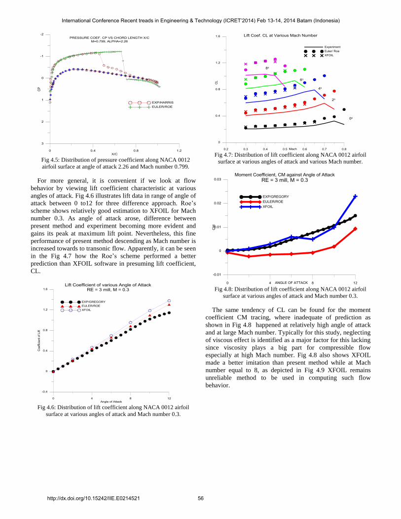
Fig 4.5: Distribution of pressure coefficient along NACA 0012
airfoil surface at angle of attack 2.26 and Mach number 0.799.
For more general, it is convenient if we look at flow
behavior by viewing lift coefficient characteristic at various
angles of attack. Fig 4.6 illustrates lift data in range of angle of
attack between 0 to12 for three difference approach. Roe’s
scheme shows relatively good estimation to XFOIL for Mach
number 0.3. As angle of attack arose, difference between
present method and experiment becoming more evident and
gains its peak at maximum lift point. Nevertheless, this fine
performance of present method descending as Mach number is
increased towards to transonic flow. Apparently, it can be seen
in the Fig 4.7 how the Roe’s scheme performed a better
prediction than XFOIL software in presuming lift coefficient,
CL.
Fig 4.6: Distribution of lift coefficient along NACA 0012 airfoil
surface at various angles of attack and Mach number 0.3.
Fig 4.7: Distribution of lift coefficient along NACA 0012 airfoil
surface at various angles of attack and various Mach number.
Fig 4.8: Distribution of lift coefficient along NACA 0012 airfoil
surface at various angles of attack and Mach number 0.3.
The same tendency of CL can be found for the moment
coefficient CM tracing, where inadequate of prediction as
shown in Fig 4.8 happened at relatively high angle of attack
and at large Mach number. Typically for this study, neglecting
of viscous effect is identified as a major factor for this lacking
since viscosity plays a big part for compressible flow
especially at high Mach number. Fig 4.8 also shows XFOIL
made a better imitation than present method while at Mach
number equal to 8, as depicted in Fig 4.9 XFOIL remains
unreliable method to be used in computing such flow
behavior.
International Conference Recent treads in Engineering & Technology (ICRET’2014) Feb 13-14, 2014 Batam (Indonesia)
http://dx.doi.org/10.15242/IIE.E0214521 56
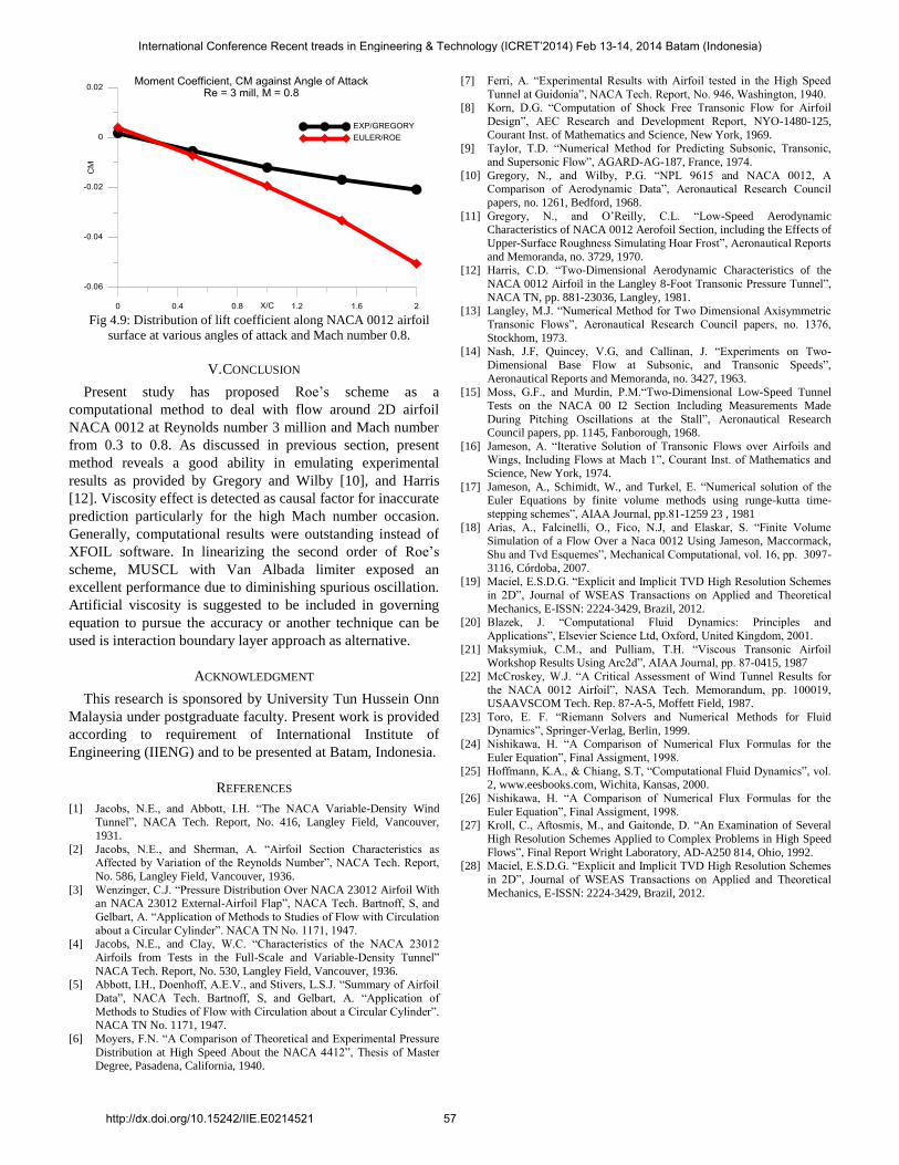
Fig 4.9: Distribution of lift coefficient along NACA 0012 airfoil
surface at various angles of attack and Mach number 0.8.
V. CONCLUSION
Present study has proposed Roe’s scheme as a
computational method to deal with flow around 2D airfoil
NACA 0012 at Reynolds number 3 million and Mach number
from 0.3 to 0.8. As discussed in previous section, present
method reveals a good ability in emulating experimental
results as provided by Gregory and Wilby [10], and Harris
[12]. Viscosity effect is detected as causal factor for inaccurate
prediction particularly for the high Mach number occasion.
Generally, computational results were outstanding instead of
XFOIL software. In linearizing the second order of Roe’s
scheme, MUSCL with Van Albada limiter exposed an
excellent performance due to diminishing spurious oscillation.
Artificial viscosity is suggested to be included in governing
equation to pursue the accuracy or another technique can be
used is interaction boundary layer approach as alternative.
ACKNOWLEDGMENT
This research is sponsored by University Tun Hussein Onn
Malaysia under postgraduate faculty. Present work is provided
according to requirement of International Institute of
Engineering (IIENG) and to be presented at Batam, Indonesia.
REFERENCES
[1] Jacobs, N.E., and Abbott, I.H. “The NACA Variable-Density Wind Tunnel”, NACA Tech. Report, No. 416, Langley Field, Vancouver,
1931.
[2] Jacobs, N.E., and Sherman, A. “Airfoil Section Characteristics as
Affected by Variation of the Reynolds Number”, NACA Tech. Report,
No. 586, Langley Field, Vancouver, 1936.
[3] Wenzinger, C.J. “Pressure Distribution Over NACA 23012 Airfoil With an NACA 23012 External-Airfoil Flap”, NACA Tech. Bartnoff, S, and
Gelbart, A. “Application of Methods to Studies of Flow with Circulation
about a Circular Cylinder”. NACA TN No. 1171, 1947. [4] Jacobs, N.E., and Clay, W.C. “Characteristics of the NACA 23012
Airfoils from Tests in the Full-Scale and Variable-Density Tunnel”
NACA Tech. Report, No. 530, Langley Field, Vancouver, 1936. [5] Abbott, I.H., Doenhoff, A.E.V., and Stivers, L.S.J. “Summary of Airfoil
Data”, NACA Tech. Bartnoff, S, and Gelbart, A. “Application of
Methods to Studies of Flow with Circulation about a Circular Cylinder”. NACA TN No. 1171, 1947.
[6] Moyers, F.N. “A Comparison of Theoretical and Experimental Pressure
Distribution at High Speed About the NACA 4412”, Thesis of Master Degree, Pasadena, California, 1940.
[7] Ferri, A. “Experimental Results with Airfoil tested in the High Speed
Tunnel at Guidonia”, NACA Tech. Report, No. 946, Washington, 1940. [8] Korn, D.G. “Computation of Shock Free Transonic Flow for Airfoil
Design”, AEC Research and Development Report, NYO-1480-125,
Courant Inst. of Mathematics and Science, New York, 1969. [9] Taylor, T.D. “Numerical Method for Predicting Subsonic, Transonic,
and Supersonic Flow”, AGARD-AG-187, France, 1974.
[10] Gregory, N., and Wilby, P.G. “NPL 9615 and NACA 0012, A Comparison of Aerodynamic Data”, Aeronautical Research Council
papers, no. 1261, Bedford, 1968.
[11] Gregory, N., and O’Reilly, C.L. “Low-Speed Aerodynamic Characteristics of NACA 0012 Aerofoil Section, including the Effects of
Upper-Surface Roughness Simulating Hoar Frost”, Aeronautical Reports
and Memoranda, no. 3729, 1970. [12] Harris, C.D. “Two-Dimensional Aerodynamic Characteristics of the
NACA 0012 Airfoil in the Langley 8-Foot Transonic Pressure Tunnel”,
NACA TN, pp. 881-23036, Langley, 1981. [13] Langley, M.J. “Numerical Method for Two Dimensional Axisymmetric
Transonic Flows”, Aeronautical Research Council papers, no. 1376,
Stockhom, 1973. [14] Nash, J.F, uincey, V.G, and Callinan, J. “Experiments on Two-
Dimensional Base Flow at Subsonic, and Transonic Speeds”,
Aeronautical Reports and Memoranda, no. 3427, 1963. [15] Moss, G.F., and Murdin, P.M.“Two-Dimensional Low-Speed Tunnel
Tests on the NACA 00 I2 Section Including Measurements Made
During Pitching Oscillations at the Stall”, Aeronautical Research Council papers, pp. 1145, Fanborough, 1968.
[16] Jameson, A. “Iterative Solution of Transonic Flows over Airfoils and Wings, Including Flows at Mach 1”, Courant Inst. of Mathematics and
Science, New York, 1974.
[17] Jameson, A., Schimidt, W., and Turkel, E. “Numerical solution of the Euler Equations by finite volume methods using runge-kutta time-
stepping schemes”, AIAA Journal, pp.81-1259 23 , 1981
[18] Arias, A., Falcinelli, O., Fico, N.J, and Elaskar, S. “Finite Volume Simulation of a Flow Over a Naca 0012 Using Jameson, Maccormack,
Shu and Tvd Esquemes”, Mechanical Computational, vol. 16, pp. 3097-
3116, Córdoba, 2007. [19] Maciel, E.S.D.G. “Explicit and Implicit TVD High Resolution Schemes
in 2D”, Journal of WSEAS Transactions on Applied and Theoretical
Mechanics, E-ISSN: 2224-3429, Brazil, 2012.
[20] Blazek, J. “Computational Fluid Dynamics: Principles and
Applications”, Elsevier Science Ltd, Oxford, United Kingdom, 2001.
[21] Maksymiuk, C.M., and Pulliam, T.H. “Viscous Transonic Airfoil Workshop Results Using Arc2d”, AIAA Journal, pp. 87-0415, 1987
[22] McCroskey, W.J. “A Critical Assessment of Wind Tunnel Results for the NACA 0012 Airfoil”, NASA Tech. Memorandum, pp. 100019, USAAVSCOM Tech. Rep. 87-A-5, Moffett Field, 1987.
[23] Toro, E. F. “Riemann Solvers and Numerical Methods for Fluid
Dynamics”, Springer-Verlag, Berlin, 1999. [24] Nishikawa, H. “A Comparison of Numerical Flux Formulas for the
Euler Equation”, Final Assigment, 1998.
[25] Hoffmann, K.A., & Chiang, S.T, “Computational Fluid Dynamics”, vol. 2, www.eesbooks.com, Wichita, Kansas, 2000.
[26] Nishikawa, H. “A Comparison of Numerical Flux Formulas for the Euler Equation”, Final Assigment, 1998.
[27] Kroll, C., Aftosmis, M., and Gaitonde, D. “An Examination of Several
High Resolution Schemes Applied to Complex Problems in High Speed
Flows”, Final Report Wright Laboratory, AD-A250 814, Ohio, 1992.
[28] Maciel, E.S.D.G. “Explicit and Implicit TVD High Resolution Schemes in 2D”, Journal of WSEAS Transactions on Applied and Theoretical
Mechanics, E-ISSN: 2224-3429, Brazil, 2012.
International Conference Recent treads in Engineering & Technology (ICRET’2014) Feb 13-14, 2014 Batam (Indonesia)
http://dx.doi.org/10.15242/IIE.E0214521 57