calculation of contact durability in rotary mechanism on...
TRANSCRIPT

Calculation of contact durability in rotary mechanism on the example of timber-loader 71
SCIENTIFIC PROBLEMS OF MACHINES OPERATION AND MAINTENANCE
4 (160) 2009
VLADISLAV I. MAKSAK*, TATIANA V. MAKSAK **
Calculation of contact durability in rotary mechanism on the example of timber-loader
K e y w o r d s
Timber-loader, rotary mechanism, contact module of elastic-plasticity, contact of bodies with curvilinear surfaces.
S u m m a r y
For definition of the distribution of working load on elements of rolling and the maximum effort transferred by a separate ball on a racetrack surface, the statically indefinable system was considered. The elastic-plastic condition of a racetrack surface was defined at the maximum loading of the rotary mechanism. Recommendations on the increase of reliability and working capacity of the mechanism were made.
1. Introduction
The timber-loader works by the principle of the automobile crane and has the following characteristics: load-carrying capacity is no less than 18 kN; boom out l is equal to 7.6 meters. Maximum moment M acting on a tower is 137 kN⋅m. The rotary mechanism of the tower (Fig. 1) consists of an internal holder I and two external holders: upper 2 and lower 3. Two external holders rigidly joined between each other by bolts 4 and through balls of rolling 5 contact with the internal holder and are intended for the perception of overturning moment
* Tomsk State University of Architecture and Building, 2 Solyanaya sq., Tomsk, 634003, Russia. ** Krasnoyarsk Institute of Economic and Trade, 105a Sverdlov st., Minusinsk, 662606, Russia.

V.I. Maksak, T.V. Maksak
72
M. In the given device, there are 182 balls on each racetrack, which are separated by special devices (separators). The axis clearances are no more than 0.5 mm and are regulated by pads 6 between external holders.
Fig. 1. Rotary mechanism of timber-loader tower
2. Theoretical parts
The problem of the timber-loader work is that the balls at high contact loadings unroll the racetrack changing its form and as a whole put the mechanism out of action.
In this work, a statically indefinable problem of the distribution of loadings in the contact of balls to racetracks was solved. In a condition of deformation interrelation, the nonlinear law of contact deformations of bodies with curvilinear surfaces is considered. The maximum loadings in contact “a ball–racetrack” were defined.
The estimation of the durability of the elastic-plastic contact was carried out by means of a contact module of elastic-plasticity (CME – P). We have described this method in symposium reports “INSYCONT 86” [1] see to literature [4] too.
The sizes of contact joint are shown in Fig. 2. The diameter of the balls is D = 32–0.25 mm. The radiuses of curvatures of the racetracks are the same R = 17+0.2 mm.
Fig. 2. Contact joint Fig. 3. Scheme of loading of contact
Calculation of contact durability in rotary mechanism on the example of timber-loader 73
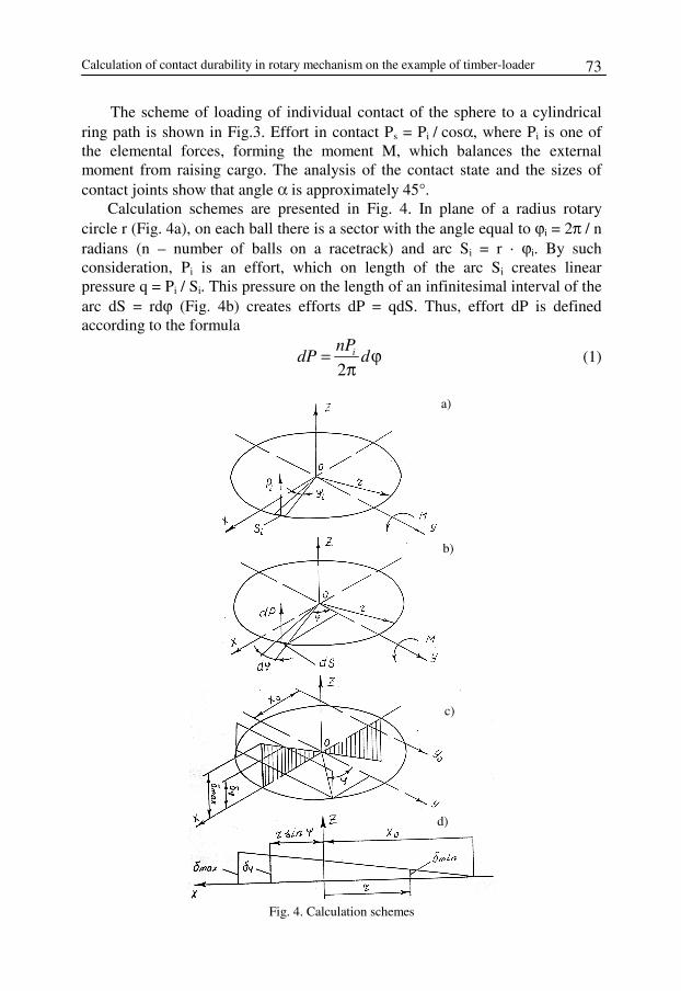
The scheme of loading of individual contact of the sphere to a cylindrical ring path is shown in Fig.3. Effort in contact Ps = Pi / cosα, where Pi is one of the elemental forces, forming the moment M, which balances the external moment from raising cargo. The analysis of the contact state and the sizes of contact joints show that angle α is approximately 45°.
Calculation schemes are presented in Fig. 4. In plane of a radius rotary circle r (Fig. 4a), on each ball there is a sector with the angle equal to ϕi = 2π / n radians (n – number of balls on a racetrack) and arc Si = r ⋅ ϕi. By such consideration, Pi is an effort, which on length of the arc Si creates linear pressure q = Pi / Si. This pressure on the length of an infinitesimal interval of the arc dS = rdϕ (Fig. 4b) creates efforts dP = qdS. Thus, effort dP is defined according to the formula
2inP
dP d= ϕπ
(1)
Fig. 4. Calculation schemes
b)
c)
d)
a)

V.I. Maksak, T.V. Maksak
74
The equation of the balance of moments defined according to the Formula (1) at the axis of symmetry Y is as follows:
0
2 0yM M dMπ
= − =∑ ∫ ,
taking into account Formula (1) this equation is as follows:
0
sin 0i
nrM P d
π
− ϕ ϕ =π ∫ (2)
The value of force Pi depends on a ball arrangement on the racetrack, so it depends on an angle ϕ. Hence, the problem is statically indefinable and demands consideration of a picture of deformation interrelation. The picture of deformation interrelation is presented in Fig. 4c, where deformation δϕ on an axis Z is accepted directly proportional to co-ordinate X = r⋅sinϕ. Then the condition of interrelation of deformations is as follows:
max sinϕδ = δ ⋅ ϕ (3)
According to work [2] the tie between the effort Ps and deformation δs in contact of two curvilinear surfaces is as follows:
2
3s sA Pδ = ⋅ (4)
where, value A characterises the mechanical properties of material and the main curvatures of contacting surfaces.
In accordance with (3), for contact of balls with the racetrack, the equation of deformation interrelation will be written as follows:
max sins sϕδ = δ ϕ (5)
It is supposed that complex loading of contact occurs along the forming friction cone, some features of complex loading of contact are thus neglected, considered in work [3]. For the physical side of the problem, dependence (4) can be used in equation (5), which is as follows:
2 2
3 3max sins sP Pϕ = ⋅ ϕ
Hence 3
2max sins sP Pϕ = ⋅ ϕ (6)
Taking into account (6) and dependencies Psϕ = Pi / cos α, we get:
3
2max0,707 sini sP P= ϕ (7)
Calculation of contact durability in rotary mechanism on the example of timber-loader 75
After substitution of PI, according to formula (7) equation (2) is as follows:
5max 2
0
0,707sin 0sn rP
M dπ⋅− ϕ ϕ =
π ∫
From this equation, the effort of the maximum loaded ball in contact with the racetrack is defined as follows:
max
6,168s
MP
nr= (8)
Knowing the effort of a maximum loaded ball, according to formulas of contact interaction of curvilinear bodies, it is possible to define the greatest pressure between the adjoining maximum loaded bodies. Comparing the received pressure with the supposed one, it is possible to define the maximum value Mmax of the cargo moment.
In the considered decision, one can assumed that cargo F insignificantly influences the rotary mechanism in comparison with the value of moment at the boom-out position. This working position of the lifting mechanism is the most dangerous to the rotary device. Indirectly, it is confirmed by an example of beam on two supports with a span equal to the diameter of a racetrack and loaded in the middle of span by the moment M = F ⋅ l. If in the middle of span the concentrated cross-section force is added, then at l = lmax, the value of support reactions will be changed only by 2 %.
At small values of boom-out position and considerable cargo F, the influence of the latter becomes more essential. At force F, the axis Y0 (Fig. 4c) of a turn in the XOZ plane of the loaded holders does not coincide with the axis of ordinates. At decreasing the boom position, the Y0 axis moves towards negative values of the X-axis. In a case when x0 > r, the balls of the top holder are compressed on all contact paths. Thus, the condition of the interrelation of deformations (3) is as follows:
minmax min
2 sinr r rϕδ − δδ − δ =+ ⋅ ϕ
(9)
The given scheme of the interrelation of deformations is shown in Fig. 4d in plane XOZ. Equation (9) contains two unknown values: maximum and minimum displacement. This condition demands an additional equation of the balance of forces:
2
0
02z i
nP F Pd
π
= − ϕ =π∑ ∫ (10)
The equation of the balance of moments is as follows:
2
0
sin2y i
nrM M P d
π
= − ϕ ϕπ∑ ∫ (11)

V.I. Maksak, T.V. Maksak
76
Solution of equations (8), (10) and (11), taking into account (8) and adopted previously statements allow one to determine effort Ps max in the contact of the maximum loaded ball.
Knowing the maximum efforts on a ball, one may determine the value of developing contact deformations on the racetrack.
The contact task of the contact of rigid ball with circle cylindrical surface of negative curvature was taken as a model task. The primary point of contact was taken as the beginning of coordinates. For each body, its own system of coordinates is defined. Let Z1 = F1(X1, Y1) is the equation of spherical surface, and its coordinate of centre is O1(O, O, R). Then, the equation of spherical surface is as follows:
2 2 2 2( )x y z R R+ + − =
As axes of coordinates in each system are registered with lines of the intersection of a tangent plane by planes of the main normal sections, then the main curvatures of the normal sections of the sphere at the beginning of coordinates are equal to the following:
2 21 1
11 122 21 10 0
, F F
k kx y
∂ ∂= =∂ ∂
where 2 2 21( , )F x y R R x y= ± − − , and sign (–) corresponds to the lower
contacting semicircle. Hence, the second particular derivative is as follows:
( ) ( )2 12
2 2 2 2 2 21 3 22
1
2
FR x y x R x y
x
− −∂ = − − − ⋅ + − −∂
(12)
Supposing that in formula (12) x = 0 and y = 0, we get
21
21 0
1
s
F
x R
∂ =∂
By analogy we find, that 2
121 0
1
s
F
y R
∂ =∂
The equation of cylindrical surface is as follows: ( )22 2s cx z R R+ + = , as
the axis of coordinates is directed along generating line of a cylinder and the centre of a cylinder section is displaced at a distance – Rc.
Calculation of contact durability in rotary mechanism on the example of timber-loader 77
The main curvatures of the cylindrical surfaces are equal to
2 22 2
21 222 22 20 0
1, 0
c
F Fk k
x R y
∂ ∂= = − = =∂ ∂
The equation of projection on the general tangent plane of the geometrical position of surface points of adjoining bodies describes an ellipse with coefficients [2]:
1 1 1 1,
2 2s s c
A BR R R
= = −
,
which is extended along the cross-section of cylinder. The sum of the main curvatures of adjoining bodies is equal to
2
1
2 c s
i s c
R Rk
R R=
−=⋅∑ (13)
Proceeding from rigid contact task [2], the values of the semicircles of the elliptical platform of contact is defined according to the following formulas:
12 3
12 3
3 1
2 2
3 1
2 2
s ca
c s
s cb
c s
R Ra n P
E R R
R Rb n P
E R R
∗
∗
∗
∗
⋅−µ= −
⋅−µ= −
Rapprochement and contact pressure are defined according to the following formulas:
12 32
2
12 2 3
2
29 10,5
4
21 3
2 1
c s
s c
c sq
s c
R Rn P
E R R
R R Eq n P
R R
∗
ω ∗
∗
∗
−−µω = ⋅ ⋅
− = π ⋅ −µ
The values of coefficients na, nb, nω, nq depend on quantity Ω, which was determined in work [2]:
( ) ( ) ( )( )1
2 2 211 12 21 22 11 12 21 22
12 cos 2k k k k k k k k
k Ω = − + − + − − ϕ ∑

V.I. Maksak, T.V. Maksak
78
According to the given theory, the calculation of the dependence of the contact module of elastic-plasticity for concrete work conditions of the rotary mechanism of timber-loader tower was carried out. Maximum loading on a ball calculated from formula (8) was 8.13 kH. The sum of main curvatures of interacting elements, a ball and a racetrack, calculated from formula (13) is equal to 0.66. Coefficients of an ellipse platform of contact interaction are A = 0,03125, B = 0,00185. The elastic constant for steel L50, from which the holders are made, is equal to 4.5⋅10–4 MPa. The numerical values of the factors entered into the expressions of semi-axes of an elliptic platform of contact with the greatest pressure and rapprochement of adjoining bodies for the relation B / A = 0.058 are defined in Table 14 in work [2] and are accordingly equal to: na = 2.975, nb = 0.4704, nq = 0.7144, nω = 0.6943.
The limit of fluidity of steel L50 is 340 MPa, the factor of linear hardening of a material is accepted as 4700 MPa.
The calculated dependence of contact module of elastic-plasticity CME – P for “a ball – a racetrack” contacting scheme is shown in Fig. 5.
Fig. 5. CME–P dependence from loading in scheme of contacting “a ball – a racetrack.” Letter (x) is the work condition defined in formula (8)
In this schedule, the points of the maximum contact pressure 8.13 kN, defined according to the formula (8) are marked. From the schedule, one can see that, at the maximum loading of the crane, the most loaded contact “a ball – a racetrack” is in a plastic condition and consequently the mechanism quickly loses its working capacity.
If in the scheme of loading (Fig. 3) α = 0, then the effort Ps max of the maximum loaded ball defined according to the formula (8) will be equal 5.75 kN, which also does not give a positive result.
The first site corresponds to elastic deformation, and the fourth site corresponds to the deformation at hardness change according to Brinell.
P = 8,13 кН
P, кN
Е*⋅104, МPа

Calculation of contact durability in rotary mechanism on the example of timber-loader 79
Results of calculations point to the necessity of carrying out the actions for the displacement of working conditions to the left on site 2. The increase of the contact module of elastic-plasticity can be provided by loading decrease and also by the design actions.
References
[1] Chernyscheva N.V., Maksak V.I. The contact of plastic elastic sphere with the rigid base under normal and tangential force. II International symposium of tribological problems. INSYCONT 1986. Materialy Proceedings. Krakow, Poland, 1986, p. 403-412.
[2] Calculation on durability in mechanical engineering.// Edited by Ponomarev, M., Mashgiz, V.2, 1968,
[3] Maksak V.I. Contact tasks in engineering and research practice. – Tomsk: Publishing House of TPU,1978. – 95p.
[4] Gipczyńska T., Pytko S.: Łożyska toczne wieńcowe. Wyd. AGH, 1999.
Manuscript received by Editorial Board, March 15th, 2010

V.E. Panarin, I.L. Oborskij
80