calculating factors of safety and margins of safety from ... · consequently margins of safety from...
TRANSCRIPT
John K. RamseyGlenn Research Center, Cleveland, Ohio
Calculating Factors of Safety and Margins ofSafety From Interaction Equations
NASA/TM—2019-220153
September 2019
https://ntrs.nasa.gov/search.jsp?R=20190032150 2020-06-10T00:09:27+00:00Z

NASA STI Program . . . in Profile
Since its founding, NASA has been dedicated to the advancement of aeronautics and space science. The NASA Scientific and Technical Information (STI) Program plays a key part in helping NASA maintain this important role.
The NASA STI Program operates under the auspices of the Agency Chief Information Officer. It collects, organizes, provides for archiving, and disseminates NASA’s STI. The NASA STI Program provides access to the NASA Technical Report Server—Registered (NTRS Reg) and NASA Technical Report Server—Public (NTRS) thus providing one of the largest collections of aeronautical and space science STI in the world. Results are published in both non-NASA channels and by NASA in the NASA STI Report Series, which includes the following report types:
• TECHNICAL PUBLICATION. Reports ofcompleted research or a major significant phaseof research that present the results of NASAprograms and include extensive data or theoreticalanalysis. Includes compilations of significantscientific and technical data and informationdeemed to be of continuing reference value.NASA counter-part of peer-reviewed formalprofessional papers, but has less stringentlimitations on manuscript length and extent ofgraphic presentations.
• TECHNICAL MEMORANDUM. Scientificand technical findings that are preliminary or ofspecialized interest, e.g., “quick-release” reports,working papers, and bibliographies that containminimal annotation. Does not contain extensiveanalysis.
• CONTRACTOR REPORT. Scientific andtechnical findings by NASA-sponsoredcontractors and grantees.
• CONFERENCE PUBLICATION. Collectedpapers from scientific and technicalconferences, symposia, seminars, or othermeetings sponsored or co-sponsored by NASA.
• SPECIAL PUBLICATION. Scientific,technical, or historical information fromNASA programs, projects, and missions, oftenconcerned with subjects having substantialpublic interest.
• TECHNICAL TRANSLATION. English-language translations of foreign scientific andtechnical material pertinent to NASA’s mission.
For more information about the NASA STI program, see the following:
• Access the NASA STI program home page athttp://www.sti.nasa.gov
• E-mail your question to [email protected]
• Fax your question to the NASA STIInformation Desk at 757-864-6500
• Telephone the NASA STI Information Desk at757-864-9658
• Write to:NASA STI ProgramMail Stop 148NASA Langley Research CenterHampton, VA 23681-2199
John K. RamseyGlenn Research Center, Cleveland, Ohio
Calculating Factors of Safety and Margins ofSafety From Interaction Equations
NASA/TM—2019-220153
September 2019
National Aeronautics andSpace Administration
Glenn Research Center Cleveland, Ohio 44135
Available from
Level of Review: This material has been technically reviewed by technical management.
NASA STI ProgramMail Stop 148NASA Langley Research CenterHampton, VA 23681-2199
National Technical Information Service5285 Port Royal RoadSpringfield, VA 22161
703-605-6000
This report is available in electronic form at http://www.sti.nasa.gov/ and http://ntrs.nasa.gov/
NASA/TM—2019-220153 1
Calculating Factors of Safety and Margins of Safety From Interaction Equations
John K. Ramsey
National Aeronautics and Space Administration Glenn Research Center Cleveland, Ohio 44135
Summary This report presents the derivation of the relationship between the factor of safety, the margin of
safety, and a given interaction equation in two- or three-dimensional space. Factors of safety and margins of safety can be calculated from these interaction equations using either the closed-form solutions provided or the numerical methods mentioned in this report. The dual definition of the factor of safety is presented.
Introduction For structures under combined loading, interaction equations have been used to predict structural
failure without having to determine the principal stresses. The interaction equations account for the simultaneous effect of one stress (or load, or moment) component on another, for all possible component stress (or load, or moment) combinations.
In aerospace engineering, margins of safety are used to indicate the strength capability remaining in a structure. This report presents closed-form solutions of, and methods to determine, factors of safety and consequently margins of safety from interaction equations.
Nomenclature
a exponent in interaction equation b exponent in interaction equation C1,2,3 constants in Equations (11) to (16) representing trigonometric functions for a given stress state
(cf. Figure 1)
c exponent in interaction equation F allowable stress FS factor of safety, definition 1. Calculated ratio S2/S1. See Appendix A. Fsu allowable ultimate shear stress Fsy allowable yield shear stress Ftu allowable tensile ultimate stress Fty allowable tensile yield stress f calculated stress factor of safety, definition 2. Specified multiplying factor applied to calculated stresses (or
corresponding calculated loads and or moments) for the purpose of creating a margin of safety. See Appendix A.
u ultimate factor of safety, definition 2. A specified multiplying factor applied to calculated stresses for the purpose of creating a margin of safety for the ultimate failure mode. See Appendix A.

NASA/TM—2019-220153 2
y yield factor of safety, definition 2. A specified multiplying factor applied to calculated stresses for the purpose of creating a margin of safety for the yield failure mode. See Appendix A.
MS margin of safety. A measure of a structure’s predicted reserve strength in excess of the product of the load or stress under consideration and the applicable factor of safety (definition 2 of factor of safety)
MSu margin of safety for the tensile, compressive, or shear ultimate condition MSy margin of safety for the tensile, compressive, or shear yield condition P point in stress-ratio space that is interior to the failure surface or failure curve P′ point in stress-ratio space on the failure surface or failure curve R stress ratio, f /F or () f / F Rb bending stress ratio Rs shear stress ratio
Rsu shear stress ratio for the ultimate condition Rsy shear stress ratio for the yield condition Rt tensile stress ratio Rtu tensile stress ratio for the ultimate condition Rty tensile stress ratio for the yield condition S1 magnitude of stress state corresponding to point P, interior to the failure surface in stress-ratio
space. See Figure 1 and Figure 4 to Figure 9. S2 magnitude of stress state corresponding to point P′ on the failure surface in stress-ratio space. See
Figure 1 and Figure 4 to Figure 9. SF safety factor, used synonymously for the factor of safety definition 2 () α angle defined in Figure 1 ∆ distance between points P′ and P φ angle defined in Figure 1 ( )′ quantity at structural failure ( )i,j,k indices representing different stress types, stress states, or failure modes
Stress Ratios Interaction equations characterize combinations of stress, loads, or moments that cause structural
failure (Refs. 1 to 7). These equations have been expressed in terms of load ratios, moment ratios, or stress ratios, where these ratios consist of loads, moments, or stresses of the same character. These interaction equations manifest themselves in the form of two-dimensional (2D) curves, three-dimensional (3D) surfaces, or boundaries in multidimensional space, and they can be created using theory (e.g., Ref. 3) or experiment (e.g., Ref. 1).
Reference 7 is one of the earlier publications describing the use of interaction equations to determine the allowable loads for a structure under combined loading. The approach was denoted therein as the “stress-ratio method.” In this report, stress ratios will be used exclusively. However, the same outcomes would result when using load or moment ratios. The stress ratio R, consisting of stresses of the same character is defined as
fRF
= (1)
where f is the calculated stress and F is the allowable stress.
NASA/TM—2019-220153 3
The factor of safety1 () can be incorporated into the stress ratios, and in those cases f is multiplied by the in the numerator of the stress ratio. Here is used to indicate a specified quantity, not to be confused by FS, which is a calculated quantity. Incorporating the into Equation (1), the stress ratio takes on the following general form:
( ) fR
F=
(2)
The ratio takes on the following form for the yield stress condition:
( )yty
ty
fR
F=
(3)
where y is the specified yield factor of safety, and Fty is the yield tensile stress allowable. A similar ratio can be constructed for the ultimate stress condition:
( )utu
tu
fR
F=
(4)
where u is the specified ultimate factor of safety, and Ftu is the ultimate tensile stress allowable. When a stress state involves shear, the following shear stress ratio for the yield condition is
customarily expressed as
( )y
sysy
fR
F=
(5)
where Fsy is the yield shear stress allowable.2 The shear stress ratio for the ultimate condition is customarily expressed as
( )usu
su
fR
F=
(6)
where Fsu is the ultimate shear stress allowable.2
1The use of the “factor of safety” terminology can be confusing because it has a dual definition. The different symbols FS and , corresponding to the two different definitions of the factor of safety, are used in this report for clarity, although this is typically not done in practice. Please see the definitions in the Nomenclature and Appendix A. 2If the yield or ultimate shear stress allowables are not available in the literature, it is customary to approximate the yield allowables as Fsy = 0.6Fty for alloy or carbon steels, and Fsy = 0.55Fty for stainless steels, and the ultimate allowables as Fsu = 0.6Ftu for alloy or carbon steels, and Fsu = 0.55Ftu for stainless steels (Ref. 6).
NASA/TM—2019-220153 4
Interaction Equations The interaction of one stress ratio with another at failure can be characterized using an interaction
equation expressed as
( ) ( ) ( ) 1 for ba c
i j kR R R i j k′ ′ ′Σ + Σ + Σ = ≠ ≠ (7)
where the exponents a, b, and c are determined from experimental test results as demonstrated, for example, in Reference 1 and/or theory as demonstrated in Reference 3. The stress ratios iR′ , jR′ , and kR′ characterize the failure stress state and do not include the specified because doing so would not truly reflect a failure stress state (unless = 1). The summations and corresponding indices permit the combination of stress ratios as dictated by experiment or theory. With the inclusion of three separate summations, Equation (7) is more general than typically encountered, but the intent is to address some possible as-yet-to-be-encountered interaction equations. Any stress combinations not covered by Equation (7) can be addressed using and extending the techniques presented in this report.
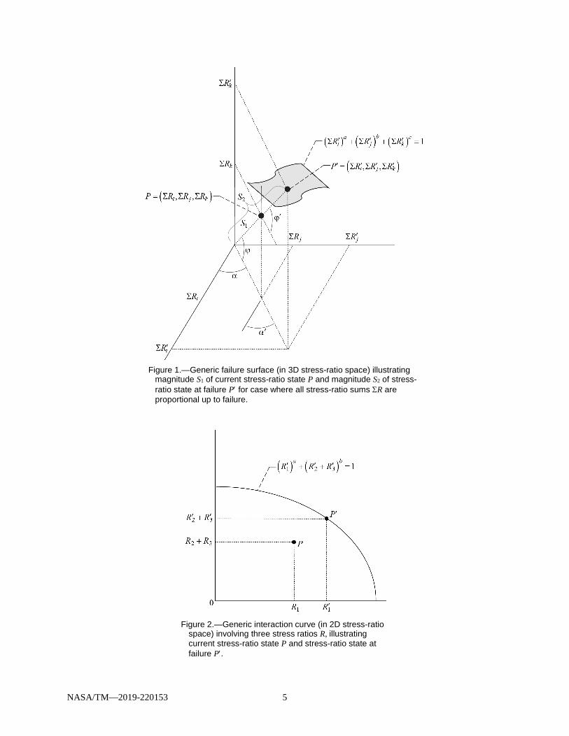
Equation (7) may be plotted as a surface in 3D stress-ratio space as shown schematically in Figure 1. This surface is sometimes referred to as a “failure surface,” or it could be described as an interaction surface. Some interaction equations involve three stress ratios, with two of them being summed together, and in these situations Equation (7) can be plotted in 2D stress-ratio space as shown in Figure 2, where typically one would only encounter two stress ratios. It is up to the discretion of the analyst to decide which axes represent a given stress ratio or sum of stress ratios. Figure 3 is a plot of a generic interaction equation with two stress ratios.
Referring to Figure 1, the stress state at point P has coordinates (ΣRi, ΣRj, and ΣRk), and it lies within the bounds of the failure (or interaction) surface (or equation), which indicates that the structure has reserve strength. The stress state at point P′ has coordinates ( iR′Σ , jR′Σ , and kR′Σ ) and lies on the failure (or interaction) surface, indicating that the structure does not have reserve strength at point P′.
Figure 2 shows a plot of interaction Equation (7), where the indices i = 1 and j = 2, 3 and where kR′ = 0. The stress state at point P has coordinates (R1, R2 + R3) and it lies within the bounds of the
interaction equation, which indicates that the structure has reserve strength. The stress state at point P′ has coordinates ( 1R′ , 2R′ + 3R′ ) and lies on the interaction curve, indicating that the structure has no reserve strength at point P′.
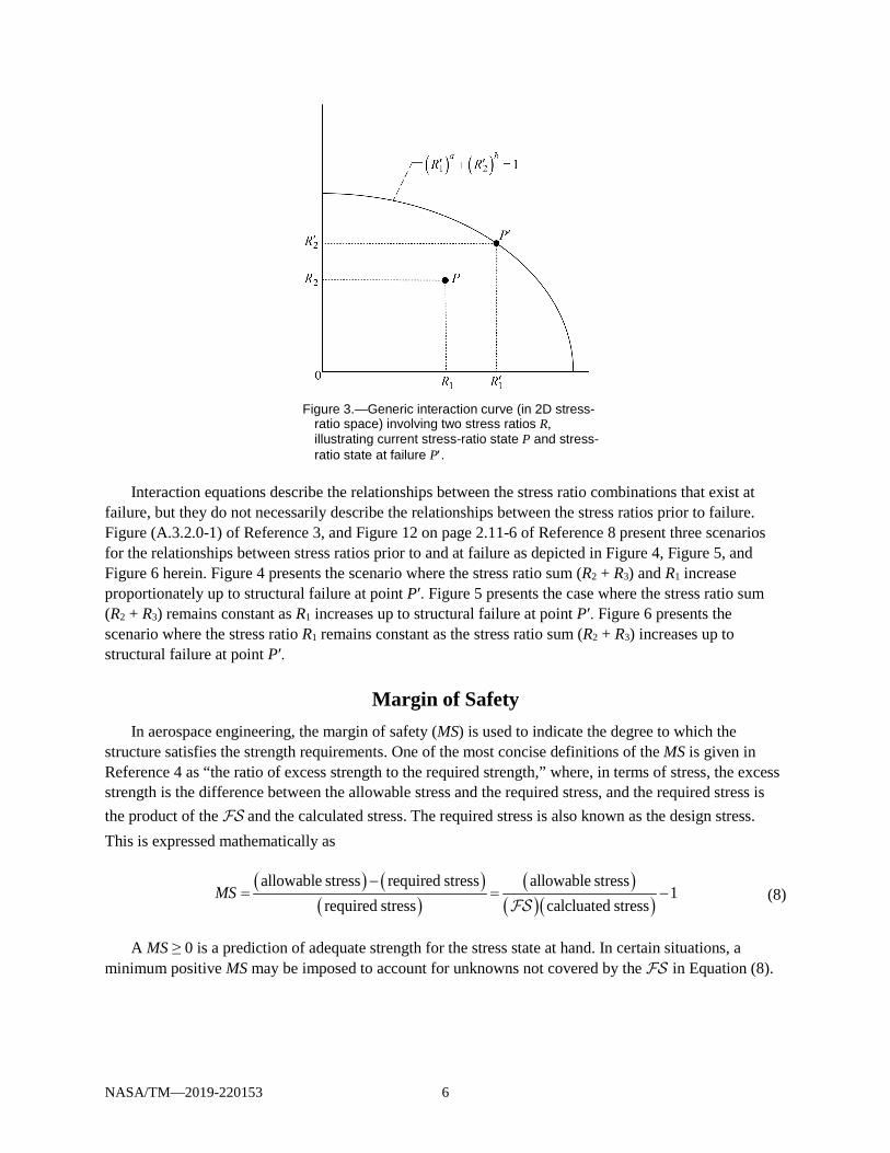
Figure 3 shows a generic plot of interaction Equation (7) involving two stress ratios, where i = 1 and j = 2 and where kR′ = 0. The stress state at point P has coordinates (R1, R2) and just as in the case for Figure 2, it lies within the bounds of the interaction equation, which indicates that the structure has reserve strength. The stress state at point P′ has coordinates ( 1R′ , 2R′ ) and lies on the interaction curve, indicating that the structure has no reserve strength at point P′.
NASA/TM—2019-220153 5
Figure 1.—Generic failure surface (in 3D stress-ratio space) illustrating
magnitude S1 of current stress-ratio state P and magnitude S2 of stress-ratio state at failure P′ for case where all stress-ratio sums ΣR are proportional up to failure.
Figure 2.—Generic interaction curve (in 2D stress-ratio
space) involving three stress ratios R, illustrating current stress-ratio state P and stress-ratio state at failure P′.
NASA/TM—2019-220153 6
Figure 3.—Generic interaction curve (in 2D stress-
ratio space) involving two stress ratios R, illustrating current stress-ratio state P and stress-ratio state at failure P′.
Interaction equations describe the relationships between the stress ratio combinations that exist at
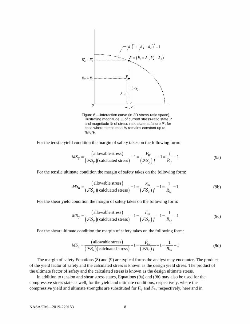
failure, but they do not necessarily describe the relationships between the stress ratios prior to failure. Figure (A.3.2.0-1) of Reference 3, and Figure 12 on page 2.11-6 of Reference 8 present three scenarios for the relationships between stress ratios prior to and at failure as depicted in Figure 4, Figure 5, and Figure 6 herein. Figure 4 presents the scenario where the stress ratio sum (R2 + R3) and R1 increase proportionately up to structural failure at point P′. Figure 5 presents the case where the stress ratio sum (R2 + R3) remains constant as R1 increases up to structural failure at point P′. Figure 6 presents the scenario where the stress ratio R1 remains constant as the stress ratio sum (R2 + R3) increases up to structural failure at point P′.
Margin of Safety In aerospace engineering, the margin of safety (MS) is used to indicate the degree to which the
structure satisfies the strength requirements. One of the most concise definitions of the MS is given in Reference 4 as “the ratio of excess strength to the required strength,” where, in terms of stress, the excess strength is the difference between the allowable stress and the required stress, and the required stress is the product of the and the calculated stress. The required stress is also known as the design stress. This is expressed mathematically as
( ) ( )
( )( )
( )( )allowable stress required stress allowable stress
1required stress calcluated stress
MS−
= = −
(8)
A MS ≥ 0 is a prediction of adequate strength for the stress state at hand. In certain situations, a minimum positive MS may be imposed to account for unknowns not covered by the in Equation (8).

NASA/TM—2019-220153 7
Figure 4.—Interaction curve (in 2D stress-ratio space)
involving three stress ratios R, illustrating magnitude S1 of current stress-ratio state P and magnitude S2 of stress-ratio state at failure P′, for case where stress ratio R1 is proportional to stress ratio sum (R2 + R3) up to failure.
Figure 5.—Interaction curve (in 2D stress-ratio space), illustrating magnitude S1
of current stress-ratio state P and magnitude S2 of stress-ratio state at failure P′, for case where stress ratio sum (R2 + R3) remains constant up to failure.
NASA/TM—2019-220153 8
Figure 6.—Interaction curve (in 2D stress-ratio space),
illustrating magnitude S1 of current stress-ratio state P and magnitude S2 of stress-ratio state at failure P′, for case where stress ratio R1 remains constant up to failure.
For the tensile yield condition the margin of safety takes on the following form:
( )( )( ) ( )
allowable stress 11 1 1calcluated stress
tyy
tyy y
FMS
Rf= − = − = −
(9a)
For the tensile ultimate condition the margin of safety takes on the following form:
( )
( )( ) ( )allowable stress 11 1 1
calcluated stresstu
uu u tu
FMSf R
= − = − = −
(9b)
For the shear yield condition the margin of safety takes on the following form:
( )( )( ) ( )
allowable stress 11 1 1calcluated stress
syy
syy y
FMS
Rf= − = − = −
(9c)
For the shear ultimate condition the margin of safety takes on the following form:
( )( )( ) ( )
allowable stress 11 1 1calcluated stress
suu
u u su
FMSf R
= − = − = −
(9d)
The margin of safety Equations (8) and (9) are typical forms the analyst may encounter. The product of the yield factor of safety and the calculated stress is known as the design yield stress. The product of the ultimate factor of safety and the calculated stress is known as the design ultimate stress.
In addition to tension and shear stress states, Equations (9a) and (9b) may also be used for the compressive stress state as well, for the yield and ultimate conditions, respectively, where the compressive yield and ultimate strengths are substituted for Fty and Ftu, respectively, here and in

NASA/TM—2019-220153 9
Equations (3) and (4). The above equations assume that the yield factor of safety (definition 2) applies to the tensile, compressive, or shear yield condition, and that the ultimate factor of safety (definition 2) applies to the tensile, compressive, or shear ultimate condition.
Reference 5 presents interaction equations for combined load systems and their corresponding MS equations, but it does not explicitly show how to obtain the MS equation from its corresponding interaction equation. Reference 2 presents the MS equation and the interaction equation in terms of a common factor in 2D stress-ratio space, creating a system of two equations and two unknowns that can be solved for the common factor and consequently, the MS. Reference 9 extends the coverage of the MS topic presented in Reference 5, illustrating this same system of two equations and two unknowns, but extending the presentation in Reference 2 to that of a multidimensional stress-ratio space. One feature of the current report is to present the derivation of the system of two equations with the common factor.
Referring to Figure 1 to Figure 6, the allowable stress combination corresponds to point P′, and the required stress combination corresponds to point P, and Equation (8) becomes
P PMSP′ −
= (10)
Referring to Figure 1, the following relationships may be observed:
1 1 1cos cos i iS R S C Rϕ α = Σ → = Σ (11)
1 1 2cos sin j jS R S C Rϕ α = Σ → = Σ (12)
1 1 3sin k kS R S C Rϕ = Σ → = Σ (13)
2 2 1cos cos i iS R S C R′ ′ϕ α = Σ → = Σ (14)
2 2 2cos sin j jS R S C R′ ′ϕ α = Σ → = Σ (15)
2 2 3sin k kS R S C R′ ′ϕ = Σ → = Σ (16)
where the trigonometric terms are constants for a given stress state, and for conciseness these are denoted as C1, C2, and C3 as shown above.
Although the following mathematics leading up to Equation (21) could have been omitted here, by inspection of Figure 1, it was decided to be more rigorous. Utilizing the equations for the distance between two points in 3D space, the ratio in Equation (10) becomes
( ) ( ) ( )
( ) ( ) ( )
22 2
22 20 0 0
i i j j k k
i j k
R R R R R RP PP R R R
′ ′ ′Σ − Σ + Σ − Σ + Σ −Σ′ −=
Σ − + Σ − + Σ − (17)
Substituting Equations (11) to (16) into Equation (17) gives
( ) ( ) ( )
( ) ( ) ( )
2 2 22 1 1 1 2 2 1 2 2 3 1 3
2 2 21 1 1 2 1 3
S C S C S C S C S C S CP PP S C S C S C
− + − + −′ −=
+ + (18)
NASA/TM—2019-220153 10
Factoring out terms in Equation (18) yields
( ) ( )
( )
2 2 2 22 1 1 2 3
2 2 2 21 1 2 3
S S C C CP PP S C C C
− + +′ −=
+ + (19)
Rearranging Equation (19) simplifies to
( ) ( )
( )
2 2 22 1 1 2 3 2 1
2 2 2 11 1 2 3
S S C C CP P S SP SS C C C
− + +′ − −= =
+ + (20)
Substituting Equation (20) into Equation (10), the MS becomes
2 1 2
1 11S S SMS
S S−
= = − (21)
As can be seen from Equation (21), the MS is expressed in terms of the distances S1 and S2 as defined in Figure 1, Figure 4, Figure 5, and Figure 6.
Factor of Safety Reference 3 employs both definitions (mentioned previously) of the factor of safety. In regard to
interaction equations, and in terms of variables used in this report, Reference 3 defines the factor of safety to be the calculated ratio of S2 to S1. The factor of safety in this regard will be denoted as FS, thus differentiating it from the specified factor of safety, . Therefore,
2
1
SFSS
= (22a)
It should be noted as mentioned previously, that on the interaction curve or surface, the stress ratios do not incorporate the specified (or equivalently could be thought of as equaling 1 there). Therefore S2, which lies on the interaction curve or surface and is a function of stress ratios per Equations (14) to (16), does not incorporate a . However, because S1 is not on the interaction or failure surface and is a function of stress ratios per Equations (11) to (13), it may incorporate a . This is shown symbolically in Equation (22b), where the subscript indices i could be replaced with index j or k. The derivation of Equation (22b) is presented in Appendix A.
( )
2
1
i
i
ii
i
fS FFS
fSF
′
= =∑
∑
(22b)
Equation (22b) shows that the factor of safety definition 1 is a function of the factor of safety definition 2. To avoid confusion between the factor of safety symbols in Equation (22b), the terminology

NASA/TM—2019-220153 11
“safety factor” (SF) may be employed in place of the factor of safety () definition 2. Please see Appendix A for a more detailed presentation on this.
Substituting Equation (22a) into Equation (21) gives the margin of safety in terms of the factor of safety (definition 1):
1MS FS= − (23)
Again, it can be seen from comparing Equation (23) with Equation (8) that the FS is a function of .
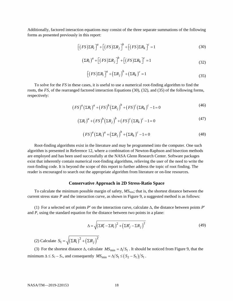
Interaction Surfaces In the following mathematical development through Equation (30), the stress ratios are assumed to be
proportional to each other. This means that ϕ′ = ϕ and α′ = α in Figure 1. Multiplying both sides of Equation (22a) by cos ϕ cos α and rearranging gives
( ) 1 2cos cos cos cosFS S Sϕ α = ϕ α (24)
and upon substituting Equations (11) and (14) into Equation (24),
( ) i iFS R R′Σ = Σ (25)
Multiplying both sides of Equation (22a) by cos ϕ sin α and rearranging leads to
( ) 1 2cos sin cos sinFS S Sϕ α = ϕ α (26)
and upon substituting Equations (12) and (15) into Equation (26),
( ) j jFS R R′Σ = Σ (27)
Multiplying both sides of Equation (22a) by sin ϕ and rearranging gives
( ) 1 2sin sinFS S Sϕ = ϕ (28)
and upon substituting Equations (13) and (16) into Equation (28),
( ) k kFS R R′Σ = Σ (29)
Substituting Equations (25), (27), and (29) into Equation (7) generates Equation (30), which describes the relationships between stress ratios in terms of the FS for the scenario that all stress ratios maintain proportionality prior to and at failure.
( ) ( ) ( ) 1ba c
i j kFS R FS R FS R Σ + Σ + Σ = (30)
Equation (30) is valid for all failure surfaces in 3D space, including exponents with noninteger values, and corresponds to the failure path from S1 to S2 shown in Figure 1. This type of equation describing the relationships between the stress ratios prior to, and at failure, in terms of the factor of safety FS will be denoted from here on as the “factored interaction equation.”
NASA/TM—2019-220153 12
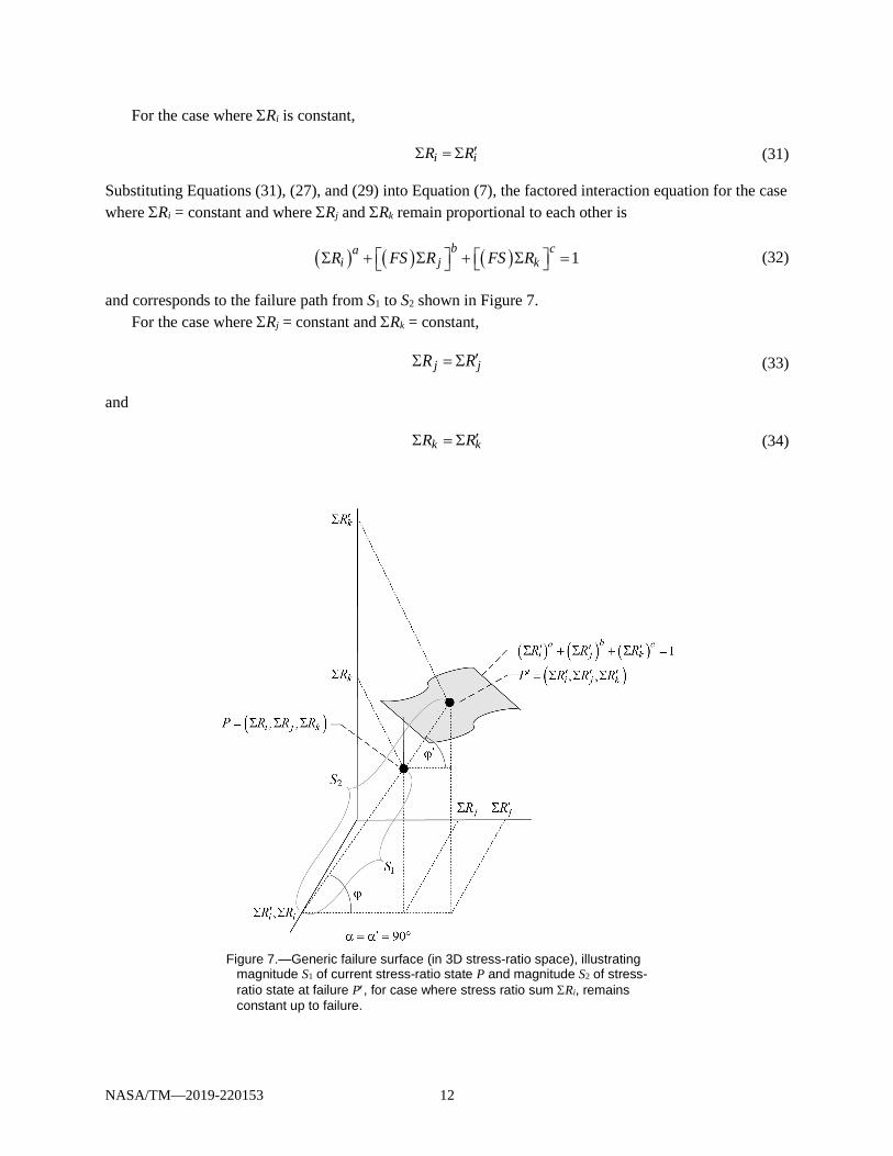
For the case where ΣRi is constant,
i iR R′Σ = Σ (31)
Substituting Equations (31), (27), and (29) into Equation (7), the factored interaction equation for the case where ΣRi = constant and where ΣRj and ΣRk remain proportional to each other is
( ) ( ) ( ) 1b ca
i j kR FS R FS R Σ + Σ + Σ = (32)
and corresponds to the failure path from S1 to S2 shown in Figure 7. For the case where ΣRj = constant and ΣRk = constant,
j jR R′Σ = Σ (33)
and
k kR R′Σ = Σ (34)
Figure 7.—Generic failure surface (in 3D stress-ratio space), illustrating
magnitude S1 of current stress-ratio state P and magnitude S2 of stress-ratio state at failure P′, for case where stress ratio sum ΣRi, remains constant up to failure.
NASA/TM—2019-220153 13
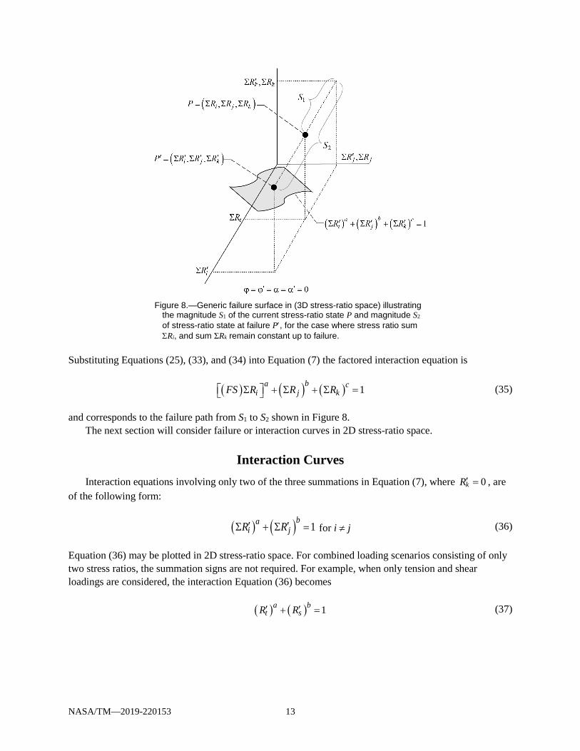
Figure 8.—Generic failure surface in (3D stress-ratio space) illustrating
the magnitude S1 of the current stress-ratio state P and magnitude S2 of stress-ratio state at failure P′, for the case where stress ratio sum ΣRi, and sum ΣRk remain constant up to failure.
Substituting Equations (25), (33), and (34) into Equation (7) the factored interaction equation is
( ) ( ) ( ) 1ba c
i j kFS R R R Σ + Σ + Σ = (35)
and corresponds to the failure path from S1 to S2 shown in Figure 8. The next section will consider failure or interaction curves in 2D stress-ratio space.
Interaction Curves Interaction equations involving only two of the three summations in Equation (7), where 0kR′ = , are
of the following form:
( ) ( ) 1ba
i jR R′ ′Σ + Σ = for i ≠ j (36)
Equation (36) may be plotted in 2D stress-ratio space. For combined loading scenarios consisting of only two stress ratios, the summation signs are not required. For example, when only tension and shear loadings are considered, the interaction Equation (36) becomes
( ) ( ) 1a bt sR R′ ′+ = (37)
NASA/TM—2019-220153 14
Equation (36) is also often used for the case where tension, bending, and shear are considered for beam-like structures, in which case the interaction Equation (36) often is of the form
( ) ( ) 1a bt b sR R R′ ′ ′+ + = (38)
where the first summation in Equation (36) is utilized, since the tension and bending stress act normal to the structural cross section, and thus the tension and bending stress ratios being of similar character may be added. For the case where both stress ratio sums are proportional to each other we substitute Equations (25) and (27) into Equation (36), yielding the factored interaction equation
( ) ( ) 1ba
i jFS R FS R Σ + Σ = (39)
which could have also been obtained by deleting the last term on the left hand side of Equation (30). For the case where one of the stress ratio sums remains constant up to failure, for example when ΣRj
is constant, then
j jR R′Σ = Σ (40)
Substituting Equation (40) and Equation (25) into Equation (36) yields the factored interaction equation for the case where ΣRj is constant,
( ) ( ) 1ba
i jFS R R Σ + Σ = (41)
which could have also been obtained be deleting the last terms on the left hand side of Equation (35). Equation (41) is equivalent in form to the case where ΣRi is constant, which is
( ) ( ) 1ba
i jR FS R Σ + Σ = (42)
For the rest of this report, Equation (41) will be used to cover 2D factored interaction equations for the scenarios when one stress ratio sum remains constant up to failure.
Calculating the Factor of Safety and Consequently the Margin of Safety Equations (30), (32), (35), (39), or (41) individually and Equation (23) constitute a system of two
equations and two unknowns (FS and MS) that may be solved for the FS and subsequently the MS. The FS may be determined from factored interaction Equations (30), (32), (35), (39), or (41),
knowing the exponents a, b, and c and the stress ratios, Ri, Rj, and Rk. Once the FS is obtained, the MS may be calculated using Equation (23).

NASA/TM—2019-220153 15
In many cases a closed-form solution for the FS may be obtained directly or by using an analytical approach such as Cardano’s Method3 (Ref. 10) for equations up to order 3, which is outlined here. Table I to Table III provide these closed-form solutions for the FS as well as the constants used in Cardano’s Method for interaction equations of the forms of Equations (30), (32), and (35). By subtracting 1 from the FS, the MS is obtained, as shown in Equation (23). Appendix B, Appendix C, and Appendix D present the derivations of the closed-form solutions presented in the tables along with the constants used in Cardano’s Method.
To implement Cardano’s Method, transform the factored interaction equation into the form
( ) ( ) ( )3 2 0FS d FS e FS g+ + + = (43)
Equation (43) may be solved for the factor of safety FS using Cardano’s Method as follows:
1. Calculate 2
3dp e= − +
2. Calculate 3
23 3d deq g = − +
3. Calculate 3 2
3 2p qQ = +
4. Calculate 32qA Q= − +
5. Calculate 32qB Q= − −
6. Calculate 1 A By = +
7. Calculate 2,3 32 2
A B A Biy + −= − ±
8. Calculate the factors of safety (roots): ( ) 3iiFS y d= − , where the (FS)i must be a real number
9. Calculate the minimum MS, ( )min 1iMS FS = −
3Sometimes referred to in English as Cardan’s Method.
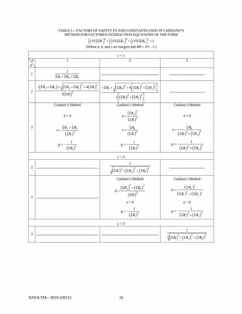
NASA/TM—2019-220153 16
TABLE I.—FACTORS OF SAFETY FS AND CONSTANTS USED IN CARDANO’S METHOD FOR FACTORED INTERACTION EQUATIONS OF THE FORM
( ) ( ) ( ) 1a b c
i j kFS R FS R FS R Σ + Σ + Σ =
[Where a, b, and c are integers and MS = FS – 1.]
c = 1 b a
1 2 3
1 1
i j kR R RΣ + Σ + Σ ------------------------------------------------ ------------------------------
2 ( ) ( ) ( )
( )
2 2
2
4
2
j k j k i
i
R R R R R
R
− Σ + Σ + Σ + Σ + Σ
Σ
( ) ( ) ( )
( ) ( )
22 2
22
4
2
k k i j
i j
R R R R
R R
−Σ + Σ + Σ + Σ Σ + Σ
------------------------------
3
Cardano’s Method Cardano’s Method Cardano’s Method
d = 0 ( )( )
2
3j
i
Rd
R
Σ=
Σ d = 0
( )3j k
i
R Re
R
Σ + Σ=
Σ
( )3k
i
ReRΣ
=Σ
( ) ( )33
k
i j
ReR R
Σ=
Σ + Σ
( )31
i
gR
= −Σ
( )3
1
i
gR
= −Σ
( ) ( )33
1
i j
gR R
= −Σ + Σ
c = 2
2 ---------------------------------------------------- ( ) ( ) ( )22 2
1
i j kR R RΣ + Σ + Σ ------------------------------
3 ----------------------------------------------------
Cardano’s Method Cardano’s Method
( ) ( )( )
2 2
3j k
i
R Rd
R
Σ + Σ=
Σ
( )
( ) ( )
2
3 3
k
i j
Rd
R R
Σ=
Σ + Σ
e = 0 e = 0
( )31
i
gR
= −Σ
( ) ( )33
1
i j
gR R
= −Σ + Σ
c = 3
3 ---------------------------------------------------- ------------------------------------------------ ( ) ( ) ( )33 33
1
i j kR R RΣ + Σ + Σ

NASA/TM—2019-220153 17
TABLE II.—FACTORS OF SAFETY FS AND CONSTANTS USED IN CARDANO’S METHOD FOR FACTORED INTERACTION EQUATIONS OF THE FORM
( ) ( ) ( ) 1b ca
i j kR FS R FS R Σ + Σ + Σ = [Where a, b, and c are integers and MS = FS – 1.]
c b
1 2 3
1 ( )1 a
i
j k
RR R− Σ
Σ + Σ ----------------------- ---------------------
2 ( ) ( ) ( )
( )
22
2
4 1
2
ak k j i
j
R R R R
R
−Σ + Σ + Σ − Σ
Σ
( )( ) ( )2 2
1 ai
j k
R
R R
− Σ
Σ + Σ ---------------------
3
Cardano’s Method Cardano’s Method
( )( ) ( )
3 3 3
1 ai
j k
R
R R
− Σ
Σ + Σ
d = 0 ( )( )
2
3k
j
Rd
R
Σ=
Σ
( )3k
j
ReR
Σ=
Σ e = 0
( )( )3
1ai
j
Rg
R
Σ −=
Σ ( )
( )31a
i
j
Rg
R
Σ −=
Σ
TABLE III.—FACTORS OF SAFETY FS FOR FACTORED
INTERACTION EQUATIONS OF THE FORM ( ) ( ) ( ) 1
ba ci j kFS R R R Σ + Σ + Σ =
[Where a, b, and c are integers and MS = FS – 1.]
( ) ( )1b c
j k
i
a R R
R
− Σ − Σ
Σ
Integer Exponents of Order 3 or Higher, or Noninteger Exponents
The previous sections presented closed-form solutions, including Cardano’s Method for equations up to order 3, for solving for the FS from the factored interaction Equations (30), (32), and (35) (shown again below), and subsequently the MS. Closed-form solutions also exist that can be used to solve for the FS when the factored interaction equation is of integer order 4. However, it is more useful to adopt a general numerical procedure to solve for the FS from the factored interaction equations of any order, including cases where the exponents are not integers, as shown in Equations (44) and (45) (interaction equations from Ref. 11), for example:
( ) ( )( )2.5 1.5 1s t bFS R FS R R + + = (44)
( ) ( ) ( )2.5 1.5 1s t bFS R FS R FS R + + = (45)
NASA/TM—2019-220153 18
Additionally, factored interaction equations may consist of the three separate summations of the following forms as presented previously in this report:
( ) ( ) ( ) 1ba c
i j kFS R FS R FS R Σ + Σ + Σ = (30)
( ) ( ) ( ) 1b ca
i j kR FS R FS R Σ + Σ + Σ = (32)
( ) ( ) ( ) 1ba c
i j kFS R R R Σ + Σ + Σ = (35)
To solve for the FS in these cases, it is useful to use a numerical root-finding algorithm to find the roots, the FS, of the rearranged factored interaction Equations (30), (32), and (35) of the following forms, respectively:
( ) ( ) ( ) ( ) ( ) ( ) 1 0ba a b c c
i j kFS R FS R FS RΣ + Σ + Σ − = (46)
( ) ( ) ( ) ( ) ( ) 1 0ba b c c
i j kR FS R FS RΣ + Σ + Σ − = (47)
( ) ( ) ( ) ( ) 1 0ba a c
i j kFS R R RΣ + Σ + Σ − = (48)
Root-finding algorithms exist in the literature and may be programmed into the computer. One such algorithm is presented in Reference 12, where a combination of Newton-Raphson and bisection methods are employed and has been used successfully at the NASA Glenn Research Center. Software packages exist that inherently contain numerical root-finding algorithms, relieving the user of the need to write the root-finding code. It is beyond the scope of this report to further address the topic of root finding. The reader is encouraged to search out the appropriate algorithm from literature or on-line resources.
Conservative Approach in 2D Stress-Ratio Space
To calculate the minimum possible margin of safety, MSmin; that is, the shortest distance between the current stress state P and the interaction curve, as shown in Figure 9, a suggested method is as follows:
(1) For a selected set of points P′ on the interaction curve, calculate ∆, the distance between points P′
and P, using the standard equation for the distance between two points in a plane:
( ) ( )22i i j jR R R R′ ′∆ = Σ − Σ + Σ −Σ (49)
(2) Calculate ( ) ( )221 i jS R R= Σ + Σ
(3) For the shortest distance ∆, calculate min 1MS S= ∆ . It should be noticed from Figure 9, that the
minimum ∆ ≤ S2 – S1, and consequently ( )min 1 2 1 1MS S S S S= ∆ ≤ − .

NASA/TM—2019-220153 19
Figure 9.—Conservative interpretation of margin
of safety (MS) (in 2D stress-ratio space), where MS = ∆/S1. Current stress-ratio state P and closest stress-ratio state at failure P′, are illustrated.
Conclusion This report derives the relationship between factors of safety and interaction equations, denoted as the
“factored interaction equation,” enabling the determination of the corresponding margins of safety. Factored interaction equations were considered for cases where all or some stress ratios remain proportional up to failure and the other stress ratios remain constant. Closed-form solutions including the constants used in Cardano’s Method, for the factor of safety and consequently the margin of safety, were presented in terms of stress ratios. Numerical root-finding methods are useful in situations where the interaction equations, and consequently the factored interaction equations, are of order 4 or higher, or they contain noninteger exponents.

NASA/TM—2019-220153 21
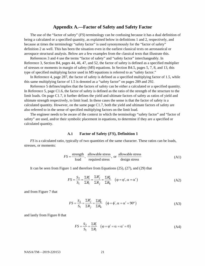
Appendix A.—Factor of Safety and Safety Factor The use of the “factor of safety” (FS) terminology can be confusing because it has a dual definition of
being a calculated or a specified quantity, as explained below in definitions 1 and 2, respectively, and because at times the terminology “safety factor” is used synonymously for the “factor of safety” definition 2 as well. This has been the situation even in the earliest classical texts on aeronautical or aerospace structural analysis. Below are a few examples from the classical texts that illustrate this.
References 3 and 4 use the terms “factor of safety” and “safety factor” interchangeably. In Reference 3, Section B4, pages 44, 46, 47, and 52, the factor of safety is defined as a specified multiplier of stresses or moments in margin of safety (MS) equations. In Section B4.5, pages 5, 7, 8, and 13, this type of specified multiplying factor used in MS equations is referred to as “safety factor.”
In Reference 4, page 287, the factor of safety is defined as a specified multiplying factor of 1.5, while this same multiplying factor of 1.5 is denoted as a “safety factor” on pages 289 and 292.
Reference 5 defines/implies that the factors of safety can be either a calculated or a specified quantity. In Reference 5, page C1.6, the factor of safety is defined as the ratio of the strength of the structure to the limit loads. On page C1.7, it further defines the yield and ultimate factors of safety as ratios of yield and ultimate strength respectively, to limit load. In these cases the sense is that the factor of safety is a calculated quantity. However, on the same page C1.7, both the yield and ultimate factors of safety are also referred to in the sense of specified multiplying factors on the limit load.
The engineer needs to be aware of the context in which the terminology “safety factor” and “factor of safety” are used, and/or their symbolic placement in equations, to determine if they are a specified or calculated quantity.
A.1 Factor of Safety (FS), Definition 1
FS is a calculated ratio, typically of two quantities of the same character. These ratios can be loads, stresses, or moments:
strength allowable stress allowable stress, , or load required stress design stress
FS = (A1)
It can be seen from Figure 1 and therefore from Equations (25), (27), and (29) that
( )2
1,ji k
i j k
RS R RFSS R R R
′Σ′ ′Σ Σ ′ ′= = = = ϕ = ϕ α = αΣ Σ Σ
(A2)
and from Figure 7 that
( )2
1, 90j k
j k
RS RFSS R R
′Σ ′Σ ′ ′= = = φ = φ α = α = °Σ Σ
(A3)
and lastly from Figure 8 that
( )2
10i
i
S RFSS R
′Σ ′ ′= = ϕ = ϕ = α = α =Σ
(A4)

NASA/TM—2019-220153 22
Substituting Equation (2) into Equations (A2) to (A4), and keeping in mind that the stress ratios on the interaction curve or surface R′ do not have a specified (or equivalently, could be thought of as equaling 1 there), the relationship between the calculated FS and the specified in terms of stress becomes
( )2
1
i
i
ii
i
fS FFS
fSF
′
= =∑
∑
(A5)
where the stress subscript indices i, could be replaced by j or k and where Equation (A5) is applicable to the stress states characterized by Equations (A2) to (A4).
If the allowable stress F and the specified factor of safety can be taken outside of the summation in Equation (A5), the factor of safety in its simplified form becomes
( ) ( ) ( )
2
1
1f f fS F FFSfS ff
F F
′′ ′
= = = =∑ ∑ ∑
∑∑ ∑ (A6)
If in some cases it is not permissible to take one or both of the stress F and the specified factor of safety outside of the summations, Equation (A5) can be simplified accordingly, but the fact remains that the calculated factor of safety is a function of the specified factor of safety.
The margin of safety may be expressed in terms of the calculated factor of safety as derived in the main text as Equation (23) and repeated here for completeness:
1MS FS= − (23)
A.2 Factor of Safety (), Definition 2
is a specified multiplying factor applied to loads or stresses for purposes of calculating margins of safety MS, and at times is referred to as a “safety factor”:
allowable stress 1( )calculated stress
MS = −
(A7a)
allowable load 1( )calculated load
MS = −
(A7b)
This definition of the is usually associated with yield and ultimate strengths or stresses; namely, the yield and ultimate factors of safety are often denoted symbolically as y and u, respectively.
NASA/TM—2019-220153 23
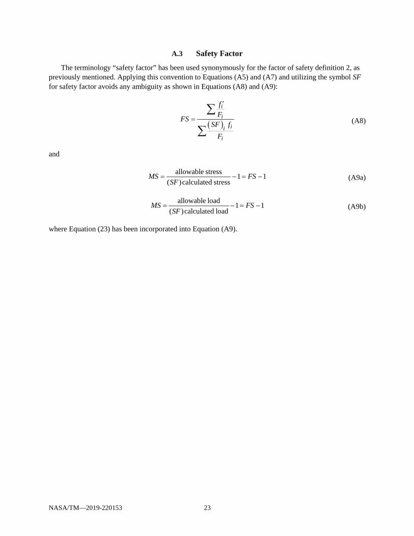
A.3 Safety Factor
The terminology “safety factor” has been used synonymously for the factor of safety definition 2, as previously mentioned. Applying this convention to Equations (A5) and (A7) and utilizing the symbol SF for safety factor avoids any ambiguity as shown in Equations (A8) and (A9):
( )
i
i
ii
i
fFFS
SF fF
′
=∑
∑ (A8)
and
allowable stress 1 1( )calculated stress
MS FSSF
= − = − (A9a)
allowable load 1 1( )calculated load
MS FSSF
= − = − (A9b)
where Equation (23) has been incorporated into Equation (A9).


NASA/TM—2019-220153 25
Appendix B.—Stress Ratios Maintaining Proportionality Up to Failure This appendix derives the closed-form equations for the factor of safety (FS) and consequently the
margin of safety (MS) for several examples of factored interaction equations in the form of Equation (30):
( ) ( ) ( ) 1ba c
i j kFS R FS R FS R Σ + Σ + Σ = (B1)
involving different integer exponent values (1, 2, or 3).
B.1 a = b = c = 1
The factored interaction Equation (B1) becomes
( ) ( ) ( )11 1 1i j kFS R FS R FS R Σ + Σ + Σ = (B2)
and after factoring out the factor of safety FS, it may be obtained directly:
1i j k
FSR R R
=Σ + Σ + Σ
(B3)
By substituting Equation (B3) into Equation (23), the MS is
1 1
i j kMS
R R R= −Σ + Σ + Σ
(B4)
B.2 a = 2, b = c = 1
The factored interaction Equation (B1) becomes
( ) ( ) ( )12 1 1i j kFS R FS R FS R Σ + Σ + Σ = (B5)
Rearranging Equation (B5) into a quadratic equation in FS,
( ) ( ) ( )( )2 2 1 0i j kR FS R R FSΣ + Σ + Σ − = (B6)
The FS may be obtained using the quadratic formula
( ) ( ) ( )
( )
2 2
2
4
2
j k j k i
i
R R R R RFS
R
− Σ + Σ + Σ + Σ + Σ=
Σ (B7)
where the negative square root in the numerator has been omitted because the FS must be positive. If you
multiply the numerator and denominator of Equation (B7) by ( ) ( ) ( )2 24j k j k iR R R R RΣ + Σ + Σ + Σ + Σ ,
the FS becomes
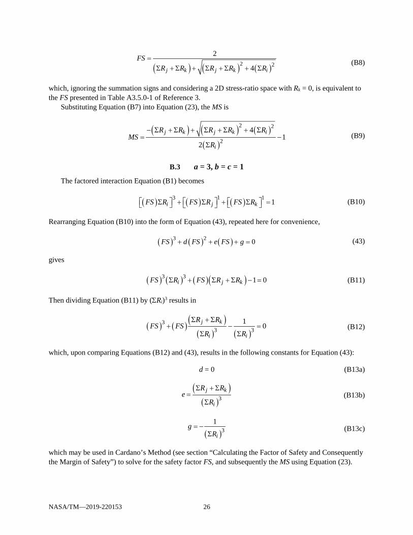
NASA/TM—2019-220153 26
( ) ( ) ( )2 2
2
4j k j k i
FSR R R R R
=Σ + Σ + Σ + Σ + Σ
(B8)
which, ignoring the summation signs and considering a 2D stress-ratio space with Rk = 0, is equivalent to the FS presented in Table A3.5.0-1 of Reference 3.
Substituting Equation (B7) into Equation (23), the MS is
( ) ( ) ( )
( )
2 2
2
41
2
j k j k i
i
R R R R RMS
R
− Σ + Σ + Σ + Σ + Σ= −
Σ (B9)
B.3 a = 3, b = c = 1
The factored interaction Equation (B1) becomes
( ) ( ) ( )13 1 1i j kFS R FS R FS R Σ + Σ + Σ = (B10)
Rearranging Equation (B10) into the form of Equation (43), repeated here for convenience,
( ) ( ) ( )3 2 0FS d FS e FS g+ + + = (43)
gives
( ) ( ) ( )( )3 3 1 0i j kFS R FS R RΣ + Σ + Σ − = (B11)
Then dividing Equation (B11) by (ΣRi)3 results in
( ) ( ) ( )( ) ( )
33 3
1 0j k
i i
R RFS FS
R R
Σ + Σ+ − =
Σ Σ (B12)
which, upon comparing Equations (B12) and (43), results in the following constants for Equation (43):
d = 0 (B13a)
( )
( )3j k
i
R Re
R
Σ + Σ=
Σ (B13b)
( )3
1
ig
R= −
Σ (B13c)
which may be used in Cardano’s Method (see section “Calculating the Factor of Safety and Consequently the Margin of Safety”) to solve for the safety factor FS, and subsequently the MS using Equation (23).
NASA/TM—2019-220153 27
B.4 a = b = 2, c = 1
The factored interaction Equation (B1) becomes
( ) ( ) ( )22 1 1i j kFS R FS R FS R Σ + Σ + Σ = (B14)
Rearranging Equation (B14) into a quadratic equation in FS,
( ) ( ) ( ) ( )22 2 1 0i j kR R FS R FS Σ + Σ + Σ − = (B15)
the factor of safety FS may be obtained using the quadratic formula
( ) ( ) ( )
( ) ( )
22 2
22
4
2
k k i j
i j
R R R RFS
R R
−Σ + Σ + Σ + Σ = Σ + Σ
(B16)
Substituting Equation (B16) into Equation (23), the MS is
( ) ( ) ( )
( ) ( )
22 2
22
41
2
k k i j
i j
R R R RMS
R R
−Σ + Σ + Σ + Σ = − Σ + Σ
(B17)
B.5 a = 3, b = 2, c = 1
The factored interaction Equation (B1) becomes
( ) ( ) ( )23 1 1i j kFS R FS R FS R Σ + Σ + Σ = (B18)
and after rearranging Equation (B18) into the form of Equation (43), it is,
( ) ( ) ( ) ( ) ( )23 3 2 1 0i j kFS R FS R FS RΣ + Σ + Σ − = (B19)
Then dividing Equation (B19) by (ΣRi)3 it gives
( ) ( ) ( )( )
( )( ) ( )
23 2
3 3 31 0j k
i i i
R RFS FS FSR R R
Σ Σ+ + − =
Σ Σ Σ (B20)

NASA/TM—2019-220153 28
which, upon comparing Equations (B20) and (43), results in the following constants for Equation (43):
( )( )
2
3j
i
Rd
R
Σ=
Σ (B21a)
( )3
k
i
ReR
Σ=
Σ (B21b)
( )3
1
ig
R= −
Σ (B21c)
which may be used in Cardano’s Method (see section “Calculating the Factor of Safety and Consequently the Margin of Safety”) to solve for the factor of safety FS, and subsequently the MS, using Equation (23).
B.6 a = 3, b = 3, c = 1
The factored interaction Equation (B1) becomes
( ) ( ) ( )33 1 1i j kFS R FS R FS R Σ + Σ + Σ = (B22)
Rearranging Equation (B22) into the form of Equation (43) gives
( ) ( ) ( ) ( )33 3 1 0i j kFS R R FS R Σ + Σ + Σ − = (B23)
Then dividing Equation (B23) by ( ) ( )33i jR R Σ + Σ
gives
( ) ( )( ) ( ) ( ) ( )
33 33 3
1 0k
i j i j
RFS FSR R R R
Σ+ − =
Σ + Σ Σ + Σ (B24)
which upon comparing Equations (B24) and (43), results in the following constants for Equation (43):
d = 0 (B25a)
( ) ( )33
k
i j
ReR R
Σ=
Σ + Σ (B25b)
( ) ( )33
1
i j
gR R
= −Σ + Σ
(B25c)
which may be used in Cardano’s Method (see section “Calculating the Factor of Safety and Consequently the Margin of Safety”) to solve for the factor of safety FS, and subsequently the MS, using Equation (23).

NASA/TM—2019-220153 29
B.7 a = b = c = 2
The factored interaction Equation (B1) becomes
( ) ( ) ( )22 2 1i j kFS R FS R FS R Σ + Σ + Σ = (B26)
After factoring out the factor of safety FS, it may be obtained directly:
( ) ( ) ( )22 2
1
i j k
FSR R R
=Σ + Σ + Σ
(B27)
Substituting Equation (B27) into Equation (23), the MS is
( ) ( ) ( )22 2
1 1i j k
MSR R R
= −Σ + Σ + Σ
(B28)
B.8 a = 3, b = c = 2
The factored interaction Equation (B1) becomes
( ) ( ) ( )23 2 1i j kFS R FS R FS R Σ + Σ + Σ = (B29)
and after rearranging Equation (B29), it is as follows:
( ) ( ) ( ) ( ) ( )23 3 2 2 1 0i j kFS R FS R R Σ + Σ + Σ − = (B30)
Dividing Equation (B30) through by (ΣRi)3 then gives
( ) ( ) ( ) ( )( ) ( )
2 23 2
3 31 0j k
i i
R RFS FS
R R
Σ + Σ+ − =
Σ Σ (B31)
By comparing Equations (B31) and (43), the following constants for Equation (42) are obtained:
( ) ( )
( )
2 2
3j k
i
R Rd
R
Σ + Σ=
Σ (B32a)
e = 0 (B32b)
( )3
1
ig
R= −
Σ (B32c)
which may be used in Cardano’s Method (see section “Calculating the Factor of Safety and Consequently the Margin of Safety”) to solve for the safety factor FS, and subsequently the MS using Equation (23).
NASA/TM—2019-220153 30
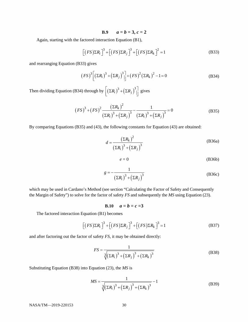
B.9 a = b = 3, c = 2 Again, starting with the factored interaction Equation (B1),
( ) ( ) ( )33 2 1i j kFS R FS R FS R Σ + Σ + Σ = (B33)
and rearranging Equation (B33) gives
( ) ( ) ( ) ( ) ( )33 3 2 2 1 0i j kFS R R FS R Σ + Σ + Σ − = (B34)
Then dividing Equation (B34) through by ( ) ( )33i jR R Σ + Σ
gives
( ) ( ) ( )( ) ( ) ( ) ( )
23 2
3 33 31 0k
i j i j
RFS FS
R R R R
Σ+ − =
Σ + Σ Σ + Σ (B35)
By comparing Equations (B35) and (43), the following constants for Equation (43) are obtained:
( )
( ) ( )
2
33k
i j
Rd
R R
Σ=
Σ + Σ (B36a)
e = 0 (B36b)
( ) ( )33
1
i j
gR R
= −Σ + Σ
(B36c)
which may be used in Cardano’s Method (see section “Calculating the Factor of Safety and Consequently the Margin of Safety”) to solve for the factor of safety FS and subsequently the MS using Equation (23).
B.10 a = b = c =3 The factored interaction Equation (B1) becomes
( ) ( ) ( )33 3 1i j kFS R FS R FS R Σ + Σ + Σ = (B37)
and after factoring out the factor of safety FS, it may be obtained directly:
( ) ( ) ( )33 33
1
i j k
FSR R R
=Σ + Σ + Σ
(B38)
Substituting Equation (B38) into Equation (23), the MS is
( ) ( ) ( )33 33
1 1i j k
MSR R R
= −Σ + Σ + Σ
(B39)
NASA/TM—2019-220153 31
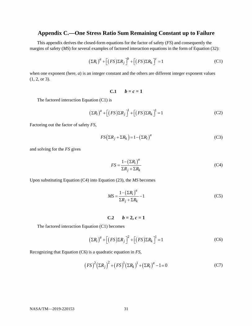
Appendix C.—One Stress Ratio Sum Remaining Constant up to Failure This appendix derives the closed-form equations for the factor of safety (FS) and consequently the
margins of safety (MS) for several examples of factored interaction equations in the form of Equation (32):
( ) ( ) ( ) 1b ca
i j kR FS R FS R Σ + Σ + Σ = (C1)
when one exponent (here, a) is an integer constant and the others are different integer exponent values (1, 2, or 3).
C.1 b = c = 1
The factored interaction Equation (C1) is
( ) ( ) ( )1 1 1ai j kR FS R FS R Σ + Σ + Σ = (C2)
Factoring out the factor of safety FS,
( ) ( )1 aj k iFS R R RΣ + Σ = − Σ (C3)
and solving for the FS gives
( )1 a
i
j k
RFS
R R− Σ
=Σ + Σ
(C4)
Upon substituting Equation (C4) into Equation (23), the MS becomes
( )1
1a
i
j k
RMS
R R− Σ
= −Σ + Σ
(C5)
C.2 b = 2, c = 1
The factored interaction Equation (C1) becomes
( ) ( ) ( )2 1 1ai j kR FS R FS R Σ + Σ + Σ = (C6)
Recognizing that Equation (C6) is a quadratic equation in FS,
( ) ( ) ( ) ( ) ( )22 1 1 1 0aj k iFS R FS R RΣ + Σ + Σ − = (C7)

NASA/TM—2019-220153 32
and solving for FS results in
( ) ( ) ( )
( )
22
2
4 1
2
ak k j i
j
R R R RFS
R
−Σ + Σ + Σ − Σ =Σ
(C8)
where the negative square root in the numerator has been omitted because the FS must be positive. Substituting Equation (C8) into Equation (23), the MS becomes
( ) ( ) ( )
( )
22
2
4 11
2
ak k j i
j
R R R RMS
R
−Σ + Σ + Σ − Σ = −Σ
(C9)
C.3 b = 3, c = 1
The factored interaction Equation (C1) becomes
( ) ( ) ( )3 1 1ai j kR FS R FS R Σ + Σ + Σ = (C10)
transforming Equation (C10) into the form of Equation (43), repeated here for convenience,
( ) ( ) ( )3 2 0FS d FS e FS g+ + + = (43)
it follows that
( ) ( ) ( )( ) ( )33 1 0aj k iFS R FS R RΣ + Σ + Σ − = (C11)
Dividing Equation (C11) by ( )3jRΣ gives
( ) ( ) ( )( )
( )( )
33 3
10
ak i
j j
R RFS FS
R R
Σ Σ −+ + =
Σ Σ (C12)
By comparing Equations (C12) and (43), the following constants for Equation (43) are obtained:
d = 0 (C13a)
( )( )3
k
j
Re
R
Σ=
Σ (C13b)
( )( )3
1ai
j
Rg
R
Σ −=
Σ (C13c)
NASA/TM—2019-220153 33
which may be used in Cardano’s Method (see section “Calculating the Factor of Safety and Consequently the Margin of Safety”) to solve for FS and consequently, the MS using Equation (23).
C.4 b = c = 2
The factored interaction Equation (C1) becomes
( ) ( ) ( )2 2 1ai j kR FS R FS R Σ + Σ + Σ = (C14)
Rearranging and factoring out the FS gives
( ) ( ) ( ) ( )22 2 1 aj k iFS R R R Σ + Σ = − Σ
(C15)
and solving for the FS results in
( )
( ) ( )2 2
1 ai
j k
RFS
R R
− Σ=
Σ + Σ (C16)
Substituting Equation (C16) into Equation (23), the MS is
( )
( ) ( )2 2
11
ai
j k
RMS
R R
− Σ= −
Σ + Σ (C17)
C.5 b = 3, c = 2
The factored interaction Equation (C1) becomes
( ) ( ) ( )3 2 1ai j kR FS R FS R Σ + Σ + Σ = (C18)
Transforming Equation (C18) into the form of Equation (43), as follows,
( ) ( ) ( ) ( ) ( )33 2 2 1 0aj k iFS R FS R RΣ + Σ + Σ − = (C19)
Dividing Equation (C19) by ( )3jRΣ gives
( ) ( ) ( )( )
( )( )
23 2
3 31
0a
k i
j j
R RFS FS
R R
Σ Σ −+ + =
Σ Σ (C20)
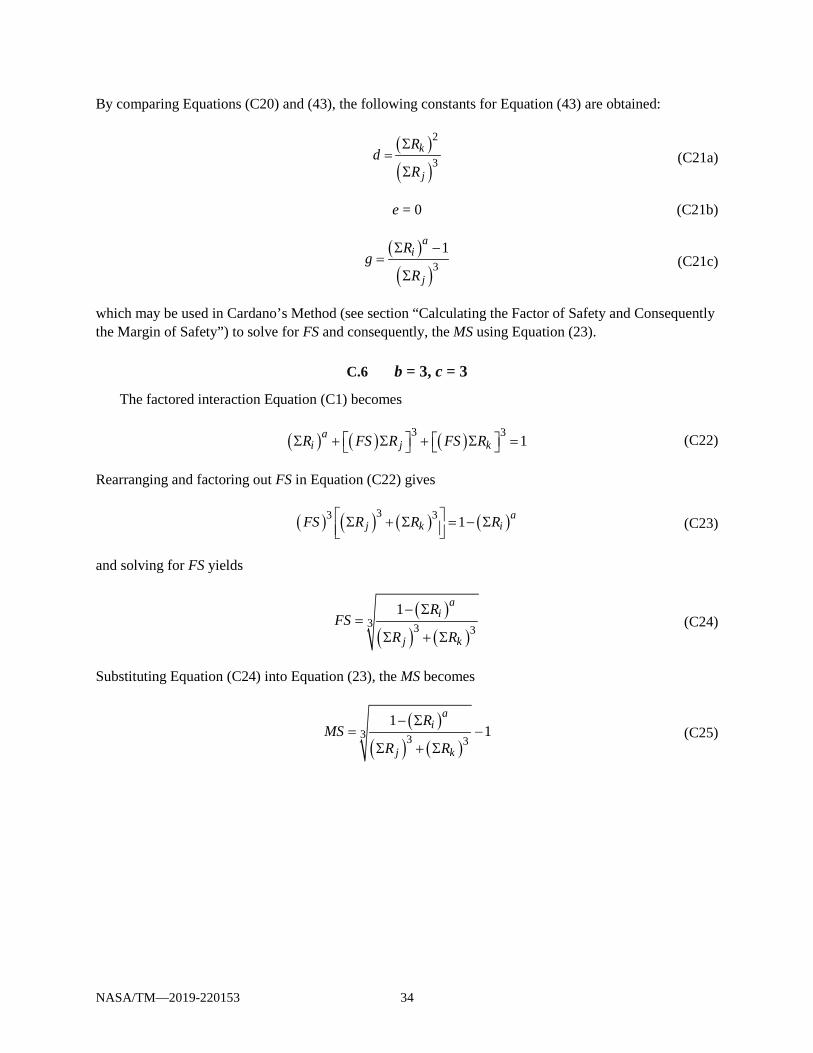
NASA/TM—2019-220153 34
By comparing Equations (C20) and (43), the following constants for Equation (43) are obtained:
( )( )
2
3k
j
Rd
R
Σ=
Σ (C21a)
e = 0 (C21b)
( )( )3
1ai
j
Rg
R
Σ −=
Σ (C21c)
which may be used in Cardano’s Method (see section “Calculating the Factor of Safety and Consequently the Margin of Safety”) to solve for FS and consequently, the MS using Equation (23).
C.6 b = 3, c = 3
The factored interaction Equation (C1) becomes
( ) ( ) ( )3 3 1ai j kR FS R FS R Σ + Σ + Σ = (C22)
Rearranging and factoring out FS in Equation (C22) gives
( ) ( ) ( ) ( )33 3 1 aj k iFS R R R Σ + Σ = − Σ
(C23)
and solving for FS yields
( )
( ) ( )3 3 3
1 ai
j k
RFS
R R
− Σ=
Σ + Σ (C24)
Substituting Equation (C24) into Equation (23), the MS becomes
( )
( ) ( )3 3 3
11
ai
j k
RMS
R R
− Σ= −
Σ + Σ (C25)
NASA/TM—2019-220153 35
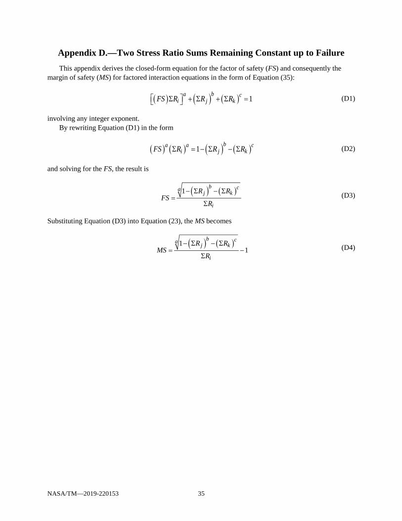
Appendix D.—Two Stress Ratio Sums Remaining Constant up to Failure This appendix derives the closed-form equation for the factor of safety (FS) and consequently the
margin of safety (MS) for factored interaction equations in the form of Equation (35):
( ) ( ) ( ) 1ba c
i j kFS R R R Σ + Σ + Σ = (D1)
involving any integer exponent. By rewriting Equation (D1) in the form
( ) ( ) ( ) ( )1ba a c
i j kFS R R RΣ = − Σ − Σ (D2)
and solving for the FS, the result is
( ) ( )1
b caj k
i
R RFS
R
− Σ − Σ=
Σ (D3)
Substituting Equation (D3) into Equation (23), the MS becomes
( ) ( )1
1b ca
j k
i
R RMS
R
− Σ − Σ= −
Σ (D4)
NASA/TM—2019-220153 36
References 1. Steeve, B.E.; and Wingate, R.J.: Aerospace Threaded Fastener Strength in Combined Shear and
Tension Loading. NASA/TM—2012-217454, 2012. http://ntrs.nasa.gov 2. Sarafin, Thomas P.; and Larson, Wiley: Spacecraft Structures and Mechanisms—From Concept to
Launch. Springer, Netherlands, 1995, p. 244. 3. Astronautic Structures Manual. Vol. 1, Sect. A3, NASA TM X–73305, 1975. 4. Peery, David J.: Aircraft Structures. McGraw-Hill Book Co., New York, NY, 1950. 5. Bruhn, E.F.: Analysis and Design of Flight Vehicle Structures. S.R. Jacobs & Associates, Inc., Tri-
State Offset Company, 1973, pp. C1.6–C1.7. 6. Barrett, Richard T.: Fastener Design Manual. NASA RP–1228, 1990, p. 21. http://ntrs.nasa.gov 7. Shanley, F.R.; and Ryder, E.I.: Stress Ratios: The Answer to the Combined Loading Problem.
Aviation, 1937. 8. Blodgett, Omer W.: Design of Welded Structures. James F. Lincoln Arc Welding Foundation,
Cleveland, OH, 1966. 9. McCombs, William F.: A Supplement to Analysis & Design of Flight Vehicle Structures, Bruhn, For
Increased Scope and Usefulness. Datatec, Dallas, TX, 1998. 10. Korn, Granino A.; and Korn, Theresa M.: Mathematical Handbook for Scientists and Engineers:
Definitions, Theorems, and Formulas for Reference and Review. McGraw-Hill, New York, NY, 1961, p. 23.
11. Requirements for Threaded Fastening Systems in Spaceflight Hardware. NASA–STD–5020A, 2018. 12. Press, William H., et al.: Numerical Recipes: The Art of Scientific Computing. University Press,
Cambridge, MA, 1990, p. 258.

