cal controls-cal 9400 autotune temperature controllers operating manual
DESCRIPTION
Cal Controls-CAL 9400 Dual Display Autotune Temperature Controller Operating Manual.TRANSCRIPT

Operating Manual
CAL ControlsTemperature Controllers
CAL ControlsTemperature Controllers
CAL Controls LtdBury Mead Road, Hitchin, Herts, SG5 1RT. UK
Tel: + 44 (0)1462-436161 Fax: + 44 (0)1462-451801email: [email protected]
http://www.cal-controls.com
CAL Controls Inc1580 S.Milwaukee Avenue, Libertyville, IL 60048. USA
Tel: (847) 680-7080 Fax: (847) 816-6852
000M06/33014/1/0798
CAL 9400 Dual DisplayAutotune Temperature
Controller
Sa
fe
ty
a
nd
W
ar
ra
nt
y
SAFETY AND WARRANTY INFORMATION
INSTALLATION
Designed for use:UL873 - only in products where the acceptability is determined byUnderwriters Laboratories Inc.EN61010-1 / CSA 22.2 No 1010.1 - 92To offer a minimum of Basic Insulation only.Suitable for installation within Catagory II and III and PollutionDegree 2.
SEE ELECTRICAL INSTALLATION P29 & P30
It is the responsibility of the installation engineer to ensure thisequipment is installed as specified in this manual and is incompliance with appropriate wiring regulations.
CONFIGURATION
All functions are front selectable, it is the responsibility of theinstalling engineer to ensure that the configuration is safe. Use theprogram lock to protect critical functions from tampering.
ULTIMATE SAFETY ALARMS
Do not use SP2 as the sole alarm where personal injury or damagemay be caused by equipment failure.
WARRANTY
CAL Controls warrant this product free from defect in workmanshipand materials for three (3) years from date of purchase.1 Should the unit malfunction, return it to the factory. If
defective it will be repaired or replaced at no charge.2 There are no user-servisable parts in this unit. This
waranty is void if the unit shows evidence of being tampered with or subjected to excessive heat, moisture,corrosion or other misuse.
3 Components which wear, or damage with misuse, are excluded e.g. relays.
4 CAL Controls shall not be responsible for any damage or losses however caused, which may be experienced as a result of the installation or use of this product. CAL Controls liability for any breach of this agreement shall not exceed the purchase price paid E. & O.E.
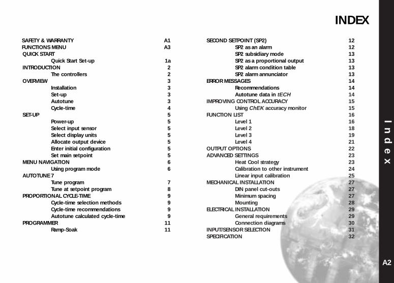
INDEX
SAFETY & WARRANTY A1FUNCTIONS MENU A3QUICK START
Quick Start Set-up 1aINTRODUCTION 2
The controllers 2OVERVIEW 3
Installation 3Set-up 3Autotune 3Cycle-time 4
SET-UP 5Power-up 5Select input sensor 5Select display units 5Allocate output device 5Enter initial configuration 5Set main setpoint 5
MENU NAVIGATION 6Using program mode 6
AUTOTUNE 7Tune program 7Tune at setpoint program 8
PROPORTIONAL CYCLE-TIME 9Cycle-time selection methods 9Cycle-time recommendations 9Autotune calculated cycle-time 9
PROGRAMMER 11Ramp-Soak 11
SECOND SETPOINT (SP2) 12SP2 as an alarm 12SP2 subsidiary mode 13SP2 as a proportional output 13SP2 alarm condition table 13SP2 alarm annunciator 13
ERROR MESSAGES 14Recommendations 14Autotune data in tECH 14
IMPROVING CONTROL ACCURACY 15Using ChEK accuracy monitor 15
FUNCTION LIST 16Level 1 16Level 2 18Level 3 19Level 4 21
OUTPUT OPTIONS 22ADVANCED SETTINGS 23
Heat Cool strategy 23Calibration to other instrument 24Linear input calibration 25
MECHANICAL INSTALLATION 27DIN panel cut-outs 27Minimum spacing 27Mounting 28
ELECTRICAL INSTALLATION 29General requirements 29Connection diagrams 30
INPUT/SENSOR SELECTION 31SPECIFICATION 32
In
de
x
A2A1

Sa
fe
ty
a
nd
W
ar
ra
nt
ySAFETY AND WARRANTY INFORMATION
INSTALLATION
Designed for use:UL873 - only in products where the acceptability is determined byUnderwriters Laboratories Inc.EN61010-1 / CSA 22.2 No 1010.1 - 92To offer a minimum of Basic Insulation only.Suitable for installation within Catagory II and III and PollutionDegree 2.
SEE ELECTRICAL INSTALLATION P29 & P30
It is the responsibility of the installation engineer to ensure thisequipment is installed as specified in this manual and is incompliance with appropriate wiring regulations.
CONFIGURATION
All functions are front selectable, it is the responsibility of theinstalling engineer to ensure that the configuration is safe. Use theprogram lock to protect critical functions from tampering.
ULTIMATE SAFETY ALARMS
Do not use SP2 as the sole alarm where personal injury or damagemay be caused by equipment failure.
WARRANTY
CAL Controls warrant this product free from defect in workmanshipand materials for three (3) years from date of purchase.1 Should the unit malfunction, return it to the factory. If
defective it will be repaired or replaced at no charge.2 There are no user-servisable parts in this unit. This
waranty is void if the unit shows evidence of being tampered with or subjected to excessive heat, moisture,corrosion or other misuse.
3 Components which wear, or damage with misuse, are excluded e.g. relays.
4 CAL Controls shall not be responsible for any damage or losses however caused, which may be experienced as a result of the installation or use of this product. CAL Controls liability for any breach of this agreement shall not exceed the purchase price paid E. & O.E.
INDEX
SAFETY & WARRANTY A1FUNCTIONS MENU A3QUICK START
Quick Start Set-up 1aINTRODUCTION 2
The controllers 2OVERVIEW 3
Installation 3Set-up 3Autotune 3Cycle-time 4
SET-UP 5Power-up 5Select input sensor 5Select display units 5Allocate output device 5Enter initial configuration 5Set main setpoint 5
MENU NAVIGATION 6Using program mode 6
AUTOTUNE 7Tune program 7Tune at setpoint program 8
PROPORTIONAL CYCLE-TIME 9Cycle-time selection methods 9Cycle-time recommendations 9Autotune calculated cycle-time 9
PROGRAMMER 11Ramp-Soak 11
SECOND SETPOINT (SP2) 12SP2 as an alarm 12SP2 subsidiary mode 13SP2 as a proportional output 13SP2 alarm condition table 13SP2 alarm annunciator 13
ERROR MESSAGES 14Recommendations 14Autotune data in tECH 14
IMPROVING CONTROL ACCURACY 15Using ChEK accuracy monitor 15
FUNCTION LIST 16Level 1 16Level 2 18Level 3 19Level 4 21
OUTPUT OPTIONS 22ADVANCED SETTINGS 23
Heat Cool strategy 23Calibration to other instrument 24Linear input calibration 25
MECHANICAL INSTALLATION 27DIN panel cut-outs 27Minimum spacing 27Mounting 28
ELECTRICAL INSTALLATION 29General requirements 29Connection diagrams 30
INPUT/SENSOR SELECTION 31SPECIFICATION 32
In
de
x
A2A1
FUNCTIONS MENUF
un
ct
io
ns
M
en
u
INSTRUMENT ADJUSTMENTS
To enter or exit program mode: Press together for 3 seconds
To scroll through functions: Press or
To change levels or options: Press together or together
To view setpoint: Press
To increase setpoint: Press together
To decrease setpoint: Press together
To reset an alarm or fault condition: Press together briefly
Notes: If in difficulty by becoming “lost” in program mode, press and together for 3 seconds to return to display mode, check the INSTRUMENT ADJUSTMENTS above and try again.
When in program mode, after 60 seconds of key inactivity the display will revert to eitheror, if the initial configuration has been completed, the measured value. Any settings already completed will be retained.
Setpoint 1Outputindicator(green)
Process temperature (PV) or Function (green)
Setpoint temperature (SP) or Option (orange)
Setpoint 2 Output indicator (red)
BAND INT.T DER.T DAC CYC.T OFST SP.LK SPRR SPRN SOAK SET.2 BND.2 CYC.2LEVL 1 TUNE
Autotune or Park
oFF; on; tu
nE; ParK; At.Sp
SP1 Prop band (gain)/h
yst
0.1 deg to 25% se
nsor f/s
(10°C/18°F)
Integral time (re
set)
Off; 0.1 to
60 min (5 min)
Derivative
time (ra
te)
Off; 1 to
200 sec (2
5 sec)
Derivative
approach
0.5 to 5.0 x b
And (1.5)
Cycle time or o
n/off
On.off; 0.1 to
81 sec
(20 sec)
Offset (m
anual reset)
0 to 50% x bAnd
(In.t =
off)
Setpoint lock (S
P1)
Off; on
Setpoint Ramp rate
0 to 9990 deg/hour
Ramp off/on
On; off;
hold
Soak time
Off; 0 to
1440 min
Adjust SP2 se
tpoint
+/– sensor fu
ll scale or
full scale
SP2 prop band/Gain/Hyst
0.1 deg to 100% se
nsor
f/s(2°C/3.6°F)
SP2 Cycle on/off
On.off; 0.1 to
81 sec
S P 1 S E T T I N G S
BAUD DATA DBUGLEVL C ADDR
Instrument address
0 to 255
Baud rate
1200: 2400: 4800:
9600: 19k2
Data format
18n1:18E1:18O1
Tx/Rx a
ctivity
Off; on
C O M M S S E T T I N G S
P R O G R A M M E R S E T T I N G S S P 2 S E T T I N G S
HAND PL.1 PL.2 SP2.A SP2.B DISP HI.SC LO.SC INPT UNITLEVL 2 SP1.P
Read SP1 output %
0 to 100% read only
SP1 manual output %
0 to 100% proportio
nal
mode only
Limit S
P1 output %
100 to 0%
Limit S
P2 output %
100 to 0%
Main SP2 mode
nonE; dV.h
i; dV.Lo
; bAnd;
FS.hi; FS,Lo
; Cool
Second SP2 mode
nonE; LtCH; hold; Lt
.ho;
nLin Display re
solution
1 or 0.1 degree
Set scale maxim
um
0.0 Sensor max to
sensor full sc
ale
Set scale minimum
0.0 Sensor min to
sensor
full scale
Select input se
nsor
nonESelect d
isplay u
nits
nonE; °C; °F
; bAr;
PSi; Ph; rh
; SEt
M A N U A L A D J U S T M E N T S S P 2 M O D E S R A N G I N G C O N F I G U R E I N P U T
SP2.D BURN REU.D REU.L SPAN ZERO CHEK READ TECH UER RSETLEVL 3 SP1.D
SP1 output devic
e
nonE; rlY; SSd *
SP2 output devic
e
nonE; SSd; rlY(re
ad only) *
Sensor burn-out
uP.SC; d
n.SC; 1u.2d; 1d.2u
Reverse outputs
1r.2d; 1d.2d; 1r.2r; 1d.2r
Reverse O/P LE
Ds
1n.2n; 1i.2n; 1n.2i; 1i.2i
Span adjustment
0.0 to 25% sensor f/
s
Zero Adjustment
0.0 to 25%
sensor full sc
ale
Set Monito
r
Off; on
Read Monitor
VAr; hi; lo
deg
Read Tune Data
CtA; Ctb; Ct1; Ct2; Ct3;
Ct4; oS1; uS; o
S2
Software ve
rsion
Consult unit
RESETnonE; A
LL
C O N F I G U R E O U T P U T S A F E T Y S E T T I N G S C A L I B R AT I O N P E R F O R M A N C E D ATA
PROG NO.AL DIS.S DER.SLEVL 4 LOCK
Security lock
nonE; LEV 3; LE
V 2; ALL
Disable program auto-exit
Auto; StAY
Disable -AL- a
larm display
Off; on
Display a
veraging
dir; 1 to
32 (6)
Derivative
sensiti
vity
0.1 to 1.0 x d
Er.t (0.5)
U S E R - P R O T E C T E D S E T T I N G S
PROGRAM ENTRY
Level C only visablewhen COMMSOption fitted
QUICK START ENTRY
KEY TO VIEW FUNCTIONS
KEY
OR
TO
GET
HER
TO
CH
AN
GE
LEVE
LS O
R O
PTIO
NS
Range of Adjustment shown in red underdescription. If applicable, factory settings shownin bold.* Note: Dual Relay and Dual SSd Output OptionsModels 9411 and 9422 have their outputs pre-configured. (see page 22)
A3
INPTNONE
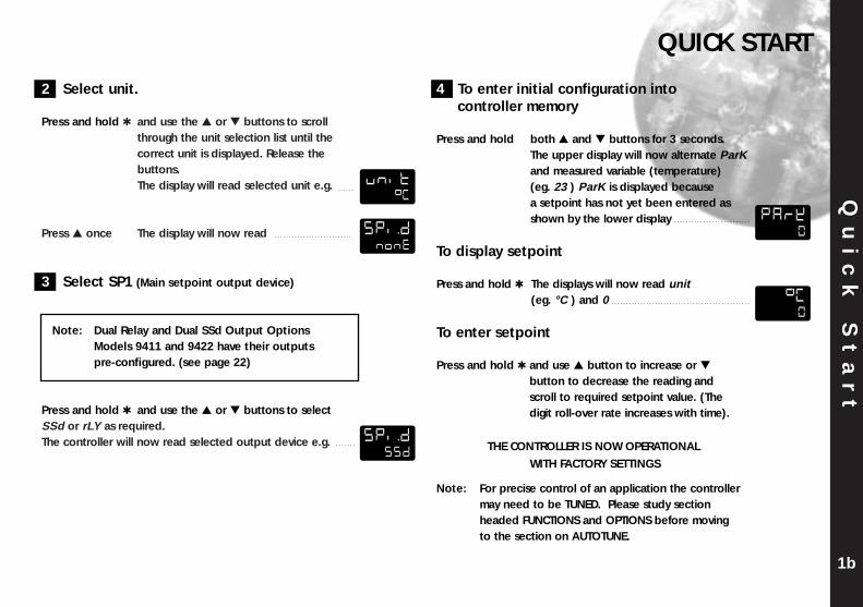
2 Select unit.
Press and hold and use the or buttons to scroll through the unit selection list until the correct unit is displayed. Release the buttons.The display will read selected unit e.g.
Press once The display will now read
3 Select SP1 (Main setpoint output device)
Note: Dual Relay and Dual SSd Output Options Models 9411 and 9422 have their outputs pre-configured. (see page 22)
Press and hold and use the or buttons to select SSd or rLY as required. The controller will now read selected output device e.g.
Qu
ic
k
St
ar
tQUICK START
1b
4 To enter initial configuration into controller memory
Press and hold both and buttons for 3 seconds. The upper display will now alternate ParKand measured variable (temperature) (eg. 23 ) ParK is displayed because a setpoint has not yet been entered as shown by the lower display
To display setpoint
Press and hold The displays will now read unit (eg. °C ) and 0
To enter setpoint
Press and hold and use button to increase or
button to decrease the reading and scroll to required setpoint value. (The digit roll-over rate increases with time).
THE CONTROLLER IS NOW OPERATIONAL
WITH FACTORY SETTINGS
Note: For precise control of an application the controller may need to be TUNED. Please study section headed FUNCTIONS and OPTIONS before moving to the section on AUTOTUNE.
UNIT*C
SPI.DNONE
SPI.DSSD
PARK0
*C0
In
tr
od
uc
ti
on
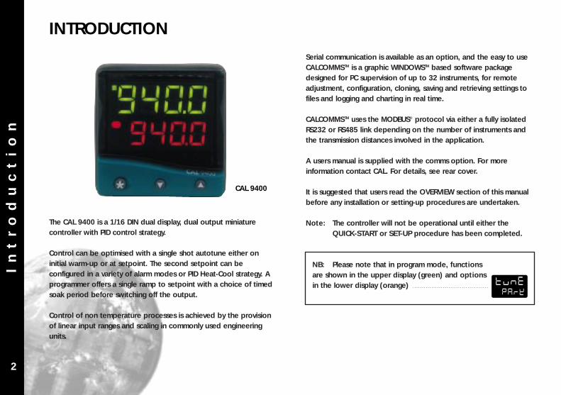
INTRODUCTION
The CAL 9400 is a 1/16 DIN dual display, dual output miniaturecontroller with PID control strategy.
Control can be optimised with a single shot autotune either oninitial warm-up or at setpoint. The second setpoint can beconfigured in a variety of alarm modes or PID Heat-Cool strategy. Aprogrammer offers a single ramp to setpoint with a choice of timedsoak period before switching off the output.
Control of non temperature processes is achieved by the provisionof linear input ranges and scaling in commonly used engineeringunits.
Serial communication is available as an option, and the easy to useCALCOMMSTM is a graphic WINDOWSTM based software packagedesigned for PC supervision of up to 32 instruments, for remoteadjustment, configuration, cloning, saving and retrieving settings tofiles and logging and charting in real time.
CALCOMMSTM uses the MODBUS® protocol via either a fully isolatedRS232 or RS485 link depending on the number of instruments andthe transmission distances involved in the application.
A users manual is supplied with the comms option. For moreinformation contact CAL. For details, see rear cover.
It is suggested that users read the OVERVIEW section of this manualbefore any installation or setting-up procedures are undertaken.
Note: The controller will not be operational until either the QUICK-START or SET-UP procedure has been completed.
NB: Please note that in program mode, functionsare shown in the upper display (green) and optionsin the lower display (orange)
2
CAL 9400
TUNEPARK
Ov
er
vi
ew
OVERVIEW
INSTALLATION
The Model 9400 controller is designed to be mounted in a 1/16 DINpanel cut-out. See the INSTALLATION section.
SET-UP
After installation the controller requires programming with thefollowing information:
Type of Input SensorOperating unit (C or F etc)Type of Output DeviceTemperature Setpoint
Note: The controller will not be operational until thisinformation is entered.
When the above information has been programmed into thecontroller it will be operational with the following factory PID(proportional band, integral time, derivative time) settings.
Proportional band/Gain 10°C/18°FIntegral time/Reset 5 minsProportional cycle-time 20 secsDerivative time/Rate 25 secsDAC Derivative approach control 1.5
AUTOTUNE
To precisely control an application the controller will need to be‘tuned’ using the built-in ‘AUTOTUNE’ feature. Autotune ‘teaches’the controller the main characteristics of the process and ‘learns’ bycycling the output on and off. The results are measured and used tocalculate optimum PID values which are automatically entered in thecontroller memory.
During AUTOTUNE the optimum cycle-time is calculated but is notautomatically implemented. The cycle-time requires manualacceptance unless pre-selected.
To ensure good control over a wide range of applications twoversions of the Autotune program are provided, TUNE and TUNE ATSETPOINT.
The TUNE method normally achieves the best results. Starting withthe load cool, tuning occurs during warm-up preventing overshoot.This method of tuning is recommended.
The TUNE AT SETPOINT method is used for specialist applications.eg. Heat-cool, multizones and processes below 100°C/200°F. Duringthe tuning cycle some overshoot occurs because the tuning cycle isat set point.The DAC setting is not re-calculated.
3
Ov
er
vi
ew
CYCLE-TIME
The choice of cycle-time is influenced by the external switchingdevice or load. e.g. contactor, SSR, Valve. A setting that is too longfor the process will cause oscillation and a setting that is too shortwill cause unnecessary wear to an electro-mechanical switchingdevice.
Cycle-time selection methodsThe following methods of cycle-time selection may be used:
Autotune calculated After Autotune has been run and completed the calculated cycle-time can be manually accepted or adjusted to suit the switchingdevice. For selection method see Select Autotune CalculatedCycle-time.
Pre-select autotune cycle-timeThe controller can be programmed to automatically accept thecalculated Autotune cycle-time. For selection method see Pre-Select Automatic Acceptance of Any Autotune Cycle-time.
Pre-select before autotuneThe controller can be programmed manually with any cycle-timebetween 0.1 and 81 sec. This cycle-time will not be changed by anyAutotune functions. For selection method see Pre-Select Cycle-time Before Autotune.
Factory setTo use the 20 sec factory set cycle-time no action is neededwhether Autotune is used or not.
Further information can be programmed into the controller, see
SECOND SETPOINT, RANGING AND SETPOINT LOCK, IMPROVING
CONTROL ACCURACY
Functions and optionsThe facilities of the controller are selected from the multi-level menuusing the front panel mounted buttons.
Note: It is advisable to study this section before anyprogramming is undertaken.
Each level within the multi-level menu offers different functions, seeFUNCTIONS MENU for menu of main functions. Each function has arange of user selections or options, see FUNCTION LIST forfunctions and options details.
The controller has two modes, program mode and operating mode.When in program mode the controller can be programmed withsettings and functions to suit the application. When in operatingmode the controller uses the setting and functions entered in theprogram mode to control the application and also displays both theprocess variable and setpoint temperatures. For full details on howto program the controller see VIEWING AND SELECTINGFUNCTIONS.
Note: In this manual the letter k is represented by thecharacter K
4
Se
t-
up
SET-UP
5
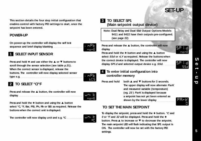
This section details the four step initial configuration thatenables control with factory PID settings to start, once thesetpoint has been entered.
POWER-UP
On power-up the controller will display the self testsequence and brief display blanking
1 SELECT INPUT SENSOR
Press and hold and use either the or buttons toscroll through the sensor selection (see table p.31). When the correct sensor is displayed, release the buttons. The controller will now display selected sensortype e.g.
2 TO SELECT °C/°F
Press and release the button, the controller will nowdisplay
Press and hold the button and using the buttonselect °C, °F, Bar, PSI, Ph, Rh or SEt as required. Release thebuttons when the correct unit is displayed.
The controller will now display unit and e.g. ºC
3 TO SELECT SP1(Main setpoint output device)
Note: Dual Relay and Dual SSd Output Options Models 9411 and 9422 have their outputs pre-configured. (see page 22)
Press and release the button, the controller will nowdisplayPress and hold the button and using the buttonselect SSd or rLY as required. Release the buttons whenthe correct device is displayed. The controller will nowdisplay SPI.d and selected output device e.g. SSd.
4 To enter initial configuration into controller memory
Press and hold both and buttons for 3 seconds. The upper display will now alternate ParKand measured variable (temperature) (eg. 23 ) ParK is displayed because a setpoint has not yet been entered as shown by the lower display
TO SET THE MAIN SETPOINT
To display the setpoint, press and hold the button. °C and0 or °F and 32 will be displayed. Press and hold the button. Press to increase or to decrease the setpoint.The main setpoint LED will flash indicating that SP1 output isON. The controller will now be set with the factory PIDsettings.
INPTNONE
SP1>DNONE
SP1>DSSD
INPTTCS
UNITNONE
UNIT*C
PARK0

Me
nu
N
av
ig
at
io
nMENU NAVIGATION
To change an option value or settingPress and hold the button, then press to increase or todecrease the value or select the next option.
Note: Check the new option value before moving to another function or exiting program mode.
To change levelsPress and hold to scroll through the functions until LEUL isdisplayed. Release to display current level. Press and hold the button, then press to increase or to decrease the level.Release buttons when required level is obtained.
To exit program modePress and hold both and buttons for at least 3 seconds.
Note: Control commences with any new instructions now entered in the memory.
REMINDER OF INSTRUMENT ADJUSTMENTS
Press together for 3 seconds for program entry or exit.Press or to scroll through functions.Press together or together to change levels or alteroptions.Note: If in difficulty by becoming “lost” in program mode,
press and together for 3 seconds to returnto display mode, check the Menu Navigationsummary above and try again.
The facilities of the controller are selected from the multi-level menuusing the front panel mounted buttons. Each level within the multi-level menu offers different functions, seeFUNCTIONS MENU page A3. Each function has a range of userselections or options, see FUNCTION LIST pages 16–22
In operating mode, the upper (green) display reads processtemperature (PV) and the lower (orange) display reads setpointtemperature (SP).When in program mode, settings of each function, shown in theupper display, can be made by selecting an appropriate optionfrom the lower display.
USING PROGRAM MODE
Note: The controller will auto-exit program mode after 60 seconds of inactivity.
To enter program mode from normal operating modePress and hold both and buttons for at least 3 seconds.Release the buttons together and the controller willnow display the function and option (setting of thatfunction), e.g.
To view function on the same level and display current optionPress or button once to view the next function. Press and hold or buttons to scroll through functions. Thecurrent option or function value is shown in the lower display.
6
TUNEOFF
Au
to
tu
ne
AUTOTUNE
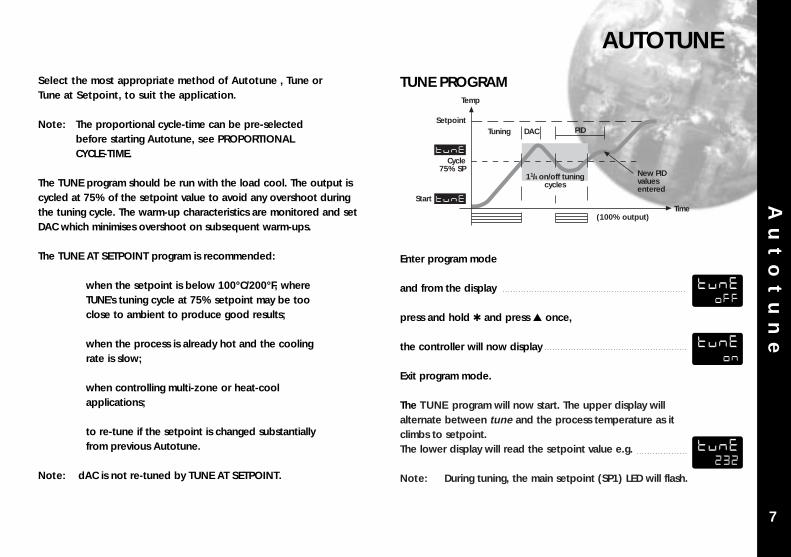
Select the most appropriate method of Autotune , Tune orTune at Setpoint, to suit the application.
Note: The proportional cycle-time can be pre-selected before starting Autotune, see PROPORTIONAL CYCLE-TIME.
The TUNE program should be run with the load cool. The output iscycled at 75% of the setpoint value to avoid any overshoot duringthe tuning cycle. The warm-up characteristics are monitored and setDAC which minimises overshoot on subsequent warm-ups.
The TUNE AT SETPOINT program is recommended:
when the setpoint is below 100°C/200°F, whereTUNE’s tuning cycle at 75% setpoint may be tooclose to ambient to produce good results;
when the process is already hot and the coolingrate is slow;
when controlling multi-zone or heat-coolapplications;
to re-tune if the setpoint is changed substantiallyfrom previous Autotune.
Note: dAC is not re-tuned by TUNE AT SETPOINT.
TUNE PROGRAM
Enter program mode
and from the display
press and hold and press once,
the controller will now display
Exit program mode.
The TUNE program will now start. The upper display willalternate between tune and the process temperature as itclimbs to setpoint.The lower display will read the setpoint value e.g.
Note: During tuning, the main setpoint (SP1) LED will flash.
Temp
Setpoint
Cycle75% SP
Start
TUNE
TUNE
Tuning DAC PID
11/4 on/off tuningcycles
New PIDvaluesentered
Time(100% output)
7
TUNEOFF
TUNEON
TUNE232
Au
to
tu
ne
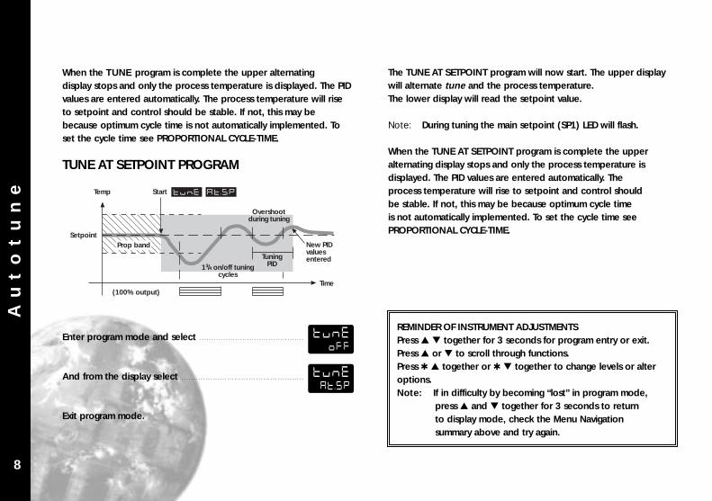
The TUNE AT SETPOINT program will now start. The upper displaywill alternate tune and the process temperature.The lower display will read the setpoint value.
Note: During tuning the main setpoint (SP1) LED will flash.
When the TUNE AT SETPOINT program is complete the upperalternating display stops and only the process temperature isdisplayed. The PID values are entered automatically. Theprocess temperature will rise to setpoint and control shouldbe stable. If not, this may be because optimum cycle timeis not automatically implemented. To set the cycle time seePROPORTIONAL CYCLE-TIME.
When the TUNE program is complete the upper alternatingdisplay stops and only the process temperature is displayed. The PIDvalues are entered automatically. The process temperature will riseto setpoint and control should be stable. If not, this may bebecause optimum cycle time is not automatically implemented. Toset the cycle time see PROPORTIONAL CYCLE-TIME.
TUNE AT SETPOINT PROGRAM
Enter program mode and select
And from the display select
Exit program mode.
Temp
Setpoint
Start TUNE
TuningPID13/4 on/off tuning
cycles
New PIDvaluesentered
Time(100% output)
AT.SP
Overshootduring tuning
Prop band
REMINDER OF INSTRUMENT ADJUSTMENTSPress together for 3 seconds for program entry or exit.Press or to scroll through functions.Press together or together to change levels or alteroptions.Note: If in difficulty by becoming “lost” in program mode,
press and together for 3 seconds to returnto display mode, check the Menu Navigationsummary above and try again.
8
TUNEOFF
TUNEAT.SP
Pr
op
or
ti
on
al
c
yc
le
-t
im
e
The choice of cycle-time is influenced by the external switchingdevice or load. eg. contactor, SSR, valve. A setting that is too longfor the process will cause oscillation and a setting that is too shortwill cause unnecessary wear to an electro-mechanical switchingdevice.
CYCLE-TIME SELECTION METHODS
The following methods of cycle-time selection may be used:
Autotune calculated After Autotune has been run and completed the calculatedcycle-time can be manually accepted or adjusted to suit theswitching device. For selection method see Select AutotuneCalculated Cycle-time.
Pre-select Autotune cycle-timeThe controller can be programmed to automatically acceptany calculated Autotune cycle-time. For selection methodsee Pre-Select Automatic Acceptance of Any AutotuneCycle-time, page 10.
Pre-select before AutotuneThe controller can be programmed manually with anycycle-time between 0.1 and 81 sec. This cycle-time will not bechanged by any Autotune functions. For selection method see Pre-Select Cycle-time Before Autotune, page 10.
Factory setTo use the 20 sec factory set cycle-time no action is neededwhether autotune is used or not.
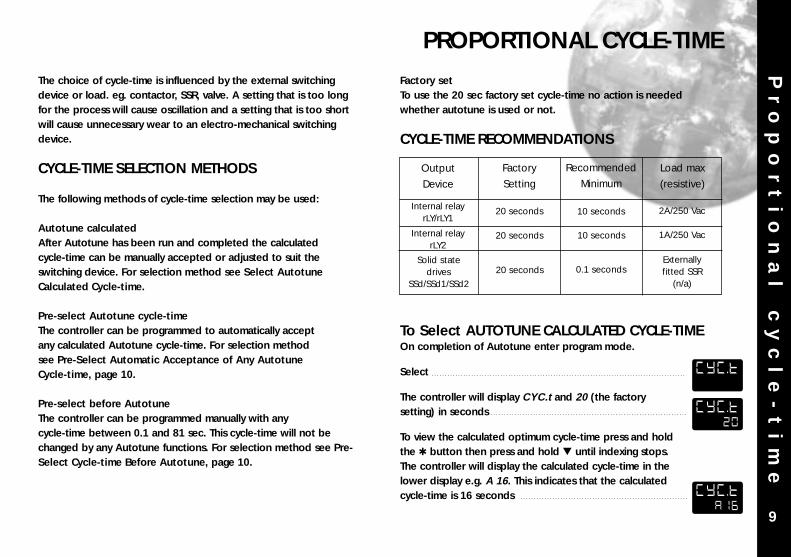
CYCLE-TIME RECOMMENDATIONS
To Select AUTOTUNE CALCULATED CYCLE-TIMEOn completion of Autotune enter program mode.
Select
The controller will display CYC.t and 20 (the factory setting) in seconds
To view the calculated optimum cycle-time press and holdthe button then press and hold until indexing stops.The controller will display the calculated cycle-time in the lower display e.g. A 16. This indicates that the calculated cycle-time is 16 seconds
PROPORTIONAL CYCLE-TIME
9
Output
Device
Load max
(resistive)
Factory
Setting
Recommended
Minimum
Internal relayrLY/rLY1
Internal relayrLY2
20 seconds
20 seconds
20 seconds
10 seconds 2A/250 Vac
1A/250 Vac
Externallyfitted SSR
(n/a)
Solid statedrives
SSd/SSd1/SSd2
10 seconds
0.1 seconds
CYC.T
CYC.T20
CYC.TA16
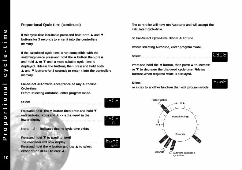
If this cycle-time is suitable press and hold both and buttons for 3 seconds to enter it into the controllersmemory.
If the calculated cycle-time is not compatible with theswitching device press and hold the button then pressand hold or until a more suitable cycle-time isdisplayed. Release the buttons, then press and hold both and buttons for 3 seconds to enter it into the controllersmemory.
Pre-Select Automatic Acceptance of Any AutotuneCycle-timeBefore selecting Autotune, enter program mode.
Select CYC.T
Press and hold the button then press and hold
until indexing stops and A - - is displayed in the lower display
Note: A - - indicates that no cycle-time exists.
Press and hold to scroll to tunEThe controller will now displayPress and hold the button and use to select either on or At.SP . Release .
The controller will now run Autotune and will accept thecalculated cycle-time.
To Pre-Select Cycle-time Before Autotune
Before selecting Autotune, enter program mode.
Select
Press and hold the button, then press to increaseor to decrease the displayed cycle-time. Releasebuttons when required value is displayed.
Selector index to another function then exit program mode.
Pr
op
or
ti
on
al
c
yc
le
-t
im
e
10
81
ON
.OF
0.1
20
A
--
Factory setting
ON/OFF Autotune calculatedcycle-time
Manual settings
Seconds
Proportional Cycle-time (continued)
CYC.T
CYC.TA--
TUNEOFF
CYC.T
TUNE
Pr
og
ra
mm
er
RAMP-SOAK
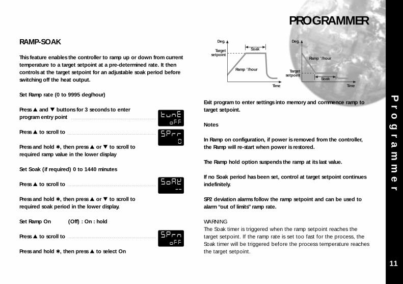
This feature enables the controller to ramp up or down from currenttemperature to a target setpoint at a pre-determined rate. It thencontrols at the target setpoint for an adjustable soak period beforeswitching off the heat output.
Set Ramp rate (0 to 9995 deg/hour)
Press and buttons for 3 seconds to enter program entry point
Press to scroll to
Press and hold , then press or to scroll to required ramp value in the lower display
Set Soak (if required) 0 to 1440 minutes
Press to scroll to
Press and hold , then press or to scroll to required soak period in the lower display.
Set Ramp On (Off) : On : hold
Press to scroll to
Press and hold , then press to select On
Exit program to enter settings into memory and commence ramp totarget setpoint.
Notes
In Ramp on configuration, if power is removed from the controller,the Ramp will re-start when power is restored.
The Ramp hold option suspends the ramp at its last value.
If no Soak period has been set, control at target setpoint continuesindefinitely.
SP2 deviation alarms follow the ramp setpoint and can be used toalarm “out of limits” ramp rate.
WARNINGThe Soak timer is triggered when the ramp setpoint reaches thetarget setpoint. If the ramp rate is set too fast for the process, theSoak timer will be triggered before the process temperature reachesthe target setpoint.
PROGRAMMER
Targetsetpoint
Deg.
Ramp °/hour
Time
Soak
Targetsetpoint
Deg.
Ramp °/hour
Time
Soak
11
TUNEOFF
SPRR0
SOAK--
SPRNOFF
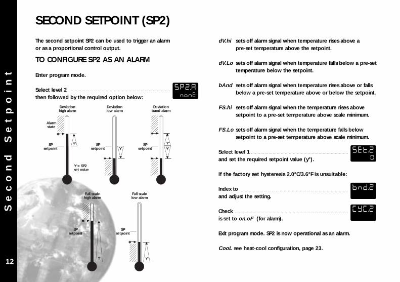
The second setpoint SP2 can be used to trigger an alarmor as a proportional control output.
TO CONFIGURE SP2 AS AN ALARM
Enter program mode.
Select level 2then followed by the required option below:
dV.hi sets off alarm signal when temperature rises above a pre-set temperature above the setpoint.
dV.Lo sets off alarm signal when temperature falls below a pre-set temperature below the setpoint.
bAnd sets off alarm signal when temperature rises above or falls below a pre-set temperature above or below the setpoint.
FS.hi sets off alarm signal when the temperature rises above setpoint to a pre-set temperature above scale minimum.
FS.Lo sets off alarm signal when the temperature falls below setpoint to a pre-set temperature above scale minimum.
Select level 1and set the required setpoint value (y°).
If the factory set hysteresis 2.0°C/3.6°F is unsuitable:
Index toand adjust the setting.
Checkis set to on.oF (for alarm).
Exit program mode. SP2 is now operational as an alarm.
CooL see heat-cool configuration, page 23.
Se
co
nd
S
et
po
in
tSECOND SETPOINT (SP2)
Y°
Deviationhigh alarm
Deviationlow alarm
Deviationband alarm
Alarmstate
SPsetpoint Y° Y°
Y°SPsetpoint
SPsetpoint
Y°= SP2set value
Y°
Full scalehigh alarm
Full scalelow alarm
SPsetpoint
SPsetpoint
Y°12
SP2.ANONE
SET.20
BND.2
CYC.2
Se
co
nd
S
et
po
in
t
SUBSIDIARY SP2 MODE:Latch/sequence or non-linear cool.
Latch alarm LtCh
When activated, the alarm latches until manually reset, eventhough the alarm condition may have disappeared.
Sequence alarm hoLd
When hoLd is selected, in any alarm mode, it prevents analarm signal on power-up. The alarm is enabled only afterthe process temperature has reached setpoint.
TO CONFIGURE SP2 AS A PROPORTIONALCONTROL OUTPUT
In level 2 selectthen select the required option.
In level 1 selectand then set the required proportional band.
In level 1 selectand then set the setpoint (SP2) value (y°).
SP2 OUTPUT AND LED INDICATION STATES - INALARM CONDITION
SP2 ALARM ANNUNCIATORWhen an SP2 alarm mode is selected in SP2.A the alarmannunciator -AL- is displayed, alternating with the processtemperature, during alarm condition.
Note: The annunciator may be disabled by selecting functionand option on in level 4.
SP2 in cool strategy(See heat-cool configuration in ADVANCED SETTINGS page 23).
Without sequencealarm
Alarms onpower up
SPsetpoint Y°
Y°SP
setpointSP
setpointSP
setpoint
No alarm onpower up
With sequence alarm
Alarmenabled
Alarm operatesnormally
Alarm type ON-OFFoperating mode
Proportionaloperating mode
FS.HI
COOL
FS.LO
BAND
DV.LO
DV.HI
Deviation
Full scale
Strategy
SP2Output state
SP2LED state
SP2Output state
SP2LED state
BAND : on-off mode only
Output ON(Relay or SSd energised)
Output OFF(Relay or SSd de-energised) LED ON
Temperature above setpoint
13
SP2.B
SP2.A
BND.2
SET.2
NO.ALON
Er
ro
r
Me
ss
ag
es
ERROR MESSAGES
Temp
Setpoint
Cycle75% SP
Start
TUNE
TUNE
Tuning
DAC PID
New PIDvaluesentered
Time(100% output)
oS 1 oS 2
Ct A
Ct b
Ct 3
Ct 4
uS
Ct 1
Ct 2
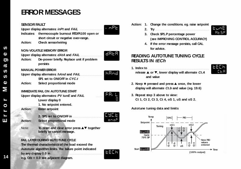
SENSOR FAULTUpper display alternates: inPt and FAiLIndicates: thermocouple burnout RTD/Pt100 open or
short circuit or negative over-range.Action: Check sensor/wiring
NON-VOLATILE MEMORY ERRORUpper display alternates: dAtA and FAiLAction: De-power briefly. Replace unit if problem
persists
MANUAL POWER ERRORUpper display alternates: hAnd and FAiL
SP1 set to ON/OFF in CYC.tAction: Select proportional mode
IMMEDIATE FAIL ON AUTOTUNE STARTUpper display alternates: PV tunE and FAiL
Lower display 01. No setpoint entered.
Action: Enter setpoint
2. SP1 set to ON/OFF inAction: Select proportional mode
Note: To reset and clear error press together briefly to cancel message.
FAIL LATER DURING AUTOTUNE CYCLEThe thermal characteristics of the load exceed the Autotune algorithm limits. The failure point indicated by any display 0.0 ine.g. Ctb = 0.0 see adjacent diagram.
Action: 1. Change the conditions. eg. raise setpoint
2. Try
3. Check SP1.P percentage power
(see IMPROVING CONTROL ACCURACY)
4. If the error message persists, call CAL
for advice.
READING AUTOTUNE TUNING CYCLE RESULTS IN tECh
1. Index torelease or , lower display will alternate Ct.A
and value
2. Keep pressed and press once, the lower display will alternate Ct.b and value (eg. 19.6)
3. Repeat step 3 above to view:Ct 1, Ct 2, Ct 3, Ct 4, oS 1, uS and oS 2.
Autotune tuning data and limits
14
INPT
DATA
HAND
FAIL0
CYC.TON.OF
TECH
TUNEAT.SP
TECHCT.A
Im
pr
ov
in
g
Co
nt
ro
l
Ac
cu
ra
cy
IMPROVING CONTROL ACCURACY
TempMaximum
Time
Variance
VAr°hi°
±0.1°
MinimumLo°
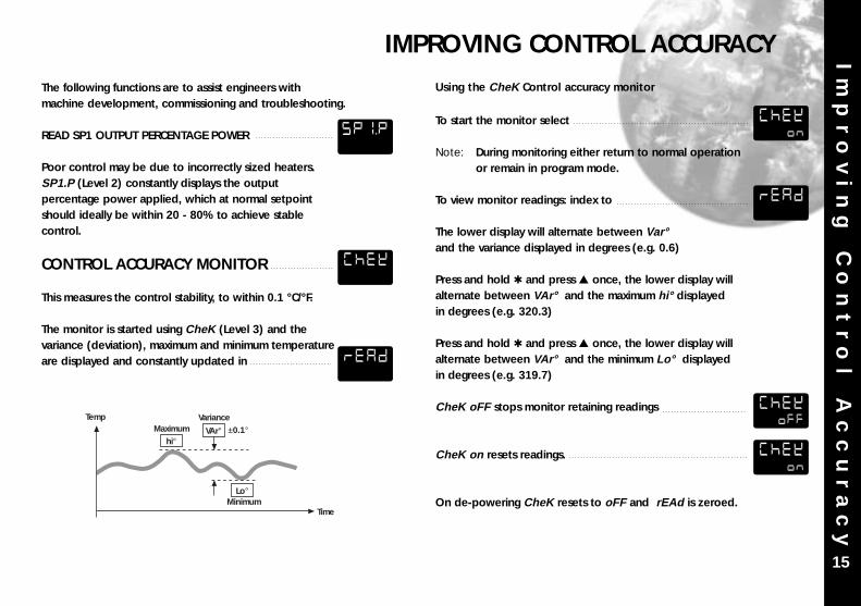
The following functions are to assist engineers withmachine development, commissioning and troubleshooting.
READ SP1 OUTPUT PERCENTAGE POWER
Poor control may be due to incorrectly sized heaters.SP1.P (Level 2) constantly displays the outputpercentage power applied, which at normal setpointshould ideally be within 20 - 80% to achieve stablecontrol.
CONTROL ACCURACY MONITOR
This measures the control stability, to within 0.1 °C/°F.
The monitor is started using CheK (Level 3) and thevariance (deviation), maximum and minimum temperatureare displayed and constantly updated in
Using the CheK Control accuracy monitor
To start the monitor select
Note: During monitoring either return to normal operation or remain in program mode.
To view monitor readings: index to
The lower display will alternate between Var°and the variance displayed in degrees (e.g. 0.6)
Press and hold and press once, the lower display willalternate between VAr° and the maximum hi° displayedin degrees (e.g. 320.3)
Press and hold and press once, the lower display willalternate between VAr° and the minimum Lo° displayedin degrees (e.g. 319.7)
CheK oFF stops monitor retaining readings
CheK on resets readings.
On de-powering CheK resets to oFF and rEAd is zeroed.
15
SP1.P
CHEK
CHEKON
READ
CHEKOFF
CHEKON
READ
Fu
nc
ti
on
L
is
tFUNCTION LIST (Levels 1 to 4)
BAND
Too narrow(oscillates)
increase
Too wide(slow warm up and response)
decrease BAND
Note: A Functions Menu is shown on the cover fold-out A3
LEVEL 1
Function Options [Factory settings] shown in brackets
SELECT AUTOTUNE
[oFF] on ParK At.SpUsed to switch the Autotune feature on and off, to select ParK or Autotune at setpoint.ParK temporarily turns the output(s) off. To use selectParK and exit program mode. To disable re-enter program at tunE and select oFF.
SP1 OPERATING PARAMETERS
0.1 to * °C/°F [10ºC/18ºF]SP1 proportional band/Gain or Hysteresis* 25% sensor maximumProportional control eliminates the cycling of on-off control. Heater power is reduced, by time proportioning action, across the proportional band.
Function Options [Factory settings] shown in brackets
oFF 0.1 to 60 minutes [5.0]SP1 integral time/resetAuto-corrects proportional control offset error
oFF 1 - 200 seconds [25]SP1 derivate time/rateSuppresses overshoot and speeds response to disturbances
0.5 - 5.0 x bAnd [1.5]SP1 derivative approach control dACTunes warm-up characteristics, independent of normal operating conditions, by controlling when derivative action starts during warm-up (smaller dAC value = nearer setpoint).
Too short(overshoots and oscillates)
Too long(slow warm up and response)
Too short(slow warm up and response,under corrects)
Too long(oscillates and over corrects)
* * disturbance
Too small(overshoots)
Too large(slow stepped warm up)
16
TUNE
BAND
INT.T
DER.T
DAC
Fu
nc
ti
on
L
is
t
Function Options [Factory settings] shown in brackets
A - - on.oF 0.1 - 81 sec [20]SP1 proportional cycle-time (see pages 9/10)Determines the cycle rate of the output device forproportional control. Select on.oF for ON/OFF mode.
[0] to * °C/°FSP1 offset/manual reset* ±50% bAnd . Applicable in proportional and ON/OFFmode with integral disable: Int.t oFF .
[oFF] onLock main setpointLocks the setpoint preventing unauthorised adjustment.
PROGRAMMER SETTINGS (see page 11)
[0] to 9995 deg/hourSets the ramp rate
on [oFF] hoLdSwitches the ramp on or off, or hold at last ramp value
[oFF] 0 to 1440 minSets the soak time
SP2 OPERATING PARAMETERS (see pages 12/13)
Function Options [Factory settings] shown in brackets
0 to * °C/°F [0]Adjust SP2 setpoint* Deviation Alarms DV.hi, DV.Lo, bAnd25% sensor maximum (see figure 7).* Full scale alarms FS.hi, FS.Losensor range f/s (see figure 8)
0.1 - * °C/°F [2.0 °C/3.6°F]Adjust SP2 hysteresis or proportional band/gain(see CyC.2 setting)* 25% sensor f/s
[on.oFF] 0.1–81 secondsSelect SP2 ON/OFF or proportional cycle-timeSelect on.oFF for ON/OFF mode, or the cycle rate ofSP2 output device for proportional mode.
17
LEVEL 1 (continued)
CYC.T
OFST
SP>LK
SPRR
SPRN
SOAK
SET.2
BND.2
CYC.2
Fu
nc
ti
on
L
is
t
LEVEL 2Function Options [Factory settings] shown in brackets
MANUAL CONTROL MODES
0 to 100 % ‘read only’Read SP1 output percentage power
[oFF] 1 to 100 % (not in ON/OFF)SP1 manual percentage power controlFor manual control should a sensor fail.Record typical SP1.P values beforehand.
100 to 0 % duty cycle [100]Set SP1 power limit percentageLimits maximum SP1 heating power during warm-upand in proportional band.
100 to 0 % duty cycle [100]Set SP2 percentage power limit (cooling)
SP2 OPERATING MODES (see page 12/13)
[nonE] dV.hi dV.Lo bAnd FS.hi FS.Lo CoolMain SP2 operating mode
Function Options [Factory settings] shown in brackets
[nonE] LtCh hoLd nLinSubsidiary SP2 mode: latch/sequenceNon-linear cool proportional band
INPUT SELECTION AND RANGING
[1] 0.1Select display resolution: for display of processtemperature, setpoint, OFSt, Set.2, hi.SC, LoSC .
sensor minimum [sensor maximum]°C/°FSet full scale
[sensor minimum] sensor maximum°C/ºFSet scale minimum (default 0°C or 32°F)
Select input sensor [nonE](See SENSOR SELECTION table, page 31)
[nonE] °C °F bAr Psi Ph rh SEtSelect °C/°F or process units
18
SP1.P
HAND
PL.1
PL.2
SP2.A
DISP
HISC
LO.SC
INPT
UNIT
SP2.B
Fu
nc
ti
on
L
is
t
Sensor burn-out/break protectionCaution: Settings affect fail safe state.
SP1 SP2[uP.SC] Upscale Upscaledn.SC Downscale Downscale1u.2d Upscale Downscale1d.2u Downscale Upscale
Select output modes: Direct/ReverseCaution: Settings affect fail safe state.
SP1 SP2[1r.2d] Reverse Direct1d.2d Direct Direct1r.2r Reverse Reverse1d.2r Direct Reverse
Select Reverse on SP1 for heating and Direct forcooling applications.
19
LEVEL 3OUTPUT CONFIGURATION
Note: ‘Read only’ after initial configuration. rSET ALL full reset to factory settings required to change subsequently.
Function Options [Factory settings] shown in brackets
[nonE] rLY SSd rLY1 rLY2 SSd1Select SP1 output device
[nonE] SSd rLY rLY2 rLY1 SSd2Read SP2 output device(read only)
Dual Relay and Dual SSd output options Models 9411and 9422 are factory set. See page 22
Note: (when in initial configuration only)Hold and or for 10 seconds to move to or from
output devices in shaded portion.
SP1.D
BURN
REU.DSP1.D
SP2.D
Fu
nc
ti
on
L
is
t
Function Options [Factory settings] shown in brackets
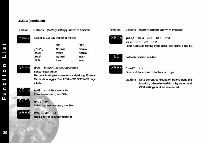
Select SP1/2 LED indicator modes
SP1 SP2[1n.2n] Normal Normal1i.2n Invert Normal1n.2i Normal Invert1i.2i Invert Invert
[0.0] to ±25% sensor maximumSensor span adjustFor recalibrating to a remote standard e.g. ExternalMeter, data logger. See ADVANCED SETTINGS page 24,25.
[0.0] to ±25% sensor f/sZero sensor error, see SPAn
[oFF] onSelect control accuracy monitor
[Var] hi LoRead control accuracy monitor
20
LEVEL 3 (continued)
Function Options [Factory settings] shown in brackets
[Ct A] CT b Ct 1 Ct 2 Ct 3 Ct 4 oS 1 uS oS 2Read Autotune tuning cycle data (see figure, page 14)
Software version number
[nonE] ALLResets all functions to factory settings
Caution: Note current configuration before using this function, otherwise initial configuration and OEM settings must be re-entered.
REU.L TECH
VER
RSETSPAN
ZERO
CHEK
READ
Fu
nc
ti
on
L
is
t
LEVEL 4Access to level 4 is gained through in level 3.Press and hold and
for 10 seconds.
Enter level 4 at Lock , release and together. Display reads
Program security using Lock
Select from three Lock options:
Press and hold , press to index.
LEV.3 locks level 3 and 4 only- Technical Functions.
LEV.2 locks levels 2, 3 and 4 only - Configuration andTechnical Functions.
ALL locks all functions
Note: Locked functions and options may be read.
Function Options [Factory settings] shown in brackets
Press to access following functions
[Auto] StAYProgram mode auto-exit switchAuto-exit returns display to normal if 60 seconds of key inactivity, select StAY to disable
[oFF] onDisable SP2 alarm annunciator -AL-Select on to disable -AL-
dir 1 to 32 [6]Display sensitivitydir = direct display of input1 = maximum, 32 = minimum sensitivity
0.1 to 1.0 [0.5]Derivative sensitivity
21
IMPORTANT NOTE FOR OEM’s: For safety and to protect settings from tamperingUSE THE SOFTWARE SECURITY LOCK.... THEN REMOVE THIS SECTION.
VER
PROG
NO.AL
DIS.S
DER.S
LOCKNONE
LOCKALL
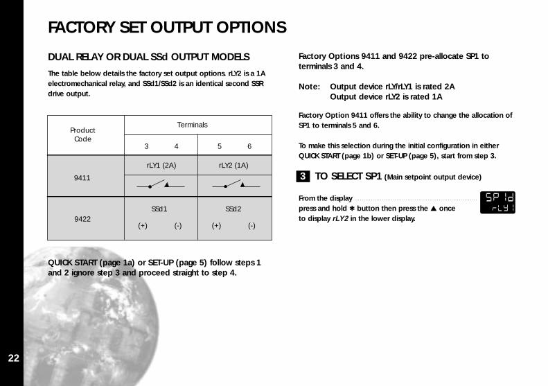
FACTORY SET OUTPUT OPTIONS
22
DUAL RELAY OR DUAL SSd OUTPUT MODELS
The table below details the factory set output options. rLY2 is a 1Aelectromechanical relay, and SSd1/SSd2 is an identical second SSRdrive output.
QUICK START (page 1a) or SET-UP (page 5) follow steps 1and 2 ignore step 3 and proceed straight to step 4.
Factory Option 9411 offers the ability to change the allocation ofSP1 to terminals 5 and 6.
To make this selection during the initial configuration in either QUICK START (page 1b) or SET-UP (page 5), start from step 3.
3 TO SELECT SP1 (Main setpoint output device)
From the displaypress and hold button then press the once to display rLY2 in the lower display.
ProductCode
Terminals
3 4 5 6
9411
9422
rLY1 (2A) rLY2 (1A)
SSd1 SSd2
(+) (-) (+) (-)
Factory Options 9411 and 9422 pre-allocate SP1 toterminals 3 and 4.
Note: Output device rLY/rLY1 is rated 2AOutput device rLY2 is rated 1A
SP1DRLY1
Ad
va
nc
ed
S
et
ti
ng
s
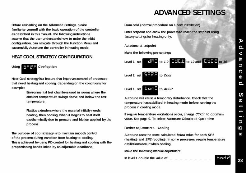
Before embarking on the Advanced Settings, pleasefamiliarise yourself with the basic operation of the controlleras described in this manual. The following instructionsassume that the user understands how to make the initialconfiguration, can navigate through the Function Menu andsuccessfully Autotune the controller in heating mode.
HEAT COOL STRATEGY CONFIGURATION
Using Cool option
Heat-Cool strategy is a feature that improves control of processesthat need heating and cooling, depending on the conditions, forexample:
Environmental test chambers used in rooms where the ambient temperature swings above and below the test temperature.
Plastics extruders where the material initially needs heating, then cooling, when it begins to heat itself exothermically due to pressure and friction applied by theprocess.
The purpose of cool strategy is to maintain smooth controlof the process during transition from heating to cooling.This is achieved by using PID control for heating and cooling with theproportioning bands linked by an adjustable deadband.
From cold (normal procedure on a new installation)
Enter setpoint and allow the process to reach the setpoint usingfactory settings for heating only.
Autotune at setpoint
Make the following pre-settings:
Level 1 set to 1.0 to 10 and to 10
Level 2 set to Cool
Level 1 set to At.SP
Autotune will cause a temporary disturbance. Check that thetemperature has stabilised in heating mode before running theprocess in cooling mode.
If regular temperature oscillations occur, change CYC.t to optimumvalue. See page 9. To select Autotune Calculated Cycle-time
Further adjustments – Cooling
Autotune uses the same calculated bAnd value for both SP1(heating) and SP2 (cooling). In some processes, regular temperatureoscillations occur when cooling.
Make the following manual adjustment:
In level 1 double the value of
ADVANCED SETTINGS
23
SP2.A
DAC
SP2.A
TUNE
CYC.T CYC.2
BND.2
Ad
va
nc
ed
S
et
ti
ng
s
Heat Cool Strategy Configuration (continued)
If no improvement, return to the original value and;
In level 1 halve the value of
If the process hunts between heating and cooling, adeadband setting may be needed. Enter a small value, eg. 1 and observe the process. Increase the setting untilhunting stops.
Level 1 adjust value
Water cooled applications
Water cooled applications operating at temperatures greater than100°C may suffer from the non linear effect caused by water turningto steam. This can be countered by the non linear setting for SP2;
In level 2 set to nL in
Multi zone applications
When tuning multi zone applications like extruders, distortions dueto thermal interaction between adjacent zones can be minimised byrunning autotune on all controllers at the same time.
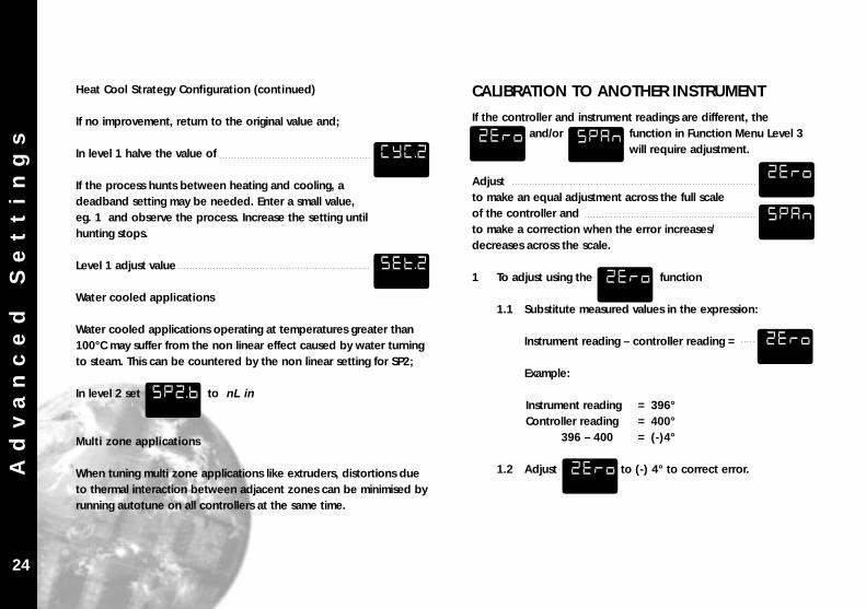
CALIBRATION TO ANOTHER INSTRUMENT
If the controller and instrument readings are different, theand/or function in Function Menu Level 3
will require adjustment.
Adjust to make an equal adjustment across the full scale of the controller andto make a correction when the error increases/decreases across the scale.
1 To adjust using the function
1.1 Substitute measured values in the expression:
Instrument reading – controller reading =
Example:
Instrument reading = 396°Controller reading = 400°
396 – 400 = (-)4°
1.2 Adjust to (-) 4° to correct error.
24
CYC.2ZERO SPAN
ZERO
ZERO
ZERO
ZERO
SPAN
SET.2
SP2.B
Ad
va
nc
ed
S
et
ti
ng
s
2.5 Therefore adjust SPAn to (-) 18 to correct error.
Notes: (1) After making the adjustment the reading will immediately change. Allow time for the temperature to stabilise at T2 before making any further adjustment.At this point, a ZEro adjustment may be needed, referto step 1 above.
(2) Check that the temperature correctly stabilises at T2and then adjust setpoints to T1. If an error is present at T1 repeat from step 2.
LINEAR INPUT CALIBRATION
In addition to the ten temperature inputs, the controller has fivelinear input ranges which can be calibrated to display a range ofengineering units. This procedure involves making adjustments tothe controller’s hi.SC , ZEro and SPAn adjustments found infunction menu levels 2 and 3.
Note: The controllers linear inputs are in mV. If your transducer provides an output in mA this should be converted to mV by feeding the controller input via a high stability one ohm resistor, see figure page 26. Other low Vdc signals can be connected via a suitable voltage divider network to match the controller input requirements.
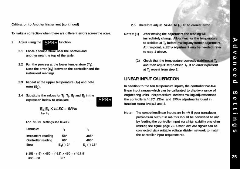
Calibration to Another Instrument (continued)
To make a correction when there are different errors across the scale.
2 Adjust using the function
2.1 Chose a temperature near the bottom andanother near the top of the scale.
2.2 Run the process at the lower temperature (T1).Note the error (E1) between the controller and theinstrument readings.
2.3 Repeat at the upper temperature (T2) and noteerror (E2).
2.4 Substitute the values for T1, T2, E1 and E2 in theexpression below to calculate
E2-E1 X hi.SC = SPAn T2-T1
For hi.SC settings see level 2.
Example: T1 T2
Instrument reading 58° 385°Controller reading 60° 400°Error E1(-) 2° E2 (-) 15°
(-15) - (-2) x 450 = (-13) x 450 = (-)17.9385 - 58 327 25
SPAN
SPAN
Ad
va
nc
ed
S
et
ti
ng
s
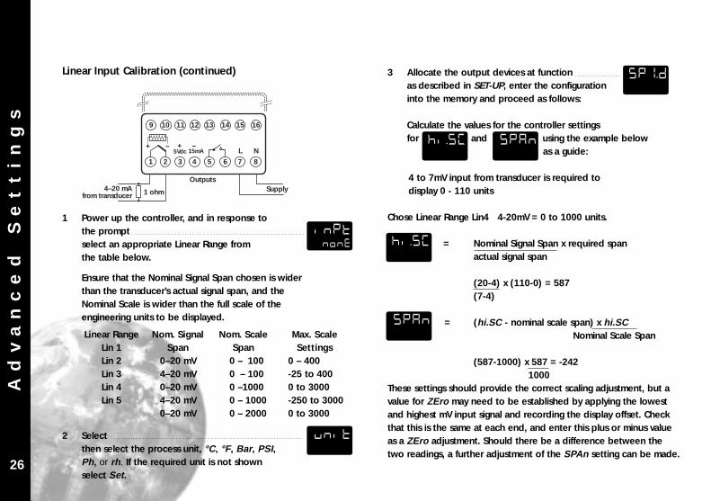
3 Allocate the output devices at functionas described in SET-UP, enter the configurationinto the memory and proceed as follows:
Calculate the values for the controller settings for and using the example below
as a guide:
4 to 7mV input from transducer is required todisplay 0 - 110 units
Chose Linear Range Lin4 4-20mV = 0 to 1000 units.
HI.SC = Nominal Signal Span x required spanactual signal span
(20-4) x (110-0) = 587 (7-4)
SPAN = (hi.SC - nominal scale span) x hi.SCNominal Scale Span
(587-1000) x 587 = -2421000
These settings should provide the correct scaling adjustment, but avalue for ZEro may need to be established by applying the lowestand highest mV input signal and recording the display offset. Checkthat this is the same at each end, and enter this plus or minus valueas a ZEro adjustment. Should there be a difference between thetwo readings, a further adjustment of the SPAn setting can be made.
1 Power up the controller, and in response to the prompt select an appropriate Linear Range from the table below.
Ensure that the Nominal Signal Span chosen is wider than the transducer’s actual signal span, and the Nominal Scale is wider than the full scale of the engineering units to be displayed.
2 Select then select the process unit, °C, °F, Bar , PSI,Ph, or rh . If the required unit is not shown select Set.
Linear RangeLin 1Lin 2Lin 3Lin 4Lin 5
Nom. SignalSpan
0–20 mV4–20 mV0–20 mV4–20 mV0–20 mV
Nom. ScaleSpan
0 – 1000 – 1000 –10000 – 10000 – 2000
Max. ScaleSettings
0 – 400-25 to 4000 to 3000-250 to 30000 to 3000
26
1 2 3 4 5 6 7 8
L N5Vdc 15mA+ – + –
9 10 11 12 13 14 15 16
Supply1 ohm4–20 mAfrom transducer
Outputs
Linear Input Calibration (continued)
INPTNONE
SP1.D
HI.SC
HI.SC
SPAN
SPAN
UNIT
Me
ch
an
ic
al
I
ns
ta
ll
at
io
n
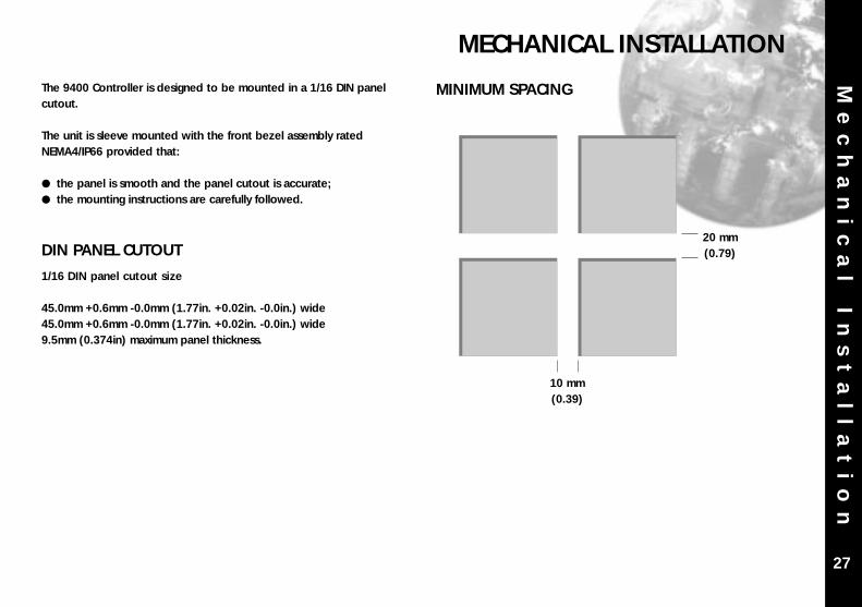
The 9400 Controller is designed to be mounted in a 1/16 DIN panelcutout.
The unit is sleeve mounted with the front bezel assembly ratedNEMA4/IP66 provided that:
the panel is smooth and the panel cutout is accurate; the mounting instructions are carefully followed.
DIN PANEL CUTOUT
1/16 DIN panel cutout size
45.0mm +0.6mm -0.0mm (1.77in. +0.02in. -0.0in.) wide45.0mm +0.6mm -0.0mm (1.77in. +0.02in. -0.0in.) wide9.5mm (0.374in) maximum panel thickness.
MINIMUM SPACING
MECHANICAL INSTALLATION
27
10 mm(0.39)
20 mm(0.79)
Me
ch
an
ic
al
I
ns
ta
ll
at
io
n MOUNTING
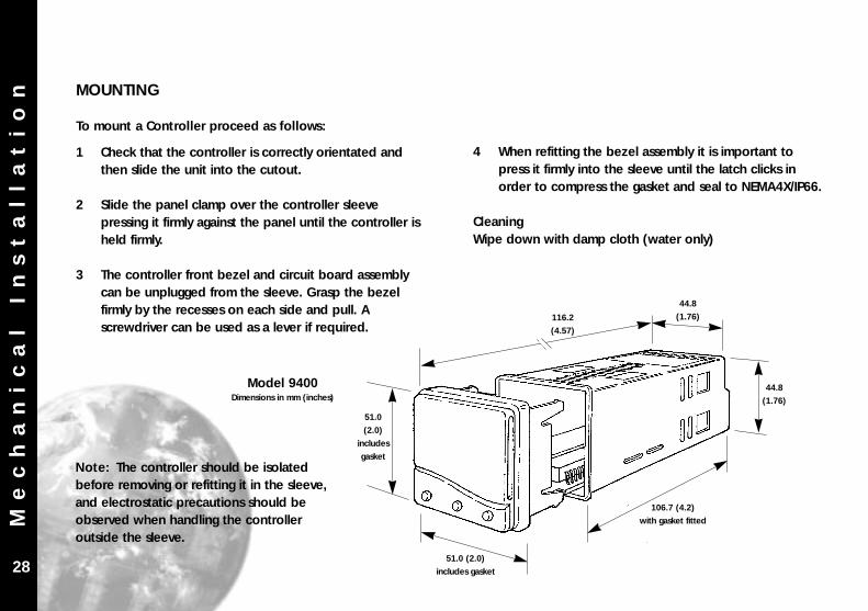
To mount a Controller proceed as follows:
1 Check that the controller is correctly orientated and then slide the unit into the cutout.
2 Slide the panel clamp over the controller sleeve pressing it firmly against the panel until the controller is held firmly.
3 The controller front bezel and circuit board assembly can be unplugged from the sleeve. Grasp the bezel firmly by the recesses on each side and pull. A screwdriver can be used as a lever if required.
4 When refitting the bezel assembly it is important to press it firmly into the sleeve until the latch clicks in order to compress the gasket and seal to NEMA4X/IP66.
CleaningWipe down with damp cloth (water only)
28
44.8
(1.76)
44.8
(1.76)
106.7 (4.2)
with gasket fitted
51.0 (2.0)
includes gasket
51.0
(2.0)
includes
gasket
116.2
(4.57)
Model 9400Dimensions in mm (inches)
Note: The controller should be isolatedbefore removing or refitting it in the sleeve,and electrostatic precautions should beobserved when handling the controlleroutside the sleeve.
El
ec
tr
ic
al
I
ns
ta
ll
at
io
n
OUTPUT DEVICES
Two of the following output devices are fitted to the controllers,depending on the model.
1 Solid state relay drive (SSd/SSd1/SSd2)5Vdc +0/-15%, 15mA non isolatingTo switch a remote SSR (or logic)
2 Miniature power relay (rLY/rLY1)2A/250V resistive, Form A/SPST contacts.
3 Sub miniature power relay (rLY2)1A/250V resistive, Form A/SPST contacts.
OUTPUT DEVICE ALLOCATION
Either of the available outputs may be chosen for the main setpoint(SP1), the remaining device being automatically allocated to thesecond setpoint (SP2).See example illustrated on page 30.
STANDARD MODEL 9400Output Device 1 + Output Device 2
DUAL RELAY MODEL 9411Output Device 2 + Output Device 3
DUAL SSd MODEL 9422Output Device 1 + Output Device 1
Dual relay or dual SSd model options 9411/9422 are fully detailedon page 22.
ELECTRICAL INSTALLATION
29
Designed for use with the following supply voltages:
100 - 240V 50-60 Hz 4.0 VA (nominal)+/-10% maximum permitted fluctuation12V - 24V (AC/DC) +/-20% 4.5 VA Polarity not required
WIRING THE CONNECTOR
Prepare the cable carefully, remove a maximum of 8mm insulationand ideally tin to avoid bridging. Prevent excessive cable strain.Maximum recommended wire size: 32/0.2mm 1.0mm2 (18AWG).
INDUCTIVE LOADS
To prolong relay contact life and suppress interference it isrecommended engineering practice to fit a snubber (0.1uf/100 ohms), refer to illustration on page 30.
CAUTION: Snubber leakage current can cause some electro-mechanicaldevices to be held ON. Check with the manufacturersspecifications.
El
ec
tr
ic
al
I
ns
ta
ll
at
io
n
30
ELECTRICAL INSTALLATION (continued)
EN61010 - /CSA 22.2 No 1010.1 92
Compliance shall not be impaired when fitted to the finalinstallation.
Designed to offer a minimum of Basic Insulation only.
The body responsible for the installation is to ensure thatsupplementary insulation suitable for Installation Category II or III isachieved when fully installed.
To avoid possible hazards, accessible conductive parts of the finalinstallation should be protectively earthed in accordance withEN6010 for Class 1 Equipment.
Output wiring should be within a Protectively Earthed cabinet.
Sensor sheaths should be bonded to protective earth or not beaccessible.
Live parts should not be accessible without the use of a tool.
When fitted to the final installation, an IEC/CSA APPROVEDdisconnecting device should be used to disconnect both LINE andNEUTRAL conductors simultaneously.
A clear instruction shall be provided not to position the equipmentso that it is difficult to operate the disconnecting device.
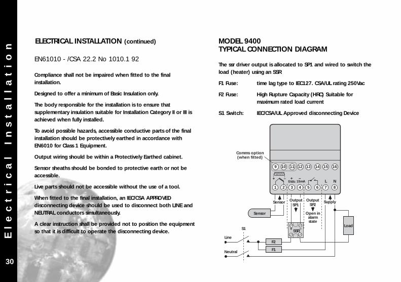
MODEL 9400TYPICAL CONNECTION DIAGRAM
The ssr driver output is allocated to SP1 and wired to switch theload (heater) using an SSR
F1 Fuse: time lag type to IEC127. CSA/UL rating 250Vac
F2 Fuse: High Rupture Capacity (HRC) Suitable for maximum rated load current
S1 Switch: IEC/CSA/UL Approved disconnecting Device
Comms option(when fitted)
1 2 3 4 5 6 7 8
L N5Vdc 15mA+ – + –
12 13 14 15 16
Sensor OutputSP1 SP2
Output
SSR+ –S1
Sensor
Supply
Line
Open inalarmstate
9 10 11
Load
F2
F1Neutral
Se
ns
or
S
el
ec
ti
on
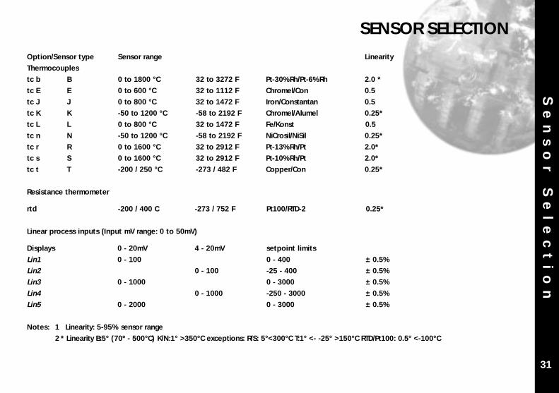
Option/Sensor type Sensor range Linearity
Thermocouples
tc b B 0 to 1800 °C 32 to 3272 F Pt-30%Rh/Pt-6%Rh 2.0 *
tc E E 0 to 600 °C 32 to 1112 F Chromel/Con 0.5
tc J J 0 to 800 °C 32 to 1472 F Iron/Constantan 0.5
tc K K -50 to 1200 °C -58 to 2192 F Chromel/Alumel 0.25*
tc L L 0 to 800 °C 32 to 1472 F Fe/Konst 0.5
tc n N -50 to 1200 °C -58 to 2192 F NiCrosil/NiSil 0.25*
tc r R 0 to 1600 °C 32 to 2912 F Pt-13%Rh/Pt 2.0*
tc s S 0 to 1600 °C 32 to 2912 F Pt-10%Rh/Pt 2.0*
tc t T -200 / 250 °C -273 / 482 F Copper/Con 0.25*
Resistance thermometer
rtd -200 / 400 C -273 / 752 F Pt100/RTD-2 0.25*
Linear process inputs (Input mV range: 0 to 50mV)
Displays 0 - 20mV 4 - 20mV setpoint limits
Lin1 0 - 100 0 - 400 ± 0.5%
Lin2 0 - 100 -25 - 400 ± 0.5%
Lin3 0 - 1000 0 - 3000 ± 0.5%
Lin4 0 - 1000 -250 - 3000 ± 0.5%
Lin5 0 - 2000 0 - 3000 ± 0.5%
Notes: 1 Linearity: 5-95% sensor range
2 * Linearity B:5° (70º - 500°C) K/N:1° >350°C exceptions: R/S: 5°<300°C T:1° <- -25° >150°C RTD/Pt100: 0.5° <-100°C
SENSOR SELECTION
31
Sp
ec
if
ic
at
io
n
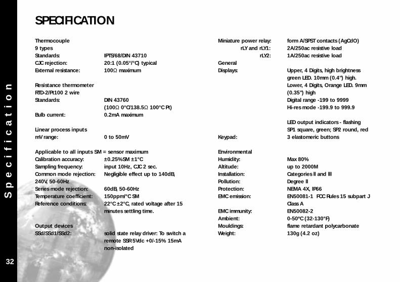
Thermocouple9 typesStandards: IPTS/68/DIN 43710CJC rejection: 20:1 (0.05°/°C) typicalExternal resistance: 100Ω maximum
Resistance thermometerRTD-2/Pt100 2 wireStandards: DIN 43760
(100Ω 0°C/138.5Ω 100°C Pt)Bulb current: 0.2mA maximum
Linear process inputsmV range: 0 to 50mV
Applicable to all inputs SM = sensor maximumCalibration accuracy: ±0.25%SM ±1°CSampling frequency: input 10Hz, CJC 2 sec.Common mode rejection: Negligible effect up to 140dB, 240V, 50-60HzSeries mode rejection: 60dB, 50-60HzTemperature coefficient: 150ppm/°C SMReference conditions: 22°C ±2°C, rated voltage after 15
minutes settling time.
Output devicesSSd/SSd1/SSd2: solid state relay driver: To switch a
remote SSR 5Vdc +0/-15% 15mA non-isolated
Miniature power relay: form A/SPST contacts (AgCdO) rLY and rLY1: 2A/250ac resistive load
rLY2: 1A/250ac resistive loadGeneralDisplays: Upper, 4 Digits, high brightness
green LED. 10mm (0.4”) high. Lower, 4 Digits, Orange LED. 9mm (0.35”) highDigital range -199 to 9999 Hi-res mode -199.9 to 999.9
LED output indicators - flashing SP1 square, green; SP2 round, red
Keypad: 3 elastomeric buttons
EnvironmentalHumidity: Max 80%Altitude: up to 2000MInstallation: Categories ll and lllPollution: Degree llProtection: NEMA 4X, lP66EMC emission: EN50081-1 FCC Rules 15 subpart J
Class AEMC immunity: EN50082-2Ambient: 0-50ºC (32-130°F)Mouldings: flame retardant polycarbonateWeight: 130g (4.2 oz)
SPECIFICATION
32

QUICK START
After power-up the controller requires programming with thefollowing information:
Type of Sensor (See list of temperature sensors p.31)Operating unit (See list of units p.18)Allocation of Output Device to SP1/SP2 (Relay or SSd)Temperature Setpoint eg. Degrees
When the above information has been programmed into thecontroller it will be operational with the following factory settings.
Proportional band/Gain 10ºC/18ºFIntegral time/Reset 5 minsDerivative time/Rate 25 secs
Proportional cycle-time 20 secs (Typical setting for relay output)DAC Derivative approach control 1.5(Average setting for minimum overshoot)
NB: Please note that in program mode, Functions are shown inthe upper display (green) and Options in the lower display(orange).
Qu
ic
k
St
ar
t
Note: In this manual the letter k is represented by thecharacter K
Copyright CAL Controls Ltd. 1997
Not to be reproduced without prior written permission fromCAL Controls Ltd. Whilst every effort has been made to ensurethe accuracy of the specifications contained in this manual,due to our policy of continuous develpment, CAL Controls Ltdreserves the right to make changes without prior notice.
1a
Note: During the following procedure the display will revert toafter 60 seconds of key inactivity, but will retain any settings already completed. Should this occur, or in the event of becoming ‘lost’ in the program, please start again checking any settings completed so far.
QUICK START SET-UP
On power-up the controller will display the self test
sequence followed by the initial display
1 Select input sensor.
Press and hold and use the or buttons to
scroll through the sensor selection list
until the correct sensor is displayed.
Release the buttons. The display now
read selected sensor type e.g.
Press once The display will now read
TUNEPARK
INPTNONE
INPTNONE
INPTTC.S
UNITNONE

Operating Manual
CAL ControlsTemperature Controllers
CAL ControlsTemperature Controllers
CAL Controls LtdBury Mead Road, Hitchin, Herts, SG5 1RT. UK
Tel: + 44 (0)1462-436161 Fax: + 44 (0)1462-451801email: [email protected]
http://www.cal-controls.com
CAL Controls Inc1580 S.Milwaukee Avenue, Libertyville, IL 60048. USA
Tel: (847) 680-7080 Fax: (847) 816-6852
000M06/33014/1/0798
CAL 9400 Dual DisplayAutotune Temperature
Controller