caged 249 series displacer sensors - linear...
TRANSCRIPT

D20
0099
X01
2
Caged 249 Series Displace r SensorsContents
Introduction 1. . . . . . . . . . . . . . . . . . . . . . . . . . . . . . . Scope of Manual 1. . . . . . . . . . . . . . . . . . . . . . . . . . . . . Description 1. . . . . . . . . . . . . . . . . . . . . . . . . . . . . . . . . . Type Number Description 2. . . . . . . . . . . . . . . . . . . . .
Maintenance 3. . . . . . . . . . . . . . . . . . . . . . . . . . . . . . Cleaning the Cage 4. . . . . . . . . . . . . . . . . . . . . . . . . . . Removing the Displacer and Stem 4. . . . . . . . . . . . . Replacing the Displacer, Cotter Spring, Stem
End Piece, and Displacer Spud 5. . . . . . . . . . . . . . Replacing the Displacer Rod/Driver Assembly 6. . . Replacing the Torque Tube 6. . . . . . . . . . . . . . . . . . . . Changing Cage Head Position 7. . . . . . . . . . . . . . . . . Replacing the Torque Tube Arm and
Changing the Mounting 8. . . . . . . . . . . . . . . . . . . . .
Parts Ordering 8. . . . . . . . . . . . . . . . . . . . . . . . . . . .
Parts Kits 9. . . . . . . . . . . . . . . . . . . . . . . . . . . . . . . . .
Parts List 9. . . . . . . . . . . . . . . . . . . . . . . . . . . . . . . . . .
Introduction
Scope of ManualThis instruction manual includes maintenance andparts ordering information for the caged 249 Seriessensors.
Although a Type 249 Series sensor is usually shippedwith attached controller or transmitter, this manualdoes not include operation, installation, calibration,maintenance, and parts ordering information for thecontroller/transmitter or for the complete unit. For thisinformation, refer to the appropriate controller/trans-mitter instruction manual. Note that a shipping rod andmetal block must be removed from each end of thedisplacer cage before installation.
Figure 1. Type 249B Sensor with 2500 Series Controller
W3121-3/IL/A
Only personnel qualified through training or experienceshould install, operate, and maintain the sensor andattached controller or transmitter. If there are anyquestions concerning these instructions, contact yourFisher Controls sales office or representative beforeproceeding.
DescriptionThe 249 Series sensors are designed to measure liq-uid level, interface level, or density/specific gravity in-side a vessel.
A torque tube assembly (figure 2) and displacer pro-vide an indication of liquid level, interface level, or den-sity/specific gravity. The torque tube assembly con-sists of a hollow torque tube with a shaft welded insideit at one end and protruding from it at the other end.
Instruction ManualForm 1802July 1995 Caged 249 Series
Caged 249 Series
2
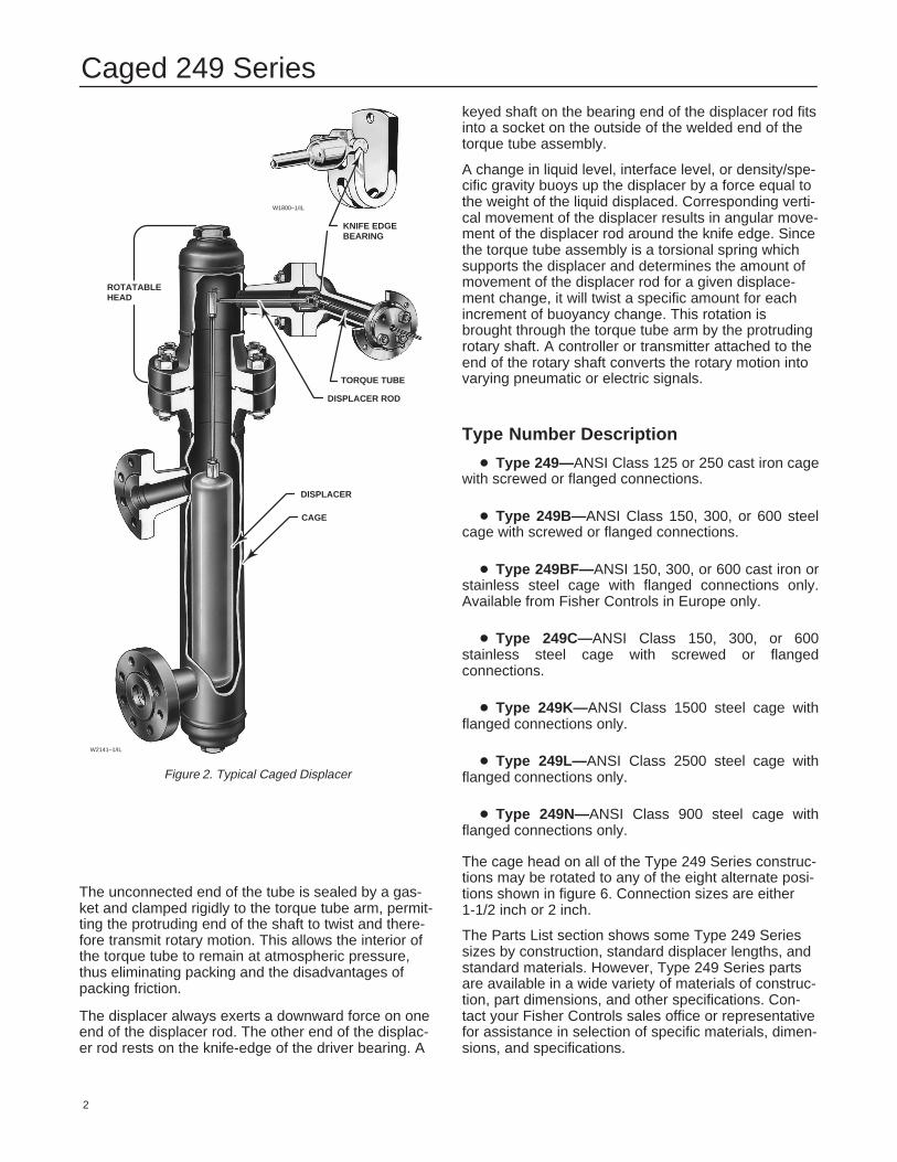
Figure 2. Typical Caged Displacer
W1800–1/IL
W2141–1/IL
KNIFE EDGE BEARING
TORQUE TUBE
DISPLACER ROD
ROTATABLEHEAD
DISPLACER
CAGE
The unconnected end of the tube is sealed by a gas-ket and clamped rigidly to the torque tube arm, permit-ting the protruding end of the shaft to twist and there-fore transmit rotary motion. This allows the interior ofthe torque tube to remain at atmospheric pressure,thus eliminating packing and the disadvantages ofpacking friction.
The displacer always exerts a downward force on oneend of the displacer rod. The other end of the displac-er rod rests on the knife-edge of the driver bearing. A
keyed shaft on the bearing end of the displacer rod fitsinto a socket on the outside of the welded end of thetorque tube assembly.
A change in liquid level, interface level, or density/spe-cific gravity buoys up the displacer by a force equal tothe weight of the liquid displaced. Corresponding verti-cal movement of the displacer results in angular move-ment of the displacer rod around the knife edge. Sincethe torque tube assembly is a torsional spring whichsupports the displacer and determines the amount ofmovement of the displacer rod for a given displace-ment change, it will twist a specific amount for eachincrement of buoyancy change. This rotation isbrought through the torque tube arm by the protrudingrotary shaft. A controller or transmitter attached to theend of the rotary shaft converts the rotary motion intovarying pneumatic or electric signals.
Type Number Description
� Type 249—ANSI Class 125 or 250 cast iron cagewith screwed or flanged connections.
� Type 249B— ANSI Class 150, 300, or 600 steelcage with screwed or flanged connections.
� Type 249BF— ANSI 150, 300, or 600 cast iron orstainless steel cage with flanged connections only.Available from Fisher Controls in Europe only.
� Type 249C—ANSI Class 150, 300, or 600stainless steel cage with screwed or flangedconnections.
� Type 249K— ANSI Class 1500 steel cage withflanged connections only.
� Type 249L— ANSI Class 2500 steel cage withflanged connections only.
� Type 249N—ANSI Class 900 steel cage withflanged connections only.
The cage head on all of the Type 249 Series construc-tions may be rotated to any of the eight alternate posi-tions shown in figure 6. Connection sizes are either1-1/2 inch or 2 inch.
The Parts List section shows some Type 249 Seriessizes by construction, standard displacer lengths, andstandard materials. However, Type 249 Series partsare available in a wide variety of materials of construc-tion, part dimensions, and other specifications. Con-tact your Fisher Controls sales office or representativefor assistance in selection of specific materials, dimen-sions, and specifications.

Caged 249 Series
3
Maintenance
WARNING
Avoid personal injury or property dam-age resulting from the sudden release ofpressure. Before performing any mainte-nance procedure, relieve any processpressure in the vessel where the Type249 sensor is installed. Drain the pro-cess liquid from the vessel. Shut off anyelectrical or pneumatic input to the con-troller or transmitter attached to theType 249 sensor and vent any pneumat-ic supply pressure. Use caution whenloosening flange bolting (key 22) or pipeplugs (key 17, 26, or 27).
Remove the controller or transmitterfrom the torque tube arm (key 3).
Before continuing with any maintenanceprocedure, be sure the cage (key 1) isalso free of process pressure and/or liq-uid. Use caution when loosening flangebolting (key 22) or pipe plugs (key 17,26, or 27).
Before performing any maintenance pro-cedure requiring the handling of the dis-placer, inspect the displacer (key 10) tomake sure process pressure or liquidshave not penetrated the displacer.
The displacer in this unit is a sealedcontainer. If penetrated by process pres-sure or liquid, the displacer may holdpressure or hazardous liquid for an ex-tended period. A displacer that has beenpenetrated by process pressure or liq-uid may contain:
� pressure as a result of being in apressurized vessel
� liquid that becomes pressurizeddue to a change in temperature
� liquid that is flammable, toxic, cor-rosive, or reactive
Sudden release of pressure, contactwith hazardous liquid, fire, or explosion,which might result in personal injury orproperty damage, can occur if a displac-er that is retaining pressure or processliquid is punctured, subjected to heat,or repaired.
Handle the displacer with care. Considerthe characteristics of the specific pro-cess liquid in use.
Figure 3. Piezometer Ring Cage Mounted in Flow Line
A6620/IL
Note
Except for gaskets (keys 13 and 14),trouble symptoms peculiar to specificparts are discussed in the following sec-tions. Each section is specific to theseparts. Regardless of location, gasketfailure is indicated by leakage in thegasket area. Every time a gasket is re-moved, replace it with a new one uponreassembly.
The procedures below apply to all sensor types exceptwhere indicated. Key numbers used are shown in thefollowing illustrations:
Type 249—Figure 7
Type 249B— Figure 8
Type 249C—Figure 9
Type 249K— Figure 10

Caged 249 Series
4
Type 249L— Figure 11
Type 249N—Figure 12
Sensor parts are subject to normal wear and must beinspected and replaced as necessary. The frequencyof inspection and replacement depends upon the se-verity of service conditions.
Because of the care Fisher Controls takes in meetingall manufacturing requirements (heat treating, dimen-sional tolerances, materials of construction, and otherproduct characteristics specified by Fisher Controls),use only replacement parts manufactured or furnishedby Fisher Controls.
Cleaning the CageProcess residue buildup in the bottom of the cage (key1) or at the connections may restrict flow in and out ofthe cage or interfere with displacer motion. Removethe cage to clean out process residue buildup.
1. Before starting any maintenance procedure, besure the following safety actions have been com-pleted.
� Relieve process pressure in the vessel where theType 249 sensor is installed.
� Drain the process liquid from the vessel.
� Shut off any electrical or pneumatic input to thecontroller or transmitter attached to the Type 249 sensorand vent any pneumatic supply pressure. Remove thecontroller or transmitter from the torque tube arm (key 3).Take care not to damage the torque tube assembly (key9) inside the torque tube arm.
� Be sure the cage is also free of process pressureand/or liquid. Use caution when loosening flange bolting(key 22) or pipe plugs (keys 17, 26, or 27).
� Be sure process pressure or liquids have notpenetrated the displacer (key 10).
2. Properly support the cage head (key 2) and thetorque tube arm. Remove the cap screws or stud bolts(key 21) and hex nuts (key 22) that hold the cagehead to the cage.
CAUTION
When removing a sensor from a cage,the displacer may remain attached tothe displacer rod and be lifted out withthe cage head when the cage head isremoved. If separating the displacer anddisplacer rod before removing the cage
head, remove the cotter spring (key 11).Be careful not to let the displacer slipand drop into the bottom of the cage, asdisplacer damage could result.
3. Carefully remove the cage head and lift out the dis-placer.
4. A style 1 or 4 (screwed or flanged) cage must bedisconnected at the lower connection and the liquiddamper (key 29) removed. Remove the damper byprying it out of a flanged connection or by unscrewingit from a screwed connection with a 1/2-inch hex (Al-len) wrench. If necessary, completely remove the style4 cage from the vessel.
5. For complete drainage and cleaning of a cage withstyle 2 or 3 (screwed or flanged) connections (figure4), remove the pipe plug (keys 17 or 26) from the bot-tom of the cage. Remove the liquid damper (key 29). Ifnecessary, completely remove the cage from the ves-sel.
6. Use appropriate cleaning techniques, tools, andsolutions. After cleaning the cage, install the liquiddamper and reconnect the cage to the vessel. Installthe cage head and controller/transmitter. Properly cali-brate the controller/transmitter following the proce-dures given in the controller/transmitter instructionmanual.
Removing the Displacer and StemThe displacer (key 10) is a sealed container. If the dis-placer has been penetrated by process pressure orliquid, it may hold pressure or hazardous liquid for anextended period.
Process residue buildup on the displacer and stem(key 24) may change displacer weight or displace-ment. A bent stem or a dented or corroded displacercan impair performance.
If the displacer rests against the travel stop, appearsto be overweight, or causes output drift or other outputinaccuracies, it may have been penetrated by processpressure or liquid. Such a displacer may contain pres-sure because it was in a pressurized vessel, may con-tain process liquid that becomes pressurized due to achange in temperature, and may contain process liq-uid that is flammable, toxic, corrosive, or reactive.Sudden release of pressure, contact with hazardousliquid, fire, or explosion, which may result in personalinjury or property damage, can occur if a displacer thatis retaining pressure or process liquid is punctured,subjected to heat, or repaired.
Handle the displacer with care:
1. Before starting any maintenance procedure, besure the following safety actions have been com-pleted.

Caged 249 Series
5
� Relieve process pressure in the vessel where theType 249 sensor is installed.
� Drain the process liquid from the vessel.
� Shut off any electrical or pneumatic input to thecontroller or transmitter attached to the Type 249 sensorand vent any pneumatic supply pressure. Remove thecontroller or transmitter from the torque tube arm.
� Be sure the cage is also free of process pressureand/or liquid. Use caution when loosening flange boltingor pipe plugs.
� Be sure process pressure or liquids have notpenetrated the displacer.
2. Properly support the cage head or sensor head(key 2) and the torque tube arm (key 3). Remove thecap screws or stud bolts (key 21) and hex nuts (key22) that hold the cage head to the cage.
CAUTION
When removing the sensor from thecage, the displacer may remain attachedto the displacer rod and be lifted outwith the cage head (key 2) when thecage head is removed. If separating thedisplacer and displacer rod/driveassembly (key 9) before removing thecage head, remove the cotter spring(key 11). Be careful not to let thedisplacer slip and drop into the bottomof the cage, as displacer damage couldresult.
3. When removing the sensor from the cage, the dis-placer may remain attached to the displacer rod andbe lifted out with the cage head (key 2) when the cagehead is removed. If separating the displacer and dis-placer rod/driver assembly (key 9) before removing thecage head, remove the cotter spring (key 11) accord-ing to the Replacing the Displacer, Cotter Spring,Stem End Piece, and Displacer Spud section. Becareful not to let the displacer slip and drop into thebottom of the cage, as displacer damage could result.
4. Carefully remove the cage head and lift out the dis-placer (key 10). If the displacer comes out with thecage head, be careful not to damage the displacer orbend the stem when setting the cage head down.
5. Follow the procedure for replacing the displacer,displacer rod assembly, cotter spring, stem end piece,and displacer spud as necessary.
A1271–2/IL
Figure 4. Cage Connection Styles
Replacing the Displacer, Cotter Spring,Stem End Piece, and Displacer SpudThe cotter spring (key 11), the ball on the displacerrod/driver assembly (key 7), and the stem end piece(key 23) or displacer spud socket may be either tooworn for a secure connection or so clogged or cor-roded that the displacer does not pivot properly. Re-place these parts, as necessary.
CAUTION
If the displacer is to be disconnectedfrom the displacer rod before beingremoved from the cage, provide asuitable means of supporting thedisplacer to prevent it from droppinginto the cage and being damaged.
1. After following the proper procedure to remove thecage head and the displacer from the cage, move the

Caged 249 Series
6
sensor assembly to a suitable maintenance area.Properly support the assembly to avoid damage to thedisplacer, displacer stem, displacer rod/driver assem-bly, and associated parts.
2. Reach the cotter spring, displacer spud, ball end ofthe displacer rod/driver assembly, stem end piece, ordisplacer stem connector as follows:
� All sensors with style 1 or 2 (screwed orflanged) connections —through the top connection.
� Type 249L sensors with style 3 or 4 (screwed orflanged) connections —by removing the hex nuts (key33), flange (key 30), and ring (key 31).
� All other sensors with style 3 or 4 (screwed orflanged) connections —by removing the top pipe plug(key 26).
3. Remove the cotter spring to free the displacer orstem end piece from the ball end of the displacer rod/driver assembly. Lift the displacer or stem end piecefrom the ball.
4. Replace worn or damaged parts as necessary. Re-turn the displacer or stem end piece to the displacerrod/driver assembly. Install the cotter spring.
5. If necessary, clean the cage following the proce-dure in this manual. Install the cage head and control-ler/transmitter. Properly calibrate the controller/trans-mitter following the procedures given in thecontroller/transmitter instruction manual.
Replacing the Displacer Rod/DriverAssemblyThe ball on the displacer rod/driver assembly (key 7)may be either too worn for a secure connection or socorroded that the displacer does not pivot properly.Replace the displacer rod/driver assembly, if neces-sary.
CAUTION
If the displacer is to be disconnectedfrom the displacer rod/driver assemblybefore being removed from the cage,provide a suitable means of supportingthe displacer to prevent it from droppinginto the cage and being damaged.
1. After following the proper procedure to remove thecage head and the displacer from the cage, move thesensor assembly to a suitable maintenance area.Properly support the assembly to avoid damage to the
displacer, displacer stem, displacer rod assembly, andassociated parts.
2. Remove the controller/transmitter and displacer(key 10). Then, remove the hex nuts (key 20) that holdthe torque tube arm (key 3) to the cage head (key 2).Separate the torque tube arm from the cage head.
3. Using the proper tool, loosen and then remove theupper bearing driver bolt (key 5). Lift the displacer rod/driver assembly from the knife edge of the driver bear-ing (key 4). Separate the displacer rod/driver assemblyfrom the end of the torque tube assembly (key 9).
4. If necessary, remove the bearing driver by remov-ing the lower bearing driver bolt. Install a fresh bearingdriver and bolts.
5. If necessary, replace the displacer rod/driver as-sembly and install it on the knife edge of the bearingdriver. Carefully fit the keyed shaft on the bearing endof the displacer rod into a socket on the outside of thewelded end of the torque tube assembly.
6. If necessary, clean the cage following the proce-dure in this manual. Install the cage head and control-ler/transmitter. Properly calibrate the controller/trans-mitter following the procedures given in thecontroller/transmitter instruction manual.
Replacing the Torque TubeCorrosion or leakage through the outer end of thetorque tube is evidence of deterioration in the torquetube assembly (key 9) or torque tube end gasket (key14). Erratic or nonexistent rotary shaft output may oc-cur if the socket on the inner end of the torque tubeassembly does not engage the bearing end of the dis-placer rod assembly (key 7).
1. After following the proper procedure to remove thecage head and the displacer from the cage, move thesensor assembly to a suitable maintenance area.Properly support the assembly to avoid damage to thedisplacer, displacer stem, displacer rod assembly, andassociated parts.
2. Remove the controller/transmitter and displacer(key 10). Then, remove the hex nuts (key 20) that holdthe torque tube arm (key 3) to the cage head (key 2).Separate the torque tube arm from the cage head.
3. Remove the nuts (key 18) and retaining flange (key6) holding the positioning plate (key 8) at the end ofthe torque tube arm.
CAUTION
If the displacer is still attached to thedisplacer rod at this point, be carefulnot to let the torque tube assembly slip

Caged 249 Series
7
Figure 5. Torque Tube and Displacer Rod Assemblies
W0654-1/IL
������ � � ������� � � ����� ����� ������ � � ������� � � ����� �����
DISPLACER RODASSEMBLY
ROTARY SHAFT
TORQUE TUBE
OUTER TUBE END
POSITIONING PLATE
DRIVER BEARINGW0145-1/IL
when using the screwdriver leverageprocedure in steps 4 and 6. Suddenrelease of the displacer could causedamage.
4. Remove the positioning plate (key 8) by freeing itstwo lugs.
The vertical lug fits into a hole in the flange of thetorque tube arm (top of figure 5, left). The horizontallug (hidden behind the screwdriver at the bottom offigure 5, left) fits into a slot in the outer tube end of thetorque tube assembly (the figure 5 exploded viewshows this lug to the right of the outer tube end).
The positioning plate may be pried away from thetorque tube arm and outer tube end if the displaceralready has been disconnected from the displacer rod.However, if the displacer is still connected to the dis-placer rod, place a screwdriver blade in the slots of thepositioning plate and outer tube end as shown in figure5. Slowly turn the positioning plate to release its lugfrom the torque tube arm. Then carefully turn the plateback to allow the displacer to come to rest, and slipthe other lug of the plate from its slot in the outer tubeend.
5. Pull the torque tube assembly and tube end gasketout of the torque tube arm.
6. Install a new tube end gasket and insert the torquetube assembly into the torque tube arm as shown infigure 5. Rotate the torque tube assembly until itssocket mates with the driver member on the displacerrod assembly and so that the outer tube flange restsagainst the gasket. With a thumb on the upper portionof the positioning plate and a screwdriver in the slotsas shown in figure 5, rotate the plate and press the lugon the plate into the hole in the torque tube arm.
7. Install the retaining flange and secure it with fournuts (key 18), being sure to tighten all nuts evenly.
8. If necessary, clean the cage following the proce-dure in this manual. Install the cage head and control-ler/transmitter. Properly calibrate the controller/trans-mitter following the procedures given in thecontroller/transmitter instruction manual.
Changing Cage Head PositionThe cage head (key 2) may be mounted so that thetorque tube arm (key 3) is in any one of eight alternatepositions around the cage as shown in figure 6. Nei-ther the displacer nor the torque tube arm need beremoved when head position is changed.
1. Before starting any maintenance procedure, besure the following safety actions have been com-pleted.
� Relieve process pressure in the vessel where theType 249 sensor is installed.
� Drain the process liquid from the vessel.
� Shut off any electrical or pneumatic input to thecontroller or transmitter attached to the Type 249 sensorand vent any pneumatic supply pressure. Remove thecontroller or transmitter from the torque tube arm.
� Be sure the cage is also free of process pressureand/or liquid. Use caution when loosening flange boltingor pipe plugs.
� Be sure process pressure or liquids have notpenetrated the displacer.
2. Remove the hex nuts (keys 20 or 22) from the bolt-ing (key 21) and reposition the head as desired.

Caged 249 Series
8
Figure 6. Cage Head Mounting Positions
AH9150–AA2613–2/IL
Replacing the Torque Tube Arm andChanging the Mounting1. Looseness of the driver bearing (key 4); wear on itsknife-edged surface; or a bent, worn, or corroded dis-placer rod assembly (key 7) may impair performance.Be especially sure to check the ball on the displacerrod.
2. After following the proper procedure to remove thecage head and the displacer from the cage, move thesensor assembly to a suitable maintenance area.Properly support the assembly to avoid damage to thedisplacer, displacer stem, displacer rod assembly, andassociated parts.
3. Remove the controller/transmitter and displacer(key 10). Then, remove the hex nuts (key 20) that holdthe torque tube arm (key 3) to the cage head (key 2).Separate the torque tube arm from the cage head.
4. Follow the proper procedure to remove the torquetube assembly (key 9).
5. Remove the bearing bolts (key 5), displacer rodassembly, and driver bearing.
6. Determine the new mounting orientation.
Note
Be sure that the driver bearing will beinstalled so that its knife edge is point-ing up when the torque tube arm ismounted in the desired orientation (fig-ure 6). Since changing the mountingposition of the torque tube arm by 180 �
will change controller or transmitter ac-tion from direct to reverse or vice versa,the controller/transmitter action must bereversed from what it was before themounting method was changed.
7. Install the driver bearing, displacer rod assembly,and bearing bolts (key 5) into the torque tube arm.Install a new arm gasket. Install the torque tube arm inthe desired mounting position on the cage head andsecure it with the proper bolting (keys 19 and 20).
8. Install the torque tube assembly. Install the displac-er.
9. If necessary, clean the cage following the proce-dure in this manual. Install the cage head and control-ler/transmitter. Properly calibrate the controller/trans-mitter following the procedures given in thecontroller/transmitter instruction manual.
Parts OrderingWhenever corresponding with your Fisher Controlssales office or representative about this equipment,always mention the sensor serial number. Each sen-sor is assigned a serial number which is stamped on anameplate (key 54, not shown) attached to the torquetube arm. This same number also appears on the con-troller/transmitter nameplate when a complete control-ler/transmitter-sensor unit is shipped from the factory.When ordering a replacement part, be sure to includethe 11-character part number from the following partslist.

Caged 249 Series
9
Parts Kits
Key Description Part NumberSENSOR PARTS KIT
Kit contains keys 9, 11, 12, 13, 14For Type 249
Kit includes 1 cage gasket (key 12) for Type249 class 125 and 1 cage gasket (key 12) forType 249 Class 250 R249X000022
For Type 249B R249BX00012
Parts List
Key Description Part Number
Sensor Common Parts1 Cage
(If a part number is required, contact your Fisher Controls sales office or representative.)
2 Cage Head(If a part number is required, contact your Fisher Controls sales office or representative.)
3 Torque Tube Arm(If a part number is required, contact your Fisher Controls sales office or representative.)
4 Driver Bearing(1), S31600 1K5395 360425 Driver Bearing Bolt(1), S31600 (2 req’d) 1K5394 350726 Retaining Flange
(If a part number is required, contact your Fisher controls sales office or representative.)
7 Rod/Driver Assy(1), S31600 stainless steel (SST)Type 249 and 249B 1B5461 000A2Type 249CStandard wall torque tube 1F9579 000A2Heavy wall torque tube 1J8281 X0012
Type 249K 1C6151 000A2Type 249L 1B5698 000A2Type 249N 1C6151 000A2
8 Positioning Plate, Steel 1B8123 250829* Torque Tube Assy(1)
Type 249 and 249BN05500 (Nickel Alloy, K-Monel)Standard wall 1K4493 X0012Thin wall 1K4495 X0012Heavywall 1K4497 X0012
Type 249CS31600Standard wall 1K4505 000A2Heavy wall 1K4503 000A2
Type 249K, 249L, and 249NN05500 (Nickel Alloy, K-Monel)Standard wall 1K4499 X0012Thin wall 1K4501 X0012
10 Displacer(1)
TYPE 249 and 249B3 X 14 Inches (1600 PSI), S30400 15A3848 X0122 X 32 Inches (1500 PSI), S31600 15A4586 X0221-5/8 X 48 Inches (1800 PSI), S30400 15A5007 X0221-1/2 X 60 Inches (1800 PSI), S30400 15A5017 X0421-3/8 X 72 Inches (1400 PSI), S30400 1C1685 000A2
Type 249C1-1/2 X 32 Inches (1300 PSI), S31600 15A4556 X0222-3/8 X 14 Inches (1400 PSI), S31600 15A4547 X052
Key Description Part Number10 Displacer(1) (continued)
Type 249K1-3/4 X 32 Inches (4200 PSI), S30400 15A4666 X0322-3/4 X 14 Inches (6000 PSI), S30400 1L7548 000A2
Type 249L2-3/4 X 14 Inches (6000 PSI), S30400 1L7548 000A2
Type 249N1-29/32 X 32 Inches (3400 PSI), S30400 15A4581 X0422-7/8 X 14 Inches (4000 PSI), S30400 1L9152 000A2
11* Cotter Spring(1), N04400 (Monel) (2 req’d) 1A5179 4202212* Gage Gasket(1)
Type 249, Graphite-stainless steel(Unless otherwise noted)Class 125 0Y0944 X0032Class 250 0Y0945 X0032
Type 249B 0Y0873 X0082Type 249C 1F8305 X0062Type 249K, composition-stainless steel 1N9242 99152Type 249N 0U0365 X0032
12* Ring (Iron gasket)Type 249L only 1N9461 21992
13* Arm Gasket(1)
Type 249, 249B, and 248CGraphite-stainless steel 1E5629 X0072
Type 249K , composition-stainless steel 1N9243 99152Type 249N Graphite-stainless steel 1A1297 X0022
13* Ring (Iron gasket)Type 249L only 1A4455 21992
14* Tube End Gasket(1)
Type 249, 249B, 249C, 249K, 249L, and 249NGraphite-stainless steel 0Y0876 X0052
14* Outer End Gasket(1)
Type 249LGraphite-stainless steel 0Y0876 X0052
15 Stud Bolt(1) (4 req’d)Type 249, Steel B7 12A8835 X132Type 249B and 249C, Steel B7 12A8835 X132Type 249K, 249L, and 249N, Steel B7 1K6235 X0022
16 Groove Pin, S31600 1A3618 28992
Note
For Key 17 see Figure 4: Two styles of vessel/cageconnections are available: screwed (S) and flanged (F).Four connection configurations are available:
� 1, top and bottom of cage
� 2, top and lower side of cage
� 3, side of cage only
� 4, upper side and bottom of cage
Styles 1, 2, 3, 4 refer to either screwed or flanged.Styles S1, S2, S3, S4 refer to screwed connections.Styles F1, F2, F3, F4 refer to flanged connections.
17 Pipe Plug(1)
For 249B , styles 2, 3, steel 1A7715 28992For 249C, styles 2, 3, S31600 1A3692 35072For 249K, 249L, 249N , styles 2, 3, steel 1A3692 24492
18 Hex Nut(1) (4 req’d)For 249, 249B, and 249C , steel-B7 1A3773 24072For 249K, 249L, 249N , steel B7 1A3772 24072
19 Cap Screw(1), steel B7 (4 req’d)For 249Class 125 1A5147 X0022Class 250 1A9362 X0042
*Recommended spare part.1. This part is available in a wide variety of materials of construction, part dimensions,or other specifications. Listed here are standard or typical materials, dimensions, orspecifications. Contact your Fisher Controls sales office or representative for assis-tance in selection of specific materials, dimensions, or specifications.

Caged 249 Series
10
Figure 7. Type 249 sensor construction
30A1913-B/DOC30A7422-B/DOC

Caged 249 Series
11
Figure 8. Type 249B Sensor Construction
30A1914-D/DOC
30A1915-C/DOC
���� �� ���� � � � ����������
������ ���
Key Description Part Number19 Bolt Stud(1), steel B7 (4 req’d)
For 249B, 249C 1A3544 31012For 249K, 249N 1A3771 31012
20 Hex Nut(1), steelFor 249Class 125 (12 req’d) 1A3772 24072Class 250 (4 req’d) 1A3433 X0042
For 249B, 249C (8 req’d) 1A3760 24072For 249K, 249N (8 req’d) 1C1727 24082For 249L (4 req’d) 1A4452 24072
21 Cap Screw(1), steel B7 (8 req’d)For 249Class 125 12B5478 X012Class 250 1A3534 X0042
Key Description Part Number21 Bolt Stud(1), B7 (8 req’d)
For 249B 1A3543 31012For 249C 1A8835 31012For 249K 1C7725 31012For 249L 1A5010 31012For 249N 1A3657 31012
22 Hex Nut(1), steelFor 249Class 250 (8 req’d) 1A3681 X0032
For 249B (16 req’d) 1A3520 24072For 249C (8 req’d) 1A3374 24072For 249K (8 req’d) 1A4409 24072For 249L (16 req’d) 1A5011 24072For 249N (8 req’d) 1C1727 24082
1. This part is available in a wide variety of materials of construction, part dimensions,or other specifications. Listed here are standard or typical materials, dimensions, orspecifications. Contact your Fisher Controls sales office or representative for assis-tance in selection of specific materials, dimensions, or specifications.

Caged 249 Series
12
Figure 9. Type 249C Sensor Construction
30A7425-B/DOC30A7428-B/DOC
Key Description Part Number23 Displacer Stem End Piece(1), S31600 1A3933 35072
NoteFor Key 24 see Figure 4: Two styles of vessel/cageconnections are available: screwed (S) and flanged (F).Four connection configurations are available:
� 1, top and bottom of cage
� 2, top and lower side of cage � 3, side of cage only
� 4, upper side and bottom of cageStyles 1, 2, 3, 4 refer to either screwed or flanged.Styles S1, S2, S3, S4 refer to screwed connections.Styles F1, F2, F3, F4 refer to flanged connections.
Key Description Part Number24 Displacer Stem(1), S31600
For 249 1E7845 35072For 249B 1E7488 35072For 249C 1N3635 35072For 249K (styles F3, F4 only) 1L9162 35072For 249L (styles F1, F2 only) 1N9591 35072For 249L (styles F3, F4 only) 1P6885 35162For 249N (styles F3, F4 only) 1L9162 35072
25 Hex Nut(1), B8M (2 req’d) 1A3915 35252
1. This part is available in a wide variety of materials of construction, part dimensions,or other specifications. Listed here are standard or typical materials, dimensions, orspecifications. Contact your Fisher Controls sales office or representative for assis-tance in selection of specific materials, dimensions, or specifications.

Caged 249 Series
13
Figure 10. Type 249K Sensor Construction
30A7429-B/DOC
Key Description Part Number
Note
For Key 26 see Figure 4: Two styles of vessel/cageconnections are available: screwed (S) and flanged (F).Four connection configurations are available:
� 1, top and bottom of cage
� 2, top and lower side of cage
� 3, side of cage only
� 4, upper side and bottom of cage
styles 1, 2, 3, 4 refer to either screwed or flanged.styles S1, S2, S3, S4 refer to screwed connections.styles F1, F2, F3, F4 refer to flanged connections.
26 Pipe Plug(1)
For Type 249 , malleable cast iron1-1/2 inch NPT (styles S2, S3, S4) (2 req’d) 1A3916 219922 inch NPT (style S2, S3, & S4) 1A9234 19012
For 249B , steel (styles S3, S4) 1A3985 24182For 249C, S31600 (styles S3, S4) 1A3985 35072For 249K, 249N, steel (styles S3, S4) 1A4442 28992
Key Description Part Number27 Pipe Plug (2 req’d)
For 249, cast ironClass 125 1A3619 19012Class 250 1A6404 19012
For 249B , steel 1A7715 28992
29 Liquid Damper(1), S304001-1/2 inch connection 1N2088 360222 inch connection 1N2089 36022
30 Blind Flange(1)
For 249L 1P4753 2302231* Ring(1) (Iron gasket)
For 249L 1P4769 2104232 Stud Bolt(1), steel B7 (4 req’d)
For 249L 1A3657 3101233 Hex Nut(1), steel (4 req’d)
For 249L 1C1727 3101235 Heat Insulator Ass’y
Use only when specified 22A0033 X01236 Shaft Coupling (for heat insulator ass’y)
Use only when specified 1A5779 3503237 Shaft Extension (for heat insulator ass’y)
Use only when specified 1B6815 40022
*Recommended spare part.1. This part is available in a wide variety of materials of construction, part dimensions,or other specifications. Listed here are standard or typical materials, dimensions, orspecifications. Contact your Fisher Controls sales office or representative for assis-tance in selection of specific materials, dimensions, or specifications.

Caged 249 Series
14
Figure 11. Type 249L Sensor Construction
50A7430-C/DOC
Key Description Part Number38 Set Screw (for heat insulator ass’y) (2 req’d)
Use only when specified 1E6234 X002239 Cap Screw (for heat insulator ass’y) (4 req’d)
Use only when specified 1A3816 K001240 Cap Screw (for heat insulator ass’y) (4 req’d)
Use only when specified 1V2395 2898251 Arm Flange, For 249B (partial cage ass’y) 1U3179 2302253 Washer (for heat insulator ass’y) (4 req’d)
Use only when specified 1B8659 2898254 Nameplate - - -55 Drive Screw - - -
Key Description Part Number56 NACE Nameplate - - -— Shipping Block, zinc (not shown) 1H3059 44012— Shipping Cone, cast iron (not shown) 1J1907 19042
Indicating Gauge
Gauge* (0-100%) (3-15 psi), steel/brass 21B9701 X012Mounting Bracket, steel 21B9696 X012Hex Nut, steel-zn-pl (2 req’d) 1E9440 24112Lock Washer, steel-pl (2 req’d) 1C2257 28982Pipe Nipple, Steel-ZN-PL 1C6789 26232Machine Screw, steel-pl (3 req’d) 1K4336 28992U-bolt, steelUse w/fabricated arm 1D7642 24092Use w/cast arm 1N6419 24092
*Recommended spare part.

Caged 249 Series
15
Figure 12. Type 249N Sensor Construction
30A7429-B/DOC

Caged 249 Series
16
For information, contact Fisher Controls:Marshalltown, Iowa 50158 USACernay 68700 France Sao Paulo 05424 BrazilSingapore 128461
� ���������� ��������������������������������������������������� ���������� ������������� ������������ ���������������������������������������������������
������� � ������� �� ������ ����� ��� �� � �� �� �� �������������� � ���� � ��� � �� ����� �� ������ � ����� �� ������������� �� ��� ������� �� ��� ��� ��� ��� ������
Printed in U.S.A.
�Fisher Controls International, Inc. 1976, 1995; All Rights Reserved
Fisher, Fisher-Rosemount, and Managing The Process Better are marks owned by Fisher Controls International, Inc. or Fisher-Rosemount Systems, Inc.All other marks are the property of their respective owners.