cadam drafting use/productivity hints and tips · 2008-08-13 · cadam drafting hints and tips...
TRANSCRIPT

CADAM Drafting Hints and Tips
Editing
Associative Dimensions:
You can globally associate all dimensions with their referenced geometry. That means you can import an unintelligent drawing using dxf for example and associate all of its dimensions with the geometry. Simply go to FK Dimension /GLOBAL/, /ASSOC/, /RETROFIT/, YN all. All of your dimensions are now associated with the geometry. CCD highlight shows you what geometry is associated. Subsequent changes to either the geometry or the dimension will be reflected in its associated element. Move geometry or change the radius of an arc, and the dimension will reflect the change. Change the dimension, and the geometry will move or change.
Circles:
Select any circle with the right mouse button until the following menu appears:
Perform any of the listed functions on the circle. Note the message is appropriate for a circle only. The case shown is for a circle that is a member of a temporary group. That is why it has Remove from Group as one of the options. (Requires Mouse Advanced Button Functions to be enabled.)
Lines:
Select any line with the right mouse button until the following menu appears:
Perform any of the listed functions on the line. Note the message is appropriate for a line only. (Requires Mouse Advanced Button Functions to be enabled.)
Notes:
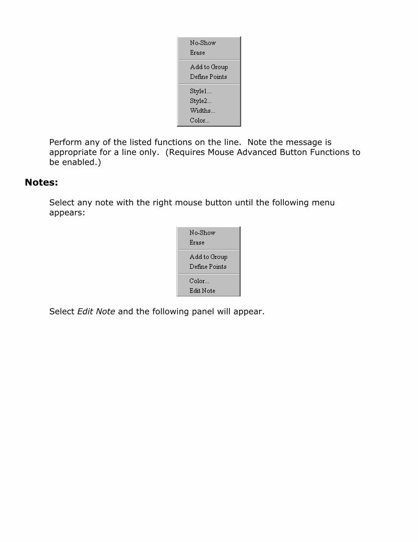
Select any note with the right mouse button until the following menu appears:
Select Edit Note and the following panel will appear.

Evaluate and change any of the existing note parameters and see the change by selecting the button Visualize. If you do not want to keep any of the changes, select Cancel, or keep the changes by selecting OK. (Requires Mouse Advanced Button Functions to be enabled.)

Creating:
CADAM Cursor:
Creates temporary construction points on elements. Also, if you move your cursor over two elements in succession, it provides intersection points of the two elements, normal projections from points, and other points that can be selected to create new geometry.
The example below shows the intersection points of the line and the circle and the end and center points of the line simply by moving the cursor first to the circle then the line. The round target points can be selected for use as if they were permanent points:
Note that Display Tips are also on. Display Tips gives information about elements that typically must be found in FK Analysis
CADAM Cursor, Display Tips and Preselect Highlight are available from the View pull-down menu:

Centerlines:
Centerlines can be quickly added to circles and ellipses by going to FK Line, /CNTR/, and selecting the circle or ellipse. Crossing centerlines are automatically placed. You can key in a different angle or you can Indicate to change the lengths of the crossing centerlines symmetrically.
Cut and Copy between sessions:
You can cut and copy CCD elements between CCD sessions by using the CCD Clipboard. Ensure the CCD Clipboard option is selected in the Edit pull-down menu. Select the desired geometry using the Select menus or icons (Select, Select Window, Select All, or Select Special which gives you all of the FK Group /TRAP/ options). Select Copy from the Edit pull-down menu to copy the elements to the CCD clipboard.
Once copied to the CCD Clipboard, CCD geometry can be pasted to another CCD drawing by using the options Paste or Paste Special. Paste Special

allows you to paste the geometry in a specific location and allows you to decide on what layer geometry should be pasted. Bring up a second CCD session and select Paste or Paste Special from the Edit pull-down menu.
Offset:
Key in multiple offsets with either offsets of differing sizes or as many as 10000 identical offsets. Go to FK Offset. Indicate a side or YN offsets on both sides of the element. Either key in 5 unique offsets separated by commas or key the number of identical offsets followed by the @ sign followed by the size of the offset, e.g., [email protected] will produce 25 identical offsets of 0.1 width.

Grouping:
Create a temporary group:
Depress the left mouse button until the cursor appears. Drag a rectangle and all of the elements inside the rectangle will become a part of the temporary group. All normal group operations such as translate, scale, erase, and many more now become available to this group. (Requires Mouse Advanced Button Functions to be enabled.)
Group operations:
The following group operations are available at any time by depressing the right mouse button in any open space until the following menu appears:
(Requires Mouse Advanced Button Functions to be enabled.)

Panning and Zooming:
Call existing drawing:
Normally when bringing up an existing drawing, it is displayed at window coordinates 0,0 and size = 1. If you would prefer a drawing be brought up at different location and view, simply store that in the Window SET 1 position. To store up to 7 distinct window set positions, first set your window to the position you would like to save, and go to the Window SET toolbar.
Select the set window icon then select any of the 7 window icons. Only the first window set will be used when the drawing is called. Any of the stored postions can be recalled by selecting the appropriate window number icon at any time.
Pan:
Press the center mouse button down until this cursor appears. Continue to hold down the mouse button and pan as you move your mouse. (Requires Mouse Advanced Button Functions to be enabled.)
Pan:
Press the Shift key and depress cursor keys to pan window.
Zoom:
Zoom the window by spinning the wheel on a scroll mouse.
Zoom:
Press the Ctrl key and depress the up and down cursor keys to zoom the window.
Zoom:
Press the first and second buttons of a three button mouse to zoom the window.

Print/Plot:
Plot Current:
You can quickly plot either what is on your current CCD window or create temporary plot data (TPD) to adjust the parameters of the plot. Plot Current differs from Print and Print Wdo-TPD in that it plots to the currently defined plotter (that may or may not be a Windows printer), and you can define a TPD to be used for the current plot only. Print and Print Wdo-TPD always print/plot to a Windows printer.
Select Plot Current in the File pull-down menu. The following panel will appear:
Select Temp Plot Data to bring up the dialog that allows you to change the parameters of the plot including the plot height and width dimensions, scale, load point, etc. When satisfied, YN accept temp plot data and the plot will be automatically submitted. If you select Window TPD, what you see in the current CCD window will be plotted. In all cases, the plot will go to the plotter defined in the Plot Setup (also available in the File pull-down menu).
Print Current Drawing:
You can quickly print either what is on your current CCD window or use any plot data you may have defined. Print is a shortcut method for creating CCD plots. Print will always go to your Windows printer and not to any plotter defined by Plot Setup. Go to the File pull-down menu and select either Print or Print Wdo-TPD. Print will print whatever is in plot data (if defined), and if plot data is not defined, it will print the equivalent of a FK Window /ALL/. Print Wdo-TPD will print what is currently displayed on the CCD window. It automatically creates the TPD (temporary plot data) for you. As with most Windows applications, selecting these options from the File pull-down will bring up the Print properties panels, which will allow you to select a printer and to define properties associated with that printer.

Selecting the equivalent toolbar buttons for Print and Print Wdo-TPD will bypass this panel and will print the drawing to the currently selected printer using the currently defined properties.
General:
Exporting CCD Images to Other Applications:
You can copy selected CCD images to other Windows applications. You have a choice of exporting these images either in color or in monochrome. Select the Edit pull-down menu and you will see the following panel:

Here, you have the choice of selecting the CCD Clipboard or the standard Windows clipboard. The CCD Clipboard allows you to copy actual CCD geometry from a CCD drawing to another CCD drawing. The Windows clipboard is for applications other than CCD, and the image is a bitmap (raster) rather than actual CCD elements. To choose the standard Windows clipboard, make sure that the CCD Clipboard is not selected.
Next choose whether you want the CCD images to be exported in color or in monochrome by either selecting Monochrome or ensuring it is not selected (color). Now you have the choice of either selecting CCD elements using a rectangular trap box (Select), selecting all of the CCD elements displayed in the current window (Select Window), or selecting all of the elements that can be displayed by going to a FK Window /ALL/ (Select All).
Now you can start another application and import the CCD image using the normal Paste command. The following shows a CCD image pasted as both a monochrome and a color image:

FK Box:
Double click with the left mouse button and the following virtual FK box will display:

Select the desired FK button. The WDO FK always appears exactly where you double click.

Mouse Advanced Button Functions:
Go to the Options pull-down menu and select Device Settings...
You will see the following panel:
Ensure that the Advanced Button Functions box is checked. The Press delay (100-1000) parameter defines the length of time you need to hold down the mouse button before the optional function becomes available. The factory setting is 400 milliseconds. Experiment with the setting to see what works best for you.
Object Linking and Embedding:
Files, including Microsoft Word files or even pictures of sail boats can be embedded in a drawing with a link to the application that can modify it. These objects become a part of the actual CCD model.

To embed a file go to the Edit pull-down menu and select Insert New Object. The following panel will appear:

Select Create from File. It will give you the following panel:
Here you may Link to a file or embed a file. If you choose to link a file, when you double click on it in CCD, it will bring up the application that created the file. Any changes you make to the file (if saved) will be reflected in the CCD drawing and will be reflected in the original. If you choose not to link a file, it will be embedded. An embedded file when double clicked in CCD will bring up the application and allow you to change the file, but it will not necessarily change the original file. Selecting Browse from the above panel brings up the directory browser and allows you to choose a file. CCD also allows you to break a link meaning changes to the original file will not be reflected in the CCD drawing.

Overlays, Views and Layers:
When you have a drawing with Overlays, Views and Layers, you can press the right mouse button in any open space, and you will see the following panel:
Moving your cursor over Active View produces the following sub-panel where you can choose to activate a different view if desired:
Moving your cursor over Active Layer produces the following sub-panel where you can choose to activate a new layer if desired:

Moving your cursor over Active Member produces the following sub-panel where you can choose to activate a new overlay member if desired:
Right-clicking on a member of an inactive view, overlay, or layer produces the following option.

Selecting the Activate Context option activates the view, layer and overlay member of that element, allowing you to combine up to 3 possible activation operations into a single operation.
Properties:
Press the right mouse button in any open space until the following panel appears:
Select Properties…, and the following will appear:
This panel allows you to manage many of the properties of a model.

Selecting the Views button gives the following:
Parameters associated with views can be easily evaluated and modified using this panel.

Choosing the Layers button provides a convenient way to manage all of the properties of layers:

Choosing the Overlays button brings up the following panel:
Choosing the Classes button brings up the following panel:
Choosing Style 1 and selecting Change brings up the following panel and allows you to change the Style 1 modal setting. That means all elements selected after the change will reflect the change in Style 1 type.

Choosing Style 2 and selecting Change brings up the following panel and likewise allows you to change the Style 2 modal setting.
Choosing Widths and selecting Change brings up the following panel and allows you to change the modal line width setting.

Choosing Color and selecting Change brings up the following panel and allows you to change the modal default color setting:
Selecting Color Table brings up the following panel and allows you to change the system colors.

Selecting Width Table allows you to define different widths by bringing up the following panel:

Thumbnails (details):
To see a thumbnail of every detail in a drawing, go to FK Detail, /THUMBNAILS/, and all of your details are displayed, as in the following:
Select the desired detail and choose either /USE/ or /DITTO/, and apply the detail as you normally would.

Thumbnails (drawings):
To see thumbnails of drawings when you open them using the File Open… dialog, make sure you check the Update/Create Preview on Save box in the File pull-down menu.
The following shows a thumbnail of a drawing that has been saved.
