cad portfolio - karan shah
TRANSCRIPT
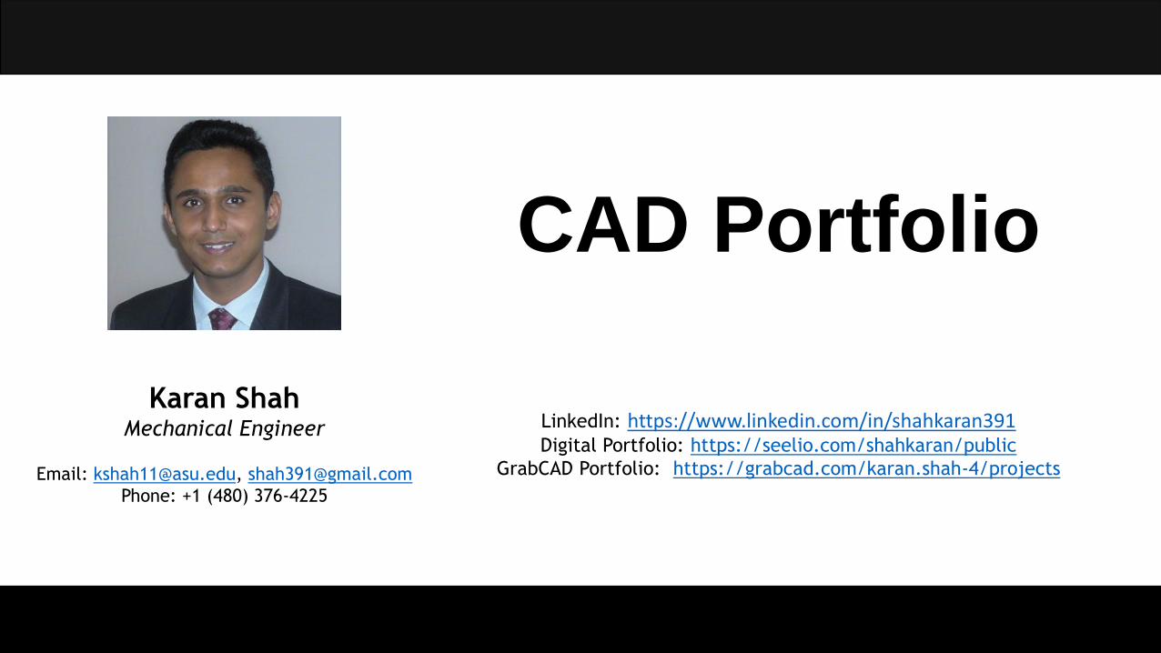
CAD Portfolio
Karan ShahMechanical Engineer
Email: [email protected], [email protected]
Phone: +1 (480) 376-4225
LinkedIn: https://www.linkedin.com/in/shahkaran391Digital Portfolio: https://seelio.com/shahkaran/public
GrabCAD Portfolio: https://grabcad.com/karan.shah-4/projects

INTRODUCTION & ABOUT ME
Introduction:Hello there! My name is Karan Shah and I am a Mechanical Engineer, currently working as a Research Assistant at Arizona State University. ThisCAD Portfolio is created to supplement my resume that allows me to showcase the CAD Skills I have gained and developed over the course of myeducational and professional career. I have recently graduated with a Master’s degree in Mechanical Engineering from Arizona State University.Now, I stand on the threshold of my professional career holding a Masters degree looking forward to building a challenging and successful careeras Product Design Engineer/ Product Development Engineer/ Mechanical Engineer that can take me to the frontiers in the fascinating field ofmechanical engineering.
About Me:Product design is my passion and CAD modeling is my strength. I am proficient with multiple CAD packages as described in my resume and I caneasily make a transition from one package to another based on the requirement. I consider myself to be a creative individual capable ofvisualizing a conceptual idea and converting the same into a perceptible 3D model. Not to forget, I have self-learned surface modeling usingSolidworks only to satiate my love for designing cars.
Online Portfolios:I have showcased my CAD models via GrabCAD online 3D viewer and engineering skills through a digital portfolio that also supplements myresume and extensively describes each project that I have completed throughout my engineering education. These can be reached by followingthe links provided below.
Digital Portfolio: https://seelio.com/shahkaran/public GrabCAD Portfolio: https://grabcad.com/karan.shah-4/projects
2

TABLE OF CONTENTS
3
S.NO TITLE SOFTWARE PAGE NO
1 Chevrolet Camaro – Surface Modeling Solidworks 4
2 Lamborghini Aventador – Surface Modeling Solidworks 8
3 Aston Martin DB9 – Surface Modeling Solidworks 12
4 Bugatti Veyron – Surface Modeling Solidworks 15
5 Lapping Machine PTC Creo Elements/Direct Modeling 17
6 Design of a Home Appliance – Lawnmower PTC Creo Elements/Direct Modeling 20
7 Design of a Creature PTC Creo Elements/Direct Modeling 25
8 V6 Engine Solidworks 28
9 Design of a Book & Gadget Holder PTC Creo Elements/Direct Modeling 31
10 Design for Autodesk: Radio Controlled Helicopter Autodesk Fusion 360 34
11 Design for Autodesk: Forklift Autodesk Fusion 360 35
12 Autonomous Surveillance Vehicle Autodesk Inventor 36
13 Shot Buddy – Basketball Returning Machine CATIA V5 39
14 Orange Picking Device Autodesk Inventor 42
15 Miniature Steam Engine Autodesk Inventor 44
16 Furniture Hardware Solidworks 45
17 Sketches Free-Hand Drawing 47

CHEVROLET CAMARO – SURFACE MODELING
Overview:The body panels of Chevrolet Camaro have been modeled using SolidWorks based on the following blueprint sketches. The body panels havebeen developed using surface modelling tools like compound splines, projected curves, surface loft, boundary and filled surfaces, surface trimand indent tool. This project is completed based on my personal interest of 3D modelling of cars.
Top View
Front View Side View Rear View4

5Rendered Images

6Rendered Images

7Rendered Images

LAMBORGHINI AVENTADOR – SURFACE MODELING
Overview:The body panels of Lamborghini Aventador have been modeled using SolidWorks based on the following blueprint sketches. The body panelshave been developed using surface modelling tools like compound splines, projected curves, surface loft, boundary and filled surfaces,surface trim and indent tool. This project is completed based on my personal interest of 3D modelling of cars.
Top View
Front View Side View Rear View8

Rendered Images 9

Rendered Images 10
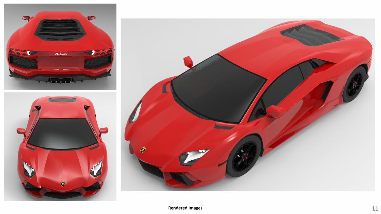
Rendered Images 11

ASTON MARTIN DB9 – SURFACE MODELING
Overview:The body panels of Aston Martin DB9 have been modeled using SolidWorks based on the following blueprint sketches. The body panels havebeen developed using surface modelling tools like compound splines, projected curves, surface loft, boundary and filled surfaces, surfacetrim and indent tool. This project is completed based on my personal interest of 3D modelling of cars.
Top View
Front View Side View Rear View12

13Rendered Images
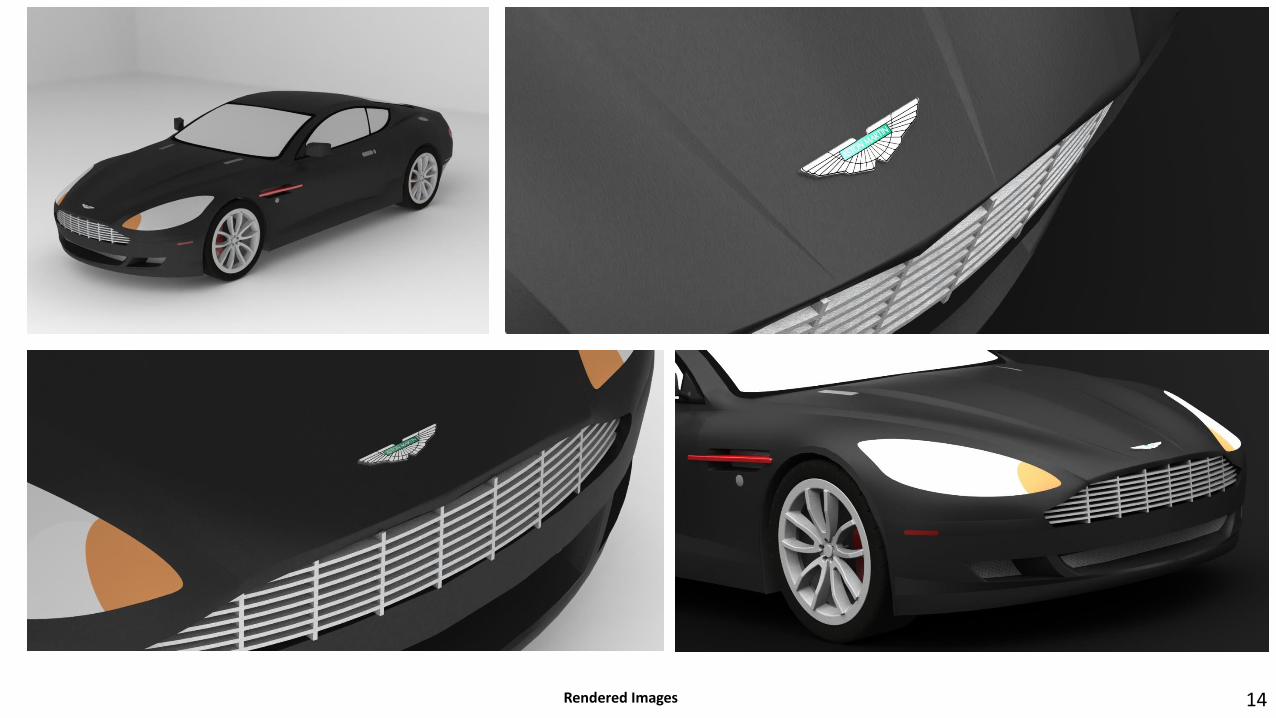
14Rendered Images

BUGATTI VEYRON – SURFACE MODELLING
Overview:The body panels of the Bugatti Veyron have been modelled using SolidWorks based on the following blueprint sketches. The body panels havebeen developed using surface modelling tools like compound splines, projected curves, surface loft, boundary and filled surfaces, surface trimand indent tool. This project is completed based on my personal interest of 3D modelling of cars.
Top View
Front View Side View Rear View
15

Rendered Images 16

LAPPING MACHINE
17
Overview:Lapping Machine is used to carry out the lapping process to obtain surface finish by material removal when pressed against each other in the presence of an abrasive. I have completed this model of the Lapping Machine as a part of my work as a Research Assistant at Arizona State University. 3D Model is generated based on rough 2D drawings obtained from hand measurement.
Rendered Images

18Rendered Images

19Rendered Images

DESIGN OF A HOME APPLIANCE - LAWNMOWER
Overview:The aim of this team project was to design a home appliance that consists of at least one primary rotating component. The following images attached demonstrates the CAD model of the Lawnmower and the components and their respective sub-assemblies like the battery system, engine system and the fuel system together forming the power system that I have designed. The other sub-assemblies like the cutting deck, chassis, hydraulic system and lifting mechanism have also been displayed but they have been designed by my other team members.
20Rendered Images

List of Images:
Top Row (Left to Right)1. Isometric Front View of the
Chassis2. Isometric Rear View of the
Chassis3. Lifting Mechanism
Middle Row (Left to Right)1. Top View of the Cutter Deck2. Bottom View of the Cutter
Deck3. Lifting Mechanism and Cutter
Deck Assembly
Bottom Row (Left to Right)1. Isometric View of the Power
System2. Isometric View of the
Hydraulic System3. Power System and Hydraulic
System Assembly
21

List of Images:
Top Row (Left to Right)1. Battery2. Battery Holder3. Battery Assembly
Middle Row (Left to Right)1. Radiator Grill2. Radiator Fan3. Flywheel
Bottom Row (Left to Right)1. Piston2. Crankshaft3. Crankshaft Assembly
22

List of Images:
Top Row (Left to Right)1. Lubricating Tray2. Engine Fins3. Mounting Plate
Middle Row (Left to Right)1. Cylinder Head2. Engine Body3. Air Filter
Bottom Row (Left to Right)1. Intake Hose-Manifold2. Air Intake System3. Engine Assembly
23

List of Images:
Top Row (Left to Right)1. Exhaust Manifold2. Exhaust Canister3. Exhaust Canister Mounting4. Fuel Tank
Middle Row (Left to Right)1. Fuel Tank Mounting Bracket2. Fuel Pump3. Fuel Pump Assembly4. Fuel Filter 5. Fuel Filter Assembly
Bottom Row (Left to Right)1. Carburetor and Butterfly Valve2. Fuel Line3. Fuel Pump Outlet4. Fuel System Assembly
24

Overview:The objective of this project was to design a creature capable of three worldly interactions. I choose a Pegasus as the creature which iscapable of flapping its wings, walking and nodding its head as the three worldly interactions. A final design was to be designed representingthe skin of the creature and the assembly of the three selected mechanisms for the interactions with fasteners and standard parts like gears,motors and linkages. The final design should be easily placed inside a box of 0.5 x 0.5 x 0.5 meters.
Final Design with Skin Final Design Assembly of Mechanisms
DESIGN OF A CREATURE
25

Flapping Wings – Concept 1 Head Nodding – Concept 1 Walking – Concept 1
Flapping Wings – Concept 2
Head Nodding – Concept 2 Walking – Concept 2 26

Wing Flapping – Final Design Head Nodding – Final Design Final Design – Rear Isometric View
Walking – Final Design Complete Assembly – Final Design Final Design – Left View
27

V6 ENGINE – DESIGN & ASSEMBLY OF COMPONENTS
Overview:This project consists of design of individual components of a V6 Engine followed by the assembly of each components into a final engineassembly. All the components have been designed and the final assembly have been carried out using SolidWorks.
Air Filter Belt Wheel Belt Wheel Air Turbo
Camshaft CrankshaftCylinder Head Engine Block 28

Crankshaft Assembly Oil Pan
Camshaft AssemblyIntake Manifold
Piston Assembly
Exhaust Manifold
Rocker Arm
Engine Valves
29

Final Assembly of the Engine Internal View of the Assembled Engine
30
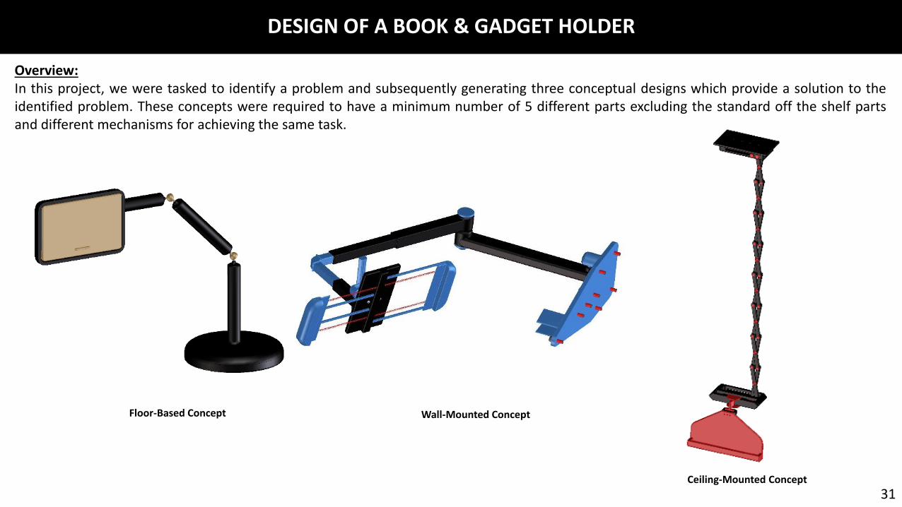
DESIGN OF A BOOK & GADGET HOLDER
Overview:In this project, we were tasked to identify a problem and subsequently generating three conceptual designs which provide a solution to theidentified problem. These concepts were required to have a minimum number of 5 different parts excluding the standard off the shelf partsand different mechanisms for achieving the same task.
Floor-Based Concept Wall-Mounted Concept
Ceiling-Mounted Concept
31

Device in a different orientation due to ball & socket joint Object holder in object holding position
Scissor linkages in fully extended positionThe sliding link, rotary link and the hinge joint
oriented as per user's convenience. Object Holder without any orientation32

Fully Modelled Final DesignCompact position of the device as it is fixed to the self-
contained fixture.Telescopic Linkages retracted allowing user to extend
a desired distance for comfort.
Sliding Joint, Rotary joint & Hinge joint are depicted that allow orientation.
Image showing the device in a completely different orientation and angular position of the object holder.
Figure 5: Object holder depicting the spring loaded sliding brackets to hold gadgets & book holder with roller wheels.
33
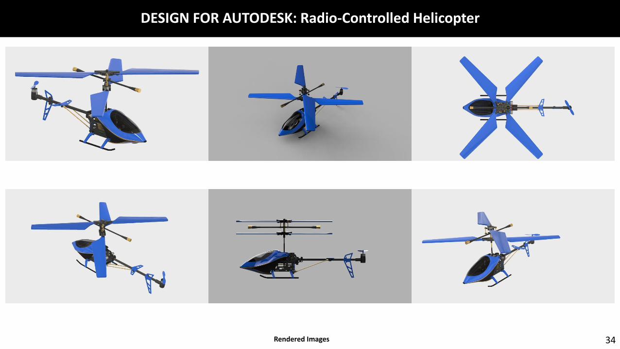
DESIGN FOR AUTODESK: Radio-Controlled Helicopter
34Rendered Images
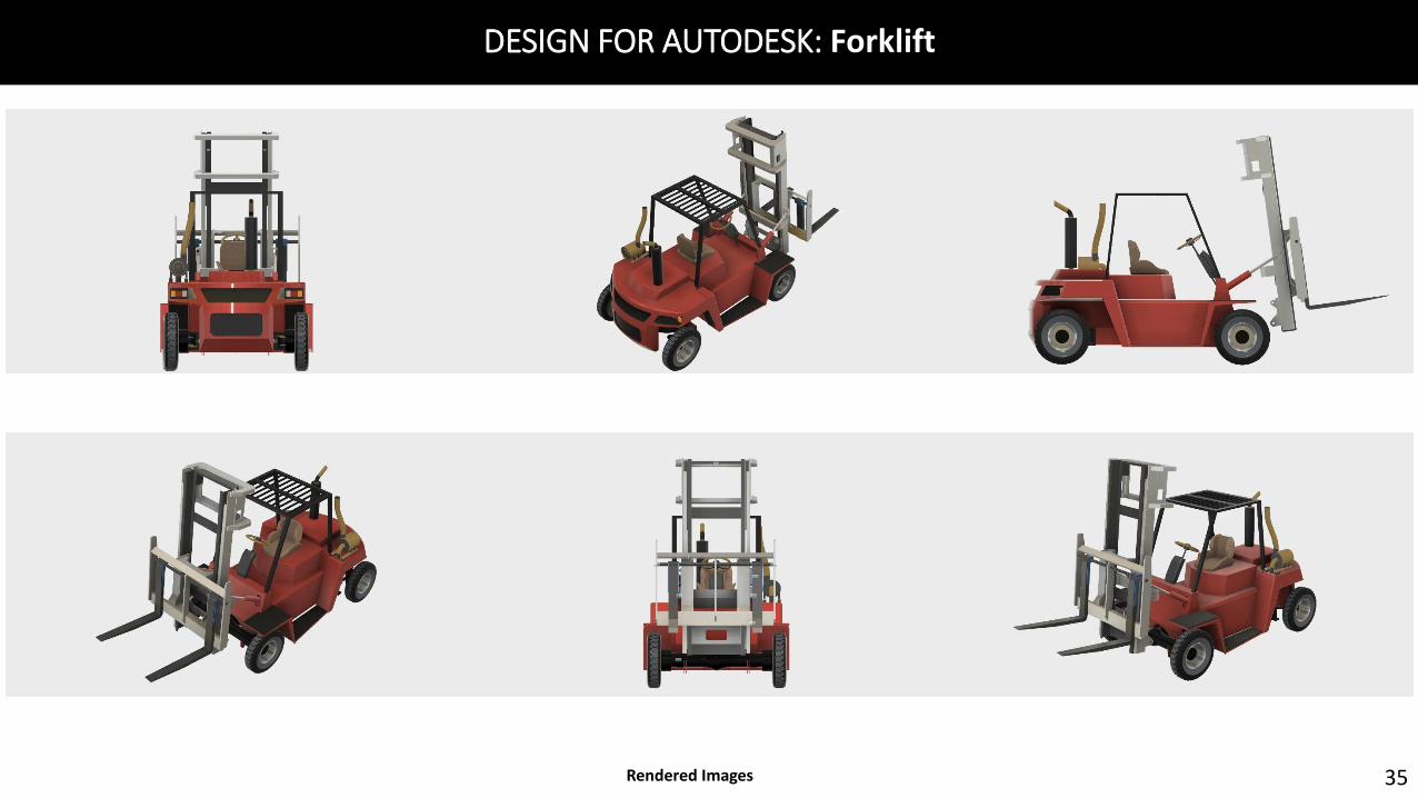
DESIGN FOR AUTODESK: Forklift
35Rendered Images
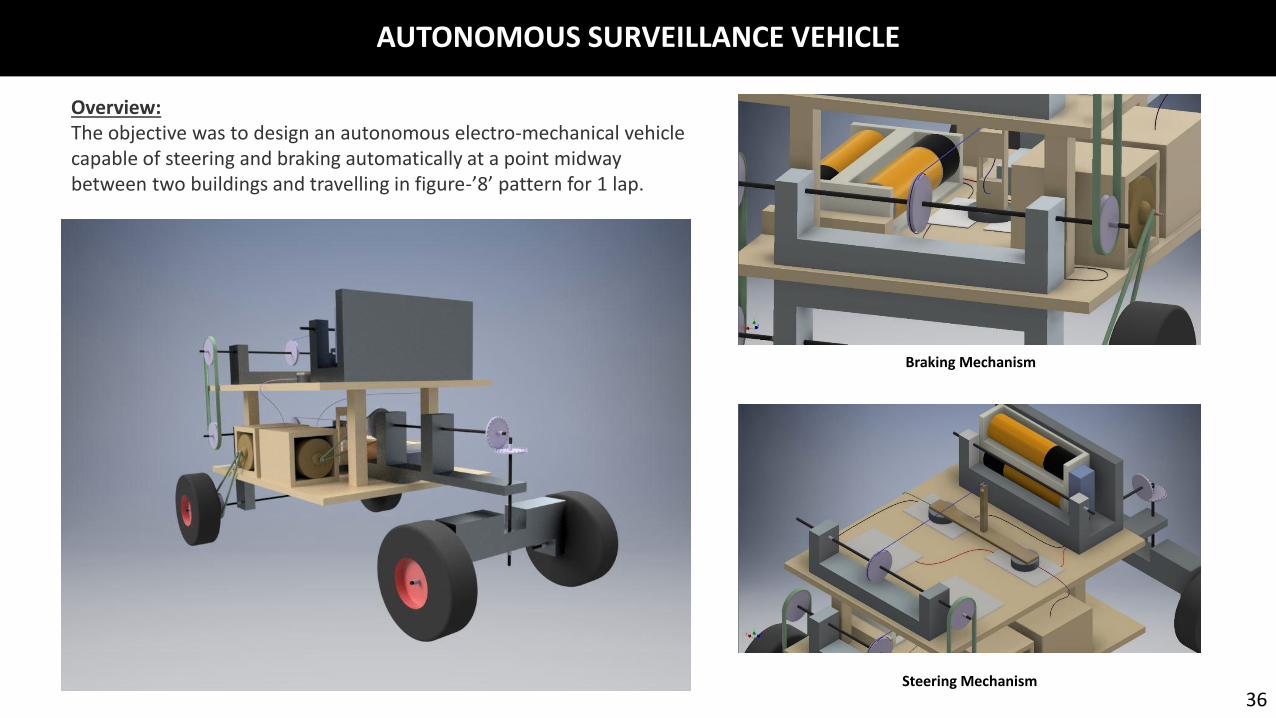
AUTONOMOUS SURVEILLANCE VEHICLE
36Steering Mechanism
Braking Mechanism
Overview:The objective was to design an autonomous electro-mechanical vehicle capable of steering and braking automatically at a point midway between two buildings and travelling in figure-’8’ pattern for 1 lap.
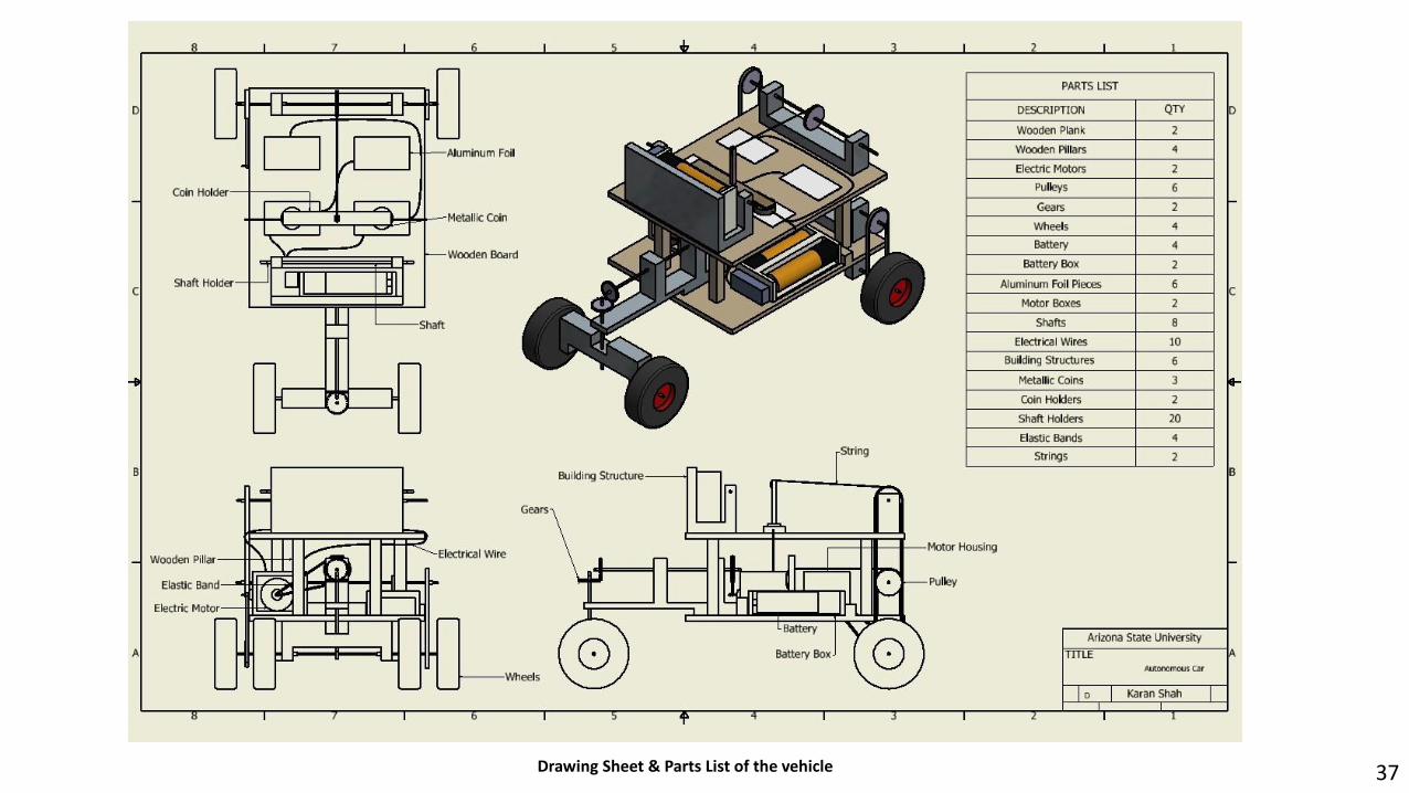
Drawing Sheet & Parts List of the vehicle 37

Transmission Assembly Front View
38Final Fabricated vehicle

SHOT BUDDY – Basketball Returning Device
Isometric View of the Model 39Bill of Materials
Overview:The objective was to design a basketball returning machine capable of returning the basketball to the shooter within a radius of 24 feet from the basketball hoop.

Concept Sketches 40
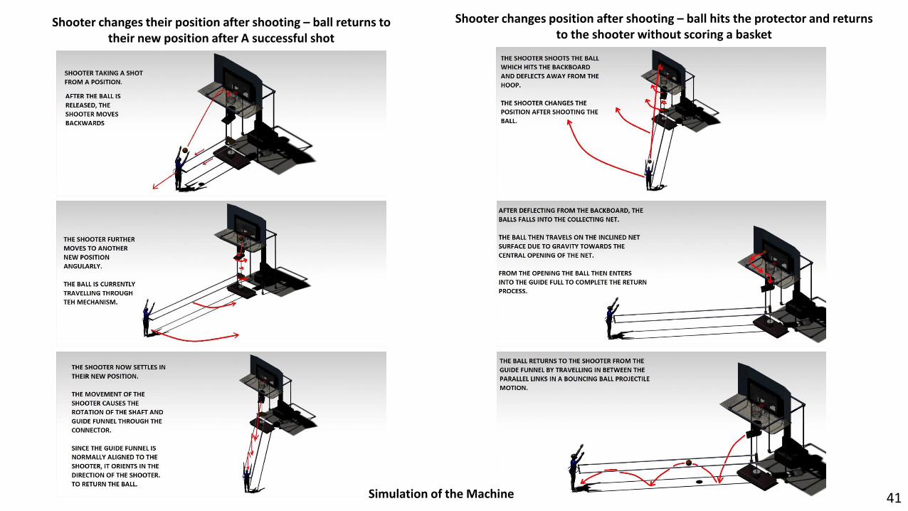
Shooter changes their position after shooting – ball returns to their new position after A successful shot
Shooter changes position after shooting – ball hits the protector and returns to the shooter without scoring a basket
Simulation of the Machine 41
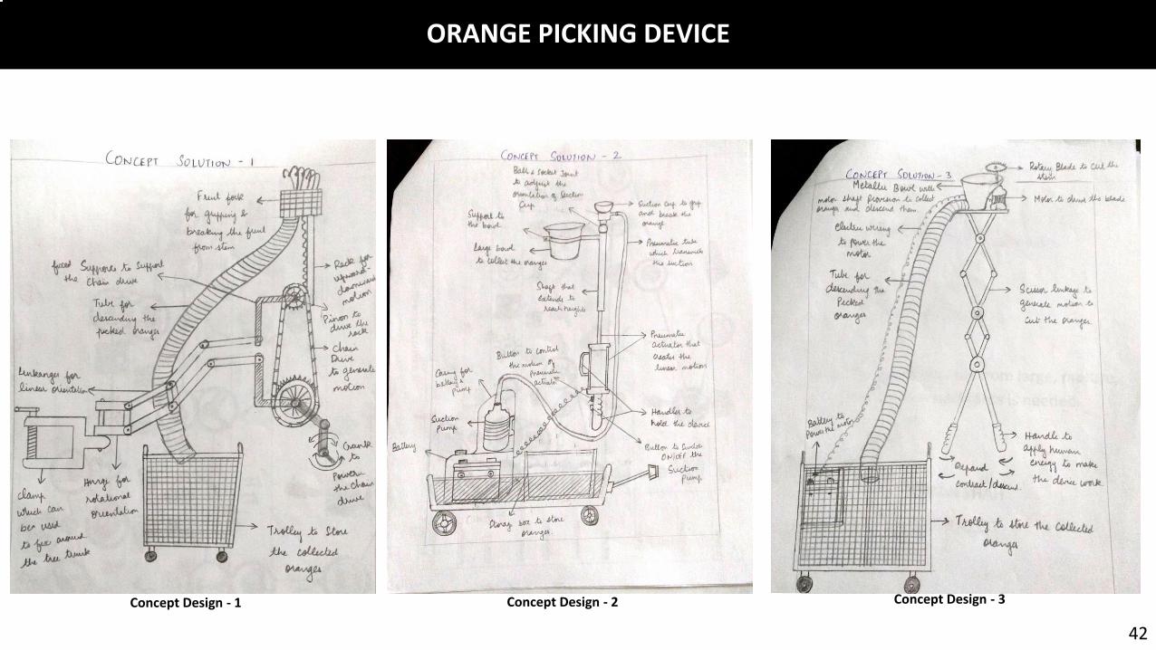
ORANGE PICKING DEVICE
42
Concept Design - 1 Concept Design - 2 Concept Design - 3
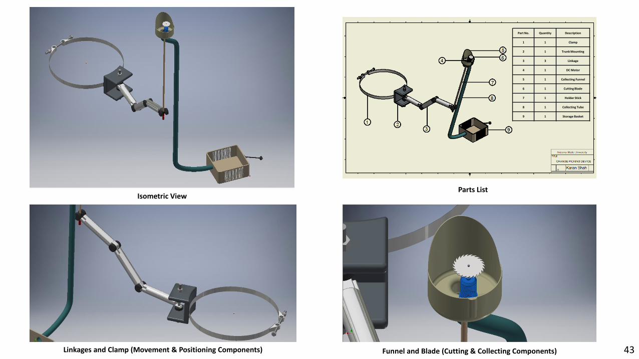
Part No. Quantity Description
1 1 Clamp
2 1 Trunk Mounting
3 3 Linkage
4 1 DC Motor
5 1 Collecting Funnel
6 1 Cutting Blade
7 1 Holder Stick
8 1 Collecting Tube
9 1 Storage Basket
Isometric View
Linkages and Clamp (Movement & Positioning Components)
Parts List
Funnel and Blade (Cutting & Collecting Components) 43

MINIATURE STEAM ENGINE
Overview:Designed a miniature version of a steam engine assembly. Every part was designed based on available blueprints and CAD drawings obtainedfrom the internet.
44Rendered Images

FURNITURE HARDWARE
45
Overview:I designed a few models for cabinet pulls and curtain brackets while working as a Chief Design Officer at Harshit Enterprises, my family owned business of furniture hardware dealership.
Curtain Brackets

Cabinet Pulls
Furniture Hardware Showcase
46

SKETCHES
47

48