cad-0208 series communication appliance...cad-0208 series user’s manual 5 chapter 2 getting...
TRANSCRIPT

CAD-0208 Series Communication Appliance
User′s Manual Revision: 1.1
CE This certificate of conformity of CAD-0208 series with actual required safety standards in accordance with 89/366 ECC-EMC Directive and LVD 73/23 ECC
UL This product meets all safety requirements per UL60950 standard.

CAD-0208 Series User’s Manual
1
Table of Contents Chapter 1 Introduction...................................................... 2
1.1 About This Manual. ............................................................. 2
1.2 Manual Organization ........................................................... 2
1.3 Technical Support Information.............................................. 2
1.4 Board Layout……… .............................................................. 3
1.5 System Block Diagram ........................................................ 3
1.6 Product Specification........................................................... 4
Chapter 2 Getting Started.............................................. 5
2.1 Included Hardware ............................................................. 5
2.2 Before You Begin….............................................................. 5
2.3 Hardware Configuration Setting ............................................ 6
2.4 The Chassis………. ............................................................... 9
2.5 Open the Chassis… ............................................................. 9
2.6 Hard drive Install….. ......................................................... 10
2.7 Thermal Pad Install........................................................... 11
2.8 Remove and Install DIMM .................................................. 12
2.9 Remove and Install CF card ............................................... 14
2.10 Wall-Mount Installation ..................................................... 15
2.11 Use a Client Computer ...................................................... 16
Chapter 3 BIOS Setting................................................. 17

CAD-0208 Series User’s Manual
2
Chapter 1 Introduction
1.1 About This Manual
This manual contains all required information for setting up and using the CAD-0208 series.
CAD-0208 provides the essential platform for delivering optimal performance and functionality in the entry communications applia nce market segmen t. This manu al shou ld familiarize you with CAD-0208 operations and functi ons.CAD-0208-3422 series prov ide up to 4 on-board Ethernet ports to serve communication applications like Fi rewall, requiring 4 E thernet p orts t o co nnect external network (internet), demilitarized zone and internal network.
CAD-0208 series overview: INTEL ATOM D510 1.66GHz Memory: One DDR2 SODIMM slot and up to 2G Four Gigabit Ethernet interfaces with two Bypass segments Independent management console(RS232) One min-PCI -E socket for mini-PCI-E / USB device connectivity. One 2.5” SATA Hard disk
1.2 Manual Organization
This manual describes how to configure y our CAD- 0208 system to m eet various operating requirements. It is divided into three chapters, with each chapter addressing the basic concept and operation of this system.
Chapter 1: Introduction. This section describes how this document is organized. It includes brief guidelines and overview to help find necessary information.
Chapter 2: Hardware Configuration Setting and Installation. This chapter demonstrated the hardware assembly procedure, including detailed information. It shows the definitions and locations of Jumpers and Connectors that can be used to configure the system.
Chapter 3: Operation Information. This section provides illustrations and information on the system architecture and how to optimize its performance.
Any updates to this manual, would be posted on the web site:
http://www.portwell.com/products/index.html
1.3 Technical Support Information
Users may find helpful tips or rela ted information on Portwell's web site: http://www.portwell.com A direct contact to Portwell's technical person is also available.

CAD-0208 Series User’s Manual
3
1.4 Board Layout
Figure 1-1 Board Layout of CAD-0208 M/B
1.5 System Block Diagram
Figure 1-2 CAD-0208 Basic Block Diagram
Pineview-M
ICH8M
PCI-E GbE-082583V
PCI-E GbE-1 82583V
PCI-E GbE-282583V
PCI-E GbE-382583V
RJ45 RJ45 RJ45 RJ45
SOD
IMM
D
DR
2 667 Onboard VGAPin header
Bypass 0
BIOS/Firmware
Dual USB Ports
RJ45 System Console
2xSATA slot
CF Socket
Mini PCIe slot
PCI-E x1
Bypass 1

CAD-0208 Series User’s Manual
4
1.6 Product Specification
Feature Detailed Description
1 CPU ․Onboard ATOM N450 1.66GHz processor
2 CPU Board ․CAPB-0208VD with Intel ATOM D510+ ICH8M ․Board dimension: 170x140mm
3 System Memory
․1 x 200-pin SO-DIMM socket ․Support DDR2 667 max. up to 2GB, non-ECC
4 VGA Interface ․1 x Internal VGA pin header (2 x 5-pin) ․A semi-cutting hole for st andard D-Sub 15-pin VGA connector on chassis.
PCI-E Ethernet ․Max. four PCI-E GbE ports base on Intel 82583V
5 S torage Device ․1 x SATA 2.5” Hard disk ․1 x CF
6 Exp ansion slots ․1 x mini PCIe
7 Chassis ․Form factor: 1U desktop chassis ․To accommodate: M/B, HDD bracket for 2.5” ․Dimension: 300x140x40mm
8 Front Panel
Ethernet interfaces: Four RJ45 Ethernet connectors. RS232 interface: RS232 port with RJ45 connector for system console USB interface: dual-USB connectors Hardware Reset Button LED:
-- System LED: Power and Data access. -- Ethernet LED
9 Rear Panel AC power inlet A semi-cutting hole for 15-pin VGA connector A semi-cutting hole for wireless antenna
10 PSU 60W, 15V power adapter
11 Dimension 300x150x40mm
12 Environmental requirements
Storage temp.: -20°C to 70°C Operating temp.: 0°C to 40°C. Humidity: 10 to 90% RH non-condensing
CAD-0208 Series User’s Manual
5
Chapter 2 Getting Started This section describes how the hardware installation and system settings should be done.
2.1 Incl uded Hardware
The following hardware is included in package:
CAD-0208 Communication Appliance System Board One null serial port cable AC-DC Adapter SATA cable Hard disk ground cable Chassis foot pad Hard disk assembly kits
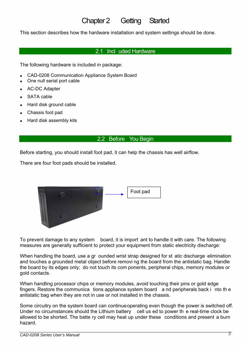
2.2 Before You Begin
Before starting, you should install foot pad, it can help the chassis has well airflow.
There are four foot pads should be installed.
To prevent damage to any system board, it is import ant to handle it with care. The following measures are generally sufficient to protect your equipment from static electricity discharge:
When handling the board, use a gr ounded wrist strap designed for st atic discharge elimination and touches a grounded metal object before removi ng the board from the antistatic bag. Handle the board by its edges only; do not touch its com ponents, peripheral chips, memory modules or gold contacts.
When handling processor chips or memory modules, avoid touching their pins or gold edge fingers. Restore the communica tions appliance system board a nd peripherals back i nto th e antistatic bag when they are not in use or not installed in the chassis.
Some circuitry on the system board can continue operating even though the power is switched off. Under no circumstances should the Lithium battery cell us ed to power th e real-time clock be allowed to be shorted. The batte ry cell may heat up under these conditions and present a burn hazard.
Foot pad

CAD-0208 Series User’s Manual
6
WARNING!
1. "CAUTION: DANGER OF EXPLOSION IF BATTERY IS INCORRECTLY REPLACED. REPLACE ONLY WITH SAME OR EQUIVALENT TYPE RECOMMENDED BY THE MANUFACTURER. DISCARD USED BATTERIES ACCORDING TO THE MANUFACTURER’S INSTRUCTIONS"
2. This guide is for technically qualified personnel who have experience installing and configuring system boards. Disconnect the system board power supply from its power source before you connect/disconnect cables or install/remove any system board components. Failure to do this can result in personnel injury or equipment damage.
3. Avoid short-circuiting the lithium battery; this can cause it to superheat and cause burns if touched.
4. Do not operate the processor without a thermal solution. Damage to the processor can occur in seconds.
5. Do not block air vents. Minimum 1/2-inch clearance required.
2.3 Hardware Configuration Setting
2.3.1 CAD-0208 System
2.3.2 CAD-0208 System Board Jumper
In general, jumpers o n CAD-0208 system board are used to select options for certain features. Some of the jumpers a re conf igurable for system enhancement. The others are for testing purpos e only and should not be al tered. To select any option, cover the jumper cap over (Short) or remove (NC) it from the jumper pins according to the following instructions. Here NC stands for “Not Connected”.
Location of Jumpers

CAD-0208 Series User’s Manual
7
JP1: CMOS Clear
JP1 Function 1-2 Short Normal Operation * 2-3 Short Clear CMOS Contents
JP2: WDT
JP2 Function 1-2 Short WDT Enable * 1-2 Open WDT Disable
JP4, JP5 :By-pass and normal mode
JP4, JP5 Function 1-3 , 2-4 Short Power on default at Normal mode , mode
selection is S/W programmable* 3-5 , 2-4 Short Power on default at Bypass mode , mode
selection is S/W programmable 4-6 Short Always at normal mode.
JP6~JP21: Bypass and Open Mode Selection
JP6~JP21 Function JP6~21(1-2) short
Byp ass Mode *

CAD-0208 Series User’s Manual
8
JP6~21(1-2) Open
Open Mode
Connector Function Remark D2 HDD LED +Power LED D3 By-pass LED
D4~D7 LAN LED J1 8-bit GPIO connector J2 VGA connector
J5 PS2 Pin Header J6 Mini PCI Express Card Socket J7 CF socket J8 DDR2 DIMM Slot J9 +5V & +12V Power Connector (Only Output)
J10,J11 SATA connector J12 USB connector
J13~J16 RJ45 connector J17 Console Port J18 DC Power Jack (15V) J19 Fan Connector SW1 Reset To Default SW2 System Reset Button
J1: 8-bit GPIO connector define
Pin Signal Name Pin Signal Name 1 GPIO 2 GPIO 3 GPIO 4 GPIO 5 GPIO 6 GPIO 7 GPIO 8 GPIO 9 Grou nd 10 +5V
J2: VGA connector define
Pin Signal Name Pin Signal Name 1 RED 2 DDCCLK 3 GREEN 4 Ground 5 BLUE 6 DDCDATA 7 HSYNC 8 Ground 9 VSYNC 10 N/C
J9: +5V & +12V Power Connector (Only Output)
Pin Signal Name 1 VDD_ 12V 2 GND 3 GND 4 VDD_ 5V
CAD-0208 Series User’s Manual
9
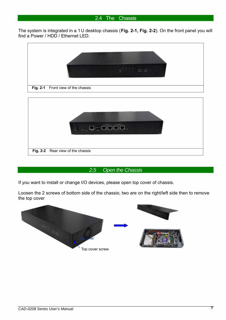
2.4 The Chassis
The system is integrated in a 1U desktop chassis (Fig. 2-1, Fig. 2-2). On the front panel you will find a Power / HDD / Ethernet LED.
Fig. 2-1 Front view of the chassis
Fig. 2-2 Rear view of the chassis
2.5 Open the Chassis
If you want to install or change I/O devices, please open top cover of chassis. Loosen the 2 screws of bottom side of the chassis; two are on the right/left side then to remove the top cover
Top cover screw
CAD-0208 Series User’s Manual
10
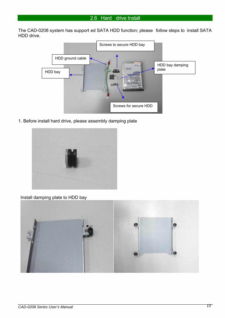
2.6 Hard drive Install
The CAD-0208 system has support ed SATA HDD function; please follow steps to install SATA HDD drive.
1. Before install hard drive, please assembly damping plate
Install damping plate to HDD bay
HDD bay
HDD ground cable
HDD bay damping plate
Screws to secure HDD bay
Screws for secure HDD

CAD-0208 Series User’s Manual
11
2. Use 4 screws to secure the drive into HDD bay and also secure HDD ground cable
3. Fix HDD bay and connect SATA cable to hard drive and board connector
4. Connect HDD ground cable to M/B
2.7 Thermal Pad Install
The CAD-0208 system was used thermal pad to help chipsets cooling.
Please follow steps to install thermal pad.
1. To clean the bottom side of chassis before install thermal pad
2. The thermal pad is high performance material; please does not touch pad directly by hand
CAD-0208 Series User’s Manual
12
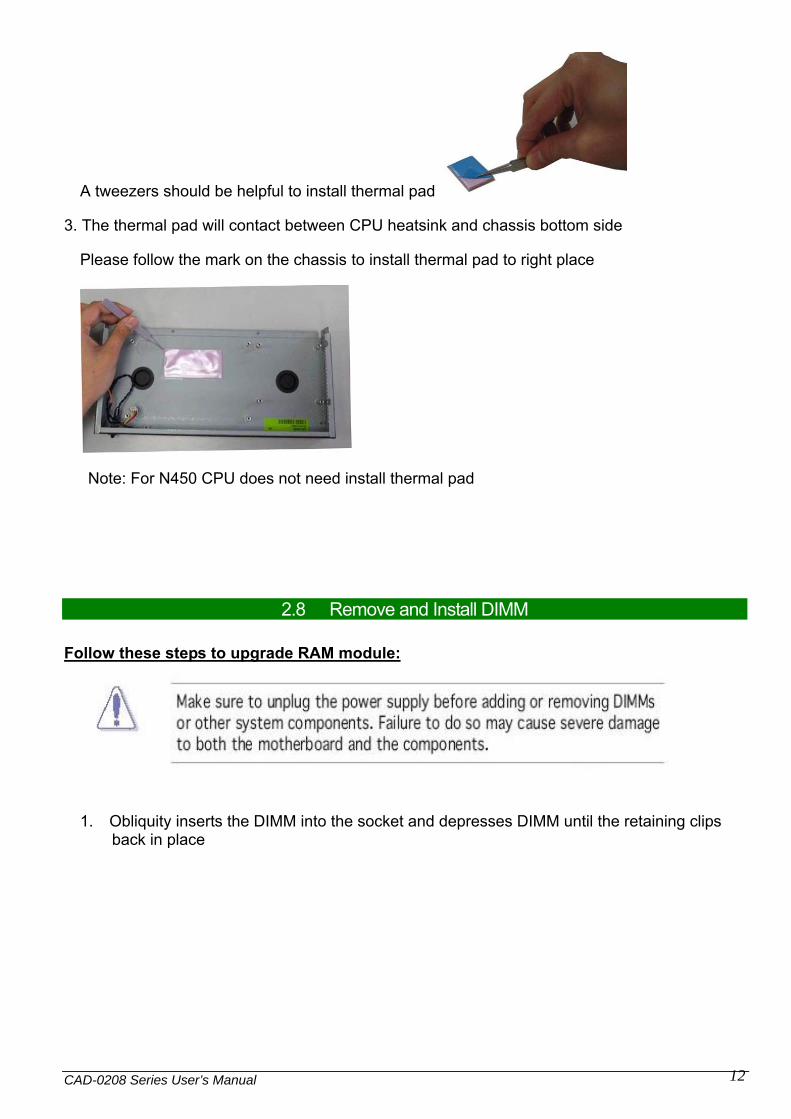
A tweezers should be helpful to install thermal pad
3. The thermal pad will contact between CPU heatsink and chassis bottom side
Please follow the mark on the chassis to install thermal pad to right place
Note: For N450 CPU does not need install thermal pad
2.8 Remove and Install DIMM
Follow these steps to upgrade RAM module:
1. Obliquity inserts the DIMM into the socket and depresses DIMM until the retaining clips back in place

CAD-0208 Series User’s Manual
13
Follow these steps to remove a DIMM: 1. Pull the retaining clips of DIMM socket simultaneously to unlock the DIMM
2. Remove the DIMM from the socket

CAD-0208 Series User’s Manual
14
2.9 Remove and Install CF card
Insert the Compact Flash Card (Fig. 2-3) into the CF interface (Fig. 2-4).
Fig. 2-3 Compact Flash Card Fig. 2-4 Insert Compact Flash Card into
the CF interface
The completed installation of Compact Flash Card is shown as Fig. 2-4
Fig. 2-4 Completion of Compact Flash Card connection

CAD-0208 Series User’s Manual
15
2.10 Wall-Mount Installation
You can mount the CAD-0208 on a wall using the two mounting brackets on the bottom of the appliance. We recommend that you use two round or pan head screws. 1. Install two screws 200 mm horizontally apart on a wall or other vertical surface. The screws should protrude from the wall so that you can fit the appliance between the head of the screw and the wall.
If you install the screws in drywall, use hollow wall anchors to ensure that the unit does not pull away from the wall due to prolonged strain from the cable and power connectors. 2. Remove the CAD-0208 and accessories from the shipping container. 3. Mount the CAD-0208 on the wall as shown below.
4. Do not mount the CAD-0208 on the wall as shown below.
200mm
CAD-0208 Series User’s Manual
16
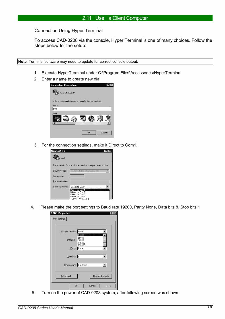
2.11 Use a Client Computer
Connection Using Hyper Terminal
To access CAD-0208 via the console, Hyper Terminal is one of many choices. Follow the steps below for the setup:
Note: Terminal software may need to update for correct console output.
1. Execute HyperTerminal under C:\Program Files\Accessories\HyperTerminal 2. Enter a name to create new dial
3. For the connection settings, make it Direct to Com1.
4. Please make the port settings to Baud rate 19200, Parity None, Data bits 8, Stop bits 1
5. Turn on the power of CAD-0208 system, after following screen was shown:

CAD-0208 Series User’s Manual
17
This is the end of this section. If the term inal did not port correctly, pleas e check the previous steps.
Chapter 3 BIOS Setting Power on the system, press the <Del> to run BIOS setup (remote mode is <Tab>). After you press the <Delete> key, the main BIOS setup menu displays. You can access the other setup screens from the main BIOS setup menu, such as the Chipset and Power menus. The BIOS setup/utility uses a key-based navigation system called hot keys. Most of the BIOS setup utility hot keys can be used at any time during the setup navigation process. These keys include <F1>, <F10>, <Enter>, <ESC>, <Arrow> keys, and so on.
Control Keys Key Function
↑↓Up /Down The Up and Down <Arrow> keys allow you to select a setup item or sub-screen.
Left/Right
The Left and Right <Arrow> keys allow you to select a setup screen. For example: Main screen, Advanced screen, Chipset screen, and so on.
+ - Plus/ Minus
The Plus and Minus <Arrow> keys allow you to change the field value of a particular setup item. For example: Date and Time.

CAD-0208 Series User’s Manual
18
Tab The <Tab> key allows you to select setup fields.

CAD-0208 Series User’s Manual
19
Main Menu
When you first enter the Setup Utility, you will enter the Main setup screen. You can always return to the Main setup screen by selecting the Main tab. There are two Main Setup options. They are described in this section. In console mode: Press “TAB” key can into BISO setup man menu Press “B” key can popup device boot menu Press “L” key can boot from network
System Date / Time

CAD-0208 Series User’s Manual
20
Use this option to change the system time and date. Highlight System Time or System Date using the <Arrow> keys. Enter new values through the keyboard. Press the <Tab> key or the <Arrow> keys to move between fields. The date must be entered in MM/DD/YY format. The time is entered in HH:MM:SS format.
Advanced BIOS Setup Select the Advanced tab from the setup screen to enter the Advanced BIOS Setup screen. You can select any of the items in the left frame of the screen, such as SuperIO Configuration, to go to the sub menu for that item. You can display an Advanced BIOS Setup option by highlighting it using the <Arrow> keys. All Advanced BIOS Setup options are described in this section. The Advanced BIOS Setup screen is shown below. The sub menus are described on the following pages.
.
IDE Configuration Setup From the IDE Configuration screen, press <Enter> to access the sub menu. Use the up and down <Arrow> keys to select an item. The settings are described on the following pages.
SUPER IO CONFIGURATION SuperIO Configuration

CAD-0208 Series User’s Manual
21
You can use this screen to select options for the Super I/O settings. Use the up and down <Arrow> keys to select an item. Use the <Plus> and <Minus> keys to change the value of the selected option. The settings are described on the following pages. The screen is shown below.
REMOTE ACCESS CONFIGURATION Remote Access Configuration You can use this screen to select options for the Remote Access Configuration. Use the up and down <Arrow> keys to select an item. Use the <Plus> and <Minus> keys to change the value of the selected option. The settings are described on the following pages. The screen is shown below.
Remote Access You can disable or enable the BIOS remote access feature here.
Serial Port Number Select the serial port you want to use for console redirection. You can set the value for this option to either COM1 or COM2.
CAD-0208 Series User’s Manual
22
Serial Port Mode Select the baud rate you want the serial port to use for console redirection.
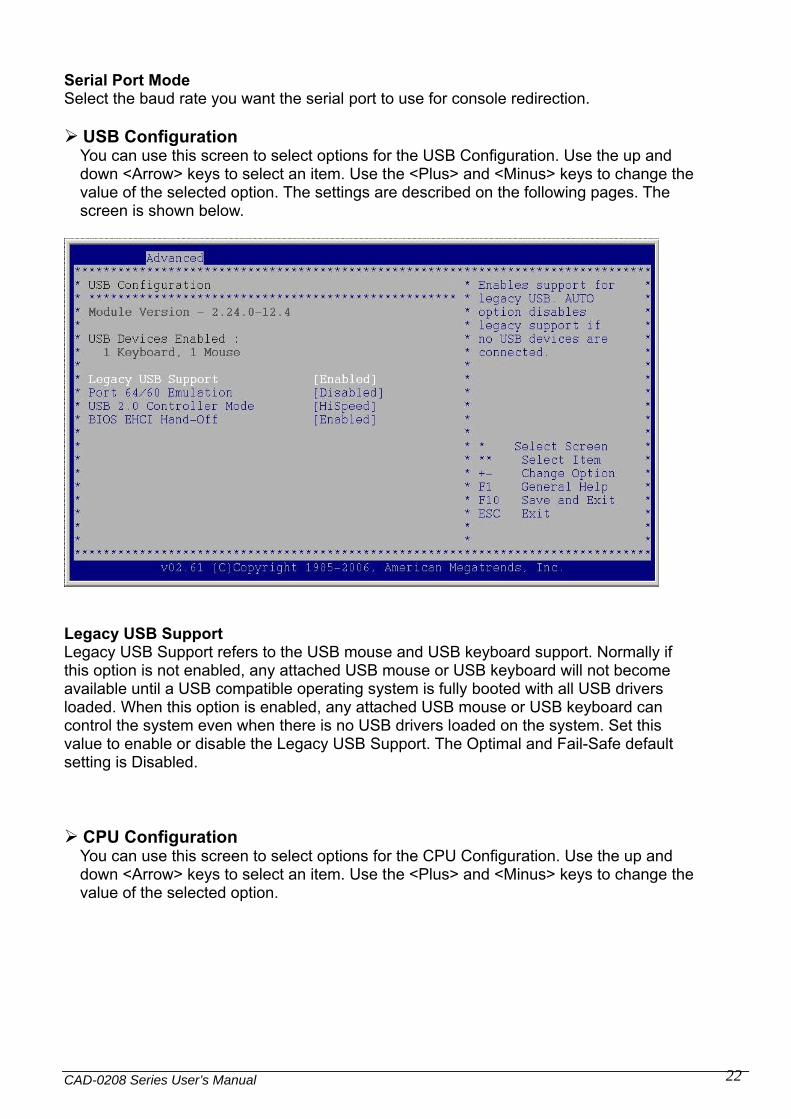
USB Configuration You can use this screen to select options for the USB Configuration. Use the up and down <Arrow> keys to select an item. Use the <Plus> and <Minus> keys to change the value of the selected option. The settings are described on the following pages. The screen is shown below.
Legacy USB Support Legacy USB Support refers to the USB mouse and USB keyboard support. Normally if this option is not enabled, any attached USB mouse or USB keyboard will not become available until a USB compatible operating system is fully booted with all USB drivers loaded. When this option is enabled, any attached USB mouse or USB keyboard can control the system even when there is no USB drivers loaded on the system. Set this value to enable or disable the Legacy USB Support. The Optimal and Fail-Safe default setting is Disabled.
CPU Configuration You can use this screen to select options for the CPU Configuration. Use the up and down <Arrow> keys to select an item. Use the <Plus> and <Minus> keys to change the value of the selected option.

CAD-0208 Series User’s Manual
23
Note: The CPU Configuration setup screen varies depending on the installed processor.
Boot Settings Select the Boot tab from the setup screen to enter the Boot BIOS Setup screen.
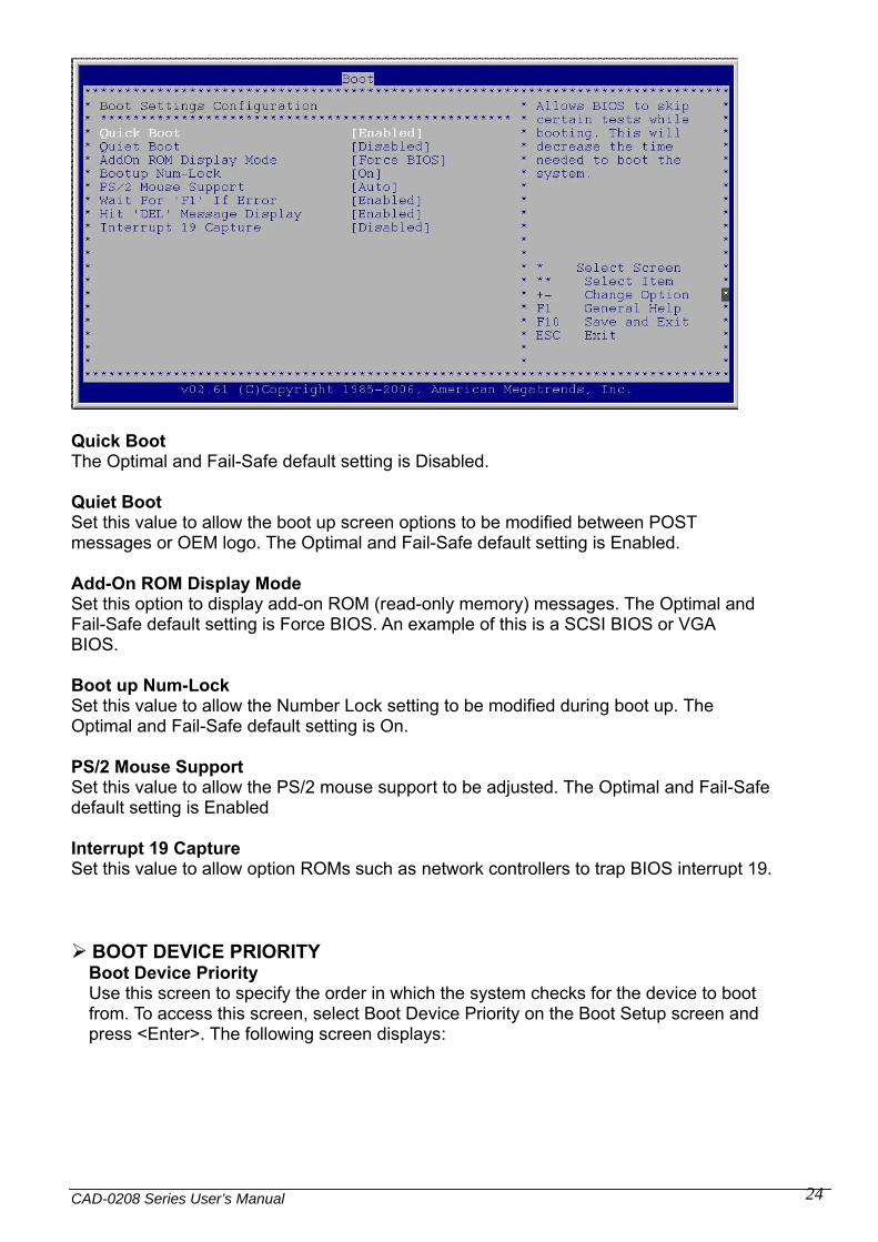
BOOT SETTINGS CONFIGURATION SCREEN Boot Settings Configuration Use this screen to select options for the Boot Settings Configuration. Use the up and down <Arrow> keys to select an item. Use the <Plus> and <Minus> keys to change the value of the selected option. The settings are described on the following pages. The screen is shown below.
CAD-0208 Series User’s Manual
24
Quick Boot The Optimal and Fail-Safe default setting is Disabled. Quiet Boot Set this value to allow the boot up screen options to be modified between POST messages or OEM logo. The Optimal and Fail-Safe default setting is Enabled. Add-On ROM Display Mode Set this option to display add-on ROM (read-only memory) messages. The Optimal and Fail-Safe default setting is Force BIOS. An example of this is a SCSI BIOS or VGA BIOS. Boot up Num-Lock Set this value to allow the Number Lock setting to be modified during boot up. The Optimal and Fail-Safe default setting is On. PS/2 Mouse Support Set this value to allow the PS/2 mouse support to be adjusted. The Optimal and Fail-Safe default setting is Enabled Interrupt 19 Capture Set this value to allow option ROMs such as network controllers to trap BIOS interrupt 19.
BOOT DEVICE PRIORITY Boot Device Priority Use this screen to specify the order in which the system checks for the device to boot from. To access this screen, select Boot Device Priority on the Boot Setup screen and press <Enter>. The following screen displays:

CAD-0208 Series User’s Manual
25
Exit Menu Select the Exit tab from the setup screen to enter the Exit BIOS Setup screen. You can display an Exit BIOS Setup option by highlighting it using the <Arrow> keys. All Exit BIOS Setup options are described in this section. The Exit BIOS Setup screen is shown below.
Saving Changes and Exit When you have completed the system configuration changes, select this option to leave Setup and reboot the computer so the new system configuration parameters can take effect. Select Exit Saving Changes from the Exit menu and press <Enter>. Discarding Changes and Exit Select this option to quit Setup without making any permanent changes to the system configuration. Select Exit Discarding Changes from the Exit menu and press <Enter>.

CAD-0208 Series User’s Manual
26
Discard Changes Select Discard Changes from the Exit menu and press <Enter>. Load Optimal Defaults Automatically sets all Setup options to a complete set of default settings when you select this option. Select Load Optimal Defaults from the Exit menu and press <Enter>. Load Fail-Safe Defaults Automatically sets all Setup options to a complete set of default settings when you select this option. The Fail-Safe settings are designed for maximum system stability, but not maximum performance. Select the Fail-Safe Setup options if your computer is experiencing system configuration problems. Select Load Fail-Safe Defaults from the Exit menu and press <Enter>.