cable tray system - semco maritimehr-fb60-300-150r- 300 375 390 1.56. heavy duty 90° flat bend =...
TRANSCRIPT
Cable Tray System
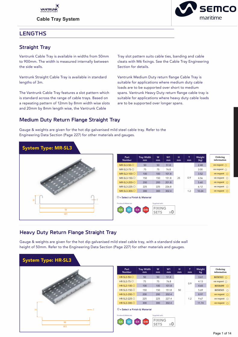
Medium Duty Return Flange Straight Tray
Gauge & weights are given for the hot dip galvanised mild steel cable tray. Refer to the Engineering Data Section (Page 227) for other materials and gauges.
W
W1
H T
PartNumber
Tray Widthmm
Wmm
W1mm
Hmm
Tmm
Weight (kg)
MR-SL3-50- 50 50 51.8
25 0.9
2.48
MR-SL3-75- 75 75 76.8 3.00
MR-SL3-100- 100 100 101.8 3.52
MR-SL3-150- 150 150 151.8 4.56
MR-SL3-200- 200 200 201.8 5.60
MR-SL3-225- 225 225 226.8 6.12
MR-SL3-300- 300 300 302.4 1.2 10.24
= Select a Finish & Material
Straight TrayVantrunk Cable Tray is available in widths from 50mm to 900mm. The width is measured internally between the side walls.
Vantrunk Straight Cable Tray is available in standard lengths of 3m.
The Vantrunk Cable Tray features a slot pattern which is standard across the range of cable trays. Based on a repeating pattern of 12mm by 8mm width wise slots and 20mm by 8mm length wise, the Vantrunk Cable
Tray slot pattern suits cable ties, banding and cable cleats with M6 fixings. See the Cable Tray Engineering Section for details.
Vantrunk Medium Duty return flange Cable Tray is suitable for applications where medium duty cable loads are to be supported over short to medium spans. Vantrunk Heavy Duty return flange cable tray is suitable for applications where heavy duty cable loads are to be supported over longer spans.
Heavy Duty Return Flange Straight TrayGauge & weights are given for the hot dip galvanised mild steel cable tray, with a standard side wall height of 50mm. Refer to the Engineering Data Section (Page 227) for other materials and gauges.
= Select a Finish & Material
W
W1
H T
PartNumber
Tray Widthmm
Wmm
W1mm
Hmm
Tmm
Weight kg
HR-SL3-50- 50 50 51.8
50
0.9
3.61
HR-SL3-75- 75 75 76.8 4.13
HR-SL3-100- 100 100 101.8 4.65
HR-SL3-150- 150 150 151.8 5.69
HR-SL3-200- 200 200 202.4
1.2
8.97
HR-SL3-225- 225 225 227.4 9.67
HR-SL3-300- 300 300 302.4 11.74
System Type: MR-SL3
System Type: HR-SL3
Finishes & Materials:
x0FIXINGSETS
Supplied with:
GA SS GX GW
Finishes & Materials:
x0FIXINGSETS
Supplied with:
GA SS GX GW
LENGTHS
Ordering information
on request
on request
on request
on request
on request
on request
on request
Ordering information
8058503on request
80584998058505on request
on request
on request
Page 1 of 14

Cable Tray System
Heavy Duty Return Flange 30° Flat Bend
Part Number Width W mm
Tmm
Rmm
Xmm
Ymm
Weight(kg)
HR-FB30-50-75R- 50
0.9 75
61 63 0.12
HR-FB30-75-75R- 75 86 75 0.16
HR-FB30-100-75R- 100 111 88 0.19
HR-FB30-150-75R- 150 161 113 0.27
HR-FB30-200-150R- 200
1.2 150
221 175 0.61
HR-FB30-225-150R- 225 246 188 0.67
HR-FB30-300-150R- 300 321 225 0.92
Heavy Duty 45° Flat Bend
X
W
T
Y
R
H
Part Number WidthW mm
Tmm
Rmm
Xmm
Ymm
Weightkg
HR-FB45-50-75R- 50
0.9 75
72 89 0.16
HR-FB45-75-75R- 75 97 107 0.2
HR-FB45-100-75R- 100 122 124 0.25
HR-FB45-150-75R- 150 172 160 0.35
HR-FB45-200-150R- 200
1.2 150
224 248 0.83
HR-FB45-225-150R- 225 269 266 0.94
HR-FB45-300-150R- 300 344 319 1.29
= Select a Finish & Material
Gauge & weights are given for the hot dip galvanised mild steel cable tray, with a nominal standard sidewall height of 50mm. Refer to the Engineering Data Section (Page 227) for other materials and gauges.
Finishes & Materials:
SEE ENGINEERINGDATA FOR NUMBEROF FIXINGS
Supplied with:
GA SS GX
Not Required:
SEE ENGINEERINGDATA FOR NUMBEROF FIXINGS
Supplied with: Not Required:
GW
= Select a Finish & Material
Gauge & weights are given for the hot dip galvanised mild steel cable tray, with a nominal standard sidewall height of 50mm. Refer to the Engineering Data Section (Page 227) for other materials and gauges.
GA SS
Finishes & Materials:
GX GW
Fitting Type: HR-FB30
Fitting Type: HR-FB45
W
T
X
Y
R
H
FLAT BENDS
Ordering information
on request8067255
on requeston requeston requeston requeston request
Ordering information
on requeston requeston requeston requeston requeston requeston request
Page 2 of 14

Cable Tray System
SEE ENGINEERINGDATA FOR NUMBEROF FIXINGS
Supplied with: Not Required:
SEE ENGINEERINGDATA FOR NUMBEROF FIXINGS
Supplied with: Not Required:
Heavy Duty 60° Flat Bend
Part Number WidthW mm
Tmm
Rmm
Xmm
Ymm
Weight(kg)
HR-FB60-50-75R- 50
0.9 75
88 109 0.18
HR-FB60-75-75R- 75 113 130 0.24
HR-FB60-100-75R- 100 138 152 0.29
HR-FB60-150-75R- 150 188 195 0.42
HR-FB60-200-150R- 200
1.2 150
275 304 1.02
HR-FB60-225-150R- 225 300 325 1.13
HR-FB60-300-150R- 300 375 390 1.56
Heavy Duty 90° Flat Bend
= Select a Finish & Material
Gauge & weights are given for the hot dip galvanised mild steel cable tray, with a nominal standard sidewall height of 50mm. Refer to the Engineering Data Section (Page 227) for other materials and gauges.
Part Number WidthW mm
Tmm
Rmm
Xmm
Ymm
Weightkg
HR-FB90-50-75R- 50
0.9 75
125 125 0.25
HR-FB90-75-75R- 75 150 150 0.32
HR-FB90-100-75R- 100 175 175 0.41
HR-FB90-150-75R- 150 225 225 0.59
HR-FB90-200-150R- 200
1.2 150
350 350 1.5
HR-FB90-225-150R- 225 375 375 1.69
HR-FB90-300-150R- 300 450 450 2.32
Finishes & Materials:
GA SS GX GW
= Select a Finish & Material
Gauge & weights are given for the hot dip galvanised mild steel cable tray, with a nominal standard sidewall height of 50mm. Refer to the Engineering Data Section (Page 227) for other materials and gauges.
GA SS
Finishes & Materials:
GX GW
W
T
X
Y
R
W
T
X
Y
R
Fitting Type: HR-FB60
Fitting Type: HR-FB90
H
H
Ordering information
on requeston requeston requeston requeston requeston requeston request
Ordering information
on request8068948
on requeston requeston requeston requeston request
Page 3 of 14
Cable Tray System
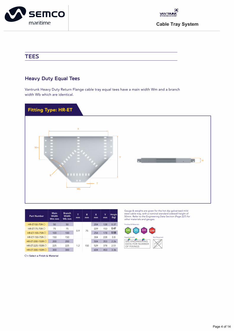
Heavy Duty Equal Tees
Vantrunk Heavy Duty Return Flange cable tray equal tees have a main width Wm and a branch width Wb which are identical.
X
Wb
T
Wm
Y
R
H
Part NumberMain Width
Wm mm
Branch Width
Wb mm
Tmm
Rmm
Xmm
Ymm
Weight(kg)
HR-ET-50-75R- 50 50
0.9 75
204 128 0.37
HR-ET-75-75R- 75 75 229 153
HR-ET-100-75R- 100 100 254 178
0.47GA SS GX
0.58
HR-ET-150-75R- 150 150 304 228 0.8
HR-ET-200-150R- 200 200
1.2 150
504 353 2.26
HR-ET-225-150R- 225 225 529 378 2.51
HR-ET-300-150R- 300 300 604 453 3.36
= Select a Finish & Material
Fitting Type: HR-ET
Gauge & weights are given for the hot dip galvanised mild steel cable tray, with a nominal standard sidewall height of 50mm. Refer to the Engineering Data Section (Page 227) for other materials and gauges.
Finishes & Materials:
GW
SEE ENGINEERINGDATA FOR NUMBEROF FIXINGS
Supplied with: Not Required:
TEES
0.47GA SS GX
0.58
Page 4 of 14

Cable Tray System
HR-UT-200-50-150R-
200
50
1.2 150
354 353 1.62
HR-UT-200-75-150R- 75 379 353 1.72
HR-UT-200-100-150R- 100 404 353 1.83
HR-UT-200-150-150R- 200 454 353 2.04
HR-UT-200-225-150R- 225 529 353 2.36
HR-UT-200-300-150R- 300 604 353 2.69
HR-UT-225-50-150R-
225
50
1.2 150
354 378 1.71
HR-UT-225-75-150R- 75 379 378 1.83
HR-UT-225-100-150R- 100 404 378 1.94
HR-UT-225-150-150R- 150 454 378 2.17
HR-UT-225-200-150R- 200 504 378 2.4
HR-UT-225-300-150R- 300 604 378 2.86
HR-UT-300-50-150R-
300
50
1.2 150
354 453 2.02
HR-UT-300-75-150R- 75 379 453 2.15
HR-UT-300-100-150R- 100 404 453 2.29
HR-UT-300-150-150R- 150 454 453 2.56
HR-UT-300-200-150R- 200 504 453 2.82
HR-UT-300-225-150R- 225 529 453 2.95
Heavy Duty Unequal Tees
= Select a Finish & Material
Gauge & weights are given for the hot dip galvanised mild steel cable tray, with a nominal standard sidewall height of 50mm. Refer to the Engineering Data Section (Page 227) for other materials and gauges.
GA SS
Finishes & Materials:
GX GW
X
Wb
T
Wm
R
Y
H
Fitting Type: HR-UT
Part NumberMain Width
Wm mm
Branch Width
Wb mm
Tmm
Rmm
Xmm
Ymm
Weight(kg)
HR-UT-50-75-75R-
50
75
0.9 75
229 128 0.42
HR-UT-50-100-75R- 100 254 128 0.45
HR-UT-50-150-75R- 150 304 128 0.54
HR-UT-50-200-150R- 200
1.2 150
504 203 1.41
HR-UT-50-225-150R- 225 529 203 1.49
HR-UT-50-300-150R- 300 604 203 1.7
HR-UT-75-50-75R-
75
50
0.9 75
204 153 0.43
HR-UT-75-100-75R- 100 254 153 0.51
HR-UT-75-150-75R- 150 304 153 0.6
HR-UT-75-200-150R- 200
1.2 150
504 228 1.55
HR-UT-75-225-150R- 225 529 228 1.64
HR-UT-75-300-150R- 300 604 228 1.87
HR-UT-100-50-75R-
100
50
0.9 75
204 178 0.48
HR-UT-100-75-75R- 75 229 178 0.52
HR-UT-100-150-75R- 150 304 178 0.66
HR-UT-100-200-150R- 200
1.2 150
504 253 1.69
HR-UT-100-225-150- 225 529 253 1.78
HR-UT-100-300-150R- 300 604 253 2.03
HR-UT-150-50-75R-
150
50
0.9 75
204 228 0.58
HR-UT-150-75-75R- 75 229 228 0.63
HR-UT-150-100-75R- 100 254 228 0.68
HR-UT-150-200-150R- 200
1.2 150
504 303 1.98
HR-UT-150-225-150R- 225 529 303 2.08
HR-UT-150-300-150R- 300 604 303 2.35
SEE ENGINEERINGDATA FOR NUMBEROF FIXINGS
Supplied with: Not Required:
Page 5 of 14
Cable Tray System
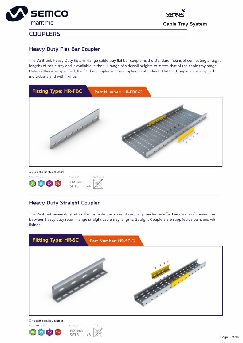
Heavy Duty Flat Bar Coupler
The Vantrunk Heavy Duty Return Flange cable tray flat bar coupler is the standard means of connecting straight lengths of cable tray and is available in the full range of sidewall heights to match that of the cable tray range. Unless otherwise specified, the flat bar coupler will be supplied as standard. Flat Bar Couplers are supplied individually and with fixings.
GA SS
= Select a Finish & Material
Finishes & Materials:
GX GW FIXINGSETS x4
Supplied with: Not Required:
Part Number: HR-FBC-Fitting Type: HR-FBC
Heavy Duty Straight Coupler
The Vantrunk heavy duty return flange cable tray straight coupler provides an effective means of connection between heavy duty return flange straight cable tray lengths. Straight Couplers are supplied as pairs and with fixings.
= Select a Finish & Material
Finishes & Materials:
GA SS GX GW FIXINGSETS x8
Supplied with: Not Required:
Part Number: HR-SC-Fitting Type: HR-SC
COUPLERS
Page 6 of 14

Cable Tray System
Heavy Duty Flat Horizontal Adjustable Coupler
The Vantrunk Heavy Duty Return Flange cable tray horizontal adjustable coupler allows horizontal adjustment between adjacent lengths of cable tray and is available in the full range of sidewall heights to match that of the Heavy Duty cable tray. Horizontal Adjustable Couplers are supplied individually and with fixings.
= Select a Finish & Material Finishes & Materials:
GA SS GX GW FIXINGSETS x4
Supplied with: Not Required:
Part Number: HR-FHAC-Fitting Type: HR-FHAC
Heavy Duty Flat Vertical Adjustable Coupler
The Vantrunk Heavy Duty Return Flange cable tray vertical adjustable coupler is the standard means of allowing vertical adjustment between adjacent lengths of cable tray and is available in the full range of sidewall heights to match that of the Heavy Duty cable tray.
The vertical adjustable coupler features easi-bend slots which allow the couplers to be adjusted on site to create combined horizontal & vertical offset connections, tray connections onto the side of a cable tray run to form tee connections, or connections directly to a wall or floor. Vertical Adjustable Couplers are supplied individually and with fixings.
= Select a Finish & Material Finishes & Materials:
GA SS GX GW FIXINGSETS x4
Supplied with: Not Required:
Part Number: HR-FVAC-Fitting Type: HR-FVAC
122Ordering information
8058568
Page 7 of 14
Cable Tray System
Cable Tray System
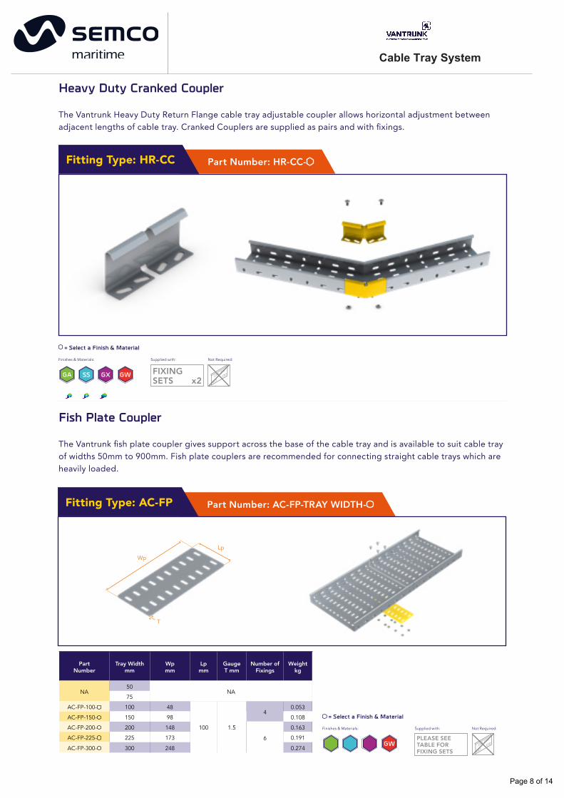
Heavy Duty Cranked Coupler
The Vantrunk Heavy Duty Return Flange cable tray adjustable coupler allows horizontal adjustment between adjacent lengths of cable tray. Cranked Couplers are supplied as pairs and with fixings.
GA SS
= Select a Finish & Material
Finishes & Materials:
GX GW FIXINGSETS x2
Supplied with: Not Required:
Part Number: HR-CC-Fitting Type: HR-CC
Fish Plate Coupler
The Vantrunk fish plate coupler gives support across the base of the cable tray and is available to suit cable tray of widths 50mm to 900mm. Fish plate couplers are recommended for connecting straight cable trays which are heavily loaded.
PartNumber
Tray Widthmm
Wpmm
Lpmm
GaugeT mm
Number of Fixings
Weightkg
NA50
NA75
AC-FP-100- 100 484
0.053
AC-FP-150- 150 98 0.108
AC-FP-200- 200 148 100 1.5
6
0.163
AC-FP-225- 225 173
AC-FP-300- 300 248
0.191GA SS GX
0.274
Part Number: AC-FP-TRAY WIDTH-Fitting Type: AC-FP
= Select a Finish & Material
Finishes & Materials:
GWPLEASE SEE TABLE FOR FIXING SETS
Supplied with: Not Required:
Wp
Lp
T
Page 8 of 14
Cable Tray System
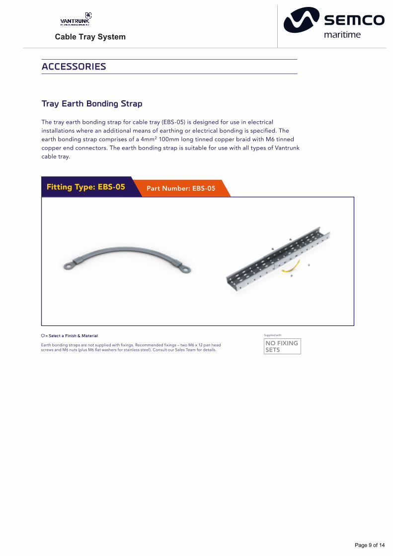
Tray Earth Bonding Strap
The tray earth bonding strap for cable tray (EBS-05) is designed for use in electrical installations where an additional means of earthing or electrical bonding is specified. The earth bonding strap comprises of a 4mm2 100mm long tinned copper braid with M6 tinned copper end connectors. The earth bonding strap is suitable for use with all types of Vantrunk cable tray.
Earth bonding straps are not supplied with fixings. Recommended fixings – two M6 x 12 pan head screws and M6 nuts (plus M6 flat washers for stainless steel). Consult our Sales Team for details.
= Select a Finish & Material
NO FIXINGSETS
Supplied with:
Part Number: EBS-05Fitting Type: EBS-05
ACCESSORIES
Page 9 of 14
Cable Tray System
= Select a Finish & Material
Finishes & Materials:
W1 + 80 GA SS GX GW
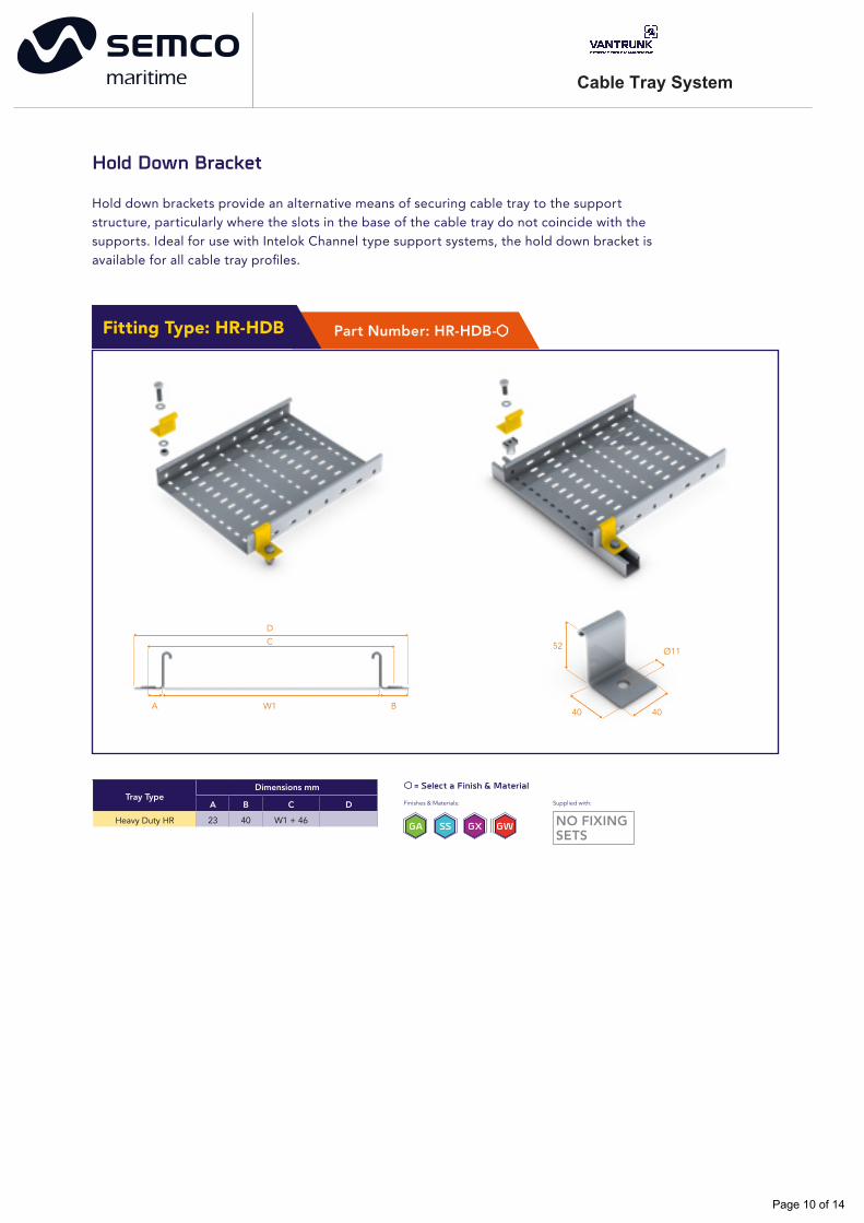
Hold Down Bracket
Hold down brackets provide an alternative means of securing cable tray to the support structure, particularly where the slots in the base of the cable tray do not coincide with the supports. Ideal for use with Intelok Channel type support systems, the hold down bracket is available for all cable tray profiles.
NO FIXINGSETS
Supplied with:
Part Number: HR-HDB-Fitting Type: HR-HDB
52
40
Ø11
40
DC
W1A B
Tray TypeA B C D
Heavy Duty HR 23 40 W1 + 46
Dimensions mm
Page 10 of 14

Cable Tray System
Ordering information 8068955 Ordering information
8068956
Straight Tray Divider
Straight tray dividers are available for cable segregation and separation purposes along the length of the cable run. Straight tray dividers are available to suit all cable tray sections and are available in 3m lengths as standard.
Fitting Type: DF
= Select a Finish & Material
Finishes & Materials:
GA SS GX GW NO FIXINGSETS
Supplied with:
Information shown is for hot dip galvanised carbon steel in the standard gauge; other gauges are available, please consult our Sales Team for details.
Straight tray dividers are not supplied with fixings (3 fixings required per straight divider).
Recommended fixings – M6 x 12 pan head screw and M6 nut (plus M6 flat washer for stainless steel). Consult our Sales Team for details.
Subject to order requirements, straight tray dividers may be supplied in 1.5m lengths to suit delivery & shipping needs.
H
L
T
F
Part NumberDimensions mm
L H F T
HR-DF- -1.2 3000 47 20 1.2
Tray Fitting Divider
Tray fitting dividers are availablefor cable segregation and separation purposes on fittings. The tray fitting divider is supplied as a 600mm straight length and is notched to allow for forming around flat bends, tees, crosses & reducers. Tray fitting dividers are available to suit all cable tray sections.
Fitting Type: DF-FL-0.6
H
L
T
F
Part NumberDimensions mm
L H F T
HR-DF-FL-0.6- -1.2 600 47 20 1.2
GA SS
= Select a Finish & Material
Finishes & Materials:
GX GW NO FIXINGSETS
Supplied with:
Information shown is for hot dip galvanised carbon steel in the standard gauge; other gauges are available, please consult our Sales Team for details.
Tray fitting dividers are not supplied with fixings (3 fixings required per fitting divider).
Recommended fixings – M6 x 12 pan head screw and M6 nut (plus M6 flat washer for stainless steel). Consult our Sales Team for details.
Page 11 of 14
Cable Tray System
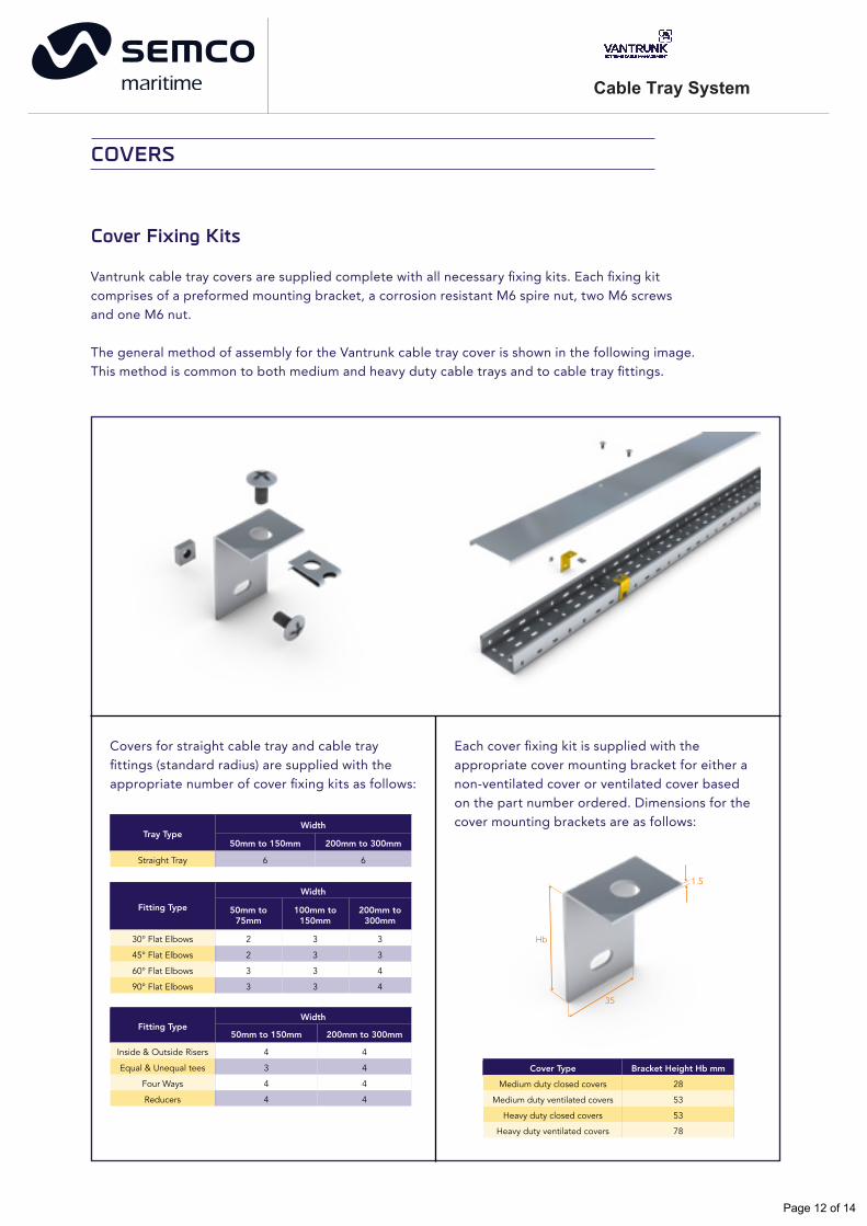
Cover Fixing Kits
Vantrunk cable tray covers are supplied complete with all necessary fixing kits. Each fixing kit comprises of a preformed mounting bracket, a corrosion resistant M6 spire nut, two M6 screws and one M6 nut.
The general method of assembly for the Vantrunk cable tray cover is shown in the following image. This method is common to both medium and heavy duty cable trays and to cable tray fittings.
Tray TypeWidth
50mm to 150mm 200mm to 300mm
Straight Tray 6 6
Fitting Type
Width
50mm to75mm
100mm to150mm
200mm to300mm
30° Flat Elbows 2 3 3
45° Flat Elbows 2 3 3
60° Flat Elbows 3 3 4
90° Flat Elbows 3 3 4
Fitting TypeWidth
50mm to 150mm 200mm to 300mm
4 4
3 4
4 4
Inside & Outside Risers
Equal & Unequal tees
Four Ways
Reducers 4 4
Covers for straight cable tray and cable tray fittings (standard radius) are supplied with the appropriate number of cover fixing kits as follows:
Each cover fixing kit is supplied with the appropriate cover mounting bracket for either a non-ventilated cover or ventilated cover based on the part number ordered. Dimensions for the cover mounting brackets are as follows:
Cover Type
Medium duty closed covers
Medium duty ventilated covers
Heavy duty closed covers
Heavy duty ventilated covers
Bracket Height Hb mm
28
53
53
78
Hb
1.5
35
COVERS
Page 12 of 14

Cable Tray System
Straight Tray Covers
Vantrunk straight tray covers are 3m in length and are available in widths of 50mm to 900mm as standard. Covers are common for both closed and ventilated applications.
Fitting Type: CC-SL3 or CV-SL3
Weights shown are for standard hot dip galvanised finish only, for Stainless Steel & Silicon Rich Steel weight conversion factors please refer to the Cable Tray technical section.
Fitting Covers
Vantrunk cable tray fitting covers are available in widths of 50mm to 900mm as standard. Covers are common for both closed and ventilated applications.
Tray Widthmm
Cover WidthWc mm
GaugeT mm
Weightkg
50 59
1.2
2.51
75 84 3.17
100 109 3.92
150 159 5.43
200 209 6.74
225 234 7.70
300 309 9.96
Straight Cable Tray Ventilated (Raised) Cover
Straight Cable Tray Closed (Non-Ventilated) Cover
Straight Cable Tray Cover Overall Dimensions & Fixing Centres
375
1475
375
WcT
11
Fitting Type: CC-Fitting Type or CV-Fitting Type
Order details for all fittings except risers are as follows:
Tray Type - Cover Type - Tray Fitting Type - Width - Radius - Finish & Material - Gauge.
Omit the radius detail if the standard radius fitting is required.
Order example:
HR-CV-FE30-300-150R-GA-1.2
Order example:
HR-CC-FE90-750-300R-SS-1.0
Vantrunk Heavy Duty Return Flange Cable Tray Ventilated Cover, 30° Flat Elbow, 300mm Wide, 150mm Radius, c/w Cover Fixing Kits, Hot Dip Galvanised Mild Steel, 1.2mm material thickness.
Vantrunk Heavy Duty Return Flange Cable Tray Closed Cover, 90° Flat Elbow, 750mm Wide, 300mm Radius, c/w Cover Fixing Kits, Stainless Steel (316 Grade), 1.0mm material thickness.
Covers for inside and outside riser fittings are supplied pre-formed to angles of 30°, 45°, 60° or 90° to match the angle of the riser.
Page 11 of 14Page 11 of 14
Page 13 of 14
Cable Tray System
GA SS GX GW
Part NumberDimensions mm Maximum
UDL KgTray La Lb A
AC-TCA-50- 50 60 50 N/A 100
AC-TCA-75- 75 85 50 N/A 100
AC-TCA-100- 100 110 50 N/A 100
AC-TCA-150- 150 160 90 45 150
AC-TCA-225- 225 235 90 45 150
AC-TCA-300- 300 310 90 45 150
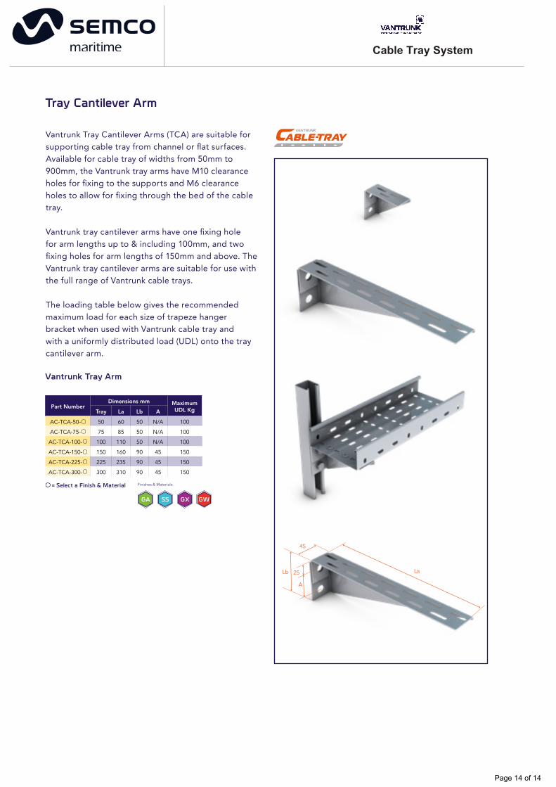
Tray Cantilever Arm
Vantrunk Tray Cantilever Arms (TCA) are suitable for supporting cable tray from channel or flat surfaces. Available for cable tray of widths from 50mm to 900mm, the Vantrunk tray arms have M10 clearance holes for fixing to the supports and M6 clearance holes to allow for fixing through the bed of the cable tray.
Vantrunk tray cantilever arms have one fixing hole for arm lengths up to & including 100mm, and two fixing holes for arm lengths of 150mm and above. The Vantrunk tray cantilever arms are suitable for use with the full range of Vantrunk cable trays.
The loading table below gives the recommended maximum load for each size of trapeze hanger bracket when used with Vantrunk cable tray and with a uniformly distributed load (UDL) onto the tray cantilever arm.
Vantrunk Tray Arm
Finishes & Materials: = Select a Finish & Material
45
LaLb 25
A
Page 14 of 14