c200h replacement guide - industrial automation replacement guide ... cp1h-x - cp1h-xa - ... cs/cj...
TRANSCRIPT
C200H Replacement Guide
From C200H to CJ2

About this document This document provides the reference information for replacing C200H PLC systems with CJ2 series PLC.
This document does not include precautions and reminders ;please read and understand the important precautions
and reminders described on the manuals of PLCs (both of PLC used in the existing system and PLC you will use to
replace the existing PLC) before attempting to start operation.
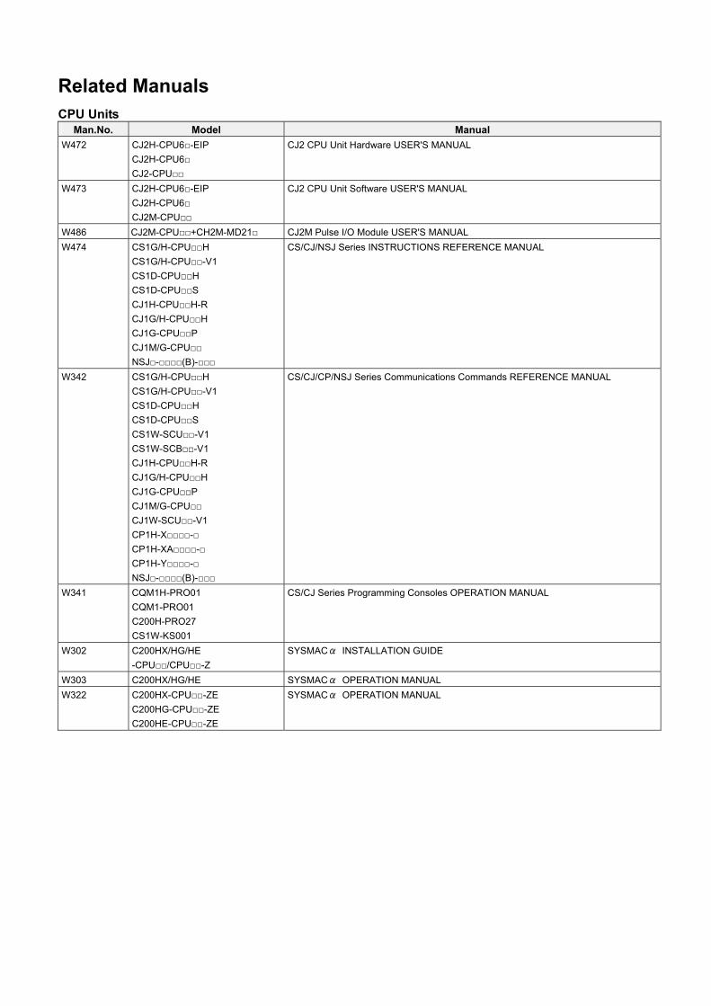
Related Manuals CPU Units
Man.No. Model Manual W472 CJ2H-CPU6-EIP
CJ2H-CPU6
CJ2-CPU
CJ2 CPU Unit Hardware USER'S MANUAL
W473 CJ2H-CPU6-EIP
CJ2H-CPU6
CJ2M-CPU
CJ2 CPU Unit Software USER'S MANUAL
W486 CJ2M-CPU+CH2M-MD21 CJ2M Pulse I/O Module USER'S MANUAL
W474 CS1G/H-CPUH
CS1G/H-CPU-V1
CS1D-CPUH
CS1D-CPUS
CJ1H-CPUH-R
CJ1G/H-CPUH
CJ1G-CPUP
CJ1M/G-CPU
NSJ-(B)-
CS/CJ/NSJ Series INSTRUCTIONS REFERENCE MANUAL
W342 CS1G/H-CPUH
CS1G/H-CPU-V1
CS1D-CPUH
CS1D-CPUS
CS1W-SCU-V1
CS1W-SCB-V1
CJ1H-CPUH-R
CJ1G/H-CPUH
CJ1G-CPUP
CJ1M/G-CPU
CJ1W-SCU-V1
CP1H-X-
CP1H-XA-
CP1H-Y-
NSJ-(B)-
CS/CJ/CP/NSJ Series Communications Commands REFERENCE MANUAL
W341 CQM1H-PRO01
CQM1-PRO01
C200H-PRO27
CS1W-KS001
CS/CJ Series Programming Consoles OPERATION MANUAL
W302 C200HX/HG/HE
-CPU/CPU-Z
SYSMACα INSTALLATION GUIDE
W303 C200HX/HG/HE SYSMACα OPERATION MANUAL
W322 C200HX-CPU-ZE
C200HG-CPU-ZE
C200HE-CPU-ZE
SYSMACα OPERATION MANUAL
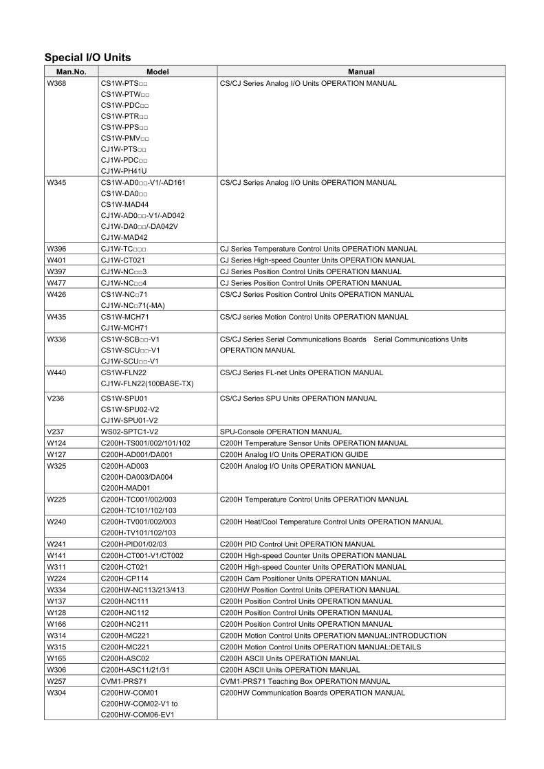
Special I/O Units
Man.No. Model Manual W368
CS1W-PTS
CS1W-PTW
CS1W-PDC
CS1W-PTR
CS1W-PPS
CS1W-PMV
CJ1W-PTS
CJ1W-PDC
CJ1W-PH41U
CS/CJ Series Analog I/O Units OPERATION MANUAL
W345
CS1W-AD0-V1/-AD161
CS1W-DA0
CS1W-MAD44
CJ1W-AD0-V1/-AD042
CJ1W-DA0/-DA042V
CJ1W-MAD42
CS/CJ Series Analog I/O Units OPERATION MANUAL
W396 CJ1W-TC CJ Series Temperature Control Units OPERATION MANUAL
W401 CJ1W-CT021 CJ Series High-speed Counter Units OPERATION MANUAL
W397 CJ1W-NC3 CJ Series Position Control Units OPERATION MANUAL
W477 CJ1W-NC4 CJ Series Position Control Units OPERATION MANUAL
W426 CS1W-NC71
CJ1W-NC71(-MA)
CS/CJ Series Position Control Units OPERATION MANUAL
W435 CS1W-MCH71
CJ1W-MCH71
CS/CJ series Motion Control Units OPERATION MANUAL
W336
CS1W-SCB-V1
CS1W-SCU-V1
CJ1W-SCU-V1
CS/CJ Series Serial Communications Boards Serial Communications Units
OPERATION MANUAL
W440 CS1W-FLN22
CJ1W-FLN22(100BASE-TX)
CS/CJ Series FL-net Units OPERATION MANUAL
V236 CS1W-SPU01
CS1W-SPU02-V2
CJ1W-SPU01-V2
CS/CJ Series SPU Units OPERATION MANUAL
V237 WS02-SPTC1-V2 SPU-Console OPERATION MANUAL
W124 C200H-TS001/002/101/102 C200H Temperature Sensor Units OPERATION MANUAL
W127 C200H-AD001/DA001 C200H Analog I/O Units OPERATION GUIDE
W325 C200H-AD003
C200H-DA003/DA004
C200H-MAD01
C200H Analog I/O Units OPERATION MANUAL
W225 C200H-TC001/002/003
C200H-TC101/102/103
C200H Temperature Control Units OPERATION MANUAL
W240 C200H-TV001/002/003
C200H-TV101/102/103
C200H Heat/Cool Temperature Control Units OPERATION MANUAL
W241 C200H-PID01/02/03 C200H PID Control Unit OPERATION MANUAL
W141 C200H-CT001-V1/CT002 C200H High-speed Counter Units OPERATION MANUAL
W311 C200H-CT021 C200H High-speed Counter Units OPERATION MANUAL
W224 C200H-CP114 C200H Cam Positioner Units OPERATION MANUAL
W334 C200HW-NC113/213/413 C200HW Position Control Units OPERATION MANUAL
W137 C200H-NC111 C200H Position Control Units OPERATION MANUAL
W128 C200H-NC112 C200H Position Control Units OPERATION MANUAL
W166 C200H-NC211 C200H Position Control Units OPERATION MANUAL
W314 C200H-MC221 C200H Motion Control Units OPERATION MANUAL:INTRODUCTION
W315 C200H-MC221 C200H Motion Control Units OPERATION MANUAL:DETAILS
W165 C200H-ASC02 C200H ASCII Units OPERATION MANUAL
W306 C200H-ASC11/21/31 C200H ASCII Units OPERATION MANUAL
W257 CVM1-PRS71 CVM1-PRS71 Teaching Box OPERATION MANUAL
W304 C200HW-COM01
C200HW-COM02-V1 to
C200HW-COM06-EV1
C200HW Communication Boards OPERATION MANUAL
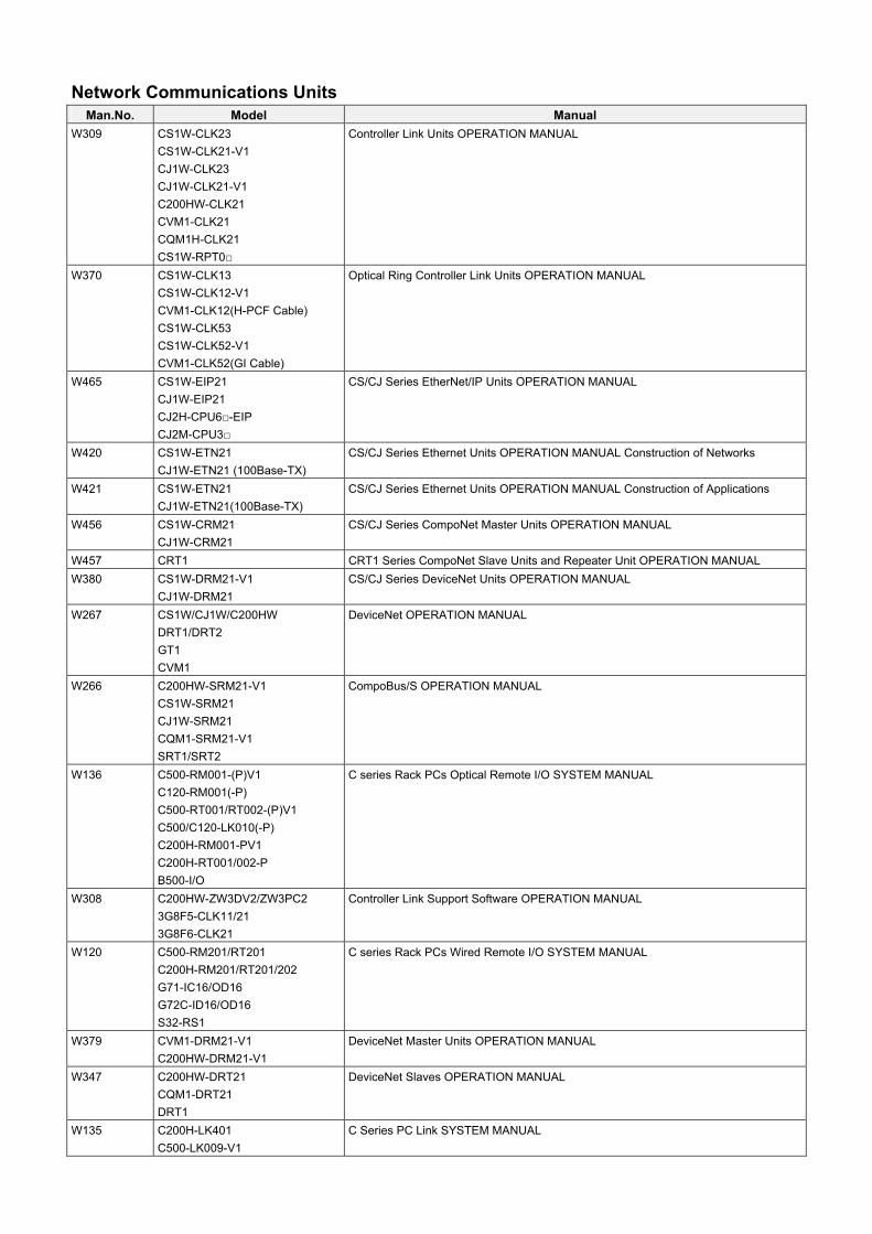
Network Communications Units Man.No. Model Manual
W309 CS1W-CLK23
CS1W-CLK21-V1
CJ1W-CLK23
CJ1W-CLK21-V1
C200HW-CLK21
CVM1-CLK21
CQM1H-CLK21
CS1W-RPT0
Controller Link Units OPERATION MANUAL
W370 CS1W-CLK13
CS1W-CLK12-V1
CVM1-CLK12(H-PCF Cable)
CS1W-CLK53
CS1W-CLK52-V1
CVM1-CLK52(GI Cable)
Optical Ring Controller Link Units OPERATION MANUAL
W465 CS1W-EIP21
CJ1W-EIP21
CJ2H-CPU6-EIP
CJ2M-CPU3
CS/CJ Series EtherNet/IP Units OPERATION MANUAL
W420 CS1W-ETN21
CJ1W-ETN21 (100Base-TX)
CS/CJ Series Ethernet Units OPERATION MANUAL Construction of Networks
W421 CS1W-ETN21
CJ1W-ETN21(100Base-TX)
CS/CJ Series Ethernet Units OPERATION MANUAL Construction of Applications
W456 CS1W-CRM21
CJ1W-CRM21
CS/CJ Series CompoNet Master Units OPERATION MANUAL
W457 CRT1 CRT1 Series CompoNet Slave Units and Repeater Unit OPERATION MANUAL
W380 CS1W-DRM21-V1
CJ1W-DRM21
CS/CJ Series DeviceNet Units OPERATION MANUAL
W267 CS1W/CJ1W/C200HW
DRT1/DRT2
GT1
CVM1
DeviceNet OPERATION MANUAL
W266 C200HW-SRM21-V1
CS1W-SRM21
CJ1W-SRM21
CQM1-SRM21-V1
SRT1/SRT2
CompoBus/S OPERATION MANUAL
W136 C500-RM001-(P)V1
C120-RM001(-P)
C500-RT001/RT002-(P)V1
C500/C120-LK010(-P)
C200H-RM001-PV1
C200H-RT001/002-P
B500-I/O
C series Rack PCs Optical Remote I/O SYSTEM MANUAL
W308 C200HW-ZW3DV2/ZW3PC2
3G8F5-CLK11/21
3G8F6-CLK21
Controller Link Support Software OPERATION MANUAL
W120 C500-RM201/RT201
C200H-RM201/RT201/202
G71-IC16/OD16
G72C-ID16/OD16
S32-RS1
C series Rack PCs Wired Remote I/O SYSTEM MANUAL
W379 CVM1-DRM21-V1
C200HW-DRM21-V1
DeviceNet Master Units OPERATION MANUAL
W347 C200HW-DRT21
CQM1-DRT21
DRT1
DeviceNet Slaves OPERATION MANUAL
W135 C200H-LK401
C500-LK009-V1
C Series PC Link SYSTEM MANUAL

Support Software
Man.No. Model Manual W463 CX-One FA Integrated Tool Package SETUP MANUAL
W446 CX-Programmer OPERATION MANUAL
W447 CX-Programmer OPERATION MANUAL : Function Blocks/Structured Text
W366 CX-Simulator OPERATION MANUAL
W464 CX-Integrator OPERATION MANUAL
W344 CX-Protocol OPERATION MANUAL
W433 CX-Position OPERATION MANUAL
W436 CX-Motion-NCF OPERATION MANUAL
W448
CXONE-ALC-V4
CXONE-ALD-V4
CX-Motion-MCH OPERATION MANUAL
Read and Understand this DocumentPlease read and understand this document before using the product. Please consult your OMRON representative if you have any questions or comments.
Warranty and Limitations of Liability
WARRANTY
OMRON's exclusive warranty is that the products are free from defects in materials and workmanship for a period of one year (or other period if specified) from date of sale by OMRON.
OMRON MAKES NO WARRANTY OR REPRESENTATION, EXPRESS OR IMPLIED, REGARDING NON-INFRINGEMENT, MERCHANTABILITY, OR FITNESS FOR PARTICULAR PURPOSE OF THE PRODUCTS. ANY BUYER OR USER ACKNOWLEDGES THAT THE BUYER OR USER ALONE HAS DETERMINED THAT THE PRODUCTS WILL SUITABLY MEET THE REQUIREMENTS OF THEIR INTENDED USE. OMRON DISCLAIMS ALL OTHER WARRANTIES, EXPRESS OR IMPLIED.
LIMITATIONS OF LIABILITY
OMRON SHALL NOT BE RESPONSIBLE FOR SPECIAL, INDIRECT, OR CONSEQUENTIAL DAMAGES, LOSS OF PROFITS OR COMMERCIAL LOSS IN ANY WAY CONNECTED WITH THE PRODUCTS, WHETHER SUCH CLAIM IS BASED ON CONTRACT, WARRANTY, NEGLIGENCE, OR STRICT LIABILITY.
In no event shall the responsibility of OMRON for any act exceed the individual price of the product on which liability is asserted.
IN NO EVENT SHALL OMRON BE RESPONSIBLE FOR WARRANTY, REPAIR, OR OTHER CLAIMS REGARDING THE PRODUCTS UNLESS OMRON'S ANALYSIS CONFIRMS THAT THE PRODUCTS WERE PROPERLY HANDLED, STORED, INSTALLED, AND MAINTAINED AND NOT SUBJECT TO CONTAMINATION, ABUSE, MISUSE, OR INAPPROPRIATE MODIFICATION OR REPAIR.
Disclaimers
CHANGE IN SPECIFICATIONS
Product specifications and accessories may be changed at any time based on improvements and other reasons.
It is our practice to change model numbers when published ratings or features are changed, or when significant construction changes are made. However, some specifications of the products may be changed without any notice. When in doubt, special model numbers may be assigned to fix or establish key specifications for your application on your request. Please consult with your OMRON representative at any time to confirm actual specifications of purchased products.
DIMENSIONS AND WEIGHTS
Dimensions and weights are nominal and are not to be used for manufacturing purposes, even when tolerances are shown.
PERFORMANCE DATA
Performance data given in this manual is provided as a guide for the user in determining suitability and does not constitute a warranty. It may represent the result of OMRON's test conditions, and the users must correlate it to actual application requirements. Actual performance is subject to the OMRON Warranty and Limitations of Liability.
ERRORS AND OMISSIONS
The information in this manual has been carefully checked and is believed to be accurate; however, no responsibility is assumed for clerical, typographical, or proofreading errors, or omissions.
Application Considerations
SUITABILITY FOR USE
OMRON shall not be responsible for conformity with any standards, codes, or regulations that apply to the combination of products in the customer's application or use of the products.
At the customer's request, OMRON will provide applicable third party certification documents identifying ratings and limitations of use that apply to the products. This information by itself is not sufficient for a complete determination of the suitability of the products in combination with the end product, machine, system, or other application or use.
The following are some examples of applications for which particular attention must be given. This is not intended to be an exhaustive list of all possible uses of the products, nor is it intended to imply that the uses listed may be suitable for the products:
• Outdoor use, uses involving potential chemical contamination or electrical interference, or conditions or uses not described in this manual.
• Nuclear energy control systems, combustion systems, railroad systems, aviation systems, medical equipment, amusement machines, vehicles, safety equipment, and installations subject to separate industry or government regulations.
• Systems, machines, and equipment that could present a risk to life or property.
Please know and observe all prohibitions of use applicable to the products.
NEVER USE THE PRODUCTS FOR AN APPLICATION INVOLVING SERIOUS RISK TO LIFE OR PROPERTY WITHOUT ENSURING THAT THE SYSTEM AS A WHOLE HAS BEEN DESIGNED TO ADDRESS THE RISKS, AND THAT THE OMRON PRODUCTS ARE PROPERLY RATED AND INSTALLED FOR THE INTENDED USE WITHIN THE OVERALL EQUIPMENT OR SYSTEM.
PROGRAMMABLE PRODUCTS
OMRON shall not be responsible for the user's programming of a programmable product, or any consequence thereof.

MEMO
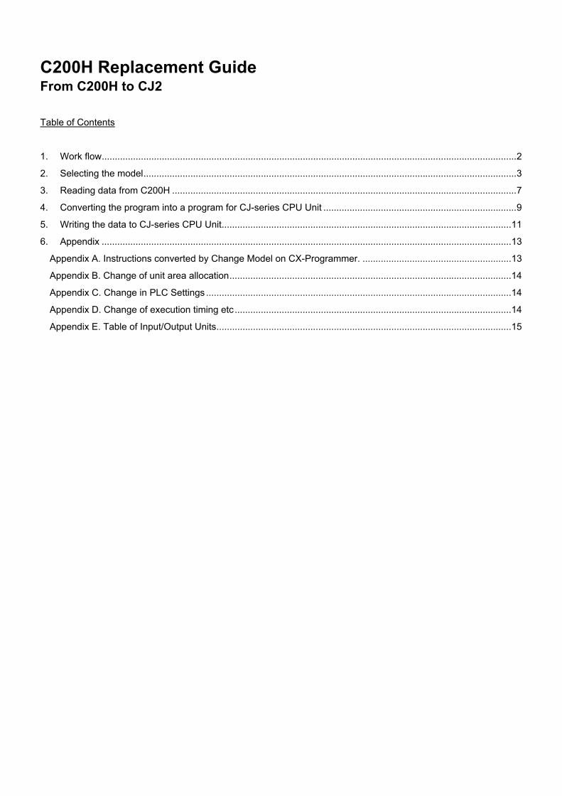
C200H Replacement Guide From C200H to CJ2
Table of Contents
1. Work flow...............................................................................................................................................................2
2. Selecting the model...............................................................................................................................................3
3. Reading data from C200H ....................................................................................................................................7
4. Converting the program into a program for CJ-series CPU Unit ..........................................................................9
5. Writing the data to CJ-series CPU Unit...............................................................................................................11
6. Appendix .............................................................................................................................................................13
Appendix A. Instructions converted by Change Model on CX-Programmer. .........................................................13
Appendix B. Change of unit area allocation............................................................................................................14
Appendix C. Change in PLC Settings .....................................................................................................................14
Appendix D. Change of execution timing etc..........................................................................................................14
Appendix E. Table of Input/Output Units.................................................................................................................15
1
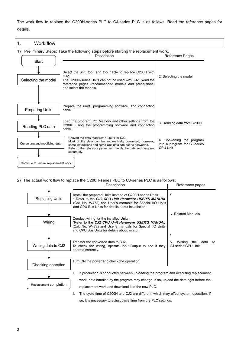
The work flow to replace the C200H-series PLC to CJ-series PLC is as follows. Read the reference pages for
details.
1. Work flow
1) Preliminary Steps: Take the following steps before starting the replacement work.
Selecting the model
Reading PLC data
Description Reference Pa ges
Select the unit, tool, and tool cable to replace C200H with CJ2. The C200H-series Units can not be used with CJ2. Read the reference pages (recommended models and precautions) and select the models.
Load the program, I/O Memory and other settings from the C200H using the programming software and connectingcable.
Converting and modifying data
Convert the data read from C200H for CJ2. Most of the data can be automatically converted; however, some instructions and some Unit data can not be converted. Refer to the reference pages and modify the data and program separately.
2. Selecting the model
3. Reading data from C200H
Preparing Units Prepare the units, programming software, and connectingcable.
4. Converting the program into a program for CJ-series CPU Unit
Continue to actual replacement work
Start
2) The actual work flow to replace the C200H-series PLC to CJ-series PLC is as follows.
Replacing Units
Writing data to CJ2
Description Reference pages
Install the prepared Units instead of C200H-series Units. * Refer to the CJ2 CPU Unit Hardware USER'S MANUAL(Cat. No. W472) and User's manuals for Special I/O Unitsand CPU Bus Units for details about installation.
Transfer the converted data to CJ2. To check the wiring, operate Input/Output to see if they operate correctly.
Checking operation Turn ON the power and check the operation.
Related Manuals
Wiring Conduct wiring for the installed Units. *Refer to the CJ2 CPU Unit Hardware USER'S MANUAL(Cat. No. W472) and User's manuals for Special I/O Units and CPU Bus Units for details about wiring.
5. Writing the data toCJ-series CPU Unit
Replacement completion
1. If production is conducted between uploading the program and executing replacement
work, data handled by the program may change. If so, upload the data right before the
replacement work and download it to the new PLC.
2. The cycle time of C200H and CJ2 are different, which may effect system operation. If
so, it is necessary to adjust cycle time from the PLC settings.
2
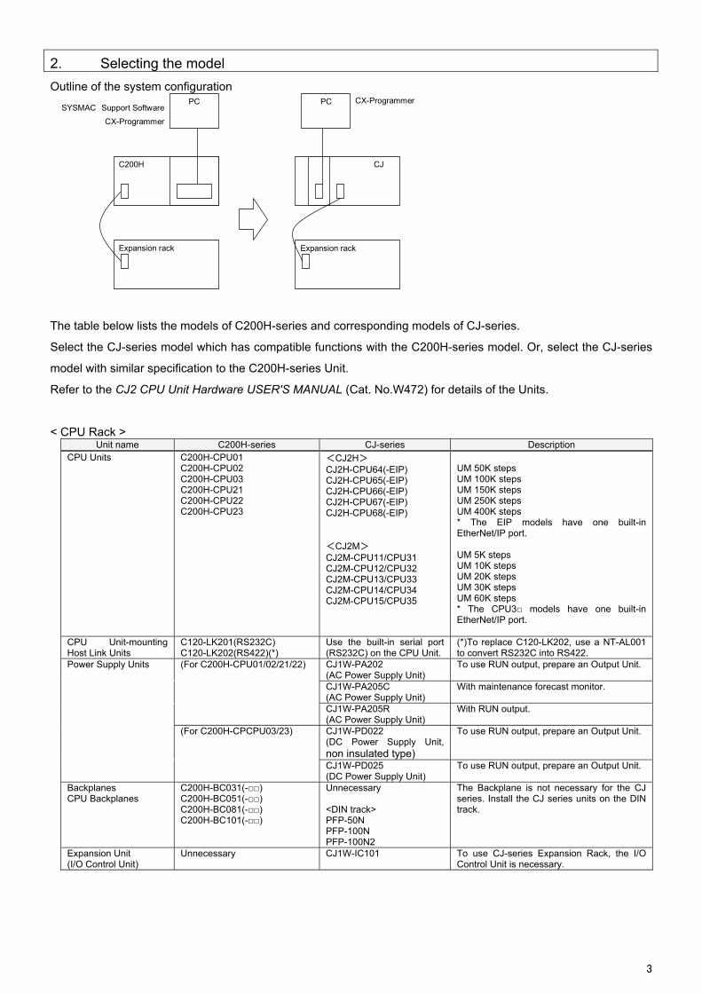
2. Selecting the model
Outline of the system configuration
C200H
PC
Expansion rack
CJ
PC
Expansion rack
SYSMAC Support Software
CX-Programmer
CX-Programmer
The table below lists the models of C200H-series and corresponding models of CJ-series.
Select the CJ-series model which has compatible functions with the C200H-series model. Or, select the CJ-series
model with similar specification to the C200H-series Unit.
Refer to the CJ2 CPU Unit Hardware USER'S MANUAL (Cat. No.W472) for details of the Units.
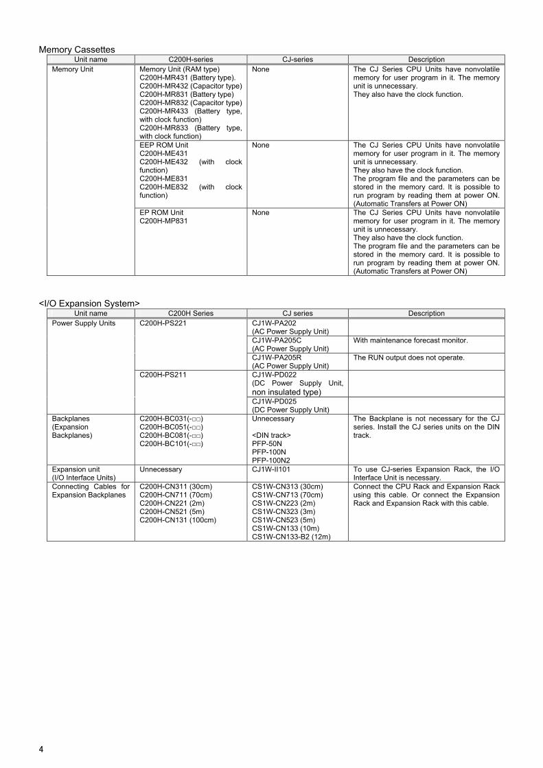
< CPU Rack > Unit name C200H-series CJ-series Description
CPU Units C200H-CPU01 C200H-CPU02 C200H-CPU03 C200H-CPU21 C200H-CPU22 C200H-CPU23
<CJ2H> CJ2H-CPU64(-EIP) CJ2H-CPU65(-EIP) CJ2H-CPU66(-EIP) CJ2H-CPU67(-EIP) CJ2H-CPU68(-EIP) <CJ2M> CJ2M-CPU11/CPU31 CJ2M-CPU12/CPU32 CJ2M-CPU13/CPU33 CJ2M-CPU14/CPU34 CJ2M-CPU15/CPU35
UM 50K steps UM 100K steps UM 150K steps UM 250K steps UM 400K steps * The EIP models have one built-in EtherNet/IP port. UM 5K steps UM 10K steps UM 20K steps UM 30K steps UM 60K steps * The CPU3 models have one built-in EtherNet/IP port.
CPU Unit-mounting Host Link Units
C120-LK201(RS232C) C120-LK202(RS422)(*)
Use the built-in serial port (RS232C) on the CPU Unit.
(*)To replace C120-LK202, use a NT-AL001 to convert RS232C into RS422.
Power Supply Units
(For C200H-CPU01/02/21/22) CJ1W-PA202 (AC Power Supply Unit)
To use RUN output, prepare an Output Unit.
CJ1W-PA205C (AC Power Supply Unit)
With maintenance forecast monitor.
CJ1W-PA205R (AC Power Supply Unit)
With RUN output.
(For C200H-CPCPU03/23) CJ1W-PD022 (DC Power Supply Unit, non insulated type)
To use RUN output, prepare an Output Unit.
CJ1W-PD025 (DC Power Supply Unit)
To use RUN output, prepare an Output Unit.
Backplanes CPU Backplanes
C200H-BC031(-) C200H-BC051(-) C200H-BC081(-) C200H-BC101(-)
Unnecessary <DIN track> PFP-50N PFP-100N PFP-100N2
The Backplane is not necessary for the CJ series. Install the CJ series units on the DIN track.
Expansion Unit (I/O Control Unit)
Unnecessary CJ1W-IC101 To use CJ-series Expansion Rack, the I/O Control Unit is necessary.
3
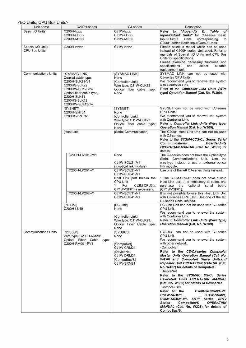
Memory Cassettes Unit name C200H-series CJ-series Description
Memory Unit Memory Unit (RAM type) C200H-MR431 (Battery type). C200H-MR432 (Capacitor type)C200H-MR831 (Battery type) C200H-MR832 (Capacitor type)C200H-MR433 (Battery type, with clock function) C200H-MR833 (Battery type, with clock function)
None The CJ Series CPU Units have nonvolatile memory for user program in it. The memory unit is unnecessary. They also have the clock function.
EEP ROM Unit C200H-ME431 C200H-ME432 (with clock function) C200H-ME831 C200H-ME832 (with clock function)
None The CJ Series CPU Units have nonvolatile memory for user program in it. The memory unit is unnecessary. They also have the clock function. The program file and the parameters can be stored in the memory card. It is possible to run program by reading them at power ON. (Automatic Transfers at Power ON)
EP ROM Unit C200H-MP831
None The CJ Series CPU Units have nonvolatile memory for user program in it. The memory unit is unnecessary. They also have the clock function. The program file and the parameters can be stored in the memory card. It is possible to run program by reading them at power ON. (Automatic Transfers at Power ON)
<I/O Expansion System> Unit name C200H Series CJ series Description
Power Supply Units
C200H-PS221 CJ1W-PA202 (AC Power Supply Unit)
CJ1W-PA205C (AC Power Supply Unit)
With maintenance forecast monitor.
CJ1W-PA205R (AC Power Supply Unit)
The RUN output does not operate.
C200H-PS211 CJ1W-PD022 (DC Power Supply Unit, non insulated type)
CJ1W-PD025 (DC Power Supply Unit)
Backplanes (Expansion Backplanes)
C200H-BC031(-) C200H-BC051(-) C200H-BC081(-) C200H-BC101(-)
Unnecessary <DIN track> PFP-50N PFP-100N PFP-100N2
The Backplane is not necessary for the CJ series. Install the CJ series units on the DIN track.
Expansion unit (I/O Interface Units)
Unnecessary CJ1W-II101 To use CJ-series Expansion Rack, the I/O Interface Unit is necessary.
Connecting Cables for Expansion Backplanes
C200H-CN311 (30cm) C200H-CN711 (70cm) C200H-CN221 (2m) C200H-CN521 (5m) C200H-CN131 (100cm)
CS1W-CN313 (30cm) CS1W-CN713 (70cm) CS1W-CN223 (2m) CS1W-CN323 (3m) CS1W-CN523 (5m) CS1W-CN133 (10m) CS1W-CN133-B2 (12m)
Connect the CPU Rack and Expansion Rack using this cable. Or connect the Expansion Rack and Expansion Rack with this cable.
4
<I/O Units, CPU Bus Units> Unit name C200H-series CJ-series Description
Basic I/O Units C200H-I C200H-O C200H-M
CJ1W-I CJ1W-O CJ1W-M
Refer to "Appendix E. Table of Input/Output Units" for CJ-series Basic Input/Output Units corresponding to C200H-series Basic Input/Output Units.
Special I/O Units CPU Bus Units
C200H- CJ1W- Please select a model which can be used instead of C200H-series Unit used. Refer to manuals of Special I/O Units and CPU Bus Units for specifications. Please examine necessary functions and specifications and select suitable replacement unit.
Communications Units SYSMAC LINK Coaxial cable type: C200H-SLK21-V1 C200HS-SLK22 C200HW-SLK23/24 Optical fiber cable type: C200H-SLK11 C200HS-SLK12 C200HW-SLK13/14
SYSMAC LINK None Controller Link Wire type: CJ1W-CLK23 Optical fiber cable type: None
SYSMAC LINK can not be used with CJ-series CPU Units. We recommend you to renewal the system with Controller Link. Refer to the Controller Link Units (Wire type) Operation Manual (Cat. No. W309).
SYSNET C200H-SNT31 C200HS-SNT32
SYSNET None Controller Link Wire type: CJ1W-CLK23. Optical fiber cable type: None
SYSNET can not be used with CJ-series CPU Units. We recommend you to renewal the system with Controller Link. Refer to Controller Link Units (Wire type) Operation Manual (Cat, No. W309).
[Host Link] [Serial Communication] The C200H Host Link Unit can not be used with CJ-series. Refer to the SYSMACCS/CJ Series Serial Communications Boards/Units OPERATIAN MANUAL (Cat. No. W336) for details.
C200H-LK101-PV1 None CJ1W-SCU21-V1 (+ optical link module)
The CJ-series does not have the Optical-type Serial Communications Unit. Use the wire-type instead, or use an external optical link module.
C200H-LK201-V1 CJ1W-SCU21-V1 CJ1W-SCU41-V1 Host Link port built-in the CPU Unit * For CJ2M-CPU3, CP1W-CIF01 is necessary.
Use one of the left CJ-series Units instead. * The CJ2M-CPU3 does not have built-in Host Link port. It is necessary to select and purchase the optional serial board (CP1W-CIF01).
C200H-LK202-V1 CJ1W-SCU31-V1 CJ1W-SCU41-V1
It is not possible to use this Host Link Unit with CJ-series CPU Unit. Use one of the left CJ-series Units, instead.
[PC Link] C200H-LK401
[PC Link] None Controller Link] Wire type: CJ1W-CLK23. Optical Fiber Cable type:None
PC Link Unit can not be used with CJ-series CPU Unit. We recommend you to renewal the system with Controller Link. Refer to Controller Link Units (Wire type) Operation Manual (Cat, No. W309).
Communications Units SYSBUS] Wire type: C200H-RM201 Optical Fiber Cable type:C200H-RM001-PV1
SYSBUS] None CompoNet] CJ1W-CRM21 DeviceNet] CJ1W-DRM21 CompoBus/S] CJ1W-SRM21
SYSBUS can not be used with CJ-series CPU Unit. We recommend you to renewal the system with other network. ・CompoNet Refer to the CS/CJ-series CompoNet Master Units Operation Manual (Cat. No. W456) and CompoNet Slave Unitsand Repeater Unit OPERATION MANUAL (Cat. No. W457) for details of CompoNet. ・DeviceNet Refer to the SYSMAC CS/CJ Series DeviceNet Units OPERATIAN MANUAL (Cat. No. W380) for details of DeviceNet. ・CompoBus/S Refer to the C200HW-SRM21-V1, CS1W-SRM21, CJ1W-SRM21, CQM1-SRM21-V1, SRT1 Series, SRT2 Series CompoBus/S OPERATIAN MANUAL (Cat. No. W226) for details of CompoBus/S.
5
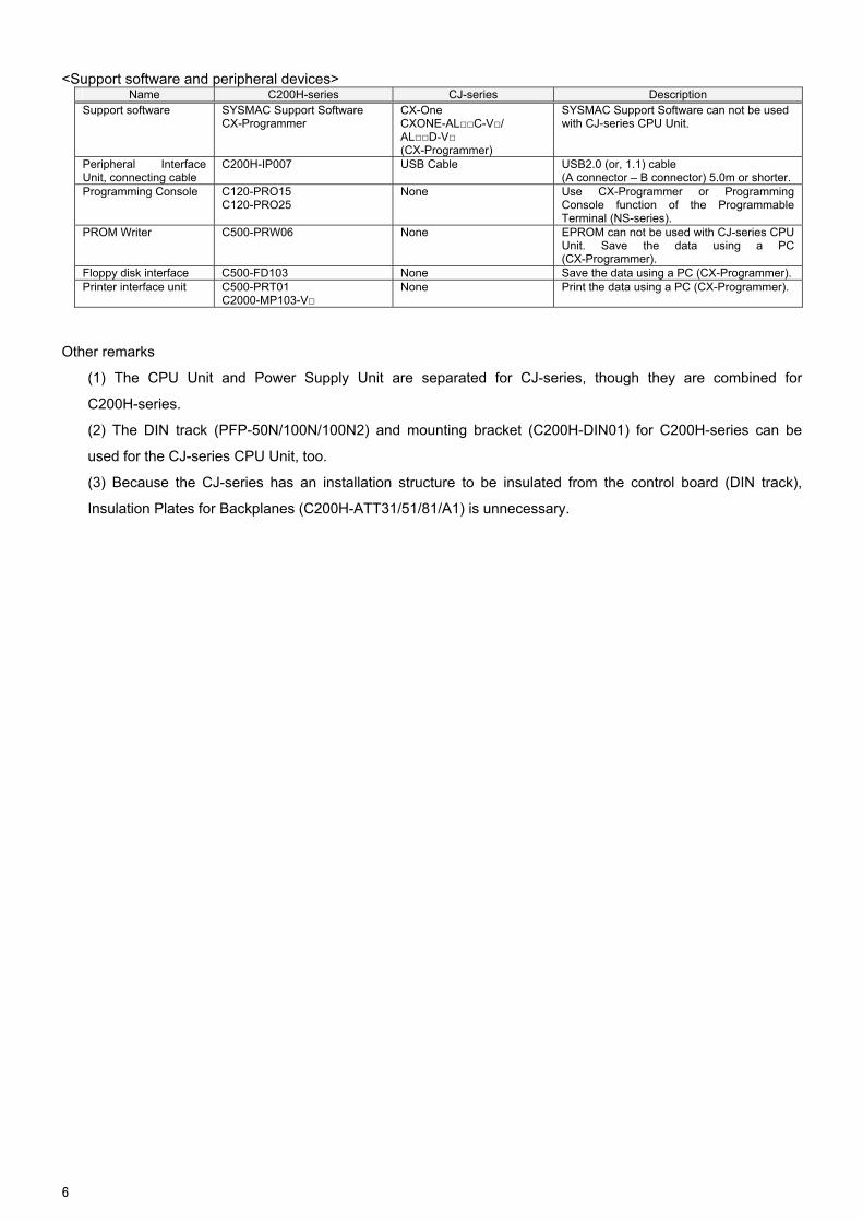
<Support software and peripheral devices> Name C200H-series CJ-series Description
Support software SYSMAC Support Software CX-Programmer
CX-One CXONE-ALC-V/ ALD-V (CX-Programmer)
SYSMAC Support Software can not be used with CJ-series CPU Unit.
Peripheral Interface Unit, connecting cable
C200H-IP007 USB Cable USB2.0 (or, 1.1) cable (A connector – B connector) 5.0m or shorter.
Programming Console C120-PRO15 C120-PRO25
None Use CX-Programmer or Programming Console function of the Programmable Terminal (NS-series).
PROM Writer C500-PRW06 None EPROM can not be used with CJ-series CPU Unit. Save the data using a PC (CX-Programmer).
Floppy disk interface C500-FD103 None Save the data using a PC (CX-Programmer). Printer interface unit C500-PRT01
C2000-MP103-V None Print the data using a PC (CX-Programmer).
Other remarks
(1) The CPU Unit and Power Supply Unit are separated for CJ-series, though they are combined for
C200H-series.
(2) The DIN track (PFP-50N/100N/100N2) and mounting bracket (C200H-DIN01) for C200H-series can be
used for the CJ-series CPU Unit, too.
(3) Because the CJ-series has an installation structure to be insulated from the control board (DIN track),
Insulation Plates for Backplanes (C200H-ATT31/51/81/A1) is unnecessary.
6
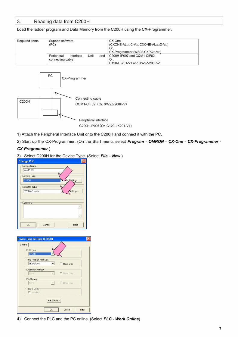
3. Reading data from C200H
Load the ladder program and Data Memory from the C200H using the CX-Programmer.
Required items Support software
(PC) CX-One (CXONE-ALC-V, CXONE-ALD-V) Or, CX-Programmer (WS02-CXPC-V)
Peripheral Interface Unit and connecting cable
C200H-IP007 and CQM1-CIF02 Or, C120-LK201-V1 and XW2Z-200P-V
C200H
PC CX-Programmer
Connecting cable
CQM1-CIF02 (Or, XW2Z-200P-V)
Peripheral interface
C200H-IP007(Or, C120-LK201-V1)
1) Attach the Peripheral Interface Unit onto the C200H and connect it with the PC.
2) Start up the CX-Programmer. (On the Start menu, select Program - OMRON - CX-One - CX-Programmer -
CX-Programmer.)
3) Select C200H for the Device Type. (Select File – New.)
4) Connect the PLC and the PC online. (Select PLC - Work Online)
7
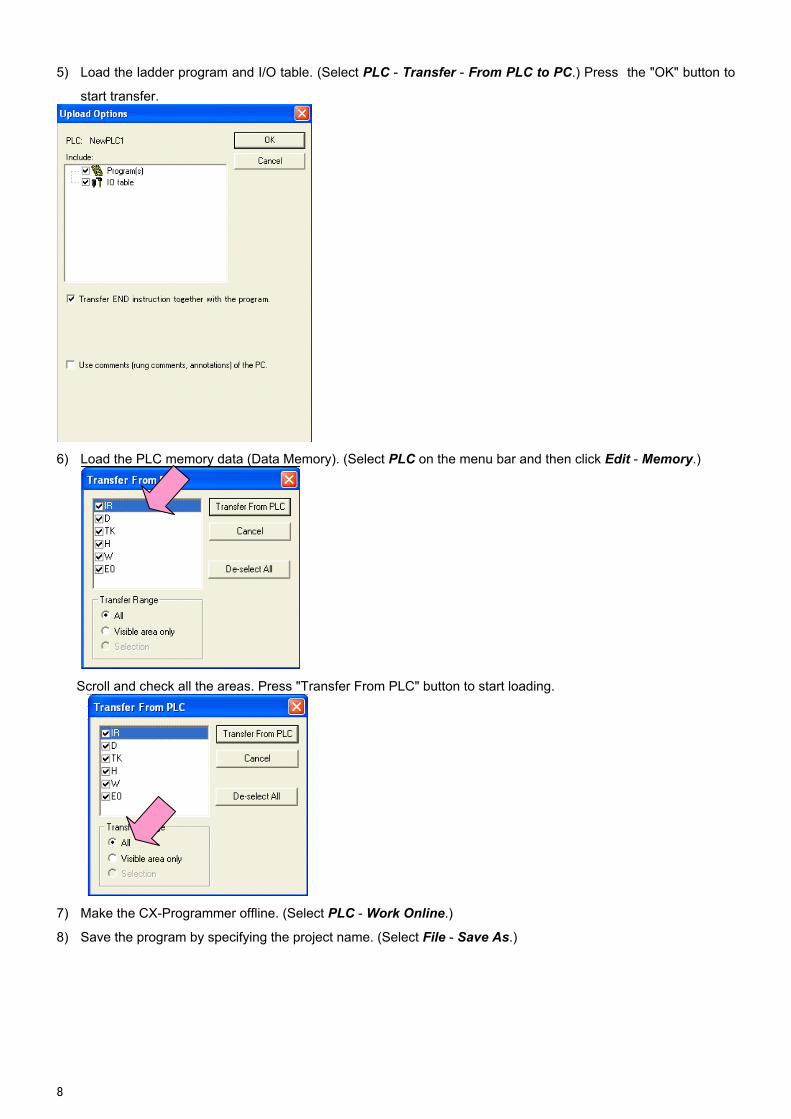
5) Load the ladder program and I/O table. (Select PLC - Transfer - From PLC to PC.) Press the "OK" button to
start transfer.
6) Load the PLC memory data (Data Memory). (Select PLC on the menu bar and then click Edit - Memory.)
Scroll and check all the areas. Press "Transfer From PLC" button to start loading.
7) Make the CX-Programmer offline. (Select PLC - Work Online.)
8) Save the program by specifying the project name. (Select File - Save As.)
8
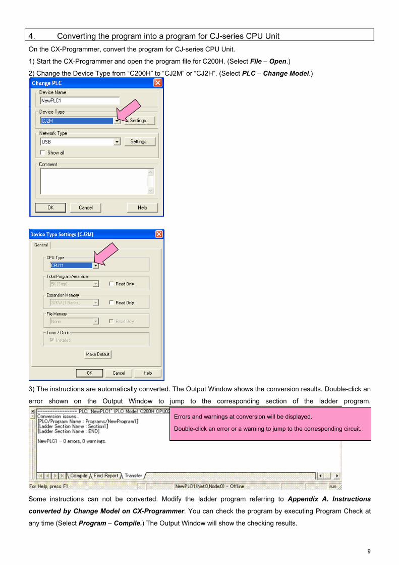
4. Converting the program into a program for CJ-series CPU Unit
On the CX-Programmer, convert the program for CJ-series CPU Unit.
1) Start the CX-Programmer and open the program file for C200H. (Select File – Open.)
2) Change the Device Type from “C200H” to “CJ2M” or “CJ2H”. (Select PLC – Change Model.)
3) The instructions are automatically converted. The Output Window shows the conversion results. Double-click an
error shown on the Output Window to jump to the corresponding section of the ladder program.
Errors and warnings at conversion will be displayed.
Double-click an error or a warning to jump to the corresponding circuit.
Some instructions can not be converted. Modify the ladder program referring to Appendix A. Instructions
converted by Change Model on CX-Programmer. You can check the program by executing Program Check at
any time (Select Program – Compile.) The Output Window will show the checking results.
9
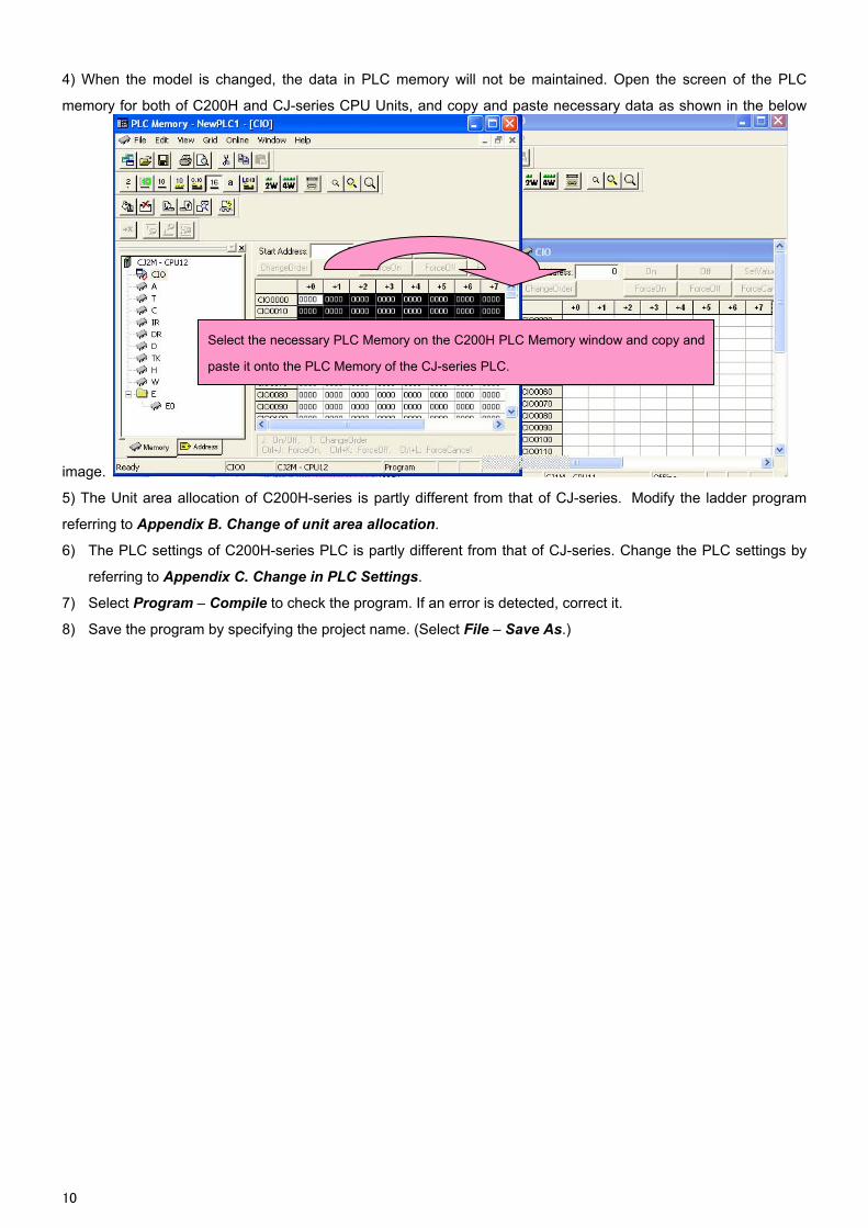
4) When the model is changed, the data in PLC memory will not be maintained. Open the screen of the PLC
memory for both of C200H and CJ-series CPU Units, and copy and paste necessary data as shown in the below
image.
Select the necessary PLC Memory on the C200H PLC Memory window and copy and
paste it onto the PLC Memory of the CJ-series PLC.
5) The Unit area allocation of C200H-series is partly different from that of CJ-series. Modify the ladder program
referring to Appendix B. Change of unit area allocation.
6) The PLC settings of C200H-series PLC is partly different from that of CJ-series. Change the PLC settings by
referring to Appendix C. Change in PLC Settings.
7) Select Program – Compile to check the program. If an error is detected, correct it.
8) Save the program by specifying the project name. (Select File – Save As.)
10
5. Writing the data to CJ-series CPU Unit
Transfer the converted/modified program, PLC settings and Data Memory to the CJ-series CPU Unit. Required items Support software
(PC) CX-One CXONE-ALC-V/ ALD-V (CX-Programmer)
Connecting cable USB Cable USB2.0 (or, 1.1) cable (A connector – B connector) 5.0m or shorter
CJ
PC CX-Programmer
Connecting cable
USB cable
Peripheral port (USB) on
CPU Unit.
1) Connect the CJ-series CPU Unit and the PC.
2) Start the CX-Programmer and open the converted program file.
3) Connect the CJ-series CPU Unit and CX-Programmer online.
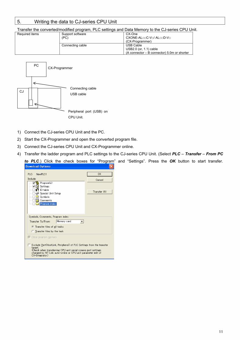
4) Transfer the ladder program and PLC settings to the CJ-series CPU Unit. (Select PLC – Transfer – From PC
to PLC.) Click the check boxes for “Program” and “Settings”. Press the OK button to start transfer.
11
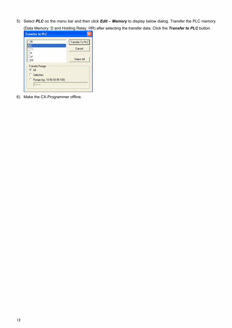
5) Select PLC on the menu bar and then click Edit – Memory to display below dialog. Transfer the PLC memory
(Data Memory: D and Holding Relay: HR) after selecting the transfer data. Click the Transfer to PLC button.
6) Make the CX-Programmer offline.
12
6. Appendix
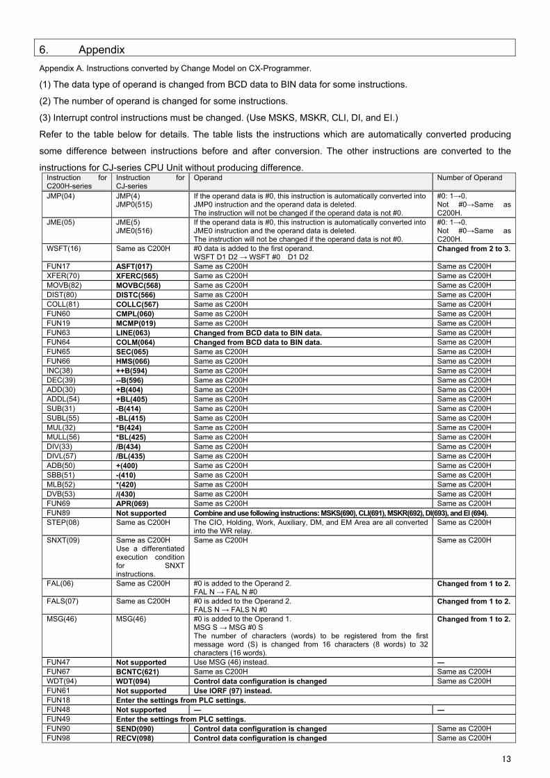
Appendix A. Instructions converted by Change Model on CX-Programmer.
(1) The data type of operand is changed from BCD data to BIN data for some instructions.
(2) The number of operand is changed for some instructions.
(3) Interrupt control instructions must be changed. (Use MSKS, MSKR, CLI, DI, and EI.)
Refer to the table below for details. The table lists the instructions which are automatically converted producing
some difference between instructions before and after conversion. The other instructions are converted to the
instructions for CJ-series CPU Unit without producing difference. Instruction for C200H-series
Instruction for CJ-series
Operand Number of Operand
JMP(04) JMP(4) JMP0(515)
If the operand data is #0, this instruction is automatically converted into JMP0 instruction and the operand data is deleted. The instruction will not be changed if the operand data is not #0.
#0: 1→0. Not #0→Same as C200H.
JME(05) JME(5) If the operand data is #0, this instruction is automatically converted into JME0 instruction and the operand data is deleted. The instruction will not be changed if the operand data is not #0.
#0: 1→0. Not #0→Same as C200H.
JME0(516)
WSFT(16) Same as C200H #0 data is added to the first operand. WSFT D1 D2 → WSFT #0 D1 D2
Changed from 2 to 3.
FUN17 ASFT(017) Same as C200H Same as C200H XFER(70) XFERC(565) Same as C200H Same as C200H MOVB(82) MOVBC(568) Same as C200H Same as C200H DIST(80) DISTC(566) Same as C200H Same as C200H COLL(81) COLLC(567) Same as C200H Same as C200H FUN60 CMPL(060) Same as C200H Same as C200H FUN19 MCMP(019) Same as C200H Same as C200H FUN63 LINE(063) Changed from BCD data to BIN data. Same as C200H FUN64 COLM(064) Changed from BCD data to BIN data. Same as C200H FUN65 SEC(065) Same as C200H Same as C200H FUN66 HMS(066) Same as C200H Same as C200H INC(38) ++B(594) Same as C200H Same as C200H DEC(39) --B(596) Same as C200H Same as C200H ADD(30) +B(404) Same as C200H Same as C200H ADDL(54) +BL(405) Same as C200H Same as C200H SUB(31) -B(414) Same as C200H Same as C200H SUBL(55) -BL(415) Same as C200H Same as C200H MUL(32) *B(424) Same as C200H Same as C200H MULL(56) *BL(425) Same as C200H Same as C200H DIV(33) /B(434) Same as C200H Same as C200H DIVL(57) /BL(435) Same as C200H Same as C200H ADB(50) +(400) Same as C200H Same as C200H SBB(51) -(410) Same as C200H Same as C200H MLB(52) *(420) Same as C200H Same as C200H DVB(53) /(430) Same as C200H Same as C200H FUN69 APR(069) Same as C200H Same as C200H FUN89 Not supported Combine and use following instructions: MSKS(690), CLI(691), MSKR(692), DI(693), and EI (694). STEP(08) Same as C200H The CIO, Holding, Work, Auxiliary, DM, and EM Area are all converted
into the WR relay. Same as C200H
SNXT(09) Same as C200H Use a differentiated execution condition for SNXT instructions.
Same as C200H Same as C200H
FAL(06) Same as C200H #0 is added to the Operand 2. FAL N → FAL N #0
Changed from 1 to 2.
FALS(07) Same as C200H #0 is added to the Operand 2. FALS N → FALS N #0
Changed from 1 to 2.
MSG(46) MSG(46) #0 is added to the Operand 1. MSG S → MSG #0 S The number of characters (words) to be registered from the first message word (S) is changed from 16 characters (8 words) to 32 characters (16 words).
Changed from 1 to 2.
FUN47 Not supported Use MSG (46) instead. ― FUN67 BCNTC(621) Same as C200H Same as C200H WDT(94) WDT(094) Control data configuration is changed Same as C200H FUN61 Not supported Use IORF (97) instead. FUN18 Enter the settings from PLC settings. FUN48 Not supported ― ― FUN49 Enter the settings from PLC settings. FUN90 SEND(090) Control data configuration is changed Same as C200H FUN98 RECV(098) Control data configuration is changed Same as C200H
13
14
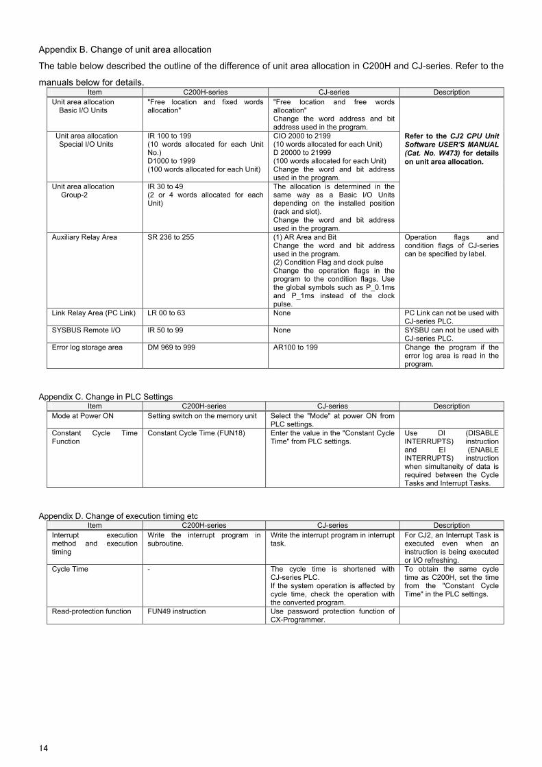
Appendix B. Change of unit area allocation
The table below described the outline of the difference of unit area allocation in C200H and CJ-series. Refer to the
manuals below for details. Item C200H-series CJ-series Description
Unit area allocation Basic I/O Units
"Free location and fixed words allocation"
"Free location and free words allocation" Change the word address and bit address used in the program.
Unit area allocation Special I/O Units
IR 100 to 199 (10 words allocated for each Unit No.) D1000 to 1999 (100 words allocated for each Unit)
CIO 2000 to 2199 (10 words allocated for each Unit) D 20000 to 21999 (100 words allocated for each Unit) Change the word and bit address used in the program.
Refer to the CJ2 CPU Unit Software USER'S MANUAL (Cat. No. W473) for details on unit area allocation.
Unit area allocation Group-2
IR 30 to 49 (2 or 4 words allocated for each Unit)
The allocation is determined in the same way as a Basic I/O Units depending on the installed position (rack and slot). Change the word and bit address used in the program.
Auxiliary Relay Area SR 236 to 255 (1) AR Area and Bit Change the word and bit address used in the program. (2) Condition Flag and clock pulse Change the operation flags in the program to the condition flags. Use the global symbols such as P_0.1ms and P_1ms instead of the clock pulse.
Operation flags and condition flags of CJ-series can be specified by label.
Link Relay Area (PC Link) LR 00 to 63 None PC Link can not be used with CJ-series PLC.
SYSBUS Remote I/O IR 50 to 99 None SYSBU can not be used with CJ-series PLC.
Error log storage area DM 969 to 999 AR100 to 199 Change the program if the error log area is read in the program.
Appendix C. Change in PLC Settings Item C200H-series CJ-series Description
Mode at Power ON Setting switch on the memory unit Select the "Mode" at power ON from PLC settings.
Constant Cycle Time Function
Constant Cycle Time (FUN18) Enter the value in the "Constant Cycle Time" from PLC settings.
Use DI (DISABLE INTERRUPTS) instruction and EI (ENABLE INTERRUPTS) instruction when simultaneity of data is required between the Cycle Tasks and Interrupt Tasks.
Appendix D. Change of execution timing etc Item C200H-series CJ-series Description
Interrupt execution method and execution timing
Write the interrupt program in subroutine.
Write the interrupt program in interrupt task.
For CJ2, an Interrupt Task is executed even when an instruction is being executed or I/O refreshing.
Cycle Time - The cycle time is shortened with CJ-series PLC. If the system operation is affected by cycle time, check the operation with the converted program.
To obtain the same cycle time as C200H, set the time from the "Constant Cycle Time" in the PLC settings.
Read-protection function FUN49 instruction Use password protection function of CX-Programmer.
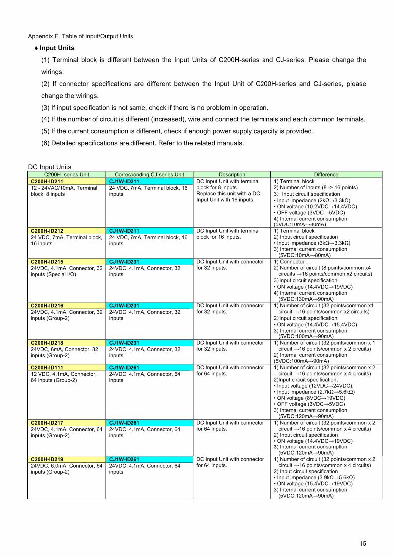
Appendix E. Table of Input/Output Units
Input Units
(1) Terminal block is different between the Input Units of C200H-series and CJ-series. Please change the
wirings.
(2) If connector specifications are different between the Input Unit of C200H-series and CJ-series, please
change the wirings.
(3) If input specification is not same, check if there is no problem in operation.
(4) If the number of circuit is different (increased), wire and connect the terminals and each common terminals.
(5) If the current consumption is different, check if enough power supply capacity is provided.
(6) Detailed specifications are different. Refer to the related manuals.
DC Input Units C200H -series Unit Corresponding CJ-series Unit Description Difference
C200H-ID211 CJ1W-ID211 12 - 24VAC/10mA, Terminal block, 8 inputs
24 VDC, 7mA, Terminal block, 16 inputs
DC Input Unit with terminal block for 8 inputs. Replace this unit with a DC Input Unit with 16 inputs.
1) Terminal block 2) Number of inputs (8 -> 16 points) 3) Input circuit specification • Input impedance (2kΩ→3.3kΩ) • ON voltage (10.2VDC→14.4VDC) • OFF voltage (3VDC→5VDC) 4) Internal current consumption (5VDC:10mA→80mA)
C200H-ID212 CJ1W-ID211 24 VDC, 7mA, Terminal block, 16 inputs
24 VDC, 7mA, Terminal block, 16 inputs
DC Input Unit with terminal block for 16 inputs.
1) Terminal block 2) Input circuit specification • Input impedance (3kΩ→3.3kΩ) 3) Internal current consumption
(5VDC:10mA→80mA) C200H-ID215 CJ1W-ID231 24VDC, 4.1mA, Connector, 32 inputs (Special I/O)
24VDC, 4.1mA, Connector, 32 inputs
DC Input Unit with connector for 32 inputs.
1) Connector 2) Number of circuit (8 points/common x4
circuits →16 points/common x2 circuits) 3)Input circuit specification • ON voltage (14.4VDC→19VDC) 4) Internal current consumption
(5VDC:130mA→90mA) C200H-ID216 CJ1W-ID231 24VDC, 4.1mA, Connector, 32 inputs (Group-2)
24VDC, 4.1mA, Connector, 32 inputs
DC Input Unit with connector for 32 inputs.
1) Number of circuit (32 points/common x1 circuit →16 points/common x2 circuits)
2)Input circuit specification • ON voltage (14.4VDC→15.4VDC) 3) Internal current consumption
(5VDC:100mA→90mA) C200H-ID218 CJ1W-ID231 24VDC, 6mA, Connector, 32 inputs (Group-2)
24VDC, 4.1mA, Connector, 32 inputs
DC Input Unit with connector for 32 inputs.
1) Number of circuit (32 points/common x 1 circuit →16 points/common x 2 circuits)
2) Internal current consumption (5VDC:100mA→90mA)
C200H-ID111 CJ1W-ID261 12 VDC, 4.1mA, Connector, 64 inputs (Group-2)
24VDC, 4.1mA, Connector, 64 inputs
DC Input Unit with connector for 64 inputs.
1) Number of circuit (32 points/common x 2 circuit →16 points/common x 4 circuits)
2)Input circuit specification, • Input voltage (12VDC→24VDC), • Input impedance (2.7kΩ→5.6kΩ) • ON voltage (8VDC→19VDC) • OFF voltage (3VDC→5VDC) 3) Internal current consumption
(5VDC:120mA→90mA) C200H-ID217 CJ1W-ID261 24VDC, 4.1mA, Connector, 64 inputs (Group-2)
24VDC, 4.1mA, Connector, 64 inputs
DC Input Unit with connector for 64 inputs.
1) Number of circuit (32 points/common x 2 circuit →16 points/common x 4 circuits)
2) Input circuit specification • ON voltage (14.4VDC→19VDC) 3) Internal current consumption
(5VDC:120mA→90mA) C200H-ID219 CJ1W-ID261 DC Input Unit with connector
for 64 inputs. 1) Number of circuit (32 points/common x 2
circuit →16 points/common x 4 circuits) 24VDC, 6.0mA, Connector, 64 inputs (Group-2)
24VDC, 4.1mA, Connector, 64 inputs 2) Input circuit specification
• Input impedance (3.9kΩ→5.6kΩ) • ON voltage (15.4VDC→19VDC) 3) Internal current consumption
(5VDC:120mA→90mA)
15
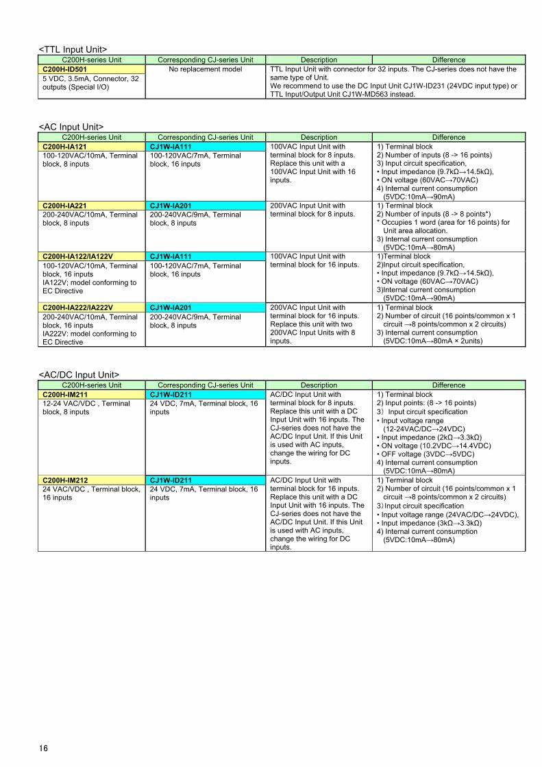
<TTL Input Unit> C200H-series Unit Corresponding CJ-series Unit Description Difference
C200H-ID501 No replacement model TTL Input Unit with connector for 32 inputs. The CJ-series does not have the same type of Unit. 5 VDC, 3.5mA, Connector, 32
outputs (Special I/O) We recommend to use the DC Input Unit CJ1W-ID231 (24VDC input type) or TTL Input/Output Unit CJ1W-MD563 instead.
<AC Input Unit> C200H-series Unit Corresponding CJ-series Unit Description Difference
C200H-IA121 CJ1W-IA111 100-120VAC/10mA, Terminal block, 8 inputs
100-120VAC/7mA, Terminal block, 16 inputs
100VAC Input Unit with terminal block for 8 inputs. Replace this unit with a 100VAC Input Unit with 16 inputs.
1) Terminal block 2) Number of inputs (8 -> 16 points) 3) Input circuit specification, • Input impedance (9.7kΩ→14.5kΩ), • ON voltage (60VAC→70VAC) 4) Internal current consumption
(5VDC:10mA→90mA) C200H-IA221 CJ1W-IA201 200-240VAC/10mA, Terminal block, 8 inputs
200-240VAC/9mA, Terminal block, 8 inputs
200VAC Input Unit with terminal block for 8 inputs.
1) Terminal block 2) Number of inputs (8 -> 8 points*) * Occupies 1 word (area for 16 points) for
Unit area allocation. 3) Internal current consumption
(5VDC:10mA→80mA) C200H-IA122/IA122V CJ1W-IA111 100-120VAC/10mA, Terminal block, 16 inputs IA122V; model conforming to EC Directive
100-120VAC/7mA, Terminal block, 16 inputs
100VAC Input Unit with terminal block for 16 inputs.
1)Terminal block 2)Input circuit specification, • Input impedance (9.7kΩ→14.5kΩ), • ON voltage (60VAC→70VAC) 3)Internal current consumption
(5VDC:10mA→90mA) C200H-IA222/IA222V CJ1W-IA201 200VAC Input Unit with
terminal block for 16 inputs. Replace this unit with two 200VAC Input Units with 8 inputs.
1) Terminal block 2) Number of circuit (16 points/common x 1
circuit →8 points/common x 2 circuits) 200-240VAC/10mA, Terminal block, 16 inputs
200-240VAC/9mA, Terminal block, 8 inputs
IA222V: model conforming to EC Directive
3) Internal current consumption (5VDC:10mA→80mA × 2units)
<AC/DC Input Unit> C200H-series Unit Corresponding CJ-series Unit Description Difference
C200H-IM211 CJ1W-ID211 12-24 VAC/VDC , Terminal block, 8 inputs
24 VDC, 7mA, Terminal block, 16 inputs
AC/DC Input Unit with terminal block for 8 inputs. Replace this unit with a DC Input Unit with 16 inputs. The CJ-series does not have the AC/DC Input Unit. If this Unit is used with AC inputs, change the wiring for DC inputs.
1) Terminal block 2) Input points: (8 -> 16 points) 3) Input circuit specification • Input voltage range
(12-24VAC/DC→24VDC) • Input impedance (2kΩ→3.3kΩ) • ON voltage (10.2VDC→14.4VDC) • OFF voltage (3VDC→5VDC) 4) Internal current consumption
(5VDC:10mA→80mA) C200H-IM212 CJ1W-ID211 AC/DC Input Unit with
terminal block for 16 inputs. Replace this unit with a DC Input Unit with 16 inputs. The CJ-series does not have the AC/DC Input Unit. If this Unit is used with AC inputs, change the wiring for DC inputs.
1) Terminal block 2) Number of circuit (16 points/common x 1
circuit →8 points/common x 2 circuits) 24 VAC/VDC , Terminal block, 16 inputs
24 VDC, 7mA, Terminal block, 16 inputs
3)Input circuit specification • Input voltage range (24VAC/DC→24VDC),• Input impedance (3kΩ→3.3kΩ) 4) Internal current consumption
(5VDC:10mA→80mA)
16
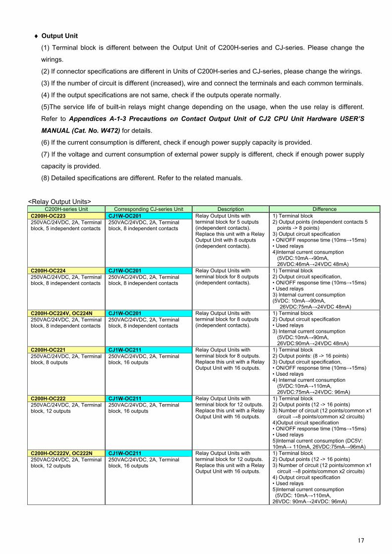
Output Unit
(1) Terminal block is different between the Output Unit of C200H-series and CJ-series. Please change the
wirings.
(2) If connector specifications are different in Units of C200H-series and CJ-series, please change the wirings.
(3) If the number of circuit is different (increased), wire and connect the terminals and each common terminals.
(4) If the output specifications are not same, check if the outputs operate normally.
(5)The service life of built-in relays might change depending on the usage, when the use relay is different.
Refer to Appendices A-1-3 Precautions on Contact Output Unit of CJ2 CPU Unit Hardware USER’S
MANUAL (Cat. No. W472) for details.
(6) If the current consumption is different, check if enough power supply capacity is provided.
(7) If the voltage and current consumption of external power supply is different, check if enough power supply
capacity is provided.
(8) Detailed specifications are different. Refer to the related manuals.
<Relay Output Units> C200H-series Unit Corresponding CJ-series Unit Description Difference
C200H-OC223 CJ1W-OC201 250VAC/24VDC, 2A, Terminal block, 5 independent contacts
250VAC/24VDC, 2A, Terminal block, 8 independent contacts
Relay Output Units with terminal block for 5 outputs (independent contacts). Replace this unit with a Relay Output Unit with 8 outputs (independent contacts).
1) Terminal block 2) Output points (independent contacts 5
points -> 8 points) 3) Output circuit specification • ON/OFF response time (10ms→15ms) • Used relays 4)Internal current consumption
(5VDC:10mA→90mA, 26VDC:46mA→24VDC 48mA)
C200H-OC224 CJ1W-OC201 250VAC/24VDC, 2A, Terminal block, 8 independent contacts
250VAC/24VDC, 2A, Terminal block, 8 independent contacts
Relay Output Units with terminal block for 8 outputs (independent contacts).
1) Terminal block 2) Output circuit specification, • ON/OFF response time (10ms→15ms) • Used relays 3) Internal current consumption (5VDC: 10mA→90mA,
26VDC:75mA→24VDC 48mA) C200H-OC224V, OC224N CJ1W-OC201 250VAC/24VDC, 2A, Terminal block, 8 independent contacts
250VAC/24VDC, 2A, Terminal block, 8 independent contacts
Relay Output Units with terminal block for 8 outputs (independent contacts).
1) Terminal block 2) Output circuit specification • Used relays 3) Internal current consumption
(5VDC:10mA→90mA, 26VDC:90mA→24VDC 48mA)
C200H-OC221 CJ1W-OC211 250VAC/24VDC, 2A, Terminal block, 8 outputs
250VAC/24VDC, 2A, Terminal block, 16 outputs
Relay Output Units with terminal block for 8 outputs. Replace this unit with a Relay Output Unit with 16 outputs.
1) Terminal block 2) Output points: (8 -> 16 points) 3) Output circuit specification, • ON/OFF response time (10ms→15ms) • Used relays 4) Internal current consumption
(5VDC:10mA→110mA, 26VDC:75mA→24VDC: 96mA)
C200H-OC222 CJ1W-OC211 250VAC/24VDC, 2A, Terminal block, 12 outputs
250VAC/24VDC, 2A, Terminal block, 16 outputs
Relay Output Units with terminal block for 12 outputs. Replace this unit with a Relay Output Unit with 16 outputs.
1) Terminal block 2) Output points (12 -> 16 points) 3) Number of circuit (12 points/common x1
circuit →8 points/common x2 circuits) 4)Output circuit specification • ON/OFF response time (10ms→15ms) • Used relays 5)Internal current consumption (DC5V: 10mA→ 110mA, 26VDC:75mA→96mA)
C200H-OC222V, OC222N CJ1W-OC211 Relay Output Units with terminal block for 12 outputs. Replace this unit with a Relay Output Unit with 16 outputs.
1) Terminal block 2) Output points (12 -> 16 points) 3) Number of circuit (12 points/common x1
circuit →8 points/common x2 circuits)
250VAC/24VDC, 2A, Terminal block, 12 outputs
250VAC/24VDC, 2A, Terminal block, 16 outputs
4) Output circuit specification • Used relays 5)Internal current consumption (5VDC: 10mA→110mA, 26VDC: 90mA→24VDC: 96mA)
17
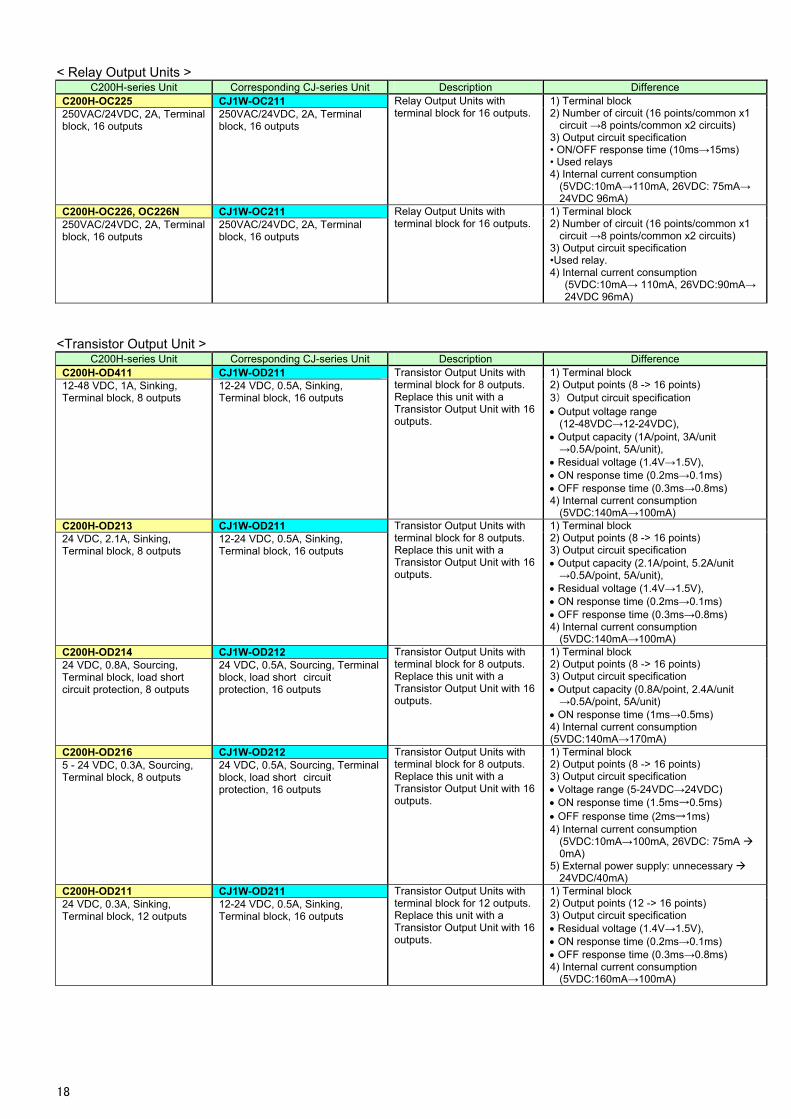
< Relay Output Units > C200H-series Unit Corresponding CJ-series Unit Description Difference
C200H-OC225 CJ1W-OC211 250VAC/24VDC, 2A, Terminal block, 16 outputs
250VAC/24VDC, 2A, Terminal block, 16 outputs
Relay Output Units with terminal block for 16 outputs.
1) Terminal block 2) Number of circuit (16 points/common x1
circuit →8 points/common x2 circuits) 3) Output circuit specification • ON/OFF response time (10ms→15ms) • Used relays 4) Internal current consumption
(5VDC:10mA→110mA, 26VDC: 75mA→ 24VDC 96mA)
C200H-OC226, OC226N CJ1W-OC211 Relay Output Units with terminal block for 16 outputs.
1) Terminal block 2) Number of circuit (16 points/common x1
circuit →8 points/common x2 circuits) 3) Output circuit specification
250VAC/24VDC, 2A, Terminal block, 16 outputs
250VAC/24VDC, 2A, Terminal block, 16 outputs
•Used relay. 4) Internal current consumption
(5VDC:10mA→ 110mA, 26VDC:90mA→ 24VDC 96mA)
<Transistor Output Unit > C200H-series Unit Corresponding CJ-series Unit Description Difference
C200H-OD411 CJ1W-OD211 12-48 VDC, 1A, Sinking, Terminal block, 8 outputs
12-24 VDC, 0.5A, Sinking, Terminal block, 16 outputs
Transistor Output Units with terminal block for 8 outputs. Replace this unit with a Transistor Output Unit with 16 outputs.
1) Terminal block 2) Output points (8 -> 16 points) 3) Output circuit specification Output voltage range
(12-48VDC→12-24VDC), Output capacity (1A/point, 3A/unit →0.5A/point, 5A/unit),
Residual voltage (1.4V→1.5V), ON response time (0.2ms→0.1ms) OFF response time (0.3ms→0.8ms) 4) Internal current consumption
(5VDC:140mA→100mA) C200H-OD213 CJ1W-OD211 24 VDC, 2.1A, Sinking, Terminal block, 8 outputs
12-24 VDC, 0.5A, Sinking, Terminal block, 16 outputs
Transistor Output Units with terminal block for 8 outputs. Replace this unit with a Transistor Output Unit with 16 outputs.
1) Terminal block 2) Output points (8 -> 16 points) 3) Output circuit specification Output capacity (2.1A/point, 5.2A/unit →0.5A/point, 5A/unit),
Residual voltage (1.4V→1.5V), ON response time (0.2ms→0.1ms) OFF response time (0.3ms→0.8ms) 4) Internal current consumption
(5VDC:140mA→100mA) C200H-OD214 CJ1W-OD212 24 VDC, 0.8A, Sourcing, Terminal block, load short circuit protection, 8 outputs
24 VDC, 0.5A, Sourcing, Terminal block, load short circuit protection, 16 outputs
Transistor Output Units with terminal block for 8 outputs. Replace this unit with a Transistor Output Unit with 16 outputs.
1) Terminal block 2) Output points (8 -> 16 points) 3) Output circuit specification Output capacity (0.8A/point, 2.4A/unit →0.5A/point, 5A/unit)
ON response time (1ms→0.5ms) 4) Internal current consumption (5VDC:140mA→170mA)
C200H-OD216 CJ1W-OD212 5 - 24 VDC, 0.3A, Sourcing, Terminal block, 8 outputs
24 VDC, 0.5A, Sourcing, Terminal block, load short circuit protection, 16 outputs
Transistor Output Units with terminal block for 8 outputs. Replace this unit with a Transistor Output Unit with 16 outputs.
1) Terminal block 2) Output points (8 -> 16 points) 3) Output circuit specification Voltage range (5-24VDC→24VDC) ON response time (1.5ms→0.5ms) OFF response time (2ms→1ms) 4) Internal current consumption
(5VDC:10mA→100mA, 26VDC: 75mA 0mA)
5) External power supply: unnecessary 24VDC/40mA)
C200H-OD211 CJ1W-OD211 Transistor Output Units with terminal block for 12 outputs. Replace this unit with a Transistor Output Unit with 16 outputs.
1) Terminal block 2) Output points (12 -> 16 points) 24 VDC, 0.3A, Sinking,
Terminal block, 12 outputs 12-24 VDC, 0.5A, Sinking, Terminal block, 16 outputs 3) Output circuit specification
Residual voltage (1.4V→1.5V), ON response time (0.2ms→0.1ms) OFF response time (0.3ms→0.8ms) 4) Internal current consumption
(5VDC:160mA→100mA)
18
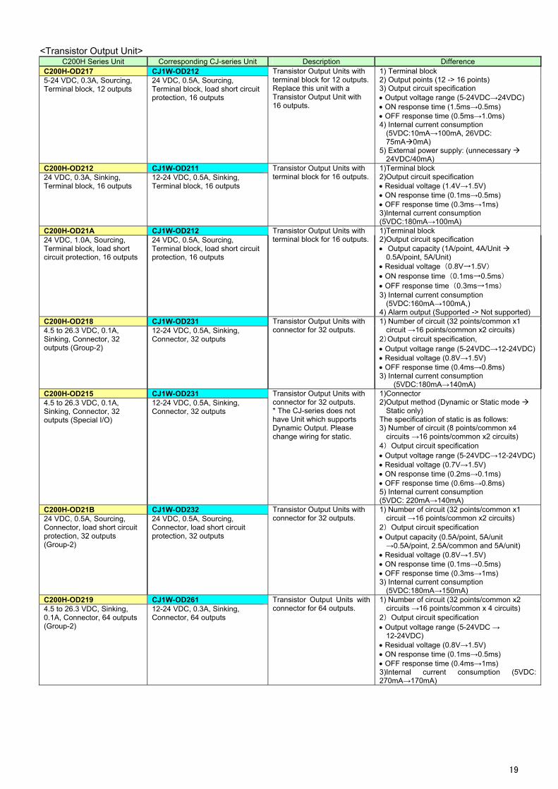
<Transistor Output Unit> C200H Series Unit Corresponding CJ-series Unit Description Difference
C200H-OD217 CJ1W-OD212 5-24 VDC, 0.3A, Sourcing, Terminal block, 12 outputs
24 VDC, 0.5A, Sourcing, Terminal block, load short circuit protection, 16 outputs
Transistor Output Units with terminal block for 12 outputs. Replace this unit with a Transistor Output Unit with 16 outputs.
1) Terminal block 2) Output points (12 -> 16 points) 3) Output circuit specification Output voltage range (5-24VDC→24VDC) ON response time (1.5ms→0.5ms) OFF response time (0.5ms→1.0ms) 4) Internal current consumption
(5VDC:10mA→100mA, 26VDC: 75mA0mA)
5) External power supply: (unnecessary 24VDC/40mA)
C200H-OD212 CJ1W-OD211 24 VDC, 0.3A, Sinking, Terminal block, 16 outputs
12-24 VDC, 0.5A, Sinking, Terminal block, 16 outputs
Transistor Output Units with terminal block for 16 outputs.
1)Terminal block 2)Output circuit specification Residual voltage (1.4V→1.5V) ON response time (0.1ms→0.5ms) OFF response time (0.3ms→1ms) 3)Internal current consumption (5VDC:180mA→100mA)
C200H-OD21A CJ1W-OD212 24 VDC, 1.0A, Sourcing, Terminal block, load short circuit protection, 16 outputs
24 VDC, 0.5A, Sourcing, Terminal block, load short circuit protection, 16 outputs
Transistor Output Units with terminal block for 16 outputs.
1)Terminal block 2)Output circuit specification Output capacity (1A/point, 4A/Unit
0.5A/point, 5A/Unit) Residual voltage (0.8V→1.5V) ON response time (0.1ms→0.5ms) OFF response time (0.3ms→1ms) 3) Internal current consumption
(5VDC:160mA→100mA,) 4) Alarm output (Supported -> Not supported)
C200H-OD218 CJ1W-OD231 4.5 to 26.3 VDC, 0.1A, Sinking, Connector, 32 outputs (Group-2)
12-24 VDC, 0.5A, Sinking, Connector, 32 outputs
Transistor Output Units with connector for 32 outputs.
1) Number of circuit (32 points/common x1 circuit →16 points/common x2 circuits)
2)Output circuit specification, Output voltage range (5-24VDC→12-24VDC) Residual voltage (0.8V→1.5V) OFF response time (0.4ms→0.8ms) 3) Internal current consumption
(5VDC:180mA→140mA) C200H-OD215 CJ1W-OD231 4.5 to 26.3 VDC, 0.1A, Sinking, Connector, 32 outputs (Special I/O)
12-24 VDC, 0.5A, Sinking, Connector, 32 outputs
Transistor Output Units with connector for 32 outputs. * The CJ-series does not have Unit which supports Dynamic Output. Please change wiring for static.
1)Connector 2)Output method (Dynamic or Static mode
Static only) The specification of static is as follows: 3) Number of circuit (8 points/common x4
circuits →16 points/common x2 circuits) 4) Output circuit specification Output voltage range (5-24VDC→12-24VDC) Residual voltage (0.7V→1.5V) ON response time (0.2ms→0.1ms) OFF response time (0.6ms→0.8ms) 5) Internal current consumption (5VDC: 220mA→140mA)
C200H-OD21B CJ1W-OD232 24 VDC, 0.5A, Sourcing, Connector, load short circuit protection, 32 outputs (Group-2)
24 VDC, 0.5A, Sourcing, Connector, load short circuit protection, 32 outputs
Transistor Output Units with connector for 32 outputs.
1) Number of circuit (32 points/common x1 circuit →16 points/common x2 circuits)
2) Output circuit specification Output capacity (0.5A/point, 5A/unit →0.5A/point, 2.5A/common and 5A/unit)
Residual voltage (0.8V→1.5V) ON response time (0.1ms→0.5ms) OFF response time (0.3ms→1ms) 3) Internal current consumption
(5VDC:180mA→150mA) C200H-OD219 CJ1W-OD261 Transistor Output Units with
connector for 64 outputs. 1) Number of circuit (32 points/common x2
circuits →16 points/common x 4 circuits) 2) Output circuit specification
4.5 to 26.3 VDC, Sinking, 0.1A, Connector, 64 outputs (Group-2)
12-24 VDC, 0.3A, Sinking, Connector, 64 outputs
Output voltage range (5-24VDC → 12-24VDC)
Residual voltage (0.8V→1.5V) ON response time (0.1ms→0.5ms) OFF response time (0.4ms→1ms) 3)Internal current consumption (5VDC: 270mA→170mA)
19
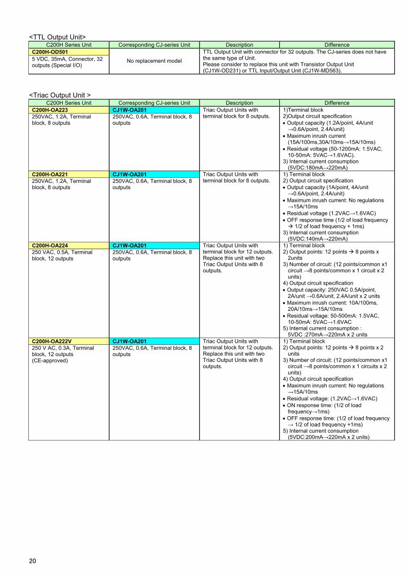
<TTL Output Unit> C200H Series Unit Corresponding CJ-series Unit Description Difference
C200H-OD501 TTL Output Unit with connector for 32 outputs. The CJ-series does not have the same type of Unit. 5 VDC, 35mA, Connector, 32
outputs (Special I/O) No replacement model
Please consider to replace this unit with Transistor Output Unit (CJ1W-OD231) or TTL Input/Output Unit (CJ1W-MD563).
<Triac Output Unit > C200H Series Unit Corresponding CJ-series Unit Description Difference
C200H-OA223 CJ1W-OA201 250VAC, 1.2A, Terminal block, 8 outputs
250VAC, 0.6A, Terminal block, 8 outputs
Triac Output Units with terminal block for 8 outputs.
1)Terminal block 2)Output circuit specification Output capacity (1.2A/point, 4A/unit →0.6A/point, 2.4A/unit)
Maximum inrush current (15A/100ms,30A/10ms→15A/10ms)
Residual voltage (50-1200mA: 1.5VAC, 10-50mA: 5VAC→1.6VAC).
3) Internal current consumption (5VDC:180mA→220mA)
C200H-OA221 CJ1W-OA201 250VAC, 1.2A, Terminal block, 8 outputs
250VAC, 0.6A, Terminal block, 8 outputs
Triac Output Units with terminal block for 8 outputs.
1) Terminal block 2) Output circuit specification Output capacity (1A/point, 4A/unit →0.6A/point, 2.4A/unit)
Maximum inrush current: No regulations →15A/10ms
Residual voltage (1.2VAC→1.6VAC) OFF response time (1/2 of load frequency 1/2 of load frequency + 1ms)
3) Internal current consumption (5VDC:140mA→220mA)
C200H-OA224 CJ1W-OA201 250 VAC, 0.5A, Terminal block, 12 outputs
250VAC, 0.6A, Terminal block, 8 outputs
Triac Output Units with terminal block for 12 outputs. Replace this unit with two Triac Output Units with 8 outputs.
1) Terminal block 2) Output points: 12 points 8 points x
2units 3) Number of circuit: (12 points/common x1
circuit →8 points/common x 1 circuit x 2 units)
4) Output circuit specification Output capacity: 250VAC 0.5A/point,
2A/unit →0.6A/unit, 2.4A/unit x 2 units Maximum inrush current: 10A/100ms,
20A/10ms→15A/10ms Residual voltage: 50-500mA: 1.5VAC,
10-50mA: 5VAC→1.6VAC 5) Internal current consumption :
5VDC :270mA→220mA x 2 units C200H-OA222V CJ1W-OA201 Triac Output Units with
terminal block for 12 outputs. Replace this unit with two Triac Output Units with 8 outputs.
1) Terminal block 2) Output points: 12 points 8 points x 2
units 3) Number of circuit: (12 points/common x1
circuit →8 points/common x 1 circuits x 2 units)
4) Output circuit specification
250 V AC, 0.3A, Terminal block, 12 outputs (CE-approved)
250VAC, 0.6A, Terminal block, 8 outputs
Maximum inrush current: No regulations →15A/10ms
Residual voltage: (1.2VAC→1.6VAC) ON response time: (1/2 of load
frequency→1ms) OFF response time: (1/2 of load frequency → 1/2 of load frequency +1ms)
5) Internal current consumption (5VDC:200mA→220mA x 2 units)
20
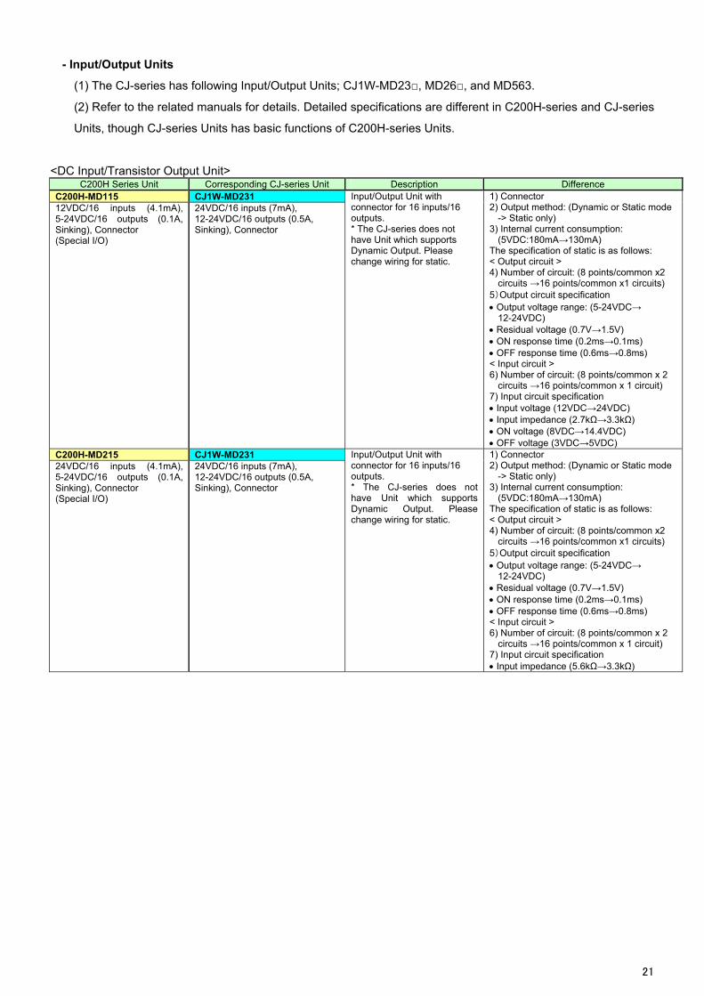
- Input/Output Units
(1) The CJ-series has following Input/Output Units; CJ1W-MD23, MD26, and MD563.
(2) Refer to the related manuals for details. Detailed specifications are different in C200H-series and CJ-series
Units, though CJ-series Units has basic functions of C200H-series Units.
<DC Input/Transistor Output Unit> C200H Series Unit Corresponding CJ-series Unit Description Difference
C200H-MD115 CJ1W-MD231 12VDC/16 inputs (4.1mA), 5-24VDC/16 outputs (0.1A, Sinking), Connector (Special I/O)
24VDC/16 inputs (7mA), 12-24VDC/16 outputs (0.5A, Sinking), Connector
Input/Output Unit with connector for 16 inputs/16 outputs. * The CJ-series does not have Unit which supports Dynamic Output. Please change wiring for static.
1) Connector 2) Output method: (Dynamic or Static mode
-> Static only) 3) Internal current consumption:
(5VDC:180mA→130mA) The specification of static is as follows: < Output circuit > 4) Number of circuit: (8 points/common x2
circuits →16 points/common x1 circuits) 5)Output circuit specification Output voltage range: (5-24VDC→
12-24VDC) Residual voltage (0.7V→1.5V) ON response time (0.2ms→0.1ms) OFF response time (0.6ms→0.8ms) < Input circuit > 6) Number of circuit: (8 points/common x 2
circuits →16 points/common x 1 circuit) 7) Input circuit specification Input voltage (12VDC→24VDC) Input impedance (2.7kΩ→3.3kΩ) ON voltage (8VDC→14.4VDC) OFF voltage (3VDC→5VDC)
C200H-MD215 CJ1W-MD231 Input/Output Unit with connector for 16 inputs/16 outputs. * The CJ-series does not have Unit which supports Dynamic Output. Please change wiring for static.
1) Connector 2) Output method: (Dynamic or Static mode
-> Static only) 3) Internal current consumption:
(5VDC:180mA→130mA) The specification of static is as follows: < Output circuit > 4) Number of circuit: (8 points/common x2
circuits →16 points/common x1 circuits) 5)Output circuit specification Output voltage range: (5-24VDC→
12-24VDC) Residual voltage (0.7V→1.5V) ON response time (0.2ms→0.1ms)
24VDC/16 inputs (4.1mA), 5-24VDC/16 outputs (0.1A, Sinking), Connector
24VDC/16 inputs (7mA), 12-24VDC/16 outputs (0.5A, Sinking), Connector
(Special I/O)
OFF response time (0.6ms→0.8ms) < Input circuit > 6) Number of circuit: (8 points/common x 2
circuits →16 points/common x 1 circuit) 7) Input circuit specification Input impedance (5.6kΩ→3.3kΩ)
21
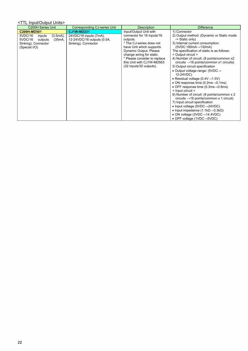
<TTL Input/Output Units> C200H Series Unit Corresponding CJ-series Unit Description Difference
C200H-MD501 CJ1W-MD231 Input/Output Unit with connector for 16 inputs/16 outputs. * The CJ-series does not have Unit which supports Dynamic Output. Please change wiring for static. * Please consider to replace this Unit with CJ1W-MD563 (32 inputs/32 outputs).
1) Connector 2) Output method: (Dynamic or Static mode
-> Static only) 3) Internal current consumption:
(5VDC:180mA→130mA) The specification of static is as follows: < Output circuit > 4) Number of circuit: (8 points/common x2
circuits →16 points/common x1 circuits) 5)Output circuit specification Output voltage range: (5VDC→
12-24VDC) Residual voltage (0.4V→1.5V) ON response time (0.2ms→0.1ms) OFF response time (0.3ms→0.8ms) < Input circuit > 6) Number of circuit: (8 points/common x 2
circuits →16 points/common x 1 circuit)
5VDC/16 inputs (3.5mA), 5VDC/16 outputs (35mA, Sinking), Connector
24VDC/16 inputs (7mA), 12-24VDC/16 outputs (0.5A, Sinking), Connector
(Special I/O)
7) Input circuit specification Input voltage (5VDC→24VDC) Input impedance (1.1kΩ→3.3kΩ) ON voltage (3VDC→14.4VDC) OFF voltage (1VDC→5VDC)
22
OMRON CANADA, INC. • HEAD OFFICEToronto, ON, Canada • 416.286.6465 • 866.986.6766 • www.omron247.com
OMRON ELECTRONICS DE MEXICO • HEAD OFFICEMéxico DF • 52.55.59.01.43.00 • 001.800.556.6766 • [email protected]
OMRON ELECTRONICS DE MEXICO • SALES OFFICEApodaca, N.L. • 52.81.11.56.99.20 • 001.800.556.6766 • [email protected]
OMRON ELETRÔNICA DO BRASIL LTDA • HEAD OFFICESão Paulo, SP, Brasil • 55.11.2101.6300 • www.omron.com.br
OMRON ARGENTINA • SALES OFFICECono Sur • 54.11.4783.5300
OMRON CHILE • SALES OFFICESantiago • 56.9.9917.3920
OTHER OMRON LATIN AMERICA SALES54.11.4783.5300
OMRON INDUSTRIAL AUTOMATION • THE AMERICAS HEADQUARTERSSchaumburg, IL USA • 847.843.7900 • 800.556.6766 • www.omron247.com
OMRON EUROpE B.V. • Wegalaan 67-69, NL-2132 JD, Hoofddorp, The Netherlands. • Tel: +31 (0) 23 568 13 00Fax: +31 (0) 23 568 13 88 • www.industrial.omron.eu
Cat. No. P073-E1-01 06/11 Note: Specifications are subject to change. © 2012 Omron Electronics LLC Printed in U.S.A.