c01 revit st 2014 eval
TRANSCRIPT

Chapter 1
Introduction to Autodesk Revit Structure 2014
After completing this chapter, you will be able to:• Understand the basic concepts and principles of Revit Structure 2014• Understand various terms used in Revit Structure• Describe the parametric behavior of Revit Structure• Start the Revit Structure 2014 program• Understand the linking of Analytical Model to Analysis Software• Understand the interface of Revit Structure• Explain the concept of Worksharing using Revit Server• Access the Revit Structure 2014 Help
Learning Objectives

1-2 Exploring Autodesk Revit StructureEva
lua
tion
Cop
y. D
o no
t re
prod
uce.
For
inf
orm
ati
on v
isit
ww
w.c
adc
im.c
om
introduction to Autodesk revit StructureWelcome to the realm of Autodesk Revit Structure, a powerful software for structural engineering that provides purpose-built tools for structural design, engineering, and analysis.
Autodesk Revit Structure is specifically built for Structural Engineers and Designers. This software provides the Engineers and Designers with tools for structural analysis and design. Revit Structure is a BIM software that helps the users in a project to coordinate the documentation of structural design with other disciplines of engineering. Its integrated parametric modeling technology is used to create the information model of a project and to collect and coordinate information across all its representations. In Autodesk Revit Structure, drawing sheets, 2D views, 3D views, and schedules directly represent the same building information model (BIM). In this software, the physical model is associated with an analytical model. As a result, the model created in Revit Structure is ready to be analyzed in a compatible structural analysis software, such as Autodesk Robot Structural Analysis. Using its parametric change engine, you can modify a design at any stage of its creation. The change in the project is automatically made and represented in all its views, resulting in the development of better designs, along with an improved coordination. The use of Autodesk Revit Structure provides a competitive advantage and a higher profitability to structural engineers and building industry professionals.
Autodesk revit Structure AS A building informAtion modelerThe history of computer aided design and documentation dates back to the early 1980s when architects and engineers began using this technology for documenting their projects. Realizing its advantages, information sharing capabilities were developed, especially to share data with other consultants. This led to the development of object-based CAD systems in the early 1990s. Before the development of these systems, objects such as structural walls, beams, columns, and slabs were stored as a non-graphical data with the assigned graphics. These systems arranged the information logically but were unable to optimize its usage in a building project. Realizing the advantages of the solid modeling tools, the mechanical and manufacturing industry professionals began using the information modeling CAD technology. This technology enabled them to extract data based on the relationship between model elements.
In 1997, a group of mechanical CAD technologists began working on a new software for the building industry. The Building Information Modeling (BIM) provided an alternative approach to building design, construction, and management. This approach, however, required a suitable technology to implement so as to reap its benefits. In such a situation, the use of parametric technology with the Building Information Modeling approach was envisaged as an ideal combination. They developed a software that was suitable for creating building projects. This led to the development of Autodesk Revit Structure.
Autodesk Revit Structure is a structural design and documentation platform, in which a digital structural model is created using the parametric elements such as structural walls, beams, columns and so on. All building elements have inherent relationship with one another, which can be tracked, managed, and maintained by the computer.

Introduction to Autodesk Revit Structure 2014 1-3
Eva
lua
tion
Cop
y. D
o no
t re
prod
uce.
For
inf
orm
ati
on v
isit
ww
w.c
adc
im.c
om
bASic conceptS And principleS Autodesk Revit Structure enables you to envisage and develop a structural model with actual 3D parametric structural elements. It provides a new approach to the structural design and the implementation process. It replicates the way structural engineers conceive the structure of a building. For example, the 2D CAD platforms mostly use lines to represent all elements, as shown in Figure 1-1. However, in Autodesk Revit Structure, you can create the structural model of a building project using 3D elements, such as structural walls, structural floors, columns, and beams, as shown in Figure 1-2.
Figure 1-2 A structural project created using parametric structural elements
Figure 1-1 CAD project created using 2D lines

1-4 Exploring Autodesk Revit StructureEva
lua
tion
Cop
y. D
o no
t re
prod
uce.
For
inf
orm
ati
on v
isit
ww
w.c
adc
im.c
om
Using these 3D elements, you can visualize the structural project with respect to its scale, volume, and proportions. This enables you to study design alternatives and develop superior quality design solutions. Autodesk Revit Structure automates routine drafting and coordination tasks and assists in reducing errors in documentation. This, in turn, saves time, improves the speed of documentation, and lowers the cost for users.
understanding the parametric building modeling technologyA project in Autodesk Revit Structure is created using the inbuilt parametric building elements. The term ‘parametric’ refers to the parameters that relate various building elements. Some relationships are made by Autodesk Revit Structure itself and others by the user. For example, doors, which have an inherent parametric relationship with structural walls, cannot be created without first creating a host wall. A door always moves with the host wall. Similarly, floors too are parametrically linked to walls. When you move structural walls, the structural floor extents are also modified automatically. Each structural element has inbuilt bidirectional associativity with many other elements in the project.
A building information model is created using different interdependent parametric building elements such as structural walls, beams, columns, structural floors, foundations, and so on. As they are bidirectionally associated elements, any change made in one element is automatically adopted by others. The integrated building information model thus created contains all data for a project. You can then create project presentation views such as structural plans, sections, elevations, and so on for documentation. As you modify the model while working in certain views, Autodesk Revit Structure’s parametric change engine automatically updates other views. This capability is, therefore, the underlying concept in Autodesk Revit Structure.
Autodesk Revit Structure’s parametric change engine enables you to modify design elements at any stage of the project development. As changes are made immediately and automatically, it saves the time and effort of coordinating them in all other associated views, which, for most projects, is an inevitable part of the design process. Autodesk Revit Structure’s capability to coordinate between various aspects of the building design provides immense flexibility in the design and development process along with an error-free documentation.
Autodesk Revit Structure also provides a variety of in-built parametric element libraries that can be selected and used to create a building model. It also provides you with the flexibility to modify the properties of these elements or to create your own parametric elements, based on the project requirement.
terms used in Autodesk revit StructureBefore using Autodesk Revit Structure, it is important to understand the basic terms used for creating a building model. Various terms in Autodesk Revit Structure such as project, level, category, family, type, and instance are described next.
Autodesk revit Structure projectA project in Autodesk Revit Structure is similar to an actual structural project. In an actual project, the entire documentation such as drawings, 3D views, specifications, schedules, cost estimates, and so on are inherently linked and read together. Similarly, in Autodesk Revit

Introduction to Autodesk Revit Structure 2014 1-5
Eva
lua
tion
Cop
y. D
o no
t re
prod
uce.
For
inf
orm
ati
on v
isit
ww
w.c
adc
im.c
om
Structure, a project not only includes the digital 3D building model but also its parametrically associated documentation. Thus, all components such as the building model, its standard views, structural drawings, and schedules combine together to form a complete project. A project file contains all project information such as building elements used in a project, drawing sheets, schedules, cost estimates, 3D views, renderings, and so on. A project file also stores various settings such as environment, lighting, and so on. As data is stored in the same file, so it becomes easier for Autodesk Revit Structure to coordinate the entire database.
levels in a building modelIn Autodesk Revit Structure, a building model is divided into different levels. These levels may be understood as infinite horizontal planes that act as hosts for different elements such as roof, floor, ceiling, and so on. The defined levels in a building model can, in most cases, relate to different floor levels, or stories of the building project. Each element that you create belongs to a particular level.
Subdivisions of elements into categories and SubcategoriesApart from building elements, a Autodesk Revit Structure project also contains other associated elements such as annotations, imported files, links, and so on. These elements have been divided into the following categories:
Model Category : Consists of various structural elements used in creating a building model such as structural walls, structural floors, foundations, beams, braces, and columns.
Annotation Category : Consists of annotations such as dimensions, text notes, tags, symbols, and so on
Datum Category : Consists of datums such as levels, grids, reference planes, and so on
View Category : Consists of interactive project views such a structural floor plans, elevations, sections, 3D views, and renderings
In addition to these four categories, other categories such as Imported, Workset, Filter, and Revit Categories can also exist, if the project has imported files, enabled worksets, or linked Autodesk Revit Structure projects, respectively.
families in Autodesk revit StructureAnother powerful concept in Autodesk Revit Structure is family. A family is described as a set of elements of the same category that can be grouped together based on certain common parameters or characteristics. Elements of the same family may have different properties, but they all have common characteristics. For example, W-Wide Flange-Column is a flange column family, but it contains different sizes of flange columns. Family files have the .rfa extension. You can load additional building component families from the libraries provided in Autodesk Revit Structure package.
1-6 Exploring Autodesk Revit StructureEva
lua
tion
Cop
y. D
o no
t re
prod
uce.
For
inf
orm
ati
on v
isit
ww
w.c
adc
im.c
om
Families are further divided into certain types. Type or family type, as it is called, is a specific size or style of a family. For example, W-Wide-Flange-Column : W10X49 is a column type. All uses of the same family type in a project have the same properties. Family and family types can also be used to create new families using the Family Editor.
Instances are the actual usage of model elements in a building model or annotations in a drawing sheet. A family type, created in a new location, is identified as an instance of the family type. All instances of the same family type have the same properties. Therefore, when you modify the properties of a family type, the properties of all its instances also get modified. The family categorization of Revit elements is given below:
Model Category : BeamFamily : W-Wide FlangeFamily type : W12x26Instance : Particular usage of a family type
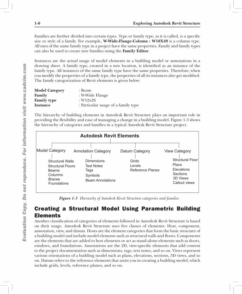
The hierarchy of building elements in Autodesk Revit Structure plays an important role in providing the flexibility and ease of managing a change in a building model. Figure 1-3 shows the hierarchy of categories and families in a typical Autodesk Revit Structure project.
Figure 1-3 Hierarchy of Autodesk Revit Structure categories and families
Autodesk Revit Elements
Model Category Annotation Category Datum Category View Category
Structural WallsStructural FloorsBeamsColumnsBracesFoundations
DimensionsText NotesTagsSymbolsBeam Annotations
GridsLevelsReference Planes
Structural FloorPlansElevationsSections3D ViewsCallout views
creating a Structural model using parametric building elementsAnother classification of categories of elements followed in Autodesk Revit Structure is based on their usage. Autodesk Revit Structure uses five classes of elements: Host, component, annotation, view, and datum. Hosts are the element categories that form the basic structure of a building model and include model elements such as structural walls and floors. Components are the elements that are added to host elements or act as stand-alone elements such as doors, windows, and foundations. Annotations are the 2D, view-specific elements that add content to the project documentation such as dimensions, tags, text notes, and so on. Views represent various orientations of a building model such as plans, elevations, sections, 3D views, and so on. Datum refers to the reference elements that assist you in creating a building model, which include grids, levels, reference planes, and so on.
Introduction to Autodesk Revit Structure 2014 1-7
Eva
lua
tion
Cop
y. D
o no
t re
prod
uce.
For
inf
orm
ati
on v
isit
ww
w.c
adc
im.c
om
There is no specific methodology available for creating a building model in Autodesk Revit Structure. It provides you with the flexibility of generating the building geometry based on the project requirement, design complexity, and other factors. However, the following steps describe a general procedure that may be followed for creating an architectural building model using the built-in parametric elements provided in Autodesk Revit Structure.
The first step is to define the levels of the structural model based on the story height of the building and then create grids for inserting columns and foundation at the lowest level. Next, add columns, foundation slab, structural wall, and foundations in that level. You can also link the control height of the structural walls and columns to the levels. Next, create framing members and floors using the defined levels. You can add loads, define load conditions, and various analytical settings to the model.
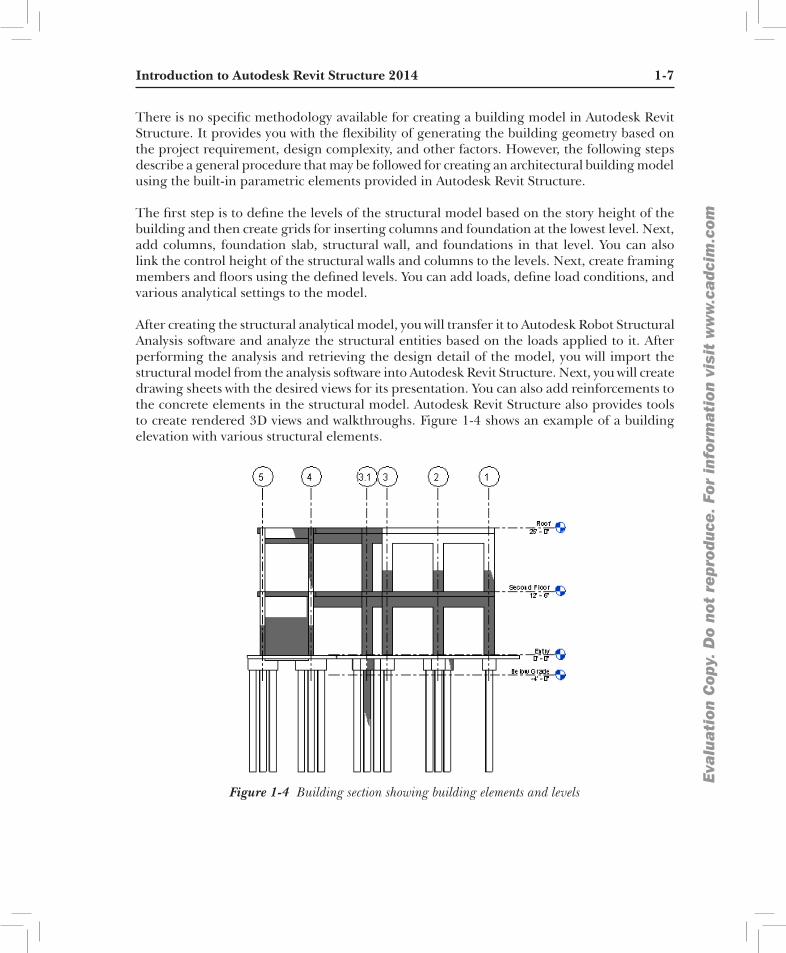
After creating the structural analytical model, you will transfer it to Autodesk Robot Structural Analysis software and analyze the structural entities based on the loads applied to it. After performing the analysis and retrieving the design detail of the model, you will import the structural model from the analysis software into Autodesk Revit Structure. Next, you will create drawing sheets with the desired views for its presentation. You can also add reinforcements to the concrete elements in the structural model. Autodesk Revit Structure also provides tools to create rendered 3D views and walkthroughs. Figure 1-4 shows an example of a building elevation with various structural elements.
Figure 1-4 Building section showing building elements and levels

1-8 Exploring Autodesk Revit StructureEva
lua
tion
Cop
y. D
o no
t re
prod
uce.
For
inf
orm
ati
on v
isit
ww
w.c
adc
im.c
om
Visibility/graphics overrides, Scale, and detail level Autodesk Revit Structure enables you to control the display and graphic representation of a single element or the element category of various elements in project views by using the visibility and graphics overrides tools. You can select a model category and modify its linetype and detail level. This can also be done for various annotation category elements and imported files. These settings can be done for each project view based on its desired representation. You can also hide an element or an element category in a view using the Hide in view and Isolate tools. You can override the graphic representation of an element or an element category in any view using the Visibility/Graphics tool.
The scale is another important concept in an Autodesk Revit Structure project. You can set the scale for each project view by selecting it from the available list of standard scales such as 1/16”=1’0”, 1/4”=1’0”, 1”=1’0”, 1/2”=1’0”, and so on. As you set a scale, Autodesk Revit Structure automatically sets the detail level that is appropriate for it. There are three detail levels provided in an Autodesk Revit Structure project: Coarse, Medium, and Fine. You can also set the detail level manually for each project view. Each detail level has an associated linetype and the detail lines associated with it. The details of annotations, such as dimensions, tags, and so on, are also defined by the selected scale.
extracting project informationA single integrated building information is used to create and represent a building project. You can extract project information from a building model and create area schemes, schedule, and cost estimates, and then add them to the project presentation.
Autodesk Revit Structure also enables you to export the extracted database to the industry standard Open Database Connectivity (ODBC) compliant relational database tables. The use of the building information model to extract database information eliminates the error-prone method of measuring building spaces individually.
creating a Structural drawing SetAfter creating the building model, you can easily arrange the project views by plotting them on drawing sheets. Drawing sheets can also be organized in a project file based on the established CAD standards followed by the firm. In this manner, the project documentation can easily be transformed from the conceptual design stage to the design development stage and finally to the construction document stage. The project view on a drawing sheet is only a graphical representation of the building information model. Therefore, any modification in it is immediately made in all associated project views, keeping the drawings set always updated.
creating an unusual building geometryAutodesk Revit Structure also helps you conceptualize a building project in terms of its volume, shape, and proportions before working with actual building elements. This is possible by using the Massing tool, which enables you to create quick 3D models of buildings and conduct volumetric and proportion study on overall masses. It also enables you to visualize and create an unusual building geometry. The same massing model can then be converted into a building model with individual parametric building elements. It provides continuity in the generation of building model right from sketch design to its development.

Introduction to Autodesk Revit Structure 2014 1-9
Eva
lua
tion
Cop
y. D
o no
t re
prod
uce.
For
inf
orm
ati
on v
isit
ww
w.c
adc
im.c
om
flexibility of creating Special elementsAutodesk Revit Structure provides a large number of in-built family types of various model elements and annotations. Each parametric element has the associated properties that can be modified based on the project requirement.
Autodesk Revit Structure also enables you to create the elements that are designed specifically for a particular location. The in-built family editor enables you to create new elements using family templates. This provides you with the flexibility of using in-built elements for creating your own elements. For example, using the furniture template, you can create a reception desk that is suitable for a particular location in the design.
creating Structural layoutsAutodesk Revit Structure’s structural tools enable you to add structural elements to a building model. An extensive in-built library of structural elements has been provided in Autodesk Revit Structure. You can add structural columns, beams, walls, braces, and so on to the project. Thus, structural consultants can also incorporate their elements in the basic architectural building model and check for inconsistency, if any.
Working on large projectsIn Autodesk Revit Structure, you can work on large projects by linking different building projects together. For a large project that consists of a number of buildings, you can create individual buildings as separate projects and then link all of them into a single base file. The database recognizes the linked projects and includes them in the project representation of the base file.
For example, while working on a large educational institution campus, you can create separate project files for academic building, administration area, gymnasium, cafeteria, computer centre, and so on, and then link them into the base site plan file. In this manner, large projects can be subdivided and worked upon simultaneously.
Working in large teams and coordinating with consultantsWorksets, in Autodesk Revit Structure, enable the division of the building model into small editable set of elements. The worksets can be assigned to different teams working on the same project and then their work can easily be coordinated in the central file location. The effort required to coordinate, collaborate, and communicate the changes between various worksets is taken care of by computer. Various consultants working on a project can be assigned a workset with a set of editable elements. They can then incorporate their services and modify the associated elements.
For example, a high rise commercial building project can be divided into different worksets with independent teams working on exterior skin, interior walls, building core, toilet details, finishes, and so on. The structural consultants can be assigned the exterior skin and the core workset, in which they can incorporate structural elements. Similarly, the rest of the teams can work independently on different worksets.

1-10 Exploring Autodesk Revit StructureEva
lua
tion
Cop
y. D
o no
t re
prod
uce.
For
inf
orm
ati
on v
isit
ww
w.c
adc
im.c
om
StArting Autodesk revit Structure 2014You can start Autodesk Revit Structure by double-clicking on the Revit Structure 2014 icon on the desktop. Alternatively, you can choose the Start button at the lower left corner of the screen (default position) in the taskbar and then choose All Programs > Autodesk > Revit Structure 2014 > Revit Structure 2014, as shown in Figure 1-5; the interface screen will be displayed, as shown in Figure 1-6. Note that this path is for the Windows 7 operating system.
Figure 1-5 Starting Autodesk Revit Structure 2014 using the taskbar
Figure 1-6 The interface screen of Autodesk Revit Structure 2014 displayed

Introduction to Autodesk Revit Structure 2014 1-11
Eva
lua
tion
Cop
y. D
o no
t re
prod
uce.
For
inf
orm
ati
on v
isit
ww
w.c
adc
im.c
om
noteThe path for starting Autodesk Revit Structure depends on the operating system being used.
The screen interface has three sections: Projects, Families, and Resources. The options in the Projects section are used to open a new or an existing project. The options in the Families section are used to open a new or an existing family. You can also invoke the Conceptual Mass environment from this section to create a conceptual mass model. If you choose the Autodesk Seek option from the Families section, you will be directed to the link http://seek.autodesk.com/localeTaxBrowse.htm?category=en_us:adsk:revit-str&locale=en-us& globaldd=globaldropdown.option.b link and the Autodesk® Revit Structure Web Library - US Edition page will open. From this page, you can download various components for your project.
In the Resources section, you can choose the What’s New? option to get information about the new tools and features in Autodesk Revit Structure 2014. In addition, you can choose the Help option from the Resources section. On doing so, you will be directed to the link http://wikihelp.autodesk.com/Revit/enu/2014 Also, the Autodesk WikiHelp page with the Revit User’s Guide link will open. In the Resources section, you can choose the Getting Started Video option to view the videos related to basic and advance concepts in Autodesk Revit Structure 2014. You can also choose the Mosaic Community portal option from the Resources section to view various online communities related to Autodesk Revit. Various articles on the basic and advanced topics of Revit Structure 2014 posted by members of these communities can also be viewed in this section.
In the Projects section, choose the Open option; the Open dialog box will be displayed. Browse to the desired location in the dialog box and select the file. Now, choose the Open button to open the file.
To open a new project file, choose the New option from the Projects section. Alternatively, choose New > Project from the Application Menu; the New Project dialog box will be displayed. In this dialog box, make sure that the Project radio button is selected, and then choose the OK button; a new project file will open and the interface screen is activated.
uSer interfAceIn Autodesk Revit Structure, the user interface consists of the Ribbon, Drawing area, Properties palette, Status Bar, and the View Control Bar, as shown in Figure 1-7. In Autodesk Revit Structure, ribbon is an interface from where you can invoke tools. The ribbon, which contains task-based tabs and panels, streamlines the structural workflow and optimizes the project delivery time. In Autodesk Revit Structure, when you select an element in the drawing area, the ribbon displays a contextual tab that comprises of tools corresponding to the selected element. The interface of Autodesk Revit Structure is similar to the interfaces of many other Microsoft Windows-based programs. The main parts in the Revit interface are discussed next.

1-12 Exploring Autodesk Revit StructureEva
lua
tion
Cop
y. D
o no
t re
prod
uce.
For
inf
orm
ati
on v
isit
ww
w.c
adc
im.c
om
Figure 1-7 The Autodesk Revit Structure 2014 user interface screen
title barThe Title Bar, docked on the top portion of the user interface, displays the program’s logo, name of the current project, and the view opened in the viewing area. Project 1- Floor Plan: Level 1 is the default project name and view.
ribbonThe ribbon, as shown in Figure 1-8, is an interface that is used to invoke tools. When you open a file, the ribbon is displayed at the top in the screen. It comprises task-based tabs and panels, refer to Figure 1-8, which provide all tools necessary for creating a project. The tabs and panels in the ribbon can be customized according to the need of the user. This can be done by moving the panels and changing the view states of the ribbon (the method of changing the ribbon view state is discussed later in this chapter). The ribbon has three types of buttons: general, drop-down, and split. These buttons can be used from the panels.
Figure 1-8 Different components of a ribbon
tip: Tooltips appear when you rest the cursor over any tool icon in the ribbon. The name of the tool appears in the box, assisting you in identifying each tool icon.
Introduction to Autodesk Revit Structure 2014 1-13
Eva
lua
tion
Cop
y. D
o no
t re
prod
uce.
For
inf
orm
ati
on v
isit
ww
w.c
adc
im.c
om
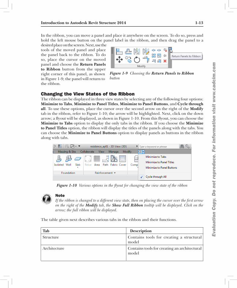
In the ribbon, you can move a panel and place it anywhere on the screen. To do so, press and hold the left mouse button on the panel label in the ribbon, and then drag the panel to a desired place on the screen. Next, use the
Figure 1-9 Choosing the Return Panels to Ribbon button
tools of the moved panel and place the panel back to the ribbon. To do so, place the cursor on the moved panel and choose the Return Panels to Ribbon button from the upper right corner of this panel, as shown in Figure 1-9; the panel will return to the ribbon.
changing the View States of the ribbonThe ribbon can be displayed in three view states by selecting any of the following four options: Minimize to Tabs, Minimize to Panel Titles, Minimize to Panel Buttons, and Cycle through all. To use these options, place the cursor over the second arrow on the right of the Modify tab in the ribbon, refer to Figure 1-10; the arrow will be highlighted. Next, click on the down arrow; a flyout will be displayed, as shown in Figure 1-10. From this flyout, you can choose the Minimize to Tabs option to display the only tabs in the ribbon. If you choose the Minimize to Panel Titles option, the ribbon will display the titles of the panels along with the tabs. You can choose the Minimize to Panel Buttons option to display panels as buttons in the ribbon along with tabs.
Figure 1-10 Various options in the flyout for changing the view state of the ribbon
noteIf the ribbon is changed to a different view state, then on placing the cursor over the first arrow on the right of the Modify tab, the Show Full Ribbon tooltip will be displayed. Click on the arrow; the full ribbon will be displayed.
The table given next describes various tabs in the ribbon and their functions.
Tab Description
Structure Contains tools for creating a structural model
Architecture Contains tools for creating an architectural model

1-14 Exploring Autodesk Revit StructureEva
lua
tion
Cop
y. D
o no
t re
prod
uce.
For
inf
orm
ati
on v
isit
ww
w.c
adc
im.c
om
Analyze Contains tools for analyzing the structural model
Insert Contains tools for inserting or managing secondary files such as raster image files and CAD files
Annotate Contains tools for documenting a building model such as adding texts and dimensions
Massing & Site Contains tools for creating massing and site elements
Collaborate Contains tools for collaborating the project with other team members (internal and external)
View C o n t a i n s t o o l s f o r m a n a g i n g and modifying the current views, switching views, and so on.
Manage Contains tools for specifying the project and system parameters and settings
Modify Contains tools for editing elements in the model
contextual tabs in the ribbonThese tabs are displayed when you choose certain tools or select elements. They contain a set of tools or buttons that relate only to a particular tool or element.
For example, when you invoke the Beam tool, the Modify | Place Beam contextual tab is displayed. This tab has the following panels: Select, Properties, View, Measure, Geometry, Clipboard, Create, Modify, Mode, Draw, and Multiple. The Select panel contains the Modify tool. The Properties panel contains the Properties button and the Type Properties tool. The Mode panel has some necessary tools that are used to load model families or to create the model of a window in a drawing. The other panels, apart from those discussed above, contain the tools that are contextual and are used to edit elements when they are placed in a drawing or selected from a drawing for modification.
Application frameThe application frame helps you manage projects in Autodesk Revit Structure. It consists of the Application button, Application Menu, Quick Access Toolbar, InfoCenter, and Status Bar. These are discussed next.
Application buttonThe Application button is displayed at the top-left corner of the Autodesk Revit Structure 2014 interface. This button is used to display as well as close the Application Menu.

Introduction to Autodesk Revit Structure 2014 1-15
Eva
lua
tion
Cop
y. D
o no
t re
prod
uce.
For
inf
orm
ati
on v
isit
ww
w.c
adc
im.c
om
Application menu The Application Menu contains tools that provide access to many common file actions such as Open, Close, and Save. Click on the down arrow on the Application button to display the Application Menu, as shown in Figure 1-11. Alternatively, press ALT+F to display tools in the Application Menu.
Figure 1-11 The Application Menu
Quick Access toolbarThe Quick Access Toolbar, shown in Figure 1-12, contains the options to undo and redo changes, open and save a file, create a new file, and so on.
Figure 1-12 The Quick Access Toolbar

1-16 Exploring Autodesk Revit StructureEva
lua
tion
Cop
y. D
o no
t re
prod
uce.
For
inf
orm
ati
on v
isit
ww
w.c
adc
im.c
om
By default, the Quick Access Toolbar contains the options such as Open, Save, Redo, Undo, and so on. You can customize the display of the Quick Access Toolbar by adding more tools and removing the unwanted tools. To add a tool or a button from the panel of the ribbon to the Quick Access Toolbar, place the cursor over the button; the button will be highlighted. Next, right-click; a flyout will be displayed. Choose Add Quick Access Toolbar from the flyout displayed; the highlighted button will be added to the Quick Access Toolbar. The Quick Access Toolbar can be customized to reorder the tools displayed in it. To do so, choose the down arrow next to the Switch Windows drop-down, refer to Figure 1-12; a flyout will be displayed. Choose the Customize Quick Access Toolbar option located at the bottom of the flyout; the Customize Quick Access Toolbar dialog box will be displayed. Use various options in this dialog box and choose the OK button; the Customize Quick Access Toolbar dialog box will close and the tools in the Quick Access Toolbar will be reordered.
infocenterYou can use InfoCenter to search for information related to Revit Structure (Help), to display the Subscription Center panel for subscription services and product updates, and to display the Favorites panel to access saved topics. Figure 1-13 displays various tools in InfoCenter.
Figure 1-13 The InfoCenter
Status barThe Status Bar is located at the bottom of the interface screen. When the cursor is placed over an element or a component, the Status Bar displays the name of the family and type of the corresponding element or components. It also displays prompts and messages to help you use the selected tools.
View control barThe View Control Bar is located at the lower left corner of the drawing window, as shown in Figure 1-14. It can be used to access various view-related tools. The Scale button shows the scale of the current view. You can choose this button to display a flyout that contains standard drawing scales. From this flyout, you can then select the scale for the current view. The Detail Level button is used to set the detail level of a view. You can select the required detail level as Coarse, Medium, and Fine. Similarly, the Visual Style button enables you to set the display style. The options for setting the display style are: Wireframe, Hidden Line, Shaded, Consistent Colors, Shaded, and Raytrace.

Introduction to Autodesk Revit Structure 2014 1-17
Eva
lua
tion
Cop
y. D
o no
t re
prod
uce.
For
inf
orm
ati
on v
isit
ww
w.c
adc
im.c
om
Figure 1-14 The View Control Bar
options barThe Options Bar provides information about the common parameters of a component type. It also displays options for creating or editing them. The options displayed in the Options Bar changes depend on the type of component being created and selected for editing. Figure 1-15 displays the options in the Options Bar to create a structural column.
Figure 1-15 The Options Bar with different options to create a structural column
type SelectorThe Type Selector drop-down list is located in the Properties palette for the currently invoked tool. On invoking the Beam tool, the properties of the beam will be displayed in the Properties palette. In this palette, you can use the Type Selector drop-down list to select the required type of the beam. The content in the Type Selector drop-down list keep changing, depending upon the current function of the tool or the elements selected. The Type Selector drop-down list can also be used to specify the type of this element or component while placing an element or a component in a drawing by using the Place a Component tool. You can also use this drop-down list to change the type of a selected element.
drawing AreaThe Drawing Area is the actual modeling area, where you can create and view the building model. It covers the major portion of the interface screen. You can draw building components in this area. The position of the pointing device is represented by the cursor. The Drawing Area also has the standard Microsoft Windows functions and buttons such as close, minimize, maximize, scroll bar, and so on. These buttons have the same function as that of the other Microsoft Windows-based programs.
project broWSerThe Project Browser is located below the ribbon. It displays project views, schedules, sheets, families, and groups in a logical, tree-like structure, as shown in Figure 1-16 and helps you open and manage them. To open a view, double-click on the name of the view, or drag and drop the view in the Drawing Area. You can close the Project Browser or dock it anywhere in the Drawing Area.

1-18 Exploring Autodesk Revit StructureEva
lua
tion
Cop
y. D
o no
t re
prod
uce.
For
inf
orm
ati
on v
isit
ww
w.c
adc
im.c
om
noteIf the Project Browser is not displayed on the screen,
Figure 1-16 The Project Browser
choose the View tab from the ribbon and then select the Project Browser check box from View > Windows > User Interface drop-down.
The Project Browser can be organized to group the views and sheets based on the project requirement. For example, while working on a large project with a number of sheets, you can organize the Project Browser to view and access specific sheets.
noteIn the Project Browser, you can expand or contract the view listing by selecting the ‘+’ or ‘-’ sign, respectively. The current view in the drawing window is highlighted in bold letters. The default project file has a set of preloaded views.
Keyboard AcceleratorsIn Autodesk Revit Structure, accelerator keys have been assigned to some of the frequently used tools. These keys are shortcuts that you can type through the keyboard to invoke the corresponding tool. Accelerator keys corresponding to a tool appear as a tooltip when you move the cursor over the tool.
properties paletteThe Properties palette, as shown in Figure 1-17, is a
Figure 1-17 The Properties palette
modeless interface, which displays the type and element properties of various elements and views in a drawing. The Properties palette is dockable and resizable, and it supports multiple monitor configurations. The Properties palette is displayed in the Revit interface by default and it shows the instance properties of an active view. When you select an element from a drawing, the Properties palette displays its instance properties. You can also access the type properties of the selected element from the Properties palette. To do so, choose the Edit Type button from the palette; the Type Properties dialog box will be displayed. In this dialog box, you can change the type properties of the selected element.
In the Properties palette, you can assign a type to a selected element in a drawing from the Type Selector drop-down list. In Revit Structure, you can toggle the display of the Properties palette
Introduction to Autodesk Revit Structure 2014 1-19
Eva
lua
tion
Cop
y. D
o no
t re
prod
uce.
For
inf
orm
ati
on v
isit
ww
w.c
adc
im.c
om
in its interface. Choose the Properties button in the Properties panel of the Modify tab to hide it. Similarly, you can choose the Properties button to display the palette if it is not visible in the interface.
tip: As you become accustomed to use Autodesk Revit Structure, you will find these Keyboard Accelerators quite useful because they save the effort of browsing through the menus.
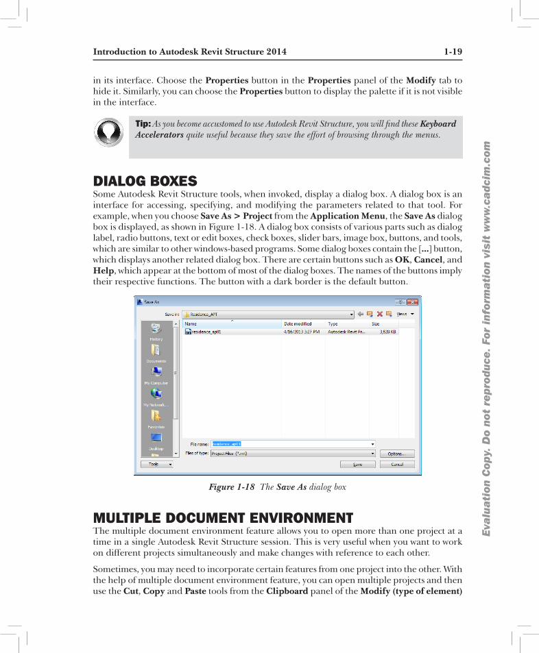
diAlog boxeSSome Autodesk Revit Structure tools, when invoked, display a dialog box. A dialog box is an interface for accessing, specifying, and modifying the parameters related to that tool. For example, when you choose Save As > Project from the Application Menu, the Save As dialog box is displayed, as shown in Figure 1-18. A dialog box consists of various parts such as dialog label, radio buttons, text or edit boxes, check boxes, slider bars, image box, buttons, and tools, which are similar to other windows-based programs. Some dialog boxes contain the [...] button, which displays another related dialog box. There are certain buttons such as OK, Cancel, and Help, which appear at the bottom of most of the dialog boxes. The names of the buttons imply their respective functions. The button with a dark border is the default button.
Figure 1-18 The Save As dialog box
multiple document enVironmentThe multiple document environment feature allows you to open more than one project at a time in a single Autodesk Revit Structure session. This is very useful when you want to work on different projects simultaneously and make changes with reference to each other.
Sometimes, you may need to incorporate certain features from one project into the other. With the help of multiple document environment feature, you can open multiple projects and then use the Cut, Copy and Paste tools from the Clipboard panel of the Modify (type of element)

1-20 Exploring Autodesk Revit StructureEva
lua
tion
Cop
y. D
o no
t re
prod
uce.
For
inf
orm
ati
on v
isit
ww
w.c
adc
im.c
om
tab to transfer the required components from one project to another. These editing tools can also be invoked by using the CTRL+C and CTRL+V keyboard shortcuts.
To access the opened projects, click
Figure 1-19 Selecting an option from the Switch Windows drop-down list
on the Switch Windows drop-down list in the Windows panel of the View tab; the options for the names of different opened project files will be displayed, as shown in Figure 1-19. Like other Microsoft Windows-based programs, you can select and view the opened projects using the Cascade and Tile tools from the
Windows panel of the View tab. The cascaded view of projects is shown in Figure 1-20.
Figure 1-20 The cascaded view of projects
interoperAbility of Autodesk revit StructureThe models or geometries created in Autodesk Revit Structure can be easily exported to AutoCAD and AutoCAD Architecture in the DWG file format. This enables structural engineers to collaborate with Architects.
One of the important aspects of the job of a structural engineer is to collaborate and share information with the rest of the design team including the architect. To facilitate this requirement, Revit Structure 2014 follows a wide range of industry standards and supports various CAD file formats such as DWF, DGN, DWG, DGN, IFC, SKP, and SAT. For image files, it supports JPG, TIFF, BMP, PNG, AVI, PAN, IVR, and TGA file formats. Besides these, the formats that are supported by Revit Structure include ODBC, HTML, TXT, XML, XLS, and MDB. Autodesk Revit Structure is compatible with any CAD system that supports the DWG, DXF, or DGN file format. Revit Structure can import the models and geometries as ACIS
Introduction to Autodesk Revit Structure 2014 1-21
Eva
lua
tion
Cop
y. D
o no
t re
prod
uce.
For
inf
orm
ati
on v
isit
ww
w.c
adc
im.c
om
solids. This enables engineers to import models from AutoCAD Architecture and AutoCAD MEP (Mechanical, Electrical, and Plumbing) software and to link and import 3D information to Revit Structure. This feature makes Autodesk Revit Structure 2014 an efficient, user-friendly, and compatible software.
building informAtion modeling And Autodesk revit Structure 2014Building Information Modeling (BIM) is defined as a design technology that involves the creation and use of coordinated, internally consistent, and computable information about a building project in design and construction.
Using BIM, you can demonstrate the entire life cycle of a building project starting from the process of construction, facility operation, and information about quantities and shared properties of elements. BIM enables the circulation of virtual information model from the design team to contractors and then to the owner, thereby adding changes and their knowledge to update the model at each stage of transfer. The ability to keep information up-to-date and make it available in an integrated digital environment enable the architects, owners, builders, and engineers to have clear vision of the project before the commencement of actual construction. It also enables them to make better and faster decisions to improve the quality and profitability of projects. Autodesk Revit Structure 2014 is a specially designed platform based on BIM.
In Revit Structure, the analytical and physical representations of a structural model are created simultaneously. These representations are just different views of a computable building model that contains necessary information for a third-party analysis application. Revit Structure provides a common modeling interface for third-party analysis applications. You can use Revit API to move data directly from the Revit Structure building information model to the analysis software. You can further bring back the analysis while keeping the analysis, design, and documentation synchronized.
Revit Structure’s parametric model represents a building as an integrated database of coordinated information. In Revit, change anywhere is change everywhere. A change made in your project at any stage is reflected in the entire project, and also, due to the parametric behavior of elements, the project is updated automatically. Also, the integration of Revit Structure with the available in-built commercial tools such as solar studies, material takeoffs, and so on greatly simplifies the project design and reduces the time consumed by these analyses, thereby enabling faster decision making.
WorKShAring uSing reVit SerVer Worksharing is a method of distributing work among people involved in a project, and accomplishing it within the stipulated period of time. In worksharing, each person involved in the project is assigned a task that has to be accomplished through proper planning and by coordinating with the other members of the team. In a large scale building project, worksharing helps in finishing a project in time and meeting the quality requirements that are set during the process. Generally, in a large scale building

1-22 Exploring Autodesk Revit StructureEva
lua
tion
Cop
y. D
o no
t re
prod
uce.
For
inf
orm
ati
on v
isit
ww
w.c
adc
im.c
om
project, worksharing is based on the specialization of work. The professionals such as structural engineers, architects, interior architects, and MEP engineers are involved in their respective fields to accomplish the project. So, the distribution of work at the primary stage is made on the basis of the area of specialization. Each professional has his own set of work to perform for the accomplishment of the project. Therefore, worksharing is an important process that is required to be implemented efficiently to complete the project in time. In Autodesk Revit Structure, you can apply server-based worksharing with the help of Revit Server, which is a server application. Revit Server uses a central server and multiple local servers for collaborating across a Wide Area Network (WAN). The central server hosts the central model of a workshared project and remain accessible to all team members over the Wide Area Network. Similarly, the local server is accessible to all team members in a Local Area Network (LAN). The local server hosts a local updated copy of the central model. In the Worksharing environment, the team members are not aware of the local server, as it is transparent in their daily operations. Refer to Figure 1-21 for the network model of Revit Server.
Figure 1-21 The Network Model of Revit Server
In Worksharing environment, a team member starts working on the local model of the central model. The local model will be saved in the computer of the team member. As the team member works, the local server requests updated information from the central model on the central server, using available network capacity to transfer the data over the WAN. The updated version of the model is stored on the local server, so the updates are readily available when a team member requests them.

Introduction to Autodesk Revit Structure 2014 1-23
Eva
lua
tion
Cop
y. D
o no
t re
prod
uce.
For
inf
orm
ati
on v
isit
ww
w.c
adc
im.c
om
linKing AnAlyticAl model to AnAlySiSIn Autodesk Revit Structure, the physical model represents the physical layout that consists of structural walls, beams, columns, footings, and so on. The analytical model is created along with the physical model. The analytical model is the engineering description of a structural physical model.
The following elements have analytical model associated with them: Structural Columns, Structural Framing elements (such as beams and braces), Structural Floors, Structural Footings, and Structural Walls. The analytical model is a 3D model that is used for structural analysis. In this model, you can add loads and material properties that are required for analysis. To analyze the analytical model, transfer it into a third-party analysis software. You can link the analytical model via application programming interface (API) to several leading industry applications for building analysis, such as ADAPT-Builder, RISA 3D, Fastrack, ROBOT Millennium, Sofistik, and others. After the analysis has been performed, the results of the analysis are returned to the building model (physical and analytical) in Revit Structure. The results that are returned to Revit Structure, dynamically update the building model and the documentation associated with it.
Autodesk revit Structure helpAutodesk Revit Structure 2014 helps you to easily understand the tools and methods used in a project. In Autodesk Revit Structure 2014, you can access online help documentation (Autodesk WikiHelp) as well as local (offline) help documentation.
To access the help feature, click on the Help down arrow on the right of the InfoCenter; a flyout with various help options will be displayed. The options to access the help are discussed next.
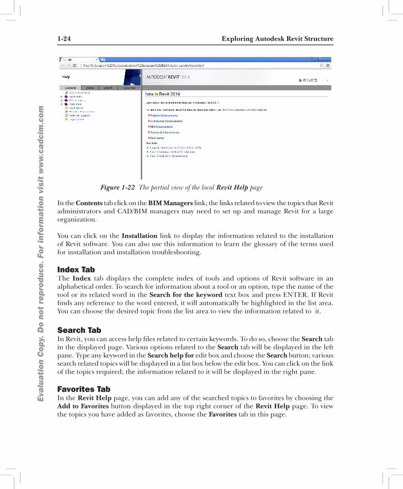
using the local revit Structure 2014 help To access the local Revit Structure 2014 help, choose the Help tool from InfoCenter; the Revit Help page will be displayed, as shown in Figure 1-22. You can also display the Revit Help page by pressing the F1 key. You can use this page to get information on various tools and enhancements introduced in Autodesk Revit 2014. There are four tabs provided in this page. The options in these tabs will help you speed up the search process. These tabs are discussed next.
contents tabThis tab is chosen by default. There are following links displayed in the left pane of the Contents tab: Revit Users, BIM Managers, and Installation. If you click on the Revit Users link, the user’s guide and information to various help topics in Revit software (MEP, Architecture, and Structure) are displayed in the right pane. You can click on the required link to view the desired topic.
1-24 Exploring Autodesk Revit StructureEva
lua
tion
Cop
y. D
o no
t re
prod
uce.
For
inf
orm
ati
on v
isit
ww
w.c
adc
im.c
om
Figure 1-22 The partial view of the local Revit Help page
In the Contents tab click on the BIM Managers link; the links related to view the topics that Revit administrators and CAD/BIM managers may need to set up and manage Revit for a large organization.
You can click on the Installation link to display the information related to the installation of Revit software. You can also use this information to learn the glossary of the terms used for installation and installation troubleshooting.
index tabThe Index tab displays the complete index of tools and options of Revit software in an alphabetical order. To search for information about a tool or an option, type the name of the tool or its related word in the Search for the keyword text box and press ENTER. If Revit finds any reference to the word entered, it will automatically be highlighted in the list area. You can choose the desired topic from the list area to view the information related to it.
Search tabIn Revit, you can access help files related to certain keywords. To do so, choose the Search tab in the displayed page. Various options related to the Search tab will be displayed in the left pane. Type any keyword in the Search help for edit box and choose the Search button; various search related topics will be displayed in a list box below the edit box. You can click on the link of the topics required; the information related to it will be displayed in the right pane.
favorites tabIn the Revit Help page, you can add any of the searched topics to favorites by choosing the Add to Favorites button displayed in the top right corner of the Revit Help page. To view the topics you have added as favorites, choose the Favorites tab in this page.

Introduction to Autodesk Revit Structure 2014 1-25
Eva
lua
tion
Cop
y. D
o no
t re
prod
uce.
For
inf
orm
ati
on v
isit
ww
w.c
adc
im.c
om
The New in Revit 2014 area of the offline help page information resources about enhancements in Autodesk Revit and other softwares related to the same platform.
The Platform Enhancements node contains information about enhancements in Revit softwares namely Revit Structure, Revit Architecture, and Revit MEP.
The Structural Enhancements node in this page contains information about the enhanced features in Autodesk Revit Structure 2014. In Revit Structure 2014 the enhancements in reinforcement, positioning for structural framing, structural analysis, and multi-rebar annotations are introduced.
The Architectural Enhancements node contains enhancements information exclusively for Revit Architecture application.
The MEP Enhancements node contains information about enhanced features in Revit MEP.
using the Autodesk Wikihelp In Autodesk Revit Structure 2014, Autodesk WikiHelp has been introduced to access various help topics online. You can access Autodesk WikiHelp for Revit Structure by choosing the Help tool from the InfoCenter. On doing so, the Autodesk WikiHelp page will be displayed, as shown in Figure 1-23. On this page, different areas such as Browse Help, Add Knowledge, Most Popular, Recent Updates, and Newest Videos are displayed. In these areas, you can click on the required link to get the related information.
In the Browse help area, various help options related to Autodesk Revit are available. You can click on the required option to display the help page corresponding to the option. The Add Knowledge area contains various learning resources. You can click on the desired option in this area to get the information related to it. The Recent Updates area displays latest updates made in Revit 2014.
using the context Sensitive helpIf you need help specific to a selected tool or a dialog box, Autodesk Revit Structure provides several options to access the relevant information. Many dialog boxes contain the Help tool and can be used to view help for the options of that dialog box and related topics. If the Help button is not available, you can press the F1 key, while the dialog box is open, to access the related information. To inquire a tool, place the cursor over it; a Help message box will be displayed. Now, you can press the F1 key to view more help contents pertaining to the button, in a separate window. To turn off the Help tooltips for buttons, choose the Options button from Application Menu; the Options dialog box will be displayed. In the User Interface tab of this dialog box, select the None option from the Tooltip assistance drop-down list in the Tooltips area. Now, choose OK to close the Options dialog box.

1-26 Exploring Autodesk Revit StructureEva
lua
tion
Cop
y. D
o no
t re
prod
uce.
For
inf
orm
ati
on v
isit
ww
w.c
adc
im.c
om
Figure 1-23 The Autodesk WikiHelp page