c. · solid angle acceptance. the energy and the direction of the particle ... conic· pins. a 50...
TRANSCRIPT
129
SOME PROPERTIES OF THE STREAMER TUBE SYSTEM OF THE CHARM NEUTRINO DETECTOR
(CERN-Hamburg-Amsterdam-Rome-Moscow Collaboration)
F. Bergsma, J. Dorenbosch, M. Jonker, C. Nieuwenhuis and F. Udo
NIKHEF, Amsterdam, The Netherlands
J.V. Allaby, U. Amaldi, G. Barbiellini 1), L. Barone 2),
A. Capone 2), W. Flegel, M. Metcalf, J. Panman and K. Winter
CERN, Geneva, Switzerland
I. Abt, J. Aspiazu, F.W. Busser, H. Daumann, P.D. Gall, E. Metz,
F. Niebergall, K.H. Ranitzsch and P. Stahelin
II. lnstitut fur Experimentalphysik*), Universitat Hamburg, Hamburg, Germany
P. Gorbunov, E. Grigoriev, V. Kaftanov, V. Khovansky and A. Rosanov
Institute for Theoretical and Experimental Physics, Moscow, USSR
A. Baroncel1i 3), B. Borgia4
), C. Bosio 3), F. Ferroni4
), E. Longo4 ),
L. Luminari 4), P. Monacelli4
), F. de Notaristefani 4 ), P. Pistilli4 ),
c. Santoni 3), L. Tortora 3) and V. Valente 5 )
Istituto Nazionale di Fisica Nucleare, Rome, Italy
Presented by W. Flegel at the Gas Sampling Calorimetry Workshop
Fermilab, Batavia, Ill., 28-29 October 1982
1) On leave of absence from the Laboratori Nazionali dell'INFN, Frascati, Italy.
2) On leave of absence from the Istituto di Fisica, Universita di Roma, and INFN, Sezione di Roma, Rome, Italy.
3) INFN, Sezione Sanita and Istituto Superiore di Sanita, Rome, Italy. 4) Istituto di Fisica, Universita di Roma, and INFN, Sezione di Roma, Rome,
Italy. 5) Laboratori Nazionali dell'INFN, Frascati, Italy. *) Supported by Bundesministerium fur Forschung und Technologie, Bonn,
Fed. Rep. Germany.
130
ABSTRACT
The fine-grain and low-density neutrino calorimeter of the CHARM
Collaboration has been designed to measure the energy and the direction of
particle showers. To further improve the spatial resolution the calori
meter has been upgraded by adding 20,000 aluminium tubes, working in the
limited streamer mode. Each subunit is now equipped with crossed wire
planes. Results of a new energy calibration of the upgraded detector using
electron and pion beams from 5 to 140 GeV/c, and on the angular and spatial
resolution are presented. The use of the streamer tube system to discri
minate between electromagnetic and hadronic showers is discussed.
INTRODUCTION
The CHARM detector was designed for the study of different reactions
induced by high~energy neutrinos, in particular for a kinematically complete
measurement of the neutral-current scattering of v (v) on nucleons and p ~
electrons. This requires a clear separation of the neutral-current reac
tions from the charged current ones with an outgoing muon, a precise mea
surement of the energy and of the direction of the shower initiated in the
process, and efficient discrimination between hadronic and electromagnetic
showers.
The CHARM Collaboration has constructed a fine-grain and low-density
sampling calorimeter of low-Z material «Z) ~ 13) in a modular construc
tion; the average density is 1.38 g/cm3 • It is followed by a muon spectro
meter. The calorimeter is built up of 78 equal subunits with marble plates
131 of 1 radiation length thickness (8 cm) as target material. Each plate is
surrounded by a magnetized iron frame for muon identification with large
solid angle acceptance. The energy and the direction of the particle
showers, as they develop in the target plates, are measured with hodo
scopes of scintillation counters and proportional drift tubes. The CHARM
detector has been described in detail elsewhere l ).
To improve the spatial resolution of the measurement of the direction
of electromagnetic showers -- as, for example, in the study of v~e elastic
scattering -- 77 subunits of the calorimeter were completed by a plane of
256 streamer tubes each. Its wires are oriented at 90 0 with respect to the
proportional tube wires, thereby providing accurate lateral sampling in
two orthogonal projections 2 ,3) in each subunit.
In this paper we report on the construction of these tubes and on some
results of the new energy calibration of the upgraded detector in a test
beam containing negative pions and electrons, together with data on the
angular and spatial resolution of shower measurements.
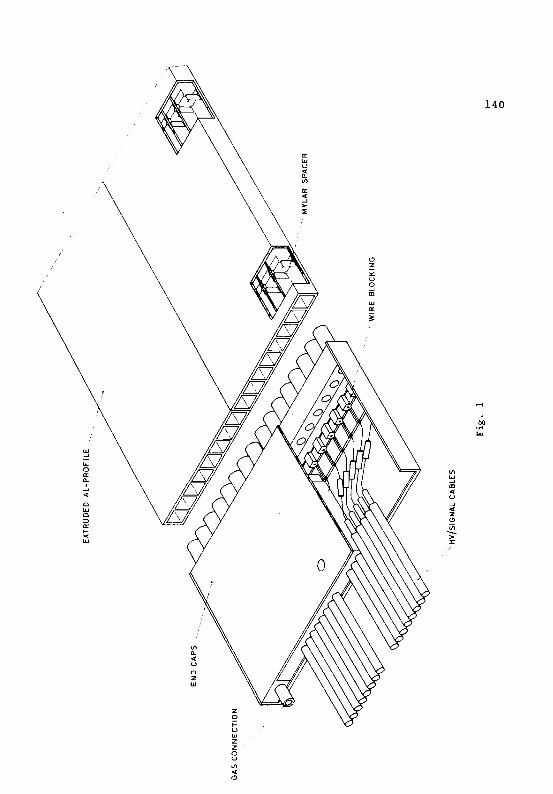
THE STREAMER TUBE SYSTEM
Some details of the construction of the streamer tube system are shown
in Fig. 1. Two extruded Al profiles of eight cells each are glued together
to form one chamber; sixteen chambers make one plane of about 265 em x 265 cm
sensitive area. The cell size is I em x 1 cm. Each end of a chamber is
sealed by a plastic cap, which also contains a wire blocking system with
conic· pins. A 50 ~m stainless-steel anode wire was chosen. It is centred
by mylar spacers every 50 em. The presence of the spacers did not create
132 any electrical problems, discharges or dead zones. Because of restrictions
in the available space, the high voltage is fed in via 125 cm long, 50 n, coaxial cables, which serve s~ultaneously to transmit the signal from the
wire to the electronics.
A gas mixture of argon + isobutane in a ratio of 1:3 is used. This
leads to a working anode voltage of about 3.7 kV, with a width of the
plateau of at least 500 V.
The streamer tube system works under these conditions in the limited
streamer mode, characterized by very large and rather uniform signals.
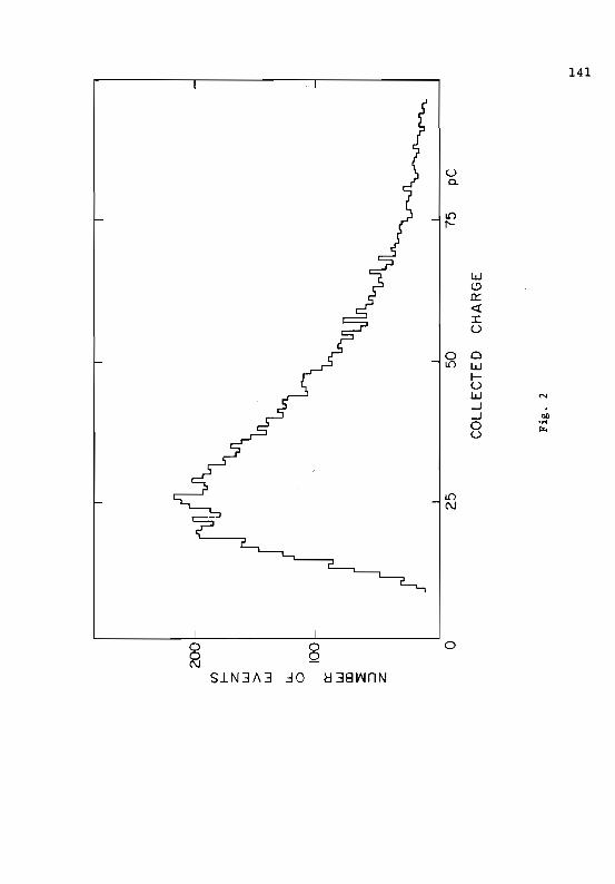
Fig. 2 shows a charge distribution for cosmics traversing one single streamer
tube. The mean charge is about 30 pC for an integration time of 500 ns and
an anode voltage of 3.7 kV. The trigger also accepted very inclined tracks,
thereby extending the charge distribution to very high values. These large
signals allow simple comparators to be used for the front-end electronics.
THE CALIBRATION OF THE CHARM DETECTOR AND ITS STREAMER TUBE ~YSTEM
The C~I calorimeter, upgraded with the planes of streamer tubes,
was calibrated in a test beam of negative pions and electrons~ in an
energy range of 5 to 140 GeV. Bending magnets allowed the beam to be
deflected horizontally to hit the detector at different points and with
different impact angles. For this calibration, 36 of the 78 identical
subunits of the target calorimeter were used.
For beam energies between 5 and 30 GeV, the electrons could be tagged
by a 20 m long helium-filled threshold Cerenkov counter; 50 GeV electrons .
were identified by the width of their shower profile. Above SO GeV the
133 electron component of the beam was less than 1%. For measurements with a
pure pion beam, a lead filter was placed in the beam. The beam intensity
was around 50 particles per pulse in a 30 ms spill. The central beam momen
tum was known to ±Iio; the fractional momentum spread was less than 1%.
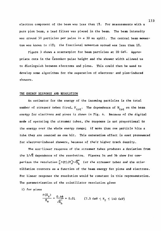
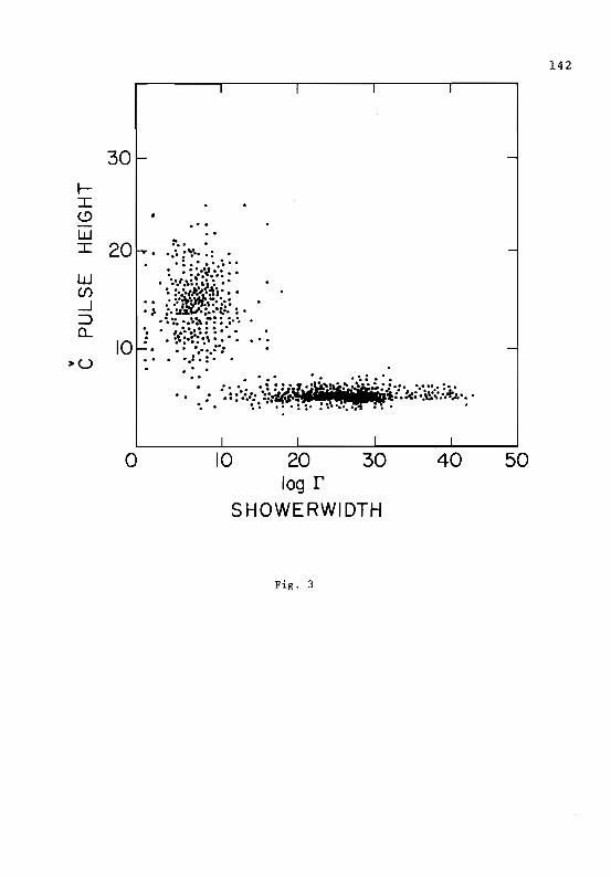
Figure 3 shows a scatterplot for beam particles at 20 GeV. Appro
priate cuts in the Cerenkov pulse height and the shower width allowed us
to distinguish between electrons and pions. This could then be used to
develop some algorithms for the separation of electron- and pion-induced
showers.
THE ENERGY RESPONSE AND RESOLUTION
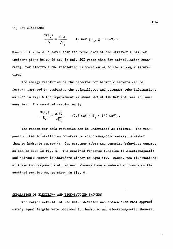
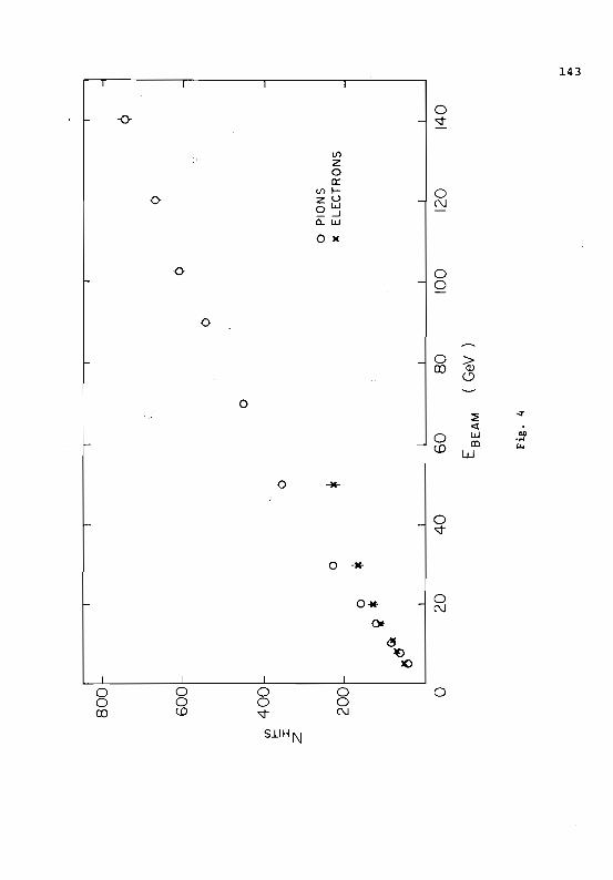
An estimator for the energy of the incoming particles is the total
number of streamer tubes fired, N • The dependence of N on the beamtot tot
energy for electrons and pions is shown in Fig. 4. Because of the digital
mode of operating the streamer tubes, the response is not proportional to
the energy over the whole energy range; if more than one particle hits a
tube they are counted as one hit. This saturation effect is most pronounced
for electron-induced showers, because of their higher track density.
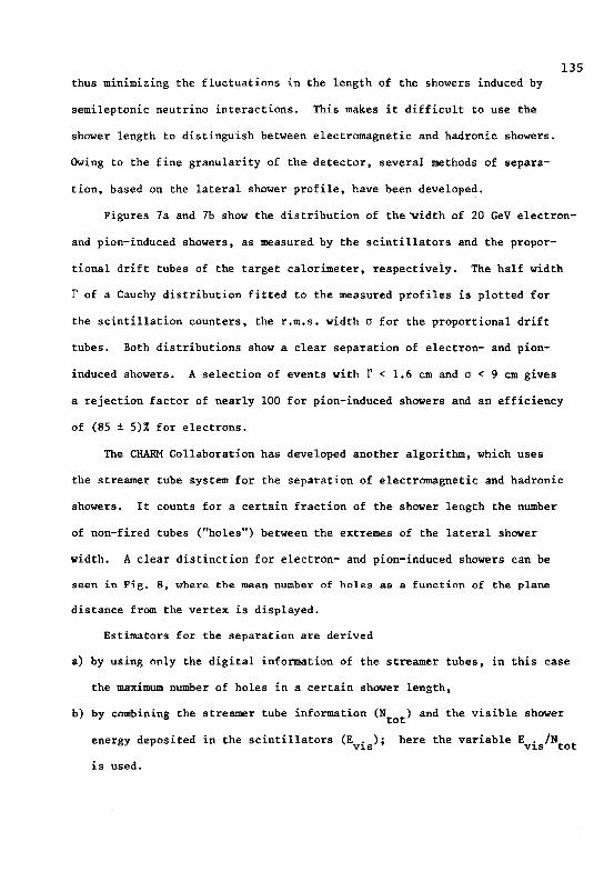
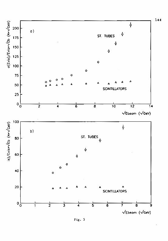
The non-linear response of the streamer tubes produces a deviation from
the lllE dependence of the resolution. Figures 5a and 5b show for com
parison the resolution [O(E)/EJ.~ for the streamer tubes and the scin
tillation counters as a function of the beam energy for pions and electrons.
For linear response the resolution would be constant in this representation.
The parametrization of the scintillator resolution gives
i) for pions
(7.5 GeV ~ En ~ 140 GeV)
134
ii) for electrons
(J (Ee) 0.20 -E (5 GeV ~ E ~ 50 GeV) . e
e ~
However it should be noted that the resolution of the streamer tubes for
incident pions below 20 GeV is only 20% worse than for scintillation coun
ters; for electrons the resolution is worse owing to the stronger satura
tion.
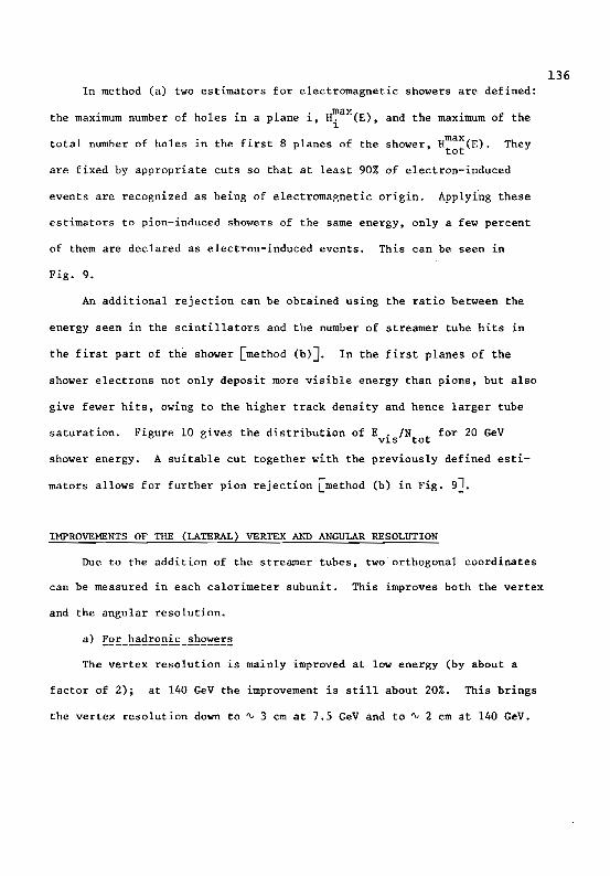
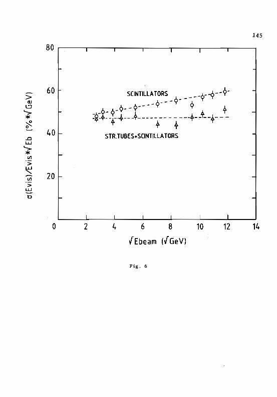
The energy resolution of the detector for hadronic showers can be
further improved by combining the scintillator and streamer tube information;
as seen in Fig. 6 the improvement is about 20% at 140 GeV and less at lower
energies. The combined resolution is
cr(E )1T _ 0.47
-E---1T ~
The reason for this reduction can be understood as follows. The res
ponse of the scintillation counters to electromagnetic energy is higher
than to hadronic energyl); for streamer tubes the opposite behaviour occurs,
as can be seen in Fig. 4. The combined response function to electromagnetic
and hadronic energy is therefore closer to equality. Hence, the fluctuations
of these two components of hadronic showers have a reduced influence on the
combined resolution, as shown in Fig. 6.
SEPARATION OF ELECTRON- AND PION-INDUCED SHOWERS
The target material of the CHARM detector was chosen such that approxi
mately equal lengths were obtained for hadronic and electromagnetic showers,
135 thus minimizing the fluctuations in the length of the showers induced by
semileptonic neutrino interactions. This makes it difficult to use the
shower length to distinguish between electromagnetic and hadronic showers.
Owing to the fine granularity of the detector, several methods of separa
tion, based on the lateral shower profile, have been developed.
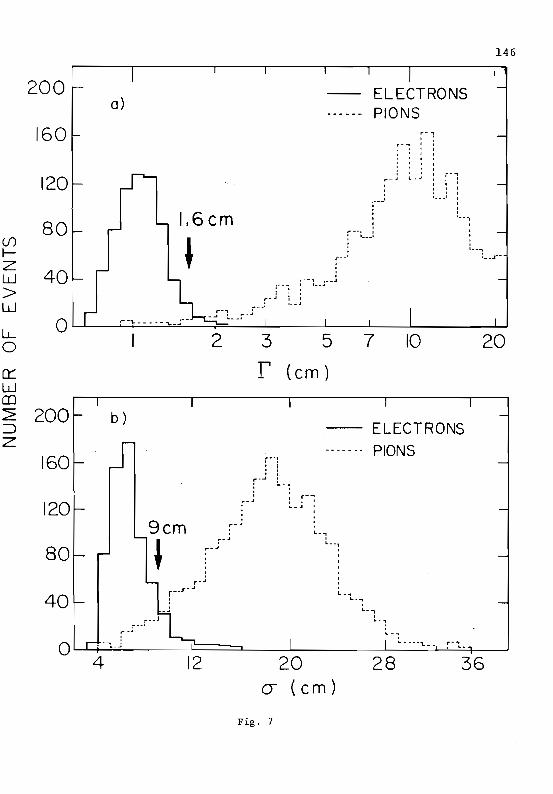
Figures 7a and 7b show the distribution of thevidth of 20 GeV electron
and pion-induced showers, as measured by the scintillators and the propor
tional drift tubes of the target calorimeter, respectively. The half width
r of a Cauchy distribution fitted to the measured profiles is plotted for
the scintillation counters, the r.m.s. width a for the proportional drift
tubes. Both distributions show a clear separation of electron- and pion
induced showers. A selection of events with r < 1.6 cm and a < 9 em gives
a rejection factor of nearly 100 for pion-induced showers and an efficiency
of (85 ± 5)% for electrons.
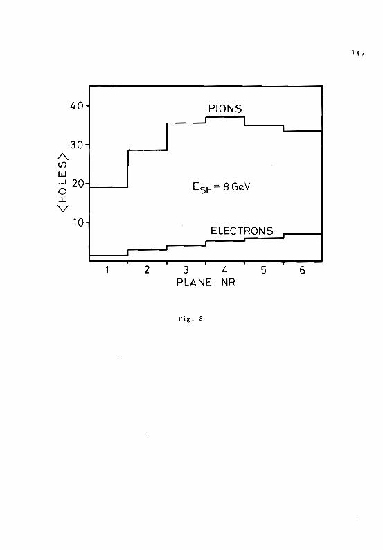
The CHARM Collaboration has developed another algorithm, which uses
the streamer tube system for the separation of electromagnetic and hadronic
showers. It counts for a certain fraction of the shower length the number
of non-fired tubes ("holes") between the extremes of the lateral shower
width. A clear distinction for electron- and pion-induced showers can be
seen in Fig. 8, where the mean number of holes as a function of the plane
distance from the vertex is displayed.
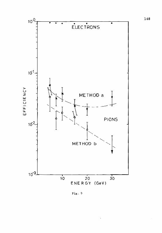
Estimators for the separation are derived
a) by using only the digital information of the streamer tubes, in this case
the maximum number of holes in a certain shower length,
b) by combining the streamer tube information (N ) and the visible showertot
energy deposited in the scintillators (Evis ); here the variable Evis/Ntot
is used.
136 In method (a) two estimators for electromagnetic showers are defined:
the maximum number of holes in a plane i, H~x(E), and the maximum of the 1
total number of holes in the first 8 planes of the shower, Hmax(E). Theytot
are fixed by appropriate cuts so that at least 90% of electron-induced
events are recognized as being of electromaenetic origin. Applying these
estimators to pion-induced showers of the same energy, only a few percent
of them are declared as electron-induced events. This can be seen in
Fig. 9.
An additional rejection can be obtained using the ratio between the
energy seen in the scintillators and the number of streamer tube hits in
the first part of the shower [method (b)J. In the first planes of the
shower electrons not only deposit more visible energy than pions, but also
give fewer hits, owing to the higher track density and hence larger tube
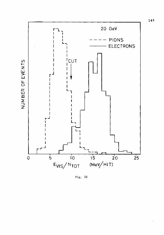
saturation. Figure 10 gives the distribution of Evis/Ntot for 20 GeV
shower energy. A suitable cut together with the previously defined esti
roators allows for further pion rejection [method (b) in Fig. 9J.
IMPROVEMENTS OF THE (LATERAL) VERTEX AND ANGULAR RESOLUTION
Due to the addition of the streamer tubes, two orthogonal coordinates
can be measured in each calorimeter subunit. This improves both the vertex
and the angular resolution.
The vertex resolution is mainly improved at law energy (by about a
factor of 2); at 140 GeV the improvement is still about 20%. This brings
the vertex resolution down to ~ 3 em at 7.5 GeV and to ~ 2 cm at 140 GeV.
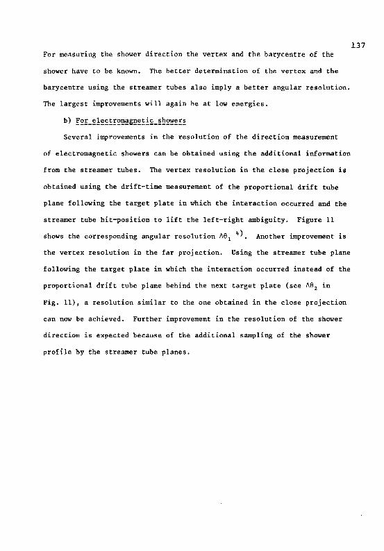
137 For measuring the shower direction the vertex and the barycentre of the
shower have to be known. The better determination of the vertex and the
barycentre using the streamer tubes also imply a better angular resolution.
The largest improvements will again be at low energies.
b) ~~!_~!~ct!~~~g~~!i~_~~~~!~
Several improvements in the resolution of the direction measurement
of electromagnetic showers can be obtained using the additional information
from the streamer tubes. The vertex resolution in the close projection is
obtained using the drift-time measurement of the proportional drift tube
plane following the target plate in which the interaction occurred and the
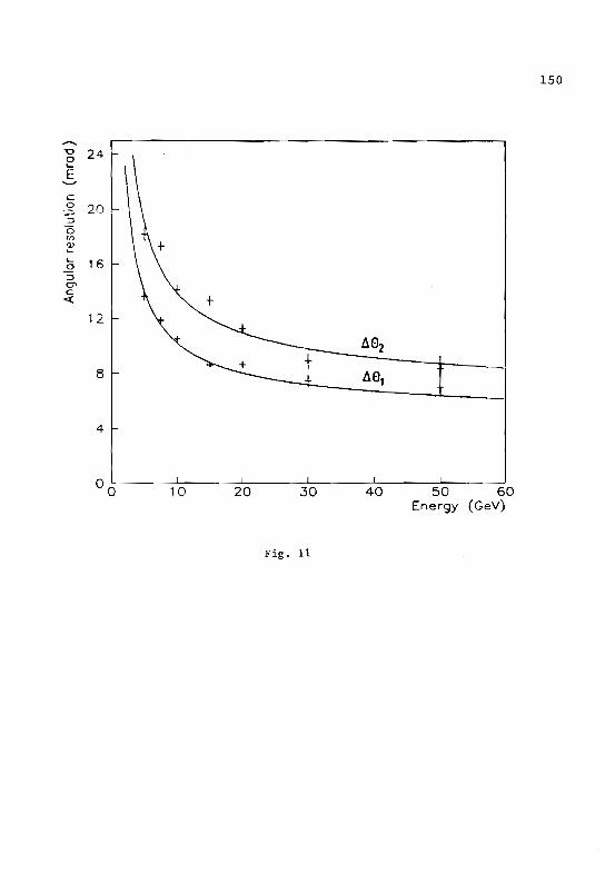
streamer tube hit-position to lift the left-right ambiguity. Figure 11
shows the corresponding angular resolution ~el 4). Another improvement is
the vertex resolution in the far projection. Using the streamer tube plane
following the target plate in which the interaction occurred instead of the
proportional drift tube plane behind the next target plate (see ~e2 in
Fig. 11), a resolution similar to the one obtained in the close projection
can now be achieved. Further improvement in the resolution of the shower
direction is expected because of the additional sampling of the shower
profile by the streamer tube planes.
138 References
1) A.N. Diddens et a1. (CHARM Collaboration)t Nucl. Instrum. Methods 178
(1980) 27.
M. Jonker et al. (CHARM Co11aboration)t Nucl. Instrum. Methods 200
(1982) 183.
2) M. Jonker et al., Phys. Scripta ~ (1981) 677.
References to the earlier literature can be found therein.
3) M. Jonker et a1. t The limited streamer tube system of the CHARM Colla
boration, to be published in Nucl. Instrum. Methods (1982).
4) M. Jonker, PhD Thesis, University of Amsterdam (1983).
139 Figure captions
Fig. 1 Some construction details of the streamer tubes.
Fig. 2 Charge distribution for cosmics traversing one tube with wide
angular spread.
Fig. 3 Scatter plot of the C-pulse height of beam particles and their
shower width.
Fig. 4 The response of the streamer tube system for pions and electrons.
Fig. 5 The energy resolution of the streamer tube system for a) pions
and b) electrons.
Fig. 6 The energy resolution of the scintillation counters and its
improvement with the streamer tubes.
Fig. 7 Distribution of the width of 20 GeV electron and pion showers.
as measured by a) the scintil1ators and b) the proportional
drift tubes.
Fig. 8 The mean number of holes between streamer tube hits for pions
and electrons as a function of the distance from the vertex.
Fig. 9 Efficiencies for electron and pion separation using the streamer
tubes.
Fig. 10 Distribution of the ratio of the visible energy in the scintil
lators and the streamer tube hits for electron- and pion-induced
showers.
Fig. 11 The angular resolution for electromagnetic showers in the close
(~el) and far (~e2) projection as a function of the energy.
140
/
~ LL. 0 a: 0
j ....J
< C w c ::::> ~ >< W
(!)
Z x: U
9 m w 0:
~
tn ~ m « u ....J <C Z (!)
~ >::r
bO •rot ~
tn Il. < U
C Z W
z o t= u w z z o U
tn < <!)
141
U a.
L() 1'
W 19 0:: <! I U
0 0 Ll) W
f-u W N
-J .-J 00
0 U
·rOI rz..
o o o QC\J
SlN3A3 ~O C:l38lAJnN
142
J I J
30
•• e
:e. o20 t-r. .:. :,:••••
: • : e' .' .e•••
:•• e. :~..~.:. ~ : •w • ••.•I:••••,.J&. :Cf) •••••~/I..,...~.' ••
.' :/M .,-:. :::--.J .,. :. ~ .;"-:'" : . :::::> .........\:,:-:: :... .� 0... '.. I.···.·~:~···: .....:.:': ~\ ·· '. ."I0 ~. .' .....:.: ..: .: .>U . . .. . '.' .. ... : ...
• • :::.: ~:.~~::.,: ~:.::l...'. . ... .e:~."". , ..;.: \:;.......;.. ·� e.. .. ~ · .. . ~ ~. :~ .:.... :~ . .
I I I I
o 10 20 30 40 50 log r
SHOWERWIDTH
Fig. 3
143 I r I 1
0 r -0 - ~
(/)
z 0 a:
(/) .....
ZU OW_..J
0 N
CLW
o )(
-0 0
0
0
- - 0 CO >Q)
<..9
0 ...r
~ «
- 0 to
W CD
W
00 -.-4 ~
0
- 0 ¢
0 ... 0* - 0
N Of
<!S ~
)()
I I I I
0 0 ro
0 0 lO
0 0 ~
0 0 C\J
0
S.LIH N
144 > ........�
Q) •� ~
200 ~ ~ a ) I
~ * 9ST. TUeES175 ... .D l.LJ 9'>
ott 150 ~ fI)
"S; Qw� "-........ 125 ~
fI)
"> (>l.LJ
100 ~b 0
75 ~ 0� 0�000 A AA�
50 ~ A A A A A A 6 ~
SCINTILLATORS
25 ~
I I I I I I
°0 2 4 6 8 10 12 14
'-"Ebeom <'-"GeV)
,......, 100� >�Q)
9 I
~ b).. ~ '-' ST. TUSES80 ~ Q..0
~ ott
QfI)
"> l.LJ 60 ~ 4)~ .!!?
6� 0�
40 ~ 0
20 ~ A A A A A A A
SCINTILLATORS
°0 I
1 I
2 I
3 I
4 I
5 I
6 I"
7 I
8 9
~Ebeom (~GeV)
Fig. 5
145
80 r-----,---.--------,---.....,....---r-------
60 >
QJ
L.:J "-> * ~ 0
40 ..CJ W
"->*CJ)
> ~
CJ) 20 >
L.L.J-b
o 2 4 6 8 10 12 ,14
{Ebeam ({GeV)
Fig. 6
146
200 ELECTRONSa) PIONS�
160� I
120 L._ r--:
~
I . ::
:I
I~ - ~I I I I
I
'---I1.6cm .-. I80 '- __"
,I
(f) I
t_--L_..t__t--- I-
Z .- -, JIw 40 ,--'""" I • __ •
j> W ..r U
- 1"-"L__ f - .:
0l.L 2 3 5 7 10 200
0::: r (em) W OJ ~ 200 b ) ::) -- ELECTRONS z ------- PIONS�
160�
120 gem
80 ~ 40
~-1 L • .,
L..,
L_,
L_ ...
• ~_.J :... ---'\.- - ~-~0
4 12 20 28 36 (J (em)
Fig. 7
147
..40 PIONS r I
I
-30 /\. (/)
W --I 20 a I V
ESH =8GeV
..10
1" .J
ELECTRONS .
2 3 PLANE
4 NR
5 6
Fig. B
148 1ao'--'-_~.-.-.--.--.-----.-----,
ELECTRONS�
> u
w l~ '---- METHOD a 1 U
LL
z
,,,~ ri----lL. W
10-3--------------------...------.. 10 20 30
ENERGY (GeV)
Fig. 9
149
r-L., I I I t I IL_, J I I I I I
IIf)�
: :C!UT Z I I W rJ>� I W I I LL I Io
I IL,0: IW CD I J
:2 I I :::> I I z I I
I I ,...J I I L 1 I I L.,
I I I I I I
20 GeV
---- PlONS
--- ELECTRONS
J""J L"""L-,r
o� 15 20 25 (MeV/HIT)
Fig. 10
150
~ :: t :::l
0 (f)
~
0\- 16 :; Q'\ C ~ +
12
8
4
10 20 30 40 50 60 Energy (GeV)
Fig. 11