c-frame mkiv - series circuit breakers · 2021. 2. 18. · cmkiv-series-dat rev. d february 2021...
TRANSCRIPT
low voltage
CMKIV-SERIES-DATREV. D
FEBRUARY 20212011003
Data SheetPage 1 of 6
Hydraulic-Magnetic Circuit Breakers 100% rated, unaffected by ambient temperature
C-Frame MKIV - Series Circuit Breakers
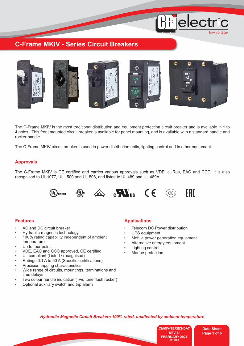
The C-Frame MKIV is the most traditional distribution and equipment protection circuit breaker and is available in 1 to 4 poles. This front mounted circuit breaker is available for panel mounting, and is available with a standard handle and rocker handle.
The C-Frame MKIV circuit breaker is used in power distribution units, lighting control and in other equipment.
Approvals
The C-Frame MKIV is CE certified and carries various approvals such as VDE, cURus, EAC and CCC. It is also recognised to UL 1077, UL 1500 and UL 508, and listed to UL 489 and UL 489A.
S
A005438
• AC and DC circuit breaker• Hydraulic-magnetic technology• 100% rating capability independent of ambient
temperature • Up to four poles• VDE, EAC and CCC approved, CE certified• UL compliant (Listed / recognised)• Ratings 0.1 A to 50 A (Specific certifications)• Precision tripping characteristics• Wide range of circuits, mountings, terminations and
time delays• Two colour handle indication (Two tone flush rocker)• Optional auxiliary switch and trip alarm
Features Applications• Telecom DC Power distribution• UPS equipment• Mobile power generation equipment• Alternative energy equipment• Lighting control• Marine protection

CMKIV-SERIES-DATREV. D
FEBRUARY 20212011003
Data SheetPage 2 of 6
low voltage
C-Frame MKIV - Series Circuit Breakers
Technical Data
Product Type Circuit Breaker Circuit Breaker SwitchApprovals IEC / EN 60934, CE, GB17701 UL 1500 UL 508Number of Poles 1 - 4 1, 2 1 - 4Maximum Voltages 240 Vac, 80 Vdc 120 / 240 Vac, 65 Vdc 240 Vac, 277 Vac, 80 VdcCurrent Ratings 50 A (AC & DC) 50 A 50 AInterrupting Capacity 2 kA (AC), 4 kA (DC) 1.5 kA -
Product Type Circuit Breaker Circuit Breaker Circuit BreakerApprovals UL 489 UL 489A UL 1077 Number of Poles 1, 2 1, 2 1 - 4Maximum Voltages 120 / 240 Vac 80 Vdc 240 Vac, 277 Vac, 80 VdcCurrent Ratings 0.05 - 20 Aac 0.05 - 50 Adc 0.05 - 50 A (AC & DC)Interrupting Capacity 5 kA 5 kA 2 kA (AC), 7.5 kA (DC)
Product Type C-Frame MKIVAmbient Operating Temperature -40 °C to +85 °C
Endurance
10000 operations DC, 6000 operations AC (IEC60934 Clause 9.11)*10000 operations, 6000 with current, 4000 without current (UL489 Clause 7.1.5)*
As per UL489 or minimum of 1000 operations with current (UL489A Clause 12)*, 6000 operations with current (UL1077 Clause 22)*
Dielectric Strength1000 - 2000 Vac for one minute (Clause 9.7)*
1000 Vac plus twice the rated voltage for one minute (UL489, Clause 7.1.9; UL489A Clause 8, UL1077 Clause 23)*
Weight 70 g per pole (unpacked)
Altitude Certification tests done at altitude ≈ 2000 metres. Will operate at higher altitudes.
Shock 100 G to MIL-STD-202G, test method 213B, test condition 1Vibration 10 G to MIL-STD-202G test method 204D, test condition AFlammability I2 - No ignition at 850 °C with an oxygen index of ≥ 32Toxicity F1 - Smoke index of ≤ 20 which determines the fume class
Pollution Degree PD2 - Normally only non-conductive pollution occurs. Temporary conductivity caused by condensation is to be expected.
* Refer to the standard for details
Verify approvals for specific ratings in accordance with the relevant test certificates.
Torque Table Description Size Torque Value
Front Inserts M3 0.5 - 0.8 Nm
6 - 32 5 - 7 in/Ibf
Rear ScrewsM5 1.7 - 2.3 Nm
10 - 32 15 - 20 in/Ibf
low voltage
CMKIV-SERIES-DATREV. D
FEBRUARY 20212011003
Data SheetPage 3 of 6
C-Frame MKIV - Series Circuit Breakers
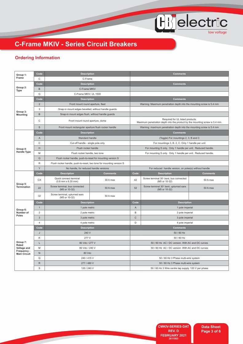
Group 1: Frame
Code Description Comments
C C-Frame
Group 2: Type
Code Description Comments
B C-Frame MKIV
G C-Frame MKIV, UL 1500
Group 3: Mounting
Code Description Comments
2 Front mount round aperture, fleet Warning: Maximum penetration depth into the mounting screw is 5.4 mm
3 Snap-in mount edges bevelled, without handle guards
B Snap-in mount edges flush, without handle guards
C Front mount round aperture, dome Required for UL listed products. Maximum penetration depth into the product by the mounting screw is 5.4 mm.
S Front mount rectangular aperture flush rocker handle Warning: maximum penetration depth into the mounting screw is 5.4 mm
Group 4: Handle Type
Code Description Comments
A Standard handle (Toggle) For mountings 2, 3, B and C
C Cut-off handle - single pole only For mountings 3, B, 2, C. Only 1 handle per unit
H Flush rocker handle For mounting S only. Only 1 handle per unit. Reduced handle.
M Flush rocker handle, two tone For mounting S only. Only 1 handle per unit. Reduced handle.
Q Flush rocker handle, push-to-reset for mounting version S
R Flush rocker handle, push-to-reset, two tone for mounting version S
Y No handle, for reduced handle versions For reduced handle version, on poles(s) without handle
Group 5:Termination
Code Description Comments Code Description Comments
CX Quick connect terminal (0.8 mm x 6.35 mm) 30 A max 42 Screw terminal 30o bent, bus connected
(M5 or 10-32) 50 A max
22 Screw terminal, bus connected (M5 or 10-32) 50 A max 52 Screw terminal 30o bent, upturned ears
(M5 or 10-32) 50 A max
32 Screw terminal, upturned ears(M5 or 10-32) 50 A max
Group 6: Number of Poles
Code Description Code Description
1 1 pole metric A 1 pole imperial
2 2 pole metric B 2 pole imperial
3 3 pole metric C 3 pole imperial
4 4 pole metric D 4 pole imperial
Group 7: Rated Voltage and Frequency - Main Circuit
Code Description Comments
J 240 V 50 / 60 Hz
K 277 V 50 / 60 Hz
L 80 Vdc / 277 V 50 / 60 Hz AC / DC version. With AC and DC curves
M 80 Vdc / 240 V 50 / 60 Hz AC / DC version. With AC and DC curves
N 80 Vdc
Q 240 / 415 V 50 / 60 Hz 3 Phase multi-wire system
R 277 / 480 V 50 / 60 Hz 3 Phase multi-wire system
S 120 / 240 V 50 / 60 Hz 3 Wire centre tap supply. 120 V per phase
Ordering Information
CMKIV-SERIES-DATREV. D
FEBRUARY 20212011003
Data SheetPage 4 of 6
low voltage
C-Frame MKIV - Series Circuit Breakers
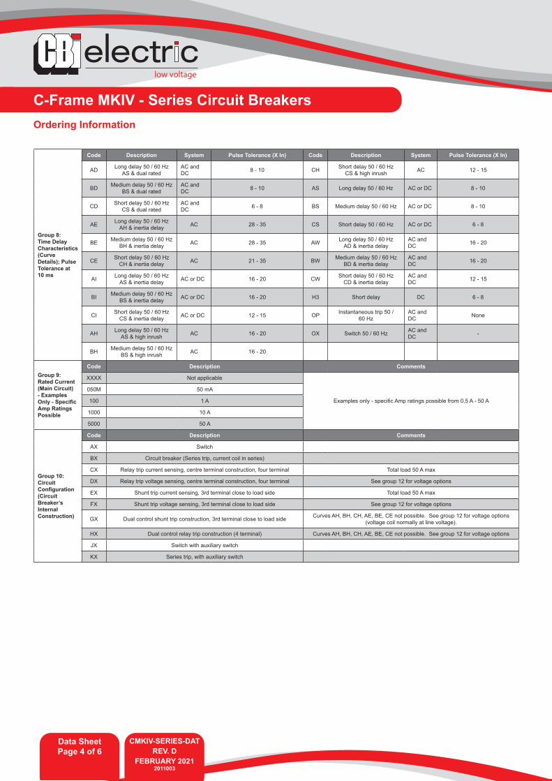
Group 8: Time Delay Characteristics (Curve Details); Pulse Tolerance at 10 ms
Code Description System Pulse Tolerance (X In) Code Description System Pulse Tolerance (X In)
AD Long delay 50 / 60 HzAS & dual rated
AC and DC 8 - 10 CH Short delay 50 / 60 Hz
CS & high inrush AC 12 - 15
BD Medium delay 50 / 60 HzBS & dual rated
AC and DC 8 - 10 AS Long delay 50 / 60 Hz AC or DC 8 - 10
CD Short delay 50 / 60 HzCS & dual rated
AC and DC 6 - 8 BS Medium delay 50 / 60 Hz AC or DC 8 - 10
AE Long delay 50 / 60 HzAH & inertia delay AC 28 - 35 CS Short delay 50 / 60 Hz AC or DC 6 - 8
BE Medium delay 50 / 60 HzBH & inertia delay AC 28 - 35 AW Long delay 50 / 60 Hz
AD & inertia delayAC and DC 16 - 20
CE Short delay 50 / 60 HzCH & inertia delay AC 21 - 35 BW Medium delay 50 / 60 Hz
BD & inertia delayAC and DC 16 - 20
AI Long delay 50 / 60 HzAS & inertia delay AC or DC 16 - 20 CW Short delay 50 / 60 Hz
CD & inertia delayAC and DC 12 - 15
BI Medium delay 50 / 60 HzBS & inertia delay AC or DC 16 - 20 H3 Short delay DC 6 - 8
CI Short delay 50 / 60 HzCS & inertia delay AC or DC 12 - 15 OP Instantaneous trip 50 /
60 HzAC and DC None
AH Long delay 50 / 60 HzAS & high inrush AC 16 - 20 OX Switch 50 / 60 Hz AC and
DC -
BH Medium delay 50 / 60 HzBS & high inrush AC 16 - 20
Group 9: Rated Current (Main Circuit) - Examples Only - Specific Amp Ratings Possible
Code Description Comments
XXXX Not applicable
Examples only - specific Amp ratings possible from 0.5 A - 50 A
050M 50 mA
100 1 A
1000 10 A
5000 50 A
Group 10: Circuit Configuration (Circuit Breaker’s Internal Construction)
Code Description Comments
AX Switch
BX Circuit breaker (Series trip, current coil in series)
CX Relay trip current sensing, centre terminal construction, four terminal Total load 50 A max
DX Relay trip voltage sensing, centre terminal construction, four terminal See group 12 for voltage options
EX Shunt trip current sensing, 3rd terminal close to load side Total load 50 A max
FX Shunt trip voltage sensing, 3rd terminal close to load side See group 12 for voltage options
GX Dual control shunt trip construction, 3rd terminal close to load side Curves AH, BH, CH, AE, BE, CE not possible. See group 12 for voltage options(voltage coil normally at line voltage).
HX Dual control relay trip construction (4 terminal) Curves AH, BH, CH, AE, BE, CE not possible. See group 12 for voltage options
JX Switch with auxiliary switch
KX Series trip, with auxiliary switch
Ordering Information
low voltage
CMKIV-SERIES-DATREV. D
FEBRUARY 20212011003
Data SheetPage 5 of 6
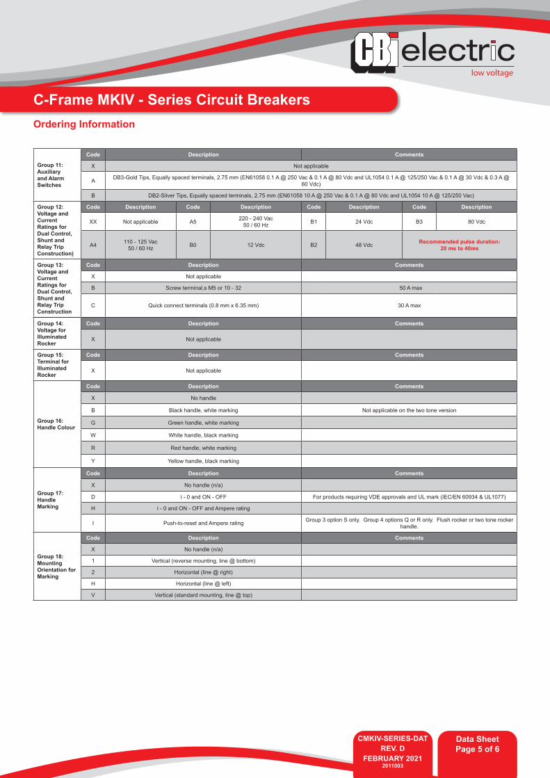
C-Frame MKIV - Series Circuit BreakersOrdering Information
Group 11: Auxiliary and Alarm Switches
Code Description Comments
X Not applicable
A DB3-Gold Tips, Equally spaced terminals, 2.75 mm (EN61058 0.1 A @ 250 Vac & 0.1 A @ 80 Vdc and UL1054 0.1 A @ 125/250 Vac & 0.1 A @ 30 Vdc & 0.3 A @ 60 Vdc)
B DB2-Silver Tips, Equally spaced terminals, 2.75 mm (EN61058 10 A @ 250 Vac & 0.1 A @ 80 Vdc and UL1054 10 A @ 125/250 Vac)
Group 12: Voltage and Current Ratings for Dual Control, Shunt and Relay Trip Construction)
Code Description Code Description Code Description Code Description
XX Not applicable A5 220 - 240 Vac50 / 60 Hz B1 24 Vdc B3 80 Vdc
A4 110 - 125 Vac50 / 60 Hz B0 12 Vdc B2 48 Vdc Recommended pulse duration:
20 ms to 40ms
Group 13: Voltage and Current Ratings for Dual Control, Shunt and Relay Trip Construction
Code Description Comments
X Not applicable
B Screw terminal,s M5 or 10 - 32 50 A max
C Quick connect terminals (0.8 mm x 6.35 mm) 30 A max
Group 14: Voltage for Illuminated Rocker
Code Description Comments
X Not applicable
Group 15: Terminal for Illuminated Rocker
Code Description Comments
X Not applicable
Group 16: Handle Colour
Code Description Comments
X No handle
B Black handle, white marking Not applicable on the two tone version
G Green handle, white marking
W White handle, black marking
R Red handle, white marking
Y Yellow handle, black marking
Group 17: Handle Marking
Code Description Comments
X No handle (n/a)
D I - 0 and ON - OFF For products requiring VDE approvals and UL mark (IEC/EN 60934 & UL1077)
H I - 0 and ON - OFF and Ampere rating
I Push-to-reset and Ampere rating Group 3 option S only. Group 4 options Q or R only. Flush rocker or two tone rocker handle.
Group 18: Mounting Orientation for Marking
Code Description Comments
X No handle (n/a)
1 Vertical (reverse mounting, line @ bottom)
2 Horizontal (line @ right)
H Horizontal (line @ left)
V Vertical (standard mounting, line @ top)
A member of the GroupCMKIV-SERIES-DATREV. D
FEBRUARY 20212011003
Data SheetPage 13 of 13
Please review our Customer Terms and Conditions on www.cbi-lowvoltage.co.zaAll rights reserved. Unless otherwise indicated, all materials on these pages are copyrighted by CBI (Pty) Ltd. No part of these pages, either text or image may be used for any purpose other than personal use. Therefore, reproduction, modification, storage in a retrieval system or retransmission, in any form or by any means, electronic, mechanical or otherwise, for reasons other than personal use, is strictly prohibited without prior written permission. CBI (Pty) Ltd reserves the right to alter any details of this document without notice and while every effort is made to ensure the accuracy of the content, no warranty is given as to the accuracy of this document and no responsibility will be accepted for error or misinterpretation and any resulting loss.
low voltage
Data SheetPage 6 of 6
© CBI (Pty) Ltd. All Rights Reserved.
AUSTRALIACBI-electric: Australia27 Wedgewood Rd, HallamVictoria 3803 AustraliaTel: +61 3 8752 9300Fax: +61 3 9796 5407Email: [email protected]: www.cbi-electric.com.au
SOUTH AFRICACBI-electric: low voltageTripswitch Drive ElandsfonteinGauteng South AfricaTel: +27 11 928 2000Fax: + 27 11 392 2354Email: [email protected] [email protected]: www.cbi-lowvoltage.com
USACBI-electric: North America35 E. Uwchlan Ave Suite 328Exton PA 19341 USATel: +1 610 524 9949Fax: +1 610 524 9945E-mail: [email protected]: www.cbibreakers.com
Group 19: Front Plate Marking and Test Button
Code Description Comments
2 No marking, with test button, rocker handle
B No marking, rocker handle
Group 20: Inter-phase Barrier and Terminal Cover
Code Description Comments
X Not applicable
A Small inter-phase barrier
C Z inter-phase barrier
Group 21: Approvals (Product Normally Approved to)
Code Description Comments
1 UL1077, IEC/EN 60934, CE
2 UL489, IEC/EN 60934, CE
3 UL489A, IEC/EN 60934, CE
Group 22: Safety Marks
Code Description Comments
X Not applicable
C GB17701 CCC
Ordering Information
C-Frame MKIV - Series Circuit Breakers
For options not listed, please contact CBI
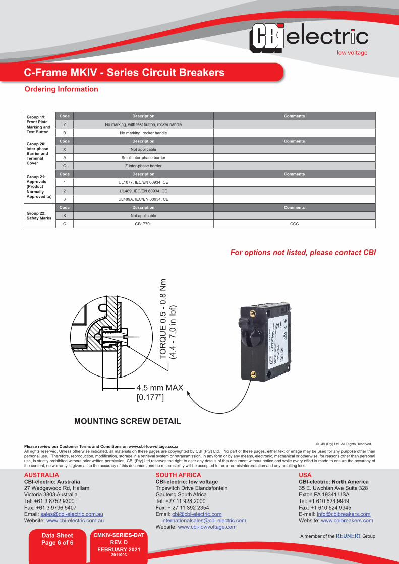
4.5 mm MAX[0.177”]
TOR
QU
E 0.
5 - 0
.8 N
m(4
.4 -
7.0
in lb
f)
MOUNTING SCREW DETAIL