c-channel
TRANSCRIPT


content346
IntroductIonIntroduction
Locations
8991011
GeneraL InformatIonmetal framing channels
channel Hole Patternsmaterials & finishes
channels Load & Support
1213161922252831343740434649
cHanneLSccH-220/221
ccH-222ccH-240/241
ccH-242ccH-320/321
ccH-322ccH-340/341
ccH-342ccH-420/421
ccH-422ccH-440/441
ccH-442toothed channel
5354
fIttInGSfittings
697071
SYStem examPLeSc-channel framing Systems 21x41c-channel framing Systems 41x41
63646566
cantILeverS & BeamScantilever arm Bracket - Sca
cantilever arm Bracket B2B - ScaSupport Sysytem
73747577798183
ancHorSGeneral Information
expansion Steel anchor -Stmdrop in anchor - SdaSleeve anchor - SaS
through Bolt (Wedge anchor) - StBShield anchor - SHa
5758606162
acceSSorIeSframing System accessories
channel nutsInstallation & features
Beam clamp - SBc
858688
converterS & termSconverters
terms
Specialized factory for Steel ProductsSIGma factory for Steel Products
ucm- unitech cable management
WWW.SfSP-Ikk.com
UNITECHfor Building & construction materialswww.unitech-ikk.com

IntroductIon
unI - cHanneL SYStemS SfSP
IntroductIon4
Specialized factory for Steel Products (Jeddah / kSa)Sigma factory, for Steel Products (ajman & umm al Quwain / uae)Specialized factory for Steel Products (6th of october / egypt)Specialized factory for Steel Products (tanayel / Lebanon)
SfSP metal framing system provides an economical solution for electrical, mechanical and industrial supports with a wide variety of applications in the construction industry.
this catalogue is designed to be helpful to engineers and contractors in the application and selection of channel products for construction and maintenance.If a unique application requires a special product not included in this catalogue , SfSP engineering personnel are ready to furnish design consultation and realistic cost estimates.
Metal FraMing / electrical applications• Pipe & conduit supports • Tunnel pipe stanchions• Beam attachments• Pipe risers
Metal FraMing / industrial applications
• Racks and shelvings• Production line supports• Trolley systems• Wall framings
unI - cHanneL SYStemSSfSP
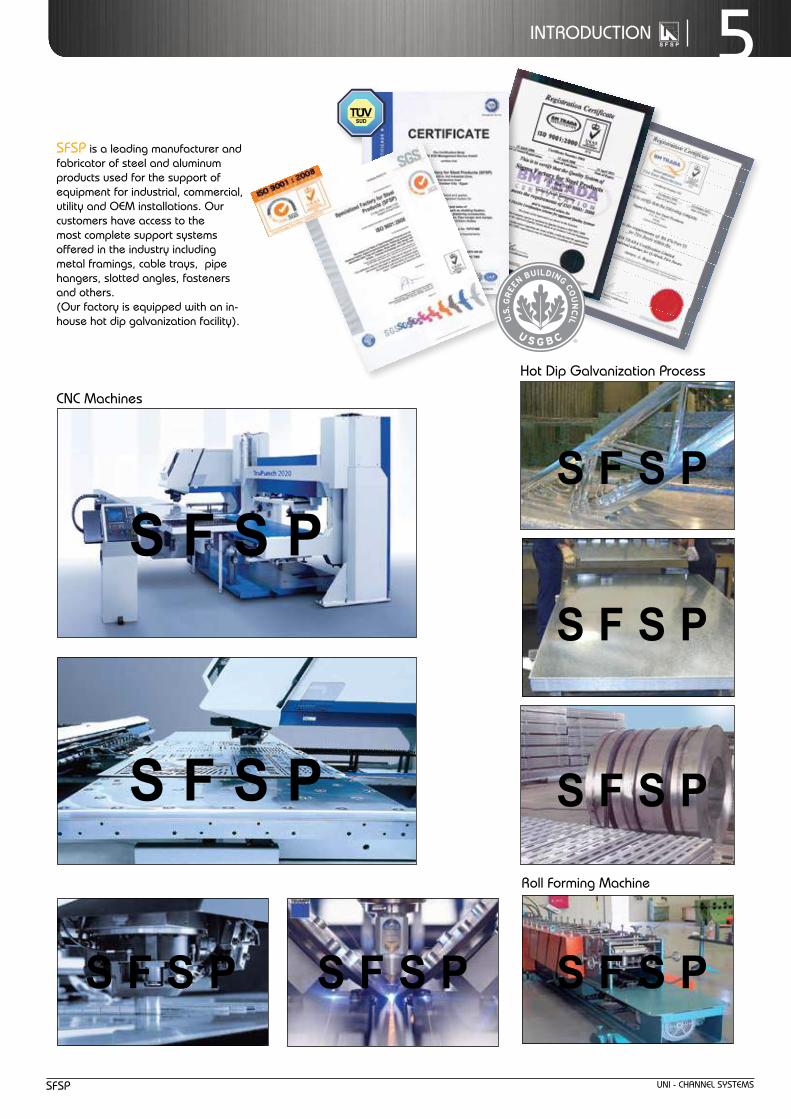
IntroductIon 5SfSP is a leading manufacturer and fabricator of steel and aluminum products used for the support of equipment for industrial, commercial, utility and oem installations. our customers have access to the most complete support systems offered in the industry including metal framings, cable trays, pipe hangers, slotted angles, fasteners and others.(our factory is equipped with an in-house hot dip galvanization facility).
cnc machines
roll forming machine
Hot dip Galvanization Process
Senegal
Kazakhstan
Spain
France
German yPoland
Greece
Albania
HungaryAustria
Slovakia
Czech RepUkraine
Maldova
Romania
Bulgaria
SerbiaCroatia
Italy
Turkey
Georgia
PortugalTurkmenistan
Afghanistan
Pakistan
India
Sri Lanka
Nepal
Uzbekistan
Tajikistan
Kyrgyzstan
IRAN
Tehran
Ashgabat
Kabol
EquatorialGuinea
Skakah
Gurayyat
Mak kahAl Taif
BeirutCyprus
SAUDI ARABIA
SYRIA
EGYPT
LEBANON
JORDAN
IRAQ
UAE
BAHRAIN
Najran
Khamis Mushayt
Riyadh
Hail Qassim
Yanbu
Jeddah
Dammam Manama
JubailHafr Al Batin
Gizan
Baha
Ma dinah
Hufuf
Cairo
YEMEN
SUDANChad
Niger
Aqaba
Al Kharj
Amman
Ajman
6th of October
Jebel Ali
Doha
QATAR
TabukLIBYAALGERIA
TUNISIA
Malta
MOROCCO
OMAN
KUWAIT
Tripoli Banghazi
AlgeriaOranTanger
Casablank a
Muscat
Sanaa’
Adan
Khartoum
Salalah
Erbi l
Baku
DubaiSharjah
U A Q
Libreville
Nigeria
Cameroon
DR Congo
Zambia MalawiAngola
Botswana
Zimbabw e
Mozambique
Gabon Congo
Ethiopia
Djipouti
UgandaKenya
Eritre a
Somalia
Muqdisho
CentralAfrican
Republic
UnitedRepublic of
Tanzania
WindhoekNamibia
Bata
Mali
Burkina Faso
GhanaCote
d’lvoire
Guinea
Mauritania
Benin
Abuja
Stuttgar tAstana
Luanda
Gaborone
Norway
Ireland
Sweden
Finland
Denmark
Netherlands
Switzerland
Belgium
Finland
Estonia
Latvia
Lithuania
Azerbaija nArmenia
Belarus
Istanbul
UK
Purchasing & Supply
Up-Coming Branch
Up-Coming Factory
Design Office
Factory
Branch
Main Branch
Managing Office
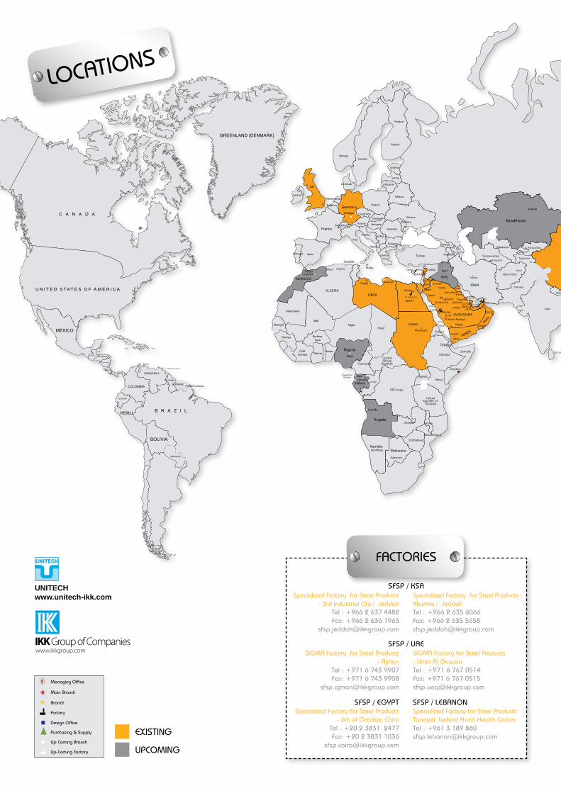
LOCATIONS
SFSP / EGYPTSpecialized Factory for Steel Products
- 6th of October, Cairo T 7742 1383 2 02+ : leFax: +20 2 3831 1036
SFSP / LEBANONSpecialized Factory for Steel ProductsTanayel ,behind Hariri Health CenterTel : +961 3 189 860 [email protected]
SIGMA Factory for Steel Products - Ajman
T 7099 347 6 179+ : leFax: +971 6 743 9908
SIGMA Factory for Steel Products - Umm Al QuwainTel : +971 6 767 0514Fax: +971 6 767 [email protected]
SFSP / UAE
Specialized Factory for Steel Products - 3rd Industrial City / Jeddah
T 2844 736 2 669+ : leF 3691 636 2 669+ :xa
Specialized Factory for Steel Products - Khumra / JeddahTel : +966 2 635 6066 Fax: +966 2 635 5658 [email protected]
SFSP / KSA
FACTORIES
EXISTING
UPCOMING
UNITECHwww.unitech-ikk.com

Russia
Sri Lanka
TaiwanBangladesh
China
Myanmar
Thailand
Laos
NepalYiwu
Australia
New Zealand
Japan
Korea
Mongolia
Vietnam
Hatyai
Cambodia
Malaysia
Indonesia
New Guinea
Philippines
Sydney
KSA NATIONAL TOLL FREE NUMBER: 800 119 1190
Jeddah / ksa Tel : +966 2 627 8222Fax: +966 2 627 8722
Jeddah - Ghurab Showroom / KSA
Tel : +966 2 667 2000Fax: +966 2 661 4306
Mak kah, Taif / KSATel : +966 2 597 2675Fax: +966 2 597 0588
Qassim Showroom / ksaTel : +966 6 385 2598Fax: +966 6 382 6684
Tabuk / ksaTel : +966 4 424 3386Fax: +966 4 423 5203
Skakah / Qurayyat / ksaTel : +966 4 626 3904Fax: +966 4 626 3905
Hail / ksaTel : +966 6 543 3931Fax: +966 6 543 3935
Dammam / ksaTel : +966 3 859 0097Fax: +966 3 857 8177
Dammam / Showroom / ksaTel : +966 3 834 9300Fax: +966 3 834 9457
Hufuf / ksaTel : +966 3 586 9732Fax: +966 3 584 5966
Jubail / ksaTel : +966 3 361 4390Fax: +966 3 361 4499
Manama / Bahrain Tel : +973 1 756 4386Fax: +973 1 756 4315
Dubai - DIP / UAETel : +971 4 884 7275Fax: +971 4 884 7278
Dubai - Barsha / UAETel : +971 4 427 9500Fax : +971 4 427 9501
Dubai - Al Rashidiyah / UAETel : +971 4 285 6031Fax : +971 4 286 2941
Abu Dhabi - Musaffah / UAETel : +971 2 551 2334Fax: +971 2 551 2335
Doha / QatarTel : +974 4451 3301/2/3Fax: +974 4451 [email protected]
Beirut / LebanonTel : +961 1 858 277Fax: +961 1 858 [email protected]
Amman / JordanTel : +962 6 556 3030Fax: +962 6 554 [email protected]
Muscat / OmanTel : + 968 2459 1006Fax : + 968 2459 [email protected]
Cairo - Muhandiseen / EgyptTel : +20 2 3304 3091Tel : +20 2 3346 8566Fax: +20 2 3346 [email protected]
Cairo - Gamhouriyah St. / EgyptTel: +20 2 2787 2152Fax: +20 2 2593 [email protected]
Kuwait City / KuwaitTel : +965 22 459 984Fax: +965 22 459 [email protected]
Sana’a / Yemen Tel : +967 1 473 542Fax: +967 1 473 [email protected]
Mad inah / ksaTel : +966 4 864 9111Fax: +966 4 864 [email protected]
Mad inah Showroom - UPF / ksaTel : +966 4 834 6244Fax: +966 4 834 5082
Yanbu / ksaTel : +966 4 390 1499Fax: +966 4 322 [email protected]
Khamis Mushayt / ksaTel : +966 7 237 5929Fax: +966 7 237 8783 [email protected]
Najran / ksaTel : +966 7 321 4038Fax: +966 7 321 [email protected]
Gizan / ksaTel : +966 7 321 6660Fax: +966 7 321 [email protected]
Riyadh / ksaTel : +966 1 454 9282Fax: +966 1 456 [email protected]
Riyadh - Rail St.Office / ksaTel : +966 1 810 5926Fax: +966 1 456 [email protected]
Qassim / ksaTel : +966 6 382 3946Fax: +966 6 385 [email protected]
SALES OPERATIONS
LEBANON Multi-D Beirut Tel : +961 1 841 155fax: +961 1 841 [email protected]
GERMANYUNITECH Stuttgart
Tel : +49 711 6868 7222 Fax: +49 711 6868 7223
KSACPU Jeddah
Tel : + 966 2 627 8 275Fax: +966 2 627 8 727
UAETOSL Jebel AliTel : +971 4 886 0262Fax: +971 4 886 [email protected]
CHINAUNITECH Yiwu - Zhejiang Province
Tel : +86 579 8545 3180Fax: +86 579 8542 7682
DESIGN, LOGISTICS, MATERIALS, MEDIA, R&D

GeneraL InformatIon

unI - cHanneL SYStemSSfSP
9GeneraL InformatIon
Z
Z
YY
Z
Z
YY
Z
Z
YY
Z
Z
Y Y
21.0
7.0
41.0
21.0
41.0
22.0
42.0
7.0
41.0
22.0
41.0
7.0
41.0
41.0
41.0
22.0
82.0
7.0
41.0
22.0
50
30
13
Z
Z
YY
Z
Z
YY
Z
Z
YY
Z
Z
Y Y
21.0
7.0
41.0
21.0
41.0
22.0
42.0
7.0
41.0
22.0
41.0
7.0
41.0
41.0
41.0
22.0
82.0
7.0
41.0
22.0
50
30
13
Z
Z
YY
Z
Z
YY
Z
Z
YY
Z
Z
Y Y
21.0
7.0
41.0
21.0
41.0
22.0
42.0
7.0
41.0
22.0
41.0
7.0
41.0
41.0
41.0
22.0
82.0
7.0
41.0
22.0
50
30
13
Z
Z
YY
Z
Z
YY
Z
Z
YY
Z
Z
Y Y
21.0
7.0
41.0
21.0
41.0
22.0
42.0
7.0
41.0
22.0
41.0
7.0
41.0
41.0
41.0
22.0
82.0
7.0
41.0
22.0
50
30
13
Z
Z
YY
Z
Z
YY
Z
Z
YY
Z
Z
Y Y
21.0
7.0
41.0
21.0
41.0
22.0
42.0
7.0
41.0
22.0
41.0
7.0
41.0
41.0
41.0
22.0
82.0
7.0
41.0
22.0
50
30
13
cHanneL HoLe PatternS
metaL framInG cHanneLS
Pt Plain type St Slotted type B2B type toothed channel type
Selection chart
Pt type channel St type channel B2B type channel
Part no channel dimensions thickness
Height “H” Width “W”
ccH - 220/221 21.0 mm 41.0 mm 1.5 mm
ccH - 240/241 41.0 mm 41.0 mm 1.5 mm
ccH - 320/321 21.0 mm 41.0 mm 2.0 mm
ccH - 340/341 41.0 mm 41.0 mm 2.0 mm
ccH - 420/421 21.0 mm 41.0 mm 2.5 mm
ccH - 440/441 41.0 mm 41.0 mm 2.5 mm
Part no thick. mm.
Height “H”
ccH-220 1.5 21.0
ccH-240 1.5 41.0
ccH-320 2.0 21.0
ccH-340 2.0 41.0
ccH-420 2.5 21.0
ccH-440 2.5 41.0
Part no thick. mm.
Height “H”
ccH-221 1.5 21.0
ccH-241 1.5 41.0
ccH-321 2.0 21.0
ccH-341 2.0 41.0
ccH-421 2.5 21.0
ccH-441 2.5 41.0
Part no thick. mm.
Height “H”
ccH-222 1.5 42.0
ccH-242 1.5 82.0
ccH-322 2.0 42.0
ccH-342 2.0 82.0
ccH-422 2.5 42.0
ccH-442 2.5 82.0
CCH 320 3 2 0
channel Patterns0 - Pt 1 - St2 - B2B
toothed channel
Size2 - 21/41 mm 4 - 41/41 mm
material thickness2 for 1.5 mm3 for 2.0 mm 4 for 2.5 mm
channelSfSP’s metal framing channel is cold formed on modern rolling machines from low carbon steel manufactured according to BS 6946:1988. a continuous slot provides the ability to make attachments at any point.
LengthsStandard length: 3000mm with ± 3.2mm length tolerance.custom lengths are available upon request.
finishesStandard finishes: Pre-Galvanized finish (aStm a653m coating G90 and G60). Hot dip Galvanized after fabrication (aStm a123 or BS en ISo1461:2009) . other custom coatings are available upon request.
for toothed channel add “t” after the Part no. ex: ccH-220t
for toothed channel add “t” after the Part no. ex: ccH-220t
t

unI - cHanneL SYStemS SfSP
10 GeneraL InformatIon
mild Steel - Plaina. Hot rolled Steel Plates, Sheets and coils S235 Jr, S355 Jr,as per:en 10025 -2 / dIn 17100 / BS 4360 / aStm a 1011/ aStm a 1011-01a JIS 3101 / JIS 3106 / GB 700 / GB / t1591.aStm a 907 / aStm a 1018m.aStm a 570m / aStm a 572m.B. cold rolled Steel dc 01,as per:en 10130 / dIn 1623, Part 2 / BS 1449:1 / aStm a366 / aStm a 1008 / JIS G 3141 / GB 699.en 10131 / aStm a 568m
mild Steel - Galvanized c. continuously Pre- Galvanized Hot–dip Zinc coated Steel dx 51d + Z,as per: en 10327 / dIn 17162 / BS 2989/ aStm a 527m / aStm a 653m / JIS G 3302.en 10346 / en 10326 / en 10142 / aStm a 526, 527, 528
d. electro Galvanized Steel (electrolytic coating) dc01 + Ze,as per: en 10152 / dIn 17163 / aStm a591 / JIS G 3313 / JIS G 3141/BS 1449:1en 10131
aluZink Steele.aluZink Steel dx 51d + aZ,ِas per: en 10215 / en 10143/ dIn 55928 / aStm a 792
Stainless Steelf.austenitic Stainless Steels aISI 304 & 316, as per: aStm a 240 /en 10088-2/ dIn 17400 / BS 1449:2 / aStm a480 / aStm a666 / ISo 3506 / en 10028-7 /JIS G 4304f.1 Stainless Steel fasteners en 3506f.2 Stainless Steel Wire BS 1554 ,aStm a276
aluminiumG.aluminium 5052 & 6063
fIn
ISH
eS
1- Hot–dIP Galvanization after fabrication, as per:aStm a 123 / aStm a 153 / ISo 1461.BS 729 / dIn 50976
2- Zinc electroplating after fabrication,as per:aStm B633 / en 2081 / en 12329 / ISo 4042/ BS 1706 / BS 7371-12 / BS 3382 / dIn 50961
3- Powder coatingepoxy / Polyester / epoxy & PolyesterBS 3900 / ISo 2409 / ISo 1519 / ISo 1520
mat
erIa
LS

unI - cHanneL SYStemSSfSP
11GeneraL InformatIon
Load and Support condition Load factor deflection factor
Simple Beam - concentrated Load at center 1.00 0.80
Simple Beam -two equal concentrated Loads at 1/4 Points 2 x 1.00 1.10
Beam fixed at Both ends - concentrated Load at center 2.00 0.40
cantilever Beam - uniform Load 0.24 3.20
continuous Beam - two equal Spans -concentrated Load at center of one Span
1.42 0.80
continuous Beam - two equal Spans-concentrated Load at center of Both Spans
2 x 1.34 0.50
Load and Support condition Load factor deflection factor
Simple Beam - uniform Load 1.00 1.00
Beam fixed at Both ends - uniform Load 1.50 0.30
cantilever Beam - uniform Load 0.25 2.40
continuous Beam - two equalSpans - uniform Load on one Span
1.30 0.92
continuous Beam - two equal Spans- concentrated Load on Both Spans
1.00 0.42
q
Problem Item Solution
calculate the maximum allowable load and corresponding deflection of a cantilever ccH beam with a uniformly distributed load
from beam load chart for ccH , maximum allowable load is q and the corresponding deflection is u. multiplying by the appropriate factors shown in the chart above.
Load = q x load factor
defLectIon = u x deflection factor
q
ex
am
PL
e
F
Problem Item Solution
calculate the maximum allowable load and corresponding deflection of a simply supported ccH beam with a concentrated load at midspan as shown
from beam load chart for ccH , maximum allowable load is F and the corresponding deflection is u. multiplying by the appropriate factors shown in the chart above.
Load = F x load factor
defLectIon = u x deflection factorex
am
PL
e
tecHnIcaL data
F F
F
span
span span
span
q

cHanneLS
unI - cHanneL SYStemSSfSP
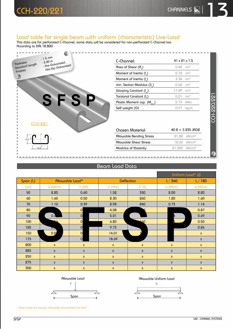
13cHanneLSccH-220/221
Load table for single beam with uniform (characteristic) Live-Loadthis data are for perforated c-channel, same data will be considered for non-perforated c-channel tooaccording to dIn 18.800
* Given loads are always “allowable characteristic live load”
Chosen Material:Allowable Bending Stress 21,82 kN/cm²Allowable Shear Stress 12,60 kN/cm²Modulus of Elasticity 21.000 kN/cm²
40B = S 235 JRG2
C-Channel:Area of Shear (Az)
1,67 cm
Moment of Inertia (Iy)
5,87 cm
Moment of Inertia (Iz
y
z
)
8,76 cm
min. Section Modulus (Sy)
2,72 cm
Warping Constant (Iw)
171,52 cm
Torsional Constant (IT)
0,07 cm
Plastic Moment cap. (Mpl,y)
0,82 kNm
Self weight (G)
2,32 kg/m
C 41x41x2,52
4
4
3
6
4
cmcmcmcmcmcmkNmkg/m
2
4
4
3
6
4
C-Channel:Cross Section Area (A) cm2
Moment of Inertia (I ) cm4
4Moment of Inertia (I ) cmSelf Weight (G) kg/m
^
allowable Load
Span
f
Chosen Material:Allowable Bending Stress 21,82 kN/cm²Allowable Shear Stress 12,60 kN/cm²Modulus of Elasticity 21.000 kN/cm²
40B = S 235 JRG2
C-Channel:Area of Shear (Az)
1,67 cm
Moment of Inertia (Iy)
5,87 cm
Moment of Inertia (Iz
y
z
)
8,76 cm
min. Section Modulus (Sy)
2,72 cm
Warping Constant (Iw)
171,52 cm
Torsional Constant (IT)
0,07 cm
Plastic Moment cap. (Mpl,y)
0,82 kNm
Self weight (G)
2,32 kg/m
C 41x41x2,52
4
4
3
6
4
cmcmcmcmcmcmkNmkg/m
2
4
4
3
6
4
C-Channel:Cross Section Area (A) cm2
Moment of Inertia (I ) cm4
4Moment of Inertia (I ) cmSelf Weight (G) kg/m
^
allowable uniform Load
Span
q
Beam Load data
ccH
-220
/221
Z
Z
YY
Z
Z
YY
Z
Z
YY
Z
Z
Y Y
21.0
7.0
41.0
21.0
41.0
22.0
42.0
7.0
41.0
22.0
41.0
7.0
41.0
41.0
41.0
22.0
82.0
7.0
41.0
22.0
50
30
13
c-channel: 41 x 21 x 1.5
area of Shear (az) 0.42 cm2
moment of Inertia (Iy) 0.70 cm4
moment of Inertia (Iz) 3.34 cm4
min. Section modulus (Sy) 0.60 cm3
Warping constant (Iw) 17.49 cm6
torsional constant (It) 0.01 cm4
Plastic moment cap. (mpl,y) 0.19 knm
Self weight (G) 0.97 kg/m
chosen material: 40 B = S 235 JrG2
allowable Bending Stress 21,82 kn/cm2
allowable Shear Stress 12,60 kn/cm2
modulus of elasticity 21.000 kn/cm2
uniform Load* @
Span (L) allowable Load* deflection L / 360 L / 180[cm] q [kn/m] f [kn] u [mm] [L /x] q [kn/m] q [kn/m]
50 2.20 0.60 1.52 330 2.00 2.20
60 1.60 0.50 2.30 260 1.20 1.60
70 1.10 0.39 2.92 240 0.73 1.14
80 0.90 0.36 4.08 200 0.49 0.87
90 0.69 0.31 5.01 180 0.34 0.69
100 0.56 0.28 6.20 160 0.25 0.50
125 0.36 0.23 9.73 130 x 0.26
150 0.25 0.19 14.01 110 x x
175 0.18 0.16 18.69 90 x x
200 x x x x x x
225 x x x x x x
250 x x x x x x
275 x x x x x x
300 x x x x x x
thickness : 1.5 mm
Standard Length : 3.00 m
finishes : Pre-Galvanized,
Hot-dip Galvanized.
ccH-221

unI - cHanneL SYStemS SfSP
14 cHanneLS ccH-220/221
Beam LoadInG GraPH ccH-220/221
2.00
1.50
2.50
0.00
0.50
1.00
50 60 70 80 90 100 125 150 175 200 225 250 275 300
12.00 14.00 16.00 18.00 20.00
0.00 2.00 4.00 6.00 8.00
10.00
50 60 70 80 90 100 125 150 175 200 225 250 275 300
0.60 0.70 0.80 0.90 1.00
0.00 0.10 0.20 0.30 0.40 0.50
80 90 100 125 150 175 200 225 250 275 300
allowable Loads
deflection @ allowable uniform Load
uniform Load @ allowable deflection
[Span] cm
[Span] cm
Chosen Material:Allowable Bending Stress 21,82 kN/cm²Allowable Shear Stress 12,60 kN/cm²Modulus of Elasticity 21.000 kN/cm²
40B = S 235 JRG2
C-Channel:Area of Shear (Az)
1,67 cm
Moment of Inertia (Iy)
5,87 cm
Moment of Inertia (Iz
y
z
)
8,76 cm
min. Section Modulus (Sy)
2,72 cm
Warping Constant (Iw)
171,52 cm
Torsional Constant (IT)
0,07 cm
Plastic Moment cap. (Mpl,y)
0,82 kNm
Self weight (G)
2,32 kg/m
C 41x41x2,52
4
4
3
6
4
cmcmcmcmcmcmkNmkg/m
2
4
4
3
6
4
C-Channel:Cross Section Area (A) cm2
Moment of Inertia (I ) cm4
4Moment of Inertia (I ) cmSelf Weight (G) kg/m
^
f
q [kn/m]
f [kn]
q
mm
kn/m
[Span] cm
L /180
Chosen Material:Allowable Bending Stress 21,82 kN/cm²Allowable Shear Stress 12,60 kN/cm²Modulus of Elasticity 21.000 kN/cm²
40B = S 235 JRG2
C-Channel:Area of Shear (Az)
1,67 cm
Moment of Inertia (Iy)
5,87 cm
Moment of Inertia (Iz
y
z
)
8,76 cm
min. Section Modulus (Sy)
2,72 cm
Warping Constant (Iw)
171,52 cm
Torsional Constant (IT)
0,07 cm
Plastic Moment cap. (Mpl,y)
0,82 kNm
Self weight (G)
2,32 kg/m
C 41x41x2,52
4
4
3
6
4
cmcmcmcmcmcmkNmkg/m
2
4
4
3
6
4
C-Channel:Cross Section Area (A) cm2
Moment of Inertia (I ) cm4
4Moment of Inertia (I ) cmSelf Weight (G) kg/m
^
L /360
Chosen Material:Allowable Bending Stress 21,82 kN/cm²Allowable Shear Stress 12,60 kN/cm²Modulus of Elasticity 21.000 kN/cm²
40B = S 235 JRG2
C-Channel:Area of Shear (Az)
1,67 cm
Moment of Inertia (Iy)
5,87 cm
Moment of Inertia (Iz
y
z
)
8,76 cm
min. Section Modulus (Sy)
2,72 cm
Warping Constant (Iw)
171,52 cm
Torsional Constant (IT)
0,07 cm
Plastic Moment cap. (Mpl,y)
0,82 kNm
Self weight (G)
2,32 kg/m
C 41x41x2,52
4
4
3
6
4
cmcmcmcmcmcmkNmkg/m
2
4
4
3
6
4
C-Channel:Cross Section Area (A) cm2
Moment of Inertia (I ) cm4
4Moment of Inertia (I ) cmSelf Weight (G) kg/m
^
L /180
q [kn/m]
L /360
q [kn/m]
kn/m
... k
n
Chosen Material:Allowable Bending Stress 21,82 kN/cm²Allowable Shear Stress 12,60 kN/cm²Modulus of Elasticity 21.000 kN/cm²
40B = S 235 JRG2
C-Channel:Area of Shear (Az)
1,67 cm
Moment of Inertia (Iy)
5,87 cm
Moment of Inertia (Iz
y
z
)
8,76 cm
min. Section Modulus (Sy)
2,72 cm
Warping Constant (Iw)
171,52 cm
Torsional Constant (IT)
0,07 cm
Plastic Moment cap. (Mpl,y)
0,82 kNm
Self weight (G)
2,32 kg/m
C 41x41x2,52
4
4
3
6
4
cmcmcmcmcmcmkNmkg/m
2
4
4
3
6
4
C-Channel:Cross Section Area (A) cm2
Moment of Inertia (I ) cm4
4Moment of Inertia (I ) cmSelf Weight (G) kg/m
^
u
q [kn/m]
q

unI - cHanneL SYStemSSfSP
15cHanneLSccH-220/221
Load table for single beam with uniform (characteristic) Live-Loadthis data are for perforated c-channel, same data will be considered for non-perforated c-channel tooaccording to dIn 18.800
allo
wab
le c
entr
al L
oad*
*cc
H-2
20/2
21co
lum
n Lo
ad d
ata
** Given loads are always “allowable characteristic live load”
Z
Z
YY
Z
Z
YY
Z
Z
YY
Z
Z
Y Y
21.0
7.0
41.0
21.0
41.0
22.0
42.0
7.0
41.0
22.0
41.0
7.0
41.0
41.0
41.0
22.0
82.0
7.0
41.0
22.0
50
30
13
6.00
5.00
7.00
8.00
9.00
0.00
1.00
2.00
3.00
4.00
50 60 70 80 90 100 125 150 175 200 225 250 275 300
kn
[Length]cm
c-channel: 41 x 21 x 1.5
cross Section area (a) 0.23 cm2
moment of Inertia (Iy) 0.70 cm4
moment of Inertia (Iz) 3.34 cm4
Self weight (G) 0.97 kg/m
allowable uniform Load
ACase:
Length
B C D
Leng
th
Span (L) allowable central Load** [kn][cm] case a case B case c case d
50 8.00 8.00 8.00 5.00
60 8.00 8.00 8.00 4.10
70 8.00 8.00 8.00 3.20
80 7.00 8.00 8.00 2.50
90 6.00 8.00 8.00 2.00
100 5.00 8.00 8.00 1.70
125 3.80 6.00 8.00 1.70
150 2.80 5.00 8.00 1.10
175 2.10 4.00 6.00 x
200 1.70 3.20 5.00 x
225 1.40 2.60 4.60 x
250 1.10 2.10 3.80 x
275 x 1.80 3.30 x
300 x 1.50 2.80 x
case a
case B
case ccase d

unI - cHanneL SYStemS SfSP
16 cHanneLS
Load table for single beam with uniform (characteristic) Live-Loadthis data are for perforated c-channel, same data will be considered for non-perforated c-channel tooaccording to dIn 18.800
ccH-222
c-channel: 41x 21x1.5 b2b
area of Shear (az) 0.54 cm2
moment of Inertia (Iy) 3.55 cm4
moment of Inertia (Iz) 6.69 cm4
min. Section modulus (Sy) 1.69 cm3
Warping constant (Iw) 16.33 cm6
torsional constant (It) 0.03 cm4
Plastic moment cap. (mpl,y) 0.50 knm
Self weight (G) 1.94 kg/m
chosen material: 40 B = S 235 JrG2
allowable Bending Stress 21,82 kn/cm2
allowable Shear Stress 12,60 kn/cm2
modulus of elasticity 21.000 kn/cm2
Z
Z
YY
Z
Z
YY
Z
Z
YY
Z
Z
Y Y
21.0
7.0
41.0
21.0
41.0
22.0
42.0
7.0
41.0
22.0
41.0
7.0
41.0
41.0
41.0
22.0
82.0
7.0
41.0
22.0
50
30
13
ccH-222
* Given loads are always “allowable characteristic live load”
Beam Load datauniform Load* @
Span (L) allowable Load* deflection L / 360 L / 180[cm] q [kn/m] f [kn] u [mm] [L /x] q [kn/m] q [kn/m]
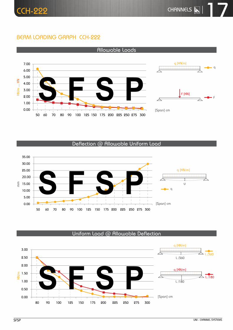
50 6.30 1.60 0.86 580 6.30 6.30
60 4.40 1.30 1.24 480 4.40 4.40
70 3.20 1.10 1.68 420 3.20 3.20
80 2.50 1.00 2.24 360 2.50 2.50
90 1.90 0.90 2.72 330 1.70 1.90
100 1.60 0.80 3.49 290 1.30 1.60
125 1.00 0.60 5.33 230 0.70 1.00
150 0.70 0.50 7.74 190 0.40 0.70
175 0.51 0.40 10.44 170 0.20 0.50
200 0.39 0.39 13.62 150 x 0.32
225 0.31 0.35 17.35 130 x 0.22
250 0.25 0.31 21.32 120 x 0.16
275 0.21 0.29 26.22 100 x x
300 0.17 0.26 30.06 100 x x
Chosen Material:Allowable Bending Stress 21,82 kN/cm²Allowable Shear Stress 12,60 kN/cm²Modulus of Elasticity 21.000 kN/cm²
40B = S 235 JRG2
C-Channel:Area of Shear (Az)
1,67 cm
Moment of Inertia (Iy)
5,87 cm
Moment of Inertia (Iz
y
z
)
8,76 cm
min. Section Modulus (Sy)
2,72 cm
Warping Constant (Iw)
171,52 cm
Torsional Constant (IT)
0,07 cm
Plastic Moment cap. (Mpl,y)
0,82 kNm
Self weight (G)
2,32 kg/m
C 41x41x2,52
4
4
3
6
4
cmcmcmcmcmcmkNmkg/m
2
4
4
3
6
4
C-Channel:Cross Section Area (A) cm2
Moment of Inertia (I ) cm4
4Moment of Inertia (I ) cmSelf Weight (G) kg/m
^
allowable Load
Span
f
Chosen Material:Allowable Bending Stress 21,82 kN/cm²Allowable Shear Stress 12,60 kN/cm²Modulus of Elasticity 21.000 kN/cm²
40B = S 235 JRG2
C-Channel:Area of Shear (Az)
1,67 cm
Moment of Inertia (Iy)
5,87 cm
Moment of Inertia (Iz
y
z
)
8,76 cm
min. Section Modulus (Sy)
2,72 cm
Warping Constant (Iw)
171,52 cm
Torsional Constant (IT)
0,07 cm
Plastic Moment cap. (Mpl,y)
0,82 kNm
Self weight (G)
2,32 kg/m
C 41x41x2,52
4
4
3
6
4
cmcmcmcmcmcmkNmkg/m
2
4
4
3
6
4
C-Channel:Cross Section Area (A) cm2
Moment of Inertia (I ) cm4
4Moment of Inertia (I ) cmSelf Weight (G) kg/m
^
allowable uniform Load
Span
q
ccH
-222
thickness : 1.5 mmStandard Length : 3.00 m
finishes : Pre-Galvanized,
Hot-dip Galvanized.
unI - cHanneL SYStemSSfSP
17cHanneLSccH-222
25.00
20.00
30.00
35.00
0.00
5.00
10.00
15.00
50 60 70 80 90 100 125 150 175 200 225 250 275 300
[Span] cm
mm
[Span] cm
[Span] cm
5.00
6.00
7.00
0.00
1.00
2.00
3.00
4.00
50 60 70 80 90 100 125 150 175 200 225 250 275 300
kn/m
... k
n
2.00
2.50
3.00
0.00
0.50
1.00
1.50
80 90 100 125 150 175 200 225 250 275 300
kn/m
Beam LoadInG GraPH ccH-222
allowable Loads
deflection @ allowable uniform Load
uniform Load @ allowable deflection
Chosen Material:Allowable Bending Stress 21,82 kN/cm²Allowable Shear Stress 12,60 kN/cm²Modulus of Elasticity 21.000 kN/cm²
40B = S 235 JRG2
C-Channel:Area of Shear (Az)
1,67 cm
Moment of Inertia (Iy)
5,87 cm
Moment of Inertia (Iz
y
z
)
8,76 cm
min. Section Modulus (Sy)
2,72 cm
Warping Constant (Iw)
171,52 cm
Torsional Constant (IT)
0,07 cm
Plastic Moment cap. (Mpl,y)
0,82 kNm
Self weight (G)
2,32 kg/m
C 41x41x2,52
4
4
3
6
4
cmcmcmcmcmcmkNmkg/m
2
4
4
3
6
4
C-Channel:Cross Section Area (A) cm2
Moment of Inertia (I ) cm4
4Moment of Inertia (I ) cmSelf Weight (G) kg/m
^
f
q [kn/m]
f [kn]
q
L /180
Chosen Material:Allowable Bending Stress 21,82 kN/cm²Allowable Shear Stress 12,60 kN/cm²Modulus of Elasticity 21.000 kN/cm²
40B = S 235 JRG2
C-Channel:Area of Shear (Az)
1,67 cm
Moment of Inertia (Iy)
5,87 cm
Moment of Inertia (Iz
y
z
)
8,76 cm
min. Section Modulus (Sy)
2,72 cm
Warping Constant (Iw)
171,52 cm
Torsional Constant (IT)
0,07 cm
Plastic Moment cap. (Mpl,y)
0,82 kNm
Self weight (G)
2,32 kg/m
C 41x41x2,52
4
4
3
6
4
cmcmcmcmcmcmkNmkg/m
2
4
4
3
6
4
C-Channel:Cross Section Area (A) cm2
Moment of Inertia (I ) cm4
4Moment of Inertia (I ) cmSelf Weight (G) kg/m
^
L /360
Chosen Material:Allowable Bending Stress 21,82 kN/cm²Allowable Shear Stress 12,60 kN/cm²Modulus of Elasticity 21.000 kN/cm²
40B = S 235 JRG2
C-Channel:Area of Shear (Az)
1,67 cm
Moment of Inertia (Iy)
5,87 cm
Moment of Inertia (Iz
y
z
)
8,76 cm
min. Section Modulus (Sy)
2,72 cm
Warping Constant (Iw)
171,52 cm
Torsional Constant (IT)
0,07 cm
Plastic Moment cap. (Mpl,y)
0,82 kNm
Self weight (G)
2,32 kg/m
C 41x41x2,52
4
4
3
6
4
cmcmcmcmcmcmkNmkg/m
2
4
4
3
6
4
C-Channel:Cross Section Area (A) cm2
Moment of Inertia (I ) cm4
4Moment of Inertia (I ) cmSelf Weight (G) kg/m
^
L /180
q [kn/m]
L /360
q [kn/m]
Chosen Material:Allowable Bending Stress 21,82 kN/cm²Allowable Shear Stress 12,60 kN/cm²Modulus of Elasticity 21.000 kN/cm²
40B = S 235 JRG2
C-Channel:Area of Shear (Az)
1,67 cm
Moment of Inertia (Iy)
5,87 cm
Moment of Inertia (Iz
y
z
)
8,76 cm
min. Section Modulus (Sy)
2,72 cm
Warping Constant (Iw)
171,52 cm
Torsional Constant (IT)
0,07 cm
Plastic Moment cap. (Mpl,y)
0,82 kNm
Self weight (G)
2,32 kg/m
C 41x41x2,52
4
4
3
6
4
cmcmcmcmcmcmkNmkg/m
2
4
4
3
6
4
C-Channel:Cross Section Area (A) cm2
Moment of Inertia (I ) cm4
4Moment of Inertia (I ) cmSelf Weight (G) kg/m
^
u
q [kn/m]
q

unI - cHanneL SYStemS SfSP
18 cHanneLS
Load table for single beam with uniform (characteristic) Live-Loadthis data are for perforated c-channel, same data will be considered for non-perforated c-channel tooaccording to dIn 18.800
allo
wab
le c
entr
al L
oad*
*cc
H-2
22
colu
mn
Load
dat
accH-222
Z
Z
YY
Z
Z
YY
Z
Z
YY
Z
Z
Y Y
21.0
7.0
41.0
21.0
41.0
22.0
42.0
7.0
41.0
22.0
41.0
7.0
41.0
41.0
41.0
22.0
82.0
7.0
41.0
22.0
50
30
13
** Given loads are always “allowable characteristic live load”
allowable uniform Load
ACase:
Length
B C D
Leng
th
c-channel: 41 x 21 x 1.5 b2b
cross Section area (a) 2.47 cm2
moment of Inertia (Iy) 3.55 cm4
moment of Inertia (Iz) 6.69 cm4
Self weight (G) 1.94 kg/m
Span (L) allowable central Load** [kn][cm] case a case B case c case d
50 16.00 16.00 16.00 16.00
60 16.00 16.00 16.00 16.00
70 16.00 16.00 16.00 13.00
80 16.00 16.00 16.00 10.00
90 16.00 16.00 16.00 9.00
100 16.00 16.00 16.00 7.00
125 15.00 16.00 16.00 5.00
150 11.00 16.00 16.00 3.70
175 9.00 15.00 16.00 2.80
200 7.00 13.00 16.00 2.20
225 6.00 11.00 16.00 x
250 5.00 9.00 15.00 x
275 4.40 8.00 13.00 x
300 3.70 7.00 11.00 x
12.00
10.00
14.00
16.00
18.00
0.00
2.00
4.00
6.00
8.00
50 60 70 80 90 100 125 150 175 200 225 250 275 300
kn
[Length]cm
case a
case B
case ccase d

unI - cHanneL SYStemSSfSP
19cHanneLS
Load table for single beam with uniform (characteristic) Live-Loadthis data are for perforated c-channel, same data will be considered for non-perforated c-channel tooaccording to dIn 18.800
ccH-240/241
c-channel: 41x41x1.5
area of Shear (az) 1.02 cm2
moment of Inertia (Iy) 3.87 cm4
moment of Inertia (Iz) 5.68 cm4
min. Section modulus (Sy) 1.76 cm3
Warping constant (Iw) 114.17 cm6
torsional constant (It) 0.02 cm4
Plastic moment cap. (mpl,y) 0.52 knm
Self weight (G) 1.44 kg/m
Z
Z
YY
Z
Z
YY
Z
Z
YY
Z
Z
Y Y
21.0
7.0
41.0
21.0
41.0
22.0
42.0
7.0
41.0
22.0
41.0
7.0
41.0
41.0
41.0
22.0
82.0
7.0
41.0
22.0
50
30
13
* Given loads are always “allowable characteristic live load”
Beam Load data
chosen material: 40 B = S 235 JrG2
allowable Bending Stress 21,82 kn/cm2
allowable Shear Stress 12,60 kn/cm2
modulus of elasticity 21.000 kn/cm2
uniform Load* @
Span (L) allowable Load* deflection L / 360 L / 180[cm] q [kn/m] f [kn] u [mm] [L /x] q [kn/m] q [kn/m]
50 6.60 1.70 0.83 610 6.60 6.60
60 4.60 1.40 1.19 500 4.60 4.60
70 3.30 1.20 1.59 440 3.30 3.30
80 2.60 1.00 2.13 380 2.60 2.60
90 2.00 0.90 2.63 340 1.90 2.00
100 1.60 0.80 3.20 310 1.40 1.60
125 1.00 0.60 4.89 260 0.70 1.00
150 0.73 0.50 7.40 200 0.40 0.70
175 0.53 0.50 9.96 180 0.30 0.50
200 0.41 0.40 13.14 150 0.20 0.30
225 0.32 0.36 16.42 140 x 0.24
250 0.26 0.33 20.34 120 x 0.18
275 0.22 0.30 25.20 110 x x
300 0.18 0.27 29.20 100 x x
Chosen Material:Allowable Bending Stress 21,82 kN/cm²Allowable Shear Stress 12,60 kN/cm²Modulus of Elasticity 21.000 kN/cm²
40B = S 235 JRG2
C-Channel:Area of Shear (Az)
1,67 cm
Moment of Inertia (Iy)
5,87 cm
Moment of Inertia (Iz
y
z
)
8,76 cm
min. Section Modulus (Sy)
2,72 cm
Warping Constant (Iw)
171,52 cm
Torsional Constant (IT)
0,07 cm
Plastic Moment cap. (Mpl,y)
0,82 kNm
Self weight (G)
2,32 kg/m
C 41x41x2,52
4
4
3
6
4
cmcmcmcmcmcmkNmkg/m
2
4
4
3
6
4
C-Channel:Cross Section Area (A) cm2
Moment of Inertia (I ) cm4
4Moment of Inertia (I ) cmSelf Weight (G) kg/m
^
allowable Load
Span
f
Chosen Material:Allowable Bending Stress 21,82 kN/cm²Allowable Shear Stress 12,60 kN/cm²Modulus of Elasticity 21.000 kN/cm²
40B = S 235 JRG2
C-Channel:Area of Shear (Az)
1,67 cm
Moment of Inertia (Iy)
5,87 cm
Moment of Inertia (Iz
y
z
)
8,76 cm
min. Section Modulus (Sy)
2,72 cm
Warping Constant (Iw)
171,52 cm
Torsional Constant (IT)
0,07 cm
Plastic Moment cap. (Mpl,y)
0,82 kNm
Self weight (G)
2,32 kg/m
C 41x41x2,52
4
4
3
6
4
cmcmcmcmcmcmkNmkg/m
2
4
4
3
6
4
C-Channel:Cross Section Area (A) cm2
Moment of Inertia (I ) cm4
4Moment of Inertia (I ) cmSelf Weight (G) kg/m
^
allowable uniform Load
Span
q
ccH
-240
/241
thickness : 1.5 mm
Standard Length : 3.00 m
finishes : Pre-Galvanized,
Hot-dip Galvanized.
ccH-240

unI - cHanneL SYStemS SfSP
20 cHanneLS ccH-240/241
Beam LoadInG GraPH ccH-240/241
5.00
6.00
7.00
0.00
1.00
2.00
3.00
4.00
50 60 70 80 90 100 125 150 175 200 225 250 275 300
25.00
30.00
35.00
0.00
5.00
10.00
15.00
20.00
50 60 70 80 90 100 125 150 175 200 225 250 275 300
2.00
2.50
3.00
0.00
0.50
1.00
1.50
80 90 100 125 150 175 200 225 250 275 300
[Span] cm
[Span] cm
allowable Loads
deflection @ allowable uniform Load
uniform Load @ allowable deflection
[Span] cm
mm
Chosen Material:Allowable Bending Stress 21,82 kN/cm²Allowable Shear Stress 12,60 kN/cm²Modulus of Elasticity 21.000 kN/cm²
40B = S 235 JRG2
C-Channel:Area of Shear (Az)
1,67 cm
Moment of Inertia (Iy)
5,87 cm
Moment of Inertia (Iz
y
z
)
8,76 cm
min. Section Modulus (Sy)
2,72 cm
Warping Constant (Iw)
171,52 cm
Torsional Constant (IT)
0,07 cm
Plastic Moment cap. (Mpl,y)
0,82 kNm
Self weight (G)
2,32 kg/m
C 41x41x2,52
4
4
3
6
4
cmcmcmcmcmcmkNmkg/m
2
4
4
3
6
4
C-Channel:Cross Section Area (A) cm2
Moment of Inertia (I ) cm4
4Moment of Inertia (I ) cmSelf Weight (G) kg/m
^
f
q [kn/m]
f [kn]
q
L /180
Chosen Material:Allowable Bending Stress 21,82 kN/cm²Allowable Shear Stress 12,60 kN/cm²Modulus of Elasticity 21.000 kN/cm²
40B = S 235 JRG2
C-Channel:Area of Shear (Az)
1,67 cm
Moment of Inertia (Iy)
5,87 cm
Moment of Inertia (Iz
y
z
)
8,76 cm
min. Section Modulus (Sy)
2,72 cm
Warping Constant (Iw)
171,52 cm
Torsional Constant (IT)
0,07 cm
Plastic Moment cap. (Mpl,y)
0,82 kNm
Self weight (G)
2,32 kg/m
C 41x41x2,52
4
4
3
6
4
cmcmcmcmcmcmkNmkg/m
2
4
4
3
6
4
C-Channel:Cross Section Area (A) cm2
Moment of Inertia (I ) cm4
4Moment of Inertia (I ) cmSelf Weight (G) kg/m
^
L /360
Chosen Material:Allowable Bending Stress 21,82 kN/cm²Allowable Shear Stress 12,60 kN/cm²Modulus of Elasticity 21.000 kN/cm²
40B = S 235 JRG2
C-Channel:Area of Shear (Az)
1,67 cm
Moment of Inertia (Iy)
5,87 cm
Moment of Inertia (Iz
y
z
)
8,76 cm
min. Section Modulus (Sy)
2,72 cm
Warping Constant (Iw)
171,52 cm
Torsional Constant (IT)
0,07 cm
Plastic Moment cap. (Mpl,y)
0,82 kNm
Self weight (G)
2,32 kg/m
C 41x41x2,52
4
4
3
6
4
cmcmcmcmcmcmkNmkg/m
2
4
4
3
6
4
C-Channel:Cross Section Area (A) cm2
Moment of Inertia (I ) cm4
4Moment of Inertia (I ) cmSelf Weight (G) kg/m
^
L /180
q [kn/m]
L /360
q [kn/m]
Chosen Material:Allowable Bending Stress 21,82 kN/cm²Allowable Shear Stress 12,60 kN/cm²Modulus of Elasticity 21.000 kN/cm²
40B = S 235 JRG2
C-Channel:Area of Shear (Az)
1,67 cm
Moment of Inertia (Iy)
5,87 cm
Moment of Inertia (Iz
y
z
)
8,76 cm
min. Section Modulus (Sy)
2,72 cm
Warping Constant (Iw)
171,52 cm
Torsional Constant (IT)
0,07 cm
Plastic Moment cap. (Mpl,y)
0,82 kNm
Self weight (G)
2,32 kg/m
C 41x41x2,52
4
4
3
6
4
cmcmcmcmcmcmkNmkg/m
2
4
4
3
6
4
C-Channel:Cross Section Area (A) cm2
Moment of Inertia (I ) cm4
4Moment of Inertia (I ) cmSelf Weight (G) kg/m
^
u
q [kn/m]
q
kn/m
kn/m
... k
n

unI - cHanneL SYStemSSfSP
21cHanneLS
ccH
-240
/241
allo
wab
le c
entr
al L
oad*
*
ccH-240/241
** Given loads are always “allowable characteristic live load”
allowable uniform Load
ACase:
Length
B C D
Leng
th
c-channel: 41 x 41 x 1.5
cross Section area (a) 1.83 cm2
moment of Inertia (Iy) 3.87 cm4
moment of Inertia (Iz) 5.68 cm4
Self weight (G) 1.44 kg/m
Span (L) allowable central Load** [kn][cm] case a case B case c case d
50 12.00 12.00 12.00 12.00
60 12.00 12.00 12.00 12.00
70 12.00 12.00 12.00 12.00
80 12.00 12.00 12.00 10.00
90 12.00 12.00 12.00 8.00
100 12.00 12.00 12.00 7.00
125 12.00 12.00 12.00 5.00
150 11.00 12.00 12.00 3.90
175 9.00 12.00 12.00 3.00
200 7.00 12.00 12.00 2.30
225 6.00 10.00 12.00 1.90
250 5.00 9.00 12.00 x
275 4.60 8.00 12.00 x
300 3.90 7.00 11.00 x
Z
Z
YY
Z
Z
YY
Z
Z
YY
Z
Z
Y Y
21.0
7.0
41.0
21.0
41.0
22.0
42.0
7.0
41.0
22.0
41.0
7.0
41.0
41.0
41.0
22.0
82.0
7.0
41.0
22.0
50
30
13
10.00
8.00
12.00
14.00
0.00
2.00
4.00
6.00
50 60 70 80 90 100 125 150 175 200 225 250 275 300
KN
[Length]cm
case a
case B
case ccase d
colu
mn
Load
dat
a
Load table for single beam with uniform (characteristic) Live-Loadthis data are for perforated c-channel, same data will be considered for non-perforated c-channel tooaccording to dIn 18.800

unI - cHanneL SYStemS SfSP
22 cHanneLS
thickness : 1.5 mm
Standard Length : 3.00 m
finishes : Pre-Galvanized,
Hot-dip Galvanized.
ccH
-242
ccH-242
Z
Z
YY
Z
Z
YY
Z
Z
YY
Z
Z
Y Y
21.0
7.0
41.0
21.0
41.0
22.0
42.0
7.0
41.0
22.0
41.0
7.0
41.0
41.0
41.0
22.0
82.0
7.0
41.0
22.0
50
30
13
ccH-242
* Given loads are always “allowable characteristic live load”
Beam Load data
c-channel: 41x 41x1.5 b2b
area of Shear (az) 1.43 cm2
moment of Inertia (Iy) 21.11 cm4
moment of Inertia (Iz) 11.37 cm4
min. Section modulus (Sy) 5.15 cm3
Warping constant (Iw) 95.85 cm6
torsional constant (It) 0.04 cm4
Plastic moment cap. (mpl,y) 1.53 knm
Self weight (G) 2.88 kg/m
chosen material: 40 B = S 235 JrG2
allowable Bending Stress 21,82 kn/cm2
allowable Shear Stress 12,60 kn/cm2
modulus of elasticity 21.000 kn/cm2
uniform Load* @
Span (L) allowable Load* deflection L / 360 L / 180[cm] q [kn/m] f [kn] u [mm] [L /x] q [kn/m] q [kn/m]
50 19.20 4.80 0.44 1.130 19.20 19.20
60 13.30 4.00 0.63 950 13.30 13.30
70 9.80 3.40 0.86 810 9.80 9.80
80 7.50 3.00 1.13 710 7.50 7.50
90 5.90 2.70 1.42 630 5.90 5.90
100 4.80 2.40 1.76 570 4.80 4.80
125 3.10 1.90 2.78 450 3.10 3.10
150 2.10 1.60 3.90 380 2.10 2.10
175 1.60 1.40 5.51 320 1.40 1.60
200 1.10 1.10 6.46 310 0.90 1.10
225 0.80 0.90 7.53 300 0.70 0.80
250 0.58 0.70 8.32 300 0.50 0.60
275 0.44 0.60 9.24 300 0.40 0.40
300 0.34 0.50 10.11 300 0.30 0.30
Chosen Material:Allowable Bending Stress 21,82 kN/cm²Allowable Shear Stress 12,60 kN/cm²Modulus of Elasticity 21.000 kN/cm²
40B = S 235 JRG2
C-Channel:Area of Shear (Az)
1,67 cm
Moment of Inertia (Iy)
5,87 cm
Moment of Inertia (Iz
y
z
)
8,76 cm
min. Section Modulus (Sy)
2,72 cm
Warping Constant (Iw)
171,52 cm
Torsional Constant (IT)
0,07 cm
Plastic Moment cap. (Mpl,y)
0,82 kNm
Self weight (G)
2,32 kg/m
C 41x41x2,52
4
4
3
6
4
cmcmcmcmcmcmkNmkg/m
2
4
4
3
6
4
C-Channel:Cross Section Area (A) cm2
Moment of Inertia (I ) cm4
4Moment of Inertia (I ) cmSelf Weight (G) kg/m
^
allowable Load
Span
f
Chosen Material:Allowable Bending Stress 21,82 kN/cm²Allowable Shear Stress 12,60 kN/cm²Modulus of Elasticity 21.000 kN/cm²
40B = S 235 JRG2
C-Channel:Area of Shear (Az)
1,67 cm
Moment of Inertia (Iy)
5,87 cm
Moment of Inertia (Iz
y
z
)
8,76 cm
min. Section Modulus (Sy)
2,72 cm
Warping Constant (Iw)
171,52 cm
Torsional Constant (IT)
0,07 cm
Plastic Moment cap. (Mpl,y)
0,82 kNm
Self weight (G)
2,32 kg/m
C 41x41x2,52
4
4
3
6
4
cmcmcmcmcmcmkNmkg/m
2
4
4
3
6
4
C-Channel:Cross Section Area (A) cm2
Moment of Inertia (I ) cm4
4Moment of Inertia (I ) cmSelf Weight (G) kg/m
^
allowable uniform Load
Span
q
Load table for single beam with uniform (characteristic) Live-Loadthis data are for perforated c-channel, same data will be considered for non-perforated c-channel tooaccording to dIn 18.800

unI - cHanneL SYStemSSfSP
23cHanneLSccH-242
20.00
25.00
0.00
5.00
10.00
15.00
50 60 70 80 90 100 125 150 175 200 225 250 275 300
8.00
10.00
12.00
0.00
2.00
4.00
6.00
50 60 70 80 90 100 125 150 175 200 225 250 275 300
5.00
6.00
7.00
8.00
0.00
1.00
2.00
3.00
4.00
80 90 100 125 150 175 200 225 250 275 300
[Span] cm
Beam LoadInG GraPH ccH-242
allowable Loads
deflection @ allowable uniform Load
uniform Load @ allowable deflection
[Span] cm
[Span] cm
mm
Chosen Material:Allowable Bending Stress 21,82 kN/cm²Allowable Shear Stress 12,60 kN/cm²Modulus of Elasticity 21.000 kN/cm²
40B = S 235 JRG2
C-Channel:Area of Shear (Az)
1,67 cm
Moment of Inertia (Iy)
5,87 cm
Moment of Inertia (Iz
y
z
)
8,76 cm
min. Section Modulus (Sy)
2,72 cm
Warping Constant (Iw)
171,52 cm
Torsional Constant (IT)
0,07 cm
Plastic Moment cap. (Mpl,y)
0,82 kNm
Self weight (G)
2,32 kg/m
C 41x41x2,52
4
4
3
6
4
cmcmcmcmcmcmkNmkg/m
2
4
4
3
6
4
C-Channel:Cross Section Area (A) cm2
Moment of Inertia (I ) cm4
4Moment of Inertia (I ) cmSelf Weight (G) kg/m
^
Chosen Material:Allowable Bending Stress 21,82 kN/cm²Allowable Shear Stress 12,60 kN/cm²Modulus of Elasticity 21.000 kN/cm²
40B = S 235 JRG2
C-Channel:Area of Shear (Az)
1,67 cm
Moment of Inertia (Iy)
5,87 cm
Moment of Inertia (Iz
y
z
)
8,76 cm
min. Section Modulus (Sy)
2,72 cm
Warping Constant (Iw)
171,52 cm
Torsional Constant (IT)
0,07 cm
Plastic Moment cap. (Mpl,y)
0,82 kNm
Self weight (G)
2,32 kg/m
C 41x41x2,52
4
4
3
6
4
cmcmcmcmcmcmkNmkg/m
2
4
4
3
6
4
C-Channel:Cross Section Area (A) cm2
Moment of Inertia (I ) cm4
4Moment of Inertia (I ) cmSelf Weight (G) kg/m
^
f
q [kn/m]
f [kn]
q
L /180
Chosen Material:Allowable Bending Stress 21,82 kN/cm²Allowable Shear Stress 12,60 kN/cm²Modulus of Elasticity 21.000 kN/cm²
40B = S 235 JRG2
C-Channel:Area of Shear (Az)
1,67 cm
Moment of Inertia (Iy)
5,87 cm
Moment of Inertia (Iz
y
z
)
8,76 cm
min. Section Modulus (Sy)
2,72 cm
Warping Constant (Iw)
171,52 cm
Torsional Constant (IT)
0,07 cm
Plastic Moment cap. (Mpl,y)
0,82 kNm
Self weight (G)
2,32 kg/m
C 41x41x2,52
4
4
3
6
4
cmcmcmcmcmcmkNmkg/m
2
4
4
3
6
4
C-Channel:Cross Section Area (A) cm2
Moment of Inertia (I ) cm4
4Moment of Inertia (I ) cmSelf Weight (G) kg/m
^
L /360
Chosen Material:Allowable Bending Stress 21,82 kN/cm²Allowable Shear Stress 12,60 kN/cm²Modulus of Elasticity 21.000 kN/cm²
40B = S 235 JRG2
C-Channel:Area of Shear (Az)
1,67 cm
Moment of Inertia (Iy)
5,87 cm
Moment of Inertia (Iz
y
z
)
8,76 cm
min. Section Modulus (Sy)
2,72 cm
Warping Constant (Iw)
171,52 cm
Torsional Constant (IT)
0,07 cm
Plastic Moment cap. (Mpl,y)
0,82 kNm
Self weight (G)
2,32 kg/m
C 41x41x2,52
4
4
3
6
4
cmcmcmcmcmcmkNmkg/m
2
4
4
3
6
4
C-Channel:Cross Section Area (A) cm2
Moment of Inertia (I ) cm4
4Moment of Inertia (I ) cmSelf Weight (G) kg/m
^
L /180
q [kn/m]
L /360
q [kn/m]
Chosen Material:Allowable Bending Stress 21,82 kN/cm²Allowable Shear Stress 12,60 kN/cm²Modulus of Elasticity 21.000 kN/cm²
40B = S 235 JRG2
C-Channel:Area of Shear (Az)
1,67 cm
Moment of Inertia (Iy)
5,87 cm
Moment of Inertia (Iz
y
z
)
8,76 cm
min. Section Modulus (Sy)
2,72 cm
Warping Constant (Iw)
171,52 cm
Torsional Constant (IT)
0,07 cm
Plastic Moment cap. (Mpl,y)
0,82 kNm
Self weight (G)
2,32 kg/m
C 41x41x2,52
4
4
3
6
4
cmcmcmcmcmcmkNmkg/m
2
4
4
3
6
4
C-Channel:Cross Section Area (A) cm2
Moment of Inertia (I ) cm4
4Moment of Inertia (I ) cmSelf Weight (G) kg/m
^
u
q [kn/m]
q
kn/m
... k
nkn
/m

unI - cHanneL SYStemS SfSP
24 cHanneLS
Load table for single beam with uniform (characteristic) Live-Loadthis data are for perforated c-channel, same data will be considered for non-perforated c-channel tooaccording to dIn 18.800
allo
wab
le c
entr
al L
oad*
*cc
H-2
42
ccH-242Z
Z
YY
Z
Z
YY
Z
Z
YY
Z
Z
Y Y
21.0
7.0
41.0
21.0
41.0
22.0
42.0
7.0
41.0
22.0
41.0
7.0
41.0
41.0
41.0
22.0
82.0
7.0
41.0
22.0
50
30
13
allowable uniform Load
ACase:
Length
B C D
Leng
th
c-channel: 41 x 41 x 1.5 b2b
cross Section area (a) 3.67 cm2
moment of Inertia (Iy) 21.11 cm4
moment of Inertia (Iz) 11.37 cm4
Self weight (G) 2.88 kg/m
Span (L) allowable central Load** [kn][cm] case a case B case c case d
50 24.00 24.00 24.00 24.00
60 24.00 24.00 24.00 24.00
70 24.00 24.00 24.00 24.00
80 24.00 24.00 24.00 24.00
90 24.00 24.00 24.00 23.00
100 24.00 24.00 24.00 20.00
125 24.00 24.00 24.00 14.00
150 24.00 24.00 24.00 10.00
175 24.00 24.00 24.00 8.00
200 20.00 24.00 24.00 6.00
225 17.00 24.00 24.00 5.00
250 14.00 24.00 24.00 4.40
275 12.00 21.00 24.00 3.70
300 10.00 19.00 24.00 x
** Given loads are always “allowable characteristic live load”
20.00
25.00
30.00
0.00
5.00
10.00
15.00
50 60 70 80 90 100 125 150 175 200 225 250 275 300
kn
[Length]cm
case a
case B
case ccase d
colu
mn
Load
dat
a

unI - cHanneL SYStemSSfSP
25cHanneLS
Load table for single beam with uniform (characteristic) Live-Loadthis data are for perforated c-channel, same data will be considered for non-perforated c-channel tooaccording to dIn 18.800
ccH
-320
/321
thickness : 2.0 mm
Standard Length : 3.00 m
finishes : Pre-Galvanized,
Hot-dip Galvanized.
ccH-320/321
Z
Z
YY
Z
Z
YY
Z
Z
YY
Z
Z
Y Y
21.0
7.0
41.0
21.0
41.0
22.0
42.0
7.0
41.0
22.0
41.0
7.0
41.0
41.0
41.0
22.0
82.0
7.0
41.0
22.0
50
30
13
* Given loads are always “allowable characteristic live load”
Beam Load data
c-channel: 41 x 21 x 2.0
area of Shear (az) 0.55 cm2
moment of Inertia (Iy) 0.88 cm4
moment of Inertia (Iz) 4.25 cm4
min. Section modulus (Sy) 0.75 cm3
Warping constant (Iw) 21.34 cm6
torsional constant (It) 0.02 cm4
Plastic moment cap. (mpl,y) 0.24 knm
Self weight (G) 1.27 kg/m
chosen material: 40 B = S 235 JrG2
allowable Bending Stress 21,82 kn/cm2
allowable Shear Stress 12,60 kn/cm2
modulus of elasticity 21.000 kn/cm2
ccH-320
uniform Load* @
Span (L) allowable Load* deflection L / 360 L / 180[cm] q [kn/m] f [kn] u [mm] [L /x] q [kn/m] q [kn/m]
50 2.80 0.70 1.54 320 2.50 2.80
60 1.90 0.60 2.17 280 1.50 1.90
70 1.40 0.50 2.96 240 0.90 1.40
80 1.10 0.40 3.97 200 0.60 1.10
90 0.90 0.41 5.20 170 0.43 0.86
100 0.70 0.35 6.17 160 0.32 0.63
125 0.45 0.28 9.68 130 0.16 0.32
150 0.31 0.23 13.82 110 x 0.19
175 0.23 0.20 19.00 90 x x
200 0.17 0.17 23.96 80 x x
225 x x x x x x
250 x x x x x x
275 x x x x x x
300 x x x x x x
Chosen Material:Allowable Bending Stress 21,82 kN/cm²Allowable Shear Stress 12,60 kN/cm²Modulus of Elasticity 21.000 kN/cm²
40B = S 235 JRG2
C-Channel:Area of Shear (Az)
1,67 cm
Moment of Inertia (Iy)
5,87 cm
Moment of Inertia (Iz
y
z
)
8,76 cm
min. Section Modulus (Sy)
2,72 cm
Warping Constant (Iw)
171,52 cm
Torsional Constant (IT)
0,07 cm
Plastic Moment cap. (Mpl,y)
0,82 kNm
Self weight (G)
2,32 kg/m
C 41x41x2,52
4
4
3
6
4
cmcmcmcmcmcmkNmkg/m
2
4
4
3
6
4
C-Channel:Cross Section Area (A) cm2
Moment of Inertia (I ) cm4
4Moment of Inertia (I ) cmSelf Weight (G) kg/m
^
allowable Load
Span
f
Chosen Material:Allowable Bending Stress 21,82 kN/cm²Allowable Shear Stress 12,60 kN/cm²Modulus of Elasticity 21.000 kN/cm²
40B = S 235 JRG2
C-Channel:Area of Shear (Az)
1,67 cm
Moment of Inertia (Iy)
5,87 cm
Moment of Inertia (Iz
y
z
)
8,76 cm
min. Section Modulus (Sy)
2,72 cm
Warping Constant (Iw)
171,52 cm
Torsional Constant (IT)
0,07 cm
Plastic Moment cap. (Mpl,y)
0,82 kNm
Self weight (G)
2,32 kg/m
C 41x41x2,52
4
4
3
6
4
cmcmcmcmcmcmkNmkg/m
2
4
4
3
6
4
C-Channel:Cross Section Area (A) cm2
Moment of Inertia (I ) cm4
4Moment of Inertia (I ) cmSelf Weight (G) kg/m
^
allowable uniform Load
Span
q

unI - cHanneL SYStemS SfSP
26 cHanneLS ccH-320/321
2.00
2.50
3.00
0.00
0.50
1.00
1.50
50 60 70 80 90 100 125 150 175 200 225 250 275 300
20.00
25.00
30.00
0.00
5.00
10.00
15.00
50 60 70 80 90 100 125 150 175 200 225 250 275 300
0.80
1.00
1.20
0.00
0.20
0.40
0.60
80 90 100 125 150 175 200 225 250 275 300
Beam LoadInG GraPH ccH-320/321
[Span] cm
[Span] cm
allowable Loads
deflection @ allowable uniform Load
uniform Load @ allowable deflection
[Span] cm
mm
Chosen Material:Allowable Bending Stress 21,82 kN/cm²Allowable Shear Stress 12,60 kN/cm²Modulus of Elasticity 21.000 kN/cm²
40B = S 235 JRG2
C-Channel:Area of Shear (Az)
1,67 cm
Moment of Inertia (Iy)
5,87 cm
Moment of Inertia (Iz
y
z
)
8,76 cm
min. Section Modulus (Sy)
2,72 cm
Warping Constant (Iw)
171,52 cm
Torsional Constant (IT)
0,07 cm
Plastic Moment cap. (Mpl,y)
0,82 kNm
Self weight (G)
2,32 kg/m
C 41x41x2,52
4
4
3
6
4
cmcmcmcmcmcmkNmkg/m
2
4
4
3
6
4
C-Channel:Cross Section Area (A) cm2
Moment of Inertia (I ) cm4
4Moment of Inertia (I ) cmSelf Weight (G) kg/m
^
Chosen Material:Allowable Bending Stress 21,82 kN/cm²Allowable Shear Stress 12,60 kN/cm²Modulus of Elasticity 21.000 kN/cm²
40B = S 235 JRG2
C-Channel:Area of Shear (Az)
1,67 cm
Moment of Inertia (Iy)
5,87 cm
Moment of Inertia (Iz
y
z
)
8,76 cm
min. Section Modulus (Sy)
2,72 cm
Warping Constant (Iw)
171,52 cm
Torsional Constant (IT)
0,07 cm
Plastic Moment cap. (Mpl,y)
0,82 kNm
Self weight (G)
2,32 kg/m
C 41x41x2,52
4
4
3
6
4
cmcmcmcmcmcmkNmkg/m
2
4
4
3
6
4
C-Channel:Cross Section Area (A) cm2
Moment of Inertia (I ) cm4
4Moment of Inertia (I ) cmSelf Weight (G) kg/m
^
f
q [kn/m]
f [kn]
q
L /180
Chosen Material:Allowable Bending Stress 21,82 kN/cm²Allowable Shear Stress 12,60 kN/cm²Modulus of Elasticity 21.000 kN/cm²
40B = S 235 JRG2
C-Channel:Area of Shear (Az)
1,67 cm
Moment of Inertia (Iy)
5,87 cm
Moment of Inertia (Iz
y
z
)
8,76 cm
min. Section Modulus (Sy)
2,72 cm
Warping Constant (Iw)
171,52 cm
Torsional Constant (IT)
0,07 cm
Plastic Moment cap. (Mpl,y)
0,82 kNm
Self weight (G)
2,32 kg/m
C 41x41x2,52
4
4
3
6
4
cmcmcmcmcmcmkNmkg/m
2
4
4
3
6
4
C-Channel:Cross Section Area (A) cm2
Moment of Inertia (I ) cm4
4Moment of Inertia (I ) cmSelf Weight (G) kg/m
^
L /360
Chosen Material:Allowable Bending Stress 21,82 kN/cm²Allowable Shear Stress 12,60 kN/cm²Modulus of Elasticity 21.000 kN/cm²
40B = S 235 JRG2
C-Channel:Area of Shear (Az)
1,67 cm
Moment of Inertia (Iy)
5,87 cm
Moment of Inertia (Iz
y
z
)
8,76 cm
min. Section Modulus (Sy)
2,72 cm
Warping Constant (Iw)
171,52 cm
Torsional Constant (IT)
0,07 cm
Plastic Moment cap. (Mpl,y)
0,82 kNm
Self weight (G)
2,32 kg/m
C 41x41x2,52
4
4
3
6
4
cmcmcmcmcmcmkNmkg/m
2
4
4
3
6
4
C-Channel:Cross Section Area (A) cm2
Moment of Inertia (I ) cm4
4Moment of Inertia (I ) cmSelf Weight (G) kg/m
^
L /180
q [kn/m]
L /360
q [kn/m]
Chosen Material:Allowable Bending Stress 21,82 kN/cm²Allowable Shear Stress 12,60 kN/cm²Modulus of Elasticity 21.000 kN/cm²
40B = S 235 JRG2
C-Channel:Area of Shear (Az)
1,67 cm
Moment of Inertia (Iy)
5,87 cm
Moment of Inertia (Iz
y
z
)
8,76 cm
min. Section Modulus (Sy)
2,72 cm
Warping Constant (Iw)
171,52 cm
Torsional Constant (IT)
0,07 cm
Plastic Moment cap. (Mpl,y)
0,82 kNm
Self weight (G)
2,32 kg/m
C 41x41x2,52
4
4
3
6
4
cmcmcmcmcmcmkNmkg/m
2
4
4
3
6
4
C-Channel:Cross Section Area (A) cm2
Moment of Inertia (I ) cm4
4Moment of Inertia (I ) cmSelf Weight (G) kg/m
^
u
q [kn/m]
q
kn/m
kn/m
... k
n

unI - cHanneL SYStemSSfSP
27cHanneLS
ccH
-320
/321
allo
wab
le c
entr
al L
oad*
*
ccH-320/321
Z
Z
YY
Z
Z
YY
Z
Z
YY
Z
Z
Y Y
21.0
7.0
41.0
21.0
41.0
22.0
42.0
7.0
41.0
22.0
41.0
7.0
41.0
41.0
41.0
22.0
82.0
7.0
41.0
22.0
50
30
13
ccH-240/241
** Given loads are always “allowable characteristic live load”
allowable uniform Load
ACase:
Length
B C D
Leng
th
c-channel: 41 x 21 x 2.0
cross Section area (a) 1.62 cm2
moment of Inertia (Iy) 0.88 cm4
moment of Inertia (Iz) 4.25 cm4
Self weight (G) 1.27 kg/m
Span (L) allowable central Load** [kn][cm] case a case B case c case d
50 10.00 10.00 10.00 6.00
60 10.00 10.00 10.00 5.00
70 10.00 10.00 10.00 4.00
80 9.00 10.00 10.00 3.20
90 8.00 10.00 10.00 2.60
100 6.00 10.00 10.00 2.10
125 4.90 8.00 10.00 1.40
150 3.60 6.00 10.00 x
175 2.70 5.00 8.00 x
200 2.10 4.00 6.00 x
225 1.70 3.30 5.00 x
250 1.40 2.70 4.90 x
275 x 2.30 4.10 x
300 x 1.90 3.60 x
8.00
10.00
12.00
0.00
2.00
4.00
6.00
50 60 70 80 90 100 125 150 175 200 225 250 275 300
kn
[Length]cm
case a
case B
case ccase d
colu
mn
Load
dat
a
Load table for single beam with uniform (characteristic) Live-Loadthis data are for perforated c-channel, same data will be considered for non-perforated c-channel tooaccording to dIn 18.800

unI - cHanneL SYStemS SfSP
28 cHanneLS
thickness : 1.5 mmStandard Length : 3.00 m
finishes : Pre-Galvanized,
Hot-dip Galvanized.
ccH
-322
ccH-322
Z
Z
YY
Z
Z
YY
Z
Z
YY
Z
Z
Y Y
21.0
7.0
41.0
21.0
41.0
22.0
42.0
7.0
41.0
22.0
41.0
7.0
41.0
41.0
41.0
22.0
82.0
7.0
41.0
22.0
50
30
13
ccH-322
* Given loads are always “allowable characteristic live load”
Beam Load data
c-channel: 41x21x2.0 b2b
area of Shear (az) 0.71 cm2
moment of Inertia (Iy) 4.60 cm4
moment of Inertia (Iz) 8.51 cm4
min. Section modulus (Sy) 2.19 cm3
Warping constant (Iw) 19.76 cm6
torsional constant (It) 0.06 cm4
Plastic moment cap. (mpl,y) 0.66 knm
Self weight (G) 2.54 kg/m
chosen material: 40 B = S 235 JrG2
allowable Bending Stress 21,82 kn/cm2
allowable Shear Stress 12,60 kn/cm2
modulus of elasticity 21.000 kn/cm2
uniform Load* @
Span (L) allowable Load* deflection L / 360 L / 180[cm] q [kn/m] f [kn] u [mm] [L /x] q [kn/m] q [kn/m]
50 8.20 2.10 0.86 580 8.20 8.20
60 5.70 1.70 1.24 480 5.70 5.70
70 4.20 1.50 1.70 410 4.20 4.20
80 3.20 1.30 2.21 360 3.20 3.20
90 2.50 1.10 2.76 330 2.30 2.50
100 2.00 1.00 3.37 300 1.60 2.00
125 1.30 0.80 5.35 230 0.80 1.30
150 0.90 0.70 7.68 200 0.50 0.90
175 0.67 0.60 10.59 170 0.30 0.60
200 0.51 0.50 13.75 150 0.20 0.40
225 0.40 0.50 17.27 130 x 0.30
250 0.33 0.40 21.72 120 x 0.20
275 0.27 0.37 26.02 110 x x
300 0.23 0.35 31.39 100 x x
Chosen Material:Allowable Bending Stress 21,82 kN/cm²Allowable Shear Stress 12,60 kN/cm²Modulus of Elasticity 21.000 kN/cm²
40B = S 235 JRG2
C-Channel:Area of Shear (Az)
1,67 cm
Moment of Inertia (Iy)
5,87 cm
Moment of Inertia (Iz
y
z
)
8,76 cm
min. Section Modulus (Sy)
2,72 cm
Warping Constant (Iw)
171,52 cm
Torsional Constant (IT)
0,07 cm
Plastic Moment cap. (Mpl,y)
0,82 kNm
Self weight (G)
2,32 kg/m
C 41x41x2,52
4
4
3
6
4
cmcmcmcmcmcmkNmkg/m
2
4
4
3
6
4
C-Channel:Cross Section Area (A) cm2
Moment of Inertia (I ) cm4
4Moment of Inertia (I ) cmSelf Weight (G) kg/m
^
allowable Load
Span
f
Chosen Material:Allowable Bending Stress 21,82 kN/cm²Allowable Shear Stress 12,60 kN/cm²Modulus of Elasticity 21.000 kN/cm²
40B = S 235 JRG2
C-Channel:Area of Shear (Az)
1,67 cm
Moment of Inertia (Iy)
5,87 cm
Moment of Inertia (Iz
y
z
)
8,76 cm
min. Section Modulus (Sy)
2,72 cm
Warping Constant (Iw)
171,52 cm
Torsional Constant (IT)
0,07 cm
Plastic Moment cap. (Mpl,y)
0,82 kNm
Self weight (G)
2,32 kg/m
C 41x41x2,52
4
4
3
6
4
cmcmcmcmcmcmkNmkg/m
2
4
4
3
6
4
C-Channel:Cross Section Area (A) cm2
Moment of Inertia (I ) cm4
4Moment of Inertia (I ) cmSelf Weight (G) kg/m
^
allowable uniform Load
Span
q
Load table for single beam with uniform (characteristic) Live-Loadthis data are for perforated c-channel, same data will be considered for non-perforated c-channel tooaccording to dIn 18.800

unI - cHanneL SYStemSSfSP
29cHanneLSccH-322
6.007.008.009.00
0.001.002.003.004.005.00
50 60 70 80 90 100 125 150 175 200 225 250 275 300
25.00
30.00
35.00
0.00
5.00
10.00
15.00
20.00
50 60 70 80 90 100 125 150 175 200 225 250 275 300
2.50
3.00
3.50
0.00
0.50
1.00
1.50
2.00
80 90 100 125 150 175 200 225 250 275 300
[Span] cm
[Span] cm
Beam LoadInG GraPH ccH-322
allowable Loads
deflection @ allowable uniform Load
uniform Load @ allowable deflection
[Span] cm
mm
Chosen Material:Allowable Bending Stress 21,82 kN/cm²Allowable Shear Stress 12,60 kN/cm²Modulus of Elasticity 21.000 kN/cm²
40B = S 235 JRG2
C-Channel:Area of Shear (Az)
1,67 cm
Moment of Inertia (Iy)
5,87 cm
Moment of Inertia (Iz
y
z
)
8,76 cm
min. Section Modulus (Sy)
2,72 cm
Warping Constant (Iw)
171,52 cm
Torsional Constant (IT)
0,07 cm
Plastic Moment cap. (Mpl,y)
0,82 kNm
Self weight (G)
2,32 kg/m
C 41x41x2,52
4
4
3
6
4
cmcmcmcmcmcmkNmkg/m
2
4
4
3
6
4
C-Channel:Cross Section Area (A) cm2
Moment of Inertia (I ) cm4
4Moment of Inertia (I ) cmSelf Weight (G) kg/m
^
Chosen Material:Allowable Bending Stress 21,82 kN/cm²Allowable Shear Stress 12,60 kN/cm²Modulus of Elasticity 21.000 kN/cm²
40B = S 235 JRG2
C-Channel:Area of Shear (Az)
1,67 cm
Moment of Inertia (Iy)
5,87 cm
Moment of Inertia (Iz
y
z
)
8,76 cm
min. Section Modulus (Sy)
2,72 cm
Warping Constant (Iw)
171,52 cm
Torsional Constant (IT)
0,07 cm
Plastic Moment cap. (Mpl,y)
0,82 kNm
Self weight (G)
2,32 kg/m
C 41x41x2,52
4
4
3
6
4
cmcmcmcmcmcmkNmkg/m
2
4
4
3
6
4
C-Channel:Cross Section Area (A) cm2
Moment of Inertia (I ) cm4
4Moment of Inertia (I ) cmSelf Weight (G) kg/m
^
f
q [kn/m]
f [kn]
q
L /180
Chosen Material:Allowable Bending Stress 21,82 kN/cm²Allowable Shear Stress 12,60 kN/cm²Modulus of Elasticity 21.000 kN/cm²
40B = S 235 JRG2
C-Channel:Area of Shear (Az)
1,67 cm
Moment of Inertia (Iy)
5,87 cm
Moment of Inertia (Iz
y
z
)
8,76 cm
min. Section Modulus (Sy)
2,72 cm
Warping Constant (Iw)
171,52 cm
Torsional Constant (IT)
0,07 cm
Plastic Moment cap. (Mpl,y)
0,82 kNm
Self weight (G)
2,32 kg/m
C 41x41x2,52
4
4
3
6
4
cmcmcmcmcmcmkNmkg/m
2
4
4
3
6
4
C-Channel:Cross Section Area (A) cm2
Moment of Inertia (I ) cm4
4Moment of Inertia (I ) cmSelf Weight (G) kg/m
^
L /360
Chosen Material:Allowable Bending Stress 21,82 kN/cm²Allowable Shear Stress 12,60 kN/cm²Modulus of Elasticity 21.000 kN/cm²
40B = S 235 JRG2
C-Channel:Area of Shear (Az)
1,67 cm
Moment of Inertia (Iy)
5,87 cm
Moment of Inertia (Iz
y
z
)
8,76 cm
min. Section Modulus (Sy)
2,72 cm
Warping Constant (Iw)
171,52 cm
Torsional Constant (IT)
0,07 cm
Plastic Moment cap. (Mpl,y)
0,82 kNm
Self weight (G)
2,32 kg/m
C 41x41x2,52
4
4
3
6
4
cmcmcmcmcmcmkNmkg/m
2
4
4
3
6
4
C-Channel:Cross Section Area (A) cm2
Moment of Inertia (I ) cm4
4Moment of Inertia (I ) cmSelf Weight (G) kg/m
^
L /180
q [kn/m]
L /360
q [kn/m]
Chosen Material:Allowable Bending Stress 21,82 kN/cm²Allowable Shear Stress 12,60 kN/cm²Modulus of Elasticity 21.000 kN/cm²
40B = S 235 JRG2
C-Channel:Area of Shear (Az)
1,67 cm
Moment of Inertia (Iy)
5,87 cm
Moment of Inertia (Iz
y
z
)
8,76 cm
min. Section Modulus (Sy)
2,72 cm
Warping Constant (Iw)
171,52 cm
Torsional Constant (IT)
0,07 cm
Plastic Moment cap. (Mpl,y)
0,82 kNm
Self weight (G)
2,32 kg/m
C 41x41x2,52
4
4
3
6
4
cmcmcmcmcmcmkNmkg/m
2
4
4
3
6
4
C-Channel:Cross Section Area (A) cm2
Moment of Inertia (I ) cm4
4Moment of Inertia (I ) cmSelf Weight (G) kg/m
^
u
q [kn/m]
q
kn/m
... k
nkn
/m
unI - cHanneL SYStemS SfSP
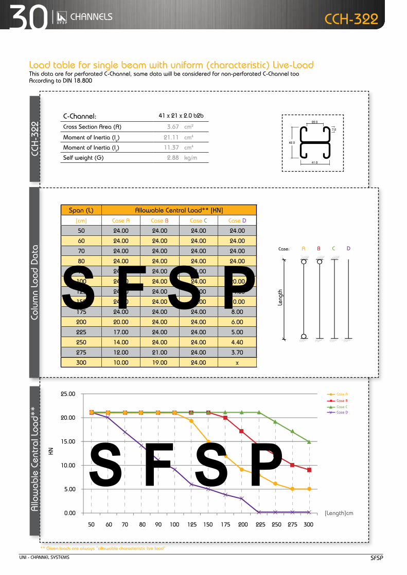
30 cHanneLS
allo
wab
le c
entr
al L
oad*
*cc
H-3
22ccH-322
Z
Z
YY
Z
Z
YY
Z
Z
YY
Z
Z
Y Y
21.0
7.0
41.0
21.0
41.0
22.0
42.0
7.0
41.0
22.0
41.0
7.0
41.0
41.0
41.0
22.0
82.0
7.0
41.0
22.0
50
30
13
allowable uniform Load
ACase:
Length
B C D
Leng
th
c-channel: 41 x 21 x 2.0 b2b
cross Section area (a) 3.67 cm2
moment of Inertia (Iy) 21.11 cm4
moment of Inertia (Iz) 11.37 cm4
Self weight (G) 2.88 kg/m
Span (L) allowable central Load** [kn][cm] case a case B case c case d
50 24.00 24.00 24.00 24.00
60 24.00 24.00 24.00 24.00
70 24.00 24.00 24.00 24.00
80 24.00 24.00 24.00 24.00
90 24.00 24.00 24.00 23.00
100 24.00 24.00 24.00 20.00
125 24.00 24.00 24.00 14.00
150 24.00 24.00 24.00 10.00
175 24.00 24.00 24.00 8.00
200 20.00 24.00 24.00 6.00
225 17.00 24.00 24.00 5.00
250 14.00 24.00 24.00 4.40
275 12.00 21.00 24.00 3.70
300 10.00 19.00 24.00 x
** Given loads are always “allowable characteristic live load”
15.00
20.00
25.00
0.00
5.00
10.00
50 60 70 80 90 100 125 150 175 200 225 250 275 300
kn
[Length]cm
case a
case B
case ccase d
colu
mn
Load
dat
a
Load table for single beam with uniform (characteristic) Live-Loadthis data are for perforated c-channel, same data will be considered for non-perforated c-channel tooaccording to dIn 18.800

unI - cHanneL SYStemSSfSP
31cHanneLS
ccH
-340
/341
thickness : 2.0 mm
Standard Length : 3.00 m
finishes : Pre-Galvanized,
Hot-dip Galvanized.
ccH-340/341
Z
Z
YY
Z
Z
YY
Z
Z
YY
Z
Z
Y Y
21.0
7.0
41.0
21.0
41.0
22.0
42.0
7.0
41.0
22.0
41.0
7.0
41.0
41.0
41.0
22.0
82.0
7.0
41.0
22.0
50
30
13
* Given loads are always “allowable characteristic live load”
Beam Load data
c-channel: 41x41x2.0
area of Shear (az) 1.34 cm2
moment of Inertia (Iy) 4.59 cm4
moment of Inertia (Iz) 6.99 cm4
min. Section modulus (Sy) 2.18 cm3
Warping constant (Iw) 138.49 cm6
torsional constant (It) 0.03 cm4
Plastic moment cap. (mpl,y) 0.64 knm
Self weight (G) 1.83 kg/m
chosen material: 40 B = S 235 JrG2
allowable Bending Stress 21,82 kn/cm2
allowable Shear Stress 12,60 kn/cm2
modulus of elasticity 21.000 kn/cm2
ccH-340
uniform Load* @
Span (L) allowable Load* deflection L / 360 L / 180[cm] q [kn/m] f [kn] u [mm] [L /x] q [kn/m] q [kn/m]
50 8.10 2.00 0.85 580 8.10 8.10
60 5.60 1.70 1.23 490 5.60 5.60
70 4.10 1.40 1.66 420 4.10 4.10
80 3.20 1.30 2.21 360 3.20 3.20
90 2.50 1.10 2.77 320 2.30 2.50
100 2.00 1.00 3.38 300 1.60 2.00
125 1.30 0.80 5.36 230 0.80 1.30
150 0.90 0.70 7.69 190 0.50 0.90
175 0.66 0.60 10.45 170 0.30 0.60
200 0.51 0.50 13.78 150 0.20 0.40
225 0.40 0.50 17.31 130 x 0.30
250 0.32 0.40 21.11 120 x 0.20
275 0.27 0.37 26.07 110 x x
300 0.23 0.35 31.46 100 x x
Chosen Material:Allowable Bending Stress 21,82 kN/cm²Allowable Shear Stress 12,60 kN/cm²Modulus of Elasticity 21.000 kN/cm²
40B = S 235 JRG2
C-Channel:Area of Shear (Az)
1,67 cm
Moment of Inertia (Iy)
5,87 cm
Moment of Inertia (Iz
y
z
)
8,76 cm
min. Section Modulus (Sy)
2,72 cm
Warping Constant (Iw)
171,52 cm
Torsional Constant (IT)
0,07 cm
Plastic Moment cap. (Mpl,y)
0,82 kNm
Self weight (G)
2,32 kg/m
C 41x41x2,52
4
4
3
6
4
cmcmcmcmcmcmkNmkg/m
2
4
4
3
6
4
C-Channel:Cross Section Area (A) cm2
Moment of Inertia (I ) cm4
4Moment of Inertia (I ) cmSelf Weight (G) kg/m
^
allowable Load
Span
f
Chosen Material:Allowable Bending Stress 21,82 kN/cm²Allowable Shear Stress 12,60 kN/cm²Modulus of Elasticity 21.000 kN/cm²
40B = S 235 JRG2
C-Channel:Area of Shear (Az)
1,67 cm
Moment of Inertia (Iy)
5,87 cm
Moment of Inertia (Iz
y
z
)
8,76 cm
min. Section Modulus (Sy)
2,72 cm
Warping Constant (Iw)
171,52 cm
Torsional Constant (IT)
0,07 cm
Plastic Moment cap. (Mpl,y)
0,82 kNm
Self weight (G)
2,32 kg/m
C 41x41x2,52
4
4
3
6
4
cmcmcmcmcmcmkNmkg/m
2
4
4
3
6
4
C-Channel:Cross Section Area (A) cm2
Moment of Inertia (I ) cm4
4Moment of Inertia (I ) cmSelf Weight (G) kg/m
^
allowable uniform Load
Span
q
Load table for single beam with uniform (characteristic) Live-Loadthis data are for perforated c-channel, same data will be considered for non-perforated c-channel tooaccording to dIn 18.800

unI - cHanneL SYStemS SfSP
32 cHanneLS ccH-340/341
6.007.008.009.00
0.001.002.003.004.005.00
50 60 70 80 90 100 125 150 175 200 225 250 275 300
25.00
30.00
35.00
0.00
5.00
10.00
15.00
20.00
50 60 70 80 90 100 125 150 175 200 225 250 275 300
2.50
3.00
3.50
0.00
0.50
1.00
1.50
2.00
80 90 100 125 150 175 200 225 250 275 300
[Span] cm
Beam LoadInG GraPH ccH-340/341
[Span] cm
allowable Loads
deflection @ allowable uniform Load
uniform Load @ allowable deflection
[Span] cm
mm
Chosen Material:Allowable Bending Stress 21,82 kN/cm²Allowable Shear Stress 12,60 kN/cm²Modulus of Elasticity 21.000 kN/cm²
40B = S 235 JRG2
C-Channel:Area of Shear (Az)
1,67 cm
Moment of Inertia (Iy)
5,87 cm
Moment of Inertia (Iz
y
z
)
8,76 cm
min. Section Modulus (Sy)
2,72 cm
Warping Constant (Iw)
171,52 cm
Torsional Constant (IT)
0,07 cm
Plastic Moment cap. (Mpl,y)
0,82 kNm
Self weight (G)
2,32 kg/m
C 41x41x2,52
4
4
3
6
4
cmcmcmcmcmcmkNmkg/m
2
4
4
3
6
4
C-Channel:Cross Section Area (A) cm2
Moment of Inertia (I ) cm4
4Moment of Inertia (I ) cmSelf Weight (G) kg/m
^
Chosen Material:Allowable Bending Stress 21,82 kN/cm²Allowable Shear Stress 12,60 kN/cm²Modulus of Elasticity 21.000 kN/cm²
40B = S 235 JRG2
C-Channel:Area of Shear (Az)
1,67 cm
Moment of Inertia (Iy)
5,87 cm
Moment of Inertia (Iz
y
z
)
8,76 cm
min. Section Modulus (Sy)
2,72 cm
Warping Constant (Iw)
171,52 cm
Torsional Constant (IT)
0,07 cm
Plastic Moment cap. (Mpl,y)
0,82 kNm
Self weight (G)
2,32 kg/m
C 41x41x2,52
4
4
3
6
4
cmcmcmcmcmcmkNmkg/m
2
4
4
3
6
4
C-Channel:Cross Section Area (A) cm2
Moment of Inertia (I ) cm4
4Moment of Inertia (I ) cmSelf Weight (G) kg/m
^
f
q [kn/m]
f [kn]
q
L /180
Chosen Material:Allowable Bending Stress 21,82 kN/cm²Allowable Shear Stress 12,60 kN/cm²Modulus of Elasticity 21.000 kN/cm²
40B = S 235 JRG2
C-Channel:Area of Shear (Az)
1,67 cm
Moment of Inertia (Iy)
5,87 cm
Moment of Inertia (Iz
y
z
)
8,76 cm
min. Section Modulus (Sy)
2,72 cm
Warping Constant (Iw)
171,52 cm
Torsional Constant (IT)
0,07 cm
Plastic Moment cap. (Mpl,y)
0,82 kNm
Self weight (G)
2,32 kg/m
C 41x41x2,52
4
4
3
6
4
cmcmcmcmcmcmkNmkg/m
2
4
4
3
6
4
C-Channel:Cross Section Area (A) cm2
Moment of Inertia (I ) cm4
4Moment of Inertia (I ) cmSelf Weight (G) kg/m
^
L /360
Chosen Material:Allowable Bending Stress 21,82 kN/cm²Allowable Shear Stress 12,60 kN/cm²Modulus of Elasticity 21.000 kN/cm²
40B = S 235 JRG2
C-Channel:Area of Shear (Az)
1,67 cm
Moment of Inertia (Iy)
5,87 cm
Moment of Inertia (Iz
y
z
)
8,76 cm
min. Section Modulus (Sy)
2,72 cm
Warping Constant (Iw)
171,52 cm
Torsional Constant (IT)
0,07 cm
Plastic Moment cap. (Mpl,y)
0,82 kNm
Self weight (G)
2,32 kg/m
C 41x41x2,52
4
4
3
6
4
cmcmcmcmcmcmkNmkg/m
2
4
4
3
6
4
C-Channel:Cross Section Area (A) cm2
Moment of Inertia (I ) cm4
4Moment of Inertia (I ) cmSelf Weight (G) kg/m
^
L /180
q [kn/m]
L /360
q [kn/m]
Chosen Material:Allowable Bending Stress 21,82 kN/cm²Allowable Shear Stress 12,60 kN/cm²Modulus of Elasticity 21.000 kN/cm²
40B = S 235 JRG2
C-Channel:Area of Shear (Az)
1,67 cm
Moment of Inertia (Iy)
5,87 cm
Moment of Inertia (Iz
y
z
)
8,76 cm
min. Section Modulus (Sy)
2,72 cm
Warping Constant (Iw)
171,52 cm
Torsional Constant (IT)
0,07 cm
Plastic Moment cap. (Mpl,y)
0,82 kNm
Self weight (G)
2,32 kg/m
C 41x41x2,52
4
4
3
6
4
cmcmcmcmcmcmkNmkg/m
2
4
4
3
6
4
C-Channel:Cross Section Area (A) cm2
Moment of Inertia (I ) cm4
4Moment of Inertia (I ) cmSelf Weight (G) kg/m
^
u
q [kn/m]
q
kn/m
kn/m
... k
n

unI - cHanneL SYStemSSfSP
33cHanneLS
ccH
-340
/341
allo
wab
le c
entr
al L
oad*
*
ccH-340/341
ccH-240/241
** Given loads are always “allowable characteristic live load”
allowable uniform Load
ACase:
Length
B C D
Leng
th
c-channel: 41 x 41 x 2.0
cross Section area (a) 2.33 cm2
moment of Inertia (Iy) 4.59 cm4
moment of Inertia (Iz) 6.99 cm4
Self weight (G) 1.83 kg/m
Span (L) allowable central Load** [kn][cm] case a case B case c case d
50 15.00 15.00 15.00 15.00
60 15.00 15.00 15.00 15.00
70 15.00 15.00 15.00 15.00
80 15.00 15.00 15.00 12.00
90 15.00 15.00 15.00 10.00
100 15.00 15.00 15.00 9.00
125 15.00 15.00 15.00 6.00
150 13.00 15.00 15.00 4.70
175 11.00 15.00 15.00 3.60
200 9.00 15.00 15.00 2.80
225 7.00 13.00 15.00 2.20
250 6.00 11.00 15.00 x
275 5.00 9.00 15.00 x
300 4.70 8.00 13.00 x
Z
Z
YY
Z
Z
YY
Z
Z
YY
Z
Z
Y Y
21.0
7.0
41.0
21.0
41.0
22.0
42.0
7.0
41.0
22.0
41.0
7.0
41.0
41.0
41.0
22.0
82.0
7.0
41.0
22.0
50
30
13
10.00
12.00
14.00
16.00
0.00
2.00
4.00
6.00
8.00
50 60 70 80 90 100 125 150 175 200 225 250 275 300
kn
[Length]cm
case a
case B
case ccase d
colu
mn
Load
dat
a
Load table for single beam with uniform (characteristic) Live-Loadthis data are for perforated c-channel, same data will be considered for non-perforated c-channel tooaccording to dIn 18.800

unI - cHanneL SYStemS SfSP
34 cHanneLS
thickness : 2.0 mmStandard Length : 3.00 m
finishes : Pre-Galvanized,
Hot-dip Galvanized.
ccH
-342
ccH-342
ccH-342
Z
Z
YY
Z
Z
YY
Z
Z
YY
Z
Z
Y Y
21.0
7.0
41.0
21.0
41.0
22.0
42.0
7.0
41.0
22.0
41.0
7.0
41.0
41.0
41.0
22.0
82.0
7.0
41.0
22.0
50
30
13
* Given loads are always “allowable characteristic live load”
Beam Load data
c-channel: 41x41x2.0 b2b
area of Shear (az) 1.88 cm2
moment of Inertia (Iy) 26.81 cm4
moment of Inertia (Iz) 14.04 cm4
min. Section modulus (Sy) 6.62 cm3
Warping constant (Iw) 113.65 cm6
torsional constant (It) 0.08 cm4
Plastic moment cap. (mpl,y) 1.98 knm
Self weight (G) 3.76 kg/m
chosen material: 40 B = S 235 JrG2
allowable Bending Stress 21,82 kn/cm2
allowable Shear Stress 12,60 kn/cm2
modulus of elasticity 21.000 kn/cm2
uniform Load* @
Span (L) allowable Load* deflection L / 360 L / 180[cm] q [kn/m] f [kn] u [mm] [L /x] q [kn/m] q [kn/m]
50 24.70 6.20 0.45 1.120 24.70 24.70
60 17.10 5.10 0.64 940 17.10 17.10
70 12.60 4.40 0.87 800 12.60 12.60
80 9.60 3.80 1.14 700 9.60 9.60
90 7.60 3.40 1.44 620 7.60 7.60
100 6.20 3.10 1.79 560 6.20 6.20
125 3.90 2.40 2.75 450 3.90 3.90
150 2.70 2.00 3.9 380 2.70 2.70
175 2.00 1.80 5.42 320 1.80 2.00
200 1.50 1.50 6.4 290 1.20 1.50
225 1.10 1.20 8.15 280 0.80 1.10
250 0.90 1.10 10.16 250 0.60 0.90
275 0.66 0.90 10.91 250 0.50 0.70
300 0.52 0.80 12.18 250 0.40 0.50
Chosen Material:Allowable Bending Stress 21,82 kN/cm²Allowable Shear Stress 12,60 kN/cm²Modulus of Elasticity 21.000 kN/cm²
40B = S 235 JRG2
C-Channel:Area of Shear (Az)
1,67 cm
Moment of Inertia (Iy)
5,87 cm
Moment of Inertia (Iz
y
z
)
8,76 cm
min. Section Modulus (Sy)
2,72 cm
Warping Constant (Iw)
171,52 cm
Torsional Constant (IT)
0,07 cm
Plastic Moment cap. (Mpl,y)
0,82 kNm
Self weight (G)
2,32 kg/m
C 41x41x2,52
4
4
3
6
4
cmcmcmcmcmcmkNmkg/m
2
4
4
3
6
4
C-Channel:Cross Section Area (A) cm2
Moment of Inertia (I ) cm4
4Moment of Inertia (I ) cmSelf Weight (G) kg/m
^
allowable Load
Span
F
Chosen Material:Allowable Bending Stress 21,82 kN/cm²Allowable Shear Stress 12,60 kN/cm²Modulus of Elasticity 21.000 kN/cm²
40B = S 235 JRG2
C-Channel:Area of Shear (Az)
1,67 cm
Moment of Inertia (Iy)
5,87 cm
Moment of Inertia (Iz
y
z
)
8,76 cm
min. Section Modulus (Sy)
2,72 cm
Warping Constant (Iw)
171,52 cm
Torsional Constant (IT)
0,07 cm
Plastic Moment cap. (Mpl,y)
0,82 kNm
Self weight (G)
2,32 kg/m
C 41x41x2,52
4
4
3
6
4
cmcmcmcmcmcmkNmkg/m
2
4
4
3
6
4
C-Channel:Cross Section Area (A) cm2
Moment of Inertia (I ) cm4
4Moment of Inertia (I ) cmSelf Weight (G) kg/m
^
allowable uniform Load
Span
q
Load table for single beam with uniform (characteristic) Live-Loadthis data are for perforated c-channel, same data will be considered for non-perforated c-channel tooaccording to dIn 18.800
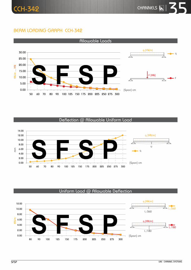
unI - cHanneL SYStemSSfSP
35cHanneLSccH-342
20.00
25.00
30.00
0.00
5.00
10.00
15.00
50 60 70 80 90 100 125 150 175 200 225 250 275 300
10.00
12.00
14.00
0.00
2.00
4.00
6.00
8.00
50 60 70 80 90 100 125 150 175 200 225 250 275 300
8.00
10.00
12.00
0.00
2.00
4.00
6.00
80 90 100 125 150 175 200 225 250 275 300
[Span] cm
[Span] cm
Beam LoadInG GraPH ccH-342
allowable Loads
deflection @ allowable uniform Load
uniform Load @ allowable deflection
[Span] cm
mm
Chosen Material:Allowable Bending Stress 21,82 kN/cm²Allowable Shear Stress 12,60 kN/cm²Modulus of Elasticity 21.000 kN/cm²
40B = S 235 JRG2
C-Channel:Area of Shear (Az)
1,67 cm
Moment of Inertia (Iy)
5,87 cm
Moment of Inertia (Iz
y
z
)
8,76 cm
min. Section Modulus (Sy)
2,72 cm
Warping Constant (Iw)
171,52 cm
Torsional Constant (IT)
0,07 cm
Plastic Moment cap. (Mpl,y)
0,82 kNm
Self weight (G)
2,32 kg/m
C 41x41x2,52
4
4
3
6
4
cmcmcmcmcmcmkNmkg/m
2
4
4
3
6
4
C-Channel:Cross Section Area (A) cm2
Moment of Inertia (I ) cm4
4Moment of Inertia (I ) cmSelf Weight (G) kg/m
^
Chosen Material:Allowable Bending Stress 21,82 kN/cm²Allowable Shear Stress 12,60 kN/cm²Modulus of Elasticity 21.000 kN/cm²
40B = S 235 JRG2
C-Channel:Area of Shear (Az)
1,67 cm
Moment of Inertia (Iy)
5,87 cm
Moment of Inertia (Iz
y
z
)
8,76 cm
min. Section Modulus (Sy)
2,72 cm
Warping Constant (Iw)
171,52 cm
Torsional Constant (IT)
0,07 cm
Plastic Moment cap. (Mpl,y)
0,82 kNm
Self weight (G)
2,32 kg/m
C 41x41x2,52
4
4
3
6
4
cmcmcmcmcmcmkNmkg/m
2
4
4
3
6
4
C-Channel:Cross Section Area (A) cm2
Moment of Inertia (I ) cm4
4Moment of Inertia (I ) cmSelf Weight (G) kg/m
^
f
q [kn/m]
f [kn]
q
L /180
Chosen Material:Allowable Bending Stress 21,82 kN/cm²Allowable Shear Stress 12,60 kN/cm²Modulus of Elasticity 21.000 kN/cm²
40B = S 235 JRG2
C-Channel:Area of Shear (Az)
1,67 cm
Moment of Inertia (Iy)
5,87 cm
Moment of Inertia (Iz
y
z
)
8,76 cm
min. Section Modulus (Sy)
2,72 cm
Warping Constant (Iw)
171,52 cm
Torsional Constant (IT)
0,07 cm
Plastic Moment cap. (Mpl,y)
0,82 kNm
Self weight (G)
2,32 kg/m
C 41x41x2,52
4
4
3
6
4
cmcmcmcmcmcmkNmkg/m
2
4
4
3
6
4
C-Channel:Cross Section Area (A) cm2
Moment of Inertia (I ) cm4
4Moment of Inertia (I ) cmSelf Weight (G) kg/m
^
L /360
Chosen Material:Allowable Bending Stress 21,82 kN/cm²Allowable Shear Stress 12,60 kN/cm²Modulus of Elasticity 21.000 kN/cm²
40B = S 235 JRG2
C-Channel:Area of Shear (Az)
1,67 cm
Moment of Inertia (Iy)
5,87 cm
Moment of Inertia (Iz
y
z
)
8,76 cm
min. Section Modulus (Sy)
2,72 cm
Warping Constant (Iw)
171,52 cm
Torsional Constant (IT)
0,07 cm
Plastic Moment cap. (Mpl,y)
0,82 kNm
Self weight (G)
2,32 kg/m
C 41x41x2,52
4
4
3
6
4
cmcmcmcmcmcmkNmkg/m
2
4
4
3
6
4
C-Channel:Cross Section Area (A) cm2
Moment of Inertia (I ) cm4
4Moment of Inertia (I ) cmSelf Weight (G) kg/m
^
L /180
q [kn/m]
L /360
q [kn/m]
Chosen Material:Allowable Bending Stress 21,82 kN/cm²Allowable Shear Stress 12,60 kN/cm²Modulus of Elasticity 21.000 kN/cm²
40B = S 235 JRG2
C-Channel:Area of Shear (Az)
1,67 cm
Moment of Inertia (Iy)
5,87 cm
Moment of Inertia (Iz
y
z
)
8,76 cm
min. Section Modulus (Sy)
2,72 cm
Warping Constant (Iw)
171,52 cm
Torsional Constant (IT)
0,07 cm
Plastic Moment cap. (Mpl,y)
0,82 kNm
Self weight (G)
2,32 kg/m
C 41x41x2,52
4
4
3
6
4
cmcmcmcmcmcmkNmkg/m
2
4
4
3
6
4
C-Channel:Cross Section Area (A) cm2
Moment of Inertia (I ) cm4
4Moment of Inertia (I ) cmSelf Weight (G) kg/m
^
u
q [kn/m]
q
kn/m
... k
nkn
/m
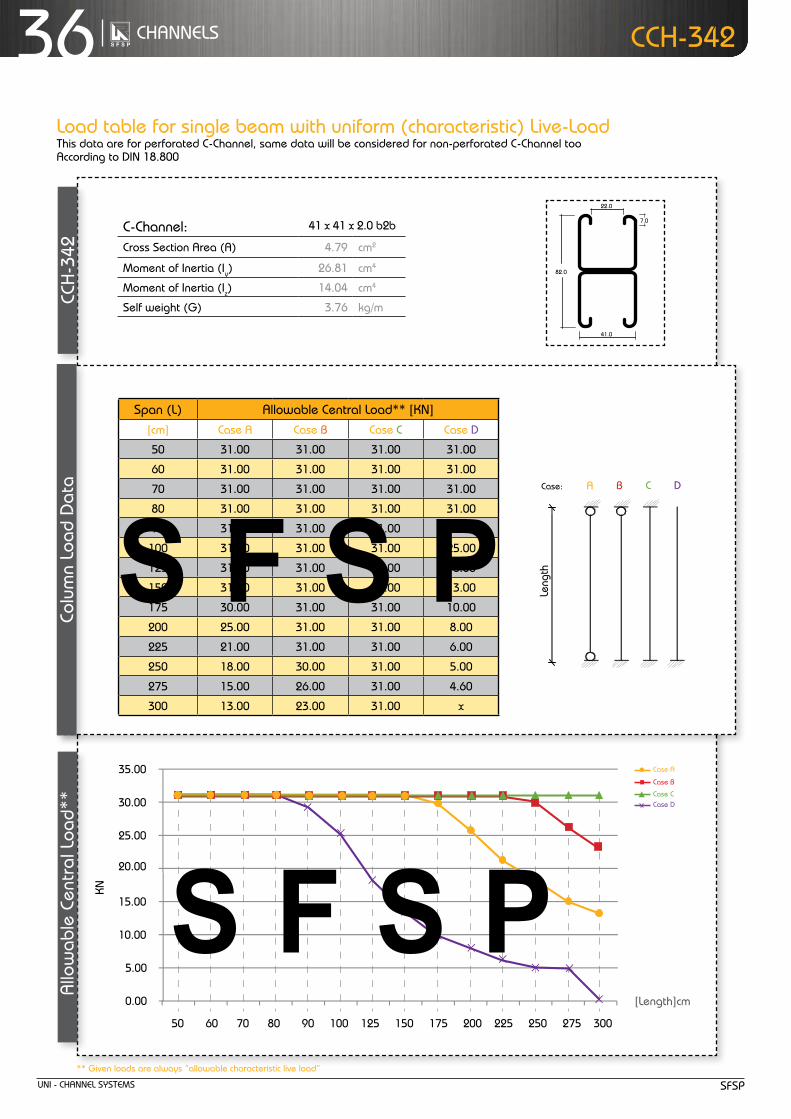
unI - cHanneL SYStemS SfSP
36 cHanneLS
allo
wab
le c
entr
al L
oad*
*cc
H-3
42ccH-342
Z
Z
YY
Z
Z
YY
Z
Z
YY
Z
Z
Y Y
21.0
7.0
41.0
21.0
41.0
22.0
42.0
7.0
41.0
22.0
41.0
7.0
41.0
41.0
41.0
22.0
82.0
7.0
41.0
22.0
50
30
13allowable uniform Load
ACase:
Length
B C D
Leng
th
c-channel: 41 x 41 x 2.0 b2b
cross Section area (a) 4.79 cm2
moment of Inertia (Iy) 26.81 cm4
moment of Inertia (Iz) 14.04 cm4
Self weight (G) 3.76 kg/m
Span (L) allowable central Load** [kn][cm] case a case B case c case d
50 31.00 31.00 31.00 31.00
60 31.00 31.00 31.00 31.00
70 31.00 31.00 31.00 31.00
80 31.00 31.00 31.00 31.00
90 31.00 31.00 31.00 29.00
100 31.00 31.00 31.00 25.00
125 31.00 31.00 31.00 18.00
150 31.00 31.00 31.00 13.00
175 30.00 31.00 31.00 10.00
200 25.00 31.00 31.00 8.00
225 21.00 31.00 31.00 6.00
250 18.00 30.00 31.00 5.00
275 15.00 26.00 31.00 4.60
300 13.00 23.00 31.00 x
** Given loads are always “allowable characteristic live load”
25.00
20.00
30.00
35.00
0.00
5.00
10.00
15.00
50 60 70 80 90 100 125 150 175 200 225 250 275 300
kn
[Length]cm
case a
case B
case ccase d
colu
mn
Load
dat
a
Load table for single beam with uniform (characteristic) Live-Loadthis data are for perforated c-channel, same data will be considered for non-perforated c-channel tooaccording to dIn 18.800

unI - cHanneL SYStemSSfSP
37cHanneLS
ccH
-420
/421
thickness : 2.5 mm
Standard Length : 3.00 m
finishes : Pre-Galvanized,
Hot-dip Galvanized.
ccH-420/421
Z
Z
YY
Z
Z
YY
Z
Z
YY
Z
Z
Y Y
21.0
7.0
41.0
21.0
41.0
22.0
42.0
7.0
41.0
22.0
41.0
7.0
41.0
41.0
41.0
22.0
82.0
7.0
41.0
22.0
50
30
13
* Given loads are always “allowable characteristic live load”
Beam Load data
c-channel: 41x21x2.5
area of Shear (az) 0.67 cm2
moment of Inertia (Iy) 1.03 cm4
moment of Inertia (Iz) 5.07 cm4
min. Section modulus (Sy) 0.89 cm3
Warping constant (Iw) 24.34 cm6
torsional constant (It) 0.06 cm4
Plastic moment cap. (mpl,y) 0.29 knm
Self weight (G) 1.56 kg/m
chosen material: 40 B = S 235 JrG2
allowable Bending Stress 21,82 kn/cm2
allowable Shear Stress 12,60 kn/cm2
modulus of elasticity 21.000 kn/cm2
ccH-420
uniform Load* @
Span (L) allowable Load* deflection L / 360 L / 180[cm] q [kn/m] f [kn] u [mm] [L /x] q [kn/m] q [kn/m]
50 3.30 0.80 1.55 320 3.00 3.30
60 2.30 0.70 2.24 270 1.70 2.30
70 1.70 0.60 3.07 230 1.10 1.70
80 1.30 0.50 4.01 200 0.70 1.30
90 1.00 0.50 4.94 180 0.50 1.00
100 0.80 0.40 6.02 170 0.40 0.70
125 0.53 0.33 9.74 130 0.19 0.38
150 0.37 0.28 14.09 110 x 0.22
175 0.27 0.24 19.05 90 x x
200 0.21 0.21 25.28 80 x x
225 0.16 0.28 30.86 70 x x
250 x x x x x x
275 x x x x x x
300 x x x x x x
Chosen Material:Allowable Bending Stress 21,82 kN/cm²Allowable Shear Stress 12,60 kN/cm²Modulus of Elasticity 21.000 kN/cm²
40B = S 235 JRG2
C-Channel:Area of Shear (Az)
1,67 cm
Moment of Inertia (Iy)
5,87 cm
Moment of Inertia (Iz
y
z
)
8,76 cm
min. Section Modulus (Sy)
2,72 cm
Warping Constant (Iw)
171,52 cm
Torsional Constant (IT)
0,07 cm
Plastic Moment cap. (Mpl,y)
0,82 kNm
Self weight (G)
2,32 kg/m
C 41x41x2,52
4
4
3
6
4
cmcmcmcmcmcmkNmkg/m
2
4
4
3
6
4
C-Channel:Cross Section Area (A) cm2
Moment of Inertia (I ) cm4
4Moment of Inertia (I ) cmSelf Weight (G) kg/m
^
allowable Load
Span
f
Chosen Material:Allowable Bending Stress 21,82 kN/cm²Allowable Shear Stress 12,60 kN/cm²Modulus of Elasticity 21.000 kN/cm²
40B = S 235 JRG2
C-Channel:Area of Shear (Az)
1,67 cm
Moment of Inertia (Iy)
5,87 cm
Moment of Inertia (Iz
y
z
)
8,76 cm
min. Section Modulus (Sy)
2,72 cm
Warping Constant (Iw)
171,52 cm
Torsional Constant (IT)
0,07 cm
Plastic Moment cap. (Mpl,y)
0,82 kNm
Self weight (G)
2,32 kg/m
C 41x41x2,52
4
4
3
6
4
cmcmcmcmcmcmkNmkg/m
2
4
4
3
6
4
C-Channel:Cross Section Area (A) cm2
Moment of Inertia (I ) cm4
4Moment of Inertia (I ) cmSelf Weight (G) kg/m
^
allowable uniform Load
Span
q
Load table for single beam with uniform (characteristic) Live-Loadthis data are for perforated c-channel, same data will be considered for non-perforated c-channel tooaccording to dIn 18.800

unI - cHanneL SYStemS SfSP
38 cHanneLS ccH-420/421
2.50
3.00
3.50
0.00
0.50
1.00
1.50
2.00
50 60 70 80 90 100 125 150 175 200 225 250 275 300
25.00
30.00
35.00
0.00
5.00
10.00
15.00
20.00
50 60 70 80 90 100 125 150 175 200 225 250 275 300
1.00
1.20
1.40
0.00
0.20
0.40
0.60
0.80
80 90 100 125 150 175 200 225 250 275 300
[Span] cm
Beam LoadInG GraPH ccH-420/421
[Span] cm
allowable Loads
deflection @ allowable uniform Load
uniform Load @ allowable deflection
[Span] cm
mm
Chosen Material:Allowable Bending Stress 21,82 kN/cm²Allowable Shear Stress 12,60 kN/cm²Modulus of Elasticity 21.000 kN/cm²
40B = S 235 JRG2
C-Channel:Area of Shear (Az)
1,67 cm
Moment of Inertia (Iy)
5,87 cm
Moment of Inertia (Iz
y
z
)
8,76 cm
min. Section Modulus (Sy)
2,72 cm
Warping Constant (Iw)
171,52 cm
Torsional Constant (IT)
0,07 cm
Plastic Moment cap. (Mpl,y)
0,82 kNm
Self weight (G)
2,32 kg/m
C 41x41x2,52
4
4
3
6
4
cmcmcmcmcmcmkNmkg/m
2
4
4
3
6
4
C-Channel:Cross Section Area (A) cm2
Moment of Inertia (I ) cm4
4Moment of Inertia (I ) cmSelf Weight (G) kg/m
^
Chosen Material:Allowable Bending Stress 21,82 kN/cm²Allowable Shear Stress 12,60 kN/cm²Modulus of Elasticity 21.000 kN/cm²
40B = S 235 JRG2
C-Channel:Area of Shear (Az)
1,67 cm
Moment of Inertia (Iy)
5,87 cm
Moment of Inertia (Iz
y
z
)
8,76 cm
min. Section Modulus (Sy)
2,72 cm
Warping Constant (Iw)
171,52 cm
Torsional Constant (IT)
0,07 cm
Plastic Moment cap. (Mpl,y)
0,82 kNm
Self weight (G)
2,32 kg/m
C 41x41x2,52
4
4
3
6
4
cmcmcmcmcmcmkNmkg/m
2
4
4
3
6
4
C-Channel:Cross Section Area (A) cm2
Moment of Inertia (I ) cm4
4Moment of Inertia (I ) cmSelf Weight (G) kg/m
^
f
q [kn/m]
f [kn]
q
L /180
Chosen Material:Allowable Bending Stress 21,82 kN/cm²Allowable Shear Stress 12,60 kN/cm²Modulus of Elasticity 21.000 kN/cm²
40B = S 235 JRG2
C-Channel:Area of Shear (Az)
1,67 cm
Moment of Inertia (Iy)
5,87 cm
Moment of Inertia (Iz
y
z
)
8,76 cm
min. Section Modulus (Sy)
2,72 cm
Warping Constant (Iw)
171,52 cm
Torsional Constant (IT)
0,07 cm
Plastic Moment cap. (Mpl,y)
0,82 kNm
Self weight (G)
2,32 kg/m
C 41x41x2,52
4
4
3
6
4
cmcmcmcmcmcmkNmkg/m
2
4
4
3
6
4
C-Channel:Cross Section Area (A) cm2
Moment of Inertia (I ) cm4
4Moment of Inertia (I ) cmSelf Weight (G) kg/m
^
L /360
Chosen Material:Allowable Bending Stress 21,82 kN/cm²Allowable Shear Stress 12,60 kN/cm²Modulus of Elasticity 21.000 kN/cm²
40B = S 235 JRG2
C-Channel:Area of Shear (Az)
1,67 cm
Moment of Inertia (Iy)
5,87 cm
Moment of Inertia (Iz
y
z
)
8,76 cm
min. Section Modulus (Sy)
2,72 cm
Warping Constant (Iw)
171,52 cm
Torsional Constant (IT)
0,07 cm
Plastic Moment cap. (Mpl,y)
0,82 kNm
Self weight (G)
2,32 kg/m
C 41x41x2,52
4
4
3
6
4
cmcmcmcmcmcmkNmkg/m
2
4
4
3
6
4
C-Channel:Cross Section Area (A) cm2
Moment of Inertia (I ) cm4
4Moment of Inertia (I ) cmSelf Weight (G) kg/m
^
L /180
q [kn/m]
L /360
q [kn/m]
Chosen Material:Allowable Bending Stress 21,82 kN/cm²Allowable Shear Stress 12,60 kN/cm²Modulus of Elasticity 21.000 kN/cm²
40B = S 235 JRG2
C-Channel:Area of Shear (Az)
1,67 cm
Moment of Inertia (Iy)
5,87 cm
Moment of Inertia (Iz
y
z
)
8,76 cm
min. Section Modulus (Sy)
2,72 cm
Warping Constant (Iw)
171,52 cm
Torsional Constant (IT)
0,07 cm
Plastic Moment cap. (Mpl,y)
0,82 kNm
Self weight (G)
2,32 kg/m
C 41x41x2,52
4
4
3
6
4
cmcmcmcmcmcmkNmkg/m
2
4
4
3
6
4
C-Channel:Cross Section Area (A) cm2
Moment of Inertia (I ) cm4
4Moment of Inertia (I ) cmSelf Weight (G) kg/m
^
u
q [kn/m]
q
kn/m
kn/m
... k
n

unI - cHanneL SYStemSSfSP
39cHanneLS
ccH
-420
/421
allo
wab
le c
entr
al L
oad*
*
ccH-420/421
ccH-240/241
** Given loads are always “allowable characteristic live load”
allowable uniform Load
ACase:
Length
B C D
Leng
th
c-channel: 41 x 41 x 2.5
cross Section area (a) 1.99 cm2
moment of Inertia (Iy) 1.03 cm4
moment of Inertia (Iz) 5.07 cm4
Self weight (G) 1.56 kg/m
Span (L) allowable central Load** [kn][cm] case a case B case c case d
50 13.00 13.00 13.00 8.00
60 13.00 13.00 13.00 6.00
70 13.00 13.00 13.00 4.70
80 11.00 13.00 13.00 3.70
90 9.00 13.00 13.00 3.00
100 8.00 13.00 13.00 2.50
125 5.00 10.00 13.00 x
150 4.20 7.00 12.00 x
175 3.20 5.00 10.00 x
200 2.50 4.70 8.00 x
225 2.00 3.80 6.00 x
250 x 3.20 5.00 x
275 x 2.70 4.90 x
300 x 2.30 4.20 x
Z
Z
YY
Z
Z
YY
Z
Z
YY
Z
Z
Y Y
21.0
7.0
41.0
21.0
41.0
22.0
42.0
7.0
41.0
22.0
41.0
7.0
41.0
41.0
41.0
22.0
82.0
7.0
41.0
22.0
50
30
13
10.00
8.00
12.00
14.00
0.00
2.00
4.00
6.00
50 60 70 80 90 100 125 150 175 200 225 250 275 300
kn
[Length]cm
case a
case B
case ccase d
colu
mn
Load
dat
a
Load table for single beam with uniform (characteristic) Live-Loadthis data are for perforated c-channel, same data will be considered for non-perforated c-channel tooaccording to dIn 18.800

unI - cHanneL SYStemS SfSP
40 cHanneLS
thickness : 2.5 mmStandard Length : 3.00 m
finishes : Pre-Galvanized,
Hot-dip Galvanized.
ccH
-422
ccH-422
Z
Z
YY
Z
Z
YY
Z
Z
YY
Z
Z
Y Y
21.0
7.0
41.0
21.0
41.0
22.0
42.0
7.0
41.0
22.0
41.0
7.0
41.0
41.0
41.0
22.0
82.0
7.0
41.0
22.0
50
30
13
ccH-422
* Given loads are always “allowable characteristic live load”
Beam Load data
c-channel: 41x21x2.5 b2b
area of Shear (az) 0.88 cm2
moment of Inertia (Iy) 5.55 cm4
moment of Inertia (Iz) 10.14 cm4
min. Section modulus (Sy) 2.65 cm3
Warping constant (Iw) 22.30 cm6
torsional constant (It) 0.12 cm4
Plastic moment cap. (mpl,y) 0.82 knm
Self weight (G) 3.13 kg/m
chosen material: 40 B = S 235 JrG2
allowable Bending Stress 21,82 kn/cm2
allowable Shear Stress 12,60 kn/cm2
modulus of elasticity 21.000 kn/cm2
uniform Load* @
Span (L) allowable Load* deflection L / 360 L / 180[cm] q [kn/m] f [kn] u [mm] [L /x] q [kn/m] q [kn/m]
50 9.90 2.50 0.86 580 9.90 9.90
60 6.90 2.10 1.25 480 6.90 6.90
70 5.00 1.80 1.68 420 5.00 5.00
80 3.90 1.60 2.23 360 3.90 3.90
90 3.00 1.40 2.75 330 2.70 3.00
100 2.50 1.30 3.49 290 2.00 2.50
125 1.60 1.00 5.46 230 1.00 1.60
150 1.10 0.80 7.78 190 0.60 1.10
175 0.80 0.70 10.48 170 0.40 0.70
200 0.62 0.60 13.85 140 0.20 0.50
225 0.49 0.60 17.54 130 0.20 0.30
250 0.39 0.50 21.27 120 x 0.30
275 0.33 0.50 26.36 100 x 0.20
300 0.27 0.40 30.54 100 x x
Chosen Material:Allowable Bending Stress 21,82 kN/cm²Allowable Shear Stress 12,60 kN/cm²Modulus of Elasticity 21.000 kN/cm²
40B = S 235 JRG2
C-Channel:Area of Shear (Az)
1,67 cm
Moment of Inertia (Iy)
5,87 cm
Moment of Inertia (Iz
y
z
)
8,76 cm
min. Section Modulus (Sy)
2,72 cm
Warping Constant (Iw)
171,52 cm
Torsional Constant (IT)
0,07 cm
Plastic Moment cap. (Mpl,y)
0,82 kNm
Self weight (G)
2,32 kg/m
C 41x41x2,52
4
4
3
6
4
cmcmcmcmcmcmkNmkg/m
2
4
4
3
6
4
C-Channel:Cross Section Area (A) cm2
Moment of Inertia (I ) cm4
4Moment of Inertia (I ) cmSelf Weight (G) kg/m
^
allowable Load
Span
f
Chosen Material:Allowable Bending Stress 21,82 kN/cm²Allowable Shear Stress 12,60 kN/cm²Modulus of Elasticity 21.000 kN/cm²
40B = S 235 JRG2
C-Channel:Area of Shear (Az)
1,67 cm
Moment of Inertia (Iy)
5,87 cm
Moment of Inertia (Iz
y
z
)
8,76 cm
min. Section Modulus (Sy)
2,72 cm
Warping Constant (Iw)
171,52 cm
Torsional Constant (IT)
0,07 cm
Plastic Moment cap. (Mpl,y)
0,82 kNm
Self weight (G)
2,32 kg/m
C 41x41x2,52
4
4
3
6
4
cmcmcmcmcmcmkNmkg/m
2
4
4
3
6
4
C-Channel:Cross Section Area (A) cm2
Moment of Inertia (I ) cm4
4Moment of Inertia (I ) cmSelf Weight (G) kg/m
^
allowable uniform Load
Span
q
Load table for single beam with uniform (characteristic) Live-Loadthis data are for perforated c-channel, same data will be considered for non-perforated c-channel tooaccording to dIn 18.800

unI - cHanneL SYStemSSfSP
41cHanneLSccH-422
8.00
10.00
12.00
0.00
2.00
4.00
6.00
50 60 70 80 90 100 125 150 175 200 225 250 275 300
25.00
30.00
35.00
0.00
5.00
10.00
15.00
20.00
50 60 70 80 90 100 125 150 175 200 225 250 275 300
3.00
3.50
4.00
4.50
0.00
0.50
1.00
1.50
2.00
2.50
80 90 100 125 150 175 200 225 250 275 300
[Span] cm
[Span] cm
Beam LoadInG GraPH ccH-422
allowable Loads
deflection @ allowable uniform Load
uniform Load @ allowable deflection
[Span] cm
mm
Chosen Material:Allowable Bending Stress 21,82 kN/cm²Allowable Shear Stress 12,60 kN/cm²Modulus of Elasticity 21.000 kN/cm²
40B = S 235 JRG2
C-Channel:Area of Shear (Az)
1,67 cm
Moment of Inertia (Iy)
5,87 cm
Moment of Inertia (Iz
y
z
)
8,76 cm
min. Section Modulus (Sy)
2,72 cm
Warping Constant (Iw)
171,52 cm
Torsional Constant (IT)
0,07 cm
Plastic Moment cap. (Mpl,y)
0,82 kNm
Self weight (G)
2,32 kg/m
C 41x41x2,52
4
4
3
6
4
cmcmcmcmcmcmkNmkg/m
2
4
4
3
6
4
C-Channel:Cross Section Area (A) cm2
Moment of Inertia (I ) cm4
4Moment of Inertia (I ) cmSelf Weight (G) kg/m
^
Chosen Material:Allowable Bending Stress 21,82 kN/cm²Allowable Shear Stress 12,60 kN/cm²Modulus of Elasticity 21.000 kN/cm²
40B = S 235 JRG2
C-Channel:Area of Shear (Az)
1,67 cm
Moment of Inertia (Iy)
5,87 cm
Moment of Inertia (Iz
y
z
)
8,76 cm
min. Section Modulus (Sy)
2,72 cm
Warping Constant (Iw)
171,52 cm
Torsional Constant (IT)
0,07 cm
Plastic Moment cap. (Mpl,y)
0,82 kNm
Self weight (G)
2,32 kg/m
C 41x41x2,52
4
4
3
6
4
cmcmcmcmcmcmkNmkg/m
2
4
4
3
6
4
C-Channel:Cross Section Area (A) cm2
Moment of Inertia (I ) cm4
4Moment of Inertia (I ) cmSelf Weight (G) kg/m
^
f
q [kn/m]
f [kn]
q
L /180
Chosen Material:Allowable Bending Stress 21,82 kN/cm²Allowable Shear Stress 12,60 kN/cm²Modulus of Elasticity 21.000 kN/cm²
40B = S 235 JRG2
C-Channel:Area of Shear (Az)
1,67 cm
Moment of Inertia (Iy)
5,87 cm
Moment of Inertia (Iz
y
z
)
8,76 cm
min. Section Modulus (Sy)
2,72 cm
Warping Constant (Iw)
171,52 cm
Torsional Constant (IT)
0,07 cm
Plastic Moment cap. (Mpl,y)
0,82 kNm
Self weight (G)
2,32 kg/m
C 41x41x2,52
4
4
3
6
4
cmcmcmcmcmcmkNmkg/m
2
4
4
3
6
4
C-Channel:Cross Section Area (A) cm2
Moment of Inertia (I ) cm4
4Moment of Inertia (I ) cmSelf Weight (G) kg/m
^
L /360
Chosen Material:Allowable Bending Stress 21,82 kN/cm²Allowable Shear Stress 12,60 kN/cm²Modulus of Elasticity 21.000 kN/cm²
40B = S 235 JRG2
C-Channel:Area of Shear (Az)
1,67 cm
Moment of Inertia (Iy)
5,87 cm
Moment of Inertia (Iz
y
z
)
8,76 cm
min. Section Modulus (Sy)
2,72 cm
Warping Constant (Iw)
171,52 cm
Torsional Constant (IT)
0,07 cm
Plastic Moment cap. (Mpl,y)
0,82 kNm
Self weight (G)
2,32 kg/m
C 41x41x2,52
4
4
3
6
4
cmcmcmcmcmcmkNmkg/m
2
4
4
3
6
4
C-Channel:Cross Section Area (A) cm2
Moment of Inertia (I ) cm4
4Moment of Inertia (I ) cmSelf Weight (G) kg/m
^
L /180
q [kn/m]
L /360
q [kn/m]
Chosen Material:Allowable Bending Stress 21,82 kN/cm²Allowable Shear Stress 12,60 kN/cm²Modulus of Elasticity 21.000 kN/cm²
40B = S 235 JRG2
C-Channel:Area of Shear (Az)
1,67 cm
Moment of Inertia (Iy)
5,87 cm
Moment of Inertia (Iz
y
z
)
8,76 cm
min. Section Modulus (Sy)
2,72 cm
Warping Constant (Iw)
171,52 cm
Torsional Constant (IT)
0,07 cm
Plastic Moment cap. (Mpl,y)
0,82 kNm
Self weight (G)
2,32 kg/m
C 41x41x2,52
4
4
3
6
4
cmcmcmcmcmcmkNmkg/m
2
4
4
3
6
4
C-Channel:Cross Section Area (A) cm2
Moment of Inertia (I ) cm4
4Moment of Inertia (I ) cmSelf Weight (G) kg/m
^
u
q [kn/m]
q
kn/m
... k
nkn
/m

unI - cHanneL SYStemS SfSP
42 cHanneLS
allo
wab
le c
entr
al L
oad*
*cc
H-4
22ccH-422
Z
Z
YY
Z
Z
YY
Z
Z
YY
Z
Z
Y Y
21.0
7.0
41.0
21.0
41.0
22.0
42.0
7.0
41.0
22.0
41.0
7.0
41.0
41.0
41.0
22.0
82.0
7.0
41.0
22.0
50
30
13
allowable uniform Load
ACase:
Length
B C D
Leng
th
c-channel: 41 x 21 x 2.5 b2b
cross Section area (a) 3.99 cm2
moment of Inertia (Iy) 5.55 cm4
moment of Inertia (Iz) 10.14 cm4
Self weight (G) 3.13 kg/m
Span (L) allowable central Load** [kn][cm] case a case B case c case d
50 26.00 26.00 26.00 26.00
60 26.00 26.00 26.00 25.00
70 26.00 26.00 26.00 20.00
80 26.00 26.00 26.00 17.00
90 26.00 26.00 26.00 14.00
100 26.00 26.00 26.00 11.00
125 24.00 26.00 26.00 8.00
150 18.00 26.00 26.00 5.00
175 14.00 24.00 26.00 4.40
200 11.00 20.00 26.00 3.50
225 9.00 17.00 26.00 x
250 8.00 14.00 24.00 x
275 6.00 12.00 21.00 x
300 5.00 11.00 18.00 x
** Given loads are always “allowable characteristic live load”
20.00
25.00
30.00
0.00
5.00
10.00
15.00
50 60 70 80 90 100 125 150 175 200 225 250 275 300
kn
[Length]cm
case a
case B
case ccase d
colu
mn
Load
dat
a
Load table for single beam with uniform (characteristic) Live-Loadthis data are for perforated c-channel, same data will be considered for non-perforated c-channel tooaccording to dIn 18.800

unI - cHanneL SYStemSSfSP
43cHanneLS
ccH
-440
/441
thickness : 2.5 mm
Standard Length : 3.00 m
finishes : Pre-Galvanized,
Hot-dip Galvanized.
ccH-440/441
* Given loads are always “allowable characteristic live load”
Beam Load data
c-channel: 41x41x2.5
area of Shear (az) 1.67 cm2
moment of Inertia (Iy) 5.87 cm4
moment of Inertia (Iz) 8.76 cm4
min. Section modulus (Sy) 2.72 cm3
Warping constant (Iw) 171.52 cm6
torsional constant (It) 0.07 cm4
Plastic moment cap. (mpl,y) 0.82 knm
Self weight (G) 2.32 kg/m
chosen material: 40 B = S 235 JrG2
allowable Bending Stress 21,82 kn/cm2
allowable Shear Stress 12,60 kn/cm2
modulus of elasticity 21.000 kn/cm2
uniform Load* @
Span (L) allowable Load* deflection L / 360 L / 180[cm] q [kn/m] f [kn] u [mm] [L /x] q [kn/m] q [kn/m]
50 10.10 2.50 0.83 600 10.10 10.10
60 7.00 2.10 1.20 500 7.00 7.00
70 5.20 1.80 1.65 420 5.20 5.20
80 4.00 1.60 2.16 370 4.00 4.00
90 3.10 1.40 2.69 340 2.90 3.10
100 2.50 1.30 3.30 300 2.10 2.50
125 1.60 1.00 5.16 240 1.10 1.60
150 1.10 0.80 7.35 200 0.60 1.10
175 0.80 0.70 9.91 180 0.40 0.80
200 0.63 0.60 13.31 150 0.30 0.50
225 0.50 0.60 16.92 130 0.20 0.40
250 0.41 0.50 21.15 120 x 0.30
275 0.33 0.50 24.92 110 x 0.20
300 0.28 0.40 29.95 100 x x
Z
Z
YY
Z
Z
YY
Z
Z
YY
Z
Z
Y Y
21.0
7.0
41.0
21.0
41.0
22.0
42.0
7.0
41.0
22.0
41.0
7.0
41.0
41.0
41.0
22.0
82.0
7.0
41.0
22.0
50
30
13
Chosen Material:Allowable Bending Stress 21,82 kN/cm²Allowable Shear Stress 12,60 kN/cm²Modulus of Elasticity 21.000 kN/cm²
40B = S 235 JRG2
C-Channel:Area of Shear (Az)
1,67 cm
Moment of Inertia (Iy)
5,87 cm
Moment of Inertia (Iz
y
z
)
8,76 cm
min. Section Modulus (Sy)
2,72 cm
Warping Constant (Iw)
171,52 cm
Torsional Constant (IT)
0,07 cm
Plastic Moment cap. (Mpl,y)
0,82 kNm
Self weight (G)
2,32 kg/m
C 41x41x2,52
4
4
3
6
4
cmcmcmcmcmcmkNmkg/m
2
4
4
3
6
4
C-Channel:Cross Section Area (A) cm2
Moment of Inertia (I ) cm4
4Moment of Inertia (I ) cmSelf Weight (G) kg/m
^
allowable Load
Span
f
Chosen Material:Allowable Bending Stress 21,82 kN/cm²Allowable Shear Stress 12,60 kN/cm²Modulus of Elasticity 21.000 kN/cm²
40B = S 235 JRG2
C-Channel:Area of Shear (Az)
1,67 cm
Moment of Inertia (Iy)
5,87 cm
Moment of Inertia (Iz
y
z
)
8,76 cm
min. Section Modulus (Sy)
2,72 cm
Warping Constant (Iw)
171,52 cm
Torsional Constant (IT)
0,07 cm
Plastic Moment cap. (Mpl,y)
0,82 kNm
Self weight (G)
2,32 kg/m
C 41x41x2,52
4
4
3
6
4
cmcmcmcmcmcmkNmkg/m
2
4
4
3
6
4
C-Channel:Cross Section Area (A) cm2
Moment of Inertia (I ) cm4
4Moment of Inertia (I ) cmSelf Weight (G) kg/m
^
allowable uniform Load
Span
q
ccH-440
Load table for single beam with uniform (characteristic) Live-Loadthis data are for perforated c-channel, same data will be considered for non-perforated c-channel tooaccording to dIn 18.800
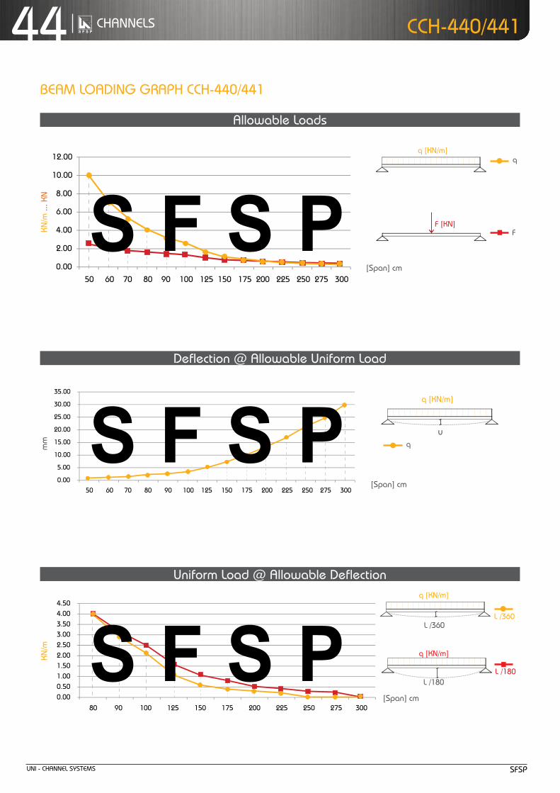
unI - cHanneL SYStemS SfSP
44 cHanneLS ccH-440/441
8.00
10.00
12.00
0.00
2.00
4.00
6.00
50 60 70 80 90 100 125 150 175 200 225 250 275 300
25.00
30.00
35.00
0.00
5.00
10.00
15.00
20.00
50 60 70 80 90 100 125 150 175 200 225 250 275 300
3.00
3.50
4.00
4.50
0.00
0.50
1.00
1.50
2.00
2.50
80 90 100 125 150 175 200 225 250 275 300
[Span] cm
Beam LoadInG GraPH ccH-440/441
[Span] cm
allowable Loads
deflection @ allowable uniform Load
uniform Load @ allowable deflection
[Span] cm
mm
Chosen Material:Allowable Bending Stress 21,82 kN/cm²Allowable Shear Stress 12,60 kN/cm²Modulus of Elasticity 21.000 kN/cm²
40B = S 235 JRG2
C-Channel:Area of Shear (Az)
1,67 cm
Moment of Inertia (Iy)
5,87 cm
Moment of Inertia (Iz
y
z
)
8,76 cm
min. Section Modulus (Sy)
2,72 cm
Warping Constant (Iw)
171,52 cm
Torsional Constant (IT)
0,07 cm
Plastic Moment cap. (Mpl,y)
0,82 kNm
Self weight (G)
2,32 kg/m
C 41x41x2,52
4
4
3
6
4
cmcmcmcmcmcmkNmkg/m
2
4
4
3
6
4
C-Channel:Cross Section Area (A) cm2
Moment of Inertia (I ) cm4
4Moment of Inertia (I ) cmSelf Weight (G) kg/m
^
Chosen Material:Allowable Bending Stress 21,82 kN/cm²Allowable Shear Stress 12,60 kN/cm²Modulus of Elasticity 21.000 kN/cm²
40B = S 235 JRG2
C-Channel:Area of Shear (Az)
1,67 cm
Moment of Inertia (Iy)
5,87 cm
Moment of Inertia (Iz
y
z
)
8,76 cm
min. Section Modulus (Sy)
2,72 cm
Warping Constant (Iw)
171,52 cm
Torsional Constant (IT)
0,07 cm
Plastic Moment cap. (Mpl,y)
0,82 kNm
Self weight (G)
2,32 kg/m
C 41x41x2,52
4
4
3
6
4
cmcmcmcmcmcmkNmkg/m
2
4
4
3
6
4
C-Channel:Cross Section Area (A) cm2
Moment of Inertia (I ) cm4
4Moment of Inertia (I ) cmSelf Weight (G) kg/m
^
f
q [kn/m]
f [kn]
q
L /180
Chosen Material:Allowable Bending Stress 21,82 kN/cm²Allowable Shear Stress 12,60 kN/cm²Modulus of Elasticity 21.000 kN/cm²
40B = S 235 JRG2
C-Channel:Area of Shear (Az)
1,67 cm
Moment of Inertia (Iy)
5,87 cm
Moment of Inertia (Iz
y
z
)
8,76 cm
min. Section Modulus (Sy)
2,72 cm
Warping Constant (Iw)
171,52 cm
Torsional Constant (IT)
0,07 cm
Plastic Moment cap. (Mpl,y)
0,82 kNm
Self weight (G)
2,32 kg/m
C 41x41x2,52
4
4
3
6
4
cmcmcmcmcmcmkNmkg/m
2
4
4
3
6
4
C-Channel:Cross Section Area (A) cm2
Moment of Inertia (I ) cm4
4Moment of Inertia (I ) cmSelf Weight (G) kg/m
^
L /360
Chosen Material:Allowable Bending Stress 21,82 kN/cm²Allowable Shear Stress 12,60 kN/cm²Modulus of Elasticity 21.000 kN/cm²
40B = S 235 JRG2
C-Channel:Area of Shear (Az)
1,67 cm
Moment of Inertia (Iy)
5,87 cm
Moment of Inertia (Iz
y
z
)
8,76 cm
min. Section Modulus (Sy)
2,72 cm
Warping Constant (Iw)
171,52 cm
Torsional Constant (IT)
0,07 cm
Plastic Moment cap. (Mpl,y)
0,82 kNm
Self weight (G)
2,32 kg/m
C 41x41x2,52
4
4
3
6
4
cmcmcmcmcmcmkNmkg/m
2
4
4
3
6
4
C-Channel:Cross Section Area (A) cm2
Moment of Inertia (I ) cm4
4Moment of Inertia (I ) cmSelf Weight (G) kg/m
^
L /180
q [kn/m]
L /360
q [kn/m]
Chosen Material:Allowable Bending Stress 21,82 kN/cm²Allowable Shear Stress 12,60 kN/cm²Modulus of Elasticity 21.000 kN/cm²
40B = S 235 JRG2
C-Channel:Area of Shear (Az)
1,67 cm
Moment of Inertia (Iy)
5,87 cm
Moment of Inertia (Iz
y
z
)
8,76 cm
min. Section Modulus (Sy)
2,72 cm
Warping Constant (Iw)
171,52 cm
Torsional Constant (IT)
0,07 cm
Plastic Moment cap. (Mpl,y)
0,82 kNm
Self weight (G)
2,32 kg/m
C 41x41x2,52
4
4
3
6
4
cmcmcmcmcmcmkNmkg/m
2
4
4
3
6
4
C-Channel:Cross Section Area (A) cm2
Moment of Inertia (I ) cm4
4Moment of Inertia (I ) cmSelf Weight (G) kg/m
^
u
q [kn/m]
q
kn/m
kn/m
... k
n

Uni - Channel SyStemSSFSP
45ChannelS
CCh
-440
/441
allo
wab
le C
entr
al l
oad*
*
CCh-440/441
CCh-240/241
** Given loads are always “allowable characteristic live load”
allowable uniform Load
ACase:
Length
B C D
Leng
th
C-Channel: 41 x 41 x 2.5
Cross Section area (a) 2.95 cm2
moment of inertia (iy) 5.87 cm4
moment of inertia (iz) 8.76 cm4
Self weight (G) 2.32 kg/m
Span (l) allowable Central load** [Kn][cm] Case a Case B Case C Case D
50 19.00 19.00 19.00 19.00
60 19.00 19.00 19.00 19.00
70 19.00 19.00 19.00 19.00
80 19.00 19.00 19.00 16.00
90 19.00 19.00 19.00 13.00
100 19.00 19.00 19.00 11.00
125 19.00 19.00 19.00 8.00
150 17.00 19.00 19.00 5.00
175 14.00 19.00 19.00 4.50
200 11.00 19.00 19.00 3.60
225 9.00 16.00 19.00 2.90
250 8.00 14.00 19.00 x
275 6.00 12.00 19.00 x
300 5.00 10.00 17.00 x
Z
Z
YY
Z
Z
YY
Z
Z
YY
Z
Z
Y Y
21.0
7.0
41.0
21.0
41.0
22.0
42.0
7.0
41.0
22.0
41.0
7.0
41.0
41.0
41.0
22.0
82.0
7.0
41.0
22.0
50
30
13
16.00
18.00
20.00
12.00
10.00
14.00
6.00
8.00
2.00
0.00
4.00
50 60 70 80 90 100 125 150 175 200 225 250 275 300
Kn
[length]cm
Case a
Case B
Case CCase D
Colu
mn
load
Dat
a
load table for single beam with uniform (characteristic) live-loadthis data are for perforated C-Channel, same data will be considered for non-perforated C-Channel tooaccording to Din 18.800

Uni - Channel SyStemS SFSP
46 ChannelS
thickness : 2.5 mmStandard length : 3.00 m
Finishes : Pre-Galvanized,
hot-Dip Galvanized.
CCh
-442
CCh-442
Z
Z
YY
Z
Z
YY
Z
Z
YY
Z
Z
Y Y
21.0
7.0
41.0
21.0
41.0
22.0
42.0
7.0
41.0
22.0
41.0
7.0
41.0
41.0
41.0
22.0
82.0
7.0
41.0
22.0
50
30
13
CCh-442
* Given loads are always “allowable characteristic live load”
Beam load Data
C-Channel: 41x41x2.5 b2b
area of Shear (az) 2.37 cm2
moment of inertia (iy) 34.08 cm4
moment of inertia (iz) 17.56 cm4
min. Section modulus (Sy) 8.31 cm3
Warping Constant (iw) 140.95 cm6
torsional Constant (it) 0.16 cm4
Plastic moment cap. (mpl,y) 2.51 knm
Self weight (G) 4.70 kg/m
Chosen material: 40 B = S 235 JRG2
allowable Bending Stress 21,82 kn/cm2
allowable Shear Stress 12,60 kn/cm2
modulus of elasticity 21.000 kn/cm2
Uniform load* @
Span (l) allowable load* Deflection l / 360 l / 180[cm] q [kn/m] F [kn] U [mm] [l /X] q [kn/m] q [kn/m]
50 30.90 7.70 0.44 1.140 30.90 30.90
60 21.50 6.50 0.63 950 21.50 21.50
70 15.80 5.50 0.86 810 15.80 15.80
80 12.10 4.80 1.13 710 12.10 12.10
90 9.60 4.30 1.43 630 9.60 9.60
100 7.70 3.90 1.75 570 7.70 7.70
125 5.00 3.10 2.78 450 5.00 5.00
150 3.40 2.60 3.91 380 3.40 3.40
175 2.50 2.20 5.33 330 2.30 2.50
200 1.90 1.90 6.91 290 1.50 1.90
225 1.50 1.70 8.74 260 1.10 1.50
250 1.20 1.50 10.66 230 0.80 1.20
275 1.00 1.40 13.01 210 0.60 1.00
300 0.77 1.20 14.18 210 0.50 0.80
Chosen Material:Allowable Bending Stress 21,82 kN/cm²Allowable Shear Stress 12,60 kN/cm²Modulus of Elasticity 21.000 kN/cm²
40B = S 235 JRG2
C-Channel:Area of Shear (Az)
1,67 cm
Moment of Inertia (Iy)
5,87 cm
Moment of Inertia (Iz
y
z
)
8,76 cm
min. Section Modulus (Sy)
2,72 cm
Warping Constant (Iw)
171,52 cm
Torsional Constant (IT)
0,07 cm
Plastic Moment cap. (Mpl,y)
0,82 kNm
Self weight (G)
2,32 kg/m
C 41x41x2,52
4
4
3
6
4
cmcmcmcmcmcmkNmkg/m
2
4
4
3
6
4
C-Channel:Cross Section Area (A) cm2
Moment of Inertia (I ) cm4
4Moment of Inertia (I ) cmSelf Weight (G) kg/m
^
allowable load
Span
F
Chosen Material:Allowable Bending Stress 21,82 kN/cm²Allowable Shear Stress 12,60 kN/cm²Modulus of Elasticity 21.000 kN/cm²
40B = S 235 JRG2
C-Channel:Area of Shear (Az)
1,67 cm
Moment of Inertia (Iy)
5,87 cm
Moment of Inertia (Iz
y
z
)
8,76 cm
min. Section Modulus (Sy)
2,72 cm
Warping Constant (Iw)
171,52 cm
Torsional Constant (IT)
0,07 cm
Plastic Moment cap. (Mpl,y)
0,82 kNm
Self weight (G)
2,32 kg/m
C 41x41x2,52
4
4
3
6
4
cmcmcmcmcmcmkNmkg/m
2
4
4
3
6
4
C-Channel:Cross Section Area (A) cm2
Moment of Inertia (I ) cm4
4Moment of Inertia (I ) cmSelf Weight (G) kg/m
^
allowable Uniform load
Span
q
load table for single beam with uniform (characteristic) live-loadthis data are for perforated C-Channel, same data will be considered for non-perforated C-Channel tooaccording to Din 18.800

Uni - Channel SyStemSSFSP
47ChannelSCCh-442
25.00
30.00
35.00
0.00
5.00
10.00
15.00
20.00
50 60 70 80 90 100 125 150 175 200 225 250 275 300
10.00
12.00
14.00
16.00
0.00
2.00
4.00
6.00
8.00
50 60 70 80 90 100 125 150 175 200 225 250 275 300
10.00
12.00
14.00
0.00
2.00
4.00
6.00
8.00
80 90 100 125 150 175 200 225 250 275 300
[Span] cm
[Span] cm
Beam lOaDinG GRaPh CCh-442
allowable loads
Deflection @ allowable Uniform load
Uniform load @ allowable Deflection
[Span] cm
mm
Chosen Material:Allowable Bending Stress 21,82 kN/cm²Allowable Shear Stress 12,60 kN/cm²Modulus of Elasticity 21.000 kN/cm²
40B = S 235 JRG2
C-Channel:Area of Shear (Az)
1,67 cm
Moment of Inertia (Iy)
5,87 cm
Moment of Inertia (Iz
y
z
)
8,76 cm
min. Section Modulus (Sy)
2,72 cm
Warping Constant (Iw)
171,52 cm
Torsional Constant (IT)
0,07 cm
Plastic Moment cap. (Mpl,y)
0,82 kNm
Self weight (G)
2,32 kg/m
C 41x41x2,52
4
4
3
6
4
cmcmcmcmcmcmkNmkg/m
2
4
4
3
6
4
C-Channel:Cross Section Area (A) cm2
Moment of Inertia (I ) cm4
4Moment of Inertia (I ) cmSelf Weight (G) kg/m
^
Chosen Material:Allowable Bending Stress 21,82 kN/cm²Allowable Shear Stress 12,60 kN/cm²Modulus of Elasticity 21.000 kN/cm²
40B = S 235 JRG2
C-Channel:Area of Shear (Az)
1,67 cm
Moment of Inertia (Iy)
5,87 cm
Moment of Inertia (Iz
y
z
)
8,76 cm
min. Section Modulus (Sy)
2,72 cm
Warping Constant (Iw)
171,52 cm
Torsional Constant (IT)
0,07 cm
Plastic Moment cap. (Mpl,y)
0,82 kNm
Self weight (G)
2,32 kg/m
C 41x41x2,52
4
4
3
6
4
cmcmcmcmcmcmkNmkg/m
2
4
4
3
6
4
C-Channel:Cross Section Area (A) cm2
Moment of Inertia (I ) cm4
4Moment of Inertia (I ) cmSelf Weight (G) kg/m
^
F
q [Kn/m]
F [Kn]
q
l /180
Chosen Material:Allowable Bending Stress 21,82 kN/cm²Allowable Shear Stress 12,60 kN/cm²Modulus of Elasticity 21.000 kN/cm²
40B = S 235 JRG2
C-Channel:Area of Shear (Az)
1,67 cm
Moment of Inertia (Iy)
5,87 cm
Moment of Inertia (Iz
y
z
)
8,76 cm
min. Section Modulus (Sy)
2,72 cm
Warping Constant (Iw)
171,52 cm
Torsional Constant (IT)
0,07 cm
Plastic Moment cap. (Mpl,y)
0,82 kNm
Self weight (G)
2,32 kg/m
C 41x41x2,52
4
4
3
6
4
cmcmcmcmcmcmkNmkg/m
2
4
4
3
6
4
C-Channel:Cross Section Area (A) cm2
Moment of Inertia (I ) cm4
4Moment of Inertia (I ) cmSelf Weight (G) kg/m
^
l /360
Chosen Material:Allowable Bending Stress 21,82 kN/cm²Allowable Shear Stress 12,60 kN/cm²Modulus of Elasticity 21.000 kN/cm²
40B = S 235 JRG2
C-Channel:Area of Shear (Az)
1,67 cm
Moment of Inertia (Iy)
5,87 cm
Moment of Inertia (Iz
y
z
)
8,76 cm
min. Section Modulus (Sy)
2,72 cm
Warping Constant (Iw)
171,52 cm
Torsional Constant (IT)
0,07 cm
Plastic Moment cap. (Mpl,y)
0,82 kNm
Self weight (G)
2,32 kg/m
C 41x41x2,52
4
4
3
6
4
cmcmcmcmcmcmkNmkg/m
2
4
4
3
6
4
C-Channel:Cross Section Area (A) cm2
Moment of Inertia (I ) cm4
4Moment of Inertia (I ) cmSelf Weight (G) kg/m
^
l /180
q [Kn/m]
l /360
q [Kn/m]
Chosen Material:Allowable Bending Stress 21,82 kN/cm²Allowable Shear Stress 12,60 kN/cm²Modulus of Elasticity 21.000 kN/cm²
40B = S 235 JRG2
C-Channel:Area of Shear (Az)
1,67 cm
Moment of Inertia (Iy)
5,87 cm
Moment of Inertia (Iz
y
z
)
8,76 cm
min. Section Modulus (Sy)
2,72 cm
Warping Constant (Iw)
171,52 cm
Torsional Constant (IT)
0,07 cm
Plastic Moment cap. (Mpl,y)
0,82 kNm
Self weight (G)
2,32 kg/m
C 41x41x2,52
4
4
3
6
4
cmcmcmcmcmcmkNmkg/m
2
4
4
3
6
4
C-Channel:Cross Section Area (A) cm2
Moment of Inertia (I ) cm4
4Moment of Inertia (I ) cmSelf Weight (G) kg/m
^
u
q [Kn/m]
q
Kn/m
... K
nKn
/m
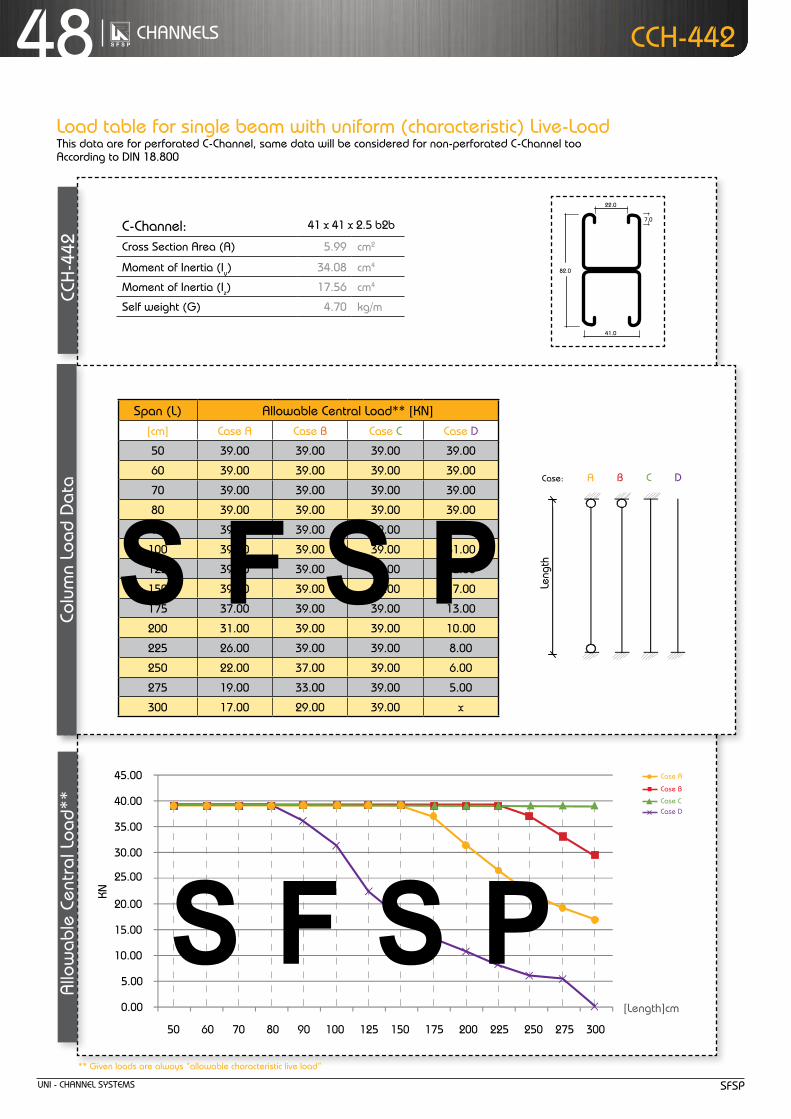
Uni - Channel SyStemS SFSP
48 ChannelS
allo
wab
le C
entr
al l
oad*
* C
Ch-4
42CCh-442
Z
Z
YY
Z
Z
YY
Z
Z
YY
Z
Z
Y Y
21.0
7.0
41.0
21.0
41.0
22.0
42.0
7.0
41.0
22.0
41.0
7.0
41.0
41.0
41.0
22.0
82.0
7.0
41.0
22.0
50
30
13
allowable uniform Load
ACase:
Length
B C D
Leng
th
C-Channel: 41 x 41 x 2.5 b2b
Cross Section area (a) 5.99 cm2
moment of inertia (iy) 34.08 cm4
moment of inertia (iz) 17.56 cm4
Self weight (G) 4.70 kg/m
Span (l) allowable Central load** [Kn][cm] Case a Case B Case C Case D
50 39.00 39.00 39.00 39.00
60 39.00 39.00 39.00 39.00
70 39.00 39.00 39.00 39.00
80 39.00 39.00 39.00 39.00
90 39.00 39.00 39.00 36.00
100 39.00 39.00 39.00 31.00
125 39.00 39.00 39.00 22.00
150 39.00 39.00 39.00 17.00
175 37.00 39.00 39.00 13.00
200 31.00 39.00 39.00 10.00
225 26.00 39.00 39.00 8.00
250 22.00 37.00 39.00 6.00
275 19.00 33.00 39.00 5.00
300 17.00 29.00 39.00 x
** Given loads are always “allowable characteristic live load”
30.00
25.00
35.00
40.00
45.00
0.00
5.00
10.00
15.00
20.00
50 60 70 80 90 100 125 150 175 200 225 250 275 300
Kn
[length]cm
Case a
Case B
Case CCase D
Colu
mn
load
Dat
a
load table for single beam with uniform (characteristic) live-loadthis data are for perforated C-Channel, same data will be considered for non-perforated C-Channel tooaccording to Din 18.800

Uni - Channel SyStemSSFSP
49ChannelS
tOOtheD ChannelS
toothed channels provide shock-resistant fixing for non-slip connections and higher safety requirements.to make fitting easier, the locking plates and t-head bolts should be pre-mounted on the fittings to be attached.

Uni - Channel SyStemS SFSP
50 ChannelS tOOtheD Channel
CCh-220t /221t (41x21x1 .5)
Z
Z
YY21.0
41.0
Z
Z
YY41.0
41.0
Due to its positive locking feature, this channel is ideally suited when increased loading capacities in longitudinal direction are required.
ChannelCCh
Channel Weight
Cross Section
moment of inertia
Section modulus
Bending capacity at span l
G a iy iz Wy Wz 0.50 m 1.00 m 1.50 m
[Kg/m] [cm2] [cm4] [cm4] [cm3] [cm3] F [Kn]
220t 1.09 1.39 0.81 3.36 0.64 1.91 1.12 0.56 0.19
221t 0.97 1.23 0.70 3.34 0.60 1.70 1.04 0.52 0.17
222t 1.94 2.47 3.55 6.69 1.69 3.82 2.94 1.47 0.49
max. tensile / transverse load
FZ FQ
F
l [m]
Bending capacity at span l
Z
Z
y
yX
thickness : 1.5 mmStandard length : 3.00 m Finishes : Pre-Galvanized, hot-Dip Galvanized.
ChannelCCh
Channel Weight
Cross Section
moment of inertia
Section modulus
Bending capacity at span l
G a iy iz Wy Wz 0.50 m 1.00 m 1.50 m
[Kg/m] [cm2] [cm4] [cm4] [cm3] [cm3] F [Kn]
240t 1.56 1.99 4.36 5.70 1.86 2.99 3.24 1.62 1.08
241t 1.44 1.83 3.87 5.68 1.76 2.66 3.06 1.53 1.02
242t 2.88 3.67 21.11 11.37 5.15 5.98 8.98 4.49 2.90
Z
Z
YY21.0
41.0
Z
Z
YY41.0
41.0
Due to its positive locking feature, this channel is ideally suited when increased loading capacities in longitudinal direction are required.
max. tensile / transverse load
FZ FQ
F
l [m]
Bending capacity at span l
Z
Z
y
yX
CCh-240t /241t (41x41x1 .5) thickness : 1.5 mmStandard length : 3.00 m Finishes : Pre-Galvanized, hot-Dip Galvanized.
CCh - 241t
CCh - 240t
CCh - 242t
CCh - 221t
CCh - 220t
CCh - 222t

Uni - Channel SyStemSSFSP
51ChannelS
ChannelCCh
Channel Weight
Cross Section
moment of inertia
Section modulus
Bending capacity at span l
G a iy iz Wy Wz 0.50 m 1.00 m 1.50 m
[Kg/m] [cm2] [cm4] [cm4] [cm3] [cm3] F [Kn]
340t 2.04 2.60 5.41 7.03 2.35 3.86 4.10 2.05 1.37
341t 1.83 2.33 4.59 6.99 2.18 3.43 3.80 1.90 1.26
342t 3.76 4.79 26.81 14.04 6.62 7.72 11.54 5.77 3.85
ChannelCCh
Channel Weight
Cross Section
moment of inertia
Section modulus
Bending capacity at span l
G a iy iz Wy Wz 0.50 m 1.00 m 1.50 m
[Kg/m] [cm2] [cm4] [cm4] [cm3] [cm3] F [Kn]
320t 1.44 1.83 0.99 4.77 0.84 2.37 1.46 0.73 0.24
321t 1.27 1.62 0.88 4.25 0.75 2.11 1.30 0.65 0.22
322t 2.54 3.24 4.60 8.51 2.19 4.74 3.80 1.91 1.27
tOOtheD Channel
Z
Z
YY21.0
41.0
Z
Z
YY41.0
41.0
max. tensile / transverse load
FZ FQ
F
l [m]
Bending capacity at span l
Z
Z
YY21.0
41.0
Z
Z
YY41.0
41.0
max. tensile / transverse load
FZ FQ
F
l [m]
Bending capacity at span l
Z
Z
y
yX
Z
Z
y
yX
Due to its positive locking feature, this channel is ideally suited when increased loading capacities in longitudinal direction are required.
Due to its positive locking feature, this channel is ideally suited when increased loading capacities in longitudinal direction are required.
CCh - 321t
CCh - 341t
CCh - 320t
CCh - 340t
CCh - 322t
CCh - 342t
CCh-320t /321t (41x21x2 .0)
CCh-340t /341t (41x41x2 .0)
thickness : 2.0 mmStandard length : 3.00 m Finishes : Pre-Galvanized, hot-Dip Galvanized.
thickness : 2.0 mmStandard length : 3.00 m Finishes : Pre-Galvanized, hot-Dip Galvanized.

Uni - Channel SyStemS SFSP
52 ChannelS
CCh-420t/421t (41x21x2.5)
Z
Z
YY21.0
41.0
Z
Z
YY41.0
41.0
ChannelCCh
Channel Weight
Cross Section
moment of inertia
Section modulus
Bending capacity at span l
G a iy iz Wy Wz 0.50 m 1.00 m 1.50 m
[Kg/m] [cm2] [cm4] [cm4] [cm3] [cm3] F [Kn]
420t 1.75 2.18 1.15 4.92 0.89 2.50 1.55 0.78 0.32
421t 1.54 1.95 1.01 4.99 0.86 2.49 1.5 0.75 0.3
422t 3.50 4.48 5.55 10.15 2.63 5.31 4.58 2.29 1.53
max. tensile / transverse load
FZ FQ
F
l [m]
Bending capacity at span l
Z
Z
y
yX
Due to its positive locking feature, this channel is ideally suited when increased loading capacities in longitudinal direction are required.
CCh - 221t
CCh - 220t
CCh - 222t
thickness : 2.5 mmStandard length : 3.00 m Finishes : Pre-Galvanized, hot-Dip Galvanized.
tOOtheD Channel
CCh-440t/441t (41x41x2.5)
Z
Z
YY21.0
41.0
Z
Z
YY41.0
41.0
ChannelCCh
Channel Weight
Cross Section
moment of inertia
Section modulus
Bending capacity at span l
G a iy iz Wy Wz 0.50 m 1.00 m 1.50 m
[Kg/m] [cm2] [cm4] [cm4] [cm3] [cm3] F [Kn]
440t 2.57 3.28 6.52 8.78 2.76 4.39 4.81 2.41 1.60
441t 2.30 2.91 5.62 8.74 2.57 4.35 4.48 2.24 1.49
442t 4.90 6.34 32.02 17.54 8.11 8.85 14.14 7.07 4.71
max. tensile / transverse load
FZ FQ
F
l [m]
Bending capacity at span l
Z
Z
y
yX
CCh - 441t
CCh - 440t
CCh - 442t
Due to its positive locking feature, this channel is ideally suited when increased loading capacities in longitudinal direction are required.
thickness : 2.5 mmStandard length : 3.00 m Finishes : Pre-Galvanized, hot-Dip Galvanized.

FittinGS
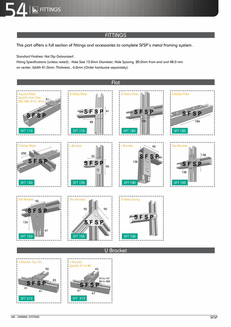
Uni - Channel SyStemS SFSP
54 FittinGS
this part offers a full section of fittings and accessories to complete SFSP’s metal framing system .
Standard Finishes: hot Dip Galvanized .
Fitting Specifications (unless noted) : hole Size 13.0mm Diameter; hole Spacing 20.0mm from end and 48.0 mm
on center; Width 41.0mm; thickness , 6.0mm (Order hardware separately).
Flat
U Bracket
41
41
232
90
136
41
54
23
4141
41
88
90
90
9090
43
43 for C4182 for B2B
4747
138
90
138
184
138
138
Square Plate Specify hole Size m6, m8, m10, m12
5 holes Plate
Flat Bracket
U Bracket top hat
2 holes Plate
l Bracket
Flat Bracket
U Bracket Specify 41 or 82
3 holes Plate
l Bracket
3 holes Swing
4 holes Plate
tee Bracket
FittinGS
SFt 110
SFt 130
SFt 150
SFt 610
SFt 115
SFt 135
SFt 155
SFt 615
SFt 120
SFt 140
SFt 160
SFt 125
SFt 145

Uni - Channel SyStemSSFSP
55FittinGS
angular
S
h
S
h
angle Bracket Specify 30° or 45°or 60°
angle Bracket Specify 30° or 45° or 60°
Wings
90˚ Degree
- Standard Finishes : Black,hot Dip Galvanized .
- Fitting Specifications (unless noted) : hole Size 13.0mm Diameter; hole Spacing 20.0mm from end and 48.0 mm on center;
Width 41.0mm; thickness , 6.0mm (Order hardware separately).
41
57
42
138
41
104
9847
41
138
51
41104
89
47 47
98
4043
4747
104
104
90° l Bracket
90° Bracket
90° angle tee left hand
90° l Bracket
90° Delta Bracket large
90° angle tee
90° long Bracket
90° Delta Bracket Small 90° heavy duty bracket
Channel tee Bracket
90° Bracket
SFt 510 SFt 515
SFt 210
SFt 230
SFt 310
SFt 215
SFt 235
SFt 315
SFt 220
SFt 240
SFt 320
SFt 225
SFt 245
16 46
90
98
13mm

Uni - Channel SyStemS SFSP
56 FittinGS
100
100
60
136
65
120
200
10060
200
100
100
136
65
200
100
200
100
200
100
4040
820
100
60
Post Base
Base Plate with Single Fix
Base Plate with Double Fix
Base Plate with Double Channel
Base Plate with Double Channel Double Fix
SFt 340
SFt 345
SFt 350
SFt 355
65
120 60
2040
8140
10020 20
100
20 2060100
100
100
41
408
60
20140
50 50 2020
120
8
6040
208
60
100100
136
120
65
200
60
100
200
100
100

aCCeSSORieS

Uni - Channel SyStemS SFSP
58 aCCeSSOiReS
DinZinc Plated for bolt Stainless Steel for
bolt
D
(mm)
d
(mm)
s
(mm)
440 m6 - 22 6.6 2
9021 m8 m8 24 8.4 2
9021 m10 m10 30 10.5 2.5
440 m12 - 45 13.5 4
9021 m12 m12 37 13 3
9021 m16 m16 50 17 3
Zinc Plated for bolt Stainless Steel for boltD
(mm)
d
(mm)
s
(mm)
m6 m6 12 6.4 1.6
m8 m8 16 8.4 1.6
m10 m10 21 10.5 2
m12 m12 24 13 2.5
m16 m16 30 17 3
Fully threaded Rods Grade 4.6 Din 975
S
m
S
d
D
S
d
D
Zinc PlatedThread - ZP
Zinc Platedfor bolt - ZP
Zinc PlatedDimension- ZP
D
[mm]
D
[mm]
S/mDIN
[mm]
SDIN
[mm]
S/mISO
[mm]
SEN
[mm]
e
[mm]
d
[mm]
d
[mm]
s
[mm]
s
[mm]
Length
[mm]
Load
cap.
[kN]
Threaded Rods, Hexagon Head Bol ts, Nuts, Washers
FR AMI NG SY STEM S ACC ESSORI ES
Order Example : TR - ZP - M 12 × 1000
Order Example : HB - ZP - M 12 × 1000
Order Example: WA - ZP - M 12 - DIN 9021
Order Example: WA - ZP - M 12 - DIN 125
DIN
22
24
30
45
37
50
12
16
21
24
30
10/ 5
13/6,5
17/ 8
19/10
24/13
10
13
17
19
24
18
24
10
13
16
10/ 6
13/7,5
16/ 9,5
18/12
24/15,5
11,5
15,0
19,6
21,9
27,7
6,6
8,4
10,5
13,5
13
17
6,4
8,4
10,5
13
17
2
2
2,5
4
3
3
1,6
1,6
2
2,5
3
1000
1000
1000
1000
1000
2,2
4,0
6,4
12,9
17,3
M 6
M 8
M 10
M 12
M 16
M 6 x 12
M 6 x 25
M 8 x 25
M 8 x 40
M 10 x 20
M 10 x 30
M 10 x 45
M 10 x 60
M 10 x 70
M 12 x 22
M 12 x 25
M 12 x 30
M 12 x 40
M 12 x 50
M 12 x 60
M 12 x 80
M 12 x 90
M 16 x 40
M 16 x 60
M 16 x 90
M 8 x 25
M 10 x 30
M 10 x 45
M 12 x 25
M 12 x 30
M 12 x 40
M 12 x 60
M 12 x 80
M 16 x 40
M 16 x 60
M 16 x 90
M 6
M 8
M 10
M 12
M 16
M 6
M 8
M 10
M 12
M 16
440
9021
9021
440
9021
9021
M 6
M 8
M 10
M 12
M 12
M 16
M 6
M 8
M 10
M 12
M 16
M 8
M 10
M 12
M 16
M 6
M 8
M 10
M 12
M 16
M 6
M 8
M 10
M 12
M 16
Stainless SteelThread
Zinc PlatedThread - ZP
Stainless SteelThread
Stainless Steelfor bolt
Zinc Platedfor bolt - ZP
Stainless Steelfor bolt
Stainless SteelDimension
Material & Finishes Codes
( S. 53)
= h.d. galvanised, strength grade 4.6
= electroplated, 4.6
= , 8.8
= Stainless steel grade A4-50
strength grade
h.d. galvanised strength grade
= electroplated, strength grade 8.8
= Stainless steel grade A4-70
= Stainless steel grade A2-50
= Stainless steel grade A2-70
= Stainless steel W1.4529 HCR-50
fv
gv
fv 8.8
A4-50
gv 8.8
A4-70
A2-50
A2-70
HCR
e
S
Zinc Plated thread length(mm)
load cap.(Kn)
m6 2000/3000 2.2
m8 2000/3000 4.0
m10 2000/3000 6.4
m12 2000/3000 12.9
m16 2000/3000 17.3
Order example : StR - m 12
threaded Rod (StR)Din 975
Square Washers SSW
h.D. Glavanized for Bolt Stainless Steel for Bolta x b x d
(mm)
m10 m10 40 x 40 x 5
m12 m12 40 x 40 x 5
m16 m16 40 x 40 x 5
m6 m6 40 x 40 x 6
m10 m10 40 x 40 x 6
m12 m12 40 x 40 x 6
FR AMI NG SY STEM S ACC ESSORI ES
s
L
D
L
Loadcap.
[kN]
Order example:
Order example:
Loadcap.
[kN]
S
[mm]
L
[mm]
D
[mm]
L
[mm]
10/10
12/14
13/16
16/20
21/25
26/32
13
17
22
15
20
25
30
40
50
40
40
50
2,2
4,0
6,4
9,3
17,3
27,0
6,4
9,3
17,3
M 6
M 8
M 10
M 12
M 16
M 20
M 10
M 12
M 16
M 6
M 8
M 10
M 12
M 16
M 20
M 10
M 12
M 16
CS - GV - M 16
HRC - GV - M 12
Coupler Sleeves, Square washers ,Sleeve Anchor ,Throught Anchor .......
Throught Anchor
Sleeve Anchor
b
da
b
d
a
Order Example: SW 41/41 - HDG - M 12
40 x 40 x 5
40 x 40 x 5
40 x 40 x 5
40 x 40 x 6
40 x 40 x 6
40 x 40 x 6
a x b x d
[mm]
M 10
M 12
M 16
M 6
M 10
M 12
M 6
M 10
M 12
M 10
M 12
M 16
ElectroplatedThread - GV
ElectroplatedThread - GV
Stainless SteelThread
Stainless SteelThread
H.D. Galvanisedfor Bolts - HDG
Stainless Steelfor Bolts
Yellow zinc plated SteelThread (Zn)
L (mm)
Order example:
M 6
M 8
M 10
M 12
45
50
60
74
M 6
M 8
M 10
STM - Zn - M 12
Stainless Steel
Thread
Drill
(mm)
10
12
15
18
Min.Drill hole
(mm)
55
60
75
90
M 6
M 8
M 10
Stainless Steel
Thread
Yellow zinc plated SteelThread (Zn)
Screwx Length (mm)
Order example:
M 6
M 8
M 10
M 12
6x50
8x60
10x80
12x90
STMH - Zn - M 12
S max fixing(mm)
5
10
20
25
Yellow zinc plated Steel Thread (Zn)
10
25
45
75
10.3
12.2
17.1
25.3
9.6
17.5
27.8
40.5
M 6
M 8
M 10
M 12
TypeMax Torque
(mm)Pull Out
Shear
8
19
38
9.5
14
19
8.4
15.4
24.4
Max Torque(mm)
Pull Out
Shear
Stainless SteelThread
Pull-out values in KN -concrete R 250kg/cm2
its is advisable to apply safty factor in consideration of the various ways of employment
(1KN=100kg)
Square Washers (SSW)
SSW 40/40for all channels 41/21 Series
SSW 41/41for all channels41/41 Series
Order example: SSW 41/41 - m 12
Round Washers Din 440,Din 9021
Washers (SRW)Din 440,Din 9021
Order example: SRW - m 12 - Din 9021
Round Washers Din 125
Washers (SRW)Din 125
Order example: SRW - m 12 - Din 125
S
m
S
d
D
S
d
D
Zinc PlatedThread - ZP
Zinc Platedfor bolt - ZP
Zinc PlatedDimension- ZP
D
[mm]
D
[mm]
S/mDIN
[mm]
SDIN
[mm]
S/mISO
[mm]
SEN
[mm]
e
[mm]
d
[mm]
d
[mm]
s
[mm]
s
[mm]
Length
[mm]
Load
cap.
[kN]
Threaded Rods, Hexagon Head Bol ts, Nuts, Washers
FR AMI NG SY STEM S ACC ESSORI ES
Order Example : TR - ZP - M 12 × 1000
Order Example : HB - ZP - M 12 × 1000
Order Example: WA - ZP - M 12 - DIN 9021
Order Example: WA - ZP - M 12 - DIN 125
DIN
22
24
30
45
37
50
12
16
21
24
30
10/ 5
13/6,5
17/ 8
19/10
24/13
10
13
17
19
24
18
24
10
13
16
10/ 6
13/7,5
16/ 9,5
18/12
24/15,5
11,5
15,0
19,6
21,9
27,7
6,6
8,4
10,5
13,5
13
17
6,4
8,4
10,5
13
17
2
2
2,5
4
3
3
1,6
1,6
2
2,5
3
1000
1000
1000
1000
1000
2,2
4,0
6,4
12,9
17,3
M 6
M 8
M 10
M 12
M 16
M 6 x 12
M 6 x 25
M 8 x 25
M 8 x 40
M 10 x 20
M 10 x 30
M 10 x 45
M 10 x 60
M 10 x 70
M 12 x 22
M 12 x 25
M 12 x 30
M 12 x 40
M 12 x 50
M 12 x 60
M 12 x 80
M 12 x 90
M 16 x 40
M 16 x 60
M 16 x 90
M 8 x 25
M 10 x 30
M 10 x 45
M 12 x 25
M 12 x 30
M 12 x 40
M 12 x 60
M 12 x 80
M 16 x 40
M 16 x 60
M 16 x 90
M 6
M 8
M 10
M 12
M 16
M 6
M 8
M 10
M 12
M 16
440
9021
9021
440
9021
9021
M 6
M 8
M 10
M 12
M 12
M 16
M 6
M 8
M 10
M 12
M 16
M 8
M 10
M 12
M 16
M 6
M 8
M 10
M 12
M 16
M 6
M 8
M 10
M 12
M 16
Stainless SteelThread
Zinc PlatedThread - ZP
Stainless SteelThread
Stainless Steelfor bolt
Zinc Platedfor bolt - ZP
Stainless Steelfor bolt
Stainless SteelDimension
Material & Finishes Codes
( S. 53)
= h.d. galvanised, strength grade 4.6
= electroplated, 4.6
= , 8.8
= Stainless steel grade A4-50
strength grade
h.d. galvanised strength grade
= electroplated, strength grade 8.8
= Stainless steel grade A4-70
= Stainless steel grade A2-50
= Stainless steel grade A2-70
= Stainless steel W1.4529 HCR-50
fv
gv
fv 8.8
A4-50
gv 8.8
A4-70
A2-50
A2-70
HCR
e
S
FR AMI NG SY STEM S ACC ESSORI ES
s
L
D
L
Loadcap.
[kN]
Order example:
Order example:
Loadcap.
[kN]
S
[mm]
L
[mm]
D
[mm]
L
[mm]
10/10
12/14
13/16
16/20
21/25
26/32
13
17
22
15
20
25
30
40
50
40
40
50
2,2
4,0
6,4
9,3
17,3
27,0
6,4
9,3
17,3
M 6
M 8
M 10
M 12
M 16
M 20
M 10
M 12
M 16
M 6
M 8
M 10
M 12
M 16
M 20
M 10
M 12
M 16
CS - GV - M 16
HRC - GV - M 12
Coupler Sleeves, Square washers ,Sleeve Anchor ,Throught Anchor .......
Throught Anchor
Sleeve Anchor
b
da
b
d
a
Order Example: SW 41/41 - HDG - M 12
40 x 40 x 5
40 x 40 x 5
40 x 40 x 5
40 x 40 x 6
40 x 40 x 6
40 x 40 x 6
a x b x d
[mm]
M 10
M 12
M 16
M 6
M 10
M 12
M 6
M 10
M 12
M 10
M 12
M 16
ElectroplatedThread - GV
ElectroplatedThread - GV
Stainless SteelThread
Stainless SteelThread
H.D. Galvanisedfor Bolts - HDG
Stainless Steelfor Bolts
Yellow zinc plated SteelThread (Zn)
L (mm)
Order example:
M 6
M 8
M 10
M 12
45
50
60
74
M 6
M 8
M 10
STM - Zn - M 12
Stainless Steel
Thread
Drill
(mm)
10
12
15
18
Min.Drill hole
(mm)
55
60
75
90
M 6
M 8
M 10
Stainless Steel
Thread
Yellow zinc plated SteelThread (Zn)
Screwx Length (mm)
Order example:
M 6
M 8
M 10
M 12
6x50
8x60
10x80
12x90
STMH - Zn - M 12
S max fixing(mm)
5
10
20
25
Yellow zinc plated Steel Thread (Zn)
10
25
45
75
10.3
12.2
17.1
25.3
9.6
17.5
27.8
40.5
M 6
M 8
M 10
M 12
TypeMax Torque
(mm)Pull Out
Shear
8
19
38
9.5
14
19
8.4
15.4
24.4
Max Torque(mm)
Pull Out
Shear
Stainless SteelThread
Pull-out values in KN -concrete R 250kg/cm2
its is advisable to apply safty factor in consideration of the various ways of employment
(1KN=100kg)
S
m
S
d
D
S
d
D
Zinc PlatedThread - ZP
Zinc Platedfor bolt - ZP
Zinc PlatedDimension- ZP
D
[mm]
D
[mm]
S/mDIN
[mm]
SDIN
[mm]
S/mISO
[mm]
SEN
[mm]
e
[mm]
d
[mm]
d
[mm]
s
[mm]
s
[mm]
Length
[mm]
Load
cap.
[kN]
Threaded Rods, Hexagon Head Bol ts, Nuts, Washers
FR AMI NG SY STEM S ACC ESSORI ES
Order Example : TR - ZP - M 12 × 1000
Order Example : HB - ZP - M 12 × 1000
Order Example: WA - ZP - M 12 - DIN 9021
Order Example: WA - ZP - M 12 - DIN 125
DIN
22
24
30
45
37
50
12
16
21
24
30
10/ 5
13/6,5
17/ 8
19/10
24/13
10
13
17
19
24
18
24
10
13
16
10/ 6
13/7,5
16/ 9,5
18/12
24/15,5
11,5
15,0
19,6
21,9
27,7
6,6
8,4
10,5
13,5
13
17
6,4
8,4
10,5
13
17
2
2
2,5
4
3
3
1,6
1,6
2
2,5
3
1000
1000
1000
1000
1000
2,2
4,0
6,4
12,9
17,3
M 6
M 8
M 10
M 12
M 16
M 6 x 12
M 6 x 25
M 8 x 25
M 8 x 40
M 10 x 20
M 10 x 30
M 10 x 45
M 10 x 60
M 10 x 70
M 12 x 22
M 12 x 25
M 12 x 30
M 12 x 40
M 12 x 50
M 12 x 60
M 12 x 80
M 12 x 90
M 16 x 40
M 16 x 60
M 16 x 90
M 8 x 25
M 10 x 30
M 10 x 45
M 12 x 25
M 12 x 30
M 12 x 40
M 12 x 60
M 12 x 80
M 16 x 40
M 16 x 60
M 16 x 90
M 6
M 8
M 10
M 12
M 16
M 6
M 8
M 10
M 12
M 16
440
9021
9021
440
9021
9021
M 6
M 8
M 10
M 12
M 12
M 16
M 6
M 8
M 10
M 12
M 16
M 8
M 10
M 12
M 16
M 6
M 8
M 10
M 12
M 16
M 6
M 8
M 10
M 12
M 16
Stainless SteelThread
Zinc PlatedThread - ZP
Stainless SteelThread
Stainless Steelfor bolt
Zinc Platedfor bolt - ZP
Stainless Steelfor bolt
Stainless SteelDimension
Material & Finishes Codes
( S. 53)
= h.d. galvanised, strength grade 4.6
= electroplated, 4.6
= , 8.8
= Stainless steel grade A4-50
strength grade
h.d. galvanised strength grade
= electroplated, strength grade 8.8
= Stainless steel grade A4-70
= Stainless steel grade A2-50
= Stainless steel grade A2-70
= Stainless steel W1.4529 HCR-50
fv
gv
fv 8.8
A4-50
gv 8.8
A4-70
A2-50
A2-70
HCR
e
S
FRaminG SyStem aCCeSSORieSthreaded Rods, hexagon head Bolts, hexagon nuts, Washers

Uni - Channel SyStemSSFSP
59aCCeSSOiReS
electroplated thread Stainless Steel thread
D
(mm)
L
(mm)
Loadcap.
(KN)
M6 M6 10/10 15 2.2
M8 M8 12/14 20 4.0
M10 M10 13/16 25 6.4
M12 M12 16/20 30 9.3
M16 M16 21/25 40 17.3
M20 M20 26/32 50 27.0
Coupler Sleeves Rounded
Coupler Sleeves (SCS)
Order example: SCS - m 16
electroplated thread Stainless Steel thread
S
(mm)
L
(mm)
Loadcap.
(KN)
M10 M10 13 40 6.4
M12 M12 17 40 9.3
M16 M16 22 50 17.3
hexagonal Rod Couplerhexagonal Rod Coupler with view hole (ShR)
Order example: ShR - ZP - m 12
machine hexhead Bolts Din 933, Din 24017
S
m
S
d
D
S
d
D
Zinc PlatedThread - ZP
Zinc Platedfor bolt - ZP
Zinc PlatedDimension- ZP
D
[mm]
D
[mm]
S/mDIN
[mm]
SDIN
[mm]
S/mISO
[mm]
SEN
[mm]
e
[mm]
d
[mm]
d
[mm]
s
[mm]
s
[mm]
Length
[mm]
Load
cap.
[kN]
Threaded Rods, Hexagon Head Bol ts, Nuts, Washers
FR AMI NG SY STEM S ACC ESSORI ES
Order Example : TR - ZP - M 12 × 1000
Order Example : HB - ZP - M 12 × 1000
Order Example: WA - ZP - M 12 - DIN 9021
Order Example: WA - ZP - M 12 - DIN 125
DIN
22
24
30
45
37
50
12
16
21
24
30
10/ 5
13/6,5
17/ 8
19/10
24/13
10
13
17
19
24
18
24
10
13
16
10/ 6
13/7,5
16/ 9,5
18/12
24/15,5
11,5
15,0
19,6
21,9
27,7
6,6
8,4
10,5
13,5
13
17
6,4
8,4
10,5
13
17
2
2
2,5
4
3
3
1,6
1,6
2
2,5
3
1000
1000
1000
1000
1000
2,2
4,0
6,4
12,9
17,3
M 6
M 8
M 10
M 12
M 16
M 6 x 12
M 6 x 25
M 8 x 25
M 8 x 40
M 10 x 20
M 10 x 30
M 10 x 45
M 10 x 60
M 10 x 70
M 12 x 22
M 12 x 25
M 12 x 30
M 12 x 40
M 12 x 50
M 12 x 60
M 12 x 80
M 12 x 90
M 16 x 40
M 16 x 60
M 16 x 90
M 8 x 25
M 10 x 30
M 10 x 45
M 12 x 25
M 12 x 30
M 12 x 40
M 12 x 60
M 12 x 80
M 16 x 40
M 16 x 60
M 16 x 90
M 6
M 8
M 10
M 12
M 16
M 6
M 8
M 10
M 12
M 16
440
9021
9021
440
9021
9021
M 6
M 8
M 10
M 12
M 12
M 16
M 6
M 8
M 10
M 12
M 16
M 8
M 10
M 12
M 16
M 6
M 8
M 10
M 12
M 16
M 6
M 8
M 10
M 12
M 16
Stainless SteelThread
Zinc PlatedThread - ZP
Stainless SteelThread
Stainless Steelfor bolt
Zinc Platedfor bolt - ZP
Stainless Steelfor bolt
Stainless SteelDimension
Material & Finishes Codes
( S. 53)
= h.d. galvanised, strength grade 4.6
= electroplated, 4.6
= , 8.8
= Stainless steel grade A4-50
strength grade
h.d. galvanised strength grade
= electroplated, strength grade 8.8
= Stainless steel grade A4-70
= Stainless steel grade A2-50
= Stainless steel grade A2-70
= Stainless steel W1.4529 HCR-50
fv
gv
fv 8.8
A4-50
gv 8.8
A4-70
A2-50
A2-70
HCR
e
S
hex head Bolt (ShB)Din 933 or en 24017(without nut)
Order example : ShB - m 12
Zinc Plated Dimension Stainless Steel DimensionS
Din(mm)
Sen
(mm)
m 6 x 12 -10 10
m 6 x 25 -
m 8 x 25 m 8 x 2513 13
m 8 x 40 -
m 10 x 20 -
17 16
m 10 x 30 m 10 x 30
m 10 x 45 m 10 x 45
m 10 x 60 -
m 10 x 70 -
m 12 x 22 -
19 18
m 12 x 25 m 12 x 25
m 12 x 30 m 12 x 30
m 12 x 40 m 12 x 40
m 12 x 50 -
m 12 x 60 m 12 x 60
m 12 x 80 m 12 x 80
m 12 x 90 -
m 16 x 40 m 16 x 40
24 24m 16 x 60 m 16 x 60
m 16 x 90 m 16 x 90
hexagon nuts Din 934, Din en 24032S
m
S
d
D
S
d
D
Zinc PlatedThread - ZP
Zinc Platedfor bolt - ZP
Zinc PlatedDimension- ZP
D
[mm]
D
[mm]
S/mDIN
[mm]
SDIN
[mm]
S/mISO
[mm]
SEN
[mm]
e
[mm]
d
[mm]
d
[mm]
s
[mm]
s
[mm]
Length
[mm]
Load
cap.
[kN]
Threaded Rods, Hexagon Head Bol ts, Nuts, Washers
FR AMI NG SY STEM S ACC ESSORI ES
Order Example : TR - ZP - M 12 × 1000
Order Example : HB - ZP - M 12 × 1000
Order Example: WA - ZP - M 12 - DIN 9021
Order Example: WA - ZP - M 12 - DIN 125
DIN
22
24
30
45
37
50
12
16
21
24
30
10/ 5
13/6,5
17/ 8
19/10
24/13
10
13
17
19
24
18
24
10
13
16
10/ 6
13/7,5
16/ 9,5
18/12
24/15,5
11,5
15,0
19,6
21,9
27,7
6,6
8,4
10,5
13,5
13
17
6,4
8,4
10,5
13
17
2
2
2,5
4
3
3
1,6
1,6
2
2,5
3
1000
1000
1000
1000
1000
2,2
4,0
6,4
12,9
17,3
M 6
M 8
M 10
M 12
M 16
M 6 x 12
M 6 x 25
M 8 x 25
M 8 x 40
M 10 x 20
M 10 x 30
M 10 x 45
M 10 x 60
M 10 x 70
M 12 x 22
M 12 x 25
M 12 x 30
M 12 x 40
M 12 x 50
M 12 x 60
M 12 x 80
M 12 x 90
M 16 x 40
M 16 x 60
M 16 x 90
M 8 x 25
M 10 x 30
M 10 x 45
M 12 x 25
M 12 x 30
M 12 x 40
M 12 x 60
M 12 x 80
M 16 x 40
M 16 x 60
M 16 x 90
M 6
M 8
M 10
M 12
M 16
M 6
M 8
M 10
M 12
M 16
440
9021
9021
440
9021
9021
M 6
M 8
M 10
M 12
M 12
M 16
M 6
M 8
M 10
M 12
M 16
M 8
M 10
M 12
M 16
M 6
M 8
M 10
M 12
M 16
M 6
M 8
M 10
M 12
M 16
Stainless SteelThread
Zinc PlatedThread - ZP
Stainless SteelThread
Stainless Steelfor bolt
Zinc Platedfor bolt - ZP
Stainless Steelfor bolt
Stainless SteelDimension
Material & Finishes Codes
( S. 53)
= h.d. galvanised, strength grade 4.6
= electroplated, 4.6
= , 8.8
= Stainless steel grade A4-50
strength grade
h.d. galvanised strength grade
= electroplated, strength grade 8.8
= Stainless steel grade A4-70
= Stainless steel grade A2-50
= Stainless steel grade A2-70
= Stainless steel W1.4529 HCR-50
fv
gv
fv 8.8
A4-50
gv 8.8
A4-70
A2-50
A2-70
HCR
e
S
hexagon nut (Shn)Din 934 or iSO 4032(= Din en 24032)
Zinc Plated thread Stainless Steel threadS/mDin
(mm)
S/miSO
(mm)
e
(mm)
m6 m6 10/5 10/6 11.5
m8 m8 13/6.5 13/7.5 15.0
m10 m10 17/8 16/9.5 19.6
m12 m12 19/10 18/12 21.9
m16 m16 24/13 24/15.5 27.7
Order example : Shn - m 12
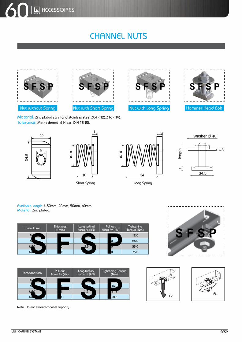
Uni - Channel SyStemS SFSP
60 aCCeSSOiReS
nut without Spring nut with Short Spring nut with long Spring hammer head Bolt
material: Zinc plated steel and stainless steel 304 (a2),316 (a4).tolerance: metric thread 6 h acc. Din 13-20.
t t
0.1
8
10
20
34.5
M
0.1
8
34 FL
t t
0.1
8
10
20
34.5
M
0.1
8
34 FL
t t
0.1
8
10
20
34.5
M
0.1
8
34 FL
Washer Ø 40
34.5
3
tle
ngth
FvFL
threaded Size Pull outForce Fv (kn)
longitudinalForce Fl (kn)
tightening torque(nm)
m6 5.0 0.3 6.5
m8 6.0 0.6 16.0
m10 7.0 1.2 31.5
m12 7.0 1.7 50.0
note: Do not exceed channel capacity
available length: l 30mm, 40mm, 50mm, 60mm.material: Zinc plated.
thread Size thicknesst (mm)
longitudinal Force Fl (kn)
Pull outForce Fv (kn)
tighteningtorque (nm)
m6 5.0 1.0 5.0 12.0
m8 6.0 2.4 6.0 28.0
m10 8.0 3.5 7.0 55.0
m12 10.0 5.0 9.0 75.0
Short Spring long Spring
FvFl
Channel nUtS

Uni - Channel SyStemSSFSP
61aCCeSSOiReS
insert the spring nut anywhere along the continuous slotted channel. the rounded nut ends permit easy insertion.
a 90° clockwise turn aligns the grooves in the nut with the inturned edges of the channel. the need for drilling holes is eliminated.
additional channel sections can now be bolted to the fitting already in place by following procedure described in steps 1–3.
tightening with a wrench locks the serrated teeth of the nut into the inturned edges of the channel, to complete a strong, vise-like connection.
no Welding , no Drilling , no Special tools, Strong, Fast, economical and adjustable.
insert the bolt through the fitting and into the springnut. (See illustration 5 for end view showing the nut in place)
hex-head bolt connects fitting to channel as it is threaded into spring nut.
Chamfer in the nut eases starting of the bolt. nut teeth make a strong, vise-like grip when tightened against the inturned channel edges.
Channel edges and the nut’s tapered grooves act as guides to provide fool-proof alignment of connection.
nut teeth grip the channel’s inturned edges, tying the channel sides together in a “box” configuration for added strength.
Spring allows precision placement anywhere along channel length, then holds the nut in position while the connection is completed.
inStallatiOn & FeatUReS
1
2
3
4 5
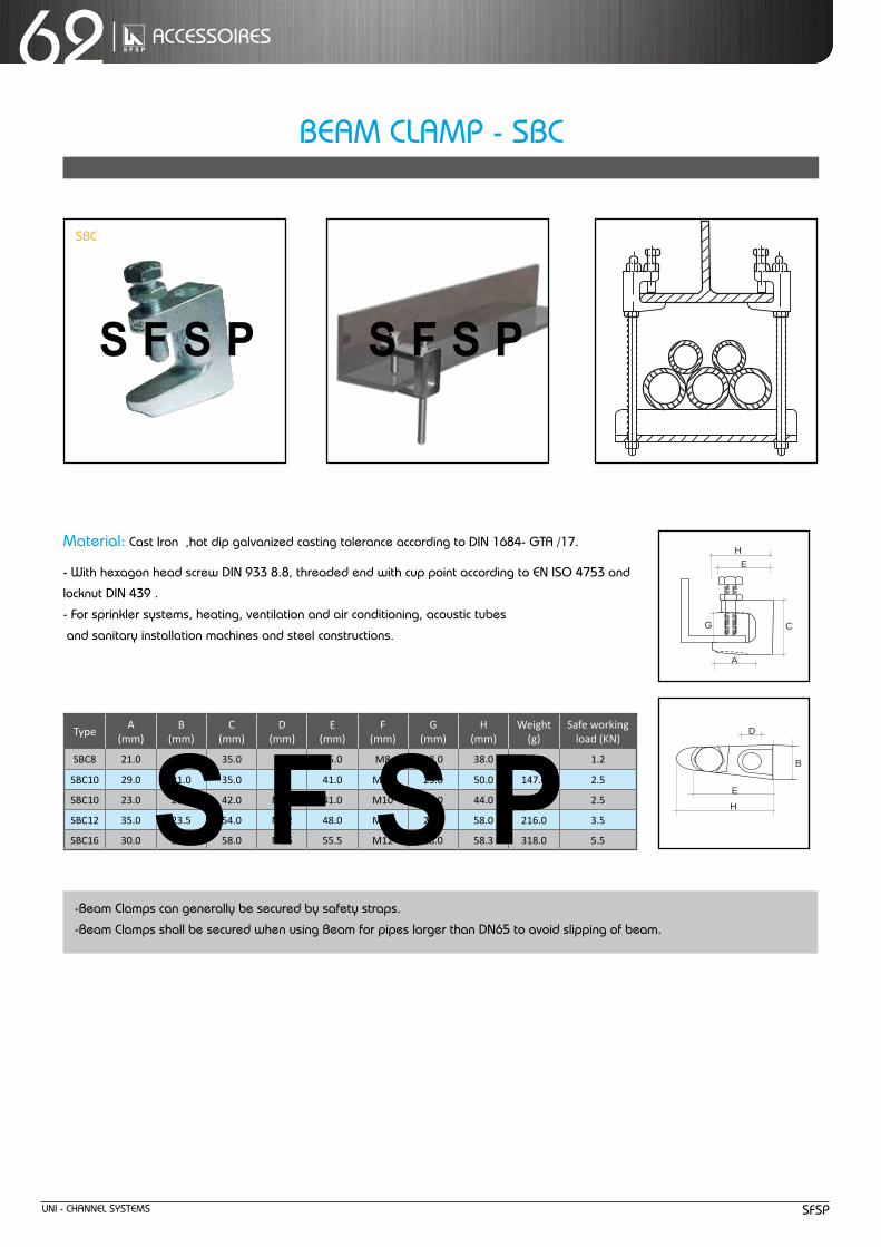
Uni - Channel SyStemS SFSP
62 aCCeSSOiReS
26
This section offers a full selection of fittings and accessories to complete SFSP’s metalframing system.
FITTINGS
STANDARD FINISHES: Hot Dip Galvanized .
FT 145
FT 150 FT 155
FITTING SPECIFICATIONS (unless noted): Hole Size—13.0mm Diameter; Hole Spacing— 20.0mm from end and48.0 mm on center; Width— 41.0mm; Thickness— 6.0mm (Order hardware separately)
FT 115FT 110 FT 120 FT 125
FT 130 FT 140
Square Plate Specify Hole Size M6,M8,M10,M12
2 Holes Plate 3 Holes Plate 4 Holes Plate
5 Holes Plate L Bracket Tee Bracket
Flat Bracket Flat Bracket
L Bracket
M6 25MM 25MM
LN 625LN 830 M8
M10 40MM40MM
LN 1040LN 1240
Part No. HoleH
Bolt Grade 8.8
LN 1650M12M16 50MM
A35
35454545
B1919
252525
C38385050
50
D3535414141
E1919212121
Beam Clamp Zinc Plated
FT 160
3 Holes Swing
E
D
CB
EH
G
H
A
FT 135
41
41
88138 184
41
138
138232 90
90
136
41
90
13890
9090
[email protected] · www.bts-saarburg.de · Tel.: +49 6581 9168-0 · Fax: +49 6581 9168-79
material: Cast iron ,hot dip galvanized casting tolerance according to Din 1684- Gta /17.
- With hexagon head screw Din 933 8.8, threaded end with cup point according to en iSO 4753 and
locknut Din 439 .
- For sprinkler systems, heating, ventilation and air conditioning, acoustic tubes
and sanitary installation machines and steel constructions.
TypeA
(mm)B
(mm)C
(mm)D
(mm)E
(mm)F
(mm)G
(mm)H
(mm)Weight
(g)Safe working
load (KN)
SBC8 21.0 19.0 35.0 M8 35.0 M8 18.0 38.0 81.0 1.2
SBC10 29.0 21.0 35.0 M8 41.0 M10 23.0 50.0 147.0 2.5
SBC10 23.0 21.0 42.0 M10 41.0 M10 20.0 44.0 143.0 2.5
SBC12 35.0 23.5 54.0 M12 48.0 M10 26.0 58.0 216.0 3.5
SBC16 30.0 29.5 58.0 M16 55.5 M12 28.0 58.3 318.0 5.5
-Beam Clamps can generally be secured by safety straps.
-Beam Clamps shall be secured when using Beam for pipes larger than Dn65 to avoid slipping of beam.
SBC
Beam ClamP - SBC

CantileveRS
& BeamS

Uni - Channel SyStemS SFSP
64 CantileveRS & BeamS
CantileveR aRm BRaCKetS - SCa
CCh421 41x21x2.5
* Given loads are always [Kn] “ allowable characteristic live load “
Base plate : height (h) x width (b) x thickness (t) 140 50 10 - in the case of concrete support, use anchor m16.- in the case of C-channel frame, use bolt and spring m8.
** Connection force (pull out force) : 7.5 (Kn)
F1
1/2 A 1/2 A
or F2
Length A (mm)
h
2525
h-50
b t
FD
Fz
Fv =F1 + F2
CCh441 41x41x2.5
Base plate : height (h) x width (b) x thickness (t) 120 50 8
- in the case of concrete support, use anchor m10.- in the case of C-channel frame, use bolt and spring nut m8.
** Connection force (pull out force) : 3.1 (Kn)
F2
F2
F1
F1
length allowable loada (mm) F1* F2* Fz**
150 1.10 0.60 3.10
300 0.60 0.30 3.10
450 0.40 0.20 3.10
600 0.30 0.10 3.10
700 0.20 0.10 3.10
800 0.20 0.10 3.10
900 0.20 0.10 3.10
1000 0.20 0.10 3.10
length allowable loada (mm) F1* F2* Fz**
150 3.10 1.50 7.50
300 1.50 0.80 7.50
450 1.00 0.50 7.50
600 0.80 0.40 7.50
700 0.70 0.30 7.50
800 0.60 0.30 7.50
900 0.50 0.30 7.50
1000 0.50 0.20 7.50
a
a
F1
F1
F2
F2
1.20
1.00
0.80
0.60
0.40
0.20
0.00150 300 450 600 700 800 900 1000
length mm
Kn
length mm
Kn
3.50
3.00
2.50
2.00
1.50
1.00
0.50
0.00150 300 450 600 700 800 900 1000

Uni - Channel SyStemSSFSP
65CantileveRS & BeamS
Base plate : height (h) x width (b) x thickness (t) 140 50 10
- in the case of concrete support, use anchor m12.- in the case of C-channel frame, use bolt and spring nut m8.
** Connection force (pull out force) : 4.8 (Kn)
CCh422 41x21x2.5 B2B
* Given loads are always [Kn] “ allowable characteristic live load “
F1
1/2 A 1/2 A
or F2
Length A (mm)
h
b t
2525
h-50
FD
Fv =F1 + F2
Fz
CCh442 41x41x2.5 B2B
CantileveR aRm BRaCKet B2B - SCa
Base plate : height (h) x width (b) x thickness (t) 180 60 12
in the case of concrete support, use anchor m16.in the case of C-channel frame, use spring nut m10.
** Connection force (pull out force) : 8.3(Kn)
length allowable loada (mm) F1* F2* Fz**
150 2.50 1.30 4.80
300 1.30 0.60 8.48
450 0.80 0.40 4.80
600 0.60 0.30 4.80
700 0.50 0.30 4.80
800 0.50 0.20 4.80
900 0.40 0.20 4.80
1000 0.40 0.20 4.80
length allowable loada (mm) F1* F2* Fz**
150 7.00 3.50 8.30
300 3.50 1.80 8.30
450 2.30 1.20 8.30
600 1.80 0.90 8.30
700 1.50 0.80 8.30
800 1.30 0.70 8.30
900 1.20 0.60 8.30
1000 1.10 0.50 8.30
F2
F2
F1
F1
a
a
F1 F2
F1
F2
length mm
length mm
KnKn
3.00
2.50
2.00
1.50
1.00
0.50
0.00150 300 450 600 700 800 900 1000
150 300 450 600 700 800 900 1000
8.007.006.005.004.003.002.001.000.00

Uni - Channel SyStemS SFSP
66 CantileveRS & BeamS
U - Support
i - Support
Wall Bracket
200140
100
8042
25
70
200140
100
8042
25
70
13x30
13x30
13x30
13x30
5
5
200140
100
8042
25
70
200140
100
8042
25
70
13x30
13x30
13x30
13x30
5
5
200140
100
8042
25
70
200140
100
8042
25
70
13x30
13x30
13x30
13x30
5
53000
3050
3200 3250
Order example: 3000 - length (l) - thickness (t) for more ordering details, please check pages (61-62)
U-Support with welded-on head plate200 x 100 x 5mm
U-Support with welded-on head plate200 x 100 x 5mm
5 mm thickness
for U-Support for i-Support
Order example: 3050 - length (l) - thickness (t) for more ordering details, please check pages (61-62)
Order example: 3200 - length (l) - thickness (t) for more ordering details, please check pages (61-62)
Order exampleitem (l) (t)3000 0200 5
Order exampleitem (l) (t)3050 0200 5
Order exampleitem (l) (t)3200 0210 5
head Plate
3100 200 x 100 x 5mm

Uni - Channel SyStemSSFSP
67CantileveRS & BeamS
Support connectors
Support plates
Clamping plates
Support clamps
3300
3400
Clamping angles
3550
angles
3600 3450
3350
Order example: 3300 - length (l) - thickness (t) for more ordering details, please check pages (61-62)
Order example: 3350 - length (l) - thickness (t) for more ordering details, please check pages (61-62)
Order exampleitem (l) (t)3300 0200 5
Order exampleitem (l) (t)3350 0200 5


SyStem eXamPleS

Uni - Channel SyStemS SFSP
70 SyStem eXamPleS
Suitable for pipes with nominal diameters up to 25 mm
Frame constructions: will be manufactured to your measurements
C-Channel
nut with spring
C-Channel with l Bracket
Base Plate with double fix
B2B Channel
Base Plate withDouble ChannelDouble Fix
l Bracket
C-Channel
Base Plate with double fix
Base Plate withDouble ChannelDouble Fix
B2B Channel
C-Channel
Base Plate with double fix
C-Channel FRaminG SyStemS 21X41
kg
C-Channel
l Bracket
21
41

Uni - Channel SyStemSSFSP
71SyStem eXamPleS
Suitable for pipes with nominal diameters up to 80 mm or 150 mm with short spans or agreed applications
kg
kg
kg
kg
kg
C-Channel
Base Plate with double fix
U Bracket
41
41
kg
l Bracket
C-Channel
Base Plate with double fix
angle fittings, fixing plates etc.
C-ChannelBase Plate with double fix
l Bracket
U Bracket
Delta Bracket
l Bracket
Base Plate with double fix
C-Channel
C-Channel
Base Plate with double fix
C-Channel FRaminG SyStemS 41X41

Uni - Channel SyStemS SFSP
72 SyStem eXamPleS
kg
kg
kg
kg
kg
kg
kg
kg
kg
kg
kg
kg
kg
kg
Support structures for heavy duty
Support structures for light duty
C-Channel
Base Plate with double fix
l Bracket

anChORS

Uni - Channel SyStemS SFSP
74 anChORS
heavy DUty anChORS General information
Fig.1
Fig.2
Fig.3
Fig.4Fig.4
Fig.3
Fig.2
Fig.1
Direction of loading
the direction of the applied load shall be considered to determine the most appropriate anchor .
the tension and shear components shall be less than the recommended load/design resistance in the direction concerned.
Slotted holes in FixtureWhen fixing anchors through slotted holes; it is important to ensure that there is an adequate surface contact between the washer
and the fixture to guarantee a positive clamping force.
if in doubt, a square plate washer with a thickness of 3mm or above would be recommended in place of the standard washer
supplied.
Diamond Drilled holes When holes are formed in the structure using a diamond drilling system; extra care is required to ensure the holes are thoroughly
cleaned by brushing and blowing for at least three times. also, to make a key for the anchor (particulary if a bonded anchor is
installed) the sides of the hole shall be roughened up by inserting a standard masonry bit into the hole attached to a hammer
action drilling machine.
a resin with minimal shrinkage shall be selected for diamond drilled holes.
tensile loadstensile loads are applied along the axis of fixing (see Fig.1).
Common examples include suspended ceiling applications and
the suspension of mechanical services, pipework, ductwork, etc.
Shear loadsShear loads act at right angles to the axis of fixing and directly
against the face of the structural material (see Fig.2).
Shear performance is governed mainly by the shear strength
of the bolt material and by the comperssive strength of the
supporting substrate.
Oblique / Combined loadsOblique loads are a combination of tension and shear
components (see Fig.3).
If the angle of the applied oblique load is within 10˚ of pure
tension or pure shear, the safe working load for that direction
may be assumed. Otherwise, the applied oblique load shall be
resolved into its shear and tensile components.
Offset loadsOffset loads act at right angles to the fixing axis but are offset
from the surface (see Fig.4).
in this situation, the deflection of the bolt due to bending needs
to be considered as well as the shear capacity of the anchor.

Uni - Channel SyStemSSFSP
75anChORS
technical Data:Recommended loads (non-cracked concrete C 20/25).
Setting Data:edge distance > 1,5 x h eff., distance between anchors > 3 x h eff. thickness of foundation > 2 x h eff.
installation Parmeters:h eff = effective anchorage depth.
type(order no)
tension load(Kn)
Shear load(Kn)
torque moment(nm)
Screw Grade
m6 2.5 2.3 10 4.6
m8 3.3 4.4 17 4.6
m10 4.7 6.5 34 4.6
m12 6.9 8.5 60 4.6
Size h eff.(mm)
edge DistanceC (mm)
Distance Betweenanchors S
(mm)
thickness ofFoundationhmin (mm)
Washer(Ø)
tightening torque (nm)
Spannersize (mm)
m6 40 60 120 100 12 x 1.6 10 10
m8 45 68 135 100 16 x 1.6 20 13
m10 55 83 165 110 20 x 2.0 40 17
m12 70 105 210 140 24 x 2.5 75 19
Bolt Size length exp.unit(mm)
Drill (Ø) (mm)
Drilling depth (mm)
h eff.(mm)
Usable length(mm)
Screw Ø x length (mm)
m6 45 10 55 40 5 m6 x 50
m8 50 12 60 45 10 m8 x 60
m10 60 15 80 55 20 m10 x 80
m12 75 18 90 70 25 m12 x 90
*for cracked Concrete we shall use 0,5 x this value (approximately)
Features:- Suitable for all screws or threaded bolts with metric thread.
- low energy impact, power-saving assembly.
- multiple removing and fixing.
- inside threaded anchor, allows great flexibility.
- Can use variable lengths and art of threaded rods or bolts.
- Small edge distance and small distance between anchors.
- Provide uniform load by tightening the screw or hexagon nut, the cone pulls
into the expansion anchor and tightens against the drilled hole.
- Suitable for use in concrete and natural stone.
typical applications:Cable trays, handrails, brackets, staircases, ladders, machines, window panels, base
plates, scaffoldings and frameworks .
FR AMI NG SY STEM S ACC ESSORI ES
s
L
D
L
Loadcap.
[kN]
Order example:
Order example:
Loadcap.
[kN]
S
[mm]
L
[mm]
D
[mm]
L
[mm]
10/10
12/14
13/16
16/20
21/25
26/32
13
17
22
15
20
25
30
40
50
40
40
50
2,2
4,0
6,4
9,3
17,3
27,0
6,4
9,3
17,3
M 6
M 8
M 10
M 12
M 16
M 20
M 10
M 12
M 16
M 6
M 8
M 10
M 12
M 16
M 20
M 10
M 12
M 16
CS - GV - M 16
HRC - GV - M 12
Coupler Sleeves, Square washers ,Sleeve Anchor ,Throught Anchor .......
Throught Anchor
Sleeve Anchor
b
da
b
d
a
Order Example: SW 41/41 - HDG - M 12
40 x 40 x 5
40 x 40 x 5
40 x 40 x 5
40 x 40 x 6
40 x 40 x 6
40 x 40 x 6
a x b x d
[mm]
M 10
M 12
M 16
M 6
M 10
M 12
M 6
M 10
M 12
M 10
M 12
M 16
ElectroplatedThread - GV
ElectroplatedThread - GV
Stainless SteelThread
Stainless SteelThread
H.D. Galvanisedfor Bolts - HDG
Stainless Steelfor Bolts
Yellow zinc plated SteelThread (Zn)
L (mm)
Order example:
M 6
M 8
M 10
M 12
45
50
60
74
M 6
M 8
M 10
STM - Zn - M 12
Stainless Steel
Thread
Drill
(mm)
10
12
15
18
Min.Drill hole
(mm)
55
60
75
90
M 6
M 8
M 10
Stainless Steel
Thread
Yellow zinc plated SteelThread (Zn)
Screwx Length (mm)
Order example:
M 6
M 8
M 10
M 12
6x50
8x60
10x80
12x90
STMH - Zn - M 12
S max fixing(mm)
5
10
20
25
Yellow zinc plated Steel Thread (Zn)
10
25
45
75
10.3
12.2
17.1
25.3
9.6
17.5
27.8
40.5
M 6
M 8
M 10
M 12
TypeMax Torque
(mm)Pull Out
Shear
8
19
38
9.5
14
19
8.4
15.4
24.4
Max Torque(mm)
Pull Out
Shear
Stainless SteelThread
Pull-out values in KN -concrete R 250kg/cm2
its is advisable to apply safty factor in consideration of the various ways of employment
(1KN=100kg)
Stm/h
FR AMI NG SY STEM S ACC ESSORI ES
s
L
D
L
Loadcap.
[kN]
Order example:
Order example:
Loadcap.
[kN]
S
[mm]
L
[mm]
D
[mm]
L
[mm]
10/10
12/14
13/16
16/20
21/25
26/32
13
17
22
15
20
25
30
40
50
40
40
50
2,2
4,0
6,4
9,3
17,3
27,0
6,4
9,3
17,3
M 6
M 8
M 10
M 12
M 16
M 20
M 10
M 12
M 16
M 6
M 8
M 10
M 12
M 16
M 20
M 10
M 12
M 16
CS - GV - M 16
HRC - GV - M 12
Coupler Sleeves, Square washers ,Sleeve Anchor ,Throught Anchor .......
Throught Anchor
Sleeve Anchor
b
da
b
d
a
Order Example: SW 41/41 - HDG - M 12
40 x 40 x 5
40 x 40 x 5
40 x 40 x 5
40 x 40 x 6
40 x 40 x 6
40 x 40 x 6
a x b x d
[mm]
M 10
M 12
M 16
M 6
M 10
M 12
M 6
M 10
M 12
M 10
M 12
M 16
ElectroplatedThread - GV
ElectroplatedThread - GV
Stainless SteelThread
Stainless SteelThread
H.D. Galvanisedfor Bolts - HDG
Stainless Steelfor Bolts
Yellow zinc plated SteelThread (Zn)
L (mm)
Order example:
M 6
M 8
M 10
M 12
45
50
60
74
M 6
M 8
M 10
STM - Zn - M 12
Stainless Steel
Thread
Drill
(mm)
10
12
15
18
Min.Drill hole
(mm)
55
60
75
90
M 6
M 8
M 10
Stainless Steel
Thread
Yellow zinc plated SteelThread (Zn)
Screwx Length (mm)
Order example:
M 6
M 8
M 10
M 12
6x50
8x60
10x80
12x90
STMH - Zn - M 12
S max fixing(mm)
5
10
20
25
Yellow zinc plated Steel Thread (Zn)
10
25
45
75
10.3
12.2
17.1
25.3
9.6
17.5
27.8
40.5
M 6
M 8
M 10
M 12
TypeMax Torque
(mm)Pull Out
Shear
8
19
38
9.5
14
19
8.4
15.4
24.4
Max Torque(mm)
Pull Out
Shear
Stainless SteelThread
Pull-out values in KN -concrete R 250kg/cm2
its is advisable to apply safty factor in consideration of the various ways of employment
(1KN=100kg)
Stmexpansion Steel anchor
H eff
Thickness of Foundation
Length
Washer
MSpaner
Size
Drilling depth
Usable Length
AHM Sleeve Anchor serutaeF
secnatsidecapsdnaegdellamSTorque controlled expansionZinc plated > 5µmThrough xing
Applications snoitcurtsnoc-rednu,selorp,senihcam,snoitcurtsnocleets
noitallatsnI
S-AHM Sleeve Anchor with hexagon screw htgneLmmØllirDmm
htpedgnillirDdaerhTmm
htgnelelbasUmm
htpedgnitteSmin.mm
6M6M8M8M01M01M
B-AHM Sleeve Anchor with threaded bolt and nut
58 Mungo Befestigungstechnik AG
Met
al P
rodu
cts
kat_en-2007-11-29.indd 58 4.12.2007 10:13:36 Uhr
Tension load (kN)
Type(Order No)
Shear load (kN)
Bending moment (Nm)
Distance betweenanchor S (mm)
6M8M01M21M
2.03.05.0
5.7
105120150225
Min. thickness of found
(hmin) mm
Tighten torque(Nm)
Spannersize (SAS)
Spannersize (SAB)
Drill Ø(mm)
Size(mm)
Length(mm)
Usablelength(mm)
Drilling depth(mm)
Settingdepth min.
(mm)88
10101212
M6M6M8M8
M10M10
4560608070
100
555560607070
51515251535
353540405050
Drill Ø(mm)
Size(mm)
Length(mm)
Usablelength(mm)
Drilling depth(mm)
Settingdepth min.
(mm)88
101010121212161616
M6M6M8M8M8
M10M10M10M12M12M12
406550759575
10013065
110145
5555606060707070909090
5255
30501540705
2560
3535404040505050757575
Plug & drill Ø(mm)
Length(mm)
UsableDrilling Depth(mm)
Length(mm)
SettingDepth Min.
(mm)5406060807001
555506060707
55151525153
535304040505
8801012121
2.53.35.58.0
90.0100.0120.0140.0
10.013.017.0---
10.013.015.019.0
8.025.040.050.0
4.205.30
12.8025.0
Distance to edge C (mm)
55.060.075.0
115.0
Tinst
materials:- zinc plated steel.- stainless steel [ SS 304 (a2) , SS 316 (a4) ].
eXPanSiOn Steel anChOR - Stm

Uni - Channel SyStemS SFSP
76 anChORS
Throughbolt, stainless steel A4/316
serutaeFetercnocdekcarcnurof7noitpOlavorppAlacinhceTnaeporuE
Torque controlled expansionApplications in damp areas and outdoorsStainless steel A4/316Face xing or through xing
Applications ,senihcam,snoitcurtsnocleets,sgniliar,syartelbac,sedacaf
under-constructions, high-racks, pro les
Tension load (kN)
Shear load (kN)
Bending moment (Nm)
Edge Distance C (mm)
He�. (mm)
Distance betweenanchor S (mm)
Thickness offoundation
(mm)
Tighten torque(Nm)
Spanner size
6M 2.64.15.89.214
3.36.38.51223
5153050
100
5.513
26.546.5
118.5
4050586880
Washer (Ø)
12 x 1.616 x 1.620 x 2.024 x 2.530 x 3.0
02106 001 018M 05157 001 3101M 47178 021 7121M 402201 041 9161M 042021 061 42
noitallatsnI
2
03505604015660452086040459672505803010680501088055158805525980554511833506015301070185515901850301101855452101850604101850806101850010810194508218651011218603521218605541218607561218609581210701511610851031610803541610854061610856081610010306102
50 Mungo Befestigungstechnik AG
Plug & drill Ø(mm)
Length(mm)
UsableLength(mm)
Settingdepth min.
(mm)
kat_en-2007-11-29.indd 50 4.12.2007 10:12:24 Uhr
Bolt Size
Tinst
1
Drill a hole and clean it with a brush, remove dust with a blower.
installation
2
Place the plug and the object to fix.
tighten the screw.
3
Fixing completed.
4

Uni - Channel SyStemSSFSP
77anChORS
technical Data:Recommended loads (non-cracked concrete C 20/25).
Setting Data:edge distance > 1.5 x effective anchorage depth, distance between anchors > 3,0 x effective anchorage depth, min. thickness of foundation > 2,5 x h eff.
installation Parmeters:h eff = effective anchorage depth.
threadedsize
tension load(Kn)
Shear load(Kn)
torque moment(nm)
m6 2.0 1.2 4.0
m8 3.5 2.2 8.0
m10 4.25 3.5 15.0
m12 5.55 5.0 35.0
Size h eff.(mm)
edge DistanceC (mm)
Distance Betweenanchors S (mm)
thickness ofFoundation hmin (mm)
tightening torque (nm)
Spannersize
m6 25 37.5 75 100 4 10
m8 30 45 90 100 9 13
m10 40 60 120 130 17 17
m12 50 75 150 140 30 19
thread Size
anchorlength (mm)
threadlength (mm)
Drill (Ø) (mm)
Drilling Depth (mm)
effective anchorage Depth h eff.
(mm)
min. Screw Depth e (mm)
max.Screw Depth e (mm)
m6 25 11 8 25 25 6 12
m8 30 13 10 30 30 8 13
m10 40 15 12 40 40 10 17
m12 50 20 16 50 50 12 18
*for cracked Concrete we shall use 0,5 x this value (approximately)
Features:- Provides permanently fixed threaded socket in concrete.
- Use in non-cracked concrete or cracked concrete and natural stone.
- the anchor will spread and tighten against the drilled hole after inserting with
setting tool.
- low setting depth, reduced drilling time.
- enables cost-effective assembly .
- multiple removing and fixing.
typical applications:- Pipes, ventilation ducts, suspended ceilings, sprinkler systems, brackets, threaded rods,
cable trays.
Anchor Length
Drilling Depth
E E= Screw Depth
Drill Ø
H eff
AHM Sleeve Anchor serutaeF
secnatsidecapsdnaegdellamSTorque controlled expansionZinc plated > 5µmThrough xing
Applications snoitcurtsnoc-rednu,selorp,senihcam,snoitcurtsnocleets
noitallatsnI
S-AHM Sleeve Anchor with hexagon screw htgneLmmØllirDmm
htpedgnillirDdaerhTmm
htgnelelbasUmm
htpedgnitteSmin.mm
6M6M8M8M01M01M
B-AHM Sleeve Anchor with threaded bolt and nut
58 Mungo Befestigungstechnik AG
Met
al P
rodu
cts
kat_en-2007-11-29.indd 58 4.12.2007 10:13:36 Uhr
Tension load (kN)
Type(Order No)
Shear load (kN)
Bending moment (Nm)
Distance betweenanchor S (mm)
6M8M01M21M
2.03.05.0
5.7
105120150225
Min. thickness of found
(hmin) mm
Tighten torque(Nm)
Spannersize (SAS)
Spannersize (SAB)
Drill Ø(mm)
Size(mm)
Length(mm)
Usablelength(mm)
Drilling depth(mm)
Settingdepth min.
(mm)88
10101212
M6M6M8M8
M10M10
4560608070
100
555560607070
51515251535
353540405050
Drill Ø(mm)
Size(mm)
Length(mm)
Usablelength(mm)
Drilling depth(mm)
Settingdepth min.
(mm)88
101010121212161616
M6M6M8M8M8
M10M10M10M12M12M12
406550759575
10013065
110145
5555606060707070909090
5255
30501540705
2560
3535404040505050757575
Plug & drill Ø(mm)
Length(mm)
UsableDrilling Depth(mm)
Length(mm)
SettingDepth Min.
(mm)5406060807001
555506060707
55151525153
535304040505
8801012121
2.53.35.58.0
90.0100.0120.0140.0
10.013.017.0---
10.013.015.019.0
8.025.040.050.0
4.205.30
12.8025.0
Distance to edge C (mm)
55.060.075.0
115.0
Tinst
materials:- zinc plated steel.- stainless steel [ SS 304 (a2) , SS 316 (a4) ].
SDa
DROP in anChOR - SDa

Uni - Channel SyStemS SFSP
78 anChORS
2
insert the anchor sleeve in the hole.
3
tighten to the recommended torque.
4
Fixing completed.
34 Technical Advisory Service Tel: +44 (0) 1530 812 857, Fax: +44 (0) 1530 812 862
R-DCA WEDGE ANCHORFOR CONCRETE & STONE
DESCRIPTIONProvides permanently �xed threaded sockets in concrete. Allows bolts or studs to be installed and removed without damaging the anchor. Available in: zinc plated steel and stainless steel grade A4 (1.4401). Install with manual setting tool or mechanical setting tool for use with hammer action drilling machines.
SUITABLE FOR USE IN:ConcreteStone.
FEATURES1. Internally threaded to take stud or bolt.2. Easy to install by hammer action.3. Slotted sleeve and captive internal tapered wedge to
facilitate easy setting and expansion.
Product Information
Installation
1. Drill a hole of required diameter and depth.
2. Remove debris and thoroughly clean hole with brush and pump.
3. Insert wedge anchor, slotted end �rst.
5. Alternatively use mechanical setting tool with appropriate drilling machine.
4. Use the setting tool to drive the internal wedge into the anchor.
R-DCA WEDGE ANCHOR - ZINC PLATED
THREADSIZE(d)
ANCHORLENGTH
(mm)( l )
THREAD LENGTH(mm)(lG )
HOLE DIAMETER
(mm)(do)
HOLE DEPTH(mm)(ho )
MAXIMUMRECOMMENDED
TORQUE(Nm)
(Tinst )
PRODUCT CODE NEW CODE
M6 25 118 27 4.5 77-108 WA-06M8 30 13 10 32 11 77-120 WA-08
M10 40 15 12 42 22 77-132 WA-10M12 50 20 15 52 38 77-141 WA-12M16 65 25 20 67 95 77-150 WA-16M20 80 35 25 82 185 77-162 WA-20
Manual Setting Tool Mechanical Setting Tool
R-DCA WEDGE ANCHOR - STAINLESS STEEL
THREADSIZE(d)
ANCHORLENGTH
(mm)( l )
THREAD LENGTH(mm)(lG )
HOLE DIAMETER
(mm)(do)
HOLE DEPTH(mm)(ho )
MAXIMUMRECOMMENDED
TORQUE(Nm)
(Tinst )
PRODUCT CODE NEW CODE
M6 25 118 27 4.5 77-608 WA-A4-06M8 30 13 10 32 11 77-620 WA-A4-08
M10 40 15 12 42 22 77-632 WA-A4-10M12 50 20 15 52 38 77-641 WA-A4-12M16 65 25 20 67 95 77-650 WA-A4-16
ETA PENDING 2007
TYPICAL APPLICATIONSe For permanently �xing threaded sockets in concrete and good quality stone.e Ideal for secure �xing for mechanical services, cable trays, platforms, drain covers, suspended ceilings etc.e Securing equipment that may need to be removed or replaced.
Stainless Steelfor bolt
34 Technical Advisory Service Tel: +44 (0) 1530 812 857, Fax: +44 (0) 1530 812 862
R-DCA WEDGE ANCHORFOR CONCRETE & STONE
DESCRIPTIONProvides permanently xed threaded sockets in concrete.Allows bolts or studs to be installed and removed withoutdamaging the anchor.Available in: zinc plated steel and stainless steel grade A4(1.4401).Install with manual setting tool or mechanical setting tool for use with hammer action drilling machines.
SUITABLE FOR USE IN:ConcreteStone.
FEATURES1. Internally threaded to take stud or bolt.2. Easy to install by hammer action.3. Slotted sleeve and captive internal tapered wedge to
facilitate easy setting and expansion.
Product Information
Installation
1. Drill a hole of required diameter and depth.
2. Remove debris andthoroughly clean hole withbrush and pump.
3. Insert wedge anchor,slotted end
5. Alternatively use mechanicalsetting tool with appropriatedrilling machine.
4. Use the setting tool to drive the internal wedge into the anchor.
R-DCA WEDGE ANCHOR - ZINC PLATED
THREADSIZE(d)
ANCHORLENGTH
(mm)( l )
THREAD LENGTH(mm)(lG )
HOLEDIAMETER
(mm)(do)
HOLE DEPTH(mm)(ho )
MAXIMUMRECOMMENDED
TORQUE(Nm)
(Tinst )
PRODUCT CODE NEW CODE
M6 25 11 8 27 4.5 77-108 WA-06M8 30 13 10 32 11 77-120 WA-08
M10 40 15 12 42 22 77-132 WA-10M12 50 20 15 52 38 77-141 WA-12M16 65 25 20 67 95 77-150 WA-16M20 80 35 25 82 185 77-162 WA-20
Manual Setting Tool
THREAD SIZE(d)
M6M8
M10M12M16M20
Mechanical Setting Tool
THREAD SIZE(d)
GRIP TYPE
M6 SDS-plusM8 SDS-plus
M10 SDS-plusM12 SDS-plusM16 SDS-maxM20 SDS-max
R-DCA WEDGE ANCHOR - STAINLESS STEEL
THREADSIZE(d)
ANCHORLENGTH
(mm)( l )
THREAD LENGTH(mm)(lG )
HOLEDIAMETER
(mm)(do)
HOLE DEPTH(mm)(ho )
MAXIMUMRECOMMENDED
TORQUE(Nm)
(Tinst )
PRODUCT CODE NEW CODE
M6 25 11 8 27 4.5 77-608 WA-A4-06M8 30 13 10 32 11 77-620 WA-A4-08
M10 40 15 12 42 22 77-632 WA-A4-10M12 50 20 15 52 38 77-641 WA-A4-12M16 65 25 20 67 95 77-650 WA-A4-16
ETA PENDING 2007
TYPICAL APPLICATIONSe For permanently xing threaded sockets in concrete and good quality stone.e Ideal for secure for mechanical services, cable trays, platforms, drain covers, suspended ceilings etc.e Securing equipment that may need to be removed or replaced.
RAWL_KATALOG_2007_2008.indb 34 2007-10-15 14:34:42
Use the setting tool to drive the internal wedge into the anchor.
alternatively use the mechanical setting tool with an appropriate drilling machine.
manual Setting tool mechanical Setting tool
Throughbolt, stainless steel A4/316
serutaeFetercnocdekcarcnurof7noitpOlavorppAlacinhceTnaeporuE
Torque controlled expansionApplications in damp areas and outdoorsStainless steel A4/316Face xing or through xing
Applications ,senihcam,snoitcurtsnocleets,sgniliar,syartelbac,sedacaf
under-constructions, high-racks, pro les
Tension load (kN)
Shear load (kN)
Bending moment (Nm)
Edge Distance C (mm)
He�. (mm)
Distance betweenanchor S (mm)
Thickness offoundation
(mm)
Tighten torque(Nm)
Spanner size
6M 2.64.15.89.214
3.36.38.51223
5153050
100
5.513
26.546.5
118.5
4050586880
Washer (Ø)
12 x 1.616 x 1.620 x 2.024 x 2.530 x 3.0
02106 001 018M 05157 001 3101M 47178 021 7121M 402201 041 9161M 042021 061 42
noitallatsnI
2
03505604015660452086040459672505803010680501088055158805525980554511833506015301070185515901850301101855452101850604101850806101850010810194508218651011218603521218605541218607561218609581210701511610851031610803541610854061610856081610010306102
50 Mungo Befestigungstechnik AG
Plug & drill Ø(mm)
Length(mm)
UsableLength(mm)
Settingdepth min.
(mm)
kat_en-2007-11-29.indd 50 4.12.2007 10:12:24 Uhr
Bolt Size
Tinst
1
Drill a hole and clean it with a brush, remove dust with a blower.
installation

Uni - Channel SyStemSSFSP
79anChORS
technical Data:Recommended loads (non-cracked concrete C 20/25).
Bolt Sizetension load
(Kn)Shear load
(Kn)torque moment
(nm)
M6 1.40 2.0 10
M8 2.45 3.3 25.0
M10 3.5 5.0 40.0
M12 .... .... ....
Bolt Size h eff.(mm)
edge DistanceC (mm)
Distance Betweenanchors S (mm)
thickness ofFoundationhmin (mm)
Washer (Ø)
(mm)
tightening torque (nm)
Spannersize
M6 35 52.5 105 70 18 x 1.6 8 10
M8 40 60 120 80 16 x 1.6 25 13
M10 50 75 150 100 20 x 2.0 40 17
M12 75 112.5 225 150 26 x 2.0 50 19
Sleeve anchor - SaS:with hexagon screw (non-cracked concrete C20/25).
Size length (mm)
Drill (Ø) (mm)
hole Ø in Fixture (mm)
Drilling Depth (mm)
Setting Depth(Ø)
h eff.(mm)
min.Usable length(mm)
M6 45 8 10 55 35 35 5
M6 60 8 10 55 35 35 15
M8 60 10 12 60 40 40 15
M8 80 10 12 60 40 40 25
M10 70 12 14 70 50 50 15
M10 100 12 14 70 60 50 35
Setting Data:edge distance > 1.5 x effective anchorage depth, distance between anchors> 3,0 x effective anchorage depth, min. thickness of foundation > 2,5 x h eff.
*for cracked Concrete we shall use 0,5 x this value (approximately)
*for cracked Concrete we shall use 0,5 x this value (approximately).
Features:- Suitable for use in concrete, natural stone, brickwork and blockwork- small distance between achors.- Optimum performance in most base material types.- no protruding threads after installation.- Small distance between anchors and from edge.- Controlled expansion.- Zinc plated > 5µm.- effective force distribution in the drilled hole.- Sleeve anchor with hexagon screw or with threaded bolt.
materials:- zinc plated steel.- stainless steel [ SS 304 (a2) , SS 316 (a4) ].
typical applications:Uni-channel ,railings, steel constructions , machines, high-racks, cable support systems and mechanical fixations.
AHM Sleeve Anchor serutaeF
secnatsidecapsdnaegdellamSTorque controlled expansionZinc plated > 5µmThrough xing
Applications snoitcurtsnoc-rednu,selorp,senihcam,snoitcurtsnocleets
noitallatsnI
S-AHM Sleeve Anchor with hexagon screw htgneLmmØllirDmm
htpedgnillirDdaerhTmm
htgnelelbasUmm
htpedgnitteSmin.mm
6M6M8M8M01M01M
B-AHM Sleeve Anchor with threaded bolt and nut
58 Mungo Befestigungstechnik AG
Met
al P
rodu
cts
kat_en-2007-11-29.indd 58 4.12.2007 10:13:36 Uhr
Tension load (kN)
Type(Order No)
Shear load (kN)
Bending moment (Nm)
Distance betweenanchor S (mm)
6M8M01M21M
2.03.05.0
5.7
105120150225
Min. thickness of found
(hmin) mm
Tighten torque(Nm)
Spannersize (SAS)
Spannersize (SAB)
Drill Ø(mm)
Size(mm)
Length(mm)
Usablelength(mm)
Drilling depth(mm)
Settingdepth min.
(mm)88
10101212
M6M6M8M8
M10M10
4560608070
100
555560607070
51515251535
353540405050
Drill Ø(mm)
Size(mm)
Length(mm)
Usablelength(mm)
Drilling depth(mm)
Settingdepth min.
(mm)88
101010121212161616
M6M6M8M8M8
M10M10M10M12M12M12
406550759575
10013065
110145
5555606060707070909090
5255
30501540705
2560
3535404040505050757575
Plug & drill Ø(mm)
Length(mm)
UsableDrilling Depth(mm)
Length(mm)
SettingDepth Min.
(mm)5406060807001
555506060707
55151525153
535304040505
8801012121
2.53.35.58.0
90.0100.0120.0140.0
10.013.017.0---
10.013.015.019.0
8.025.040.050.0
4.205.30
12.8025.0
Distance to edge C (mm)
55.060.075.0
115.0
Tinst
Setting Depth
H eff
Length
Washer
MSpaner
Size
Drilling DepthUsable Length
Drill Ø
SaS
Sleeve anChOR - SaS

Uni - Channel SyStemS SFSP
80 anChORS
Sleeve anchor - SaB:with threaded bolt and nut
Setting Depth
H eff
Length
Washer
MSpanner
Size
Drilling Depth
Usable Length
Drill Ø
Size length (mm)
Drill (Ø) (mm)
hole Ø in Fixture (mm)
min.Drilling Depth (mm)
min. Setting Depth(Ø)
h eff.(mm)
max. Usable length(mm)
M6 49 8 10 29 27 25 20
M6 64 8 10 29 27 25 35
M8 60 10 12 34 32 30 25
M8 75 10 12 34 32 30 40
M8 105 10 12 34 32 30 70
M8 85 10 12 34 32 30 50
M10 73 12 14 44 42 40 25
M10 88 12 14 44 42 40 40
M10 108 12 14 44 42 40 60
M10 138 12 14 44 42 40 90
M12 100 16 18 64 62 60 30
M12 120 16 18 64 62 60 50
M16 165 20 22 84 82 80 70
Throughbolt, stainless steel A4/316
serutaeFetercnocdekcarcnurof7noitpOlavorppAlacinhceTnaeporuE
Torque controlled expansionApplications in damp areas and outdoorsStainless steel A4/316Face xing or through xing
Applications ,senihcam,snoitcurtsnocleets,sgniliar,syartelbac,sedacaf
under-constructions, high-racks, pro les
Tension load (kN)
Shear load (kN)
Bending moment (Nm)
Edge Distance C (mm)
He�. (mm)
Distance betweenanchor S (mm)
Thickness offoundation
(mm)
Tighten torque(Nm)
Spanner size
6M 2.64.15.89.214
3.36.38.51223
5153050
100
5.513
26.546.5
118.5
4050586880
Washer (Ø)
12 x 1.616 x 1.620 x 2.024 x 2.530 x 3.0
02106 001 018M 05157 001 3101M 47178 021 7121M 402201 041 9161M 042021 061 42
noitallatsnI
2
03505604015660452086040459672505803010680501088055158805525980554511833506015301070185515901850301101855452101850604101850806101850010810194508218651011218603521218605541218607561218609581210701511610851031610803541610854061610856081610010306102
50 Mungo Befestigungstechnik AG
Plug & drill Ø(mm)
Length(mm)
UsableLength(mm)
Settingdepth min.
(mm)
kat_en-2007-11-29.indd 50 4.12.2007 10:12:24 Uhr
Bolt Size
Tinst
1
Drill a hole and clean it with a brush, remove dust with a blower.
insert the sleeve anchor through the fixture into the hole.
tighten to the recommended torque.
AHM Sleeve Anchor serutaeF
secnatsidecapsdnaegdellamSTorque controlled expansionZinc plated > 5µmThrough xing
Applications snoitcurtsnoc-rednu,selorp,senihcam,snoitcurtsnocleets
noitallatsnI
S-AHM Sleeve Anchor with hexagon screw htgneLmmØllirDmm
htpedgnillirDdaerhTmm
htgnelelbasUmm
htpedgnitteSmin.mm
6M6M8M8M01M01M
B-AHM Sleeve Anchor with threaded bolt and nut
58 Mungo Befestigungstechnik AG
Met
al P
rodu
cts
kat_en-2007-11-29.indd 58 4.12.2007 10:13:36 Uhr
Tension load (kN)
Type(Order No)
Shear load (kN)
Bending moment (Nm)
Distance betweenanchor S (mm)
6M8M01M21M
2.03.05.0
5.7
105120150225
Min. thickness of found
(hmin) mm
Tighten torque(Nm)
Spannersize (SAS)
Spannersize (SAB)
Drill Ø(mm)
Size(mm)
Length(mm)
Usablelength(mm)
Drilling depth(mm)
Settingdepth min.
(mm)88
10101212
M6M6M8M8
M10M10
4560608070
100
555560607070
51515251535
353540405050
Drill Ø(mm)
Size(mm)
Length(mm)
Usablelength(mm)
Drilling depth(mm)
Settingdepth min.
(mm)88
101010121212161616
M6M6M8M8M8
M10M10M10M12M12M12
406550759575
10013065
110145
5555606060707070909090
5255
30501540705
2560
3535404040505050757575
Plug & drill Ø(mm)
Length(mm)
UsableDrilling Depth(mm)
Length(mm)
SettingDepth Min.
(mm)5406060807001
555506060707
55151525153
535304040505
8801012121
2.53.35.58.0
90.0100.0120.0140.0
10.013.017.0---
10.013.015.019.0
8.025.040.050.0
4.205.30
12.8025.0
Distance to edge C (mm)
55.060.075.0
115.0
Tinst
2
installation of Sleeve anchor - SaS
AHM Sleeve Anchor serutaeF
secnatsidecapsdnaegdellamSTorque controlled expansionZinc plated > 5µmThrough xing
Applications snoitcurtsnoc-rednu,selorp,senihcam,snoitcurtsnocleets
noitallatsnI
S-AHM Sleeve Anchor with hexagon screw htgneLmmØllirDmm
htpedgnillirDdaerhTmm
htgnelelbasUmm
htpedgnitteSmin.mm
6M6M8M8M01M01M
B-AHM Sleeve Anchor with threaded bolt and nut
58 Mungo Befestigungstechnik AG
Met
al P
rodu
cts
kat_en-2007-11-29.indd 58 4.12.2007 10:13:36 Uhr
Tension load (kN)
Type(Order No)
Shear load (kN)
Bending moment (Nm)
Distance betweenanchor S (mm)
6M8M01M21M
2.03.05.0
5.7
105120150225
Min. thickness of found
(hmin) mm
Tighten torque(Nm)
Spannersize (SAS)
Spannersize (SAB)
Drill Ø(mm)
Size(mm)
Length(mm)
Usablelength(mm)
Drilling depth(mm)
Settingdepth min.
(mm)88
10101212
M6M6M8M8
M10M10
4560608070
100
555560607070
51515251535
353540405050
Drill Ø(mm)
Size(mm)
Length(mm)
Usablelength(mm)
Drilling depth(mm)
Settingdepth min.
(mm)88
101010121212161616
M6M6M8M8M8
M10M10M10M12M12M12
406550759575
10013065
110145
5555606060707070909090
5255
30501540705
2560
3535404040505050757575
Plug & drill Ø(mm)
Length(mm)
UsableDrilling Depth(mm)
Length(mm)
SettingDepth Min.
(mm)5406060807001
555506060707
55151525153
535304040505
8801012121
2.53.35.58.0
90.0100.0120.0140.0
10.013.017.0---
10.013.015.019.0
8.025.040.050.0
4.205.30
12.8025.0
Distance to edge C (mm)
55.060.075.0
115.0
Tinst
3
1
1
Place the fixture (object) and drill a hole.
Drill a hole of requested diameter and depth.
Remove dust with a blower and clean the hole with a brush.
Remove dust with a blower and clean the hole with a brush.
tap the anchor through fixture with a hammer or a setting tool.
tap with a hammer or a setting tool until fixing depth is reached.
tighten to the recommended torque.
tighten to the recommended torque.
2
2
installation ( push-through installation )
installation ( pre positioned installation )
3
3
4
4

Uni - Channel SyStemSSFSP
81anChORS
technical Data:through bolt zinc plated (non-cracked concrete C20/25).
Setting Data:edge distance > 1,5 h eff. , distance between anchors > 3 x h eff.thickness of foundation > 2 x h eff.
BoltSize
tension load(Kn)
Shear load(Kn)
torque moment(nm)
M6 2.0 1.90 4.0
M8 4.0 4.0 15.0
M10 5.95 5.95 30.0
M12 7.5 10.0 50.0
M16 12.0 16.0 100
Bolt Size h eff.(mm)
edge DistanceC (mm)
Distance Between
anchors S (mm)
Washer(Ø)
thickness ofFoundationhmin (mm)
tightening torque (nm)
SpannerSize
M6 40 60 120 12 x 1.6 100 7 10
M8 50 75 150 16 x 1.6 100 14 13
M10 58 87 174 20 x 2.0 120 30 17
M12 68 102 204 24 x 2.5 140 35 19
M16 80 120 240 30 x 3.0 160 80 24
*for cracked Concrete we shall use 0,5 x this value (approximately)
materials:- zinc plated steel. - stainless steel [ SS 304 (a2) , SS 316 (a4) ].
Features: - Suitable for use in cracked concrete or in non-cracked concrete and in natural stone.
- Special design of the clip in stainless steel which ensures a safe hold in the hole.
- torque controlled expansion.
- Zinc plated > 5µm.
- User friendly, face fixing or through fixing.
typical applications:Uni - channel, hand rails, steel construction, cable trays, supports, bracket, ducts and shelf feet.
Throughbolt, stainless steel A4/316
serutaeFetercnocdekcarcnurof7noitpOlavorppAlacinhceTnaeporuE
Torque controlled expansionApplications in damp areas and outdoorsStainless steel A4/316Face xing or through xing
Applications ,senihcam,snoitcurtsnocleets,sgniliar,syartelbac,sedacaf
under-constructions, high-racks, pro les
Tension load (kN)
Shear load (kN)
Bending moment (Nm)
Edge Distance C (mm)
He�. (mm)
Distance betweenanchor S (mm)
Thickness offoundation
(mm)
Tighten torque(Nm)
Spanner size
6M 2.64.15.89.214
3.36.38.51223
5153050
100
5.513
26.546.5
118.5
4050586880
Washer (Ø)
12 x 1.616 x 1.620 x 2.024 x 2.530 x 3.0
02106 001 018M 05157 001 3101M 47178 021 7121M 402201 041 9161M 042021 061 42
noitallatsnI
2
03505604015660452086040459672505803010680501088055158805525980554511833506015301070185515901850301101855452101850604101850806101850010810194508218651011218603521218605541218607561218609581210701511610851031610803541610854061610856081610010306102
50 Mungo Befestigungstechnik AG
Plug & drill Ø(mm)
Length(mm)
UsableLength(mm)
Settingdepth min.
(mm)
kat_en-2007-11-29.indd 50 4.12.2007 10:12:24 Uhr
Bolt Size
Tinst
Through bolt
Setting Depth
H eff
Bolt Length
Washer
Drilling DepthUsable Length
Drill ØAHM Sleeve Anchor
serutaeFsecnatsidecapsdnaegdellamS
Torque controlled expansionZinc plated > 5µmThrough xing
Applications snoitcurtsnoc-rednu,selorp,senihcam,snoitcurtsnocleets
noitallatsnI
S-AHM Sleeve Anchor with hexagon screw htgneLmmØllirDmm
htpedgnillirDdaerhTmm
htgnelelbasUmm
htpedgnitteSmin.mm
6M6M8M8M01M01M
B-AHM Sleeve Anchor with threaded bolt and nut
58 Mungo Befestigungstechnik AG
Met
al P
rodu
cts
kat_en-2007-11-29.indd 58 4.12.2007 10:13:36 Uhr
Tension load (kN)
Type(Order No)
Shear load (kN)
Bending moment (Nm)
Distance betweenanchor S (mm)
6M8M01M21M
2.03.05.0
5.7
105120150225
Min. thickness of found
(hmin) mm
Tighten torque(Nm)
Spannersize (SAS)
Spannersize (SAB)
Drill Ø(mm)
Size(mm)
Length(mm)
Usablelength(mm)
Drilling depth(mm)
Settingdepth min.
(mm)88
10101212
M6M6M8M8
M10M10
4560608070
100
555560607070
51515251535
353540405050
Drill Ø(mm)
Size(mm)
Length(mm)
Usablelength(mm)
Drilling depth(mm)
Settingdepth min.
(mm)88
101010121212161616
M6M6M8M8M8
M10M10M10M12M12M12
406550759575
10013065
110145
5555606060707070909090
5255
30501540705
2560
3535404040505050757575
Plug & drill Ø(mm)
Length(mm)
UsableDrilling Depth(mm)
Length(mm)
SettingDepth Min.
(mm)5406060807001
555506060707
55151525153
535304040505
8801012121
2.53.35.58.0
90.0100.0120.0140.0
10.013.017.0---
10.013.015.019.0
8.025.040.050.0
4.205.30
12.8025.0
Distance to edge C (mm)
55.060.075.0
115.0
Tinst
StB
thROUGh BOlt (WeDGe anChOR)
- StB

Uni - Channel SyStemS SFSP
82 anChORS
Drill a hole and clean with a brush, remove dust with a blower.
Throughbolt, stainless steel A4/316
serutaeFetercnocdekcarcnurof7noitpOlavorppAlacinhceTnaeporuE
Torque controlled expansionApplications in damp areas and outdoorsStainless steel A4/316Face xing or through xing
Applications ,senihcam,snoitcurtsnocleets,sgniliar,syartelbac,sedacaf
under-constructions, high-racks, pro les
Tension load (kN)
Shear load (kN)
Bending moment (Nm)
Edge Distance C (mm)
He�. (mm)
Distance betweenanchor S (mm)
Thickness offoundation
(mm)
Tighten torque(Nm)
Spanner size
6M 2.64.15.89.214
3.36.38.51223
5153050
100
5.513
26.546.5
118.5
4050586880
Washer (Ø)
12 x 1.616 x 1.620 x 2.024 x 2.530 x 3.0
02106 001 018M 05157 001 3101M 47178 021 7121M 402201 041 9161M 042021 061 42
noitallatsnI
2
03505604015660452086040459672505803010680501088055158805525980554511833506015301070185515901850301101855452101850604101850806101850010810194508218651011218603521218605541218607561218609581210701511610851031610803541610854061610856081610010306102
50 Mungo Befestigungstechnik AG
Plug & drill Ø(mm)
Length(mm)
UsableLength(mm)
Settingdepth min.
(mm)
kat_en-2007-11-29.indd 50 4.12.2007 10:12:24 Uhr
Bolt Size
Tinst
1 2 3
Place the fixture and insert the through bolt with a hammer.
tighten to the recommended torque.
installation Parameters:through bolt zinc plated, stainless steel or hot dip galvanized.
h eff.= effective anchorage depth
Bolt Size Bolt length (mm)
Drill Ø(mm)
hole Ø in Fixture (mm)
Drilling Depth (mm)
Setting Depth (mm)
h eff. (mm)
Usable length Fix (mm)
m6
40 6 6.5 35 27 ..... 3
55 6 6.5 35 35 35 15
70 6 6.5 35 35 35 30
95 6 6.5 35 35 35 55
m8
50 8 9 35 35 ..... 10
65 8 9 40 40 ..... 20
80 8 9 40 40 40 35
95 8 9 40 40 40 50
105 8 9 40 40 40 60
m10
65 10 11 40 40 40 15
80 10 11 50 50 50 20
95 10 11 50 50 50 35
115 10 11 50 50 50 55
120 10 11 50 50 50 60
m12
80 12 13 65 50 50 20
100 12 13 65 60 60 30
120 12 13 65 60 60 50
135 12 13 65 60 60 65
m16
105 16 18 85 70 70 15
140 16 18 85 80 80 40
180 16 18 85 80 80 80
220 16 18 85 80 80 120
installation

Uni - Channel SyStemSSFSP
83anChORS
Features:- assembly detachable, multiple removing and fixing.
- low energy impact, power-saving assembly.
- Force controlled expansion.
- Flexibility inside threaded anchor.
- variable length and art of threaded rods or bolts.
- By tightening the screw, the cone pulls into the sleeve and tense against the drill hole.
- Small edge distance and small distance between anchor.
- expansion elements are held together by a spring.
- Optimum taper nut angle for maximum expansion.
- Pressed steel segment ensure consistent dimensional accuracy.
- Provide a projecting stud to support fixture during installation and removal.
- Suitable for use in concrete, natural stone, Brick and sand stone.
typical applications:For fixing : steel construction, handrail, console, bracket, ladders, gate and spacing
design.
technical Data:Recommended loads (concrete C 20/25 and in brick work).
Setting Data:edge distance > 1,5 x h eff., distance between anchors > 3 x h eff. thickness of foundation > 2 x h eff.
SizeConcrete torque
Concreten.m
tension load Kn
Shear loadKn
M6 1.2 1.2 10
M8 1.6 1.6 25
M10 3.2 3.2 40
M12 4.8 4.8 60
SizeDistance to edge
C (mm)Distance Between anchors S (mm)
min. thickness ofFoundation hmin(mm)
h eff.(mm)
M6 52.5 105 70 35
M8 60 120 80 40
M10 75 150 100 50
M12 90 180 120 60
*for cracked Concrete we shall use 0,5 x this value (approximately)
materials:- zinc plated and die-cast.
Sha
H eff.Setting Depth
Usable Lengtht Fixture
DrillØ
Drilling Depth(Hole Depth)
Bolt Length
Cone
AHM Sleeve Anchor serutaeF
secnatsidecapsdnaegdellamSTorque controlled expansionZinc plated > 5µmThrough xing
Applications snoitcurtsnoc-rednu,selorp,senihcam,snoitcurtsnocleets
noitallatsnI
S-AHM Sleeve Anchor with hexagon screw htgneLmmØllirDmm
htpedgnillirDdaerhTmm
htgnelelbasUmm
htpedgnitteSmin.mm
6M6M8M8M01M01M
B-AHM Sleeve Anchor with threaded bolt and nut
58 Mungo Befestigungstechnik AG
Met
al P
rodu
cts
kat_en-2007-11-29.indd 58 4.12.2007 10:13:36 Uhr
Tension load (kN)
Type(Order No)
Shear load (kN)
Bending moment (Nm)
Distance betweenanchor S (mm)
6M8M01M21M
2.03.05.0
5.7
105120150225
Min. thickness of found
(hmin) mm
Tighten torque(Nm)
Spannersize (SAS)
Spannersize (SAB)
Drill Ø(mm)
Size(mm)
Length(mm)
Usablelength(mm)
Drilling depth(mm)
Settingdepth min.
(mm)88
10101212
M6M6M8M8
M10M10
4560608070
100
555560607070
51515251535
353540405050
Drill Ø(mm)
Size(mm)
Length(mm)
Usablelength(mm)
Drilling depth(mm)
Settingdepth min.
(mm)88
101010121212161616
M6M6M8M8M8
M10M10M10M12M12M12
406550759575
10013065
110145
5555606060707070909090
5255
30501540705
2560
3535404040505050757575
Plug & drill Ø(mm)
Length(mm)
UsableDrilling Depth(mm)
Length(mm)
SettingDepth Min.
(mm)5406060807001
555506060707
55151525153
535304040505
8801012121
2.53.35.58.0
90.0100.0120.0140.0
10.013.017.0---
10.013.015.019.0
8.025.040.050.0
4.205.30
12.8025.0
Distance to edge C (mm)
55.060.075.0
115.0
Tinst
ShielD anChOR - Sha

Uni - Channel SyStemS SFSP
84 anChORS
Throughbolt, stainless steel A4/316
serutaeFetercnocdekcarcnurof7noitpOlavorppAlacinhceTnaeporuE
Torque controlled expansionApplications in damp areas and outdoorsStainless steel A4/316Face xing or through xing
Applications ,senihcam,snoitcurtsnocleets,sgniliar,syartelbac,sedacaf
under-constructions, high-racks, pro les
Tension load (kN)
Shear load (kN)
Bending moment (Nm)
Edge Distance C (mm)
He�. (mm)
Distance betweenanchor S (mm)
Thickness offoundation
(mm)
Tighten torque(Nm)
Spanner size
6M 2.64.15.89.214
3.36.38.51223
5153050
100
5.513
26.546.5
118.5
4050586880
Washer (Ø)
12 x 1.616 x 1.620 x 2.024 x 2.530 x 3.0
02106 001 018M 05157 001 3101M 47178 021 7121M 402201 041 9161M 042021 061 42
noitallatsnI
2
03505604015660452086040459672505803010680501088055158805525980554511833506015301070185515901850301101855452101850604101850806101850010810194508218651011218603521218605541218607561218609581210701511610851031610803541610854061610856081610010306102
50 Mungo Befestigungstechnik AG
Plug & drill Ø(mm)
Length(mm)
UsableLength(mm)
Settingdepth min.
(mm)
kat_en-2007-11-29.indd 50 4.12.2007 10:12:24 Uhr
Bolt Size
Tinst
1
Drill a hole and clean it with a bruch, remove dust with a blower.
Throughbolt, stainless steel A4/316
serutaeFetercnocdekcarcnurof7noitpOlavorppAlacinhceTnaeporuE
Torque controlled expansionApplications in damp areas and outdoorsStainless steel A4/316Face xing or through xing
Applications ,senihcam,snoitcurtsnocleets,sgniliar,syartelbac,sedacaf
under-constructions, high-racks, pro les
Tension load (kN)
Shear load (kN)
Bending moment (Nm)
Edge Distance C (mm)
He�. (mm)
Distance betweenanchor S (mm)
Thickness offoundation
(mm)
Tighten torque(Nm)
Spanner size
6M 2.64.15.89.214
3.36.38.51223
5153050
100
5.513
26.546.5
118.5
4050586880
Washer (Ø)
12 x 1.616 x 1.620 x 2.024 x 2.530 x 3.0
02106 001 018M 05157 001 3101M 47178 021 7121M 402201 041 9161M 042021 061 42
noitallatsnI
2
03505604015660452086040459672505803010680501088055158805525980554511833506015301070185515901850301101855452101850604101850806101850010810194508218651011218603521218605541218607561218609581210701511610851031610803541610854061610856081610010306102
50 Mungo Befestigungstechnik AG
Plug & drill Ø(mm)
Length(mm)
UsableLength(mm)
Settingdepth min.
(mm)
kat_en-2007-11-29.indd 50 4.12.2007 10:12:24 Uhr
Bolt Size
Tinst
11
Drill a hole and clean it with a brush, remove dust with a blower.
Place the plug and the object to fix.
2
tighten the screw.
3
Fixing completed.
4
Size threaded length(mm)
min. Drill Ø(mm)
Shield length(mm)
min. hole Dep(mm)
Setting Depthh eff.
Usable length(mm)
Spaner Size(mm)
M66580
11512 45 50 35
102560
10
M8
7590
115125
14 50 55 40
10255060
13
M1090
105135
16 60 65 50153060
17
M12110125170
20 75 85 60153075
19
B- Shield anchor with threaded bolt and nut:
tighten the screw. Fixing completed.
installation Parmeters:a- Using a hexagon screw: insert shield only, place the fixture over the hole and insert a hexagon screw with a washer through
the fixture.
B- Using a threaded bolt and nut: insert the shield with a threaded bolt, position the fixture over the thread and add
a washer with a nut.
a- Shield anchor with hexagon screw:
SizeBolt length
(mm)min.Drill Ø
(mm)Shield length
(mm)min. hole Depth
(mm)Setting Depth
h eff.Usable length
(mm)Spanner Size
(mm)
M6557085
12 45 50 35102540
10
M8658095
14 50 55 40102540
13
M107590115
16 60 65 50102550
17
M1290
105120
20 75 85 60102540
19
installation
Place the plug and the object to fix.
2 3 4

COnveRteRS & teRmS

Uni - Channel SyStemS SFSP
86 COnveRteRS & teRmS
lengthto Convert From to multiply By
inch (in) = meter (m) x 2.540000 x 10⁻²
foot (ft) = meter (m) x 3.048000 x 10⁻¹
inch (in) = centimeter (cm) x 2.540000
foot (ft) = centimeter (cm) x 3.048000 x 10+1
inch (in) = micrometer (µm) x 2.540000 x 10+4
foot (ft) = micrometer (µm) x 3.048000 x 10+1
meter (m) = foot (ft) x 3.280840
meter (m) = inch (in) x 3.937008 x 10+1
micrometer (µm) = foot (ft) x 3.937008 x 10⁻⁵
micrometer (µm) = inch (in) x 3.280840 x 10⁻⁶
areato Convert From to multiply By
inch (in2) = square meter (m2) x 6.451600 x 10-4
foot (ft2) = square meter (m2) x 9.290304 x 10-2
inch (in2) = square. centimeter (cm2) x 6.451600
foot (ft2) = square. centimeter (cm2) x 9.290304 x 10+2
inch (in2) = square.micrometer (µm2) x 6.451600 x 10+8
foot (ft2) = square.micrometer (µm2) x 9.290304 x 10+10
square meter (m2) = square foot (ft2) x 1.0764 x 10+1
square meter (m2) = square inch (in2) x 1.550003 x 10+3
sq. centimeter (cm2) = square foot (ft2) x 1.0764 x 10-3
sq. centimeter (cm2) = square inch (in2) x 1.550003 x 10-1
sq.micrometer (µm2) = square foot (ft2) x 1.0764 x 10-9
sq.micrometer (µm2) = square inch (in2) x 1.550003 x 10-7
volumeto Convert From to multiply By
inch (in3) = cubic meter (m3) x 1.638706 x 10-5
foot (ft3) = cubic meter (m3) x 2.831685 x 10-2
inch (in3) = cubic centimeter (cm3) x 1.638706 x 10+1
foot (ft3) = cubic centimeter (cm3) x 2.831685 x 10+4
inch (in3) = cubic micrometer (µm3) x 1.638706 x 10+13
foot (ft3) = cubic micrometer (µm3) x 2.831685 x 10+16
square meter (m3) = square foot (ft3) x 3.5315 x 10+1
square meter (m3) = square inch (in3) x 6.01024 x 10+4
sq. centimeter (cm3) = square foot (ft3) x 3.5315 x 10-5
sq. centimeter (cm3) = square inch (in3) x 6.01024 x 10-2
sq.micrometer (µm3) = square foot (ft3) x 3.5315 x 10-17
sq.micrometer (µm3) = square inch (in3) x 6.01024 x 10-14
gallon (U.S. liquid) = cubic meter (m3) x 3.785412 x 10-3
Forceto Convert From to multiply By
pounds-force (lbf) = newtons (n) x 4.448222 x 10°
temperatureto Convert From to multiply By
degree Fahrenheit = degree Celsius x t°C = (t°F - 32)1.8
degree Celsius = degree Fahrenheit x t°F = 1.8t°C + 32
COnveRteRS

Uni - Channel SyStemSSFSP
87COnveRteRS & teRmS
Section Propertiesto Convert From to multiply By
section modulus S (in3) = S (m3) x 1.638706 x 10-5
moment of inertia i(in4) = i (m4) x 4.162314 x 10-7
modulus of elasticity e (psi) = e (Pa) x 6.894757 x 10+3
section modulus S (m3) = S (in3) x 6.102374 x 10+4
moment of inertia i (m4) = i (in3) x 2.402510 x 10+6
modulus of elasticity e (Pa) = e (psi) x 1.450377 x 10⁻⁴
Bending moment or torqueto Convert From to multiply By
lbf.ft = newton meter (n.m) x 1.355818
lbf.in = newton meter (n.m) x 1.129848 x 10 -1
n.m = lbf.ft x 7.375621 x 10 -1
n.m = lbf.ft x 8.850748
massto Convert From to multiply By
ounce = kilogram (kg) x 2.834952 x 10⁻²
pound = kilogram (kg) x 4.535924 x 10⁻¹
kilogram (kg) = ounce x 3.527396 x 10+1
kilogram (kg) = pound x 2.204622
mass Per unit lengthlb/ft = kilogram per meter (kg/m) x 1.488164
lb/in = kilogram per meter (kg/m) x 1.785797 x 10+1
kg/m = pound per foot (lb/ft) x 6.719689 x 10⁻¹
kg/m = pound per inch (lb/in) x 5.599741 x 10⁻¹
mass Per unit volumelb/ft3 = kilogram per cubic meter (kg/m3) x 1.601846 x 10+1
lb/in3 = kilogram per cubic meter (kg/m3) x 2.767990 x 10+4
kg/m3 = pound per cubic foot (lb/ft3) x 6.242797 x 10-2
kg/m3 = pound per cubic inch (lb/inch3) x 3.612730 x 10-5
lbs/ft3 = pound per cubic inch (lb/inch3) x 1.728000 x 10+3
mass Per unit arealb/ft2 = kilogram per square meter (kg/
m2)x 4.882428
kg/m2 = pound per square foot (lb/ft2) x 2.048161 x 10-1
Pressure or Stresslbf/in2 (psi) = pascal (Pa) x 6.894757 x 10+3
kip/in2 (ksi) = pascal (Pa) x 6.894757 x 10+6
lbf/in2 (psi) = megapascal (mPa) x 6.894757 x 10⁻³
pascal (Pa) = pound-force per square inch (psi) x 1.450377 x 10⁻⁴
pascal (Pa) = kp per square inch (psi) x 1.450377 x 10⁻⁷
megapascal (mPa) = lbf/in2 (psi) x 1.450377 x 10+2
abbreviationsDefl. = Deflection o.c. = On Center
S.F. = Safety Factor PvC = Poly vinyl Chloride
Ft. = Feet in. = inch
Pre-galv. = Pre-galvanized Steel psi = Pound per Square inch
metric symbolsm= meter kg= Kilogram kn = Kilonewton
cm= Centimeter lb = pound Pa= Pascal
mm= millimeter ft = foot mPa= megapascal
µm= micrometer n= newton

Uni - Channel SyStemS SFSP
88 COnveRteRS & teRmS
- aiSi (american iron and Steel institute): a north american trade association.
- alloying element: the adding of any metallic element in stainless steel production in Order to increase hardness, strength, or corrosion resistance. molybdenum, nickel, and chromium are common alloying elements in stainless steel.
- alloy Steel (S): Refers to steels made with deliberate additions of one or more alloying elements during steelmaking to enhance the properties of the steel. the most common alloying elements are mn, Cr, mo and ni.
- annealing (Solution annealing): a process of heating cold stainless steel to obtain maximum softness and ductility by heat treatment which also produces a homogeneous structure (in austenitic grades). it relieves stresses that have built up during cold working and insures maximum corrosion resistance. annealing can produce scale on the surface shall be removed by pickling.
- austenitic Stainless Steel: non-magnetic stainless steel that contain nickel and chromium. austenitic stainless steels are the most widely used category of stainless steel.
- Cold Forming (Cold Working): any mechanical operation that makes permanent deformation, such as bending, rolling, drawing, etc. performed at room temperature that increases the hardness and strength of the stainless steel.
- Cold Roll Formed Sections (S): the term usually refers to hot rolled steel that is roll formed cold into angles, channels or shaped / corrugated sheet. the word ‘cold’ refers to the forming process, not to the type of steel that is used.
- Cold-Rolled Strip (Sheet): Stainless steel that has been run through a cold reduction mill.
- Drawing (Drawn): a forming process that presses metal into or through a die (as in cold drawn wire).
- Ferritic: magnetic stainless steels that have a low carbon content and contain Chromium as the main alloying element, usually between 13% and 17%. it is the second most widely used stainless steel.
- Ferrous: any metal that is primarily composed of iron.
- Galvanneal (S): Refers to a sheet steel product that is annealed after hot dip galvanizing with zinc. the additional annealing step produces an external zinc-iron alloy coating which gives the coated steel product exceptional corrosion resistance.
- Gauge (S): another term for the thickness of sheet steel.
- hardness test: hardness testing consists of pressing an indenter into a flat surface under a perfectly controlled load, then measuring the dimension of the resulting indentation.
teRmS
- hRC (S): Common abbreviation for hot rolled coil.
- low-Carbon Stainless Steel: Stainless steel containing less than 0.03% carbon.
- martensitic: a small category of magnetic stainless steels typically containing 12% chromium, a moderate level of carbon, and a very low level of nickel.
- mild steel (S): low carbon steel - often also referred to as soft steel. Carbon content generally under 0.25%.
- molybdenum (mo): an alloying element that enhances corrosion resistance along with chromium in stainless steels.
- nickel (ni): an alloying element used in stainless steels to enhance ductility and corrosion resistance.
- non-Ferrous metal: metal or alloy that contains no iron.
- Passivation: When exposed in air, stainless steels passivate naturally (due to the presence of chromium). in order to ensure that the passive layer reforms rapidly after pickling, a passivation treatment is performed using a solution of nitric acid and water.
- Pickling: a process that removes surface scale and oxidation products by immersion in a chemically active solution, such as sulfuric or hydrochloric acid.
- Quenching (S): Rapid cooling - typically undertaken to obtain a specific property such as increased hardness of steel.
- Secondary Stainless Steel: Stainless steel that has been rejected by an original customer because of a defect in the chemistry, gauge, or surface quality.
- Stainless Steel: Group of corrosion resistant steels containing at least 10.5% chromium and may contain other alloying elements; these steels resist corrosion and maintain its strength at high temperatures.
- titanium (ti): a very ductile and malleable white metal that is used in aviation, aerospace, etc. because of its high strength and light weight.
- tungsten (W): Gray metal with high tensile strength. it is ductile, malleable, and resistant to atmospheric elements and all acids except strong alkalies.
- impact Strength: absorbed energy is designated by Kv, in v- notch and KU in u notch.
- tempering: Process of giving the requisite degree of hardness or softness to steel.
- Chromating: the process of covering a surface with an oxide layer that chemically reacts to form metal chromates.

