c-channel · 2019-09-03 · 5 specialized factory for steel products co. ltd specialized factory...
TRANSCRIPT

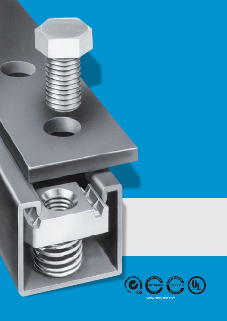
C-CHANNELCATALOGUE
www.ikkgroup.com
- About SFSP
- General Information
- Channels
- Toothed Channels
- Fittings
- Accessories
- Anchors
- Locations
INDEXC-Channel Catalogue
4
18
23
84
88
94
100
112
2
www.sfsp-ikk.com

3
ABOUTSFSP
4
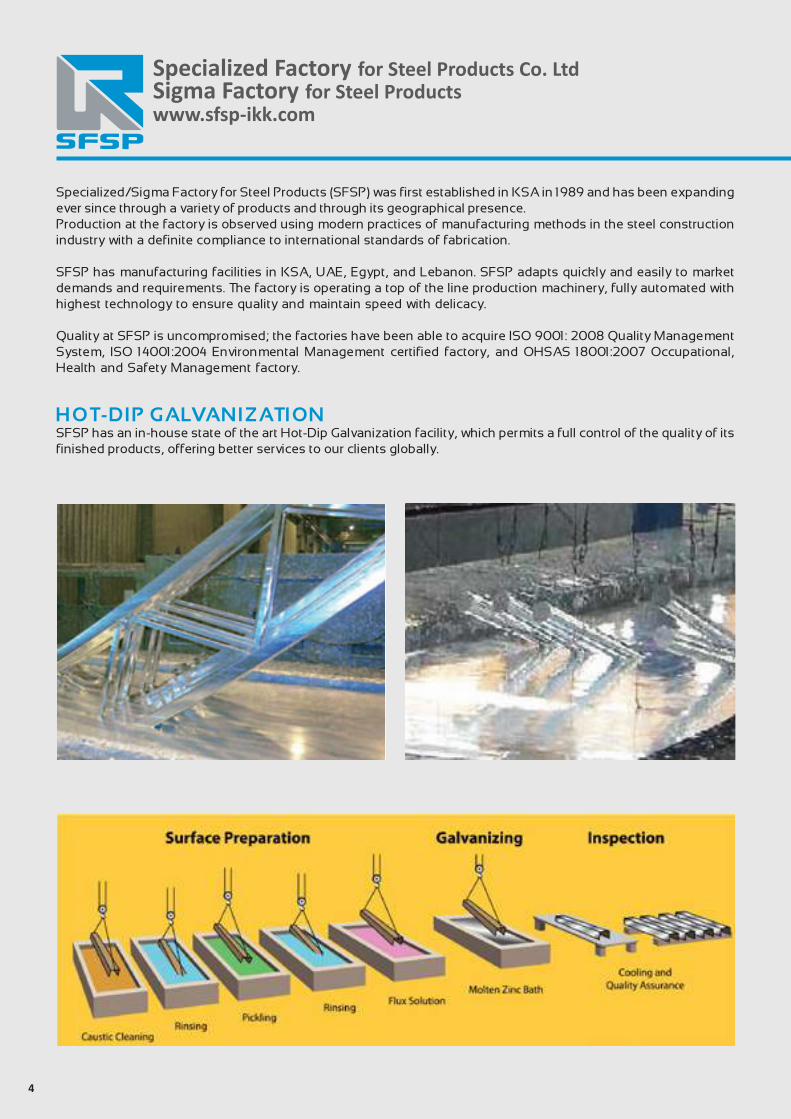
Specialized/Sigma Factory for Steel Products (SFSP) was first established in KSA in 1989 and has been expanding ever since through a variety of products and through its geographical presence.Production at the factory is observed using modern practices of manufacturing methods in the steel construction industry with a definite compliance to international standards of fabrication. SFSP has manufacturing facilities in KSA, UAE, Egypt, and Lebanon. SFSP adapts quickly and easily to market demands and requirements. The factory is operating a top of the line production machinery, fully automated with highest technology to ensure quality and maintain speed with delicacy.
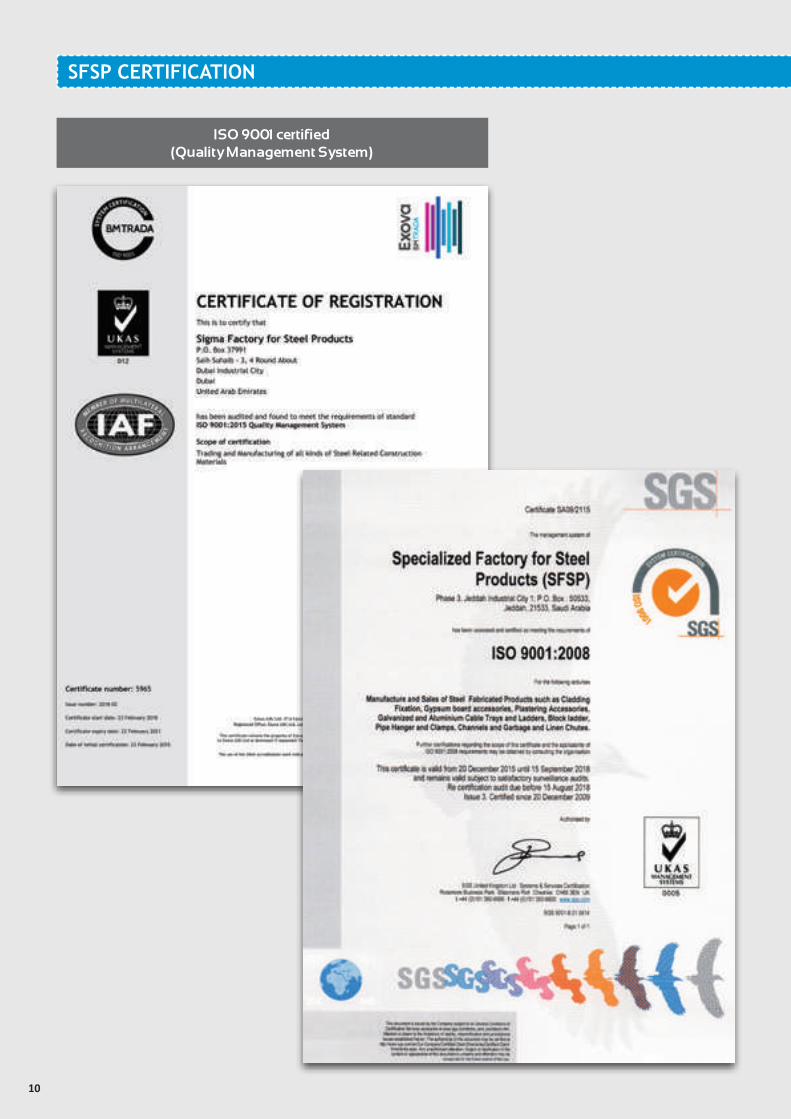
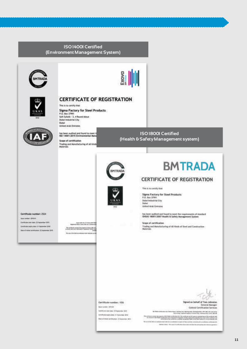
Quality at SFSP is uncompromised; the factories have been able to acquire ISO 9001: 2008 Quality Management System, ISO 14001:2004 Environmental Management certified factory, and OHSAS 18001:2007 Occupational, Health and Safety Management factory.
HOT-DIP GALVANIZATIONSFSP has an in-house state of the art Hot-Dip Galvanization facility, which permits a full control of the quality of its finished products, offering better services to our clients globally.
Specialized Factory for Steel Products Co. LtdSigma Factory for Steel Productswww.sfsp-ikk.com
5
Specialized Factory for Steel Products Co. Ltdwww.sfsp-ikk.com
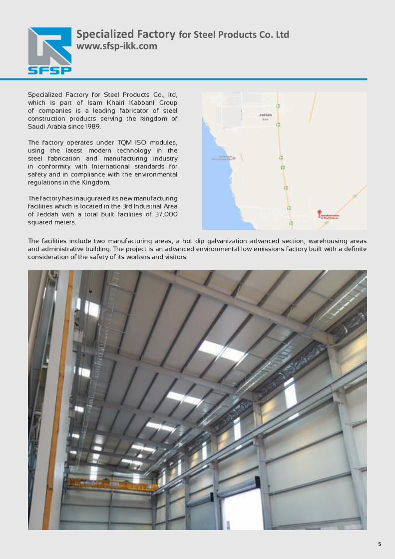
Specialized Factory for Steel Products Co., ltd, which is part of Isam Khairi Kabbani Group of companies is a leading fabricator of steel construction products serving the kingdom of Saudi Arabia since 1989.
The factory operates under TQM ISO modules, using the latest modern technology in the steel fabrication and manufacturing industry in conformity with International standards for safety and in compliance with the environmental regulations in the Kingdom.
The factory has inaugurated its new manufacturing facilities which is located in the 3rd Industrial Area of Jeddah with a total built facilities of 37,000 squared meters.
The facilities include two manufacturing areas, a hot dip galvanization advanced section, warehousing areas and administrative building. The project is an advanced environmental low emissions factory built with a definite consideration of the safety of its workers and visitors.
6
Specialized Factory for Steel Products Co. LtdSigma Factory for Steel Productswww.sfsp-ikk.com
A crucial factor in the job of a factory is to provide continuous technical services and consultations.That’s why SFSP has invested in a professional team of researchers and specialists.
SFSP has recruited brilliant graduates and experienced engineers having the appropriate knowhow on the on latest technology changes and development in the steel building materials industry.
The product range is developed and updated according to the relevant standards of fabrication across markets, whilst the business processes are evaluated to achieve maximum efficiency.
SFSP R&D Core Objectives- Carry out responsibilities effectively in a safe and healthy work environment.- Develop and implement research programs relevant to the products and solutions introduced and ensure that the
results are communicated clearly in-house and among the clients , concisely and accurately.
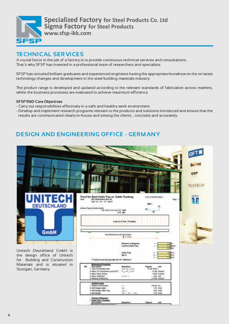
Unitech Deutshland GmbH is the design office of Unitech for Building and Construction Materials and is situated in Stuttgart, Germany.
DESIGN AND ENGINEERING OFFICE - GERMANY
TECHNICAL SERVICES
7
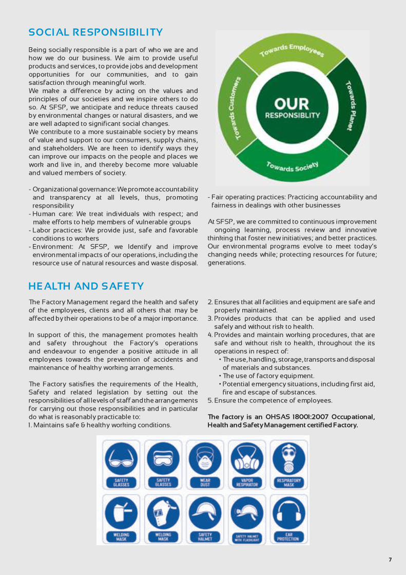
SOCIAL RESPONSIBILITY
Being socially responsible is a part of who we are and how we do our business. We aim to provide useful products and services, to provide jobs and development opportunities for our communities, and to gain satisfaction through meaningful work. We make a difference by acting on the values and principles of our societies and we inspire others to do so. At SFSP, we anticipate and reduce threats caused by environmental changes or natural disasters, and we are well adapted to significant social changes. We contribute to a more sustainable society by means of value and support to our consumers, supply chains, and stakeholders. We are keen to identify ways they can improve our impacts on the people and places we work and live in, and thereby become more valuable and valued members of society.
- Organizational governance: We promote accountability and transparency at all levels, thus, promoting responsibility
- Human care: We treat individuals with respect; and make efforts to help members of vulnerable groups
- Labor practices: We provide just, safe and favorable conditions to workers
- Environment: At SFSP, we Identify and improve environmental impacts of our operations, including the resource use of natural resources and waste disposal.
- Fair operating practices: Practicing accountability and fairness in dealings with other businesses
At SFSP, we are committed to continuous improvement – ongoing learning, process review and innovative thinking that foster new initiatives; and better practices. Our environmental programs evolve to meet today’s changing needs while; protecting resources for future; generations.
HEALTH AND SAFETY
The Factory Management regard the health and safety of the employees, clients and all others that may be affected by their operations to be of a major importance.
In support of this, the management promotes health and safety throughout the Factory’s operations and endeavour to engender a positive attitude in all employees towards the prevention of accidents and maintenance of healthy working arrangements.
The Factory satisfies the requirements of the Health, Safety and related legislation by setting out the responsibilities of all levels of staff and the arrangements for carrying out those responsibilities and in particular do what is reasonably practicable to:1. Maintains safe & healthy working conditions.
2. Ensures that all facilities and equipment are safe and properly maintained.
3. Provides products that can be applied and used safely and without risk to health.
4. Provides and maintain working procedures, that are safe and without risk to health, throughout the its operations in respect of:
• The use, handling, storage, transports and disposal of materials and substances.
• The use of factory equipment. • Potential emergency situations, including first aid,
fire and escape of substances.5. Ensure the competence of employees.
The factory is an OHSAS 18001:2007 Occupational, Health and Safety Management certified Factory.
8
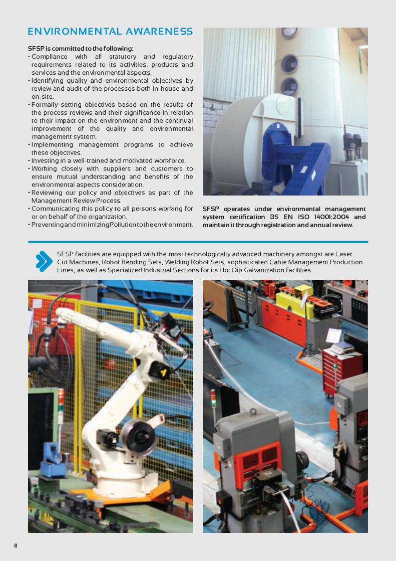
SFSP facilities are equipped with the most technologically advanced machinery amongst are Laser Cut Machines, Robot Bending Sets, Welding Robot Sets, sophisticated Cable Management Production Lines, as well as Specialized Industrial Sections for its Hot Dip Galvanization facilities.
ENVIRONMENTAL AWARENESS
SFSP is committed to the following:• Compliance with all statutory and regulatory
requirements related to its activities, products and services and the environmental aspects.
• Identifying quality and environmental objectives by review and audit of the processes both in-house and on-site.
• Formally setting objectives based on the results of the process reviews and their significance in relation to their impact on the environment and the continual improvement of the quality and environmental management system.
• Implementing management programs to achieve these objectives.
• Investing in a well-trained and motivated workforce.• Working closely with suppliers and customers to
ensure mutual understanding and benefits of the environmental aspects consideration.
• Reviewing our policy and objectives as part of the Management Review Process.
• Communicating this policy to all persons working for or on behalf of the organization.
• Preventing and minimizing Pollution to the environment.
SFSP operates under environmental management system certification BS EN ISO 14001:2004 and maintain it through registration and annual review.
9
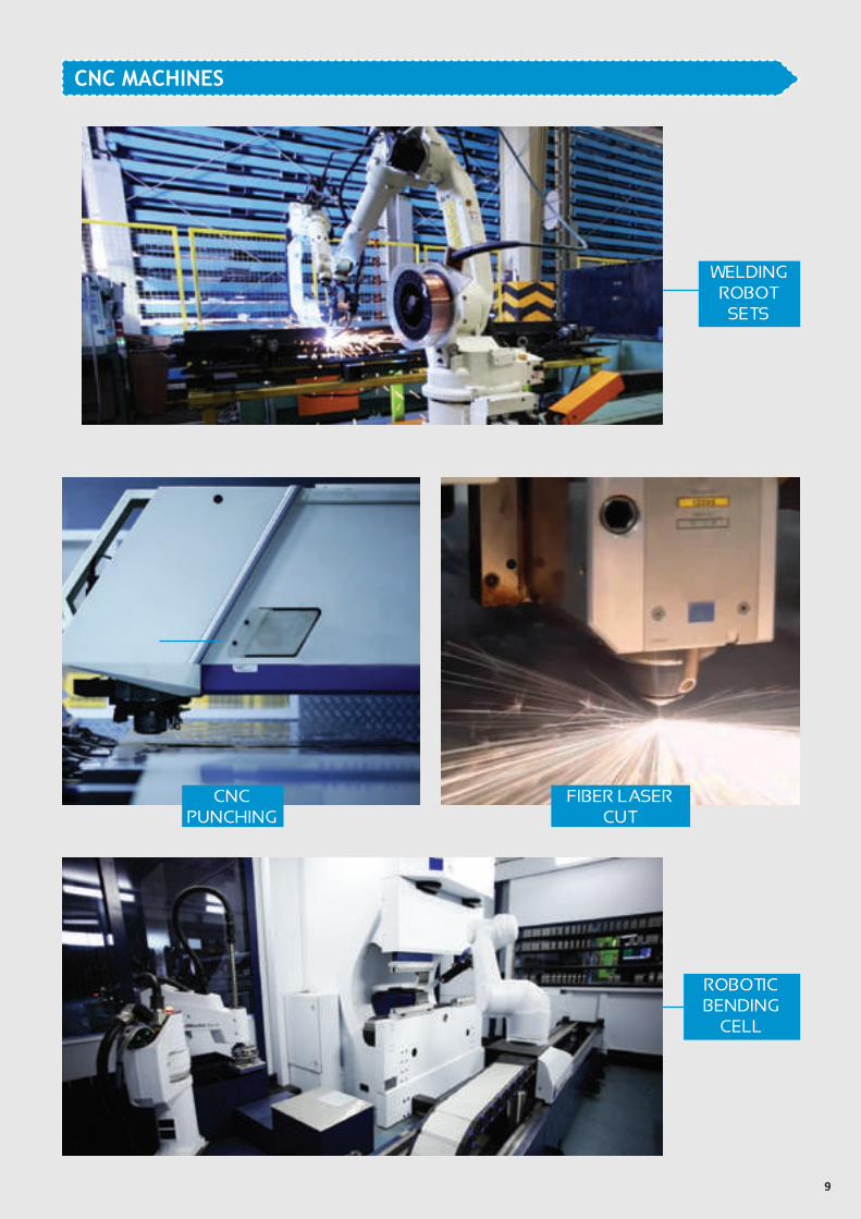
CNC MACHINES
WELDING ROBOT
SETS
CNC PUNCHING
FIBER LASER CUT
ROBOTIC BENDING
CELL
10
SFSP CERTIFICATION
ISO 9001 certified (Quality Management System)
11
ISO 14001 Certified(Environment Management System)
ISO 18001 Certified (Health & Safety Management system)
12
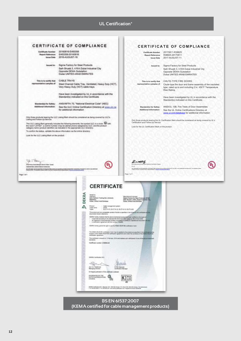
UL Certification*
BS EN 61537:2007(KEMA certified for cable management products)
C E R T I F I C A T E O F C O M P L I A N C E
Certificate Number 20170811-R38825 Report Reference R38825-20170811
Issue Date 2017-AUGUST-11
Bruce Mahrenholz, Director North American Certification Program UL LLC Any information and documentation involving UL Mark services are provided on behalf of UL LLC (UL) or any authorized licensee of UL. For questions, please contact a local UL Customer Service Representative at http://ul.com/aboutul/locations/
Page 1 of 1
Issued to: Sigma Factory for Steel Products Saih Shuaib 3, 4 R/A Dubai Industrial City Opposite DEWA Substation Dubai UNITED ARAB EMIRATES
This is to certify that representative samples of
CHUTE-TYPE FIRE DOORS Chute-type fire door and frame assembly of the insulated type, rated up to and including 2 hr, 450°F Temperature Rise Rating.
Have been investigated by UL in accordance with the Standard(s) indicated on this Certificate.
Standard(s) for Safety: ANSI/UL 10B, Fire Tests of Door Assemblies Additional Information: See the UL Online Certifications Directory at
www.ul.com/database for additional information
Only those products bearing the UL Certification Mark should be considered as being covered by UL's Certification and Follow-Up Service. Look for the UL Certification Mark on the product.
13
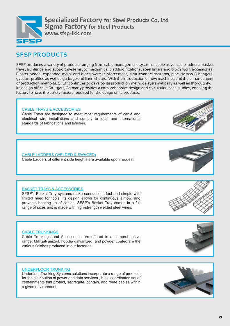
SFSP PRODUCTS
SFSP produces a variety of products ranging from cable management systems; cable trays, cable ladders, basket trays, trunkings and support systems, to mechanical cladding fixations, steel lintels and block work accessories, Plaster beads, expanded metal and block work reinforcement, strut channel systems, pipe clamps & hangers, gypsum profiles as well as garbage and linen chutes. With the introduction of new machines and the enhancement of production methods, SFSP continues to develop its production methods systematically as well as thoroughly. Its design office in Stuttgart, Germany provides a comprehensive design and calculation case studies, enabling the factory to have the safety factors required for the usage of its products.
Specialized Factory for Steel Products Co. LtdSigma Factory for Steel Productswww.sfsp-ikk.com
CABLE TRAYS & ACCESSORIESCable Trays are designed to meet most requirements of cable and electrical wire installations and comply to local and international standards of fabrications and finishes.
CABLE LADDERS (WELDED & SWAGED)Cable Ladders of different side heights are available upon request.
BASKET TRAYS & ACCESSORIESSFSP’s Basket Tray systems make connections fast and simple with limited need for tools. Its design allows for continuous airflow, and prevents heating up of cables. SFSP’s Basket Tray comes in a full range of sizes and is made with high-strength welded steel wires.
CABLE TRUNKINGSCable Trunkings and Accessories are offered in a comprehensive range. Mill galvanized, hot-dip galvanized, and powder coated are the various finishes produced in our factories.
UNDERFLOOR TRUNKINGUnderfloor Trunking Systems solutions incorporate a range of products for the distribution of power and data services , it is a coordinated set of containments that protect, segregate, contain, and route cables within a given environment.
14
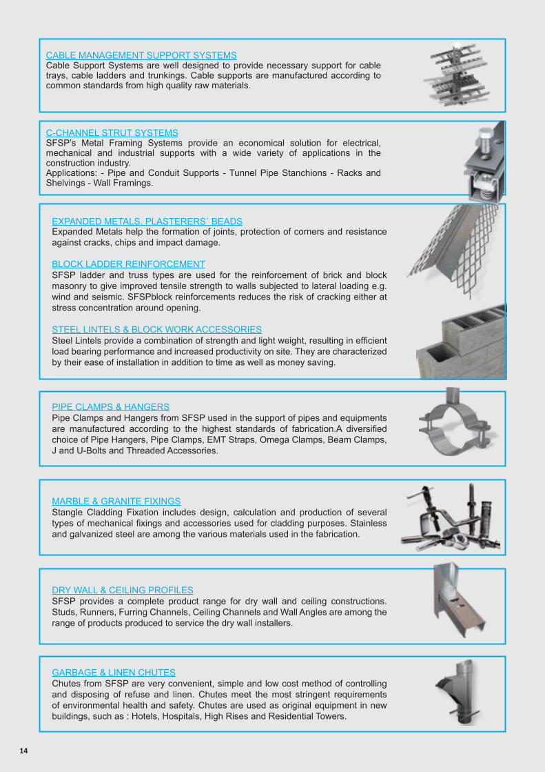
EXPANDED METALS, PLASTERERS` BEADSExpanded Metals help the formation of joints, protection of corners and resistance against cracks, chips and impact damage.
BLOCK LADDER REINFORCEMENTSFSP ladder and truss types are used for the reinforcement of brick and block masonry to give improved tensile strength to walls subjected to lateral loading e.g. wind and seismic. SFSPblock reinforcements reduces the risk of cracking either at stress concentration around opening.
STEEL LINTELS & BLOCK WORK ACCESSORIESSteel Lintels provide a combination of strength and light weight, resulting in efficient load bearing performance and increased productivity on site. They are characterized by their ease of installation in addition to time as well as money saving.
PIPE CLAMPS & HANGERSPipe Clamps and Hangers from SFSP used in the support of pipes and equipments are manufactured according to the highest standards of fabrication.A diversified choice of Pipe Hangers, Pipe Clamps, EMT Straps, Omega Clamps, Beam Clamps, J and U-Bolts and Threaded Accessories.
MARBLE & GRANITE FIXINGSStangle Cladding Fixation includes design, calculation and production of several types of mechanical fixings and accessories used for cladding purposes. Stainless and galvanized steel are among the various materials used in the fabrication.
DRY WALL & CEILING PROFILESSFSP provides a complete product range for dry wall and ceiling constructions. Studs, Runners, Furring Channels, Ceiling Channels and Wall Angles are among the range of products produced to service the dry wall installers.
GARBAGE & LINEN CHUTESChutes from SFSP are very convenient, simple and low cost method of controlling and disposing of refuse and linen. Chutes meet the most stringent requirements of environmental health and safety. Chutes are used as original equipment in new buildings, such as : Hotels, Hospitals, High Rises and Residential Towers.
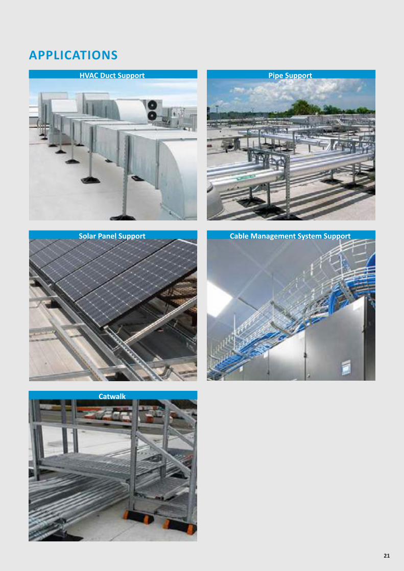
C-CHANNEL STRUT SYSTEMSSFSP’s Metal Framing Systems provide an economical solution for electrical, mechanical and industrial supports with a wide variety of applications in the construction industry.Applications: - Pipe and Conduit Supports - Tunnel Pipe Stanchions - Racks and Shelvings - Wall Framings.
CABLE MANAGEMENT SUPPORT SYSTEMSCable Support Systems are well designed to provide necessary support for cable trays, cable ladders and trunkings. Cable supports are manufactured according to common standards from high quality raw materials.
15
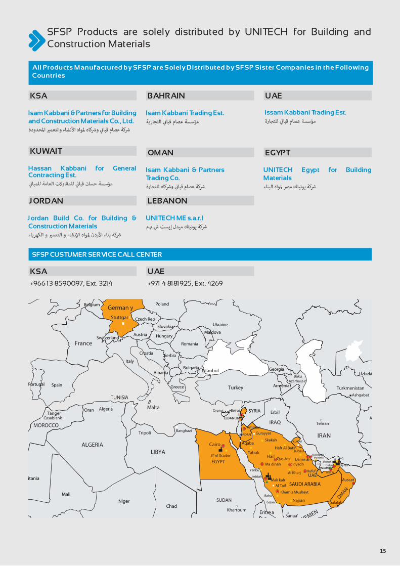
SFSP Products are solely distributed by UNITECH for Building and Construction Materials
Isam Kabbani & Partners for Building and Construction Materials Co., Ltd.
Jordan Build Co. for Building & Construction Materials –
UNITECH ME s.a.r.l –
Issam Kabbani Trading Est. –
+971 4 8181925, Ext. 4269+966 13 8590097, Ext. 3214
Isam Kabbani Trading Est.
KSA
Hassan Kabbani for General Contracting Est.
KUWAIT
UNITECH Egypt for Building Materials
EGYPT
JORDAN
Isam Kabbani & Partners Trading Co.
OMAN
LEBANON
BAHRAIN UAE
UAEKSA
All Products Manufactured by SFSP are Solely Distributed by SFSP Sister Companies in the Following Countries
SFSP CUSTUMER SERVICE CALL CENTER
Senegal
Kazakhstan
Spain
France
German yPoland
Greece
Albania
HungaryAustria
Slovakia
Czech RepUkraine
Maldova
Romania
Bulgaria
SerbiaCroatia
Italy
Turkey
Georgia
PortugalTurkmenistan
Afghanistan
Pakistan
Uzbekistan
Tajikistan
IRAN
Tehran
Ashgabat
Kabol
Skakah
Gurayyat
Mak kahAl Taif
BeirutCyprus
SAUDI ARABIA
SYRIA
EGYPT
LEBANON
JORDAN
IRAQ
UAE
BAHRAIN
Najran
Khamis Mushayt
Riyadh
Hail Qassim
Yanbu
Jeddah
Dammam Manama
JubailHafr Al Batin
Gizan
Baha
Ma dinah
Hufuf
Cairo
YEMEN
SUDANChad
Niger
Aqaba
Al Kharj
Amman
Ajman
6th of October
Jebel Ali
TabukLIBYAALGERIA
TUNISIA
Malta
MOROCCO
OMAN
KUWAIT
Tripoli Banghazi
AlgeriaOranTanger
Casablank a
Muscat
Sanaa’
Adan
Khartoum
Salalah
Erbi l
Baku
DubaiSharjah
U A Q
Nigeria
Cameroon
Ethiopia
Djipouti
Eritre a
Somalia
CentralAfrican
Republic
Mali
Burkina Faso
GhanaCote
d’lvoire
Guinea
Mauritania
Benin
Abuja
Stuttgar t
Norway
Birmingha m
Ireland
Sweden
Finland
Denmark
Netherlands
Switzerland
Belgium
Finland
Estonia
Latvia
Lithuania
Azerbaija nArmenia
Belarus
Istanbul
UK
16
IKKGroup of Companies
The IKK Group is a major business institution, serving most of the Arab World in the industrial, construction and trading fields, as well as in specialized maintenance and services.
Today, the IKK Group of Companies is a pioneer in waterproofing, weatherproofing, building material supplies, UPVC and CPVC and high density polyethylene pipes and fittings and several other products for the construction industry.
The Group is also represented in the sanitary products, steel production, kitchen manufacturing, telecommunications, food, decoration, re-insurance and real estate business domain.
Composed of 60 companies, the IKK Group operates through almost 200 divisions, branches and outlets; it is spread over 12 countries, covering all major cities in the region and employing around 13,000 employees.
Our vision is to maintain and improve our leading position as a contractor whose reputation is built on the ability to completely satisfy customers by providing high quality services. As specialists in their respective fields, our teams of professionals are dedicated to a standard of excellence for quality and performance, through continuous development, which will set standards in our industry.We are simply providing solutions for a future of success.
Our mission is to provide our part of the Arab World with local and reliable services in a variety of sectors and products.
To create employment to thousands of personnel and in-house training for hundreds of young Arab graduates in crucial sectors to the benefit of the IKK Group, the graduates themselves and their own communities.
To set a good example of our basic business philosophy: “Hire well, train well, pay well and treat well.”
UNITECH ISAM KABBANI & PARTNERS FOR BUILDING & CONSTRUCTION MATERIALS
Isam Kabbani & Partners for buildings & construction materials co. Ltd (UNITECH) which is part of the IKK group of companies is recognized and acknowledged for the quality and reliability of its products and services as well as for the commitment, professionalism and experience of its employees.
Isam Kabbani & partners for buildings & construction materials co. Ltd (UNITECH) core valuse are to offer value products and services to its clients, to work closely with them in a lasting business partnership that provides an outstanding performance.
A partnership based on trust, harmony, and a hard to beat services and solutions.
Our Factories have acquired, in addition to ISO 9001:2008 Quality Management System, the ISO 14001:2004 Environmental Management System.
Our care for the environment has been translated via Isam Kabbani &partners for buildings &construction materials co. Ltd (UNITECH)’s membership in the US Green Building Council as a Golden Member.
Our VisionUNITECH to be the Customer’s First Choice.
Our MissionWe have the conviction to be the leader in building & construction industry through:- Providing Excellence in Services with Passionate and
Educated Sales Force- Strengthen Culture through Unified Sense of Purpose- Innovative Product Range which is Customer Centric- Reputable and Quality Service Company- Attracting, Engaging and Retaining Talent
www.sfsp-ikk.com
GENERAL INFORMATION
18
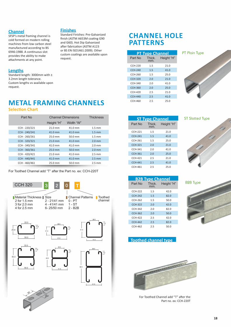
ChannelSFSP’s metal framing channel is cold formed on modern rolling machines from low carbon steel manufactured according to BS 6946:1988. A continuous slot provides the ability to make attachments at any point.
LengthsStandard length: 3000mm with ± 3.2mm length tolerance.Custom lengths vv available upon request.
Z
Z
YY
Z
Z
YY
Z
Z
YY
Z
Z
Y Y
21.0
7.0
41.0
21.0
41.0
22.0
42.0
7.0
41.0
22.0
41.0
7.0
41.0
41.0
41.0
22.0
82.0
7.0
41.0
22.0
50
30
13
Z
Z
YY
Z
Z
YY
Z
Z
YY
Z
Z
Y Y
21.0
7.0
41.0
21.0
41.0
22.0
42.0
7.0
41.0
22.0
41.0
7.0
41.0
41.0
41.0
22.0
82.0
7.0
41.0
22.0
50
30
13
Z
Z
YY
Z
Z
YY
Z
Z
YY
Z
Z
Y Y
21.0
7.0
41.0
21.0
41.0
22.0
42.0
7.0
41.0
22.0
41.0
7.0
41.0
41.0
41.0
22.0
82.0
7.0
41.0
22.0
50
30
13
Z
Z
YY
Z
Z
YY
Z
Z
YY
Z
Z
Y Y
21.0
7.0
41.0
21.0
41.0
22.0
42.0
7.0
41.0
22.0
41.0
7.0
41.0
41.0
41.0
22.0
82.0
7.0
41.0
22.0
50
30
13
Z
Z
YY
Z
Z
YY
Z
Z
YY
Z
Z
Y Y
21.0
7.0
41.0
21.0
41.0
22.0
42.0
7.0
41.0
22.0
41.0
7.0
41.0
41.0
41.0
22.0
82.0
7.0
41.0
22.0
50
30
13
CHANNEL HOLE PATTERNS
METAL FRAMING CHANNELSSelection Chart
PT Type Channel
ST Type Channel
PT Plain Type
ST Slotted Type
B2B TypeB2B Type Channel
Toothed channel type
For Toothed Channel add “T” after the Part no. ex: CCH-220T
For Toothed Channel add “T” after thePart no. ex: CCH-220T
CCH 320 3 2 0
Channel Patterns0 - PT 1 - ST2 - B2B
Toothed channel
Size2 - 21/41 mm 4 - 41/41 mm6- 25/50 mm
Material Thickness2 for 1.5 mm3 for 2.0 mm 4 for 2.5 mm
T
FinishesStandard Finishes: Pre-Galvanized finish (ASTM A653M coating G90 and G60). Hot Dip Galvanized after fabrication (ASTM A123 or BS EN ISO1461:2009). Other custom coatings are available upon request. Part No Thick.
mm.Height “H”
CCH-220 1.5 21.0
CCH-240 1.5 41.0
CCH-260 1.5 25.0
CCH-320 2.0 21.0
CCH-340 2.0 41.0
CCH-360 2.0 25.0
CCH-420 2.5 21.0
CCH-440 2.5 41.0
CCH-460 2.5 25.0
Part No Thick. mm.
Height “H”
CCH-221 1.5 21.0
CCH-241 1.5 41.0
CCH-261 1.5 25.0
CCH-321 2.0 21.0
CCH-341 2.0 41.0
CCH-361 2.0 25.0
CCH-421 2.5 21.0
CCH-441 2.5 41.0
CCH-461 2.5 25.0
Part No Thick. mm.
Height “H”
CCH-222 1.5 42.0
CCH-242 1.5 82.0
CCH-262 1.5 50.0
CCH-322 2.0 42.0
CCH-342 2.0 82.0
CCH-362 2.0 50.0
CCH-422 2.5 42.0
CCH-442 2.5 82.0
CCH-462 2.5 50.0
Part No Channel Dimensions Thickness
Height “H” Width “W”CCH - 220/221 21.0 mm 41.0 mm 1.5 mm
CCH - 240/241 41.0 mm 41.0 mm 1.5 mm
CCH - 260/261 25.0 mm 50.0 mm 1.5 mm
CCH - 320/321 21.0 mm 41.0 mm 2.0 mm
CCH - 340/341 41.0 mm 41.0 mm 2.0 mm
CCH - 360/361 25.0 mm 50.0 mm 2.0 mm
CCH - 420/421 21.0 mm 41.0 mm 2.5 mm
CCH - 440/441 41.0 mm 41.0 mm 2.5 mm
CCH - 460/461 25.0 mm 50.0 mm 2.5 mm
19
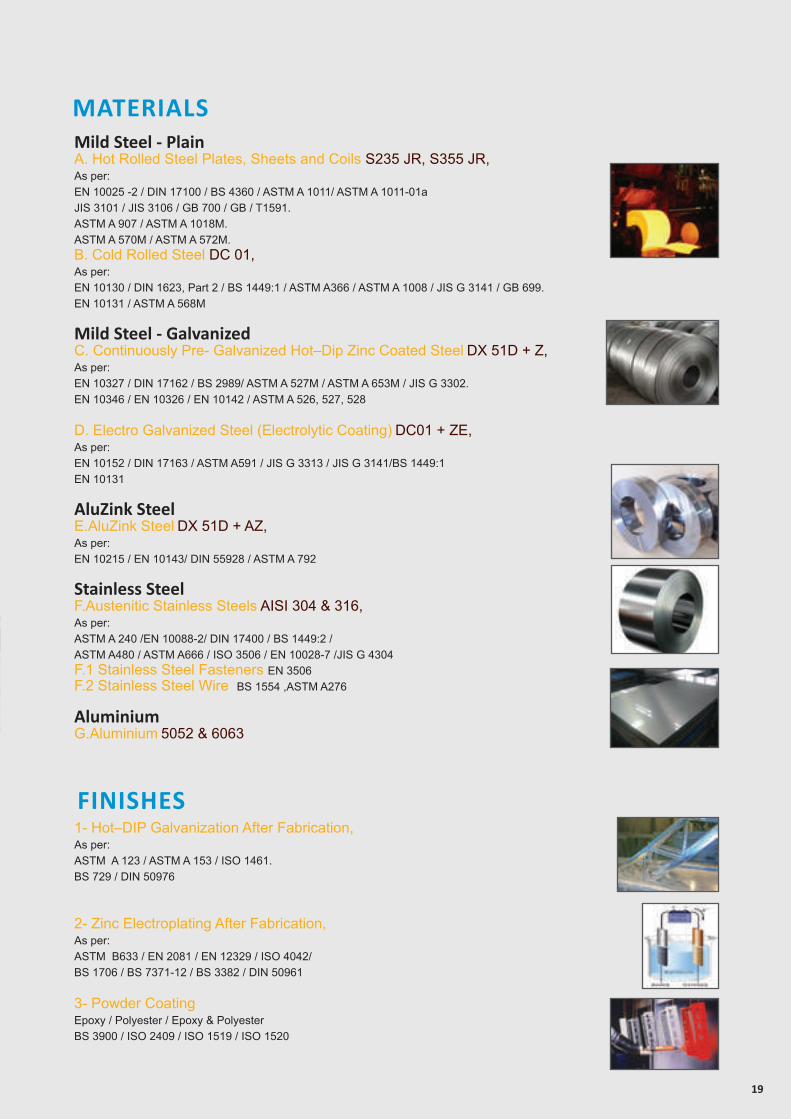
1- Hot–DIP Galvanization After Fabrication, As per:ASTM A 123 / ASTM A 153 / ISO 1461.BS 729 / DIN 50976
2- Zinc Electroplating After Fabrication,As per:ASTM B633 / EN 2081 / EN 12329 / ISO 4042/ BS 1706 / BS 7371-12 / BS 3382 / DIN 50961
3- Powder CoatingEpoxy / Polyester / Epoxy & PolyesterBS 3900 / ISO 2409 / ISO 1519 / ISO 1520
Mild Steel - PlainA. Hot Rolled Steel Plates, Sheets and Coils S235 JR, S355 JR,As per:EN 10025 -2 / DIN 17100 / BS 4360 / ASTM A 1011/ ASTM A 1011-01a JIS 3101 / JIS 3106 / GB 700 / GB / T1591.ASTM A 907 / ASTM A 1018M.ASTM A 570M / ASTM A 572M.B. Cold Rolled Steel DC 01,As per:EN 10130 / DIN 1623, Part 2 / BS 1449:1 / ASTM A366 / ASTM A 1008 / JIS G 3141 / GB 699.EN 10131 / ASTM A 568M
Mild Steel - Galvanized C. Continuously Pre- Galvanized Hot–Dip Zinc Coated Steel DX 51D + Z,As per: EN 10327 / DIN 17162 / BS 2989/ ASTM A 527M / ASTM A 653M / JIS G 3302.EN 10346 / EN 10326 / EN 10142 / ASTM A 526, 527, 528
D. Electro Galvanized Steel (Electrolytic Coating) DC01 + ZE,As per: EN 10152 / DIN 17163 / ASTM A591 / JIS G 3313 / JIS G 3141/BS 1449:1EN 10131
AluZink SteelE.AluZink Steel DX 51D + AZ,Aِs per: EN 10215 / EN 10143/ DIN 55928 / ASTM A 792
Stainless SteelF.Austenitic Stainless Steels AISI 304 & 316, As per: ASTM A 240 /EN 10088-2/ DIN 17400 / BS 1449:2 / ASTM A480 / ASTM A666 / ISO 3506 / EN 10028-7 /JIS G 4304F.1 Stainless Steel Fasteners EN 3506F.2 Stainless Steel Wire BS 1554 ,ASTM A276
AluminiumG.Aluminium 5052 & 6063
FINISHES
MATERIALS
20
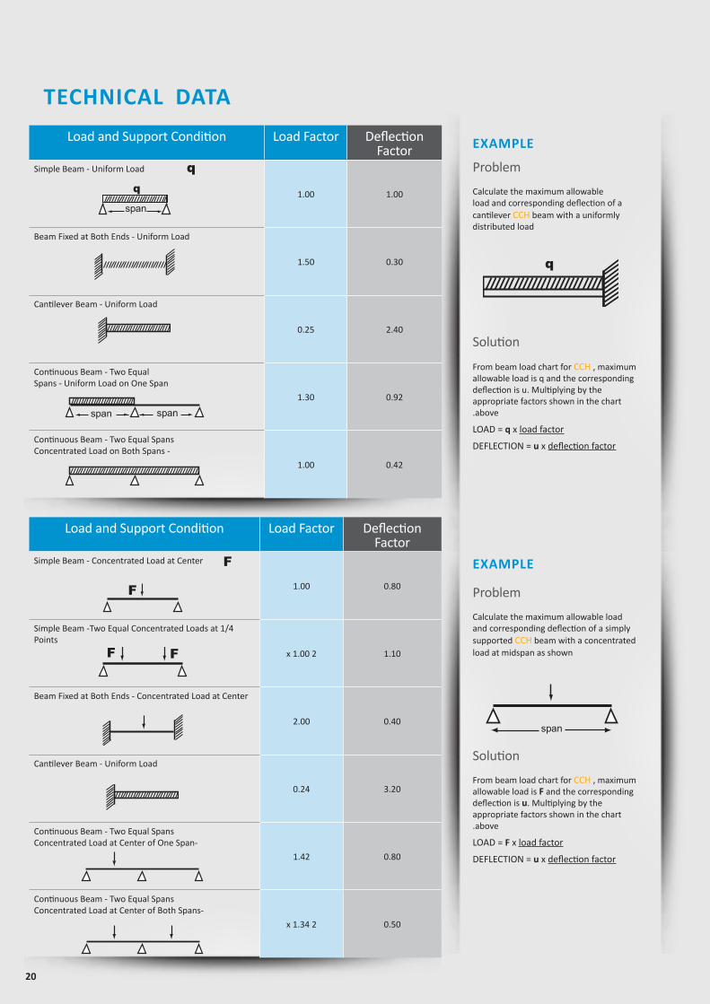
Load and Support Condition Load Factor Deflection Factor
Simple Beam - Concentrated Load at Center
1.00 0.80
Simple Beam -Two Equal Concentrated Loads at 1/4Points
x 1.00 2 1.10
Beam Fixed at Both Ends - Concentrated Load at Center
2.00 0.40
Cantilever Beam - Uniform Load
0.24 3.20
Continuous Beam - Two Equal SpansConcentrated Load at Center of One Span-
1.42 0.80
Continuous Beam - Two Equal SpansConcentrated Load at Center of Both Spans-
x 1.34 2 0.50
Load and Support Condition Load Factor DeflectionFactor
Simple Beam - Uniform Load
1.00 1.00
Beam Fixed at Both Ends - Uniform Load
1.50 0.30
Cantilever Beam - Uniform Load
0.25 2.40
Continuous Beam - Two EqualSpans - Uniform Load on One Span
1.30 0.92
Continuous Beam - Two Equal SpansConcentrated Load on Both Spans -
1.00 0.42
q
q
EXAMPLE
EXAMPLEF
TECHNICAL DATA
F F
F
span span
span
q
Problem
Calculate the maximum allowable load and corresponding deflection of a cantilever CCH beam with a uniformlydistributed load
Solution
From beam load chart for CCH , maximum allowable load is q and the corresponding deflection is u. Multiplying by the appropriate factors shown in the chart.above
LOAD = q x load factor
DEFLECTION = u x deflection factor
Problem
Calculate the maximum allowable load and corresponding deflection of a simply supported CCH beam with a concentratedload at midspan as shown
Solution
From beam load chart for CCH , maximum allowable load is F and the corresponding deflection is u. Multiplying by the appropriate factors shown in the chart.above
LOAD = F x load factor
DEFLECTION = u x deflection factor
span
21
APPLICATIONSHVAC Duct Support
Solar Panel Support
Catwalk
Pipe Support
Cable Management System Support
www.sfsp-ikk.com
CHANNELS

23
Load table for single beam with uniform (characteristic) Live-LoadThis associated data are considered for perforated and non-perforated c-channel types according to DIN 18.800
* Given loads are always “allowable characteristic live load”
Chosen Material:Allowable Bending Stress 21,82 kN/cm²Allowable Shear Stress 12,60 kN/cm²Modulus of Elasticity 21.000 kN/cm²
40B = S 235 JRG2
C-Channel:Area of Shear (Az)
1,67 cm
Moment of Inertia (Iy)
5,87 cm
Moment of Inertia (Iz
y
z
)
8,76 cm
min. Section Modulus (Sy)
2,72 cm
Warping Constant (Iw)
171,52 cm
Torsional Constant (IT)
0,07 cm
Plastic Moment cap. (Mpl,y)
0,82 kNm
Self weight (G)
2,32 kg/m
C 41x41x2,52
4
4
3
6
4
cmcmcmcmcmcmkNmkg/m
2
4
4
3
6
4
C-Channel:Cross Section Area (A) cm2
Moment of Inertia (I ) cm4
4Moment of Inertia (I ) cmSelf Weight (G) kg/m
^
Allowable Load
Span
F
Chosen Material:Allowable Bending Stress 21,82 kN/cm²Allowable Shear Stress 12,60 kN/cm²Modulus of Elasticity 21.000 kN/cm²
40B = S 235 JRG2
C-Channel:Area of Shear (Az)
1,67 cm
Moment of Inertia (Iy)
5,87 cm
Moment of Inertia (Iz
y
z
)
8,76 cm
min. Section Modulus (Sy)
2,72 cm
Warping Constant (Iw)
171,52 cm
Torsional Constant (IT)
0,07 cm
Plastic Moment cap. (Mpl,y)
0,82 kNm
Self weight (G)
2,32 kg/m
C 41x41x2,52
4
4
3
6
4
cmcmcmcmcmcmkNmkg/m
2
4
4
3
6
4
C-Channel:Cross Section Area (A) cm2
Moment of Inertia (I ) cm4
4Moment of Inertia (I ) cmSelf Weight (G) kg/m
^
Allowable Uniform Load
Span
q
Z
Z
YY
Z
Z
YY
Z
Z
YY
Z
Z
Y Y
21.0
7.0
41.0
21.0
41.0
22.0
42.0
7.0
41.0
22.0
41.0
7.0
41.0
41.0
41.0
22.0
82.0
7.0
41.0
22.0
50
30
13
C-Channel: 41 x 21 x 1.5Area of Shear (Az) 0.42 cm2
Moment of Inertia (Iy) 0.70 cm4
Moment of Inertia (Iz) 3.34 cm4
min. Section Modulus (Sy) 0.60 cm3
Warping Constant (Iw) 17.49 cm6
Torsional Constant (IT) 0.01 cm4
Plastic Moment cap. (Mpl,y) 0.19 kNm
Self weight (G) 0.97 kg/m
Chosen Material: 40 B = S 235 JRG2Allowable Bending Stress 21,82 kN/cm2
Allowable Shear Stress 12,60 kN/cm2
Modulus of Elasticity 21.000 kN/cm2
Uniform Load* @
Span (L) Allowable Load* Deflection L / 360 L / 180
[cm] q [kN/m] F [kN] U [mm] [L /X] q [kN/m] q [kN/m]
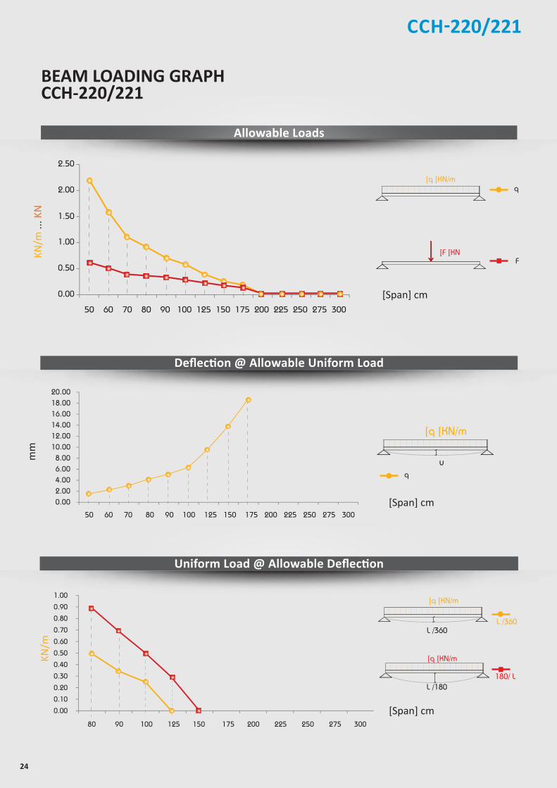
50 2.20 0.60 1.52 330 2.00 2.20
60 1.60 0.50 2.30 260 1.20 1.60
70 1.10 0.39 2.92 240 0.73 1.14
80 0.90 0.36 4.08 200 0.49 0.87
90 0.69 0.31 5.01 180 0.34 0.69
100 0.56 0.28 6.20 160 0.25 0.50
125 0.36 0.23 9.73 130 x 0.26
150 0.25 0.19 14.01 110 x x
175 0.18 0.16 18.69 90 x x
200 x x x x x x
225 x x x x x x
250 x x x x x x
275 x x x x x x
300 x x x x x x
Thickness : 1.5 mmStandard Length : 3.00 m Finishes : Pre-Galvanized, Hot-Dip Galvanized.
C C H - 2 2 1
Beam Load Data
CCH-220/221
24
BEAM LOADING GRAPH CCH-220/221
2.00
1.50
2.50
0.00
0.50
1.00
50 60 70 80 90 100 125 150 175 200 225 250 275 300
12.00 14.00 16.00 18.00 20.00
0.00 2.00 4.00 6.00 8.00
10.00
50 60 70 80 90 100 125 150 175 200 225 250 275 300
0.60 0.70 0.80 0.90 1.00
0.00 0.10 0.20 0.30 0.40 0.50
80 90 100 125 150 175 200 225 250 275 300
Allowable Loads
Deflection @ Allowable Uniform Load
Uniform Load @ Allowable Deflection
[Span] cm
[Span] cm
Chosen Material:Allowable Bending Stress 21,82 kN/cm²Allowable Shear Stress 12,60 kN/cm²Modulus of Elasticity 21.000 kN/cm²
40B = S 235 JRG2
C-Channel:Area of Shear (Az)
1,67 cm
Moment of Inertia (Iy)
5,87 cm
Moment of Inertia (Iz
y
z
)
8,76 cm
min. Section Modulus (Sy)
2,72 cm
Warping Constant (Iw)
171,52 cm
Torsional Constant (IT)
0,07 cm
Plastic Moment cap. (Mpl,y)
0,82 kNm
Self weight (G)
2,32 kg/m
C 41x41x2,52
4
4
3
6
4
cmcmcmcmcmcmkNmkg/m
2
4
4
3
6
4
C-Channel:Cross Section Area (A) cm2
Moment of Inertia (I ) cm4
4Moment of Inertia (I ) cmSelf Weight (G) kg/m
^
F
]q ]KN/m
]F ]KN
q
mm
KN/m
[Span] cm
180/ L
Chosen Material:Allowable Bending Stress 21,82 kN/cm²Allowable Shear Stress 12,60 kN/cm²Modulus of Elasticity 21.000 kN/cm²
40B = S 235 JRG2
C-Channel:Area of Shear (Az)
1,67 cm
Moment of Inertia (Iy)
5,87 cm
Moment of Inertia (Iz
y
z
)
8,76 cm
min. Section Modulus (Sy)
2,72 cm
Warping Constant (Iw)
171,52 cm
Torsional Constant (IT)
0,07 cm
Plastic Moment cap. (Mpl,y)
0,82 kNm
Self weight (G)
2,32 kg/m
C 41x41x2,52
4
4
3
6
4
cmcmcmcmcmcmkNmkg/m
2
4
4
3
6
4
C-Channel:Cross Section Area (A) cm2
Moment of Inertia (I ) cm4
4Moment of Inertia (I ) cmSelf Weight (G) kg/m
^
L /360
Chosen Material:Allowable Bending Stress 21,82 kN/cm²Allowable Shear Stress 12,60 kN/cm²Modulus of Elasticity 21.000 kN/cm²
40B = S 235 JRG2
C-Channel:Area of Shear (Az)
1,67 cm
Moment of Inertia (Iy)
5,87 cm
Moment of Inertia (Iz
y
z
)
8,76 cm
min. Section Modulus (Sy)
2,72 cm
Warping Constant (Iw)
171,52 cm
Torsional Constant (IT)
0,07 cm
Plastic Moment cap. (Mpl,y)
0,82 kNm
Self weight (G)
2,32 kg/m
C 41x41x2,52
4
4
3
6
4
cmcmcmcmcmcmkNmkg/m
2
4
4
3
6
4
C-Channel:Cross Section Area (A) cm2
Moment of Inertia (I ) cm4
4Moment of Inertia (I ) cmSelf Weight (G) kg/m
^
L /180
]q ]KN/m
L /360
]q ]KN/m
KN/m
... K
N
Chosen Material:Allowable Bending Stress 21,82 kN/cm²Allowable Shear Stress 12,60 kN/cm²Modulus of Elasticity 21.000 kN/cm²
40B = S 235 JRG2
C-Channel:Area of Shear (Az)
1,67 cm
Moment of Inertia (Iy)
5,87 cm
Moment of Inertia (Iz
y
z
)
8,76 cm
min. Section Modulus (Sy)
2,72 cm
Warping Constant (Iw)
171,52 cm
Torsional Constant (IT)
0,07 cm
Plastic Moment cap. (Mpl,y)
0,82 kNm
Self weight (G)
2,32 kg/m
C 41x41x2,52
4
4
3
6
4
cmcmcmcmcmcmkNmkg/m
2
4
4
3
6
4
C-Channel:Cross Section Area (A) cm2
Moment of Inertia (I ) cm4
4Moment of Inertia (I ) cmSelf Weight (G) kg/m
^
u
]q ]KN/m
q
CCH-220/221
25
Load table for single beam with uniform (characteristic) Live-LoadThis associated data are considered for perforated and non-perforated c-channel types according to DIN 18.800
** Given loads are always “allowable characteristic live load”
6.00
5.00
7.00
8.00
9.00
0.00
1.00
2.00
3.00
4.00
50 60 70 80 90 100 125 150 175 200 225 250 275 300
KN
[Length]cm
CCH-220/221Z
Z
YY
Z
Z
YY
Z
Z
YY
Z
Z
Y Y
21.0
7.0
41.0
21.0
41.0
22.0
42.0
7.0
41.0
22.0
41.0
7.0
41.0
41.0
41.0
22.0
82.0
7.0
41.0
22.0
50
30
13
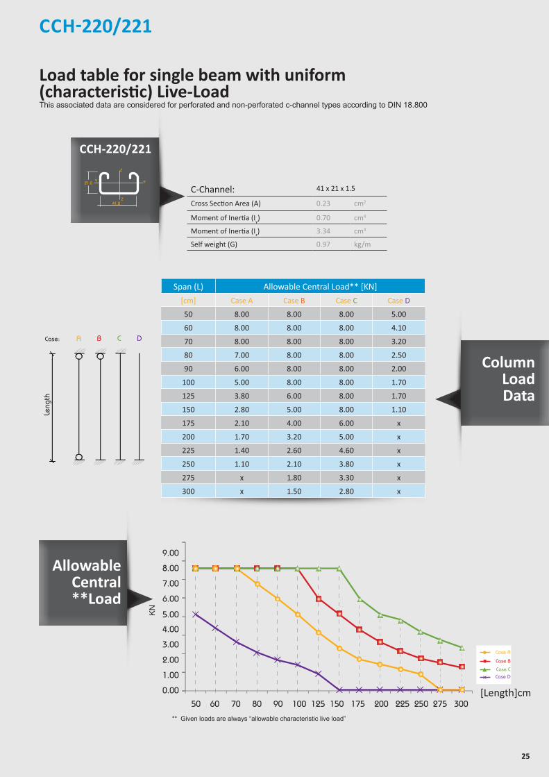
C-Channel: 41 x 21 x 1.5
Cross Section Area (A) 0.23 cm2
Moment of Inertia (Iy) 0.70 cm4
Moment of Inertia (Iz) 3.34 cm4
Self weight (G) 0.97 kg/mallowable uniform Load
ACase:
Length
B C D
Leng
th
Span (L) Allowable Central Load** [KN]
[cm] Case A Case B Case C Case D
50 8.00 8.00 8.00 5.00
60 8.00 8.00 8.00 4.10
70 8.00 8.00 8.00 3.20
80 7.00 8.00 8.00 2.50
90 6.00 8.00 8.00 2.00
100 5.00 8.00 8.00 1.70
125 3.80 6.00 8.00 1.70
150 2.80 5.00 8.00 1.10
175 2.10 4.00 6.00 x
200 1.70 3.20 5.00 x
225 1.40 2.60 4.60 x
250 1.10 2.10 3.80 x
275 x 1.80 3.30 x
300 x 1.50 2.80 x
Case A
Case B
Case CCase D
Allowable Central**Load
Column LoadData
CCH-220/221
26
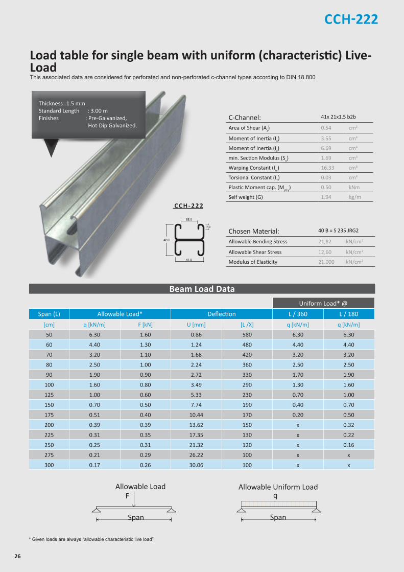
CCH-222
C-Channel: 41x 21x1.5 b2b
Area of Shear (Az) 0.54 cm2
Moment of Inertia (Iy) 3.55 cm4
Moment of Inertia (Iz) 6.69 cm4
min. Section Modulus (Sy) 1.69 cm3
Warping Constant (Iw) 16.33 cm6
Torsional Constant (IT) 0.03 cm4
Plastic Moment cap. (Mpl,y) 0.50 kNm
Self weight (G) 1.94 kg/m
Chosen Material: 40 B = S 235 JRG2
Allowable Bending Stress 21,82 kN/cm2
Allowable Shear Stress 12,60 kN/cm2
Modulus of Elasticity 21.000 kN/cm2
Z
Z
YY
Z
Z
YY
Z
Z
YY
Z
Z
Y Y
21.0
7.0
41.0
21.0
41.0
22.0
42.0
7.0
41.0
22.0
41.0
7.0
41.0
41.0
41.0
22.0
82.0
7.0
41.0
22.0
50
30
13
C C H - 2 2 2
* Given loads are always “allowable characteristic live load”
Beam Load Data
Chosen Material:Allowable Bending Stress 21,82 kN/cm²Allowable Shear Stress 12,60 kN/cm²Modulus of Elasticity 21.000 kN/cm²
40B = S 235 JRG2
C-Channel:Area of Shear (Az)
1,67 cm
Moment of Inertia (Iy)
5,87 cm
Moment of Inertia (Iz
y
z
)
8,76 cm
min. Section Modulus (Sy)
2,72 cm
Warping Constant (Iw)
171,52 cm
Torsional Constant (IT)
0,07 cm
Plastic Moment cap. (Mpl,y)
0,82 kNm
Self weight (G)
2,32 kg/m
C 41x41x2,52
4
4
3
6
4
cmcmcmcmcmcmkNmkg/m
2
4
4
3
6
4
C-Channel:Cross Section Area (A) cm2
Moment of Inertia (I ) cm4
4Moment of Inertia (I ) cmSelf Weight (G) kg/m
^
Allowable Load
Span
F
Chosen Material:Allowable Bending Stress 21,82 kN/cm²Allowable Shear Stress 12,60 kN/cm²Modulus of Elasticity 21.000 kN/cm²
40B = S 235 JRG2
C-Channel:Area of Shear (Az)
1,67 cm
Moment of Inertia (Iy)
5,87 cm
Moment of Inertia (Iz
y
z
)
8,76 cm
min. Section Modulus (Sy)
2,72 cm
Warping Constant (Iw)
171,52 cm
Torsional Constant (IT)
0,07 cm
Plastic Moment cap. (Mpl,y)
0,82 kNm
Self weight (G)
2,32 kg/m
C 41x41x2,52
4
4
3
6
4
cmcmcmcmcmcmkNmkg/m
2
4
4
3
6
4
C-Channel:Cross Section Area (A) cm2
Moment of Inertia (I ) cm4
4Moment of Inertia (I ) cmSelf Weight (G) kg/m
^
Allowable Uniform Load
Span
q
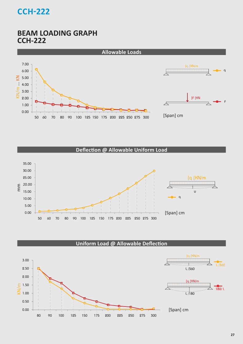
Thickness : 1.5 mmStandard Length : 3.00 m Finishes : Pre-Galvanized, Hot-Dip Galvanized.
Uniform Load* @
Span (L) Allowable Load* Deflection L / 360 L / 180
[cm] q [kN/m] F [kN] U [mm] [L /X] q [kN/m] q [kN/m]
50 6.30 1.60 0.86 580 6.30 6.30
60 4.40 1.30 1.24 480 4.40 4.40
70 3.20 1.10 1.68 420 3.20 3.20
80 2.50 1.00 2.24 360 2.50 2.50
90 1.90 0.90 2.72 330 1.70 1.90
100 1.60 0.80 3.49 290 1.30 1.60
125 1.00 0.60 5.33 230 0.70 1.00
150 0.70 0.50 7.74 190 0.40 0.70
175 0.51 0.40 10.44 170 0.20 0.50
200 0.39 0.39 13.62 150 x 0.32
225 0.31 0.35 17.35 130 x 0.22
250 0.25 0.31 21.32 120 x 0.16
275 0.21 0.29 26.22 100 x x
300 0.17 0.26 30.06 100 x x
Load table for single beam with uniform (characteristic) Live-LoadThis associated data are considered for perforated and non-perforated c-channel types according to DIN 18.800
27
CCH-222
25.00
20.00
30.00
35.00
0.00
5.00
10.00
15.00
50 60 70 80 90 100 125 150 175 200 225 250 275 300
[Span] cm
mm
[Span] cm
[Span] cm
5.00
6.00
7.00
0.00
1.00
2.00
3.00
4.00
50 60 70 80 90 100 125 150 175 200 225 250 275 300
KN/m
... K
N
2.00
2.50
3.00
0.00
0.50
1.00
1.50
80 90 100 125 150 175 200 225 250 275 300
KN/m
BEAM LOADING GRAPH CCH-222
Allowable Loads
Deflection @ Allowable Uniform Load
Uniform Load @ Allowable Deflection
Chosen Material:Allowable Bending Stress 21,82 kN/cm²Allowable Shear Stress 12,60 kN/cm²Modulus of Elasticity 21.000 kN/cm²
40B = S 235 JRG2
C-Channel:Area of Shear (Az)
1,67 cm
Moment of Inertia (Iy)
5,87 cm
Moment of Inertia (Iz
y
z
)
8,76 cm
min. Section Modulus (Sy)
2,72 cm
Warping Constant (Iw)
171,52 cm
Torsional Constant (IT)
0,07 cm
Plastic Moment cap. (Mpl,y)
0,82 kNm
Self weight (G)
2,32 kg/m
C 41x41x2,52
4
4
3
6
4
cmcmcmcmcmcmkNmkg/m
2
4
4
3
6
4
C-Channel:Cross Section Area (A) cm2
Moment of Inertia (I ) cm4
4Moment of Inertia (I ) cmSelf Weight (G) kg/m
^
F
]q ]KN/m
]F ]KN
q
180/ L
Chosen Material:Allowable Bending Stress 21,82 kN/cm²Allowable Shear Stress 12,60 kN/cm²Modulus of Elasticity 21.000 kN/cm²
40B = S 235 JRG2
C-Channel:Area of Shear (Az)
1,67 cm
Moment of Inertia (Iy)
5,87 cm
Moment of Inertia (Iz
y
z
)
8,76 cm
min. Section Modulus (Sy)
2,72 cm
Warping Constant (Iw)
171,52 cm
Torsional Constant (IT)
0,07 cm
Plastic Moment cap. (Mpl,y)
0,82 kNm
Self weight (G)
2,32 kg/m
C 41x41x2,52
4
4
3
6
4
cmcmcmcmcmcmkNmkg/m
2
4
4
3
6
4
C-Channel:Cross Section Area (A) cm2
Moment of Inertia (I ) cm4
4Moment of Inertia (I ) cmSelf Weight (G) kg/m
^
L /360
Chosen Material:Allowable Bending Stress 21,82 kN/cm²Allowable Shear Stress 12,60 kN/cm²Modulus of Elasticity 21.000 kN/cm²
40B = S 235 JRG2
C-Channel:Area of Shear (Az)
1,67 cm
Moment of Inertia (Iy)
5,87 cm
Moment of Inertia (Iz
y
z
)
8,76 cm
min. Section Modulus (Sy)
2,72 cm
Warping Constant (Iw)
171,52 cm
Torsional Constant (IT)
0,07 cm
Plastic Moment cap. (Mpl,y)
0,82 kNm
Self weight (G)
2,32 kg/m
C 41x41x2,52
4
4
3
6
4
cmcmcmcmcmcmkNmkg/m
2
4
4
3
6
4
C-Channel:Cross Section Area (A) cm2
Moment of Inertia (I ) cm4
4Moment of Inertia (I ) cmSelf Weight (G) kg/m
^
L /180
]q ]KN/m
L /360
]q ]KN/m
Chosen Material:Allowable Bending Stress 21,82 kN/cm²Allowable Shear Stress 12,60 kN/cm²Modulus of Elasticity 21.000 kN/cm²
40B = S 235 JRG2
C-Channel:Area of Shear (Az)
1,67 cm
Moment of Inertia (Iy)
5,87 cm
Moment of Inertia (Iz
y
z
)
8,76 cm
min. Section Modulus (Sy)
2,72 cm
Warping Constant (Iw)
171,52 cm
Torsional Constant (IT)
0,07 cm
Plastic Moment cap. (Mpl,y)
0,82 kNm
Self weight (G)
2,32 kg/m
C 41x41x2,52
4
4
3
6
4
cmcmcmcmcmcmkNmkg/m
2
4
4
3
6
4
C-Channel:Cross Section Area (A) cm2
Moment of Inertia (I ) cm4
4Moment of Inertia (I ) cmSelf Weight (G) kg/m
^
u
]q ]KN/m
q
28
CCH-222
CCH-222
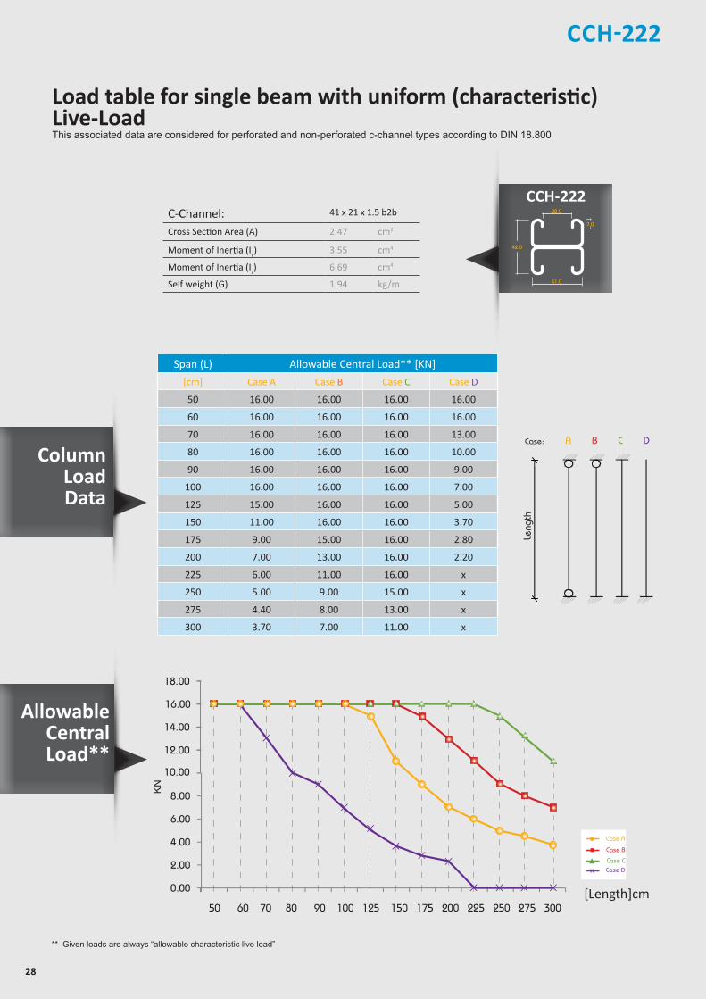
** Given loads are always “allowable characteristic live load”
allowable uniform Load
ACase:
Length
B C D
Leng
th
C-Channel: 41 x 21 x 1.5 b2b
Cross Section Area (A) 2.47 cm2
Moment of Inertia (Iy) 3.55 cm4
Moment of Inertia (Iz) 6.69 cm4
Self weight (G) 1.94 kg/m
Span (L) Allowable Central Load** [KN]
[cm] Case A Case B Case C Case D
50 16.00 16.00 16.00 16.00
60 16.00 16.00 16.00 16.00
70 16.00 16.00 16.00 13.00
80 16.00 16.00 16.00 10.00
90 16.00 16.00 16.00 9.00
100 16.00 16.00 16.00 7.00
125 15.00 16.00 16.00 5.00
150 11.00 16.00 16.00 3.70
175 9.00 15.00 16.00 2.80
200 7.00 13.00 16.00 2.20
225 6.00 11.00 16.00 x
250 5.00 9.00 15.00 x
275 4.40 8.00 13.00 x
300 3.70 7.00 11.00 x
12.00
10.00
14.00
16.00
18.00
0.00
2.00
4.00
6.00
8.00
50 60 70 80 90 100 125 150 175 200 225 250 275 300
KN
[Length]cm
Case A
Case B
Case CCase D
Allowable Central Load**
Column Load Data
Z
Z
YY
Z
Z
YY
Z
Z
YY
Z
Z
Y Y
21.0
7.0
41.0
21.0
41.0
22.0
42.0
7.0
41.0
22.0
41.0
7.0
41.0
41.0
41.0
22.0
82.0
7.0
41.0
22.0
50
30
13
Load table for single beam with uniform (characteristic) Live-LoadThis associated data are considered for perforated and non-perforated c-channel types according to DIN 18.800

29
CCH-240/241
C-Channel: 41x41x1.5
Area of Shear (Az) 1.02 cm2
Moment of Inertia (Iy) 3.87 cm4
Moment of Inertia (Iz) 5.68 cm4
min. Section Modulus (Sy) 1.76 cm3
Warping Constant (Iw) 114.17 cm6
Torsional Constant (IT) 0.02 cm4
Plastic Moment cap. (Mpl,y) 0.52 kNm
Self weight (G) 1.44 kg/m
Z
Z
YY
Z
Z
YY
Z
Z
YY
Z
Z
Y Y
21.0
7.0
41.0
21.0
41.0
22.0
42.0
7.0
41.0
22.0
41.0
7.0
41.0
41.0
41.0
22.0
82.0
7.0
41.0
22.0
50
30
13
* Given loads are always “allowable characteristic live load”
Beam Load Data
Chosen Material: 40 B = S 235 JRG2
Allowable Bending Stress 21,82 kN/cm2
Allowable Shear Stress 12,60 kN/cm2
Modulus of Elasticity 21.000 kN/cm2
Chosen Material:Allowable Bending Stress 21,82 kN/cm²Allowable Shear Stress 12,60 kN/cm²Modulus of Elasticity 21.000 kN/cm²
40B = S 235 JRG2
C-Channel:Area of Shear (Az)
1,67 cm
Moment of Inertia (Iy)
5,87 cm
Moment of Inertia (Iz
y
z
)
8,76 cm
min. Section Modulus (Sy)
2,72 cm
Warping Constant (Iw)
171,52 cm
Torsional Constant (IT)
0,07 cm
Plastic Moment cap. (Mpl,y)
0,82 kNm
Self weight (G)
2,32 kg/m
C 41x41x2,52
4
4
3
6
4
cmcmcmcmcmcmkNmkg/m
2
4
4
3
6
4
C-Channel:Cross Section Area (A) cm2
Moment of Inertia (I ) cm4
4Moment of Inertia (I ) cmSelf Weight (G) kg/m
^
Allowable Load
Span
F
Chosen Material:Allowable Bending Stress 21,82 kN/cm²Allowable Shear Stress 12,60 kN/cm²Modulus of Elasticity 21.000 kN/cm²
40B = S 235 JRG2
C-Channel:Area of Shear (Az)
1,67 cm
Moment of Inertia (Iy)
5,87 cm
Moment of Inertia (Iz
y
z
)
8,76 cm
min. Section Modulus (Sy)
2,72 cm
Warping Constant (Iw)
171,52 cm
Torsional Constant (IT)
0,07 cm
Plastic Moment cap. (Mpl,y)
0,82 kNm
Self weight (G)
2,32 kg/m
C 41x41x2,52
4
4
3
6
4
cmcmcmcmcmcmkNmkg/m
2
4
4
3
6
4
C-Channel:Cross Section Area (A) cm2
Moment of Inertia (I ) cm4
4Moment of Inertia (I ) cmSelf Weight (G) kg/m
^
Allowable Uniform Load
Span
q
C C H - 2 4 0
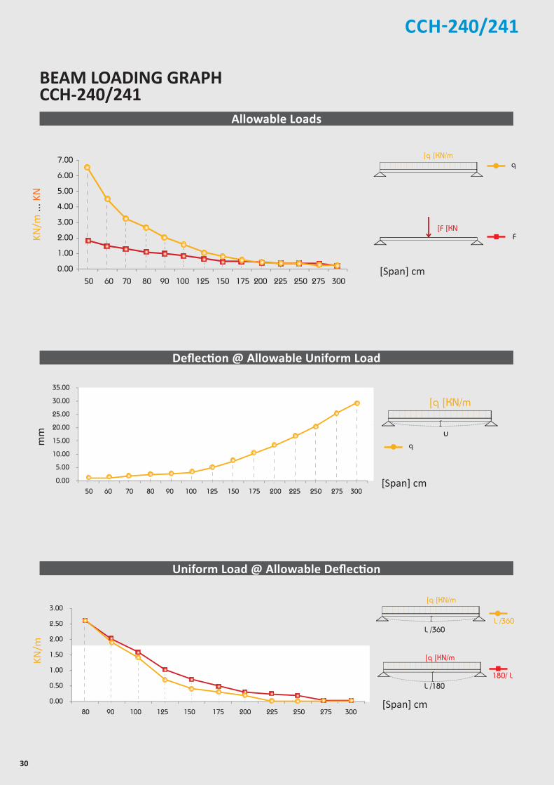
Uniform Load* @
Span (L) Allowable Load* Deflection L / 360 L / 180
[cm] q [kN/m] F [kN] U [mm] [L /X] q [kN/m] q [kN/m]
50 6.60 1.70 0.83 610 6.60 6.60
60 4.60 1.40 1.19 500 4.60 4.60
70 3.30 1.20 1.59 440 3.30 3.30
80 2.60 1.00 2.13 380 2.60 2.60
90 2.00 0.90 2.63 340 1.90 2.00
100 1.60 0.80 3.20 310 1.40 1.60
125 1.00 0.60 4.89 260 0.70 1.00
150 0.73 0.50 7.40 200 0.40 0.70
175 0.53 0.50 9.96 180 0.30 0.50
200 0.41 0.40 13.14 150 0.20 0.30
225 0.32 0.36 16.42 140 x 0.24
250 0.26 0.33 20.34 120 x 0.18
275 0.22 0.30 25.20 110 x x
300 0.18 0.27 29.20 100 x x
Thickness : 1.5 mmStandard Length : 3.00 m Finishes : Pre-Galvanized, Hot-Dip Galvanized.
Load table for single beam with uniform (characteristic) Live-LoadThis associated data are considered for perforated and non-perforated c-channel types according to DIN 18.800
30
CCH-240/241
BEAM LOADING GRAPH CCH-240/241
5.00
6.00
7.00
0.00
1.00
2.00
3.00
4.00
50 60 70 80 90 100 125 150 175 200 225 250 275 300
25.00
30.00
35.00
0.00
5.00
10.00
15.00
20.00
50 60 70 80 90 100 125 150 175 200 225 250 275 300
2.00
2.50
3.00
0.00
0.50
1.00
1.50
80 90 100 125 150 175 200 225 250 275 300
[Span] cm
[Span] cm
Allowable Loads
Deflection @ Allowable Uniform Load
Uniform Load @ Allowable Deflection
[Span] cm
mm
Chosen Material:Allowable Bending Stress 21,82 kN/cm²Allowable Shear Stress 12,60 kN/cm²Modulus of Elasticity 21.000 kN/cm²
40B = S 235 JRG2
C-Channel:Area of Shear (Az)
1,67 cm
Moment of Inertia (Iy)
5,87 cm
Moment of Inertia (Iz
y
z
)
8,76 cm
min. Section Modulus (Sy)
2,72 cm
Warping Constant (Iw)
171,52 cm
Torsional Constant (IT)
0,07 cm
Plastic Moment cap. (Mpl,y)
0,82 kNm
Self weight (G)
2,32 kg/m
C 41x41x2,52
4
4
3
6
4
cmcmcmcmcmcmkNmkg/m
2
4
4
3
6
4
C-Channel:Cross Section Area (A) cm2
Moment of Inertia (I ) cm4
4Moment of Inertia (I ) cmSelf Weight (G) kg/m
^
F
]q ]KN/m
]F ]KN
q
180/ L
Chosen Material:Allowable Bending Stress 21,82 kN/cm²Allowable Shear Stress 12,60 kN/cm²Modulus of Elasticity 21.000 kN/cm²
40B = S 235 JRG2
C-Channel:Area of Shear (Az)
1,67 cm
Moment of Inertia (Iy)
5,87 cm
Moment of Inertia (Iz
y
z
)
8,76 cm
min. Section Modulus (Sy)
2,72 cm
Warping Constant (Iw)
171,52 cm
Torsional Constant (IT)
0,07 cm
Plastic Moment cap. (Mpl,y)
0,82 kNm
Self weight (G)
2,32 kg/m
C 41x41x2,52
4
4
3
6
4
cmcmcmcmcmcmkNmkg/m
2
4
4
3
6
4
C-Channel:Cross Section Area (A) cm2
Moment of Inertia (I ) cm4
4Moment of Inertia (I ) cmSelf Weight (G) kg/m
^
L /360
Chosen Material:Allowable Bending Stress 21,82 kN/cm²Allowable Shear Stress 12,60 kN/cm²Modulus of Elasticity 21.000 kN/cm²
40B = S 235 JRG2
C-Channel:Area of Shear (Az)
1,67 cm
Moment of Inertia (Iy)
5,87 cm
Moment of Inertia (Iz
y
z
)
8,76 cm
min. Section Modulus (Sy)
2,72 cm
Warping Constant (Iw)
171,52 cm
Torsional Constant (IT)
0,07 cm
Plastic Moment cap. (Mpl,y)
0,82 kNm
Self weight (G)
2,32 kg/m
C 41x41x2,52
4
4
3
6
4
cmcmcmcmcmcmkNmkg/m
2
4
4
3
6
4
C-Channel:Cross Section Area (A) cm2
Moment of Inertia (I ) cm4
4Moment of Inertia (I ) cmSelf Weight (G) kg/m
^
L /180
]q ]KN/m
L /360
]q ]KN/m
Chosen Material:Allowable Bending Stress 21,82 kN/cm²Allowable Shear Stress 12,60 kN/cm²Modulus of Elasticity 21.000 kN/cm²
40B = S 235 JRG2
C-Channel:Area of Shear (Az)
1,67 cm
Moment of Inertia (Iy)
5,87 cm
Moment of Inertia (Iz
y
z
)
8,76 cm
min. Section Modulus (Sy)
2,72 cm
Warping Constant (Iw)
171,52 cm
Torsional Constant (IT)
0,07 cm
Plastic Moment cap. (Mpl,y)
0,82 kNm
Self weight (G)
2,32 kg/m
C 41x41x2,52
4
4
3
6
4
cmcmcmcmcmcmkNmkg/m
2
4
4
3
6
4
C-Channel:Cross Section Area (A) cm2
Moment of Inertia (I ) cm4
4Moment of Inertia (I ) cmSelf Weight (G) kg/m
^
u
]q ]KN/m
q
KN/m
KN/m
... K
N
31
CCH-240/241
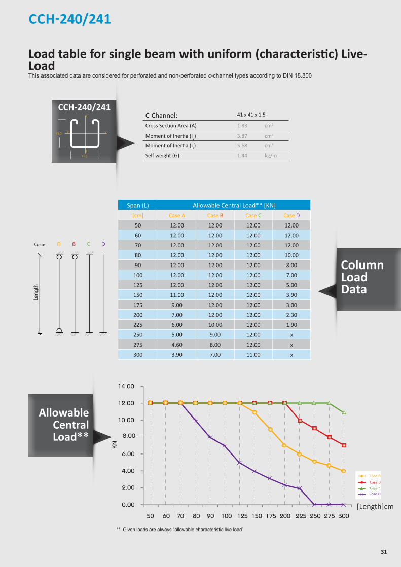
** Given loads are always “allowable characteristic live load”
allowable uniform Load
ACase:
Length
B C D
Leng
th
C-Channel: 41 x 41 x 1.5
Cross Section Area (A) 1.83 cm2
Moment of Inertia (Iy) 3.87 cm4
Moment of Inertia (Iz) 5.68 cm4
Self weight (G) 1.44 kg/m
Span (L) Allowable Central Load** [KN]
[cm] Case A Case B Case C Case D
50 12.00 12.00 12.00 12.00
60 12.00 12.00 12.00 12.00
70 12.00 12.00 12.00 12.00
80 12.00 12.00 12.00 10.00
90 12.00 12.00 12.00 8.00
100 12.00 12.00 12.00 7.00
125 12.00 12.00 12.00 5.00
150 11.00 12.00 12.00 3.90
175 9.00 12.00 12.00 3.00
200 7.00 12.00 12.00 2.30
225 6.00 10.00 12.00 1.90
250 5.00 9.00 12.00 x
275 4.60 8.00 12.00 x
300 3.90 7.00 11.00 x
10.00
8.00
12.00
14.00
0.00
2.00
4.00
6.00
50 60 70 80 90 100 125 150 175 200 225 250 275 300
KN
[Length]cm
Case A
Case B
Case CCase D
CCH-240/241
Allowable Central Load**
Column Load Data
Z
Z
YY
Z
Z
YY
Z
Z
YY
Z
Z
Y Y
21.0
7.0
41.0
21.0
41.0
22.0
42.0
7.0
41.0
22.0
41.0
7.0
41.0
41.0
41.0
22.0
82.0
7.0
41.0
22.0
50
30
13
Load table for single beam with uniform (characteristic) Live-LoadThis associated data are considered for perforated and non-perforated c-channel types according to DIN 18.800
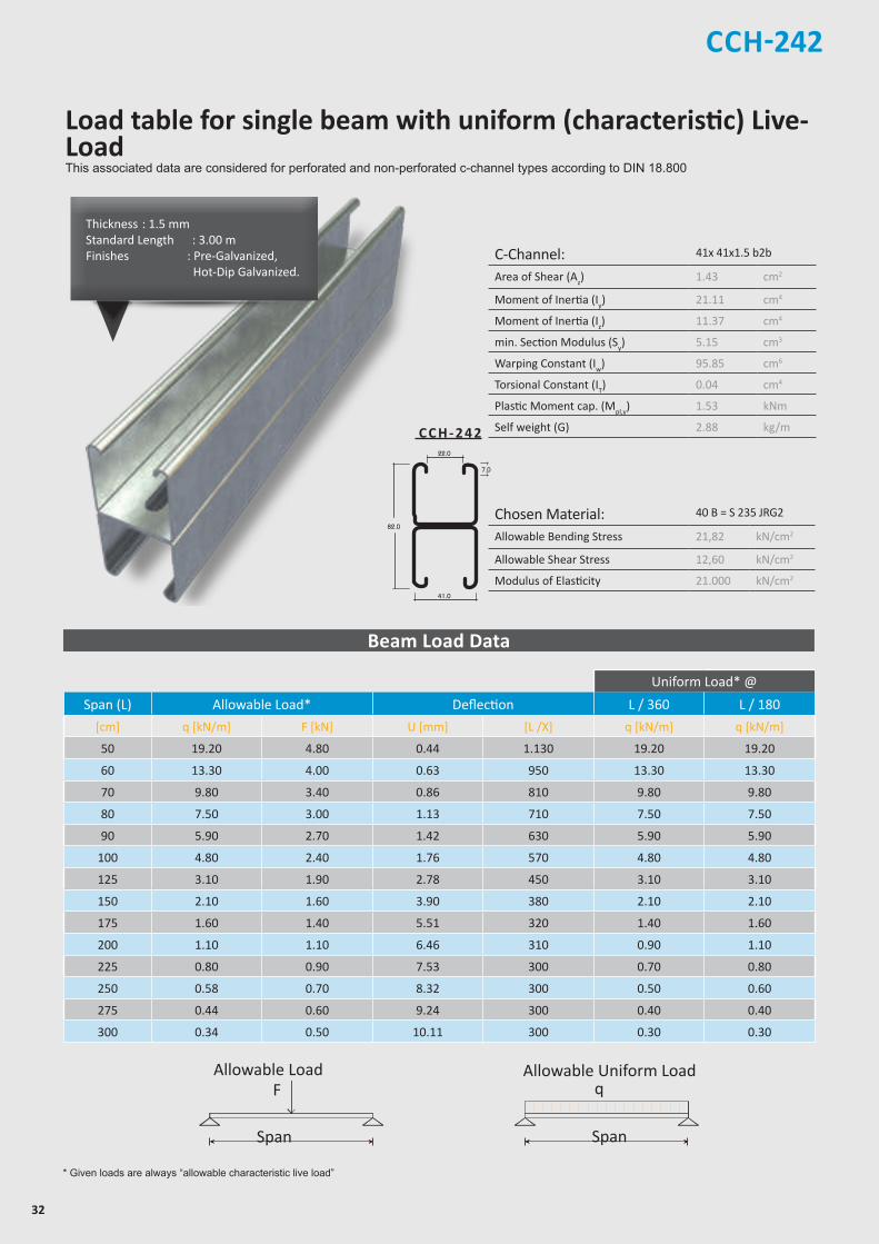
32
C-Channel: 41x 41x1.5 b2b
Area of Shear (Az) 1.43 cm2
Moment of Inertia (Iy) 21.11 cm4
Moment of Inertia (Iz) 11.37 cm4
min. Section Modulus (Sy) 5.15 cm3
Warping Constant (Iw) 95.85 cm6
Torsional Constant (IT) 0.04 cm4
Plastic Moment cap. (Mpl,y) 1.53 kNm
Self weight (G) 2.88 kg/m
Chosen Material: 40 B = S 235 JRG2
Allowable Bending Stress 21,82 kN/cm2
Allowable Shear Stress 12,60 kN/cm2
Modulus of Elasticity 21.000 kN/cm2
CCH-242
Z
Z
YY
Z
Z
YY
Z
Z
YY
Z
Z
Y Y
21.0
7.0
41.0
21.0
41.0
22.0
42.0
7.0
41.0
22.0
41.0
7.0
41.0
41.0
41.0
22.0
82.0
7.0
41.0
22.0
50
30
13
C C H - 2 4 2
* Given loads are always “allowable characteristic live load”
Beam Load Data
Uniform Load* @
Span (L) Allowable Load* Deflection L / 360 L / 180
[cm] q [kN/m] F [kN] U [mm] [L /X] q [kN/m] q [kN/m]
50 19.20 4.80 0.44 1.130 19.20 19.20
60 13.30 4.00 0.63 950 13.30 13.30
70 9.80 3.40 0.86 810 9.80 9.80
80 7.50 3.00 1.13 710 7.50 7.50
90 5.90 2.70 1.42 630 5.90 5.90
100 4.80 2.40 1.76 570 4.80 4.80
125 3.10 1.90 2.78 450 3.10 3.10
150 2.10 1.60 3.90 380 2.10 2.10
175 1.60 1.40 5.51 320 1.40 1.60
200 1.10 1.10 6.46 310 0.90 1.10
225 0.80 0.90 7.53 300 0.70 0.80
250 0.58 0.70 8.32 300 0.50 0.60
275 0.44 0.60 9.24 300 0.40 0.40
300 0.34 0.50 10.11 300 0.30 0.30
Chosen Material:Allowable Bending Stress 21,82 kN/cm²Allowable Shear Stress 12,60 kN/cm²Modulus of Elasticity 21.000 kN/cm²
40B = S 235 JRG2
C-Channel:Area of Shear (Az)
1,67 cm
Moment of Inertia (Iy)
5,87 cm
Moment of Inertia (Iz
y
z
)
8,76 cm
min. Section Modulus (Sy)
2,72 cm
Warping Constant (Iw)
171,52 cm
Torsional Constant (IT)
0,07 cm
Plastic Moment cap. (Mpl,y)
0,82 kNm
Self weight (G)
2,32 kg/m
C 41x41x2,52
4
4
3
6
4
cmcmcmcmcmcmkNmkg/m
2
4
4
3
6
4
C-Channel:Cross Section Area (A) cm2
Moment of Inertia (I ) cm4
4Moment of Inertia (I ) cmSelf Weight (G) kg/m
^
Allowable Load
Span
F
Chosen Material:Allowable Bending Stress 21,82 kN/cm²Allowable Shear Stress 12,60 kN/cm²Modulus of Elasticity 21.000 kN/cm²
40B = S 235 JRG2
C-Channel:Area of Shear (Az)
1,67 cm
Moment of Inertia (Iy)
5,87 cm
Moment of Inertia (Iz
y
z
)
8,76 cm
min. Section Modulus (Sy)
2,72 cm
Warping Constant (Iw)
171,52 cm
Torsional Constant (IT)
0,07 cm
Plastic Moment cap. (Mpl,y)
0,82 kNm
Self weight (G)
2,32 kg/m
C 41x41x2,52
4
4
3
6
4
cmcmcmcmcmcmkNmkg/m
2
4
4
3
6
4
C-Channel:Cross Section Area (A) cm2
Moment of Inertia (I ) cm4
4Moment of Inertia (I ) cmSelf Weight (G) kg/m
^
Allowable Uniform Load
Span
q
Thickness : 1.5 mmStandard Length : 3.00 m Finishes : Pre-Galvanized, Hot-Dip Galvanized.
Load table for single beam with uniform (characteristic) Live-LoadThis associated data are considered for perforated and non-perforated c-channel types according to DIN 18.800

33
CCH-242
20.00
25.00
0.00
5.00
10.00
15.00
50 60 70 80 90 100 125 150 175 200 225 250 275 300
8.00
10.00
12.00
0.00
2.00
4.00
6.00
50 60 70 80 90 100 125 150 175 200 225 250 275 300
5.00
6.00
7.00
8.00
0.00
1.00
2.00
3.00
4.00
80 90 100 125 150 175 200 225 250 275 300
[Span] cm
Allowable Loads
Deflection @ Allowable Uniform Load
Uniform Load @ Allowable Deflection
[Span] cm
[Span] cm
mm
Chosen Material:Allowable Bending Stress 21,82 kN/cm²Allowable Shear Stress 12,60 kN/cm²Modulus of Elasticity 21.000 kN/cm²
40B = S 235 JRG2
C-Channel:Area of Shear (Az)
1,67 cm
Moment of Inertia (Iy)
5,87 cm
Moment of Inertia (Iz
y
z
)
8,76 cm
min. Section Modulus (Sy)
2,72 cm
Warping Constant (Iw)
171,52 cm
Torsional Constant (IT)
0,07 cm
Plastic Moment cap. (Mpl,y)
0,82 kNm
Self weight (G)
2,32 kg/m
C 41x41x2,52
4
4
3
6
4
cmcmcmcmcmcmkNmkg/m
2
4
4
3
6
4
C-Channel:Cross Section Area (A) cm2
Moment of Inertia (I ) cm4
4Moment of Inertia (I ) cmSelf Weight (G) kg/m
^
Chosen Material:Allowable Bending Stress 21,82 kN/cm²Allowable Shear Stress 12,60 kN/cm²Modulus of Elasticity 21.000 kN/cm²
40B = S 235 JRG2
C-Channel:Area of Shear (Az)
1,67 cm
Moment of Inertia (Iy)
5,87 cm
Moment of Inertia (Iz
y
z
)
8,76 cm
min. Section Modulus (Sy)
2,72 cm
Warping Constant (Iw)
171,52 cm
Torsional Constant (IT)
0,07 cm
Plastic Moment cap. (Mpl,y)
0,82 kNm
Self weight (G)
2,32 kg/m
C 41x41x2,52
4
4
3
6
4
cmcmcmcmcmcmkNmkg/m
2
4
4
3
6
4
C-Channel:Cross Section Area (A) cm2
Moment of Inertia (I ) cm4
4Moment of Inertia (I ) cmSelf Weight (G) kg/m
^
F
]q ]KN/m
]F ]KN
q
180/ L
Chosen Material:Allowable Bending Stress 21,82 kN/cm²Allowable Shear Stress 12,60 kN/cm²Modulus of Elasticity 21.000 kN/cm²
40B = S 235 JRG2
C-Channel:Area of Shear (Az)
1,67 cm
Moment of Inertia (Iy)
5,87 cm
Moment of Inertia (Iz
y
z
)
8,76 cm
min. Section Modulus (Sy)
2,72 cm
Warping Constant (Iw)
171,52 cm
Torsional Constant (IT)
0,07 cm
Plastic Moment cap. (Mpl,y)
0,82 kNm
Self weight (G)
2,32 kg/m
C 41x41x2,52
4
4
3
6
4
cmcmcmcmcmcmkNmkg/m
2
4
4
3
6
4
C-Channel:Cross Section Area (A) cm2
Moment of Inertia (I ) cm4
4Moment of Inertia (I ) cmSelf Weight (G) kg/m
^
L /360
Chosen Material:Allowable Bending Stress 21,82 kN/cm²Allowable Shear Stress 12,60 kN/cm²Modulus of Elasticity 21.000 kN/cm²
40B = S 235 JRG2
C-Channel:Area of Shear (Az)
1,67 cm
Moment of Inertia (Iy)
5,87 cm
Moment of Inertia (Iz
y
z
)
8,76 cm
min. Section Modulus (Sy)
2,72 cm
Warping Constant (Iw)
171,52 cm
Torsional Constant (IT)
0,07 cm
Plastic Moment cap. (Mpl,y)
0,82 kNm
Self weight (G)
2,32 kg/m
C 41x41x2,52
4
4
3
6
4
cmcmcmcmcmcmkNmkg/m
2
4
4
3
6
4
C-Channel:Cross Section Area (A) cm2
Moment of Inertia (I ) cm4
4Moment of Inertia (I ) cmSelf Weight (G) kg/m
^
L /180
]q ]KN/m
L /360
]q ]KN/m
Chosen Material:Allowable Bending Stress 21,82 kN/cm²Allowable Shear Stress 12,60 kN/cm²Modulus of Elasticity 21.000 kN/cm²
40B = S 235 JRG2
C-Channel:Area of Shear (Az)
1,67 cm
Moment of Inertia (Iy)
5,87 cm
Moment of Inertia (Iz
y
z
)
8,76 cm
min. Section Modulus (Sy)
2,72 cm
Warping Constant (Iw)
171,52 cm
Torsional Constant (IT)
0,07 cm
Plastic Moment cap. (Mpl,y)
0,82 kNm
Self weight (G)
2,32 kg/m
C 41x41x2,52
4
4
3
6
4
cmcmcmcmcmcmkNmkg/m
2
4
4
3
6
4
C-Channel:Cross Section Area (A) cm2
Moment of Inertia (I ) cm4
4Moment of Inertia (I ) cmSelf Weight (G) kg/m
^
u
]q ]KN/m
q
KN/m
... K
NKN
/m
BEAM LOADING GRAPH CCH-242
34
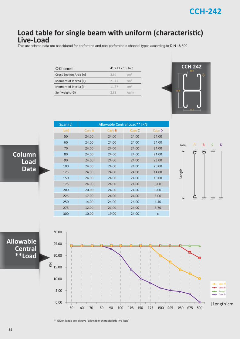
CCH-242
Column LoadData
CCH-242Z
Z
YY
Z
Z
YY
Z
Z
YY
Z
Z
Y Y
21.0
7.0
41.0
21.0
41.0
22.0
42.0
7.0
41.0
22.0
41.0
7.0
41.0
41.0
41.0
22.0
82.0
7.0
41.0
22.0
50
30
13
allowable uniform Load
ACase:
Length
B C D
Leng
th
C-Channel: 41 x 41 x 1.5 b2b
Cross Section Area (A) 3.67 cm2
Moment of Inertia (Iy) 21.11 cm4
Moment of Inertia (Iz) 11.37 cm4
Self weight (G) 2.88 kg/m
Span (L) Allowable Central Load** [KN]
[cm] Case A Case B Case C Case D
50 24.00 24.00 24.00 24.00
60 24.00 24.00 24.00 24.00
70 24.00 24.00 24.00 24.00
80 24.00 24.00 24.00 24.00
90 24.00 24.00 24.00 23.00
100 24.00 24.00 24.00 20.00
125 24.00 24.00 24.00 14.00
150 24.00 24.00 24.00 10.00
175 24.00 24.00 24.00 8.00
200 20.00 24.00 24.00 6.00
225 17.00 24.00 24.00 5.00
250 14.00 24.00 24.00 4.40
275 12.00 21.00 24.00 3.70
300 10.00 19.00 24.00 x
** Given loads are always “allowable characteristic live load”
20.00
25.00
30.00
0.00
5.00
10.00
15.00
50 60 70 80 90 100 125 150 175 200 225 250 275 300
KN
[Length]cm
Case A
Case B
Case CCase D
Load table for single beam with uniform (characteristic) Live-LoadThis associated data are considered for perforated and non-perforated c-channel types according to DIN 18.800
Allowable Central**Load

35
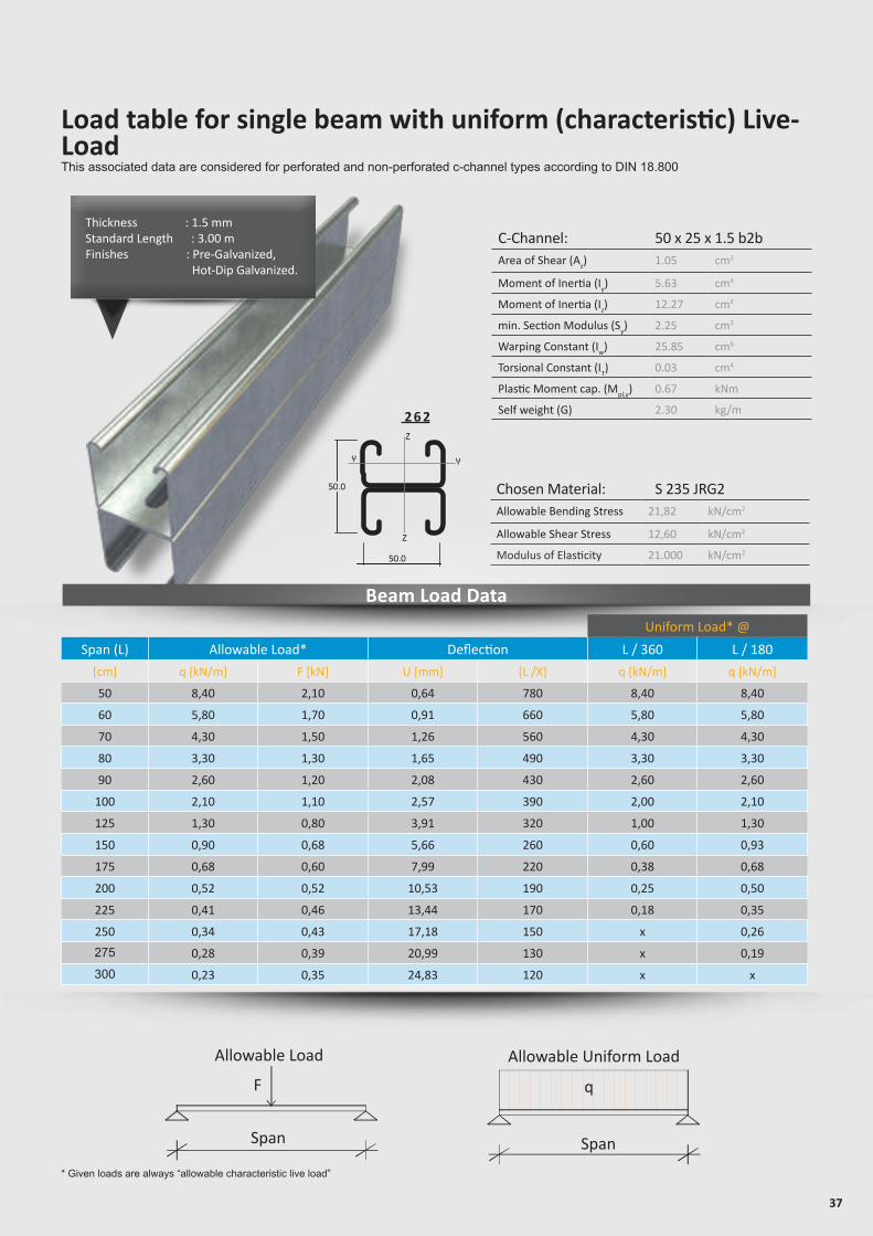
Load table for single beam with uniform (characteristic) Live-LoadThis associated data are considered for perforated and non-perforated c-channel types according to DIN 18.800
* Given loads are always “allowable characteristic live load”
Allowable Load
Span
F
Allowable Uniform Load
Span
q
C-Channel: 50 x 25 x 1.5Area of Shear (Az) 0.52 cm2
Moment of Inertia (Iy) 1.19 cm4
Moment of Inertia (Iz) 6.13 cm4
min. Section Modulus (Sy) 0.83 cm3
Warping Constant (Iw) 40.86 cm6
Torsional Constant (IT) 0.01 cm4
Plastic Moment cap. (Mpl,y) 0.26 kNm
Self weight (G) 1.20 kg/m
Chosen Material: S 235 JRG2Allowable Bending Stress 21,82 kN/cm2
Allowable Shear Stress 12,60 kN/cm2
Modulus of Elasticity 21.000 kN/cm2
Thickness : 1.5 mmStandard Length : 3.00 m Finishes : Pre-Galvanized, Hot-Dip Galvanized.
C C H - 2 2 1
Beam Load Data
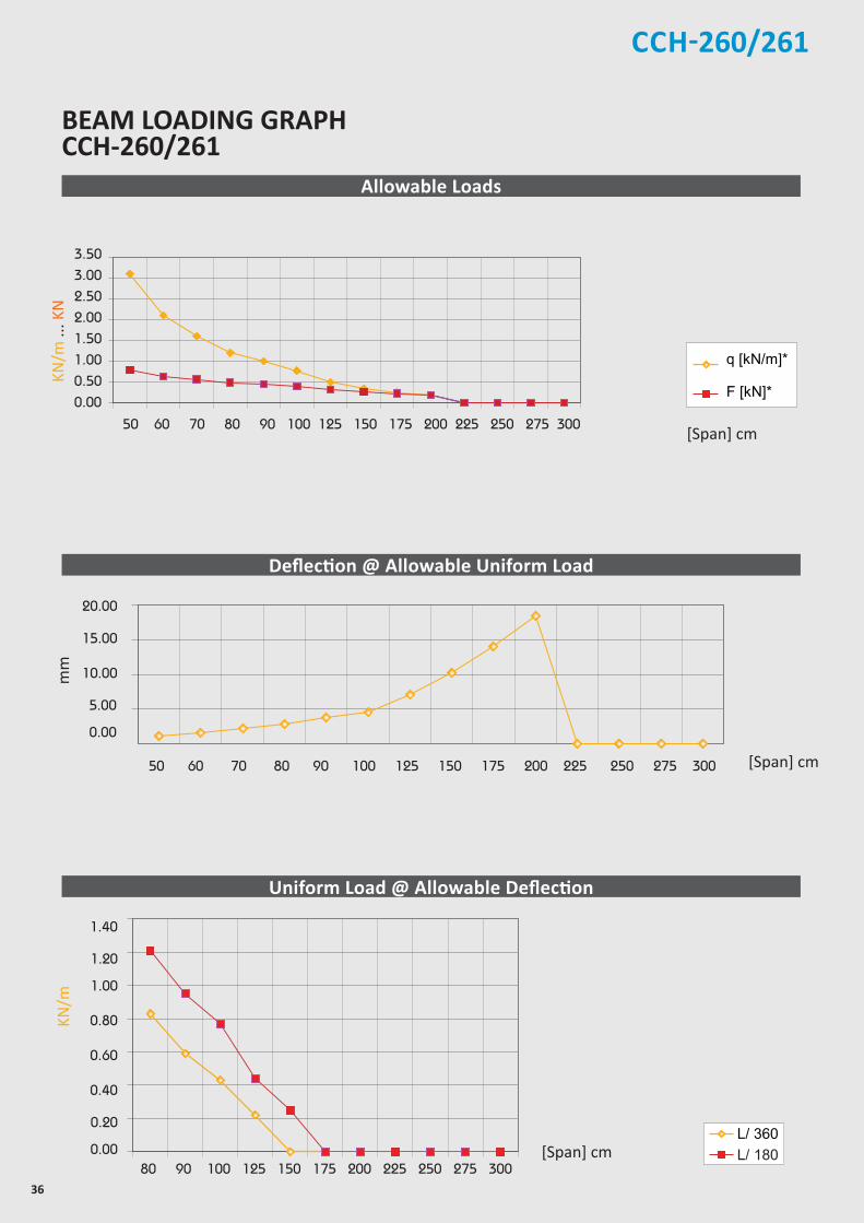
CCH-260/261
Uniform Load* @
Span (L) Allowable Load* Deflection L / 360 L / 180
[cm] q [kN/m] F [kN] U [mm] [L /X] q [kN/m] q [kN/m]
30 8.60 1.30 0.40 750 8.60 8.60
40 4.80 1.00 0.71 570 4.80 4.80
50 3.10 0.78 1.11 450 3.09 3.09
60 2.10 0.63 1.57 380 1.97 2.15
70 1.60 0.56 2.22 320 1.24 1.58
80 1.20 0.48 2.85 280 0.83 1.21
90 1.00 0.45 3.81 240 0.59 0.95
100 0.77 0.39 4.48 220 0.43 0.77
125 0.49 0.31 7.02 180 0.22 0.44
150 0.34 0.26 10.21 150 x 0.25
175 0.25 0.22 14.08 120 x x
200 0.19 0.19 18.52 110 x x
225 x x x x x x
250 x x x x x x
275 x x x x x x
300 x x x x x x
36
CCH-260/261
[Span] cm
BEAM LOADING GRAPH CCH-260/261
[Span] cm
Allowable Loads
Deflection @ Allowable Uniform Load
Uniform Load @ Allowable Deflection
[Span] cm
mm
KN/m
KN/m
... K
N
37
Load table for single beam with uniform (characteristic) Live-LoadThis associated data are considered for perforated and non-perforated c-channel types according to DIN 18.800
* Given loads are always “allowable characteristic live load”
Allowable Load
Span
F
Allowable Uniform Load
Span
q
C-Channel: 50 x 25 x 1.5 b2bArea of Shear (Az) 1.05 cm2
Moment of Inertia (Iy) 5.63 cm4
Moment of Inertia (Iz) 12.27 cm4
min. Section Modulus (Sy) 2.25 cm3
Warping Constant (Iw) 25.85 cm6
Torsional Constant (IT) 0.03 cm4
Plastic Moment cap. (Mpl,y) 0.67 kNm
Self weight (G) 2.30 kg/m
Chosen Material: S 235 JRG2Allowable Bending Stress 21,82 kN/cm2
Allowable Shear Stress 12,60 kN/cm2
Modulus of Elasticity 21.000 kN/cm2
Beam Load Data
Uniform Load* @
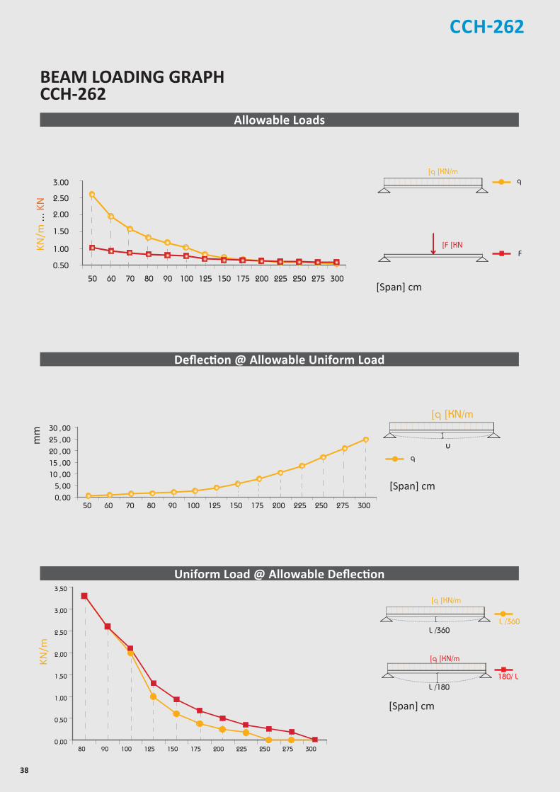
Span (L) Allowable Load* Deflection L / 360 L / 180
[cm] q [kN/m] F [kN] U [mm] [L /X] q [kN/m] q [kN/m]
50 8,40 2,10 0,64 780 8,40 8,40
60 5,80 1,70 0,91 660 5,80 5,80
70 4,30 1,50 1,26 560 4,30 4,30
80 3,30 1,30 1,65 490 3,30 3,30
90 2,60 1,20 2,08 430 2,60 2,60
100 2,10 1,10 2,57 390 2,00 2,10
125 1,30 0,80 3,91 320 1,00 1,30
150 0,90 0,68 5,66 260 0,60 0,93
175 0,68 0,60 7,99 220 0,38 0,68
200 0,52 0,52 10,53 190 0,25 0,50
225 0,41 0,46 13,44 170 0,18 0,35
250 0,34 0,43 17,18 150 x 0,26
275 0,28 0,39 20,99 130 x 0,19
300 0,23 0,35 24,83 120 x x
2 6 2
Thickness : 1.5 mmStandard Length : 3.00 m Finishes : Pre-Galvanized, Hot-Dip Galvanized.
38
CCH-262
[Span] cm
Allowable Loads
Deflection @ Allowable Uniform Load
Uniform Load @ Allowable Deflection
[Span] cm
mm
[Span] cm
Chosen Material:Allowable Bending Stress 21,82 kN/cm²Allowable Shear Stress 12,60 kN/cm²Modulus of Elasticity 21.000 kN/cm²
40B = S 235 JRG2
C-Channel:Area of Shear (Az)
1,67 cm
Moment of Inertia (Iy)
5,87 cm
Moment of Inertia (Iz
y
z
)
8,76 cm
min. Section Modulus (Sy)
2,72 cm
Warping Constant (Iw)
171,52 cm
Torsional Constant (IT)
0,07 cm
Plastic Moment cap. (Mpl,y)
0,82 kNm
Self weight (G)
2,32 kg/m
C 41x41x2,52
4
4
3
6
4
cmcmcmcmcmcmkNmkg/m
2
4
4
3
6
4
C-Channel:Cross Section Area (A) cm2
Moment of Inertia (I ) cm4
4Moment of Inertia (I ) cmSelf Weight (G) kg/m
^
F
]q ]KN/m
]F ]KN
q
180/ L
Chosen Material:Allowable Bending Stress 21,82 kN/cm²Allowable Shear Stress 12,60 kN/cm²Modulus of Elasticity 21.000 kN/cm²
40B = S 235 JRG2
C-Channel:Area of Shear (Az)
1,67 cm
Moment of Inertia (Iy)
5,87 cm
Moment of Inertia (Iz
y
z
)
8,76 cm
min. Section Modulus (Sy)
2,72 cm
Warping Constant (Iw)
171,52 cm
Torsional Constant (IT)
0,07 cm
Plastic Moment cap. (Mpl,y)
0,82 kNm
Self weight (G)
2,32 kg/m
C 41x41x2,52
4
4
3
6
4
cmcmcmcmcmcmkNmkg/m
2
4
4
3
6
4
C-Channel:Cross Section Area (A) cm2
Moment of Inertia (I ) cm4
4Moment of Inertia (I ) cmSelf Weight (G) kg/m
^
L /360
Chosen Material:Allowable Bending Stress 21,82 kN/cm²Allowable Shear Stress 12,60 kN/cm²Modulus of Elasticity 21.000 kN/cm²
40B = S 235 JRG2
C-Channel:Area of Shear (Az)
1,67 cm
Moment of Inertia (Iy)
5,87 cm
Moment of Inertia (Iz
y
z
)
8,76 cm
min. Section Modulus (Sy)
2,72 cm
Warping Constant (Iw)
171,52 cm
Torsional Constant (IT)
0,07 cm
Plastic Moment cap. (Mpl,y)
0,82 kNm
Self weight (G)
2,32 kg/m
C 41x41x2,52
4
4
3
6
4
cmcmcmcmcmcmkNmkg/m
2
4
4
3
6
4
C-Channel:Cross Section Area (A) cm2
Moment of Inertia (I ) cm4
4Moment of Inertia (I ) cmSelf Weight (G) kg/m
^
L /180
]q ]KN/m
L /360
]q ]KN/m
Chosen Material:Allowable Bending Stress 21,82 kN/cm²Allowable Shear Stress 12,60 kN/cm²Modulus of Elasticity 21.000 kN/cm²
40B = S 235 JRG2
C-Channel:Area of Shear (Az)
1,67 cm
Moment of Inertia (Iy)
5,87 cm
Moment of Inertia (Iz
y
z
)
8,76 cm
min. Section Modulus (Sy)
2,72 cm
Warping Constant (Iw)
171,52 cm
Torsional Constant (IT)
0,07 cm
Plastic Moment cap. (Mpl,y)
0,82 kNm
Self weight (G)
2,32 kg/m
C 41x41x2,52
4
4
3
6
4
cmcmcmcmcmcmkNmkg/m
2
4
4
3
6
4
C-Channel:Cross Section Area (A) cm2
Moment of Inertia (I ) cm4
4Moment of Inertia (I ) cmSelf Weight (G) kg/m
^
u
]q ]KN/m
q
KN/m
BEAM LOADING GRAPHCCH-262
KN/m
... K
N
39
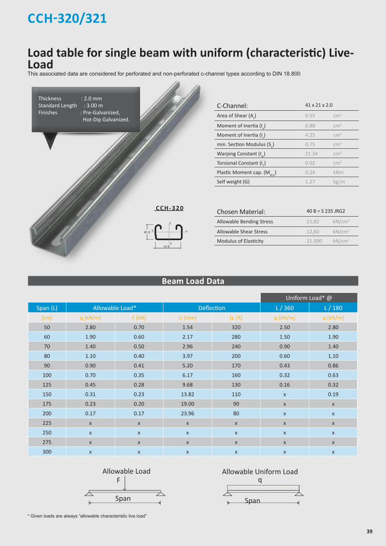
CCH-320/321
Z
Z
YY
Z
Z
YY
Z
Z
YY
Z
Z
Y Y
21.0
7.0
41.0
21.0
41.0
22.0
42.0
7.0
41.0
22.0
41.0
7.0
41.0
41.0
41.0
22.0
82.0
7.0
41.0
22.0
50
30
13
* Given loads are always “allowable characteristic live load”
Beam Load Data
C-Channel: 41 x 21 x 2.0
Area of Shear (Az) 0.55 cm2
Moment of Inertia (Iy) 0.88 cm4
Moment of Inertia (Iz) 4.25 cm4
min. Section Modulus (Sy) 0.75 cm3
Warping Constant (Iw) 21.34 cm6
Torsional Constant (IT) 0.02 cm4
Plastic Moment cap. (Mpl,y) 0.24 kNm
Self weight (G) 1.27 kg/m
Chosen Material: 40 B = S 235 JRG2
Allowable Bending Stress 21,82 kN/cm2
Allowable Shear Stress 12,60 kN/cm2
Modulus of Elasticity 21.000 kN/cm2
C C H - 3 2 0
Uniform Load* @
Span (L) Allowable Load* Deflection L / 360 L / 180
[cm] q [kN/m] F [kN] U [mm] [L /X] q [kN/m] q [kN/m]
50 2.80 0.70 1.54 320 2.50 2.80
60 1.90 0.60 2.17 280 1.50 1.90
70 1.40 0.50 2.96 240 0.90 1.40
80 1.10 0.40 3.97 200 0.60 1.10
90 0.90 0.41 5.20 170 0.43 0.86
100 0.70 0.35 6.17 160 0.32 0.63
125 0.45 0.28 9.68 130 0.16 0.32
150 0.31 0.23 13.82 110 x 0.19
175 0.23 0.20 19.00 90 x x
200 0.17 0.17 23.96 80 x x
225 x x x x x x
250 x x x x x x
275 x x x x x x
300 x x x x x x
Chosen Material:Allowable Bending Stress 21,82 kN/cm²Allowable Shear Stress 12,60 kN/cm²Modulus of Elasticity 21.000 kN/cm²
40B = S 235 JRG2
C-Channel:Area of Shear (Az)
1,67 cm
Moment of Inertia (Iy)
5,87 cm
Moment of Inertia (Iz
y
z
)
8,76 cm
min. Section Modulus (Sy)
2,72 cm
Warping Constant (Iw)
171,52 cm
Torsional Constant (IT)
0,07 cm
Plastic Moment cap. (Mpl,y)
0,82 kNm
Self weight (G)
2,32 kg/m
C 41x41x2,52
4
4
3
6
4
cmcmcmcmcmcmkNmkg/m
2
4
4
3
6
4
C-Channel:Cross Section Area (A) cm2
Moment of Inertia (I ) cm4
4Moment of Inertia (I ) cmSelf Weight (G) kg/m
^
Allowable Load
Span
F
Chosen Material:Allowable Bending Stress 21,82 kN/cm²Allowable Shear Stress 12,60 kN/cm²Modulus of Elasticity 21.000 kN/cm²
40B = S 235 JRG2
C-Channel:Area of Shear (Az)
1,67 cm
Moment of Inertia (Iy)
5,87 cm
Moment of Inertia (Iz
y
z
)
8,76 cm
min. Section Modulus (Sy)
2,72 cm
Warping Constant (Iw)
171,52 cm
Torsional Constant (IT)
0,07 cm
Plastic Moment cap. (Mpl,y)
0,82 kNm
Self weight (G)
2,32 kg/m
C 41x41x2,52
4
4
3
6
4
cmcmcmcmcmcmkNmkg/m
2
4
4
3
6
4
C-Channel:Cross Section Area (A) cm2
Moment of Inertia (I ) cm4
4Moment of Inertia (I ) cmSelf Weight (G) kg/m
^
Allowable Uniform Load
Span
q
Thickness : 2.0 mmStandard Length : 3.00 m Finishes : Pre-Galvanized, Hot-Dip Galvanized.
Load table for single beam with uniform (characteristic) Live-LoadThis associated data are considered for perforated and non-perforated c-channel types according to DIN 18.800
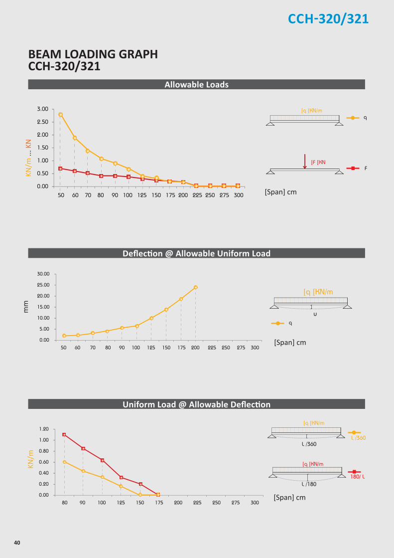
40
CCH-320/321
2.00
2.50
3.00
0.00
0.50
1.00
1.50
50 60 70 80 90 100 125 150 175 200 225 250 275 300
20.00
25.00
30.00
0.00
5.00
10.00
15.00
50 60 70 80 90 100 125 150 175 200 225 250 275 300
0.80
1.00
1.20
0.00
0.20
0.40
0.60
80 90 100 125 150 175 200 225 250 275 300
[Span] cm
[Span] cm
Allowable Loads
Deflection @ Allowable Uniform Load
Uniform Load @ Allowable Deflection
[Span] cm
mm
Chosen Material:Allowable Bending Stress 21,82 kN/cm²Allowable Shear Stress 12,60 kN/cm²Modulus of Elasticity 21.000 kN/cm²
40B = S 235 JRG2
C-Channel:Area of Shear (Az)
1,67 cm
Moment of Inertia (Iy)
5,87 cm
Moment of Inertia (Iz
y
z
)
8,76 cm
min. Section Modulus (Sy)
2,72 cm
Warping Constant (Iw)
171,52 cm
Torsional Constant (IT)
0,07 cm
Plastic Moment cap. (Mpl,y)
0,82 kNm
Self weight (G)
2,32 kg/m
C 41x41x2,52
4
4
3
6
4
cmcmcmcmcmcmkNmkg/m
2
4
4
3
6
4
C-Channel:Cross Section Area (A) cm2
Moment of Inertia (I ) cm4
4Moment of Inertia (I ) cmSelf Weight (G) kg/m
^
F
]q ]KN/m
]F ]KN
q
180/ L
Chosen Material:Allowable Bending Stress 21,82 kN/cm²Allowable Shear Stress 12,60 kN/cm²Modulus of Elasticity 21.000 kN/cm²
40B = S 235 JRG2
C-Channel:Area of Shear (Az)
1,67 cm
Moment of Inertia (Iy)
5,87 cm
Moment of Inertia (Iz
y
z
)
8,76 cm
min. Section Modulus (Sy)
2,72 cm
Warping Constant (Iw)
171,52 cm
Torsional Constant (IT)
0,07 cm
Plastic Moment cap. (Mpl,y)
0,82 kNm
Self weight (G)
2,32 kg/m
C 41x41x2,52
4
4
3
6
4
cmcmcmcmcmcmkNmkg/m
2
4
4
3
6
4
C-Channel:Cross Section Area (A) cm2
Moment of Inertia (I ) cm4
4Moment of Inertia (I ) cmSelf Weight (G) kg/m
^
L /360
Chosen Material:Allowable Bending Stress 21,82 kN/cm²Allowable Shear Stress 12,60 kN/cm²Modulus of Elasticity 21.000 kN/cm²
40B = S 235 JRG2
C-Channel:Area of Shear (Az)
1,67 cm
Moment of Inertia (Iy)
5,87 cm
Moment of Inertia (Iz
y
z
)
8,76 cm
min. Section Modulus (Sy)
2,72 cm
Warping Constant (Iw)
171,52 cm
Torsional Constant (IT)
0,07 cm
Plastic Moment cap. (Mpl,y)
0,82 kNm
Self weight (G)
2,32 kg/m
C 41x41x2,52
4
4
3
6
4
cmcmcmcmcmcmkNmkg/m
2
4
4
3
6
4
C-Channel:Cross Section Area (A) cm2
Moment of Inertia (I ) cm4
4Moment of Inertia (I ) cmSelf Weight (G) kg/m
^
L /180
]q ]KN/m
L /360
]q ]KN/m
Chosen Material:Allowable Bending Stress 21,82 kN/cm²Allowable Shear Stress 12,60 kN/cm²Modulus of Elasticity 21.000 kN/cm²
40B = S 235 JRG2
C-Channel:Area of Shear (Az)
1,67 cm
Moment of Inertia (Iy)
5,87 cm
Moment of Inertia (Iz
y
z
)
8,76 cm
min. Section Modulus (Sy)
2,72 cm
Warping Constant (Iw)
171,52 cm
Torsional Constant (IT)
0,07 cm
Plastic Moment cap. (Mpl,y)
0,82 kNm
Self weight (G)
2,32 kg/m
C 41x41x2,52
4
4
3
6
4
cmcmcmcmcmcmkNmkg/m
2
4
4
3
6
4
C-Channel:Cross Section Area (A) cm2
Moment of Inertia (I ) cm4
4Moment of Inertia (I ) cmSelf Weight (G) kg/m
^
u
]q ]KN/m
q
KN/m
KN/m
... K
N
BEAM LOADING GRAPH CCH-320/321
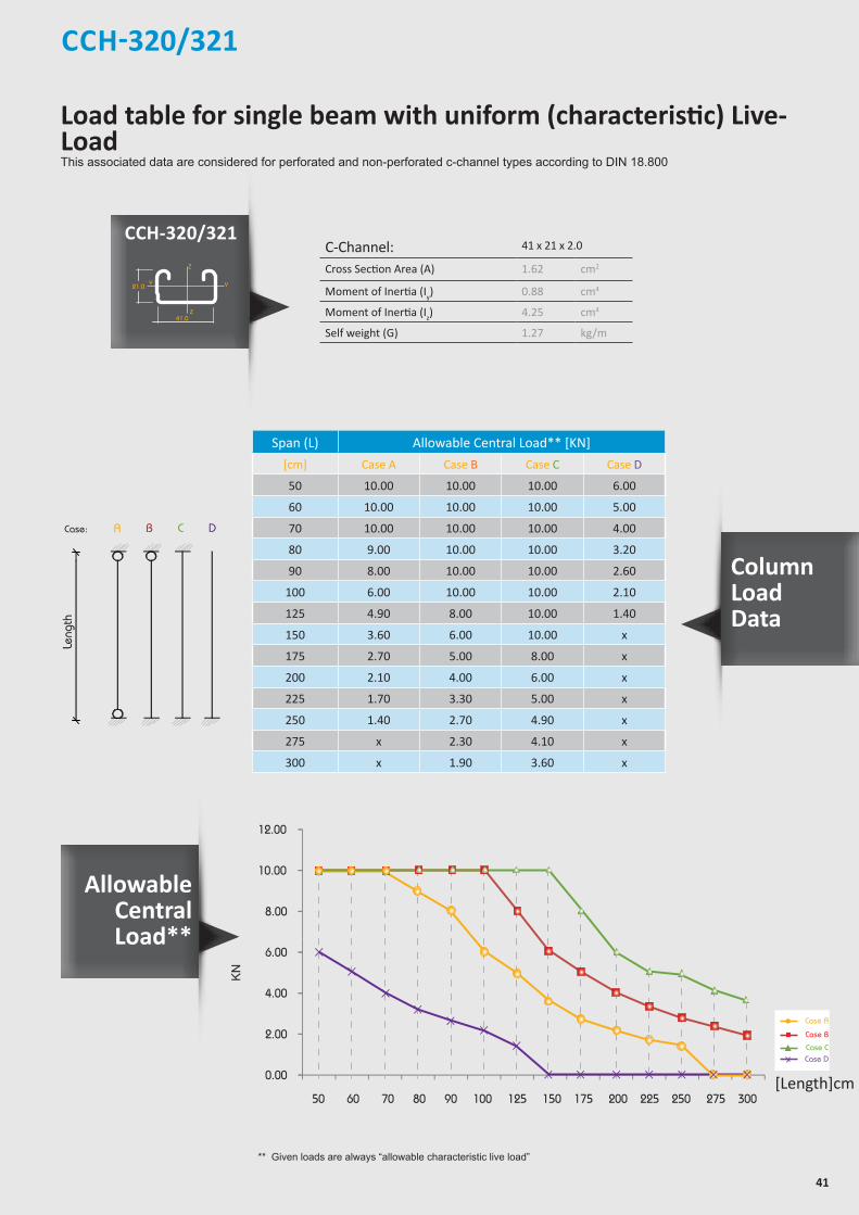
41
CCH-320/321
** Given loads are always “allowable characteristic live load”
allowable uniform Load
ACase:
Length
B C D
Leng
th
C-Channel: 41 x 21 x 2.0
Cross Section Area (A) 1.62 cm2
Moment of Inertia (Iy) 0.88 cm4
Moment of Inertia (Iz) 4.25 cm4
Self weight (G) 1.27 kg/m
Span (L) Allowable Central Load** [KN]
[cm] Case A Case B Case C Case D
50 10.00 10.00 10.00 6.00
60 10.00 10.00 10.00 5.00
70 10.00 10.00 10.00 4.00
80 9.00 10.00 10.00 3.20
90 8.00 10.00 10.00 2.60
100 6.00 10.00 10.00 2.10
125 4.90 8.00 10.00 1.40
150 3.60 6.00 10.00 x
175 2.70 5.00 8.00 x
200 2.10 4.00 6.00 x
225 1.70 3.30 5.00 x
250 1.40 2.70 4.90 x
275 x 2.30 4.10 x
300 x 1.90 3.60 x
8.00
10.00
12.00
0.00
2.00
4.00
6.00
50 60 70 80 90 100 125 150 175 200 225 250 275 300
KN
[Length]cm
Case A
Case B
Case CCase D
CCH-320/321
Allowable Central Load**
Column Load Data
Z
Z
YY
Z
Z
YY
Z
Z
YY
Z
Z
Y Y
21.0
7.0
41.0
21.0
41.0
22.0
42.0
7.0
41.0
22.0
41.0
7.0
41.0
41.0
41.0
22.0
82.0
7.0
41.0
22.0
50
30
13
Load table for single beam with uniform (characteristic) Live-LoadThis associated data are considered for perforated and non-perforated c-channel types according to DIN 18.800
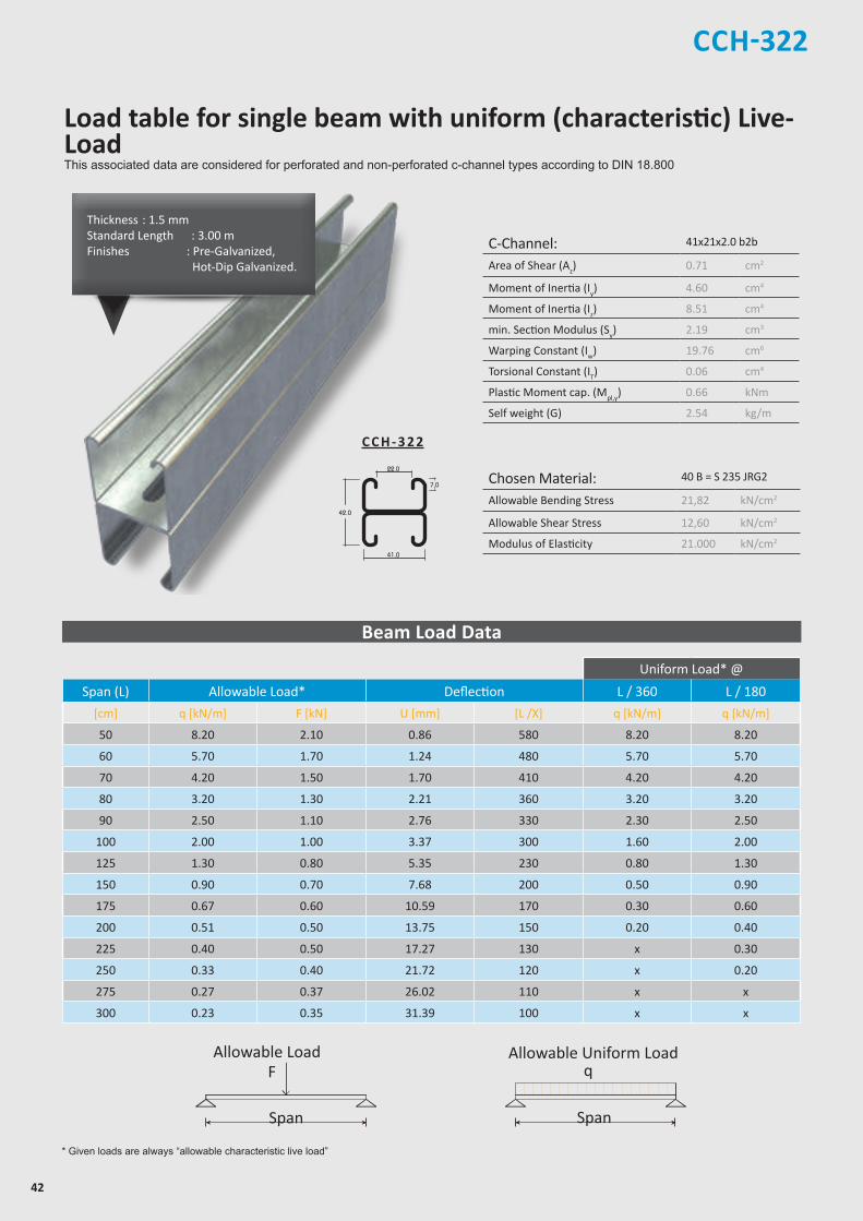
42
C-Channel: 41x21x2.0 b2b
Area of Shear (Az) 0.71 cm2
Moment of Inertia (Iy) 4.60 cm4
Moment of Inertia (Iz) 8.51 cm4
min. Section Modulus (Sy) 2.19 cm3
Warping Constant (Iw) 19.76 cm6
Torsional Constant (IT) 0.06 cm4
Plastic Moment cap. (Mpl,y) 0.66 kNm
Self weight (G) 2.54 kg/m
Chosen Material: 40 B = S 235 JRG2
Allowable Bending Stress 21,82 kN/cm2
Allowable Shear Stress 12,60 kN/cm2
Modulus of Elasticity 21.000 kN/cm2
CCH-322
Z
Z
YY
Z
Z
YY
Z
Z
YY
Z
Z
Y Y
21.0
7.0
41.0
21.0
41.0
22.0
42.0
7.0
41.0
22.0
41.0
7.0
41.0
41.0
41.0
22.0
82.0
7.0
41.0
22.0
50
30
13
C C H - 3 2 2
* Given loads are always “allowable characteristic live load”
Beam Load Data
Uniform Load* @
Span (L) Allowable Load* Deflection L / 360 L / 180
[cm] q [kN/m] F [kN] U [mm] [L /X] q [kN/m] q [kN/m]
50 8.20 2.10 0.86 580 8.20 8.20
60 5.70 1.70 1.24 480 5.70 5.70
70 4.20 1.50 1.70 410 4.20 4.20
80 3.20 1.30 2.21 360 3.20 3.20
90 2.50 1.10 2.76 330 2.30 2.50
100 2.00 1.00 3.37 300 1.60 2.00
125 1.30 0.80 5.35 230 0.80 1.30
150 0.90 0.70 7.68 200 0.50 0.90
175 0.67 0.60 10.59 170 0.30 0.60
200 0.51 0.50 13.75 150 0.20 0.40
225 0.40 0.50 17.27 130 x 0.30
250 0.33 0.40 21.72 120 x 0.20
275 0.27 0.37 26.02 110 x x
300 0.23 0.35 31.39 100 x x
Chosen Material:Allowable Bending Stress 21,82 kN/cm²Allowable Shear Stress 12,60 kN/cm²Modulus of Elasticity 21.000 kN/cm²
40B = S 235 JRG2
C-Channel:Area of Shear (Az)
1,67 cm
Moment of Inertia (Iy)
5,87 cm
Moment of Inertia (Iz
y
z
)
8,76 cm
min. Section Modulus (Sy)
2,72 cm
Warping Constant (Iw)
171,52 cm
Torsional Constant (IT)
0,07 cm
Plastic Moment cap. (Mpl,y)
0,82 kNm
Self weight (G)
2,32 kg/m
C 41x41x2,52
4
4
3
6
4
cmcmcmcmcmcmkNmkg/m
2
4
4
3
6
4
C-Channel:Cross Section Area (A) cm2
Moment of Inertia (I ) cm4
4Moment of Inertia (I ) cmSelf Weight (G) kg/m
^
Allowable Load
Span
F
Chosen Material:Allowable Bending Stress 21,82 kN/cm²Allowable Shear Stress 12,60 kN/cm²Modulus of Elasticity 21.000 kN/cm²
40B = S 235 JRG2
C-Channel:Area of Shear (Az)
1,67 cm
Moment of Inertia (Iy)
5,87 cm
Moment of Inertia (Iz
y
z
)
8,76 cm
min. Section Modulus (Sy)
2,72 cm
Warping Constant (Iw)
171,52 cm
Torsional Constant (IT)
0,07 cm
Plastic Moment cap. (Mpl,y)
0,82 kNm
Self weight (G)
2,32 kg/m
C 41x41x2,52
4
4
3
6
4
cmcmcmcmcmcmkNmkg/m
2
4
4
3
6
4
C-Channel:Cross Section Area (A) cm2
Moment of Inertia (I ) cm4
4Moment of Inertia (I ) cmSelf Weight (G) kg/m
^
Allowable Uniform Load
Span
q
Thickness : 1.5 mmStandard Length : 3.00 m Finishes : Pre-Galvanized, Hot-Dip Galvanized.
Load table for single beam with uniform (characteristic) Live-LoadThis associated data are considered for perforated and non-perforated c-channel types according to DIN 18.800
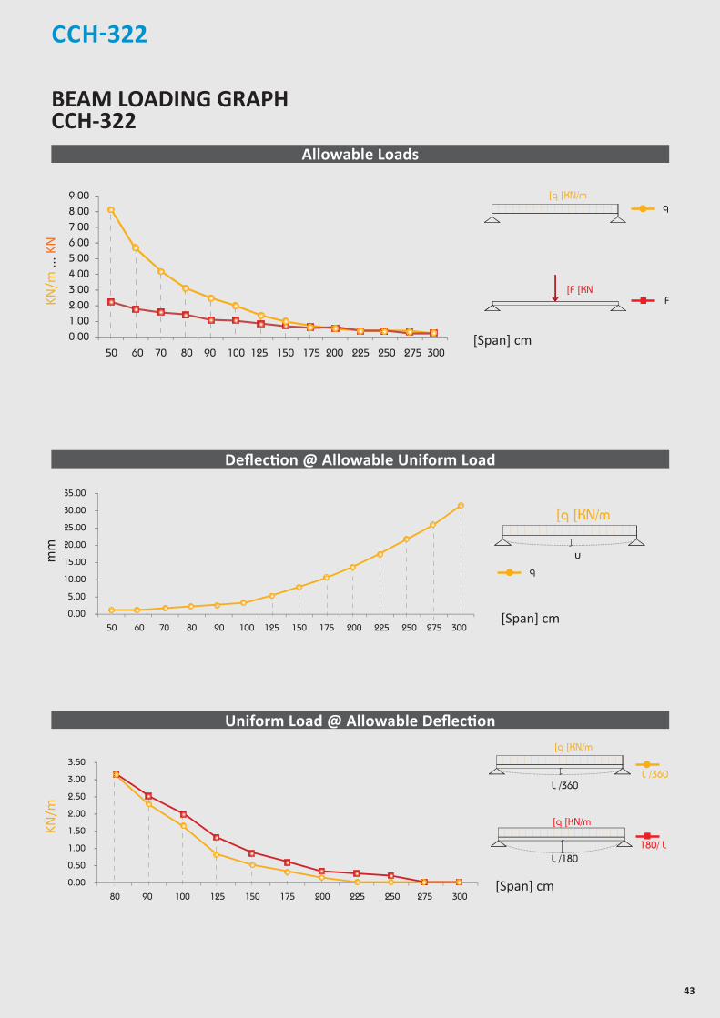
43
CCH-322
6.007.008.009.00
0.001.002.003.004.005.00
50 60 70 80 90 100 125 150 175 200 225 250 275 300
25.00
30.00
35.00
0.00
5.00
10.00
15.00
20.00
50 60 70 80 90 100 125 150 175 200 225 250 275 300
2.50
3.00
3.50
0.00
0.50
1.00
1.50
2.00
80 90 100 125 150 175 200 225 250 275 300
[Span] cm
[Span] cm
BEAM LOADING GRAPH CCH-322
Allowable Loads
Deflection @ Allowable Uniform Load
Uniform Load @ Allowable Deflection
[Span] cm
mm
Chosen Material:Allowable Bending Stress 21,82 kN/cm²Allowable Shear Stress 12,60 kN/cm²Modulus of Elasticity 21.000 kN/cm²
40B = S 235 JRG2
C-Channel:Area of Shear (Az)
1,67 cm
Moment of Inertia (Iy)
5,87 cm
Moment of Inertia (Iz
y
z
)
8,76 cm
min. Section Modulus (Sy)
2,72 cm
Warping Constant (Iw)
171,52 cm
Torsional Constant (IT)
0,07 cm
Plastic Moment cap. (Mpl,y)
0,82 kNm
Self weight (G)
2,32 kg/m
C 41x41x2,52
4
4
3
6
4
cmcmcmcmcmcmkNmkg/m
2
4
4
3
6
4
C-Channel:Cross Section Area (A) cm2
Moment of Inertia (I ) cm4
4Moment of Inertia (I ) cmSelf Weight (G) kg/m
^
Chosen Material:Allowable Bending Stress 21,82 kN/cm²Allowable Shear Stress 12,60 kN/cm²Modulus of Elasticity 21.000 kN/cm²
40B = S 235 JRG2
C-Channel:Area of Shear (Az)
1,67 cm
Moment of Inertia (Iy)
5,87 cm
Moment of Inertia (Iz
y
z
)
8,76 cm
min. Section Modulus (Sy)
2,72 cm
Warping Constant (Iw)
171,52 cm
Torsional Constant (IT)
0,07 cm
Plastic Moment cap. (Mpl,y)
0,82 kNm
Self weight (G)
2,32 kg/m
C 41x41x2,52
4
4
3
6
4
cmcmcmcmcmcmkNmkg/m
2
4
4
3
6
4
C-Channel:Cross Section Area (A) cm2
Moment of Inertia (I ) cm4
4Moment of Inertia (I ) cmSelf Weight (G) kg/m
^
F
]q ]KN/m
]F ]KN
q
180/ L
Chosen Material:Allowable Bending Stress 21,82 kN/cm²Allowable Shear Stress 12,60 kN/cm²Modulus of Elasticity 21.000 kN/cm²
40B = S 235 JRG2
C-Channel:Area of Shear (Az)
1,67 cm
Moment of Inertia (Iy)
5,87 cm
Moment of Inertia (Iz
y
z
)
8,76 cm
min. Section Modulus (Sy)
2,72 cm
Warping Constant (Iw)
171,52 cm
Torsional Constant (IT)
0,07 cm
Plastic Moment cap. (Mpl,y)
0,82 kNm
Self weight (G)
2,32 kg/m
C 41x41x2,52
4
4
3
6
4
cmcmcmcmcmcmkNmkg/m
2
4
4
3
6
4
C-Channel:Cross Section Area (A) cm2
Moment of Inertia (I ) cm4
4Moment of Inertia (I ) cmSelf Weight (G) kg/m
^
L /360
Chosen Material:Allowable Bending Stress 21,82 kN/cm²Allowable Shear Stress 12,60 kN/cm²Modulus of Elasticity 21.000 kN/cm²
40B = S 235 JRG2
C-Channel:Area of Shear (Az)
1,67 cm
Moment of Inertia (Iy)
5,87 cm
Moment of Inertia (Iz
y
z
)
8,76 cm
min. Section Modulus (Sy)
2,72 cm
Warping Constant (Iw)
171,52 cm
Torsional Constant (IT)
0,07 cm
Plastic Moment cap. (Mpl,y)
0,82 kNm
Self weight (G)
2,32 kg/m
C 41x41x2,52
4
4
3
6
4
cmcmcmcmcmcmkNmkg/m
2
4
4
3
6
4
C-Channel:Cross Section Area (A) cm2
Moment of Inertia (I ) cm4
4Moment of Inertia (I ) cmSelf Weight (G) kg/m
^
L /180
]q ]KN/m
L /360
]q ]KN/m
Chosen Material:Allowable Bending Stress 21,82 kN/cm²Allowable Shear Stress 12,60 kN/cm²Modulus of Elasticity 21.000 kN/cm²
40B = S 235 JRG2
C-Channel:Area of Shear (Az)
1,67 cm
Moment of Inertia (Iy)
5,87 cm
Moment of Inertia (Iz
y
z
)
8,76 cm
min. Section Modulus (Sy)
2,72 cm
Warping Constant (Iw)
171,52 cm
Torsional Constant (IT)
0,07 cm
Plastic Moment cap. (Mpl,y)
0,82 kNm
Self weight (G)
2,32 kg/m
C 41x41x2,52
4
4
3
6
4
cmcmcmcmcmcmkNmkg/m
2
4
4
3
6
4
C-Channel:Cross Section Area (A) cm2
Moment of Inertia (I ) cm4
4Moment of Inertia (I ) cmSelf Weight (G) kg/m
^
u
]q ]KN/m
q
KN/m
... K
NKN
/m

44
CCH-322
allowable uniform Load
ACase:
Length
B C D
Leng
th
C-Channel: 41 x 21 x 2.0 b2b
Cross Section Area (A) 3.67 cm2
Moment of Inertia (Iy) 21.11 cm4
Moment of Inertia (Iz) 11.37 cm4
Self weight (G) 2.88 kg/m
Span (L) Allowable Central Load** [KN]
[cm] Case A Case B Case C Case D
50 24.00 24.00 24.00 24.00
60 24.00 24.00 24.00 24.00
70 24.00 24.00 24.00 24.00
80 24.00 24.00 24.00 24.00
90 24.00 24.00 24.00 23.00
100 24.00 24.00 24.00 20.00
125 24.00 24.00 24.00 14.00
150 24.00 24.00 24.00 10.00
175 24.00 24.00 24.00 8.00
200 20.00 24.00 24.00 6.00
225 17.00 24.00 24.00 5.00
250 14.00 24.00 24.00 4.40
275 12.00 21.00 24.00 3.70
300 10.00 19.00 24.00 x
** Given loads are always “allowable characteristic live load”
15.00
20.00
25.00
0.00
5.00
10.00
50 60 70 80 90 100 125 150 175 200 225 250 275 300
KN
[Length]cm
Case A
Case B
Case CCase D
CCH-322
Column Load Data
Z
Z
YY
Z
Z
YY
Z
Z
YY
Z
Z
Y Y
21.0
7.0
41.0
21.0
41.0
22.0
42.0
7.0
41.0
22.0
41.0
7.0
41.0
41.0
41.0
22.0
82.0
7.0
41.0
22.0
50
30
13
Load table for single beam with uniform (characteristic) Live-LoadThis associated data are considered for perforated and non-perforated c-channel types according to DIN 18.800
Allowable Central Load**
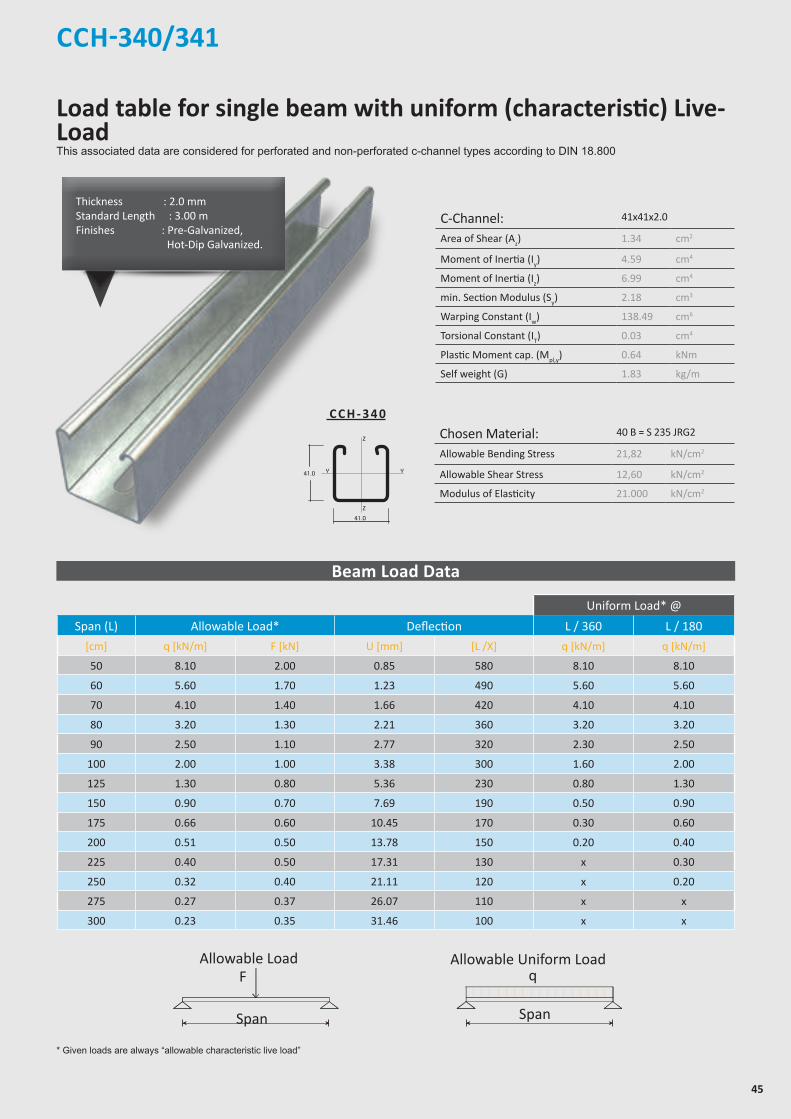
45
CCH-340/341
Z
Z
YY
Z
Z
YY
Z
Z
YY
Z
Z
Y Y
21.0
7.0
41.0
21.0
41.0
22.0
42.0
7.0
41.0
22.0
41.0
7.0
41.0
41.0
41.0
22.0
82.0
7.0
41.0
22.0
50
30
13
* Given loads are always “allowable characteristic live load”
Beam Load Data
C-Channel: 41x41x2.0
Area of Shear (Az) 1.34 cm2
Moment of Inertia (Iy) 4.59 cm4
Moment of Inertia (Iz) 6.99 cm4
min. Section Modulus (Sy) 2.18 cm3
Warping Constant (Iw) 138.49 cm6
Torsional Constant (IT) 0.03 cm4
Plastic Moment cap. (Mpl,y) 0.64 kNm
Self weight (G) 1.83 kg/m
Chosen Material: 40 B = S 235 JRG2
Allowable Bending Stress 21,82 kN/cm2
Allowable Shear Stress 12,60 kN/cm2
Modulus of Elasticity 21.000 kN/cm2
C C H - 3 4 0
Uniform Load* @
Span (L) Allowable Load* Deflection L / 360 L / 180
[cm] q [kN/m] F [kN] U [mm] [L /X] q [kN/m] q [kN/m]
50 8.10 2.00 0.85 580 8.10 8.10
60 5.60 1.70 1.23 490 5.60 5.60
70 4.10 1.40 1.66 420 4.10 4.10
80 3.20 1.30 2.21 360 3.20 3.20
90 2.50 1.10 2.77 320 2.30 2.50
100 2.00 1.00 3.38 300 1.60 2.00
125 1.30 0.80 5.36 230 0.80 1.30
150 0.90 0.70 7.69 190 0.50 0.90
175 0.66 0.60 10.45 170 0.30 0.60
200 0.51 0.50 13.78 150 0.20 0.40
225 0.40 0.50 17.31 130 x 0.30
250 0.32 0.40 21.11 120 x 0.20
275 0.27 0.37 26.07 110 x x
300 0.23 0.35 31.46 100 x x
Chosen Material:Allowable Bending Stress 21,82 kN/cm²Allowable Shear Stress 12,60 kN/cm²Modulus of Elasticity 21.000 kN/cm²
40B = S 235 JRG2
C-Channel:Area of Shear (Az)
1,67 cm
Moment of Inertia (Iy)
5,87 cm
Moment of Inertia (Iz
y
z
)
8,76 cm
min. Section Modulus (Sy)
2,72 cm
Warping Constant (Iw)
171,52 cm
Torsional Constant (IT)
0,07 cm
Plastic Moment cap. (Mpl,y)
0,82 kNm
Self weight (G)
2,32 kg/m
C 41x41x2,52
4
4
3
6
4
cmcmcmcmcmcmkNmkg/m
2
4
4
3
6
4
C-Channel:Cross Section Area (A) cm2
Moment of Inertia (I ) cm4
4Moment of Inertia (I ) cmSelf Weight (G) kg/m
^
Allowable Load
Span
F
Chosen Material:Allowable Bending Stress 21,82 kN/cm²Allowable Shear Stress 12,60 kN/cm²Modulus of Elasticity 21.000 kN/cm²
40B = S 235 JRG2
C-Channel:Area of Shear (Az)
1,67 cm
Moment of Inertia (Iy)
5,87 cm
Moment of Inertia (Iz
y
z
)
8,76 cm
min. Section Modulus (Sy)
2,72 cm
Warping Constant (Iw)
171,52 cm
Torsional Constant (IT)
0,07 cm
Plastic Moment cap. (Mpl,y)
0,82 kNm
Self weight (G)
2,32 kg/m
C 41x41x2,52
4
4
3
6
4
cmcmcmcmcmcmkNmkg/m
2
4
4
3
6
4
C-Channel:Cross Section Area (A) cm2
Moment of Inertia (I ) cm4
4Moment of Inertia (I ) cmSelf Weight (G) kg/m
^
Allowable Uniform Load
Span
q
Thickness : 2.0 mmStandard Length : 3.00 m Finishes : Pre-Galvanized, Hot-Dip Galvanized.
Load table for single beam with uniform (characteristic) Live-LoadThis associated data are considered for perforated and non-perforated c-channel types according to DIN 18.800
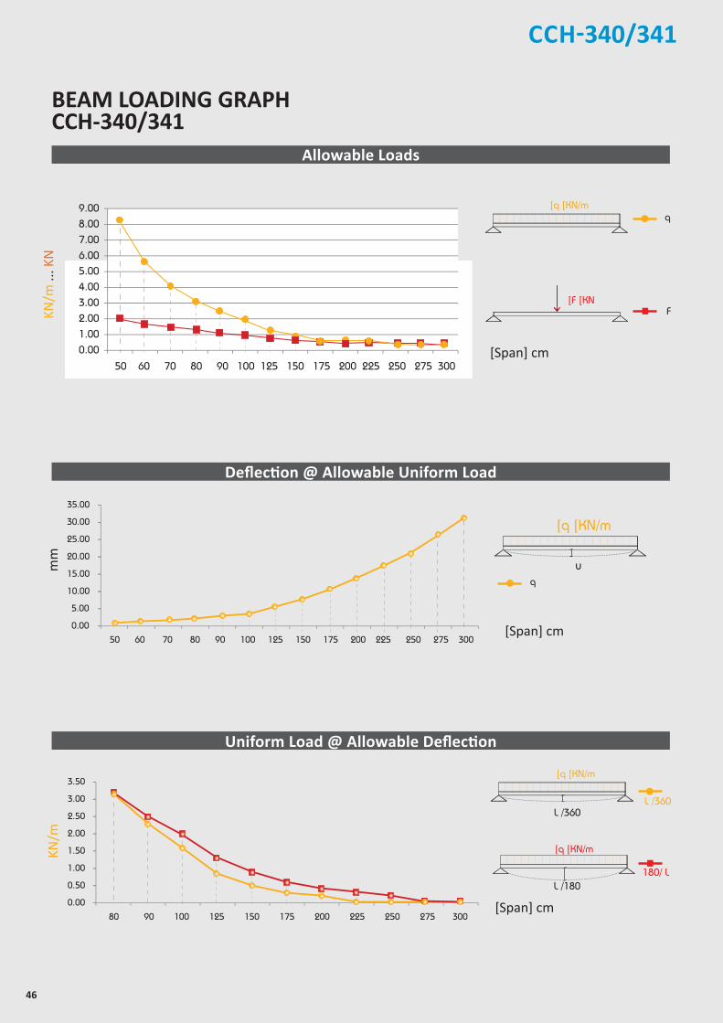
46
CCH-340/341
6.007.008.009.00
0.001.002.003.004.005.00
50 60 70 80 90 100 125 150 175 200 225 250 275 300
25.00
30.00
35.00
0.00
5.00
10.00
15.00
20.00
50 60 70 80 90 100 125 150 175 200 225 250 275 300
2.50
3.00
3.50
0.00
0.50
1.00
1.50
2.00
80 90 100 125 150 175 200 225 250 275 300
[Span] cm
BEAM LOADING GRAPH CCH-340/341
[Span] cm
Allowable Loads
Deflection @ Allowable Uniform Load
Uniform Load @ Allowable Deflection
[Span] cm
mm
Chosen Material:Allowable Bending Stress 21,82 kN/cm²Allowable Shear Stress 12,60 kN/cm²Modulus of Elasticity 21.000 kN/cm²
40B = S 235 JRG2
C-Channel:Area of Shear (Az)
1,67 cm
Moment of Inertia (Iy)
5,87 cm
Moment of Inertia (Iz
y
z
)
8,76 cm
min. Section Modulus (Sy)
2,72 cm
Warping Constant (Iw)
171,52 cm
Torsional Constant (IT)
0,07 cm
Plastic Moment cap. (Mpl,y)
0,82 kNm
Self weight (G)
2,32 kg/m
C 41x41x2,52
4
4
3
6
4
cmcmcmcmcmcmkNmkg/m
2
4
4
3
6
4
C-Channel:Cross Section Area (A) cm2
Moment of Inertia (I ) cm4
4Moment of Inertia (I ) cmSelf Weight (G) kg/m
^
Chosen Material:Allowable Bending Stress 21,82 kN/cm²Allowable Shear Stress 12,60 kN/cm²Modulus of Elasticity 21.000 kN/cm²
40B = S 235 JRG2
C-Channel:Area of Shear (Az)
1,67 cm
Moment of Inertia (Iy)
5,87 cm
Moment of Inertia (Iz
y
z
)
8,76 cm
min. Section Modulus (Sy)
2,72 cm
Warping Constant (Iw)
171,52 cm
Torsional Constant (IT)
0,07 cm
Plastic Moment cap. (Mpl,y)
0,82 kNm
Self weight (G)
2,32 kg/m
C 41x41x2,52
4
4
3
6
4
cmcmcmcmcmcmkNmkg/m
2
4
4
3
6
4
C-Channel:Cross Section Area (A) cm2
Moment of Inertia (I ) cm4
4Moment of Inertia (I ) cmSelf Weight (G) kg/m
^
F
]q ]KN/m
]F ]KN
q
180/ L
Chosen Material:Allowable Bending Stress 21,82 kN/cm²Allowable Shear Stress 12,60 kN/cm²Modulus of Elasticity 21.000 kN/cm²
40B = S 235 JRG2
C-Channel:Area of Shear (Az)
1,67 cm
Moment of Inertia (Iy)
5,87 cm
Moment of Inertia (Iz
y
z
)
8,76 cm
min. Section Modulus (Sy)
2,72 cm
Warping Constant (Iw)
171,52 cm
Torsional Constant (IT)
0,07 cm
Plastic Moment cap. (Mpl,y)
0,82 kNm
Self weight (G)
2,32 kg/m
C 41x41x2,52
4
4
3
6
4
cmcmcmcmcmcmkNmkg/m
2
4
4
3
6
4
C-Channel:Cross Section Area (A) cm2
Moment of Inertia (I ) cm4
4Moment of Inertia (I ) cmSelf Weight (G) kg/m
^
L /360
Chosen Material:Allowable Bending Stress 21,82 kN/cm²Allowable Shear Stress 12,60 kN/cm²Modulus of Elasticity 21.000 kN/cm²
40B = S 235 JRG2
C-Channel:Area of Shear (Az)
1,67 cm
Moment of Inertia (Iy)
5,87 cm
Moment of Inertia (Iz
y
z
)
8,76 cm
min. Section Modulus (Sy)
2,72 cm
Warping Constant (Iw)
171,52 cm
Torsional Constant (IT)
0,07 cm
Plastic Moment cap. (Mpl,y)
0,82 kNm
Self weight (G)
2,32 kg/m
C 41x41x2,52
4
4
3
6
4
cmcmcmcmcmcmkNmkg/m
2
4
4
3
6
4
C-Channel:Cross Section Area (A) cm2
Moment of Inertia (I ) cm4
4Moment of Inertia (I ) cmSelf Weight (G) kg/m
^
L /180
]q ]KN/m
L /360
]q ]KN/m
Chosen Material:Allowable Bending Stress 21,82 kN/cm²Allowable Shear Stress 12,60 kN/cm²Modulus of Elasticity 21.000 kN/cm²
40B = S 235 JRG2
C-Channel:Area of Shear (Az)
1,67 cm
Moment of Inertia (Iy)
5,87 cm
Moment of Inertia (Iz
y
z
)
8,76 cm
min. Section Modulus (Sy)
2,72 cm
Warping Constant (Iw)
171,52 cm
Torsional Constant (IT)
0,07 cm
Plastic Moment cap. (Mpl,y)
0,82 kNm
Self weight (G)
2,32 kg/m
C 41x41x2,52
4
4
3
6
4
cmcmcmcmcmcmkNmkg/m
2
4
4
3
6
4
C-Channel:Cross Section Area (A) cm2
Moment of Inertia (I ) cm4
4Moment of Inertia (I ) cmSelf Weight (G) kg/m
^
u
]q ]KN/m
q
KN/m
KN/m
... K
N
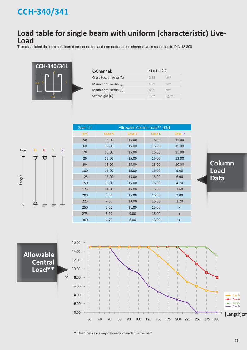
47
CCH-340/341
** Given loads are always “allowable characteristic live load”
allowable uniform Load
ACase:
Length
B C D
Leng
th
C-Channel: 41 x 41 x 2.0
Cross Section Area (A) 2.33 cm2
Moment of Inertia (Iy) 4.59 cm4
Moment of Inertia (Iz) 6.99 cm4
Self weight (G) 1.83 kg/m
Span (L) Allowable Central Load** [KN]
[cm] Case A Case B Case C Case D
50 15.00 15.00 15.00 15.00
60 15.00 15.00 15.00 15.00
70 15.00 15.00 15.00 15.00
80 15.00 15.00 15.00 12.00
90 15.00 15.00 15.00 10.00
100 15.00 15.00 15.00 9.00
125 15.00 15.00 15.00 6.00
150 13.00 15.00 15.00 4.70
175 11.00 15.00 15.00 3.60
200 9.00 15.00 15.00 2.80
225 7.00 13.00 15.00 2.20
250 6.00 11.00 15.00 x
275 5.00 9.00 15.00 x
300 4.70 8.00 13.00 x
10.00
12.00
14.00
16.00
0.00
2.00
4.00
6.00
8.00
50 60 70 80 90 100 125 150 175 200 225 250 275 300
KN
[Length]cm
Case A
Case B
Case CCase D
Allowable Central Load**
Column Load Data
Z
Z
YY
Z
Z
YY
Z
Z
YY
Z
Z
Y Y
21.0
7.0
41.0
21.0
41.0
22.0
42.0
7.0
41.0
22.0
41.0
7.0
41.0
41.0
41.0
22.0
82.0
7.0
41.0
22.0
50
30
13
Load table for single beam with uniform (characteristic) Live-LoadThis associated data are considered for perforated and non-perforated c-channel types according to DIN 18.800
CCH-340/341

48
C-Channel: 41x41x2.0 b2b
Area of Shear (Az) 1.88 cm2
Moment of Inertia (Iy) 26.81 cm4
Moment of Inertia (Iz) 14.04 cm4
min. Section Modulus (Sy) 6.62 cm3
Warping Constant (Iw) 113.65 cm6
Torsional Constant (IT) 0.08 cm4
Plastic Moment cap. (Mpl,y) 1.98 kNm
Self weight (G) 3.76 kg/m
Chosen Material: 40 B = S 235 JRG2
Allowable Bending Stress 21,82 kN/cm2
Allowable Shear Stress 12,60 kN/cm2
Modulus of Elasticity 21.000 kN/cm2
CCH-342
C C H - 3 4 2
Z
Z
YY
Z
Z
YY
Z
Z
YY
Z
Z
Y Y
21.0
7.0
41.0
21.0
41.0
22.0
42.0
7.0
41.0
22.0
41.0
7.0
41.0
41.0
41.0
22.0
82.0
7.0
41.0
22.0
50
30
13
* Given loads are always “allowable characteristic live load”
Beam Load Data
Uniform Load* @
Span (L) Allowable Load* Deflection L / 360 L / 180
[cm] q [kN/m] F [kN] U [mm] [L /X] q [kN/m] q [kN/m]
50 24.70 6.20 0.45 1.120 24.70 24.70
60 17.10 5.10 0.64 940 17.10 17.10
70 12.60 4.40 0.87 800 12.60 12.60
80 9.60 3.80 1.14 700 9.60 9.60
90 7.60 3.40 1.44 620 7.60 7.60
100 6.20 3.10 1.79 560 6.20 6.20
125 3.90 2.40 2.75 450 3.90 3.90
150 2.70 2.00 3.9 380 2.70 2.70
175 2.00 1.80 5.42 320 1.80 2.00
200 1.50 1.50 6.4 290 1.20 1.50
225 1.10 1.20 8.15 280 0.80 1.10
250 0.90 1.10 10.16 250 0.60 0.90
275 0.66 0.90 10.91 250 0.50 0.70
300 0.52 0.80 12.18 250 0.40 0.50
Chosen Material:Allowable Bending Stress 21,82 kN/cm²Allowable Shear Stress 12,60 kN/cm²Modulus of Elasticity 21.000 kN/cm²
40B = S 235 JRG2
C-Channel:Area of Shear (Az)
1,67 cm
Moment of Inertia (Iy)
5,87 cm
Moment of Inertia (Iz
y
z
)
8,76 cm
min. Section Modulus (Sy)
2,72 cm
Warping Constant (Iw)
171,52 cm
Torsional Constant (IT)
0,07 cm
Plastic Moment cap. (Mpl,y)
0,82 kNm
Self weight (G)
2,32 kg/m
C 41x41x2,52
4
4
3
6
4
cmcmcmcmcmcmkNmkg/m
2
4
4
3
6
4
C-Channel:Cross Section Area (A) cm2
Moment of Inertia (I ) cm4
4Moment of Inertia (I ) cmSelf Weight (G) kg/m
^
Allowable Load
Span
F
Chosen Material:Allowable Bending Stress 21,82 kN/cm²Allowable Shear Stress 12,60 kN/cm²Modulus of Elasticity 21.000 kN/cm²
40B = S 235 JRG2
C-Channel:Area of Shear (Az)
1,67 cm
Moment of Inertia (Iy)
5,87 cm
Moment of Inertia (Iz
y
z
)
8,76 cm
min. Section Modulus (Sy)
2,72 cm
Warping Constant (Iw)
171,52 cm
Torsional Constant (IT)
0,07 cm
Plastic Moment cap. (Mpl,y)
0,82 kNm
Self weight (G)
2,32 kg/m
C 41x41x2,52
4
4
3
6
4
cmcmcmcmcmcmkNmkg/m
2
4
4
3
6
4
C-Channel:Cross Section Area (A) cm2
Moment of Inertia (I ) cm4
4Moment of Inertia (I ) cmSelf Weight (G) kg/m
^
Allowable Uniform Load
Span
q
Thickness : 2.0 mmStandard Length : 3.00 m Finishes : Pre-Galvanized, Hot-Dip Galvanized.
Load table for single beam with uniform (characteristic) Live-LoadThis associated data are considered for perforated and non-perforated c-channel types according to DIN 18.800
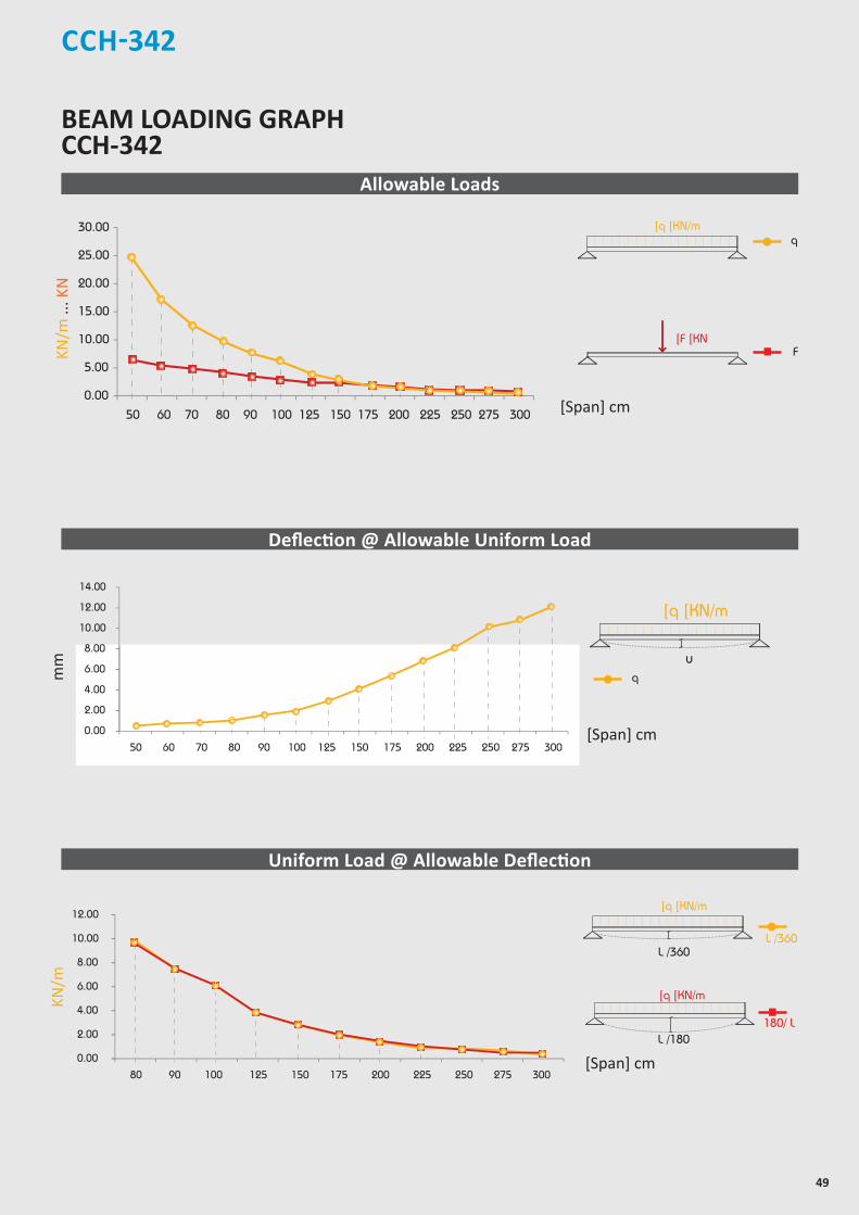
49
CCH-342
20.00
25.00
30.00
0.00
5.00
10.00
15.00
50 60 70 80 90 100 125 150 175 200 225 250 275 300
10.00
12.00
14.00
0.00
2.00
4.00
6.00
8.00
50 60 70 80 90 100 125 150 175 200 225 250 275 300
8.00
10.00
12.00
0.00
2.00
4.00
6.00
80 90 100 125 150 175 200 225 250 275 300
[Span] cm
[Span] cm
BEAM LOADING GRAPH CCH-342
Allowable Loads
Deflection @ Allowable Uniform Load
Uniform Load @ Allowable Deflection
[Span] cm
mm
Chosen Material:Allowable Bending Stress 21,82 kN/cm²Allowable Shear Stress 12,60 kN/cm²Modulus of Elasticity 21.000 kN/cm²
40B = S 235 JRG2
C-Channel:Area of Shear (Az)
1,67 cm
Moment of Inertia (Iy)
5,87 cm
Moment of Inertia (Iz
y
z
)
8,76 cm
min. Section Modulus (Sy)
2,72 cm
Warping Constant (Iw)
171,52 cm
Torsional Constant (IT)
0,07 cm
Plastic Moment cap. (Mpl,y)
0,82 kNm
Self weight (G)
2,32 kg/m
C 41x41x2,52
4
4
3
6
4
cmcmcmcmcmcmkNmkg/m
2
4
4
3
6
4
C-Channel:Cross Section Area (A) cm2
Moment of Inertia (I ) cm4
4Moment of Inertia (I ) cmSelf Weight (G) kg/m
^
Chosen Material:Allowable Bending Stress 21,82 kN/cm²Allowable Shear Stress 12,60 kN/cm²Modulus of Elasticity 21.000 kN/cm²
40B = S 235 JRG2
C-Channel:Area of Shear (Az)
1,67 cm
Moment of Inertia (Iy)
5,87 cm
Moment of Inertia (Iz
y
z
)
8,76 cm
min. Section Modulus (Sy)
2,72 cm
Warping Constant (Iw)
171,52 cm
Torsional Constant (IT)
0,07 cm
Plastic Moment cap. (Mpl,y)
0,82 kNm
Self weight (G)
2,32 kg/m
C 41x41x2,52
4
4
3
6
4
cmcmcmcmcmcmkNmkg/m
2
4
4
3
6
4
C-Channel:Cross Section Area (A) cm2
Moment of Inertia (I ) cm4
4Moment of Inertia (I ) cmSelf Weight (G) kg/m
^
F
]q ]KN/m
]F ]KN
q
180/ L
Chosen Material:Allowable Bending Stress 21,82 kN/cm²Allowable Shear Stress 12,60 kN/cm²Modulus of Elasticity 21.000 kN/cm²
40B = S 235 JRG2
C-Channel:Area of Shear (Az)
1,67 cm
Moment of Inertia (Iy)
5,87 cm
Moment of Inertia (Iz
y
z
)
8,76 cm
min. Section Modulus (Sy)
2,72 cm
Warping Constant (Iw)
171,52 cm
Torsional Constant (IT)
0,07 cm
Plastic Moment cap. (Mpl,y)
0,82 kNm
Self weight (G)
2,32 kg/m
C 41x41x2,52
4
4
3
6
4
cmcmcmcmcmcmkNmkg/m
2
4
4
3
6
4
C-Channel:Cross Section Area (A) cm2
Moment of Inertia (I ) cm4
4Moment of Inertia (I ) cmSelf Weight (G) kg/m
^
L /360
Chosen Material:Allowable Bending Stress 21,82 kN/cm²Allowable Shear Stress 12,60 kN/cm²Modulus of Elasticity 21.000 kN/cm²
40B = S 235 JRG2
C-Channel:Area of Shear (Az)
1,67 cm
Moment of Inertia (Iy)
5,87 cm
Moment of Inertia (Iz
y
z
)
8,76 cm
min. Section Modulus (Sy)
2,72 cm
Warping Constant (Iw)
171,52 cm
Torsional Constant (IT)
0,07 cm
Plastic Moment cap. (Mpl,y)
0,82 kNm
Self weight (G)
2,32 kg/m
C 41x41x2,52
4
4
3
6
4
cmcmcmcmcmcmkNmkg/m
2
4
4
3
6
4
C-Channel:Cross Section Area (A) cm2
Moment of Inertia (I ) cm4
4Moment of Inertia (I ) cmSelf Weight (G) kg/m
^
L /180
]q ]KN/m
L /360
]q ]KN/m
Chosen Material:Allowable Bending Stress 21,82 kN/cm²Allowable Shear Stress 12,60 kN/cm²Modulus of Elasticity 21.000 kN/cm²
40B = S 235 JRG2
C-Channel:Area of Shear (Az)
1,67 cm
Moment of Inertia (Iy)
5,87 cm
Moment of Inertia (Iz
y
z
)
8,76 cm
min. Section Modulus (Sy)
2,72 cm
Warping Constant (Iw)
171,52 cm
Torsional Constant (IT)
0,07 cm
Plastic Moment cap. (Mpl,y)
0,82 kNm
Self weight (G)
2,32 kg/m
C 41x41x2,52
4
4
3
6
4
cmcmcmcmcmcmkNmkg/m
2
4
4
3
6
4
C-Channel:Cross Section Area (A) cm2
Moment of Inertia (I ) cm4
4Moment of Inertia (I ) cmSelf Weight (G) kg/m
^
u
]q ]KN/m
q
KN/m
... K
NKN
/m
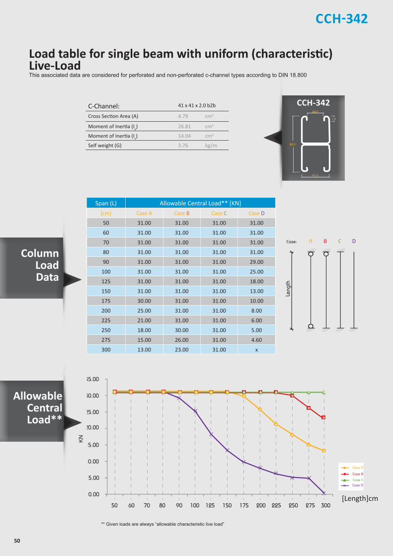
50
CCH-342
Column Load Data
CCH-342Z
Z
YY
Z
Z
YY
Z
Z
YY
Z
Z
Y Y
21.0
7.0
41.0
21.0
41.0
22.0
42.0
7.0
41.0
22.0
41.0
7.0
41.0
41.0
41.0
22.0
82.0
7.0
41.0
22.0
50
30
13
allowable uniform Load
ACase:
Length
B C D
Leng
th
C-Channel: 41 x 41 x 2.0 b2b
Cross Section Area (A) 4.79 cm2
Moment of Inertia (Iy) 26.81 cm4
Moment of Inertia (Iz) 14.04 cm4
Self weight (G) 3.76 kg/m
Span (L) Allowable Central Load** [KN]
[cm] Case A Case B Case C Case D
50 31.00 31.00 31.00 31.00
60 31.00 31.00 31.00 31.00
70 31.00 31.00 31.00 31.00
80 31.00 31.00 31.00 31.00
90 31.00 31.00 31.00 29.00
100 31.00 31.00 31.00 25.00
125 31.00 31.00 31.00 18.00
150 31.00 31.00 31.00 13.00
175 30.00 31.00 31.00 10.00
200 25.00 31.00 31.00 8.00
225 21.00 31.00 31.00 6.00
250 18.00 30.00 31.00 5.00
275 15.00 26.00 31.00 4.60
300 13.00 23.00 31.00 x
** Given loads are always “allowable characteristic live load”
25.00
20.00
30.00
35.00
0.00
5.00
10.00
15.00
50 60 70 80 90 100 125 150 175 200 225 250 275 300
KN
[Length]cm
Case A
Case B
Case CCase D
Load table for single beam with uniform (characteristic) Live-LoadThis associated data are considered for perforated and non-perforated c-channel types according to DIN 18.800
Allowable Central Load**
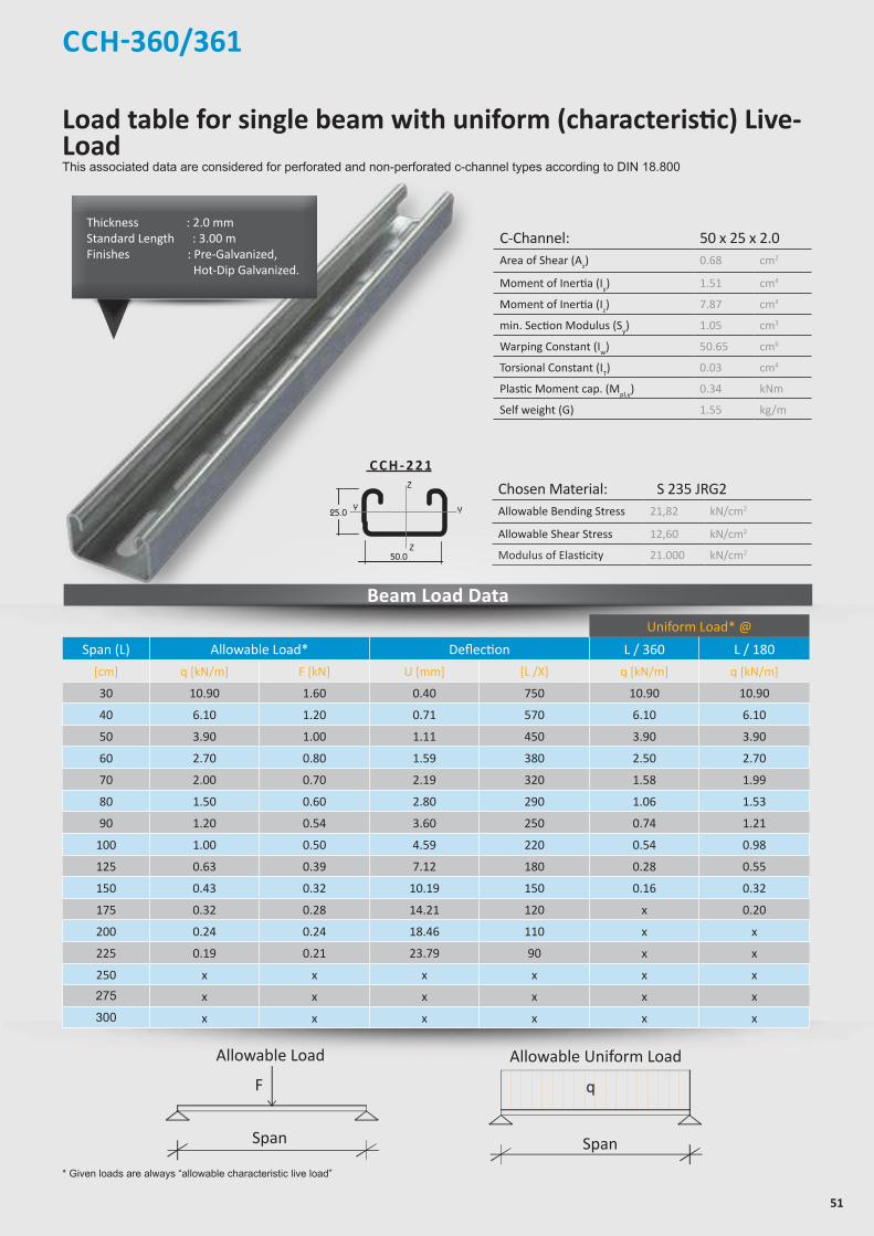
51
Load table for single beam with uniform (characteristic) Live-LoadThis associated data are considered for perforated and non-perforated c-channel types according to DIN 18.800
* Given loads are always “allowable characteristic live load”
Allowable Load
Span
F
Allowable Uniform Load
Span
q
C-Channel: 50 x 25 x 2.0Area of Shear (Az) 0.68 cm2
Moment of Inertia (Iy) 1.51 cm4
Moment of Inertia (Iz) 7.87 cm4
min. Section Modulus (Sy) 1.05 cm3
Warping Constant (Iw) 50.65 cm6
Torsional Constant (IT) 0.03 cm4
Plastic Moment cap. (Mpl,y) 0.34 kNm
Self weight (G) 1.55 kg/m
Chosen Material: S 235 JRG2Allowable Bending Stress 21,82 kN/cm2
Allowable Shear Stress 12,60 kN/cm2
Modulus of Elasticity 21.000 kN/cm2
Thickness : 2.0 mmStandard Length : 3.00 m Finishes : Pre-Galvanized, Hot-Dip Galvanized.
C C H - 2 2 1
Beam Load Data
CCH-360/361
Uniform Load* @
Span (L) Allowable Load* Deflection L / 360 L / 180
[cm] q [kN/m] F [kN] U [mm] [L /X] q [kN/m] q [kN/m]
30 10.90 1.60 0.40 750 10.90 10.90
40 6.10 1.20 0.71 570 6.10 6.10
50 3.90 1.00 1.11 450 3.90 3.90
60 2.70 0.80 1.59 380 2.50 2.70
70 2.00 0.70 2.19 320 1.58 1.99
80 1.50 0.60 2.80 290 1.06 1.53
90 1.20 0.54 3.60 250 0.74 1.21
100 1.00 0.50 4.59 220 0.54 0.98
125 0.63 0.39 7.12 180 0.28 0.55
150 0.43 0.32 10.19 150 0.16 0.32
175 0.32 0.28 14.21 120 x 0.20
200 0.24 0.24 18.46 110 x x
225 0.19 0.21 23.79 90 x x
250 x x x x x x
275 x x x x x x
300 x x x x x x
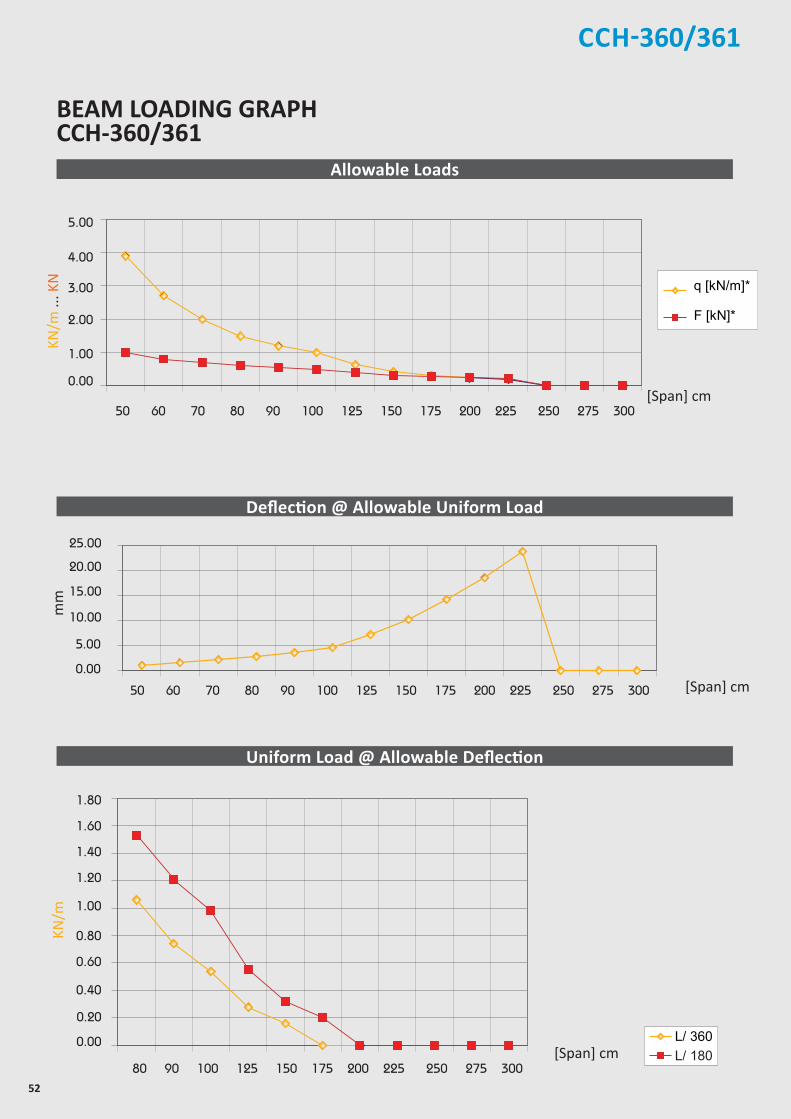
52
CCH-360/361
[Span] cm
BEAM LOADING GRAPH CCH-360/361
[Span] cm
Allowable Loads
Deflection @ Allowable Uniform Load
Uniform Load @ Allowable Deflection
[Span] cm
mm
KN/m
KN/m
... K
N

53
Load table for single beam with uniform (characteristic) Live-LoadThis associated data are considered for perforated and non-perforated c-channel types according to DIN 18.800
* Given loads are always “allowable characteristic live load”
Allowable Load
Span
F
Allowable Uniform Load
Span
q
C-Channel: 50 x 25 x 2.0 b2bArea of Shear (Az) 1.39 cm2
Moment of Inertia (Iy) 7.33 cm4
Moment of Inertia (Iz) 15.75 cm4
min. Section Modulus (Sy) 2.93 cm3
Warping Constant (Iw) 43.54 cm6
Torsional Constant (IT) 0.06 cm4
Plastic Moment cap. (Mpl,y) 0.88 kNm
Self weight (G) 3.00 kg/m
Chosen Material: S 235 JRG2Allowable Bending Stress 21,82 kN/cm2
Allowable Shear Stress 12,60 kN/cm2
Modulus of Elasticity 21.000 kN/cm2
Thickness : 2.0 mmStandard Length : 3.00 m Finishes : Pre-Galvanized, Hot-Dip Galvanized.
Beam Load Data
CCH-362
Uniform Load* @
Span (L) Allowable Load* Deflection L / 360 L / 180
[cm] q [kN/m] F [kN] U [mm] [L /X] q [kN/m] q [kN/m]
50 10,90 2,70 0,64 790 10,90 10,90
60 7,60 2,30 0,92 650 7,60 7,60
70 5,60 2,00 1,26 560 5,60 5,60
80 4,30 1,70 1,65 480 4,30 4,30
90 3,40 1,50 2,09 430 3,40 3,40
100 2,70 1,40 2,54 390 2,60 2,70
125 1,70 1,10 3,93 320 1,30 1,70
150 1,20 0,90 5,79 260 0,80 1,20
175 0,90 0,79 8,12 220 0,49 0,89
200 0,68 0,68 10,57 190 0,33 0,66
225 0,54 0,61 13,59 170 0,23 0,46
250 0,44 0,55 17,08 150 0,17 0,34
275 0,36 0,50 20,75 130 x 0,25
300 0,30 0,45 24,87 120 x 0,19
3 6 2
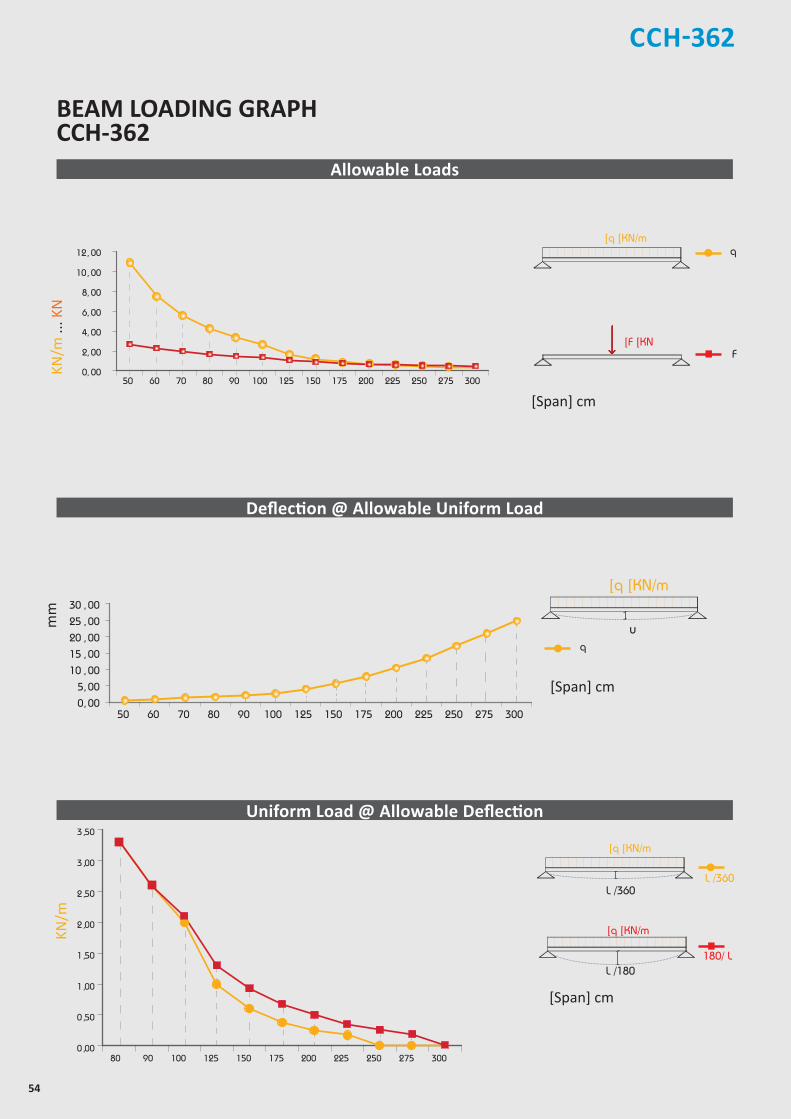
54
[Span] cm
Allowable Loads
Deflection @ Allowable Uniform Load
Uniform Load @ Allowable Deflection
[Span] cm
mm
[Span] cm
Chosen Material:Allowable Bending Stress 21,82 kN/cm²Allowable Shear Stress 12,60 kN/cm²Modulus of Elasticity 21.000 kN/cm²
40B = S 235 JRG2
C-Channel:Area of Shear (Az)
1,67 cm
Moment of Inertia (Iy)
5,87 cm
Moment of Inertia (Iz
y
z
)
8,76 cm
min. Section Modulus (Sy)
2,72 cm
Warping Constant (Iw)
171,52 cm
Torsional Constant (IT)
0,07 cm
Plastic Moment cap. (Mpl,y)
0,82 kNm
Self weight (G)
2,32 kg/m
C 41x41x2,52
4
4
3
6
4
cmcmcmcmcmcmkNmkg/m
2
4
4
3
6
4
C-Channel:Cross Section Area (A) cm2
Moment of Inertia (I ) cm4
4Moment of Inertia (I ) cmSelf Weight (G) kg/m
^
F
]q ]KN/m
]F ]KN
q
180/ L
Chosen Material:Allowable Bending Stress 21,82 kN/cm²Allowable Shear Stress 12,60 kN/cm²Modulus of Elasticity 21.000 kN/cm²
40B = S 235 JRG2
C-Channel:Area of Shear (Az)
1,67 cm
Moment of Inertia (Iy)
5,87 cm
Moment of Inertia (Iz
y
z
)
8,76 cm
min. Section Modulus (Sy)
2,72 cm
Warping Constant (Iw)
171,52 cm
Torsional Constant (IT)
0,07 cm
Plastic Moment cap. (Mpl,y)
0,82 kNm
Self weight (G)
2,32 kg/m
C 41x41x2,52
4
4
3
6
4
cmcmcmcmcmcmkNmkg/m
2
4
4
3
6
4
C-Channel:Cross Section Area (A) cm2
Moment of Inertia (I ) cm4
4Moment of Inertia (I ) cmSelf Weight (G) kg/m
^
L /360
Chosen Material:Allowable Bending Stress 21,82 kN/cm²Allowable Shear Stress 12,60 kN/cm²Modulus of Elasticity 21.000 kN/cm²
40B = S 235 JRG2
C-Channel:Area of Shear (Az)
1,67 cm
Moment of Inertia (Iy)
5,87 cm
Moment of Inertia (Iz
y
z
)
8,76 cm
min. Section Modulus (Sy)
2,72 cm
Warping Constant (Iw)
171,52 cm
Torsional Constant (IT)
0,07 cm
Plastic Moment cap. (Mpl,y)
0,82 kNm
Self weight (G)
2,32 kg/m
C 41x41x2,52
4
4
3
6
4
cmcmcmcmcmcmkNmkg/m
2
4
4
3
6
4
C-Channel:Cross Section Area (A) cm2
Moment of Inertia (I ) cm4
4Moment of Inertia (I ) cmSelf Weight (G) kg/m
^
L /180
]q ]KN/m
L /360
]q ]KN/m
Chosen Material:Allowable Bending Stress 21,82 kN/cm²Allowable Shear Stress 12,60 kN/cm²Modulus of Elasticity 21.000 kN/cm²
40B = S 235 JRG2
C-Channel:Area of Shear (Az)
1,67 cm
Moment of Inertia (Iy)
5,87 cm
Moment of Inertia (Iz
y
z
)
8,76 cm
min. Section Modulus (Sy)
2,72 cm
Warping Constant (Iw)
171,52 cm
Torsional Constant (IT)
0,07 cm
Plastic Moment cap. (Mpl,y)
0,82 kNm
Self weight (G)
2,32 kg/m
C 41x41x2,52
4
4
3
6
4
cmcmcmcmcmcmkNmkg/m
2
4
4
3
6
4
C-Channel:Cross Section Area (A) cm2
Moment of Inertia (I ) cm4
4Moment of Inertia (I ) cmSelf Weight (G) kg/m
^
u
]q ]KN/m
q
KN/m
BEAM LOADING GRAPHCCH-362
KN/m
... K
NCCH-362

55
CCH-420/421
Z
Z
YY
Z
Z
YY
Z
Z
YY
Z
Z
Y Y
21.0
7.0
41.0
21.0
41.0
22.0
42.0
7.0
41.0
22.0
41.0
7.0
41.0
41.0
41.0
22.0
82.0
7.0
41.0
22.0
50
30
13
* Given loads are always “allowable characteristic live load”
Beam Load Data
C-Channel: 41x21x2.5
Area of Shear (Az) 0.67 cm2
Moment of Inertia (Iy) 1.03 cm4
Moment of Inertia (Iz) 5.07 cm4
min. Section Modulus (Sy) 0.89 cm3
Warping Constant (Iw) 24.34 cm6
Torsional Constant (IT) 0.06 cm4
Plastic Moment cap. (Mpl,y) 0.29 kNm
Self weight (G) 1.56 kg/m
Chosen Material: 40 B = S 235 JRG2
Allowable Bending Stress 21,82 kN/cm2
Allowable Shear Stress 12,60 kN/cm2
Modulus of Elasticity 21.000 kN/cm2
C C H - 4 2 0
Uniform Load* @
Span (L) Allowable Load* Deflection L / 360 L / 180
[cm] q [kN/m] F [kN] U [mm] [L /X] q [kN/m] q [kN/m]
50 3.30 0.80 1.55 320 3.00 3.30
60 2.30 0.70 2.24 270 1.70 2.30
70 1.70 0.60 3.07 230 1.10 1.70
80 1.30 0.50 4.01 200 0.70 1.30
90 1.00 0.50 4.94 180 0.50 1.00
100 0.80 0.40 6.02 170 0.40 0.70
125 0.53 0.33 9.74 130 0.19 0.38
150 0.37 0.28 14.09 110 x 0.22
175 0.27 0.24 19.05 90 x x
200 0.21 0.21 25.28 80 x x
225 0.16 0.28 30.86 70 x x
250 x x x x x x
275 x x x x x x
300 x x x x x x
Chosen Material:Allowable Bending Stress 21,82 kN/cm²Allowable Shear Stress 12,60 kN/cm²Modulus of Elasticity 21.000 kN/cm²
40B = S 235 JRG2
C-Channel:Area of Shear (Az)
1,67 cm
Moment of Inertia (Iy)
5,87 cm
Moment of Inertia (Iz
y
z
)
8,76 cm
min. Section Modulus (Sy)
2,72 cm
Warping Constant (Iw)
171,52 cm
Torsional Constant (IT)
0,07 cm
Plastic Moment cap. (Mpl,y)
0,82 kNm
Self weight (G)
2,32 kg/m
C 41x41x2,52
4
4
3
6
4
cmcmcmcmcmcmkNmkg/m
2
4
4
3
6
4
C-Channel:Cross Section Area (A) cm2
Moment of Inertia (I ) cm4
4Moment of Inertia (I ) cmSelf Weight (G) kg/m
^
Allowable Load
Span
F
Chosen Material:Allowable Bending Stress 21,82 kN/cm²Allowable Shear Stress 12,60 kN/cm²Modulus of Elasticity 21.000 kN/cm²
40B = S 235 JRG2
C-Channel:Area of Shear (Az)
1,67 cm
Moment of Inertia (Iy)
5,87 cm
Moment of Inertia (Iz
y
z
)
8,76 cm
min. Section Modulus (Sy)
2,72 cm
Warping Constant (Iw)
171,52 cm
Torsional Constant (IT)
0,07 cm
Plastic Moment cap. (Mpl,y)
0,82 kNm
Self weight (G)
2,32 kg/m
C 41x41x2,52
4
4
3
6
4
cmcmcmcmcmcmkNmkg/m
2
4
4
3
6
4
C-Channel:Cross Section Area (A) cm2
Moment of Inertia (I ) cm4
4Moment of Inertia (I ) cmSelf Weight (G) kg/m
^
Allowable Uniform Load
Span
q
Thickness : 2.5 mmStandard Length : 3.00 m Finishes : Pre-Galvanized, Hot-Dip Galvanized.
Load table for single beam with uniform (characteristic) Live-LoadThis associated data are considered for perforated and non-perforated c-channel types according to DIN 18.800
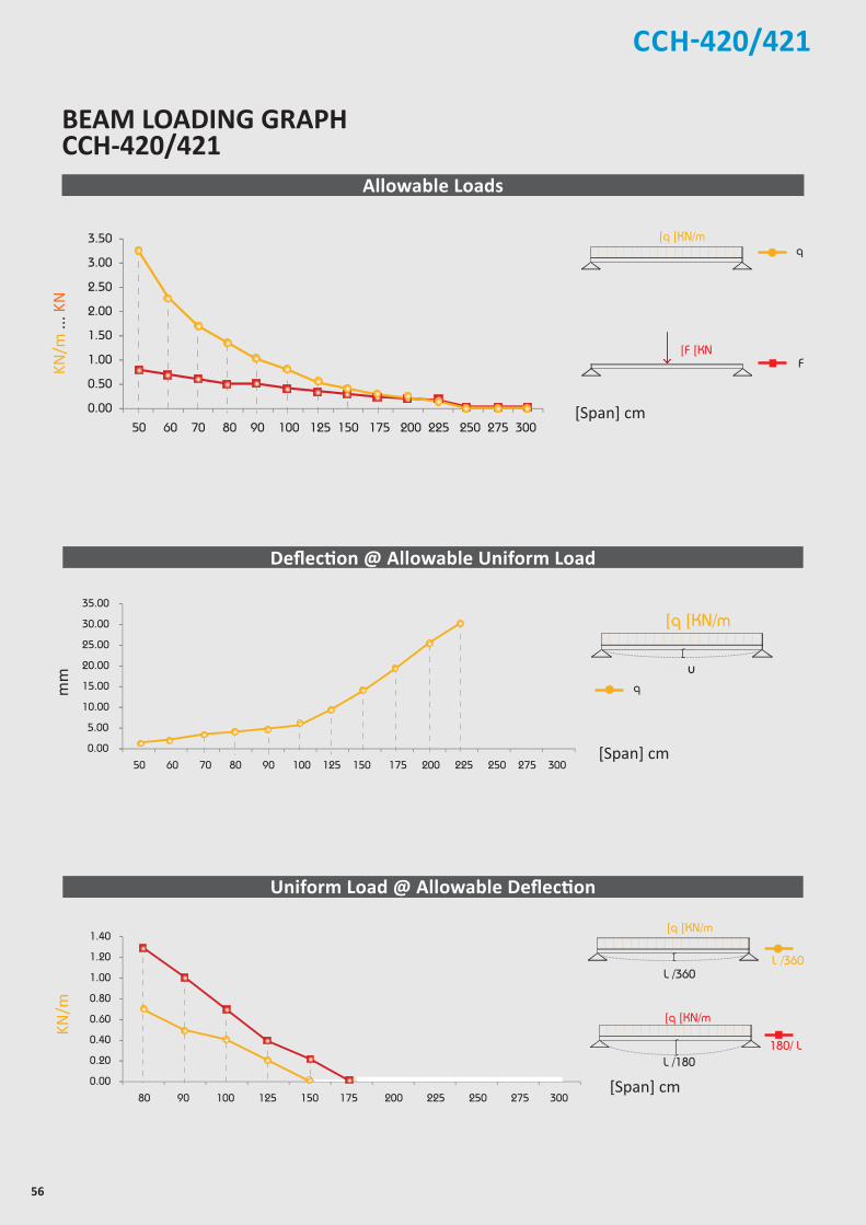
56
CCH-420/421
2.50
3.00
3.50
0.00
0.50
1.00
1.50
2.00
50 60 70 80 90 100 125 150 175 200 225 250 275 300
25.00
30.00
35.00
0.00
5.00
10.00
15.00
20.00
50 60 70 80 90 100 125 150 175 200 225 250 275 300
1.00
1.20
1.40
0.00
0.20
0.40
0.60
0.80
80 90 100 125 150 175 200 225 250 275 300
[Span] cm
BEAM LOADING GRAPH CCH-420/421
[Span] cm
Allowable Loads
Deflection @ Allowable Uniform Load
Uniform Load @ Allowable Deflection
[Span] cm
mm
Chosen Material:Allowable Bending Stress 21,82 kN/cm²Allowable Shear Stress 12,60 kN/cm²Modulus of Elasticity 21.000 kN/cm²
40B = S 235 JRG2
C-Channel:Area of Shear (Az)
1,67 cm
Moment of Inertia (Iy)
5,87 cm
Moment of Inertia (Iz
y
z
)
8,76 cm
min. Section Modulus (Sy)
2,72 cm
Warping Constant (Iw)
171,52 cm
Torsional Constant (IT)
0,07 cm
Plastic Moment cap. (Mpl,y)
0,82 kNm
Self weight (G)
2,32 kg/m
C 41x41x2,52
4
4
3
6
4
cmcmcmcmcmcmkNmkg/m
2
4
4
3
6
4
C-Channel:Cross Section Area (A) cm2
Moment of Inertia (I ) cm4
4Moment of Inertia (I ) cmSelf Weight (G) kg/m
^
F
]q ]KN/m
]F ]KN
q
180/ L
Chosen Material:Allowable Bending Stress 21,82 kN/cm²Allowable Shear Stress 12,60 kN/cm²Modulus of Elasticity 21.000 kN/cm²
40B = S 235 JRG2
C-Channel:Area of Shear (Az)
1,67 cm
Moment of Inertia (Iy)
5,87 cm
Moment of Inertia (Iz
y
z
)
8,76 cm
min. Section Modulus (Sy)
2,72 cm
Warping Constant (Iw)
171,52 cm
Torsional Constant (IT)
0,07 cm
Plastic Moment cap. (Mpl,y)
0,82 kNm
Self weight (G)
2,32 kg/m
C 41x41x2,52
4
4
3
6
4
cmcmcmcmcmcmkNmkg/m
2
4
4
3
6
4
C-Channel:Cross Section Area (A) cm2
Moment of Inertia (I ) cm4
4Moment of Inertia (I ) cmSelf Weight (G) kg/m
^
L /360
Chosen Material:Allowable Bending Stress 21,82 kN/cm²Allowable Shear Stress 12,60 kN/cm²Modulus of Elasticity 21.000 kN/cm²
40B = S 235 JRG2
C-Channel:Area of Shear (Az)
1,67 cm
Moment of Inertia (Iy)
5,87 cm
Moment of Inertia (Iz
y
z
)
8,76 cm
min. Section Modulus (Sy)
2,72 cm
Warping Constant (Iw)
171,52 cm
Torsional Constant (IT)
0,07 cm
Plastic Moment cap. (Mpl,y)
0,82 kNm
Self weight (G)
2,32 kg/m
C 41x41x2,52
4
4
3
6
4
cmcmcmcmcmcmkNmkg/m
2
4
4
3
6
4
C-Channel:Cross Section Area (A) cm2
Moment of Inertia (I ) cm4
4Moment of Inertia (I ) cmSelf Weight (G) kg/m
^
L /180
]q ]KN/m
L /360
]q ]KN/m
Chosen Material:Allowable Bending Stress 21,82 kN/cm²Allowable Shear Stress 12,60 kN/cm²Modulus of Elasticity 21.000 kN/cm²
40B = S 235 JRG2
C-Channel:Area of Shear (Az)
1,67 cm
Moment of Inertia (Iy)
5,87 cm
Moment of Inertia (Iz
y
z
)
8,76 cm
min. Section Modulus (Sy)
2,72 cm
Warping Constant (Iw)
171,52 cm
Torsional Constant (IT)
0,07 cm
Plastic Moment cap. (Mpl,y)
0,82 kNm
Self weight (G)
2,32 kg/m
C 41x41x2,52
4
4
3
6
4
cmcmcmcmcmcmkNmkg/m
2
4
4
3
6
4
C-Channel:Cross Section Area (A) cm2
Moment of Inertia (I ) cm4
4Moment of Inertia (I ) cmSelf Weight (G) kg/m
^
u
]q ]KN/m
q
KN/m
KN/m
... K
N
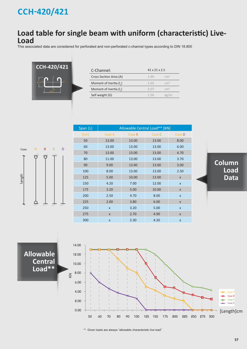
57
CCH-420/421
** Given loads are always “allowable characteristic live load”
allowable uniform Load
ACase:
Length
B C D
Leng
th
C-Channel: 41 x 21 x 2.5
Cross Section Area (A) 1.99 cm2
Moment of Inertia (Iy) 1.03 cm4
Moment of Inertia (Iz) 5.07 cm4
Self weight (G) 1.56 kg/m
Span (L) Allowable Central Load** [KN]
[cm] Case A Case B Case C Case D
50 13.00 13.00 13.00 8.00
60 13.00 13.00 13.00 6.00
70 13.00 13.00 13.00 4.70
80 11.00 13.00 13.00 3.70
90 9.00 13.00 13.00 3.00
100 8.00 13.00 13.00 2.50
125 5.00 10.00 13.00 x
150 4.20 7.00 12.00 x
175 3.20 5.00 10.00 x
200 2.50 4.70 8.00 x
225 2.00 3.80 6.00 x
250 x 3.20 5.00 x
275 x 2.70 4.90 x
300 x 2.30 4.20 x
10.00
8.00
12.00
14.00
0.00
2.00
4.00
6.00
50 60 70 80 90 100 125 150 175 200 225 250 275 300
KN
[Length]cm
Case A
Case B
Case CCase D
CCH-420/421
Allowable Central Load**
Column LoadData
Z
Z
YY
Z
Z
YY
Z
Z
YY
Z
Z
Y Y
21.0
7.0
41.0
21.0
41.0
22.0
42.0
7.0
41.0
22.0
41.0
7.0
41.0
41.0
41.0
22.0
82.0
7.0
41.0
22.0
50
30
13
Load table for single beam with uniform (characteristic) Live-LoadThis associated data are considered for perforated and non-perforated c-channel types according to DIN 18.800
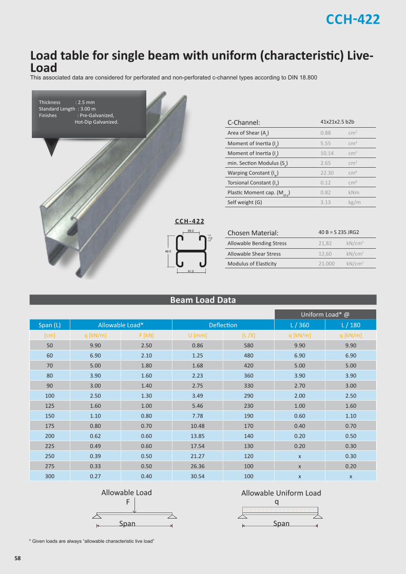
58
C-Channel: 41x21x2.5 b2b
Area of Shear (Az) 0.88 cm2
Moment of Inertia (Iy) 5.55 cm4
Moment of Inertia (Iz) 10.14 cm4
min. Section Modulus (Sy) 2.65 cm3
Warping Constant (Iw) 22.30 cm6
Torsional Constant (IT) 0.12 cm4
Plastic Moment cap. (Mpl,y) 0.82 kNm
Self weight (G) 3.13 kg/m
Chosen Material: 40 B = S 235 JRG2
Allowable Bending Stress 21,82 kN/cm2
Allowable Shear Stress 12,60 kN/cm2
Modulus of Elasticity 21.000 kN/cm2
CCH-422
Z
Z
YY
Z
Z
YY
Z
Z
YY
Z
Z
Y Y
21.0
7.0
41.0
21.0
41.0
22.0
42.0
7.0
41.0
22.0
41.0
7.0
41.0
41.0
41.0
22.0
82.0
7.0
41.0
22.0
50
30
13
C C H - 4 2 2
* Given loads are always “allowable characteristic live load”
Beam Load Data
Uniform Load* @
Span (L) Allowable Load* Deflection L / 360 L / 180
[cm] q [kN/m] F [kN] U [mm] [L /X] q [kN/m] q [kN/m]
50 9.90 2.50 0.86 580 9.90 9.90
60 6.90 2.10 1.25 480 6.90 6.90
70 5.00 1.80 1.68 420 5.00 5.00
80 3.90 1.60 2.23 360 3.90 3.90
90 3.00 1.40 2.75 330 2.70 3.00
100 2.50 1.30 3.49 290 2.00 2.50
125 1.60 1.00 5.46 230 1.00 1.60
150 1.10 0.80 7.78 190 0.60 1.10
175 0.80 0.70 10.48 170 0.40 0.70
200 0.62 0.60 13.85 140 0.20 0.50
225 0.49 0.60 17.54 130 0.20 0.30
250 0.39 0.50 21.27 120 x 0.30
275 0.33 0.50 26.36 100 x 0.20
300 0.27 0.40 30.54 100 x x
Chosen Material:Allowable Bending Stress 21,82 kN/cm²Allowable Shear Stress 12,60 kN/cm²Modulus of Elasticity 21.000 kN/cm²
40B = S 235 JRG2
C-Channel:Area of Shear (Az)
1,67 cm
Moment of Inertia (Iy)
5,87 cm
Moment of Inertia (Iz
y
z
)
8,76 cm
min. Section Modulus (Sy)
2,72 cm
Warping Constant (Iw)
171,52 cm
Torsional Constant (IT)
0,07 cm
Plastic Moment cap. (Mpl,y)
0,82 kNm
Self weight (G)
2,32 kg/m
C 41x41x2,52
4
4
3
6
4
cmcmcmcmcmcmkNmkg/m
2
4
4
3
6
4
C-Channel:Cross Section Area (A) cm2
Moment of Inertia (I ) cm4
4Moment of Inertia (I ) cmSelf Weight (G) kg/m
^
Allowable Load
Span
F
Chosen Material:Allowable Bending Stress 21,82 kN/cm²Allowable Shear Stress 12,60 kN/cm²Modulus of Elasticity 21.000 kN/cm²
40B = S 235 JRG2
C-Channel:Area of Shear (Az)
1,67 cm
Moment of Inertia (Iy)
5,87 cm
Moment of Inertia (Iz
y
z
)
8,76 cm
min. Section Modulus (Sy)
2,72 cm
Warping Constant (Iw)
171,52 cm
Torsional Constant (IT)
0,07 cm
Plastic Moment cap. (Mpl,y)
0,82 kNm
Self weight (G)
2,32 kg/m
C 41x41x2,52
4
4
3
6
4
cmcmcmcmcmcmkNmkg/m
2
4
4
3
6
4
C-Channel:Cross Section Area (A) cm2
Moment of Inertia (I ) cm4
4Moment of Inertia (I ) cmSelf Weight (G) kg/m
^
Allowable Uniform Load
Span
q
Thickness : 2.5 mmStandard Length : 3.00 m Finishes : Pre-Galvanized, Hot-Dip Galvanized.
Load table for single beam with uniform (characteristic) Live-LoadThis associated data are considered for perforated and non-perforated c-channel types according to DIN 18.800
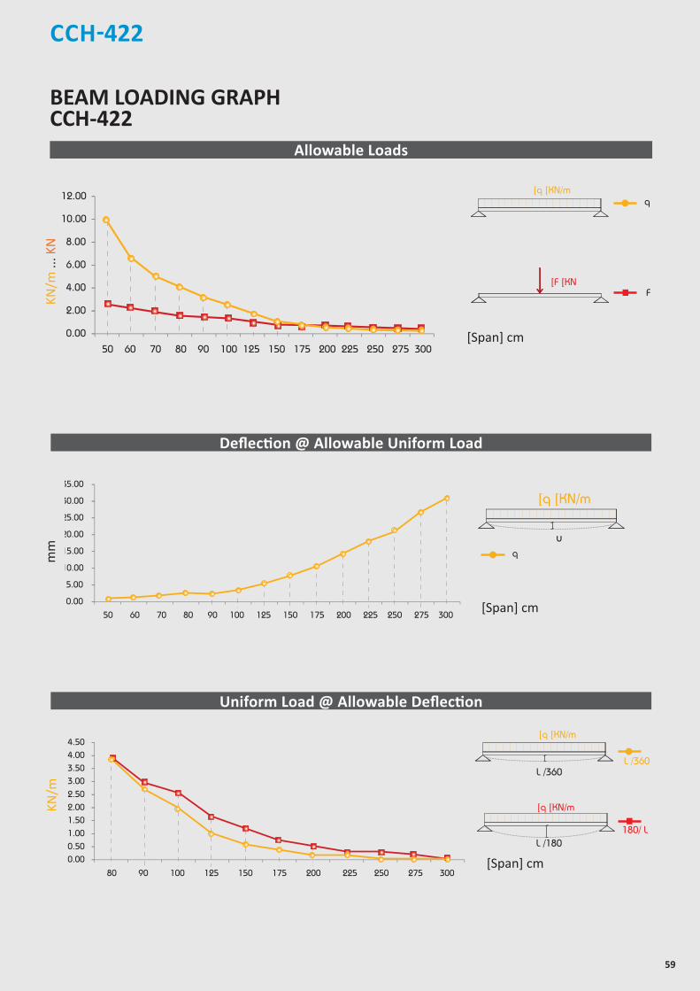
59
CCH-422
8.00
10.00
12.00
0.00
2.00
4.00
6.00
50 60 70 80 90 100 125 150 175 200 225 250 275 300
25.00
30.00
35.00
0.00
5.00
10.00
15.00
20.00
50 60 70 80 90 100 125 150 175 200 225 250 275 300
3.00
3.50
4.00
4.50
0.00
0.50
1.00
1.50
2.00
2.50
80 90 100 125 150 175 200 225 250 275 300
[Span] cm
[Span] cm
BEAM LOADING GRAPH CCH-422
Allowable Loads
Deflection @ Allowable Uniform Load
Uniform Load @ Allowable Deflection
[Span] cm
mm
Chosen Material:Allowable Bending Stress 21,82 kN/cm²Allowable Shear Stress 12,60 kN/cm²Modulus of Elasticity 21.000 kN/cm²
40B = S 235 JRG2
C-Channel:Area of Shear (Az)
1,67 cm
Moment of Inertia (Iy)
5,87 cm
Moment of Inertia (Iz
y
z
)
8,76 cm
min. Section Modulus (Sy)
2,72 cm
Warping Constant (Iw)
171,52 cm
Torsional Constant (IT)
0,07 cm
Plastic Moment cap. (Mpl,y)
0,82 kNm
Self weight (G)
2,32 kg/m
C 41x41x2,52
4
4
3
6
4
cmcmcmcmcmcmkNmkg/m
2
4
4
3
6
4
C-Channel:Cross Section Area (A) cm2
Moment of Inertia (I ) cm4
4Moment of Inertia (I ) cmSelf Weight (G) kg/m
^
Chosen Material:Allowable Bending Stress 21,82 kN/cm²Allowable Shear Stress 12,60 kN/cm²Modulus of Elasticity 21.000 kN/cm²
40B = S 235 JRG2
C-Channel:Area of Shear (Az)
1,67 cm
Moment of Inertia (Iy)
5,87 cm
Moment of Inertia (Iz
y
z
)
8,76 cm
min. Section Modulus (Sy)
2,72 cm
Warping Constant (Iw)
171,52 cm
Torsional Constant (IT)
0,07 cm
Plastic Moment cap. (Mpl,y)
0,82 kNm
Self weight (G)
2,32 kg/m
C 41x41x2,52
4
4
3
6
4
cmcmcmcmcmcmkNmkg/m
2
4
4
3
6
4
C-Channel:Cross Section Area (A) cm2
Moment of Inertia (I ) cm4
4Moment of Inertia (I ) cmSelf Weight (G) kg/m
^
F
]q ]KN/m
]F ]KN
q
180/ L
Chosen Material:Allowable Bending Stress 21,82 kN/cm²Allowable Shear Stress 12,60 kN/cm²Modulus of Elasticity 21.000 kN/cm²
40B = S 235 JRG2
C-Channel:Area of Shear (Az)
1,67 cm
Moment of Inertia (Iy)
5,87 cm
Moment of Inertia (Iz
y
z
)
8,76 cm
min. Section Modulus (Sy)
2,72 cm
Warping Constant (Iw)
171,52 cm
Torsional Constant (IT)
0,07 cm
Plastic Moment cap. (Mpl,y)
0,82 kNm
Self weight (G)
2,32 kg/m
C 41x41x2,52
4
4
3
6
4
cmcmcmcmcmcmkNmkg/m
2
4
4
3
6
4
C-Channel:Cross Section Area (A) cm2
Moment of Inertia (I ) cm4
4Moment of Inertia (I ) cmSelf Weight (G) kg/m
^
L /360
Chosen Material:Allowable Bending Stress 21,82 kN/cm²Allowable Shear Stress 12,60 kN/cm²Modulus of Elasticity 21.000 kN/cm²
40B = S 235 JRG2
C-Channel:Area of Shear (Az)
1,67 cm
Moment of Inertia (Iy)
5,87 cm
Moment of Inertia (Iz
y
z
)
8,76 cm
min. Section Modulus (Sy)
2,72 cm
Warping Constant (Iw)
171,52 cm
Torsional Constant (IT)
0,07 cm
Plastic Moment cap. (Mpl,y)
0,82 kNm
Self weight (G)
2,32 kg/m
C 41x41x2,52
4
4
3
6
4
cmcmcmcmcmcmkNmkg/m
2
4
4
3
6
4
C-Channel:Cross Section Area (A) cm2
Moment of Inertia (I ) cm4
4Moment of Inertia (I ) cmSelf Weight (G) kg/m
^
L /180
]q ]KN/m
L /360
]q ]KN/m
Chosen Material:Allowable Bending Stress 21,82 kN/cm²Allowable Shear Stress 12,60 kN/cm²Modulus of Elasticity 21.000 kN/cm²
40B = S 235 JRG2
C-Channel:Area of Shear (Az)
1,67 cm
Moment of Inertia (Iy)
5,87 cm
Moment of Inertia (Iz
y
z
)
8,76 cm
min. Section Modulus (Sy)
2,72 cm
Warping Constant (Iw)
171,52 cm
Torsional Constant (IT)
0,07 cm
Plastic Moment cap. (Mpl,y)
0,82 kNm
Self weight (G)
2,32 kg/m
C 41x41x2,52
4
4
3
6
4
cmcmcmcmcmcmkNmkg/m
2
4
4
3
6
4
C-Channel:Cross Section Area (A) cm2
Moment of Inertia (I ) cm4
4Moment of Inertia (I ) cmSelf Weight (G) kg/m
^
u
]q ]KN/m
q
KN/m
... K
NKN
/m
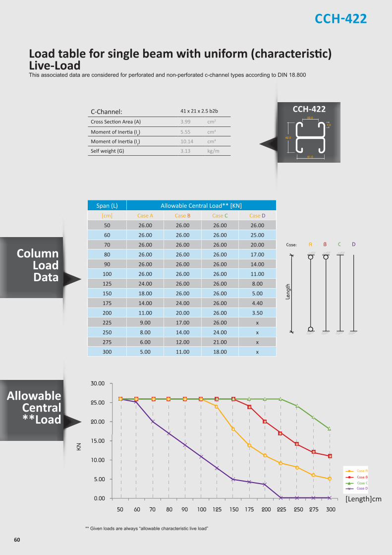
60
CCH-422Z
Z
YY
Z
Z
YY
Z
Z
YY
Z
Z
Y Y
21.0
7.0
41.0
21.0
41.0
22.0
42.0
7.0
41.0
22.0
41.0
7.0
41.0
41.0
41.0
22.0
82.0
7.0
41.0
22.0
50
30
13
allowable uniform Load
ACase:
Length
B C D
Leng
th
C-Channel: 41 x 21 x 2.5 b2b
Cross Section Area (A) 3.99 cm2
Moment of Inertia (Iy) 5.55 cm4
Moment of Inertia (Iz) 10.14 cm4
Self weight (G) 3.13 kg/m
Span (L) Allowable Central Load** [KN]
[cm] Case A Case B Case C Case D
50 26.00 26.00 26.00 26.00
60 26.00 26.00 26.00 25.00
70 26.00 26.00 26.00 20.00
80 26.00 26.00 26.00 17.00
90 26.00 26.00 26.00 14.00
100 26.00 26.00 26.00 11.00
125 24.00 26.00 26.00 8.00
150 18.00 26.00 26.00 5.00
175 14.00 24.00 26.00 4.40
200 11.00 20.00 26.00 3.50
225 9.00 17.00 26.00 x
250 8.00 14.00 24.00 x
275 6.00 12.00 21.00 x
300 5.00 11.00 18.00 x
** Given loads are always “allowable characteristic live load”
20.00
25.00
30.00
0.00
5.00
10.00
15.00
50 60 70 80 90 100 125 150 175 200 225 250 275 300
KN
[Length]cm
Case A
Case B
Case CCase D
CCH-422
Column LoadData
Load table for single beam with uniform (characteristic) Live-LoadThis associated data are considered for perforated and non-perforated c-channel types according to DIN 18.800
Allowable Central**Load

61
CCH-440/441
* Given loads are always “allowable characteristic live load”
Beam Load Data
C-Channel: 41x41x2.5
Area of Shear (Az) 1.67 cm2
Moment of Inertia (Iy) 5.87 cm4
Moment of Inertia (Iz) 8.76 cm4
min. Section Modulus (Sy) 2.72 cm3
Warping Constant (Iw) 171.52 cm6
Torsional Constant (IT) 0.07 cm4
Plastic Moment cap. (Mpl,y) 0.82 kNm
Self weight (G) 2.32 kg/m
Chosen Material: 40 B = S 235 JRG2
Allowable Bending Stress 21,82 kN/cm2
Allowable Shear Stress 12,60 kN/cm2
Modulus of Elasticity 21.000 kN/cm2
@ *Uniform Load
Span (L) Allowable Load* Deflection L / 360 L / 180
[cm] [q [kN/m [F [kN [U [mm [L /X] [q [kN/m [q [kN/m
50 10.10 2.50 0.83 600 10.10 10.10
60 7.00 2.10 1.20 500 7.00 7.00
70 5.20 1.80 1.65 420 5.20 5.20
80 4.00 1.60 2.16 370 4.00 4.00
90 3.10 1.40 2.69 340 2.90 3.10
100 2.50 1.30 3.30 300 2.10 2.50
125 1.60 1.00 5.16 240 1.10 1.60
150 1.10 0.80 7.35 200 0.60 1.10
175 0.80 0.70 9.91 180 0.40 0.80
200 0.63 0.60 13.31 150 0.30 0.50
225 0.50 0.60 16.92 130 0.20 0.40
250 0.41 0.50 21.15 120 x 0.30
275 0.33 0.50 24.92 110 x 0.20
300 0.28 0.40 29.95 100 x x
Z
Z
YY
Z
Z
YY
Z
Z
YY
Z
Z
Y Y
21.0
7.0
41.0
21.0
41.0
22.0
42.0
7.0
41.0
22.0
41.0
7.0
41.0
41.0
41.0
22.0
82.0
7.0
41.0
22.0
50
30
13
Chosen Material:Allowable Bending Stress 21,82 kN/cm²Allowable Shear Stress 12,60 kN/cm²Modulus of Elasticity 21.000 kN/cm²
40B = S 235 JRG2
C-Channel:Area of Shear (Az)
1,67 cm
Moment of Inertia (Iy)
5,87 cm
Moment of Inertia (Iz
y
z
)
8,76 cm
min. Section Modulus (Sy)
2,72 cm
Warping Constant (Iw)
171,52 cm
Torsional Constant (IT)
0,07 cm
Plastic Moment cap. (Mpl,y)
0,82 kNm
Self weight (G)
2,32 kg/m
C 41x41x2,52
4
4
3
6
4
cmcmcmcmcmcmkNmkg/m
2
4
4
3
6
4
C-Channel:Cross Section Area (A) cm2
Moment of Inertia (I ) cm4
4Moment of Inertia (I ) cmSelf Weight (G) kg/m
^
Allowable Load
Span
F
Chosen Material:Allowable Bending Stress 21,82 kN/cm²Allowable Shear Stress 12,60 kN/cm²Modulus of Elasticity 21.000 kN/cm²
40B = S 235 JRG2
C-Channel:Area of Shear (Az)
1,67 cm
Moment of Inertia (Iy)
5,87 cm
Moment of Inertia (Iz
y
z
)
8,76 cm
min. Section Modulus (Sy)
2,72 cm
Warping Constant (Iw)
171,52 cm
Torsional Constant (IT)
0,07 cm
Plastic Moment cap. (Mpl,y)
0,82 kNm
Self weight (G)
2,32 kg/m
C 41x41x2,52
4
4
3
6
4
cmcmcmcmcmcmkNmkg/m
2
4
4
3
6
4
C-Channel:Cross Section Area (A) cm2
Moment of Inertia (I ) cm4
4Moment of Inertia (I ) cmSelf Weight (G) kg/m
^
Allowable Uniform Load
Span
q
C C H - 4 4 0
Thickness : 2.5 mmStandard Length : 3.00 m Finishes : Pre-Galvanized, Hot-Dip Galvanized.
Load table for single beam with uniform (characteristic) Live-LoadThis associated data are considered for perforated and non-perforated c-channel types according to DIN 18.800
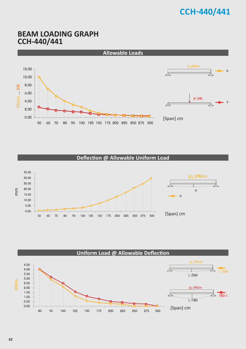
62
CCH-440/441
8.00
10.00
12.00
0.00
2.00
4.00
6.00
50 60 70 80 90 100 125 150 175 200 225 250 275 300
25.00
30.00
35.00
0.00
5.00
10.00
15.00
20.00
50 60 70 80 90 100 125 150 175 200 225 250 275 300
3.00
3.50
4.00
4.50
0.00
0.50
1.00
1.50
2.00
2.50
80 90 100 125 150 175 200 225 250 275 300
[Span] cm
BEAM LOADING GRAPH CCH-440/441
[Span] cm
Allowable Loads
Deflection @ Allowable Uniform Load
Uniform Load @ Allowable Deflection
[Span] cm
mm
Chosen Material:Allowable Bending Stress 21,82 kN/cm²Allowable Shear Stress 12,60 kN/cm²Modulus of Elasticity 21.000 kN/cm²
40B = S 235 JRG2
C-Channel:Area of Shear (Az)
1,67 cm
Moment of Inertia (Iy)
5,87 cm
Moment of Inertia (Iz
y
z
)
8,76 cm
min. Section Modulus (Sy)
2,72 cm
Warping Constant (Iw)
171,52 cm
Torsional Constant (IT)
0,07 cm
Plastic Moment cap. (Mpl,y)
0,82 kNm
Self weight (G)
2,32 kg/m
C 41x41x2,52
4
4
3
6
4
cmcmcmcmcmcmkNmkg/m
2
4
4
3
6
4
C-Channel:Cross Section Area (A) cm2
Moment of Inertia (I ) cm4
4Moment of Inertia (I ) cmSelf Weight (G) kg/m
^
Chosen Material:Allowable Bending Stress 21,82 kN/cm²Allowable Shear Stress 12,60 kN/cm²Modulus of Elasticity 21.000 kN/cm²
40B = S 235 JRG2
C-Channel:Area of Shear (Az)
1,67 cm
Moment of Inertia (Iy)
5,87 cm
Moment of Inertia (Iz
y
z
)
8,76 cm
min. Section Modulus (Sy)
2,72 cm
Warping Constant (Iw)
171,52 cm
Torsional Constant (IT)
0,07 cm
Plastic Moment cap. (Mpl,y)
0,82 kNm
Self weight (G)
2,32 kg/m
C 41x41x2,52
4
4
3
6
4
cmcmcmcmcmcmkNmkg/m
2
4
4
3
6
4
C-Channel:Cross Section Area (A) cm2
Moment of Inertia (I ) cm4
4Moment of Inertia (I ) cmSelf Weight (G) kg/m
^
F
]q ]KN/m
]F ]KN
q
180/ L
Chosen Material:Allowable Bending Stress 21,82 kN/cm²Allowable Shear Stress 12,60 kN/cm²Modulus of Elasticity 21.000 kN/cm²
40B = S 235 JRG2
C-Channel:Area of Shear (Az)
1,67 cm
Moment of Inertia (Iy)
5,87 cm
Moment of Inertia (Iz
y
z
)
8,76 cm
min. Section Modulus (Sy)
2,72 cm
Warping Constant (Iw)
171,52 cm
Torsional Constant (IT)
0,07 cm
Plastic Moment cap. (Mpl,y)
0,82 kNm
Self weight (G)
2,32 kg/m
C 41x41x2,52
4
4
3
6
4
cmcmcmcmcmcmkNmkg/m
2
4
4
3
6
4
C-Channel:Cross Section Area (A) cm2
Moment of Inertia (I ) cm4
4Moment of Inertia (I ) cmSelf Weight (G) kg/m
^
L /360
Chosen Material:Allowable Bending Stress 21,82 kN/cm²Allowable Shear Stress 12,60 kN/cm²Modulus of Elasticity 21.000 kN/cm²
40B = S 235 JRG2
C-Channel:Area of Shear (Az)
1,67 cm
Moment of Inertia (Iy)
5,87 cm
Moment of Inertia (Iz
y
z
)
8,76 cm
min. Section Modulus (Sy)
2,72 cm
Warping Constant (Iw)
171,52 cm
Torsional Constant (IT)
0,07 cm
Plastic Moment cap. (Mpl,y)
0,82 kNm
Self weight (G)
2,32 kg/m
C 41x41x2,52
4
4
3
6
4
cmcmcmcmcmcmkNmkg/m
2
4
4
3
6
4
C-Channel:Cross Section Area (A) cm2
Moment of Inertia (I ) cm4
4Moment of Inertia (I ) cmSelf Weight (G) kg/m
^
L /180
]q ]KN/m
L /360
]q ]KN/m
Chosen Material:Allowable Bending Stress 21,82 kN/cm²Allowable Shear Stress 12,60 kN/cm²Modulus of Elasticity 21.000 kN/cm²
40B = S 235 JRG2
C-Channel:Area of Shear (Az)
1,67 cm
Moment of Inertia (Iy)
5,87 cm
Moment of Inertia (Iz
y
z
)
8,76 cm
min. Section Modulus (Sy)
2,72 cm
Warping Constant (Iw)
171,52 cm
Torsional Constant (IT)
0,07 cm
Plastic Moment cap. (Mpl,y)
0,82 kNm
Self weight (G)
2,32 kg/m
C 41x41x2,52
4
4
3
6
4
cmcmcmcmcmcmkNmkg/m
2
4
4
3
6
4
C-Channel:Cross Section Area (A) cm2
Moment of Inertia (I ) cm4
4Moment of Inertia (I ) cmSelf Weight (G) kg/m
^
u
]q ]KN/m
q
KN/m
KN/m
... K
N
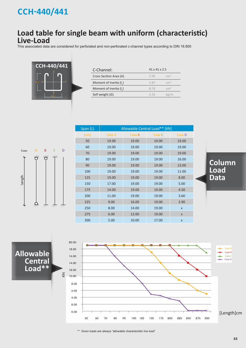
63
CCH-440/441
** Given loads are always “allowable characteristic live load”
allowable uniform Load
ACase:
Length
B C D
Leng
th
C-Channel: 41 x 41 x 2.5
Cross Section Area (A) 2.95 cm2
Moment of Inertia (Iy) 5.87 cm4
Moment of Inertia (Iz) 8.76 cm4
Self weight (G) 2.32 kg/m
Span (L) Allowable Central Load** [KN]
[cm] Case A Case B Case C Case D
50 19.00 19.00 19.00 19.00
60 19.00 19.00 19.00 19.00
70 19.00 19.00 19.00 19.00
80 19.00 19.00 19.00 16.00
90 19.00 19.00 19.00 13.00
100 19.00 19.00 19.00 11.00
125 19.00 19.00 19.00 8.00
150 17.00 19.00 19.00 5.00
175 14.00 19.00 19.00 4.50
200 11.00 19.00 19.00 3.60
225 9.00 16.00 19.00 2.90
250 8.00 14.00 19.00 x
275 6.00 12.00 19.00 x
300 5.00 10.00 17.00 x
16.00
18.00
20.00
12.00
10.00
14.00
6.00
8.00
2.00
0.00
4.00
50 60 70 80 90 100 125 150 175 200 225 250 275 300
KN
[Length]cm
Case A
Case B
Case CCase D
Allowable Central Load**
Column Load Data
Z
Z
YY
Z
Z
YY
Z
Z
YY
Z
Z
Y Y
21.0
7.0
41.0
21.0
41.0
22.0
42.0
7.0
41.0
22.0
41.0
7.0
41.0
41.0
41.0
22.0
82.0
7.0
41.0
22.0
50
30
13
Load table for single beam with uniform (characteristic) Live-LoadThis associated data are considered for perforated and non-perforated c-channel types according to DIN 18.800
CCH-440/441

64
C-Channel: 41x41x2.5 b2b
Area of Shear (Az) 2.37 cm2
Moment of Inertia (Iy) 34.08 cm4
Moment of Inertia (Iz) 17.56 cm4
min. Section Modulus (Sy) 8.31 cm3
Warping Constant (Iw) 140.95 cm6
Torsional Constant (IT) 0.16 cm4
Plastic Moment cap. (Mpl,y) 2.51 kNm
Self weight (G) 4.70 kg/m
Chosen Material: 40 B = S 235 JRG2
Allowable Bending Stress 21,82 kN/cm2
Allowable Shear Stress 12,60 kN/cm2
Modulus of Elasticity 21.000 kN/cm2
CCH-442
Z
Z
YY
Z
Z
YY
Z
Z
YY
Z
Z
Y Y
21.0
7.0
41.0
21.0
41.0
22.0
42.0
7.0
41.0
22.0
41.0
7.0
41.0
41.0
41.0
22.0
82.0
7.0
41.0
22.0
50
30
13
C C H - 4 4 2
* Given loads are always “allowable characteristic live load”
Beam Load Data
Uniform Load* @
Span (L) Allowable Load* Deflection L / 360 L / 180
[cm] q [kN/m] F [kN] U [mm] [L /X] q [kN/m] q [kN/m]
50 30.90 7.70 0.44 1.140 30.90 30.90
60 21.50 6.50 0.63 950 21.50 21.50
70 15.80 5.50 0.86 810 15.80 15.80
80 12.10 4.80 1.13 710 12.10 12.10
90 9.60 4.30 1.43 630 9.60 9.60
100 7.70 3.90 1.75 570 7.70 7.70
125 5.00 3.10 2.78 450 5.00 5.00
150 3.40 2.60 3.91 380 3.40 3.40
175 2.50 2.20 5.33 330 2.30 2.50
200 1.90 1.90 6.91 290 1.50 1.90
225 1.50 1.70 8.74 260 1.10 1.50
250 1.20 1.50 10.66 230 0.80 1.20
275 1.00 1.40 13.01 210 0.60 1.00
300 0.77 1.20 14.18 210 0.50 0.80
Chosen Material:Allowable Bending Stress 21,82 kN/cm²Allowable Shear Stress 12,60 kN/cm²Modulus of Elasticity 21.000 kN/cm²
40B = S 235 JRG2
C-Channel:Area of Shear (Az)
1,67 cm
Moment of Inertia (Iy)
5,87 cm
Moment of Inertia (Iz
y
z
)
8,76 cm
min. Section Modulus (Sy)
2,72 cm
Warping Constant (Iw)
171,52 cm
Torsional Constant (IT)
0,07 cm
Plastic Moment cap. (Mpl,y)
0,82 kNm
Self weight (G)
2,32 kg/m
C 41x41x2,52
4
4
3
6
4
cmcmcmcmcmcmkNmkg/m
2
4
4
3
6
4
C-Channel:Cross Section Area (A) cm2
Moment of Inertia (I ) cm4
4Moment of Inertia (I ) cmSelf Weight (G) kg/m
^
Allowable Load
Span
F
Chosen Material:Allowable Bending Stress 21,82 kN/cm²Allowable Shear Stress 12,60 kN/cm²Modulus of Elasticity 21.000 kN/cm²
40B = S 235 JRG2
C-Channel:Area of Shear (Az)
1,67 cm
Moment of Inertia (Iy)
5,87 cm
Moment of Inertia (Iz
y
z
)
8,76 cm
min. Section Modulus (Sy)
2,72 cm
Warping Constant (Iw)
171,52 cm
Torsional Constant (IT)
0,07 cm
Plastic Moment cap. (Mpl,y)
0,82 kNm
Self weight (G)
2,32 kg/m
C 41x41x2,52
4
4
3
6
4
cmcmcmcmcmcmkNmkg/m
2
4
4
3
6
4
C-Channel:Cross Section Area (A) cm2
Moment of Inertia (I ) cm4
4Moment of Inertia (I ) cmSelf Weight (G) kg/m
^
Allowable Uniform Load
Span
q
Thickness : 2.5 mmStandard Length : 3.00 m Finishes : Pre-Galvanized, Hot-Dip Galvanized.
Load table for single beam with uniform (characteristic) Live-LoadThis associated data are considered for perforated and non-perforated c-channel types according to DIN 18.800
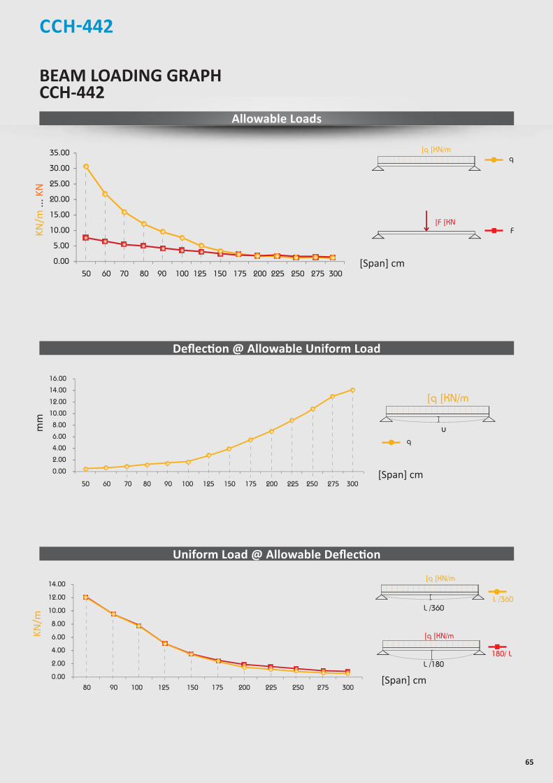
65
CCH-442
25.00
30.00
35.00
0.00
5.00
10.00
15.00
20.00
50 60 70 80 90 100 125 150 175 200 225 250 275 300
10.00
12.00
14.00
16.00
0.00
2.00
4.00
6.00
8.00
50 60 70 80 90 100 125 150 175 200 225 250 275 300
10.00
12.00
14.00
0.00
2.00
4.00
6.00
8.00
80 90 100 125 150 175 200 225 250 275 300
[Span] cm
[Span] cm
BEAM LOADING GRAPH CCH-442
Allowable Loads
Deflection @ Allowable Uniform Load
Uniform Load @ Allowable Deflection
[Span] cm
mm
Chosen Material:Allowable Bending Stress 21,82 kN/cm²Allowable Shear Stress 12,60 kN/cm²Modulus of Elasticity 21.000 kN/cm²
40B = S 235 JRG2
C-Channel:Area of Shear (Az)
1,67 cm
Moment of Inertia (Iy)
5,87 cm
Moment of Inertia (Iz
y
z
)
8,76 cm
min. Section Modulus (Sy)
2,72 cm
Warping Constant (Iw)
171,52 cm
Torsional Constant (IT)
0,07 cm
Plastic Moment cap. (Mpl,y)
0,82 kNm
Self weight (G)
2,32 kg/m
C 41x41x2,52
4
4
3
6
4
cmcmcmcmcmcmkNmkg/m
2
4
4
3
6
4
C-Channel:Cross Section Area (A) cm2
Moment of Inertia (I ) cm4
4Moment of Inertia (I ) cmSelf Weight (G) kg/m
^
Chosen Material:Allowable Bending Stress 21,82 kN/cm²Allowable Shear Stress 12,60 kN/cm²Modulus of Elasticity 21.000 kN/cm²
40B = S 235 JRG2
C-Channel:Area of Shear (Az)
1,67 cm
Moment of Inertia (Iy)
5,87 cm
Moment of Inertia (Iz
y
z
)
8,76 cm
min. Section Modulus (Sy)
2,72 cm
Warping Constant (Iw)
171,52 cm
Torsional Constant (IT)
0,07 cm
Plastic Moment cap. (Mpl,y)
0,82 kNm
Self weight (G)
2,32 kg/m
C 41x41x2,52
4
4
3
6
4
cmcmcmcmcmcmkNmkg/m
2
4
4
3
6
4
C-Channel:Cross Section Area (A) cm2
Moment of Inertia (I ) cm4
4Moment of Inertia (I ) cmSelf Weight (G) kg/m
^
F
]q ]KN/m
]F ]KN
q
180/ L
Chosen Material:Allowable Bending Stress 21,82 kN/cm²Allowable Shear Stress 12,60 kN/cm²Modulus of Elasticity 21.000 kN/cm²
40B = S 235 JRG2
C-Channel:Area of Shear (Az)
1,67 cm
Moment of Inertia (Iy)
5,87 cm
Moment of Inertia (Iz
y
z
)
8,76 cm
min. Section Modulus (Sy)
2,72 cm
Warping Constant (Iw)
171,52 cm
Torsional Constant (IT)
0,07 cm
Plastic Moment cap. (Mpl,y)
0,82 kNm
Self weight (G)
2,32 kg/m
C 41x41x2,52
4
4
3
6
4
cmcmcmcmcmcmkNmkg/m
2
4
4
3
6
4
C-Channel:Cross Section Area (A) cm2
Moment of Inertia (I ) cm4
4Moment of Inertia (I ) cmSelf Weight (G) kg/m
^
L /360
Chosen Material:Allowable Bending Stress 21,82 kN/cm²Allowable Shear Stress 12,60 kN/cm²Modulus of Elasticity 21.000 kN/cm²
40B = S 235 JRG2
C-Channel:Area of Shear (Az)
1,67 cm
Moment of Inertia (Iy)
5,87 cm
Moment of Inertia (Iz
y
z
)
8,76 cm
min. Section Modulus (Sy)
2,72 cm
Warping Constant (Iw)
171,52 cm
Torsional Constant (IT)
0,07 cm
Plastic Moment cap. (Mpl,y)
0,82 kNm
Self weight (G)
2,32 kg/m
C 41x41x2,52
4
4
3
6
4
cmcmcmcmcmcmkNmkg/m
2
4
4
3
6
4
C-Channel:Cross Section Area (A) cm2
Moment of Inertia (I ) cm4
4Moment of Inertia (I ) cmSelf Weight (G) kg/m
^
L /180
]q ]KN/m
L /360
]q ]KN/m
Chosen Material:Allowable Bending Stress 21,82 kN/cm²Allowable Shear Stress 12,60 kN/cm²Modulus of Elasticity 21.000 kN/cm²
40B = S 235 JRG2
C-Channel:Area of Shear (Az)
1,67 cm
Moment of Inertia (Iy)
5,87 cm
Moment of Inertia (Iz
y
z
)
8,76 cm
min. Section Modulus (Sy)
2,72 cm
Warping Constant (Iw)
171,52 cm
Torsional Constant (IT)
0,07 cm
Plastic Moment cap. (Mpl,y)
0,82 kNm
Self weight (G)
2,32 kg/m
C 41x41x2,52
4
4
3
6
4
cmcmcmcmcmcmkNmkg/m
2
4
4
3
6
4
C-Channel:Cross Section Area (A) cm2
Moment of Inertia (I ) cm4
4Moment of Inertia (I ) cmSelf Weight (G) kg/m
^
u
]q ]KN/m
q
KN/m
... K
NKN
/m
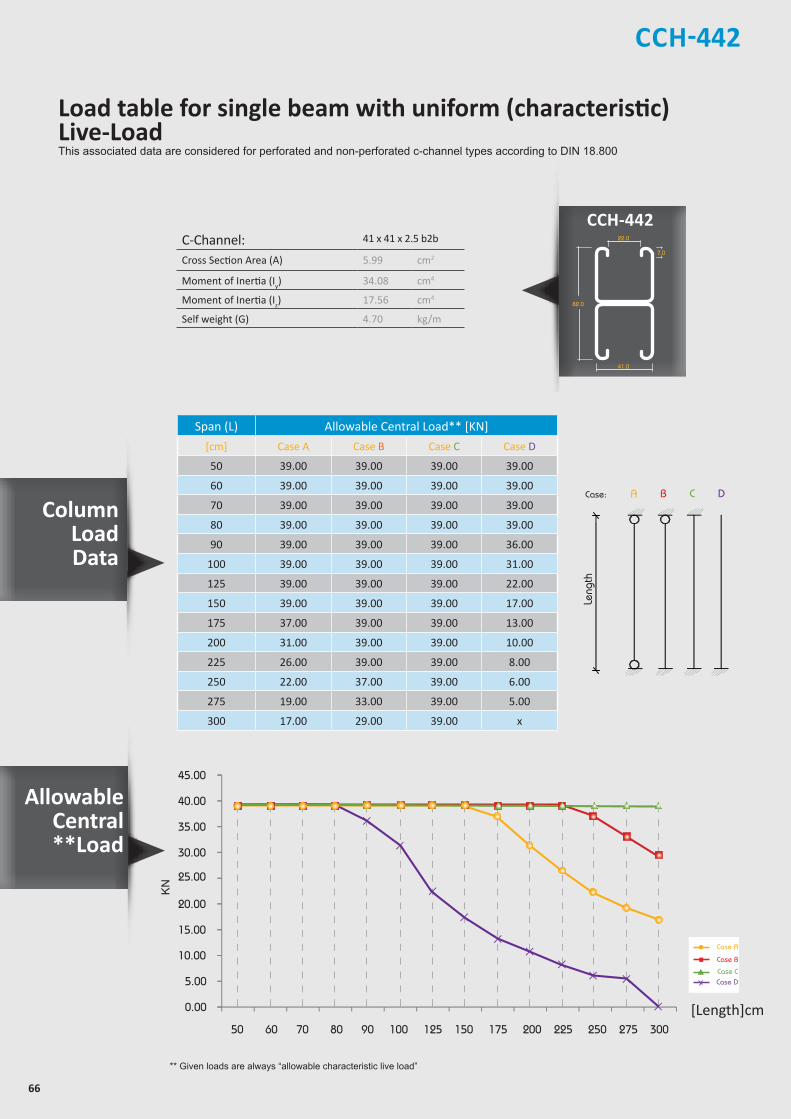
66
CCH-442
Column LoadData
CCH-442Z
Z
YY
Z
Z
YY
Z
Z
YY
Z
Z
Y Y
21.0
7.0
41.0
21.0
41.0
22.0
42.0
7.0
41.0
22.0
41.0
7.0
41.0
41.0
41.0
22.0
82.0
7.0
41.0
22.0
50
30
13
allowable uniform Load
ACase:
Length
B C D
Leng
th
C-Channel: 41 x 41 x 2.5 b2b
Cross Section Area (A) 5.99 cm2
Moment of Inertia (Iy) 34.08 cm4
Moment of Inertia (Iz) 17.56 cm4
Self weight (G) 4.70 kg/m
Span (L) Allowable Central Load** [KN]
[cm] Case A Case B Case C Case D
50 39.00 39.00 39.00 39.00
60 39.00 39.00 39.00 39.00
70 39.00 39.00 39.00 39.00
80 39.00 39.00 39.00 39.00
90 39.00 39.00 39.00 36.00
100 39.00 39.00 39.00 31.00
125 39.00 39.00 39.00 22.00
150 39.00 39.00 39.00 17.00
175 37.00 39.00 39.00 13.00
200 31.00 39.00 39.00 10.00
225 26.00 39.00 39.00 8.00
250 22.00 37.00 39.00 6.00
275 19.00 33.00 39.00 5.00
300 17.00 29.00 39.00 x
** Given loads are always “allowable characteristic live load”
30.00
25.00
35.00
40.00
45.00
0.00
5.00
10.00
15.00
20.00
50 60 70 80 90 100 125 150 175 200 225 250 275 300
KN
[Length]cm
Case A
Case B
Case CCase D
Load table for single beam with uniform (characteristic) Live-LoadThis associated data are considered for perforated and non-perforated c-channel types according to DIN 18.800
Allowable Central**Load

67
Load table for single beam with uniform (characteristic) Live-LoadThis associated data are considered for perforated and non-perforated c-channel types according to DIN 18.800
* Given loads are always “allowable characteristic live load”
Allowable Load
Span
F
Allowable Uniform Load
Span
q
C-Channel: 50 x 25 x 2.5Area of Shear (Az) 0.83 cm2
Moment of Inertia (Iy) 1.78 cm4
Moment of Inertia (Iz) 9.46 cm4
min. Section Modulus (Sy) 1.25 cm3
Warping Constant (Iw) 58.73 cm6
Torsional Constant (IT) 0.06 cm4
Plastic Moment cap. (Mpl,y) 0.41 kNm
Self weight (G) 1.90 kg/m
Chosen Material: S 235 JRG2Allowable Bending Stress 21,82 kN/cm2
Allowable Shear Stress 12,60 kN/cm2
Modulus of Elasticity 21.000 kN/cm2
Thickness : 2.5 mmStandard Length : 3.00 m Finishes : Pre-Galvanized, Hot-Dip Galvanized.
C C H - 2 2 1
Beam Load Data
CCH-460/461
Uniform Load* @
Span (L) Allowable Load* Deflection L / 360 L / 180
[cm] q [kN/m] F [kN] U [mm] [L /X] q [kN/m] q [kN/m]
30 12.90 1.90 0.40 750 12.90 12.90
40 7.30 1.50 0.72 560 7.30 7.30
50 4.70 1.20 1.13 440 4.70 4.70
60 3.20 1.00 1.60 380 3.00 3.20
70 2.40 0.80 2.23 310 1.90 2.40
80 1.80 0.72 2.85 280 1.25 1.82
90 1.40 0.63 3.57 250 0.88 1.44
100 1.20 0.60 4.67 210 0.64 1.16
125 0.74 0.46 7.10 180 0.33 0.65
150 0.52 0.39 10.46 140 0.19 0.38
175 0.38 0.33 14.34 120 x 0.24
200 0.29 0.29 18.94 110 x x
225 0.23 0.26 24.45 90 x x
250 0.19 0.24 31.28 80 x x
275 x x x x x x
300 x x x x x x
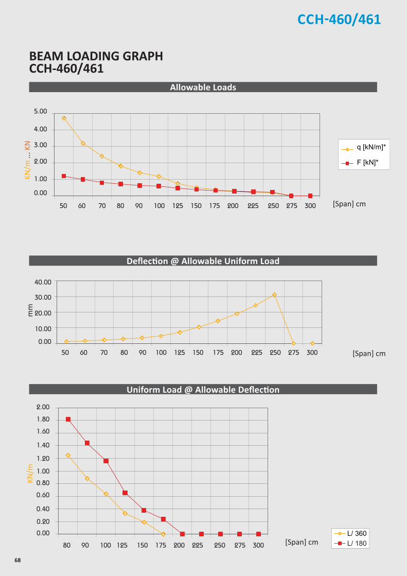
68
CCH-460/461
[Span] cm
BEAM LOADING GRAPH CCH-460/461
[Span] cm
Allowable Loads
Deflection @ Allowable Uniform Load
Uniform Load @ Allowable Deflection
[Span] cm
mm
KN/m
KN/m
... K
N
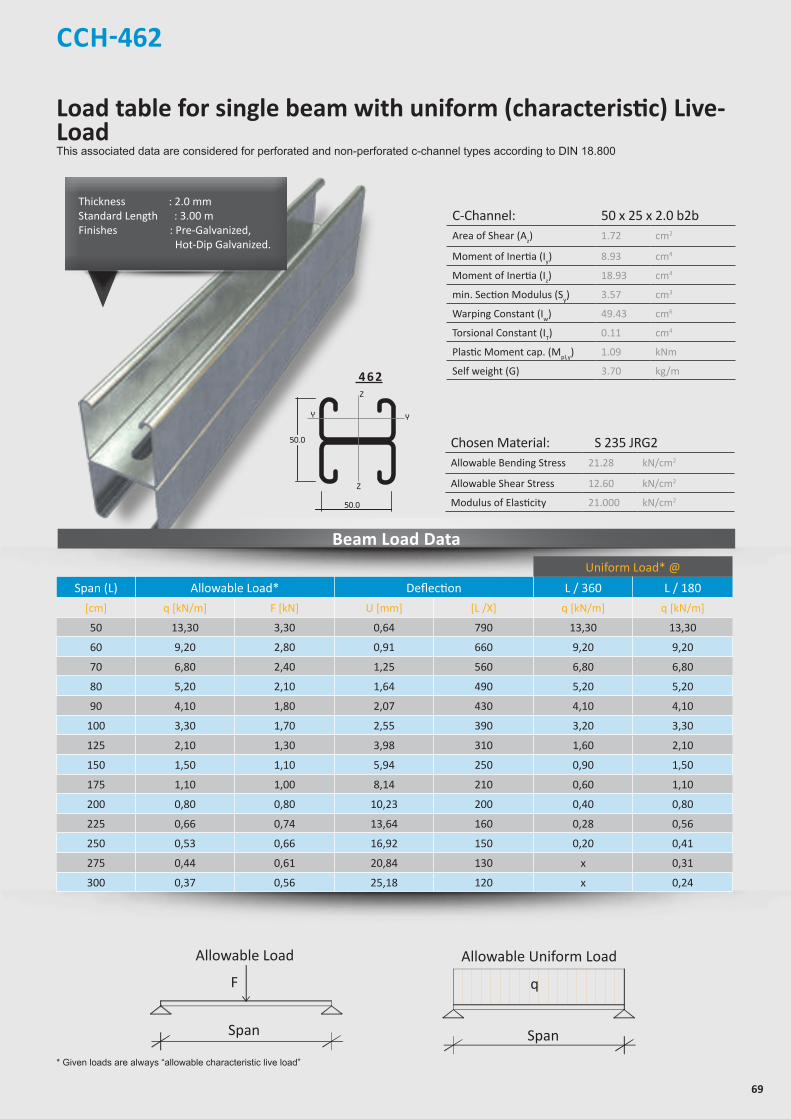
69
Load table for single beam with uniform (characteristic) Live-LoadThis associated data are considered for perforated and non-perforated c-channel types according to DIN 18.800
* Given loads are always “allowable characteristic live load”
Allowable Load
Span
F
Allowable Uniform Load
Span
q
C-Channel: 50 x 25 x 2.0 b2bArea of Shear (Az) 1.72 cm2
Moment of Inertia (Iy) 8.93 cm4
Moment of Inertia (Iz) 18.93 cm4
min. Section Modulus (Sy) 3.57 cm3
Warping Constant (Iw) 49.43 cm6
Torsional Constant (IT) 0.11 cm4
Plastic Moment cap. (Mpl,y) 1.09 kNm
Self weight (G) 3.70 kg/m
Chosen Material: S 235 JRG2Allowable Bending Stress 21.28 kN/cm2
Allowable Shear Stress 12.60 kN/cm2
Modulus of Elasticity 21.000 kN/cm2
Thickness : 2.0 mmStandard Length : 3.00 m Finishes : Pre-Galvanized, Hot-Dip Galvanized.
Beam Load Data
CCH-462
Uniform Load* @
Span (L) Allowable Load* Deflection L / 360 L / 180
[cm] q [kN/m] F [kN] U [mm] [L /X] q [kN/m] q [kN/m]
50 13,30 3,30 0,64 790 13,30 13,30
60 9,20 2,80 0,91 660 9,20 9,20
70 6,80 2,40 1,25 560 6,80 6,80
80 5,20 2,10 1,64 490 5,20 5,20
90 4,10 1,80 2,07 430 4,10 4,10
100 3,30 1,70 2,55 390 3,20 3,30
125 2,10 1,30 3,98 310 1,60 2,10
150 1,50 1,10 5,94 250 0,90 1,50
175 1,10 1,00 8,14 210 0,60 1,10
200 0,80 0,80 10,23 200 0,40 0,80
225 0,66 0,74 13,64 160 0,28 0,56
250 0,53 0,66 16,92 150 0,20 0,41
275 0,44 0,61 20,84 130 x 0,31
300 0,37 0,56 25,18 120 x 0,24
4 6 2

70
[Span] cm
Allowable Loads
Deflection @ Allowable Uniform Load
Uniform Load @ Allowable Deflection
[Span] cm
mm
[Span] cm
Chosen Material:Allowable Bending Stress 21,82 kN/cm²Allowable Shear Stress 12,60 kN/cm²Modulus of Elasticity 21.000 kN/cm²
40B = S 235 JRG2
C-Channel:Area of Shear (Az)
1,67 cm
Moment of Inertia (Iy)
5,87 cm
Moment of Inertia (Iz
y
z
)
8,76 cm
min. Section Modulus (Sy)
2,72 cm
Warping Constant (Iw)
171,52 cm
Torsional Constant (IT)
0,07 cm
Plastic Moment cap. (Mpl,y)
0,82 kNm
Self weight (G)
2,32 kg/m
C 41x41x2,52
4
4
3
6
4
cmcmcmcmcmcmkNmkg/m
2
4
4
3
6
4
C-Channel:Cross Section Area (A) cm2
Moment of Inertia (I ) cm4
4Moment of Inertia (I ) cmSelf Weight (G) kg/m
^
F
]q ]KN/m
]F ]KN
q
180/ L
Chosen Material:Allowable Bending Stress 21,82 kN/cm²Allowable Shear Stress 12,60 kN/cm²Modulus of Elasticity 21.000 kN/cm²
40B = S 235 JRG2
C-Channel:Area of Shear (Az)
1,67 cm
Moment of Inertia (Iy)
5,87 cm
Moment of Inertia (Iz
y
z
)
8,76 cm
min. Section Modulus (Sy)
2,72 cm
Warping Constant (Iw)
171,52 cm
Torsional Constant (IT)
0,07 cm
Plastic Moment cap. (Mpl,y)
0,82 kNm
Self weight (G)
2,32 kg/m
C 41x41x2,52
4
4
3
6
4
cmcmcmcmcmcmkNmkg/m
2
4
4
3
6
4
C-Channel:Cross Section Area (A) cm2
Moment of Inertia (I ) cm4
4Moment of Inertia (I ) cmSelf Weight (G) kg/m
^
L /360
Chosen Material:Allowable Bending Stress 21,82 kN/cm²Allowable Shear Stress 12,60 kN/cm²Modulus of Elasticity 21.000 kN/cm²
40B = S 235 JRG2
C-Channel:Area of Shear (Az)
1,67 cm
Moment of Inertia (Iy)
5,87 cm
Moment of Inertia (Iz
y
z
)
8,76 cm
min. Section Modulus (Sy)
2,72 cm
Warping Constant (Iw)
171,52 cm
Torsional Constant (IT)
0,07 cm
Plastic Moment cap. (Mpl,y)
0,82 kNm
Self weight (G)
2,32 kg/m
C 41x41x2,52
4
4
3
6
4
cmcmcmcmcmcmkNmkg/m
2
4
4
3
6
4
C-Channel:Cross Section Area (A) cm2
Moment of Inertia (I ) cm4
4Moment of Inertia (I ) cmSelf Weight (G) kg/m
^
L /180
]q ]KN/m
L /360
]q ]KN/m
Chosen Material:Allowable Bending Stress 21,82 kN/cm²Allowable Shear Stress 12,60 kN/cm²Modulus of Elasticity 21.000 kN/cm²
40B = S 235 JRG2
C-Channel:Area of Shear (Az)
1,67 cm
Moment of Inertia (Iy)
5,87 cm
Moment of Inertia (Iz
y
z
)
8,76 cm
min. Section Modulus (Sy)
2,72 cm
Warping Constant (Iw)
171,52 cm
Torsional Constant (IT)
0,07 cm
Plastic Moment cap. (Mpl,y)
0,82 kNm
Self weight (G)
2,32 kg/m
C 41x41x2,52
4
4
3
6
4
cmcmcmcmcmcmkNmkg/m
2
4
4
3
6
4
C-Channel:Cross Section Area (A) cm2
Moment of Inertia (I ) cm4
4Moment of Inertia (I ) cmSelf Weight (G) kg/m
^
u
]q ]KN/m
q
KN/m
BEAM LOADING GRAPHCCH-462
KN/m
... K
NCCH-462
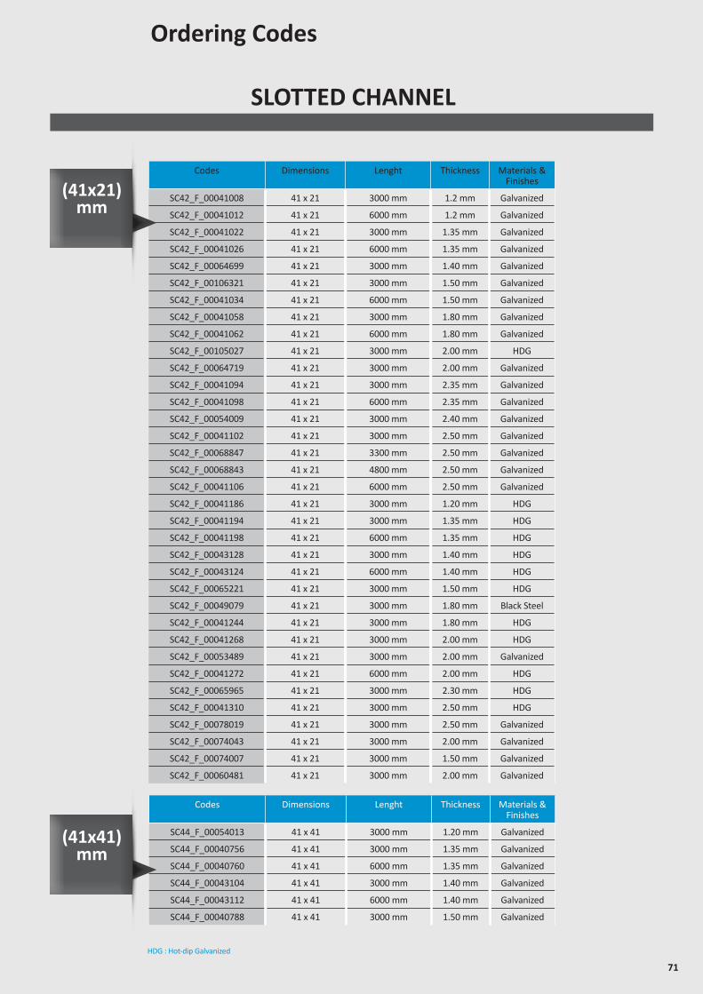
71
SLOTTED CHANNEL
Ordering Codes
Codes Dimensions Lenght Thickness Materials & Finishes
SC42_F_00041008 41 x 21 3000 mm 1.2 mm Galvanized
SC42_F_00041012 41 x 21 6000 mm 1.2 mm Galvanized
SC42_F_00041022 41 x 21 3000 mm 1.35 mm Galvanized
SC42_F_00041026 41 x 21 6000 mm 1.35 mm Galvanized
SC42_F_00064699 41 x 21 3000 mm 1.40 mm Galvanized
SC42_F_00106321 41 x 21 3000 mm 1.50 mm Galvanized
SC42_F_00041034 41 x 21 6000 mm 1.50 mm Galvanized
SC42_F_00041058 41 x 21 3000 mm 1.80 mm Galvanized
SC42_F_00041062 41 x 21 6000 mm 1.80 mm Galvanized
SC42_F_00105027 41 x 21 3000 mm 2.00 mm HDG
SC42_F_00064719 41 x 21 3000 mm 2.00 mm Galvanized
SC42_F_00041094 41 x 21 3000 mm 2.35 mm Galvanized
SC42_F_00041098 41 x 21 6000 mm 2.35 mm Galvanized
SC42_F_00054009 41 x 21 3000 mm 2.40 mm Galvanized
SC42_F_00041102 41 x 21 3000 mm 2.50 mm Galvanized
SC42_F_00068847 41 x 21 3300 mm 2.50 mm Galvanized
SC42_F_00068843 41 x 21 4800 mm 2.50 mm Galvanized
SC42_F_00041106 41 x 21 6000 mm 2.50 mm Galvanized
SC42_F_00041186 41 x 21 3000 mm 1.20 mm HDG
SC42_F_00041194 41 x 21 3000 mm 1.35 mm HDG
SC42_F_00041198 41 x 21 6000 mm 1.35 mm HDG
SC42_F_00043128 41 x 21 3000 mm 1.40 mm HDG
SC42_F_00043124 41 x 21 6000 mm 1.40 mm HDG
SC42_F_00065221 41 x 21 3000 mm 1.50 mm HDG
SC42_F_00049079 41 x 21 3000 mm 1.80 mm Black Steel
SC42_F_00041244 41 x 21 3000 mm 1.80 mm HDG
SC42_F_00041268 41 x 21 3000 mm 2.00 mm HDG
SC42_F_00053489 41 x 21 3000 mm 2.00 mm Galvanized
SC42_F_00041272 41 x 21 6000 mm 2.00 mm HDG
SC42_F_00065965 41 x 21 3000 mm 2.30 mm HDG
SC42_F_00041310 41 x 21 3000 mm 2.50 mm HDG
SC42_F_00078019 41 x 21 3000 mm 2.50 mm Galvanized
SC42_F_00074043 41 x 21 3000 mm 2.00 mm Galvanized
SC42_F_00074007 41 x 21 3000 mm 1.50 mm Galvanized
SC42_F_00060481 41 x 21 3000 mm 2.00 mm Galvanized
Codes Dimensions Lenght Thickness Materials & Finishes
SC44_F_00054013 41 x 41 3000 mm 1.20 mm Galvanized
SC44_F_00040756 41 x 41 3000 mm 1.35 mm Galvanized
SC44_F_00040760 41 x 41 6000 mm 1.35 mm Galvanized
SC44_F_00043104 41 x 41 3000 mm 1.40 mm Galvanized
SC44_F_00043112 41 x 41 6000 mm 1.40 mm Galvanized
SC44_F_00040788 41 x 41 3000 mm 1.50 mm Galvanized
HDG : Hot-dip Galvanized
(41x21) mm
(41x41) mm
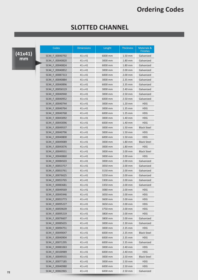
72
Codes Dimensions Lenght Thickness Materials & Finishes
SC44_F_00040792 41 x 41 6000 mm 1.50 mm Galvanized
SC44_F_00040820 41 x 41 3000 mm 1.80 mm Galvanized
SC44_F_00040824 41 x 41 6000 mm 1.80 mm Galvanized
SC44_F_00040852 41 x 41 3000 mm 2.00 mm Galvanized
SC44_F_00087313 41 x 41 6000 mm 2.00 mm Galvanized
SC44_F_00040884 41 x 41 3000 mm 2.35 mm Galvanized
SC44_F_00040896 41 x 41 6000 mm 2.35 mm Galvanized
SC44_F_00056519 41 x 41 3000 mm 2.40 mm Galvanized
SC44_F_00040940 41 x 41 3000 mm 2.50 mm Galvanized
SC44_F_00040952 41 x 41 6000 mm 2.50 mm Galvanized
SC44_F_00040744 41 x 41 3000 mm 1.20 mm HDG
SC44_F_00040764 41 x 41 3000 mm 1.35 mm HDG
SC44_F_00040768 41 x 41 6000 mm 1.35 mm HDG
SC44_F_00043092 41 x 41 3000 mm 1.40 mm HDG
SC44_F_00043096 41 x 41 6000 mm 1.40 mm HDG
SC44_F_00049537 41 x 41 3000 mm 1.50 mm Black Steel
SC44_F_00040796 41 x 41 3000 mm 1.50 mm HDG
SC44_F_00040800 41 x 41 6000 mm 1.50 mm HDG
SC44_F_00049089 41 x 41 3000 mm 1.80 mm Black Steel
SC44_F_00043076 41 x 41 3000 mm 1.80 mm HDG
SC44_F_00049551 41 x 41 3000 mm 2.00 mm Black Steel
SC44_F_00040860 41 x 41 3000 mm 2.00 mm HDG
SC44_F_00084503 41 x 41 3000 mm 2.00 mm Galvanized
SC44_F_00053757 41 x 41 3050 mm 2.00 mm Galvanized
SC44_F_00053761 41 x 41 3150 mm 2.00 mm Galvanized
SC44_F_00076625 41 x 41 3250 mm 2.00 mm Galvanized
SC44_F_00053765 41 x 41 3300 mm 2.00 mm Galvanized
SC44_F_00083681 41 x 41 3350 mm 2.00 mm Galvanized
SC44_F_00049569 41 x 41 3080 mm 2.00 mm HDG
SC44_F_00045946 41 x 41 3050 mm 2.00 mm HDG
SC44_F_00053773 41 x 41 3600 mm 2.00 mm HDG
SC44_F_00095227 41 x 41 3650 mm 2.00 mm HDG
SC44_F_00059639 41 x 41 3750 mm 2.00 mm HDG
SC44_F_00095219 41 x 41 3800 mm 2.00 mm HDG
SC44_F_00076607 41 x 41 3800 mm 2.00 mm Galvanized
SC44_F_00085655 41 x 41 3000 mm 2.30 mm Galvanized
SC44_F_00094751 41 x 41 3000 mm 2.35 mm HDG
SC44_F_00049047 41 x 41 6000 mm 2.35 mm Black Steel
SC44_F_00040904 41 x 41 6000 mm 2.35 mm HDG
SC44_F_00071295 41 x 41 6000 mm 2.35 mm Galvanized
SC44_F_00081063 41 x 41 3000 mm 2.40 mm HDG
SC44_F_00100989 41 x 41 6000 mm 2.40 mm HDG
SC44_F_00049555 41 x 41 3000 mm 2.50 mm Black Steel
SC44_F_00077185 41 x 41 3000 mm 2.50 mm HDG
SC44_F_00040980 41 x 41 6000 mm 2.50 mm HDG
SC44_F_00063965 41 x 41 6000 mm 2.50 mm Galvanized
Ordering Codes
SLOTTED CHANNEL
(41x41) mm
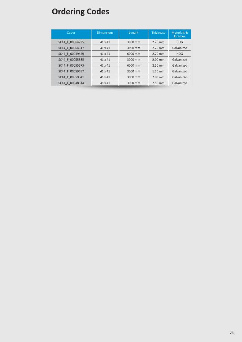
73
Codes Dimensions Lenght Thickness Materials & Finishes
SC44_F_00064225 41 x 41 3000 mm 2.70 mm HDG
SC44_F_00064317 41 x 41 3000 mm 2.70 mm Galvanized
SC44_F_00049429 41 x 41 6000 mm 2.70 mm HDG
SC44_F_00055585 41 x 41 3000 mm 2.00 mm Galvanized
SC44_F_00055573 41 x 41 6000 mm 2.50 mm Galvanized
SC44_F_00059597 41 x 41 3000 mm 1.50 mm Galvanized
SC44_F_00059341 41 x 41 3000 mm 2.00 mm Galvanized
SC44_F_00048314 41 x 41 3000 mm 2.50 mm Galvanized
Ordering Codes
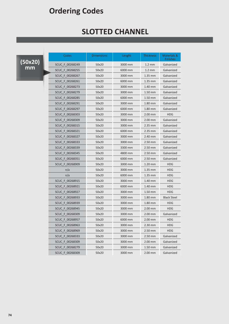
74
SLOTTED CHANNEL
Ordering Codes
Codes Dimensions Lenght Thickness Materials & Finishes
SCUC_F_00268249 50x20 3000 mm 1.2 mm Galvanized
SCUC_F_00268255 50x20 6000 mm 1.2 mm Galvanized
SCUC_F_00268267 50x20 3000 mm 1.35 mm Galvanized
SCUC_F_00268261 50x20 6000 mm 1.35 mm Galvanized
SCUC_F_00268273 50x20 3000 mm 1.40 mm Galvanized
SCUC_F_00268279 50x20 3000 mm 1.50 mm Galvanized
SCUC_F_00268285 50x20 6000 mm 1.50 mm Galvanized
SCUC_F_00268291 50x20 3000 mm 1.80 mm Galvanized
SCUC_F_00268297 50x20 6000 mm 1.80 mm Galvanized
SCUC_F_00268303 50x20 3000 mm 2.00 mm HDG
SCUC_F_00268309 50x20 3000 mm 2.00 mm Galvanized
SCUC_F_00268315 50x20 3000 mm 2.35 mm Galvanized
SCUC_F_00268321 50x20 6000 mm 2.35 mm Galvanized
SCUC_F_00268327 50x20 3000 mm 2.40 mm Galvanized
SCUC_F_00268333 50x20 3000 mm 2.50 mm Galvanized
SCUC_F_00268339 50x20 3300 mm 2.50 mm Galvanized
SCUC_F_00268345 50x20 4800 mm 2.50 mm Galvanized
SCUC_F_00268351 50x20 6000 mm 2.50 mm Galvanized
SCUC_F_00268909 50x20 3000 mm 1.20 mm HDG
n/a 50x20 3000 mm 1.35 mm HDG
n/a 50x20 6000 mm 1.35 mm HDG
SCUC_F_00268915 50x20 3000 mm 1.40 mm HDG
SCUC_F_00268921 50x20 6000 mm 1.40 mm HDG
SCUC_F_00268927 50x20 3000 mm 1.50 mm HDG
SCUC_F_00268933 50x20 3000 mm 1.80 mm Black Steel
SCUC_F_00268939 50x20 3000 mm 1.80 mm HDG
SCUC_F_00268945 50x20 3000 mm 2.00 mm HDG
SCUC_F_00268309 50x20 3000 mm 2.00 mm Galvanized
SCUC_F_00268957 50x20 6000 mm 2.00 mm HDG
SCUC_F_00268963 50x20 3000 mm 2.30 mm HDG
SCUC_F_00268969 50x20 3000 mm 2.50 mm HDG
SCUC_F_00268333 50x20 3000 mm 2.50 mm Galvanized
SCUC_F_00268309 50x20 3000 mm 2.00 mm Galvanized
SCUC_F_00268279 50x20 3000 mm 1.50 mm Galvanized
SCUC_F_00268309 50x20 3000 mm 2.00 mm Galvanized
(50x20) mm
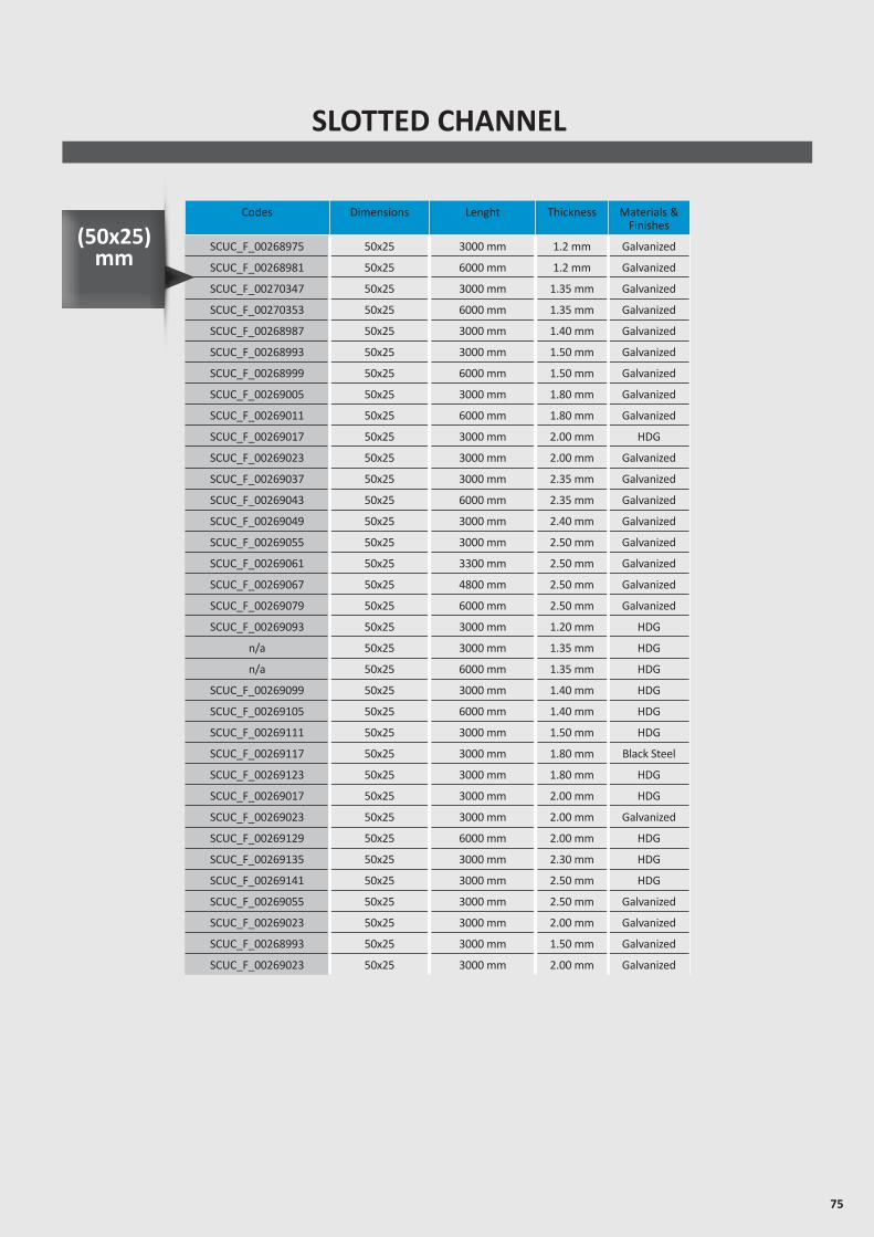
75
SLOTTED CHANNEL
Codes Dimensions Lenght Thickness Materials & Finishes
SCUC_F_00268975 50x25 3000 mm 1.2 mm Galvanized
SCUC_F_00268981 50x25 6000 mm 1.2 mm Galvanized
SCUC_F_00270347 50x25 3000 mm 1.35 mm Galvanized
SCUC_F_00270353 50x25 6000 mm 1.35 mm Galvanized
SCUC_F_00268987 50x25 3000 mm 1.40 mm Galvanized
SCUC_F_00268993 50x25 3000 mm 1.50 mm Galvanized
SCUC_F_00268999 50x25 6000 mm 1.50 mm Galvanized
SCUC_F_00269005 50x25 3000 mm 1.80 mm Galvanized
SCUC_F_00269011 50x25 6000 mm 1.80 mm Galvanized
SCUC_F_00269017 50x25 3000 mm 2.00 mm HDG
SCUC_F_00269023 50x25 3000 mm 2.00 mm Galvanized
SCUC_F_00269037 50x25 3000 mm 2.35 mm Galvanized
SCUC_F_00269043 50x25 6000 mm 2.35 mm Galvanized
SCUC_F_00269049 50x25 3000 mm 2.40 mm Galvanized
SCUC_F_00269055 50x25 3000 mm 2.50 mm Galvanized
SCUC_F_00269061 50x25 3300 mm 2.50 mm Galvanized
SCUC_F_00269067 50x25 4800 mm 2.50 mm Galvanized
SCUC_F_00269079 50x25 6000 mm 2.50 mm Galvanized
SCUC_F_00269093 50x25 3000 mm 1.20 mm HDG
n/a 50x25 3000 mm 1.35 mm HDG
n/a 50x25 6000 mm 1.35 mm HDG
SCUC_F_00269099 50x25 3000 mm 1.40 mm HDG
SCUC_F_00269105 50x25 6000 mm 1.40 mm HDG
SCUC_F_00269111 50x25 3000 mm 1.50 mm HDG
SCUC_F_00269117 50x25 3000 mm 1.80 mm Black Steel
SCUC_F_00269123 50x25 3000 mm 1.80 mm HDG
SCUC_F_00269017 50x25 3000 mm 2.00 mm HDG
SCUC_F_00269023 50x25 3000 mm 2.00 mm Galvanized
SCUC_F_00269129 50x25 6000 mm 2.00 mm HDG
SCUC_F_00269135 50x25 3000 mm 2.30 mm HDG
SCUC_F_00269141 50x25 3000 mm 2.50 mm HDG
SCUC_F_00269055 50x25 3000 mm 2.50 mm Galvanized
SCUC_F_00269023 50x25 3000 mm 2.00 mm Galvanized
SCUC_F_00268993 50x25 3000 mm 1.50 mm Galvanized
SCUC_F_00269023 50x25 3000 mm 2.00 mm Galvanized
(50x25) mm

76
PLAIN CHANNEL
Codes Dimensions Lenght Thickness Materials & Finishes
SC42_F_00041110 41 x 21 3000 mm 1.20 mm Galvanized
SC42_F_00041114 41 x 21 6000 mm 1.20 mm Galvanized
SC42_F_00041118 41 x 21 3000 mm 1.35 mm Galvanized
SC42_F_00041122 41 x 21 6000 mm 1.35 mm Galvanized
SC42_F_00043148 41 x 21 3000 mm 1.40 mm Galvanized
SC42_F_00043152 41 x 21 6000 mm 1.40 mm Galvanized
SC42_F_00041126 41 x 21 3000 mm 1.50 mm Galvanized
SC42_F_00041130 41 x 21 6000 mm 1.50 mm Galvanized
SC42_F_00041154 41 x 21 3000 mm 1.80 mm Galvanized
SC42_F_00041158 41 x 21 6000 mm 1.80 mm Galvanized
SC42_F_00041162 41 x 21 3000 mm 2.00 mm Galvanized
SC42_F_00041166 41 x 21 6000 mm 2.00 mm Galvanized
SC42_F_00041170 41 x 21 3000 mm 2.35 mm Galvanized
SC42_F_00041174 41 x 21 6000 mm 2.35 mm Galvanized
SC42_F_00041178 41 x 21 3000 mm 2.50 mm Galvanized
SC42_F_00041182 41 x 21 6000 mm 2.50 mm Galvanized
SC42_F_00041190 41 x 21 3000 mm 1.20 mm HDG
SC42_F_00041212 41 x 21 3000 mm 1.35 mm HDG
SC42_F_00041216 41 x 21 6000 mm 1.35 mm HDG
SC42_F_00043132 41 x 21 3000 mm 1.40 mm HDG
SC42_F_00043116 41 x 21 6000 mm 1.40 mm HDG
SC42_F_00041228 41 x 21 3000 mm 1.50 mm HDG
SC42_F_00041238 41 x 21 6000 mm 1.50 mm HDG
SC42_F_00041252 41 x 21 3000 mm 1.80 mm HDG
SC42_F_00041264 41 x 21 6000 mm 1.80 mm HDG
SC42_F_00041278 41 x 21 3000 mm 2.00 mm HDG
SC42_F_00067931 41 x 21 3000 mm 2.00 mm Galvanized
SC42_F_00041282 41 x 21 6000 mm 2.00 mm HDG
SC42_F_00048938 41 x 21 6000 mm 2.00 mm Galvanized
SC42_F_00041294 41 x 21 3000 mm 2.35 mm HDG
SC42_F_00074871 41 x 21 3000 mm 2.35 mm Galvanized
SC42_F_00041298 41 x 21 6000 mm 2.35 mm HDG
SC42_F_00041318 41 x 21 3000 mm 2.50 mm HDG
SC42_F_00067761 41 x 21 5000 mm 2.50 mm Galvanized
SC42_F_00041322 41 x 21 6000 mm 2.50 mm HDG
HDG : Hot-dip Galvanized
(41x21) mm
Ordering Codes
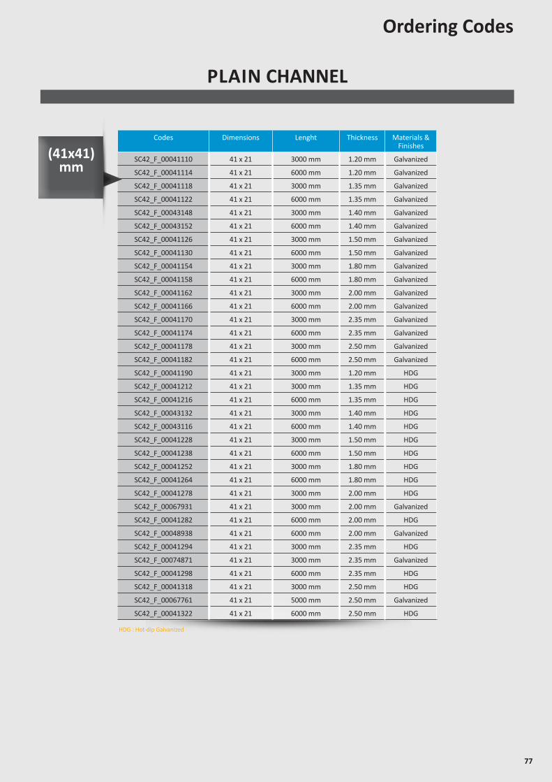
77
Codes Dimensions Lenght Thickness Materials & Finishes
SC42_F_00041110 41 x 21 3000 mm 1.20 mm Galvanized
SC42_F_00041114 41 x 21 6000 mm 1.20 mm Galvanized
SC42_F_00041118 41 x 21 3000 mm 1.35 mm Galvanized
SC42_F_00041122 41 x 21 6000 mm 1.35 mm Galvanized
SC42_F_00043148 41 x 21 3000 mm 1.40 mm Galvanized
SC42_F_00043152 41 x 21 6000 mm 1.40 mm Galvanized
SC42_F_00041126 41 x 21 3000 mm 1.50 mm Galvanized
SC42_F_00041130 41 x 21 6000 mm 1.50 mm Galvanized
SC42_F_00041154 41 x 21 3000 mm 1.80 mm Galvanized
SC42_F_00041158 41 x 21 6000 mm 1.80 mm Galvanized
SC42_F_00041162 41 x 21 3000 mm 2.00 mm Galvanized
SC42_F_00041166 41 x 21 6000 mm 2.00 mm Galvanized
SC42_F_00041170 41 x 21 3000 mm 2.35 mm Galvanized
SC42_F_00041174 41 x 21 6000 mm 2.35 mm Galvanized
SC42_F_00041178 41 x 21 3000 mm 2.50 mm Galvanized
SC42_F_00041182 41 x 21 6000 mm 2.50 mm Galvanized
SC42_F_00041190 41 x 21 3000 mm 1.20 mm HDG
SC42_F_00041212 41 x 21 3000 mm 1.35 mm HDG
SC42_F_00041216 41 x 21 6000 mm 1.35 mm HDG
SC42_F_00043132 41 x 21 3000 mm 1.40 mm HDG
SC42_F_00043116 41 x 21 6000 mm 1.40 mm HDG
SC42_F_00041228 41 x 21 3000 mm 1.50 mm HDG
SC42_F_00041238 41 x 21 6000 mm 1.50 mm HDG
SC42_F_00041252 41 x 21 3000 mm 1.80 mm HDG
SC42_F_00041264 41 x 21 6000 mm 1.80 mm HDG
SC42_F_00041278 41 x 21 3000 mm 2.00 mm HDG
SC42_F_00067931 41 x 21 3000 mm 2.00 mm Galvanized
SC42_F_00041282 41 x 21 6000 mm 2.00 mm HDG
SC42_F_00048938 41 x 21 6000 mm 2.00 mm Galvanized
SC42_F_00041294 41 x 21 3000 mm 2.35 mm HDG
SC42_F_00074871 41 x 21 3000 mm 2.35 mm Galvanized
SC42_F_00041298 41 x 21 6000 mm 2.35 mm HDG
SC42_F_00041318 41 x 21 3000 mm 2.50 mm HDG
SC42_F_00067761 41 x 21 5000 mm 2.50 mm Galvanized
SC42_F_00041322 41 x 21 6000 mm 2.50 mm HDG
Ordering Codes
PLAIN CHANNEL
HDG : Hot-dip Galvanized
(41x41) mm
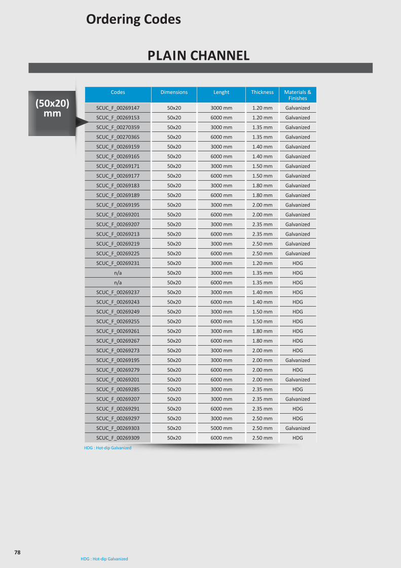
78HDG : Hot-dip Galvanized
PLAIN CHANNEL
Codes Dimensions Lenght Thickness Materials & Finishes
SCUC_F_00269147 50x20 3000 mm 1.20 mm Galvanized
SCUC_F_00269153 50x20 6000 mm 1.20 mm Galvanized
SCUC_F_00270359 50x20 3000 mm 1.35 mm Galvanized
SCUC_F_00270365 50x20 6000 mm 1.35 mm Galvanized
SCUC_F_00269159 50x20 3000 mm 1.40 mm Galvanized
SCUC_F_00269165 50x20 6000 mm 1.40 mm Galvanized
SCUC_F_00269171 50x20 3000 mm 1.50 mm Galvanized
SCUC_F_00269177 50x20 6000 mm 1.50 mm Galvanized
SCUC_F_00269183 50x20 3000 mm 1.80 mm Galvanized
SCUC_F_00269189 50x20 6000 mm 1.80 mm Galvanized
SCUC_F_00269195 50x20 3000 mm 2.00 mm Galvanized
SCUC_F_00269201 50x20 6000 mm 2.00 mm Galvanized
SCUC_F_00269207 50x20 3000 mm 2.35 mm Galvanized
SCUC_F_00269213 50x20 6000 mm 2.35 mm Galvanized
SCUC_F_00269219 50x20 3000 mm 2.50 mm Galvanized
SCUC_F_00269225 50x20 6000 mm 2.50 mm Galvanized
SCUC_F_00269231 50x20 3000 mm 1.20 mm HDG
n/a 50x20 3000 mm 1.35 mm HDG
n/a 50x20 6000 mm 1.35 mm HDG
SCUC_F_00269237 50x20 3000 mm 1.40 mm HDG
SCUC_F_00269243 50x20 6000 mm 1.40 mm HDG
SCUC_F_00269249 50x20 3000 mm 1.50 mm HDG
SCUC_F_00269255 50x20 6000 mm 1.50 mm HDG
SCUC_F_00269261 50x20 3000 mm 1.80 mm HDG
SCUC_F_00269267 50x20 6000 mm 1.80 mm HDG
SCUC_F_00269273 50x20 3000 mm 2.00 mm HDG
SCUC_F_00269195 50x20 3000 mm 2.00 mm Galvanized
SCUC_F_00269279 50x20 6000 mm 2.00 mm HDG
SCUC_F_00269201 50x20 6000 mm 2.00 mm Galvanized
SCUC_F_00269285 50x20 3000 mm 2.35 mm HDG
SCUC_F_00269207 50x20 3000 mm 2.35 mm Galvanized
SCUC_F_00269291 50x20 6000 mm 2.35 mm HDG
SCUC_F_00269297 50x20 3000 mm 2.50 mm HDG
SCUC_F_00269303 50x20 5000 mm 2.50 mm Galvanized
SCUC_F_00269309 50x20 6000 mm 2.50 mm HDG
HDG : Hot-dip Galvanized
(50x20) mm
Ordering Codes
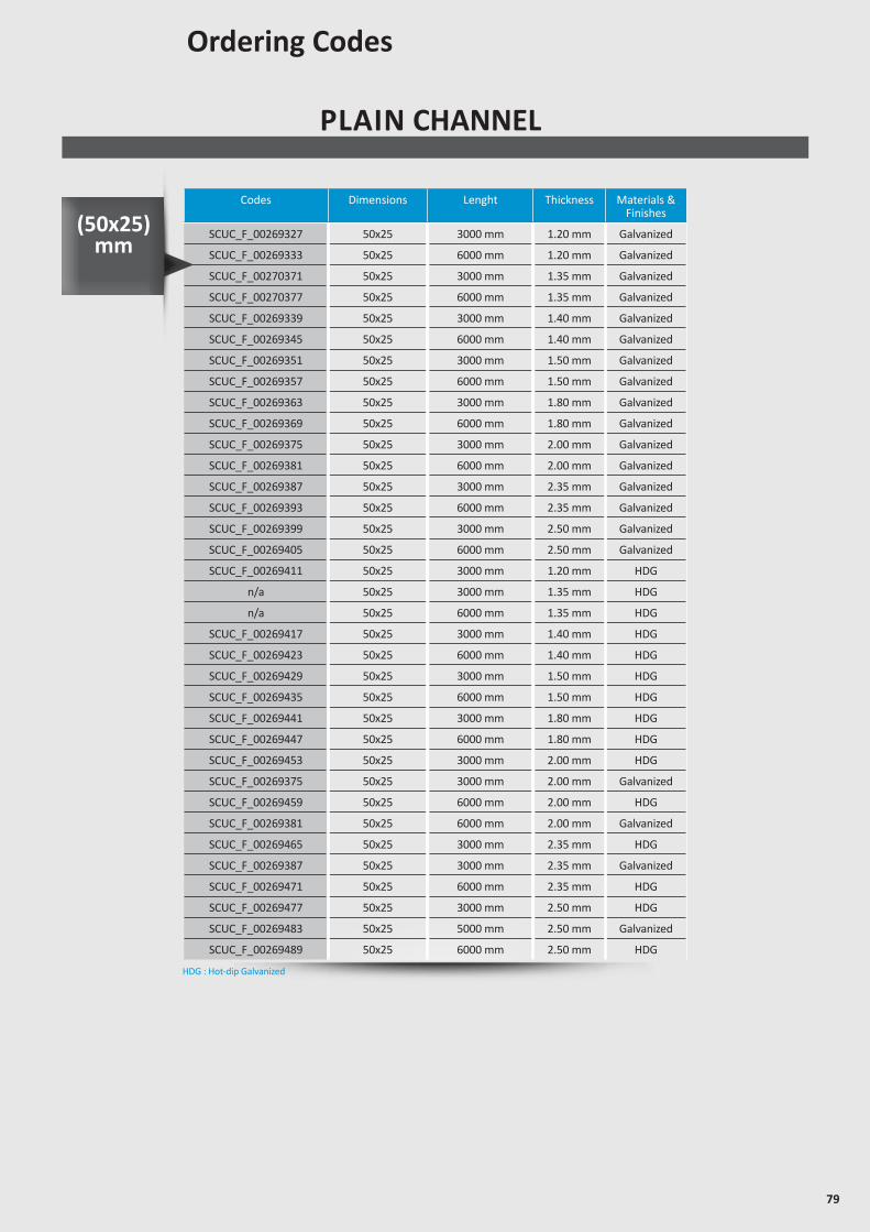
79
PLAIN CHANNEL
Codes Dimensions Lenght Thickness Materials & Finishes
SCUC_F_00269327 50x25 3000 mm 1.20 mm Galvanized
SCUC_F_00269333 50x25 6000 mm 1.20 mm Galvanized
SCUC_F_00270371 50x25 3000 mm 1.35 mm Galvanized
SCUC_F_00270377 50x25 6000 mm 1.35 mm Galvanized
SCUC_F_00269339 50x25 3000 mm 1.40 mm Galvanized
SCUC_F_00269345 50x25 6000 mm 1.40 mm Galvanized
SCUC_F_00269351 50x25 3000 mm 1.50 mm Galvanized
SCUC_F_00269357 50x25 6000 mm 1.50 mm Galvanized
SCUC_F_00269363 50x25 3000 mm 1.80 mm Galvanized
SCUC_F_00269369 50x25 6000 mm 1.80 mm Galvanized
SCUC_F_00269375 50x25 3000 mm 2.00 mm Galvanized
SCUC_F_00269381 50x25 6000 mm 2.00 mm Galvanized
SCUC_F_00269387 50x25 3000 mm 2.35 mm Galvanized
SCUC_F_00269393 50x25 6000 mm 2.35 mm Galvanized
SCUC_F_00269399 50x25 3000 mm 2.50 mm Galvanized
SCUC_F_00269405 50x25 6000 mm 2.50 mm Galvanized
SCUC_F_00269411 50x25 3000 mm 1.20 mm HDG
n/a 50x25 3000 mm 1.35 mm HDG
n/a 50x25 6000 mm 1.35 mm HDG
SCUC_F_00269417 50x25 3000 mm 1.40 mm HDG
SCUC_F_00269423 50x25 6000 mm 1.40 mm HDG
SCUC_F_00269429 50x25 3000 mm 1.50 mm HDG
SCUC_F_00269435 50x25 6000 mm 1.50 mm HDG
SCUC_F_00269441 50x25 3000 mm 1.80 mm HDG
SCUC_F_00269447 50x25 6000 mm 1.80 mm HDG
SCUC_F_00269453 50x25 3000 mm 2.00 mm HDG
SCUC_F_00269375 50x25 3000 mm 2.00 mm Galvanized
SCUC_F_00269459 50x25 6000 mm 2.00 mm HDG
SCUC_F_00269381 50x25 6000 mm 2.00 mm Galvanized
SCUC_F_00269465 50x25 3000 mm 2.35 mm HDG
SCUC_F_00269387 50x25 3000 mm 2.35 mm Galvanized
SCUC_F_00269471 50x25 6000 mm 2.35 mm HDG
SCUC_F_00269477 50x25 3000 mm 2.50 mm HDG
SCUC_F_00269483 50x25 5000 mm 2.50 mm Galvanized
SCUC_F_00269489 50x25 6000 mm 2.50 mm HDG
HDG : Hot-dip Galvanized
(50x25) mm
Ordering Codes
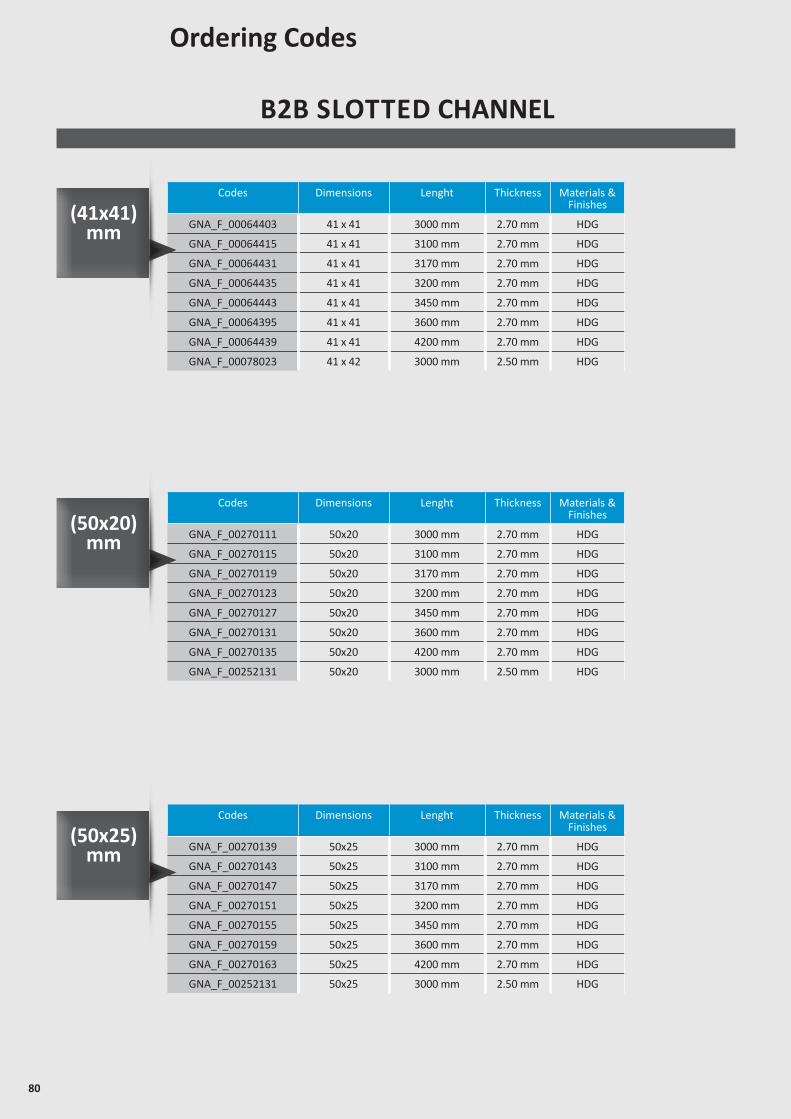
80
B2B SLOTTED CHANNEL
Codes Dimensions Lenght Thickness Materials & Finishes
GNA_F_00064403 41 x 41 3000 mm 2.70 mm HDG
GNA_F_00064415 41 x 41 3100 mm 2.70 mm HDG
GNA_F_00064431 41 x 41 3170 mm 2.70 mm HDG
GNA_F_00064435 41 x 41 3200 mm 2.70 mm HDG
GNA_F_00064443 41 x 41 3450 mm 2.70 mm HDG
GNA_F_00064395 41 x 41 3600 mm 2.70 mm HDG
GNA_F_00064439 41 x 41 4200 mm 2.70 mm HDG
GNA_F_00078023 41 x 42 3000 mm 2.50 mm HDG
Ordering Codes
(41x41) mm
Codes Dimensions Lenght Thickness Materials & Finishes
GNA_F_00270111 50x20 3000 mm 2.70 mm HDG
GNA_F_00270115 50x20 3100 mm 2.70 mm HDG
GNA_F_00270119 50x20 3170 mm 2.70 mm HDG
GNA_F_00270123 50x20 3200 mm 2.70 mm HDG
GNA_F_00270127 50x20 3450 mm 2.70 mm HDG
GNA_F_00270131 50x20 3600 mm 2.70 mm HDG
GNA_F_00270135 50x20 4200 mm 2.70 mm HDG
GNA_F_00252131 50x20 3000 mm 2.50 mm HDG
(50x20) mm
Codes Dimensions Lenght Thickness Materials & Finishes
GNA_F_00270139 50x25 3000 mm 2.70 mm HDG
GNA_F_00270143 50x25 3100 mm 2.70 mm HDG
GNA_F_00270147 50x25 3170 mm 2.70 mm HDG
GNA_F_00270151 50x25 3200 mm 2.70 mm HDG
GNA_F_00270155 50x25 3450 mm 2.70 mm HDG
GNA_F_00270159 50x25 3600 mm 2.70 mm HDG
GNA_F_00270163 50x25 4200 mm 2.70 mm HDG
GNA_F_00252131 50x25 3000 mm 2.50 mm HDG
(50x25) mm
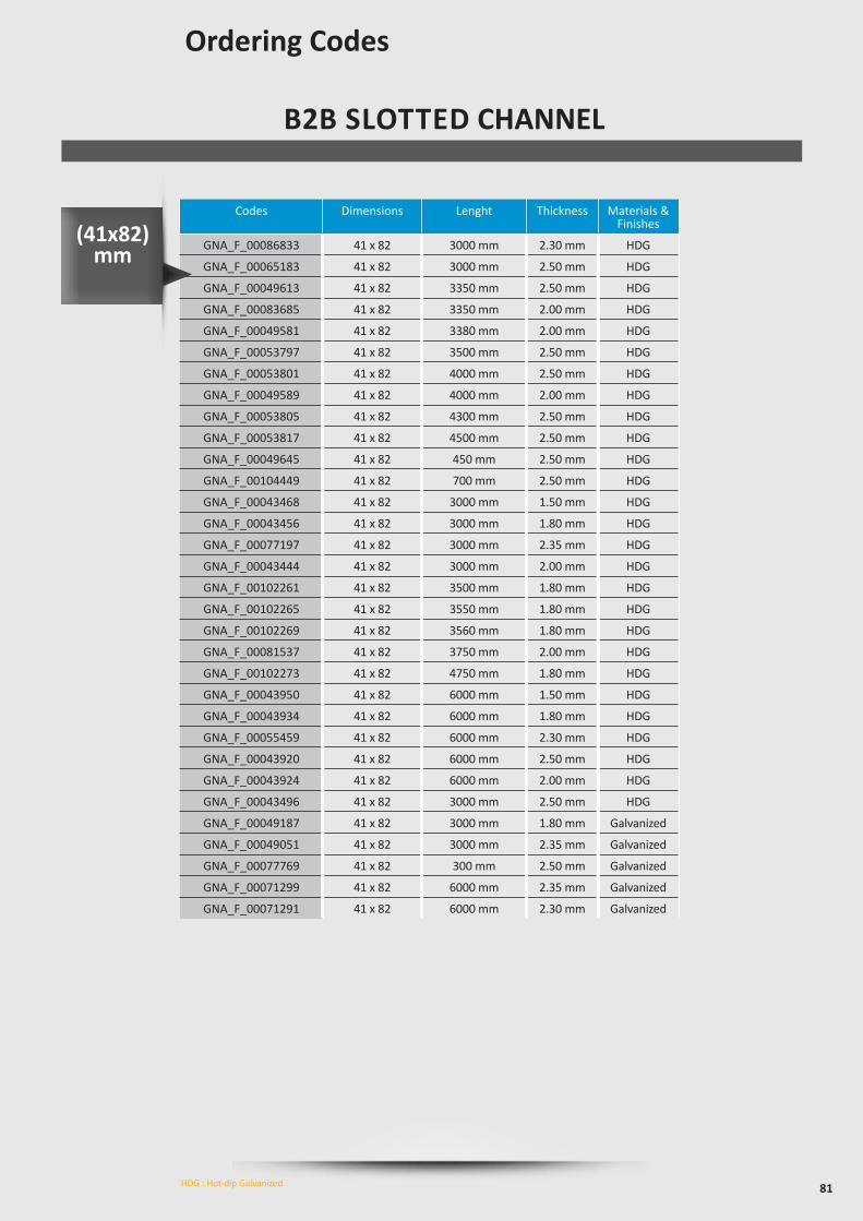
81
B2B SLOTTED CHANNEL
Ordering Codes
HDG : Hot-dip Galvanized
Codes Dimensions Lenght Thickness Materials & Finishes
GNA_F_00086833 41 x 82 3000 mm 2.30 mm HDG
GNA_F_00065183 41 x 82 3000 mm 2.50 mm HDG
GNA_F_00049613 41 x 82 3350 mm 2.50 mm HDG
GNA_F_00083685 41 x 82 3350 mm 2.00 mm HDG
GNA_F_00049581 41 x 82 3380 mm 2.00 mm HDG
GNA_F_00053797 41 x 82 3500 mm 2.50 mm HDG
GNA_F_00053801 41 x 82 4000 mm 2.50 mm HDG
GNA_F_00049589 41 x 82 4000 mm 2.00 mm HDG
GNA_F_00053805 41 x 82 4300 mm 2.50 mm HDG
GNA_F_00053817 41 x 82 4500 mm 2.50 mm HDG
GNA_F_00049645 41 x 82 450 mm 2.50 mm HDG
GNA_F_00104449 41 x 82 700 mm 2.50 mm HDG
GNA_F_00043468 41 x 82 3000 mm 1.50 mm HDG
GNA_F_00043456 41 x 82 3000 mm 1.80 mm HDG
GNA_F_00077197 41 x 82 3000 mm 2.35 mm HDG
GNA_F_00043444 41 x 82 3000 mm 2.00 mm HDG
GNA_F_00102261 41 x 82 3500 mm 1.80 mm HDG
GNA_F_00102265 41 x 82 3550 mm 1.80 mm HDG
GNA_F_00102269 41 x 82 3560 mm 1.80 mm HDG
GNA_F_00081537 41 x 82 3750 mm 2.00 mm HDG
GNA_F_00102273 41 x 82 4750 mm 1.80 mm HDG
GNA_F_00043950 41 x 82 6000 mm 1.50 mm HDG
GNA_F_00043934 41 x 82 6000 mm 1.80 mm HDG
GNA_F_00055459 41 x 82 6000 mm 2.30 mm HDG
GNA_F_00043920 41 x 82 6000 mm 2.50 mm HDG
GNA_F_00043924 41 x 82 6000 mm 2.00 mm HDG
GNA_F_00043496 41 x 82 3000 mm 2.50 mm HDG
GNA_F_00049187 41 x 82 3000 mm 1.80 mm Galvanized
GNA_F_00049051 41 x 82 3000 mm 2.35 mm Galvanized
GNA_F_00077769 41 x 82 300 mm 2.50 mm Galvanized
GNA_F_00071299 41 x 82 6000 mm 2.35 mm Galvanized
GNA_F_00071291 41 x 82 6000 mm 2.30 mm Galvanized
(41x82) mm
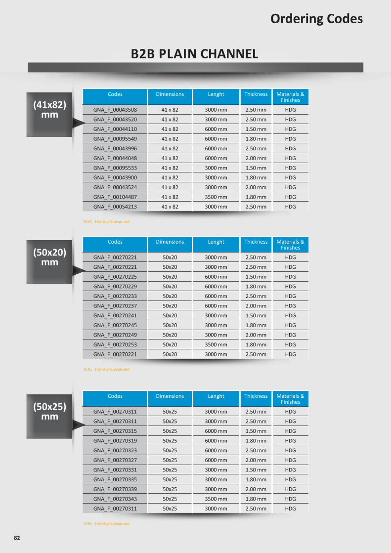
82
B2B PLAIN CHANNEL
Codes Dimensions Lenght Thickness Materials & Finishes
GNA_F_00043508 41 x 82 3000 mm 2.50 mm HDG
GNA_F_00043520 41 x 82 3000 mm 2.50 mm HDG
GNA_F_00044110 41 x 82 6000 mm 1.50 mm HDG
GNA_F_00095549 41 x 82 6000 mm 1.80 mm HDG
GNA_F_00043996 41 x 82 6000 mm 2.50 mm HDG
GNA_F_00044048 41 x 82 6000 mm 2.00 mm HDG
GNA_F_00095533 41 x 82 3000 mm 1.50 mm HDG
GNA_F_00043900 41 x 82 3000 mm 1.80 mm HDG
GNA_F_00043524 41 x 82 3000 mm 2.00 mm HDG
GNA_F_00104487 41 x 82 3500 mm 1.80 mm HDG
GNA_F_00054213 41 x 82 3000 mm 2.50 mm HDG
Codes Dimensions Lenght Thickness Materials & Finishes
GNA_F_00270221 50x20 3000 mm 2.50 mm HDG
GNA_F_00270221 50x20 3000 mm 2.50 mm HDG
GNA_F_00270225 50x20 6000 mm 1.50 mm HDG
GNA_F_00270229 50x20 6000 mm 1.80 mm HDG
GNA_F_00270233 50x20 6000 mm 2.50 mm HDG
GNA_F_00270237 50x20 6000 mm 2.00 mm HDG
GNA_F_00270241 50x20 3000 mm 1.50 mm HDG
GNA_F_00270245 50x20 3000 mm 1.80 mm HDG
GNA_F_00270249 50x20 3000 mm 2.00 mm HDG
GNA_F_00270253 50x20 3500 mm 1.80 mm HDG
GNA_F_00270221 50x20 3000 mm 2.50 mm HDG
Codes Dimensions Lenght Thickness Materials & Finishes
GNA_F_00270311 50x25 3000 mm 2.50 mm HDG
GNA_F_00270311 50x25 3000 mm 2.50 mm HDG
GNA_F_00270315 50x25 6000 mm 1.50 mm HDG
GNA_F_00270319 50x25 6000 mm 1.80 mm HDG
GNA_F_00270323 50x25 6000 mm 2.50 mm HDG
GNA_F_00270327 50x25 6000 mm 2.00 mm HDG
GNA_F_00270331 50x25 3000 mm 1.50 mm HDG
GNA_F_00270335 50x25 3000 mm 1.80 mm HDG
GNA_F_00270339 50x25 3000 mm 2.00 mm HDG
GNA_F_00270343 50x25 3500 mm 1.80 mm HDG
GNA_F_00270311 50x25 3000 mm 2.50 mm HDG
Ordering Codes
HDG : Hot-dip Galvanized
HDG : Hot-dip Galvanized
HDG : Hot-dip Galvanized
(41x82) mm
(50x20) mm
(50x25) mm
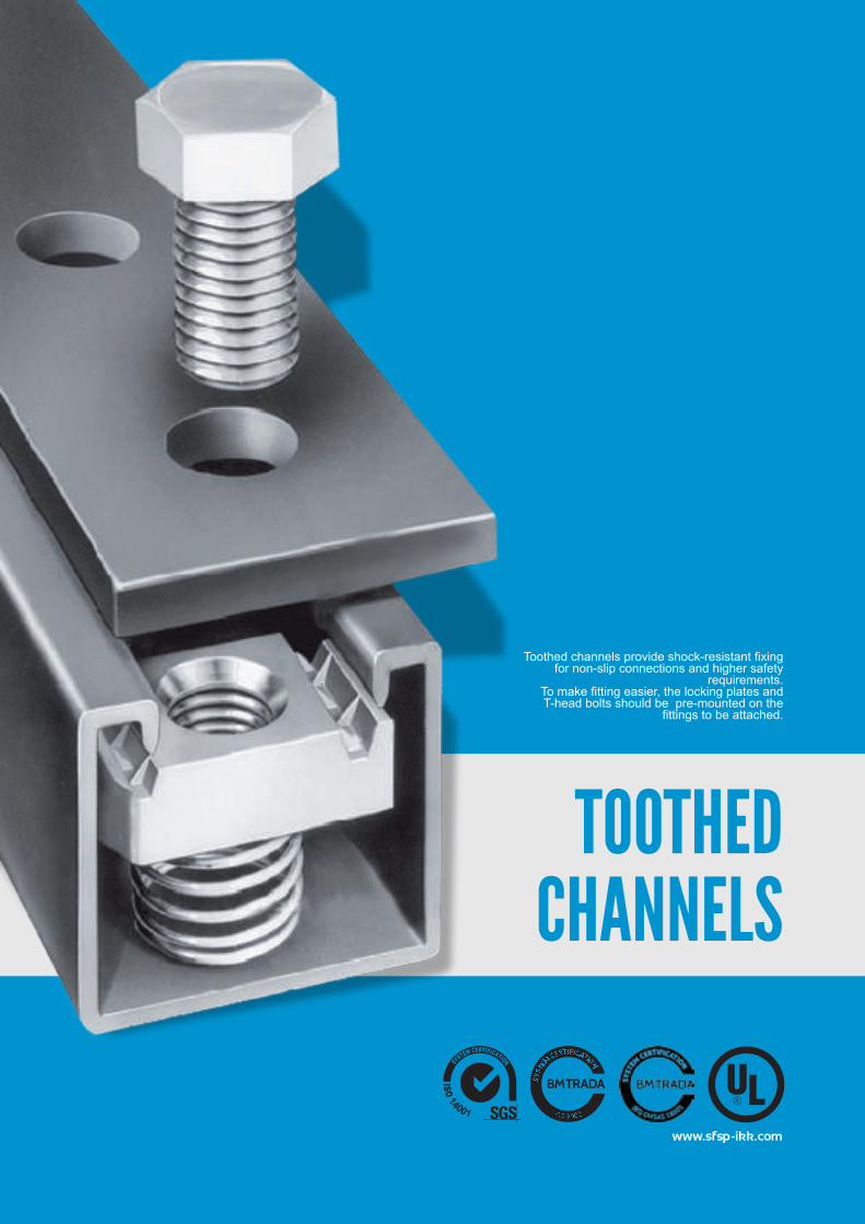
www.sfsp-ikk.com
Toothed channels provide shock-resistant fixing for non-slip connections and higher safety
requirements.To make fitting easier, the locking plates and T-head bolts should be pre-mounted on the
fittings to be attached.
TOOTHED CHANNELS
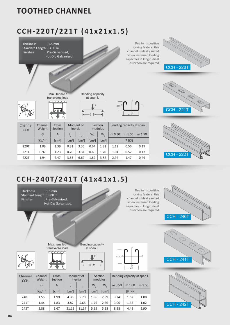
84
TOOTHED CHANNEL
C C H - 2 2 0 T/ 2 2 1 T ( 4 1 x 2 1 x 1 . 5 )
Z
Z
YY21.0
41.0
Z
Z
YY41.0
41.0
Due to its positive locking feature, this
channel is ideally suited when increased loading
capacities in longitudinal.direction are required
ChannelCCH
ChannelWeight
CrossSection
Moment ofinertia
Sectionmodulus
Bending capacity at span L
G A Iy Iz Wy Wz m 0.50 m 1.00 m 1.50
[Kg/m] [cm2] [cm4] [cm4] [cm3] [cm3] [F [KN
220T 1.09 1.39 0.81 3.36 0.64 1.91 1.12 0.56 0.19
221T 0.97 1.23 0.70 3.34 0.60 1.70 1.04 0.52 0.17
222T 1.94 2.47 3.55 6.69 1.69 3.82 2.94 1.47 0.49
Max. tensile /transverse load
FZ FQ
F
]L ]m
Bending capacityat span L
Z
Z
Y
YX
ChannelCCH
ChannelWeight
CrossSection
Moment ofinertia
Sectionmodulus
Bending capacity at span L
G A Iy Iz Wy Wz m 0.50 m 1.00 m 1.50
[Kg/m] [cm2] [cm4] [cm4] [cm3] [cm3] [F [KN
240T 1.56 1.99 4.36 5.70 1.86 2.99 3.24 1.62 1.08
241T 1.44 1.83 3.87 5.68 1.76 2.66 3.06 1.53 1.02
242T 2.88 3.67 21.11 11.37 5.15 5.98 8.98 4.49 2.90
Z
Z
YY21.0
41.0
Z
Z
YY41.0
41.0
Due to its positive locking feature, this
channel is ideally suited when increased loading
capacities in longitudinal.direction are required
Max. tensile /transverse load
FZ FQ
F
]L ]m
Bending capacityat span L
Z
Z
Y
YX
C C H - 2 4 0 T/ 2 4 1 T ( 4 1 x 4 1 x 1 . 5 )
CCH - 241T
CCH - 240T
CCH - 242T
CCH - 221T
CCH - 220T
CCH - 222T
Thickness : 1.5 mmStandard Length : 3.00 m Finishes : Pre-Galvanized, Hot-Dip Galvanized.
Thickness : 1.5 mmStandard Length : 3.00 m Finishes : Pre-Galvanized, Hot-Dip Galvanized.
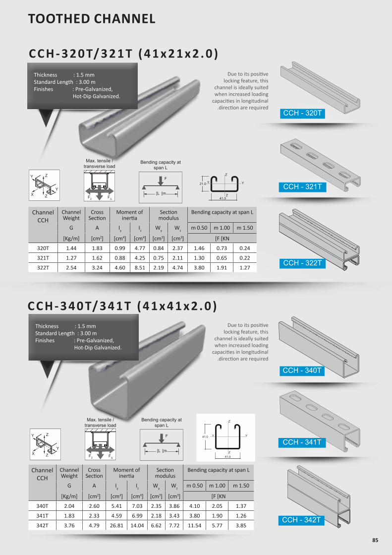
85
ChannelCCH
ChannelWeight
CrossSection
Moment ofinertia
Sectionmodulus
Bending capacity at span L
G A Iy Iz Wy Wz m 0.50 m 1.00 m 1.50
[Kg/m] [cm2] [cm4] [cm4] [cm3] [cm3] [F [KN
340T 2.04 2.60 5.41 7.03 2.35 3.86 4.10 2.05 1.37
341T 1.83 2.33 4.59 6.99 2.18 3.43 3.80 1.90 1.26
342T 3.76 4.79 26.81 14.04 6.62 7.72 11.54 5.77 3.85
ChannelCCH
ChannelWeight
CrossSection
Moment ofinertia
Sectionmodulus
Bending capacity at span L
G A Iy Iz Wy Wz m 0.50 m 1.00 m 1.50
[Kg/m] [cm2] [cm4] [cm4] [cm3] [cm3] [F [KN
320T 1.44 1.83 0.99 4.77 0.84 2.37 1.46 0.73 0.24
321T 1.27 1.62 0.88 4.25 0.75 2.11 1.30 0.65 0.22
322T 2.54 3.24 4.60 8.51 2.19 4.74 3.80 1.91 1.27
TOOTHED CHANNEL
Z
Z
YY21.0
41.0
Z
Z
YY41.0
41.0
Max. tensile /transverse load
FZ FQ
F
]L ]m
Bending capacity atspan L
Z
Z
YY21.0
41.0
Z
Z
YY41.0
41.0
Max. tensile /transverse load
FZ FQ
F
]L ]m
Bending capacity atspan L
Z
Z
Y
YX
Z
Z
Y
YX
Due to its positive locking feature, this
channel is ideally suited when increased loading
capacities in longitudinal.direction are required
CCH - 321T
CCH - 341T
CCH - 320T
CCH - 340T
CCH - 322T
CCH - 342T
C C H - 3 2 0 T/ 3 2 1 T ( 4 1 x 2 1 x 2 . 0 )
C C H - 3 4 0 T/ 3 4 1 T ( 4 1 x 4 1 x 2 . 0 )
Thickness : 1.5 mmStandard Length : 3.00 m Finishes : Pre-Galvanized, Hot-Dip Galvanized.
Thickness : 1.5 mmStandard Length : 3.00 m Finishes : Pre-Galvanized, Hot-Dip Galvanized.
Due to its positive locking feature, this
channel is ideally suited when increased loading
capacities in longitudinal.direction are required
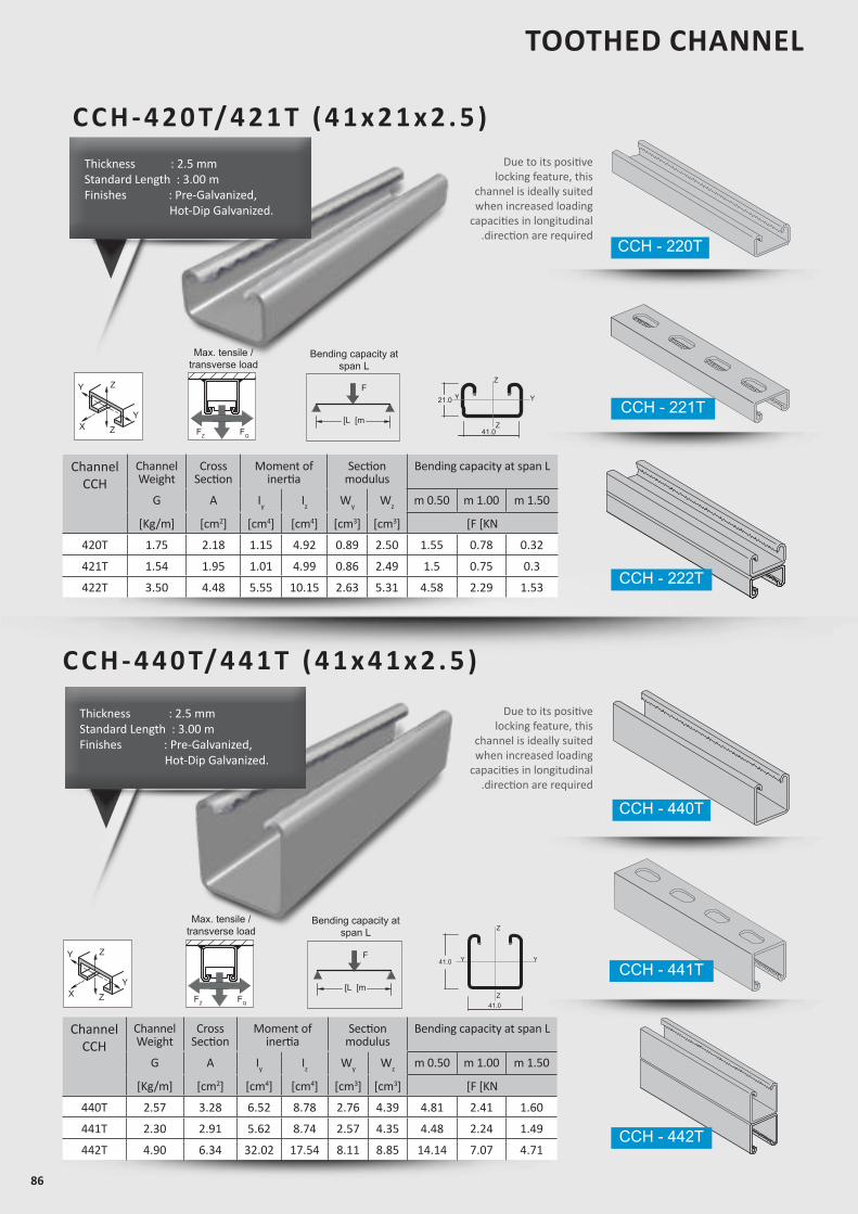
86
Due to its positive locking feature, this
channel is ideally suited when increased loading
capacities in longitudinal.direction are required
Due to its positive locking feature, this
channel is ideally suited when increased loading
capacities in longitudinal.direction are required
Thickness : 2.5 mmStandard Length : 3.00 m Finishes : Pre-Galvanized, Hot-Dip Galvanized.
Thickness : 2.5 mmStandard Length : 3.00 m Finishes : Pre-Galvanized, Hot-Dip Galvanized.
C C H - 4 2 0 T/ 4 2 1 T ( 4 1 x 2 1 x 2 . 5 )
Z
Z
YY21.0
41.0
Z
Z
YY41.0
41.0
ChannelCCH
ChannelWeight
CrossSection
Moment ofinertia
Sectionmodulus
Bending capacity at span L
G A Iy Iz Wy Wz m 0.50 m 1.00 m 1.50
[Kg/m] [cm2] [cm4] [cm4] [cm3] [cm3] [F [KN
420T 1.75 2.18 1.15 4.92 0.89 2.50 1.55 0.78 0.32
421T 1.54 1.95 1.01 4.99 0.86 2.49 1.5 0.75 0.3
422T 3.50 4.48 5.55 10.15 2.63 5.31 4.58 2.29 1.53
Max. tensile /transverse load
FZ FQ
F
]L ]m
Bending capacity atspan L
Z
Z
Y
YX
CCH - 221T
CCH - 220T
CCH - 222T
TOOTHED CHANNEL
C C H - 4 4 0 T/ 4 4 1 T ( 4 1 x 4 1 x 2 . 5 )
Z
Z
YY21.0
41.0
Z
Z
YY41.0
41.0
ChannelCCH
ChannelWeight
CrossSection
Moment ofinertia
Sectionmodulus
Bending capacity at span L
G A Iy Iz Wy Wz m 0.50 m 1.00 m 1.50
[Kg/m] [cm2] [cm4] [cm4] [cm3] [cm3] [F [KN
440T 2.57 3.28 6.52 8.78 2.76 4.39 4.81 2.41 1.60
441T 2.30 2.91 5.62 8.74 2.57 4.35 4.48 2.24 1.49
442T 4.90 6.34 32.02 17.54 8.11 8.85 14.14 7.07 4.71
Max. tensile /transverse load
FZ FQ
F
]L ]m
Bending capacity atspan L
Z
Z
Y
YX
CCH - 441T
CCH - 440T
CCH - 442T
www.sfsp-ikk.com
FITTINGS
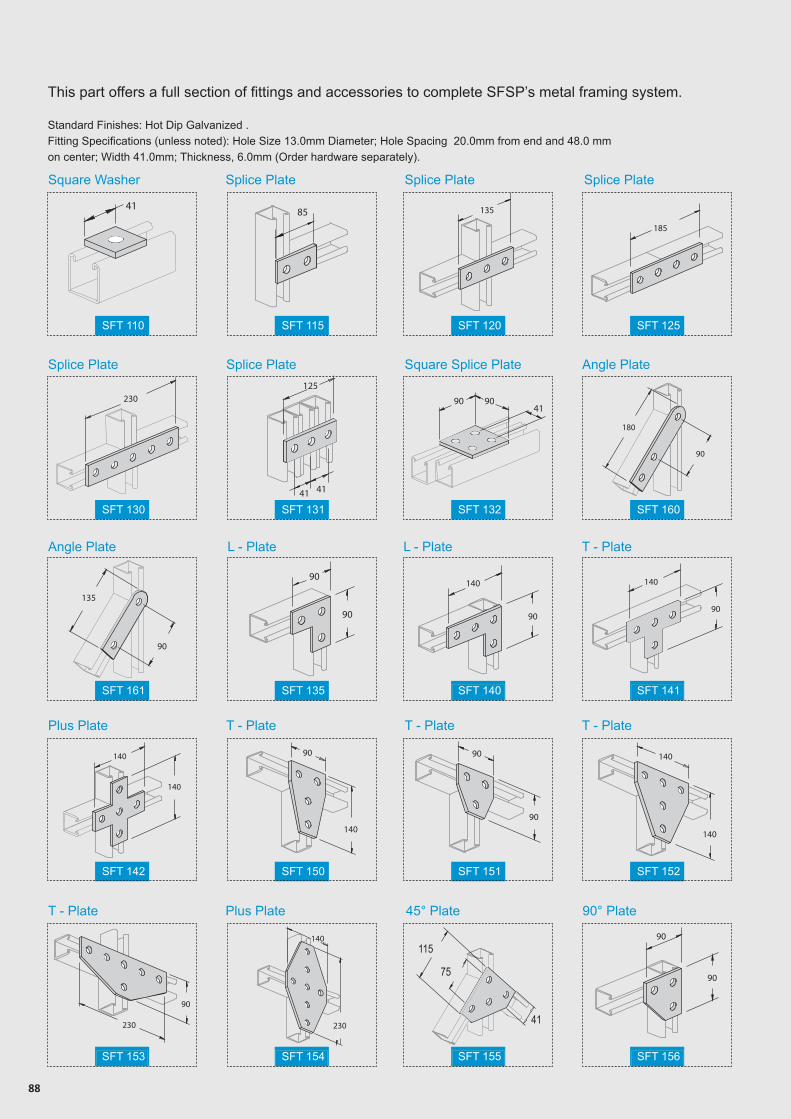
88
SFT 153 SFT 154 SFT 155 SFT 156
SFT 142 SFT 150 SFT 151 SFT 152
SFT 161 SFT 135 SFT 140 SFT 141
SFT 130 SFT 131 SFT 132 SFT 160
SFT 110 SFT 115 SFT 120 SFT 125
L - Plate
This part offers a full section of fittings and accessories to complete SFSP’s metal framing system.
Standard Finishes: Hot Dip Galvanized .Fitting Specifications (unless noted): Hole Size 13.0mm Diameter; Hole Spacing 20.0mm from end and 48.0 mm on center; Width 41.0mm; Thickness, 6.0mm (Order hardware separately).
Square Washer Splice Plate Splice Plate Splice Plate
Splice Plate Splice Plate Square Splice Plate Angle Plate
Angle Plate L - Plate T - Plate
T - PlateT - PlateT - Plate
T - Plate
Plus Plate
Plus Plate 45° Plate 90° Plate
41 85 135
185
230
125
4141
9041
90
180
90
135
90
90
90
140
90
90
140
140
140
140
90
90
90
140
140
90
230
140
230
115
75
41
90
90
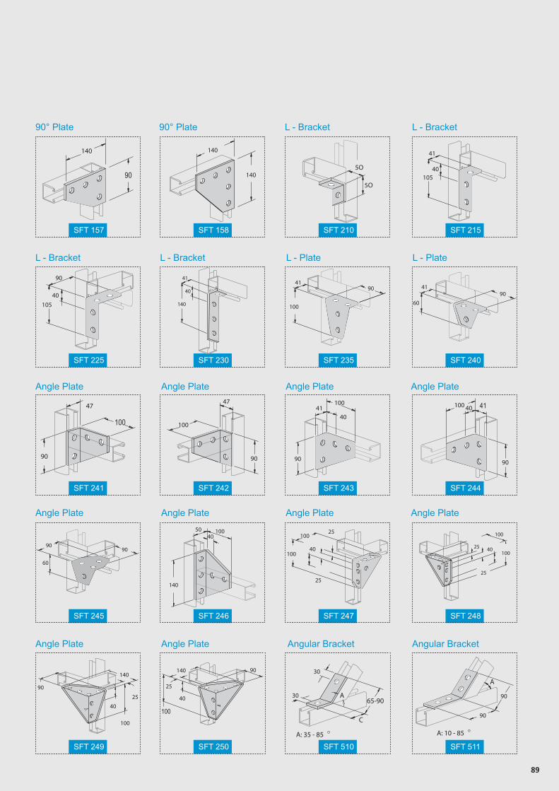
89
SFT 157 SFT 158 SFT 210 SFT 215
SFT 225 SFT 230 SFT 235 SFT 240
SFT 241 SFT 242 SFT 243 SFT 244
SFT 245 SFT 246 SFT 247 SFT 248
SFT 249 SFT 250 SFT 510 SFT 511
41
40
140
90° Plate 90° Plate L - Bracket
L - Bracket
Angle Plate
Angle Plate
Angle Plate
Angle Plate
Angle Plate
Angle Plate
Angle Plate
Angle Plate Angular Bracket Angular Bracket
Angle Plate
Angle Plate
L - Bracket
L - Bracket L - Plate L - Plate
140
90
140
1405O
5O
41
40105
90
40105
41
100
9090
60
41
47
100
90
47
100
90
10041
90
40
100 40 41
90
60
9090
140
50 10040
25
25
40100
100
25
25
40100
100
140
90
40
100
25
25
140 90
40
100
3065-90
C
A
OA: 35 - 85
30
A
90
90
OA: 10 - 85
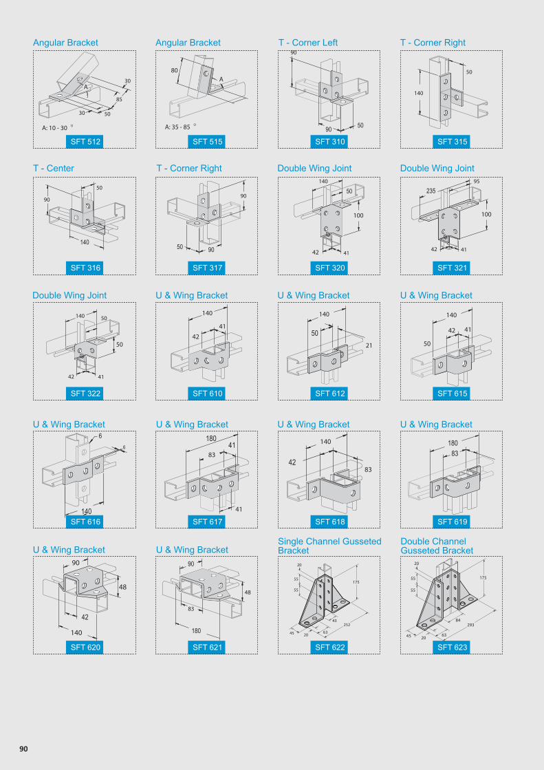
90
Angular Bracket
T - Center T - Corner Right Double Wing Joint
Double Wing Joint U & Wing Bracket
U & Wing Bracket
Single Channel Gusseted Bracket
Double Channel Gusseted Bracket
U & Wing Bracket U & Wing Bracket U & Wing Bracket
U & Wing Bracket U & Wing Bracket
Double Wing Joint
Angular Bracket T - Corner Left T - Corner Right
SFT 512
SFT 316
SFT 322
SFT 616
SFT 620
SFT 515
SFT 317
SFT 610
SFT 617
SFT 621
SFT 310
SFT 320
SFT 612
SFT 618
SFT 622
SFT 315
SFT 321
SFT 615
SFT 619
SFT 623
A30
30
85
50
OA: 10 - 30
A80
OA: 35 - 85
90
90 50
50
140
50
140
9090
9050
100
140
4142
50
41
100
23595
42
50
140
4142
50140
42
41
140
21
50
140
4142
50
140
6
6
180
8341
41
140
8342
18083
140
90
42
48
180
90
83
48
175
252
45 6320
43
55
20
55
175
45 6320
55
20
55
84293
U & Wing Bracket U & Wing Bracket
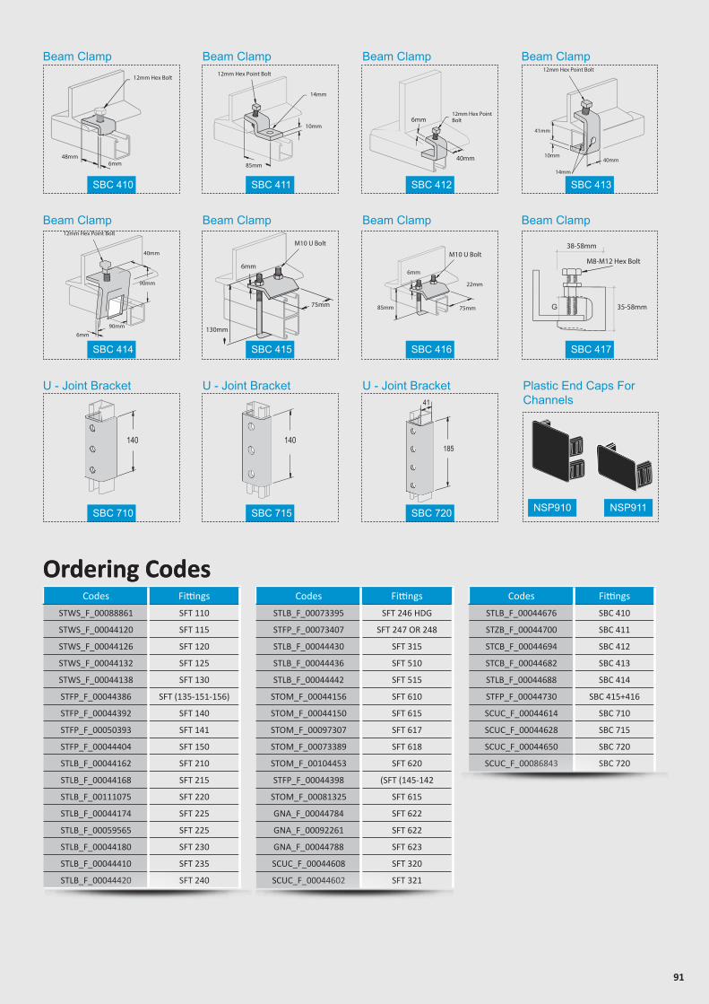
91
Codes Fittings
STWS_F_00088861 SFT 110
STWS_F_00044120 SFT 115
STWS_F_00044126 SFT 120
STWS_F_00044132 SFT 125
STWS_F_00044138 SFT 130
STFP_F_00044386 SFT (135-151-156)
STFP_F_00044392 SFT 140
STFP_F_00050393 SFT 141
STFP_F_00044404 SFT 150
STLB_F_00044162 SFT 210
STLB_F_00044168 SFT 215
STLB_F_00111075 SFT 220
STLB_F_00044174 SFT 225
STLB_F_00059565 SFT 225
STLB_F_00044180 SFT 230
STLB_F_00044410 SFT 235
STLB_F_00044420 SFT 240
Codes Fittings
STLB_F_00044676 SBC 410
STZB_F_00044700 SBC 411
STCB_F_00044694 SBC 412
STCB_F_00044682 SBC 413
STLB_F_00044688 SBC 414
STFP_F_00044730 SBC 415+416
SCUC_F_00044614 SBC 710
SCUC_F_00044628 SBC 715
SCUC_F_00044650 SBC 720
SCUC_F_00086843 SBC 720
Codes Fittings
STLB_F_00073395 SFT 246 HDG
STFP_F_00073407 SFT 247 OR 248
STLB_F_00044430 SFT 315
STLB_F_00044436 SFT 510
STLB_F_00044442 SFT 515
STOM_F_00044156 SFT 610
STOM_F_00044150 SFT 615
STOM_F_00097307 SFT 617
STOM_F_00073389 SFT 618
STOM_F_00104453 SFT 620
STFP_F_00044398 (SFT (145-142
STOM_F_00081325 SFT 615
GNA_F_00044784 SFT 622
GNA_F_00092261 SFT 622
GNA_F_00044788 SFT 623
SCUC_F_00044608 SFT 320
SCUC_F_00044602 SFT 321
Ordering Codes
Beam Clamp
Beam Clamp
U - Joint Bracket U - Joint Bracket U - Joint Bracket Plastic End Caps For Channels
Beam Clamp
Beam Clamp
Beam Clamp
Beam Clamp
Beam Clamp
Beam Clamp
48mm6mm
12mm Hex Bolt
85mm
10mm
14mm
12mm Hex Point Bolt
41mm
10mm
14mm
40mm
12mm Hex Point Bolt
6mm90mm
90mm
40mm
12mm Hex Point Bolt
6mm
75mm
130mm
M10 U Bolt
75mm
22mm
85mm
6mm
M10 U BoltM8-M12 Hex Bolt
38-58mm
35-58mm
140 140185
41
SBC 710 SBC 720 NSP910 NSP911SBC 715
SBC 414 SBC 416SBC 415 SBC 417
SBC 410 SBC 412SBC 411 SBC 413
40mm
6mm12mm Hex PointBolt
Ordering Codes
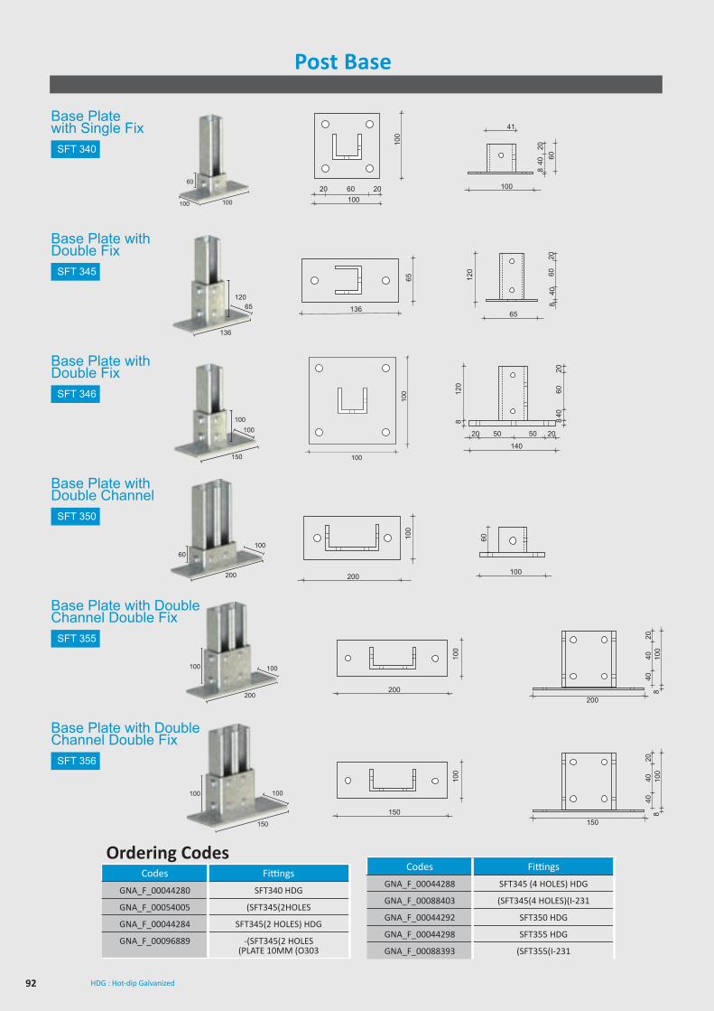
92 HDG : Hot-dip Galvanized
200
100
150
100
200
100
4040
820
150
100
4040
820
Post Base
Codes Fittings
GNA_F_00044280 SFT340 HDG
GNA_F_00054005 (SFT345(2HOLES
GNA_F_00044284 SFT345(2 HOLES) HDG
GNA_F_00096889 -(SFT345(2 HOLES(PLATE 10MM (O303
Codes Fittings
GNA_F_00044288 SFT345 (4 HOLES) HDG
GNA_F_00088403 (SFT345(4 HOLES)(I-231
GNA_F_00044292 SFT350 HDG
GNA_F_00044298 SFT355 HDG
GNA_F_00088393 (SFT355(I-231
Ordering Codes
SFT 340
SFT 345
SFT 346
SFT 350
SFT 355
SFT 356
20 2060100
100
100
41
408
6020
Base Plate with Single Fix
Base Plate with Double Fix
Base Plate with Double Fix
Base Plate with Double Channel
Base Plate with Double Channel Double Fix
Base Plate with Double Channel Double Fix
60
100100
136
65
65
120 60
2040
8
100150
100100
100
140
50 50 2020
120
8
6040
208
136
12065
200
100
100
60
200
60100
100100
200
100100
150
www.sfsp-ikk.com
ACCESSORIES
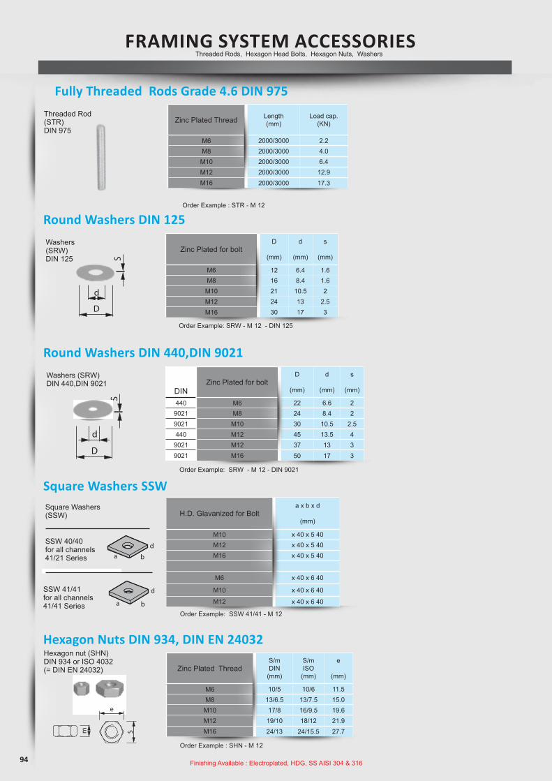
94
Zinc Plated for boltD
(mm)
d
(mm)
s
(mm)
M6 12 6.4 1.6M8 16 8.4 1.6
M10 21 10.5 2M12 24 13 2.5M16 30 17 3
Hexagon Nuts DIN 934, DIN EN 24032
S
m
S
d
D
S
d
D
Zinc PlatedThread - ZP
Zinc Platedfor bolt - ZP
Zinc PlatedDimension- ZP
D
[mm]
D
[mm]
S/mDIN
[mm]
SDIN
[mm]
S/mISO
[mm]
SEN
[mm]
e
[mm]
d
[mm]
d
[mm]
s
[mm]
s
[mm]
Length
[mm]
Load
cap.
[kN]
Threaded Rods, Hexagon Head Bol ts, Nuts, Washers
FR AMI NG SY STEM S ACC ESSORI ES
Order Example : TR - ZP - M 12 × 1000
Order Example : HB - ZP - M 12 × 1000
Order Example: WA - ZP - M 12 - DIN 9021
Order Example: WA - ZP - M 12 - DIN 125
DIN
22
24
30
45
37
50
12
16
21
24
30
10/ 5
13/6,5
17/ 8
19/10
24/13
10
13
17
19
24
18
24
10
13
16
10/ 6
13/7,5
16/ 9,5
18/12
24/15,5
11,5
15,0
19,6
21,9
27,7
6,6
8,4
10,5
13,5
13
17
6,4
8,4
10,5
13
17
2
2
2,5
4
3
3
1,6
1,6
2
2,5
3
1000
1000
1000
1000
1000
2,2
4,0
6,4
12,9
17,3
M 6
M 8
M 10
M 12
M 16
M 6 x 12
M 6 x 25
M 8 x 25
M 8 x 40
M 10 x 20
M 10 x 30
M 10 x 45
M 10 x 60
M 10 x 70
M 12 x 22
M 12 x 25
M 12 x 30
M 12 x 40
M 12 x 50
M 12 x 60
M 12 x 80
M 12 x 90
M 16 x 40
M 16 x 60
M 16 x 90
M 8 x 25
M 10 x 30
M 10 x 45
M 12 x 25
M 12 x 30
M 12 x 40
M 12 x 60
M 12 x 80
M 16 x 40
M 16 x 60
M 16 x 90
M 6
M 8
M 10
M 12
M 16
M 6
M 8
M 10
M 12
M 16
440
9021
9021
440
9021
9021
M 6
M 8
M 10
M 12
M 12
M 16
M 6
M 8
M 10
M 12
M 16
M 8
M 10
M 12
M 16
M 6
M 8
M 10
M 12
M 16
M 6
M 8
M 10
M 12
M 16
Stainless SteelThread
Zinc PlatedThread - ZP
Stainless SteelThread
Stainless Steelfor bolt
Zinc Platedfor bolt - ZP
Stainless Steelfor bolt
Stainless SteelDimension
Material & Finishes Codes
( S. 53)
= h.d. galvanised, strength grade 4.6
= electroplated, 4.6
= , 8.8
= Stainless steel grade A4-50
strength grade
h.d. galvanised strength grade
= electroplated, strength grade 8.8
= Stainless steel grade A4-70
= Stainless steel grade A2-50
= Stainless steel grade A2-70
= Stainless steel W1.4529 HCR-50
fv
gv
fv 8.8
A4-50
gv 8.8
A4-70
A2-50
A2-70
HCR
e
S
Hexagon nut (SHN)DIN 934 or ISO 4032(= DIN EN 24032) Zinc Plated Thread
S/mDIN
(mm)
S/mISO
(mm)
e
(mm)
M6 10/5 10/6 11.5M8 13/6.5 13/7.5 15.0
M10 17/8 16/9.5 19.6M12 19/10 18/12 21.9M16 24/13 24/15.5 27.7
Order Example : SHN - M 12
Finishing Available : Electroplated, HDG, SS AISI 304 & 316
DINZinc Plated for bolt
D
(mm)
d
(mm)
s
(mm)
440 M6 22 6.6 29021 M8 24 8.4 29021 M10 30 10.5 2.5440 M12 45 13.5 4
9021 M12 37 13 39021 M16 50 17 3
Fully Threaded Rods Grade 4.6 DIN 975S
m
S
d
D
S
d
D
Zinc PlatedThread - ZP
Zinc Platedfor bolt - ZP
Zinc PlatedDimension- ZP
D
[mm]
D
[mm]
S/mDIN
[mm]
SDIN
[mm]
S/mISO
[mm]
SEN
[mm]
e
[mm]
d
[mm]
d
[mm]
s
[mm]
s
[mm]
Length
[mm]
Load
cap.
[kN]
Threaded Rods, Hexagon Head Bol ts, Nuts, Washers
FR AMI NG SY STEM S ACC ESSORI ES
Order Example : TR - ZP - M 12 × 1000
Order Example : HB - ZP - M 12 × 1000
Order Example: WA - ZP - M 12 - DIN 9021
Order Example: WA - ZP - M 12 - DIN 125
DIN
22
24
30
45
37
50
12
16
21
24
30
10/ 5
13/6,5
17/ 8
19/10
24/13
10
13
17
19
24
18
24
10
13
16
10/ 6
13/7,5
16/ 9,5
18/12
24/15,5
11,5
15,0
19,6
21,9
27,7
6,6
8,4
10,5
13,5
13
17
6,4
8,4
10,5
13
17
2
2
2,5
4
3
3
1,6
1,6
2
2,5
3
1000
1000
1000
1000
1000
2,2
4,0
6,4
12,9
17,3
M 6
M 8
M 10
M 12
M 16
M 6 x 12
M 6 x 25
M 8 x 25
M 8 x 40
M 10 x 20
M 10 x 30
M 10 x 45
M 10 x 60
M 10 x 70
M 12 x 22
M 12 x 25
M 12 x 30
M 12 x 40
M 12 x 50
M 12 x 60
M 12 x 80
M 12 x 90
M 16 x 40
M 16 x 60
M 16 x 90
M 8 x 25
M 10 x 30
M 10 x 45
M 12 x 25
M 12 x 30
M 12 x 40
M 12 x 60
M 12 x 80
M 16 x 40
M 16 x 60
M 16 x 90
M 6
M 8
M 10
M 12
M 16
M 6
M 8
M 10
M 12
M 16
440
9021
9021
440
9021
9021
M 6
M 8
M 10
M 12
M 12
M 16
M 6
M 8
M 10
M 12
M 16
M 8
M 10
M 12
M 16
M 6
M 8
M 10
M 12
M 16
M 6
M 8
M 10
M 12
M 16
Stainless SteelThread
Zinc PlatedThread - ZP
Stainless SteelThread
Stainless Steelfor bolt
Zinc Platedfor bolt - ZP
Stainless Steelfor bolt
Stainless SteelDimension
Material & Finishes Codes
( S. 53)
= h.d. galvanised, strength grade 4.6
= electroplated, 4.6
= , 8.8
= Stainless steel grade A4-50
strength grade
h.d. galvanised strength grade
= electroplated, strength grade 8.8
= Stainless steel grade A4-70
= Stainless steel grade A2-50
= Stainless steel grade A2-70
= Stainless steel W1.4529 HCR-50
fv
gv
fv 8.8
A4-50
gv 8.8
A4-70
A2-50
A2-70
HCR
e
SZinc Plated Thread Length
(mm)Load cap.
(KN)
M6 2000/3000 2.2M8 2000/3000 4.0
M10 2000/3000 6.4M12 2000/3000 12.9M16 2000/3000 17.3
Order Example : STR - M 12
Threaded Rod (STR)DIN 975
Square Washers SSW
H.D. Glavanized for Bolta x b x d
(mm)
M10 x 40 x 5 40M12 x 40 x 5 40M16 x 40 x 5 40
M6 x 40 x 6 40
M10 x 40 x 6 40
M12 x 40 x 6 40
FR AMI NG SY STEM S ACC ESSORI ES
s
L
D
L
Loadcap.
[kN]
Order example:
Order example:
Loadcap.
[kN]
S
[mm]
L
[mm]
D
[mm]
L
[mm]
10/10
12/14
13/16
16/20
21/25
26/32
13
17
22
15
20
25
30
40
50
40
40
50
2,2
4,0
6,4
9,3
17,3
27,0
6,4
9,3
17,3
M 6
M 8
M 10
M 12
M 16
M 20
M 10
M 12
M 16
M 6
M 8
M 10
M 12
M 16
M 20
M 10
M 12
M 16
CS - GV - M 16
HRC - GV - M 12
Coupler Sleeves, Square washers ,Sleeve Anchor ,Throught Anchor .......
Throught Anchor
Sleeve Anchor
b
da
b
d
a
Order Example: SW 41/41 - HDG - M 12
40 x 40 x 5
40 x 40 x 5
40 x 40 x 5
40 x 40 x 6
40 x 40 x 6
40 x 40 x 6
a x b x d
[mm]
M 10
M 12
M 16
M 6
M 10
M 12
M 6
M 10
M 12
M 10
M 12
M 16
ElectroplatedThread - GV
ElectroplatedThread - GV
Stainless SteelThread
Stainless SteelThread
H.D. Galvanisedfor Bolts - HDG
Stainless Steelfor Bolts
Yellow zinc plated SteelThread (Zn)
L (mm)
Order example:
M 6
M 8
M 10
M 12
45
50
60
74
M 6
M 8
M 10
STM - Zn - M 12
Stainless Steel
Thread
Drill
(mm)
10
12
15
18
Min.Drill hole
(mm)
55
60
75
90
M 6
M 8
M 10
Stainless Steel
Thread
Yellow zinc plated SteelThread (Zn)
Screwx Length (mm)
Order example:
M 6
M 8
M 10
M 12
6x50
8x60
10x80
12x90
STMH - Zn - M 12
S max fixing(mm)
5
10
20
25
Yellow zinc plated Steel Thread (Zn)
10
25
45
75
10.3
12.2
17.1
25.3
9.6
17.5
27.8
40.5
M 6
M 8
M 10
M 12
TypeMax Torque
(mm)Pull Out
Shear
8
19
38
9.5
14
19
8.4
15.4
24.4
Max Torque(mm)
Pull Out
Shear
Stainless SteelThread
Pull-out values in KN -concrete R 250kg/cm2
its is advisable to apply safty factor in consideration of the various ways of employment
(1KN=100kg)
Square Washers (SSW)
SSW 40/40for all channels 41/21 Series
SSW 41/41for all channels41/41 Series
Order Example: SSW 41/41 - M 12
Round Washers DIN 440,DIN 9021
Washers (SRW)DIN 440,DIN 9021
Order Example: SRW - M 12 - DIN 9021
Round Washers DIN 125
Washers (SRW)DIN 125
Order Example: SRW - M 12 - DIN 125
S
m
S
d
D
S
d
D
Zinc PlatedThread - ZP
Zinc Platedfor bolt - ZP
Zinc PlatedDimension- ZP
D
[mm]
D
[mm]
S/mDIN
[mm]
SDIN
[mm]
S/mISO
[mm]
SEN
[mm]
e
[mm]
d
[mm]
d
[mm]
s
[mm]
s
[mm]
Length
[mm]
Load
cap.
[kN]
Threaded Rods, Hexagon Head Bol ts, Nuts, Washers
FR AMI NG SY STEM S ACC ESSORI ES
Order Example : TR - ZP - M 12 × 1000
Order Example : HB - ZP - M 12 × 1000
Order Example: WA - ZP - M 12 - DIN 9021
Order Example: WA - ZP - M 12 - DIN 125
DIN
22
24
30
45
37
50
12
16
21
24
30
10/ 5
13/6,5
17/ 8
19/10
24/13
10
13
17
19
24
18
24
10
13
16
10/ 6
13/7,5
16/ 9,5
18/12
24/15,5
11,5
15,0
19,6
21,9
27,7
6,6
8,4
10,5
13,5
13
17
6,4
8,4
10,5
13
17
2
2
2,5
4
3
3
1,6
1,6
2
2,5
3
1000
1000
1000
1000
1000
2,2
4,0
6,4
12,9
17,3
M 6
M 8
M 10
M 12
M 16
M 6 x 12
M 6 x 25
M 8 x 25
M 8 x 40
M 10 x 20
M 10 x 30
M 10 x 45
M 10 x 60
M 10 x 70
M 12 x 22
M 12 x 25
M 12 x 30
M 12 x 40
M 12 x 50
M 12 x 60
M 12 x 80
M 12 x 90
M 16 x 40
M 16 x 60
M 16 x 90
M 8 x 25
M 10 x 30
M 10 x 45
M 12 x 25
M 12 x 30
M 12 x 40
M 12 x 60
M 12 x 80
M 16 x 40
M 16 x 60
M 16 x 90
M 6
M 8
M 10
M 12
M 16
M 6
M 8
M 10
M 12
M 16
440
9021
9021
440
9021
9021
M 6
M 8
M 10
M 12
M 12
M 16
M 6
M 8
M 10
M 12
M 16
M 8
M 10
M 12
M 16
M 6
M 8
M 10
M 12
M 16
M 6
M 8
M 10
M 12
M 16
Stainless SteelThread
Zinc PlatedThread - ZP
Stainless SteelThread
Stainless Steelfor bolt
Zinc Platedfor bolt - ZP
Stainless Steelfor bolt
Stainless SteelDimension
Material & Finishes Codes
( S. 53)
= h.d. galvanised, strength grade 4.6
= electroplated, 4.6
= , 8.8
= Stainless steel grade A4-50
strength grade
h.d. galvanised strength grade
= electroplated, strength grade 8.8
= Stainless steel grade A4-70
= Stainless steel grade A2-50
= Stainless steel grade A2-70
= Stainless steel W1.4529 HCR-50
fv
gv
fv 8.8
A4-50
gv 8.8
A4-70
A2-50
A2-70
HCR
e
S
FR AMI NG SY STEM S ACC ESSORI ES
s
L
D
L
Loadcap.
[kN]
Order example:
Order example:
Loadcap.
[kN]
S
[mm]
L
[mm]
D
[mm]
L
[mm]
10/10
12/14
13/16
16/20
21/25
26/32
13
17
22
15
20
25
30
40
50
40
40
50
2,2
4,0
6,4
9,3
17,3
27,0
6,4
9,3
17,3
M 6
M 8
M 10
M 12
M 16
M 20
M 10
M 12
M 16
M 6
M 8
M 10
M 12
M 16
M 20
M 10
M 12
M 16
CS - GV - M 16
HRC - GV - M 12
Coupler Sleeves, Square washers ,Sleeve Anchor ,Throught Anchor .......
Throught Anchor
Sleeve Anchor
b
da
b
d
a
Order Example: SW 41/41 - HDG - M 12
40 x 40 x 5
40 x 40 x 5
40 x 40 x 5
40 x 40 x 6
40 x 40 x 6
40 x 40 x 6
a x b x d
[mm]
M 10
M 12
M 16
M 6
M 10
M 12
M 6
M 10
M 12
M 10
M 12
M 16
ElectroplatedThread - GV
ElectroplatedThread - GV
Stainless SteelThread
Stainless SteelThread
H.D. Galvanisedfor Bolts - HDG
Stainless Steelfor Bolts
Yellow zinc plated SteelThread (Zn)
L (mm)
Order example:
M 6
M 8
M 10
M 12
45
50
60
74
M 6
M 8
M 10
STM - Zn - M 12
Stainless Steel
Thread
Drill
(mm)
10
12
15
18
Min.Drill hole
(mm)
55
60
75
90
M 6
M 8
M 10
Stainless Steel
Thread
Yellow zinc plated SteelThread (Zn)
Screwx Length (mm)
Order example:
M 6
M 8
M 10
M 12
6x50
8x60
10x80
12x90
STMH - Zn - M 12
S max fixing(mm)
5
10
20
25
Yellow zinc plated Steel Thread (Zn)
10
25
45
75
10.3
12.2
17.1
25.3
9.6
17.5
27.8
40.5
M 6
M 8
M 10
M 12
TypeMax Torque
(mm)Pull Out
Shear
8
19
38
9.5
14
19
8.4
15.4
24.4
Max Torque(mm)
Pull Out
Shear
Stainless SteelThread
Pull-out values in KN -concrete R 250kg/cm2
its is advisable to apply safty factor in consideration of the various ways of employment
(1KN=100kg)
S
m
S
d
D
S
d
D
Zinc PlatedThread - ZP
Zinc Platedfor bolt - ZP
Zinc PlatedDimension- ZP
D
[mm]
D
[mm]
S/mDIN
[mm]
SDIN
[mm]
S/mISO
[mm]
SEN
[mm]
e
[mm]
d
[mm]
d
[mm]
s
[mm]
s
[mm]
Length
[mm]
Load
cap.
[kN]
Threaded Rods, Hexagon Head Bol ts, Nuts, Washers
FR AMI NG SY STEM S ACC ESSORI ES
Order Example : TR - ZP - M 12 × 1000
Order Example : HB - ZP - M 12 × 1000
Order Example: WA - ZP - M 12 - DIN 9021
Order Example: WA - ZP - M 12 - DIN 125
DIN
22
24
30
45
37
50
12
16
21
24
30
10/ 5
13/6,5
17/ 8
19/10
24/13
10
13
17
19
24
18
24
10
13
16
10/ 6
13/7,5
16/ 9,5
18/12
24/15,5
11,5
15,0
19,6
21,9
27,7
6,6
8,4
10,5
13,5
13
17
6,4
8,4
10,5
13
17
2
2
2,5
4
3
3
1,6
1,6
2
2,5
3
1000
1000
1000
1000
1000
2,2
4,0
6,4
12,9
17,3
M 6
M 8
M 10
M 12
M 16
M 6 x 12
M 6 x 25
M 8 x 25
M 8 x 40
M 10 x 20
M 10 x 30
M 10 x 45
M 10 x 60
M 10 x 70
M 12 x 22
M 12 x 25
M 12 x 30
M 12 x 40
M 12 x 50
M 12 x 60
M 12 x 80
M 12 x 90
M 16 x 40
M 16 x 60
M 16 x 90
M 8 x 25
M 10 x 30
M 10 x 45
M 12 x 25
M 12 x 30
M 12 x 40
M 12 x 60
M 12 x 80
M 16 x 40
M 16 x 60
M 16 x 90
M 6
M 8
M 10
M 12
M 16
M 6
M 8
M 10
M 12
M 16
440
9021
9021
440
9021
9021
M 6
M 8
M 10
M 12
M 12
M 16
M 6
M 8
M 10
M 12
M 16
M 8
M 10
M 12
M 16
M 6
M 8
M 10
M 12
M 16
M 6
M 8
M 10
M 12
M 16
Stainless SteelThread
Zinc PlatedThread - ZP
Stainless SteelThread
Stainless Steelfor bolt
Zinc Platedfor bolt - ZP
Stainless Steelfor bolt
Stainless SteelDimension
Material & Finishes Codes
( S. 53)
= h.d. galvanised, strength grade 4.6
= electroplated, 4.6
= , 8.8
= Stainless steel grade A4-50
strength grade
h.d. galvanised strength grade
= electroplated, strength grade 8.8
= Stainless steel grade A4-70
= Stainless steel grade A2-50
= Stainless steel grade A2-70
= Stainless steel W1.4529 HCR-50
fv
gv
fv 8.8
A4-50
gv 8.8
A4-70
A2-50
A2-70
HCR
e
S
FRAMING SYSTEM ACCESSORIESThreaded Rods, Hexagon Head Bolts, Hexagon Nuts, Washers
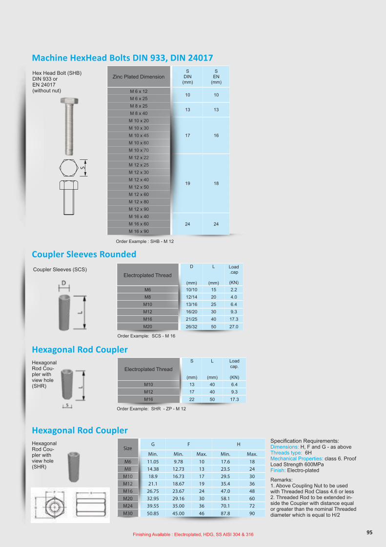
95
Electroplated Thread
D
(mm)
L
(mm)
Load.cap
(KN)M6 10/10 15 2.2M8 12/14 20 4.0M10 13/16 25 6.4M12 16/20 30 9.3M16 21/25 40 17.3M20 26/32 50 27.0
Coupler Sleeves Rounded
Coupler Sleeves (SCS)
Order Example: SCS - M 16
Electroplated Thread S
(mm)
L
(mm)
Loadcap.
(KN)M10 13 40 6.4M12 17 40 9.3M16 22 50 17.3
SizeG F H
Min. Min. Max. Min. Max.M6 11.05 9.78 10 17.6 18M8 14.38 12.73 13 23.5 24
M10 18.9 16.73 17 29.5 30M12 21.1 18.67 19 35.4 36M16 26.75 23.67 24 47.0 48M20 32.95 29.16 30 58.1 60M24 39.55 35.00 36 70.1 72M30 50.85 45.00 46 87.8 90
Hexagonal Rod Coupler
Hexagonal Rod Coupler
Hexagonal Rod Cou-pler with view hole (SHR)
Hexagonal Rod Cou-pler with view hole (SHR)
Specification Requirements:Dimensions: H, F and G - as aboveThreads type: 6HMechanical Properties: class 6. Proof Load Strength 600MPaFinish: Electro-plated
Remarks: 1. Above Coupling Nut to be used with Threaded Rod Class 4.6 or less2. Threaded Rod to be extended in-side the Coupler with distance equal or greater than the nominal Threaded diameter which is equal to H/2
Order Example: SHR - ZP - M 12
Machine HexHead Bolts DIN 933, DIN 24017
S
m
S
d
D
S
d
D
Zinc PlatedThread - ZP
Zinc Platedfor bolt - ZP
Zinc PlatedDimension- ZP
D
[mm]
D
[mm]
S/mDIN
[mm]
SDIN
[mm]
S/mISO
[mm]
SEN
[mm]
e
[mm]
d
[mm]
d
[mm]
s
[mm]
s
[mm]
Length
[mm]
Load
cap.
[kN]
Threaded Rods, Hexagon Head Bol ts, Nuts, Washers
FR AMI NG SY STEM S ACC ESSORI ES
Order Example : TR - ZP - M 12 × 1000
Order Example : HB - ZP - M 12 × 1000
Order Example: WA - ZP - M 12 - DIN 9021
Order Example: WA - ZP - M 12 - DIN 125
DIN
22
24
30
45
37
50
12
16
21
24
30
10/ 5
13/6,5
17/ 8
19/10
24/13
10
13
17
19
24
18
24
10
13
16
10/ 6
13/7,5
16/ 9,5
18/12
24/15,5
11,5
15,0
19,6
21,9
27,7
6,6
8,4
10,5
13,5
13
17
6,4
8,4
10,5
13
17
2
2
2,5
4
3
3
1,6
1,6
2
2,5
3
1000
1000
1000
1000
1000
2,2
4,0
6,4
12,9
17,3
M 6
M 8
M 10
M 12
M 16
M 6 x 12
M 6 x 25
M 8 x 25
M 8 x 40
M 10 x 20
M 10 x 30
M 10 x 45
M 10 x 60
M 10 x 70
M 12 x 22
M 12 x 25
M 12 x 30
M 12 x 40
M 12 x 50
M 12 x 60
M 12 x 80
M 12 x 90
M 16 x 40
M 16 x 60
M 16 x 90
M 8 x 25
M 10 x 30
M 10 x 45
M 12 x 25
M 12 x 30
M 12 x 40
M 12 x 60
M 12 x 80
M 16 x 40
M 16 x 60
M 16 x 90
M 6
M 8
M 10
M 12
M 16
M 6
M 8
M 10
M 12
M 16
440
9021
9021
440
9021
9021
M 6
M 8
M 10
M 12
M 12
M 16
M 6
M 8
M 10
M 12
M 16
M 8
M 10
M 12
M 16
M 6
M 8
M 10
M 12
M 16
M 6
M 8
M 10
M 12
M 16
Stainless SteelThread
Zinc PlatedThread - ZP
Stainless SteelThread
Stainless Steelfor bolt
Zinc Platedfor bolt - ZP
Stainless Steelfor bolt
Stainless SteelDimension
Material & Finishes Codes
( S. 53)
= h.d. galvanised, strength grade 4.6
= electroplated, 4.6
= , 8.8
= Stainless steel grade A4-50
strength grade
h.d. galvanised strength grade
= electroplated, strength grade 8.8
= Stainless steel grade A4-70
= Stainless steel grade A2-50
= Stainless steel grade A2-70
= Stainless steel W1.4529 HCR-50
fv
gv
fv 8.8
A4-50
gv 8.8
A4-70
A2-50
A2-70
HCR
e
S
Hex Head Bolt (SHB)DIN 933 or EN 24017(without nut)
Order Example : SHB - M 12
Zinc Plated Dimension S
DIN(mm)
SEN
(mm)
M 6 x 1210 10
M 6 x 25M 8 x 25
13 13M 8 x 40
M 10 x 20
17 16M 10 x 30M 10 x 45M 10 x 60M 10 x 70M 12 x 22
19 18
M 12 x 25M 12 x 30M 12 x 40M 12 x 50M 12 x 60M 12 x 80M 12 x 90M 16 x 40
24 24M 16 x 60M 16 x 90
Finishing Available : Electroplated, HDG, SS AISI 304 & 316
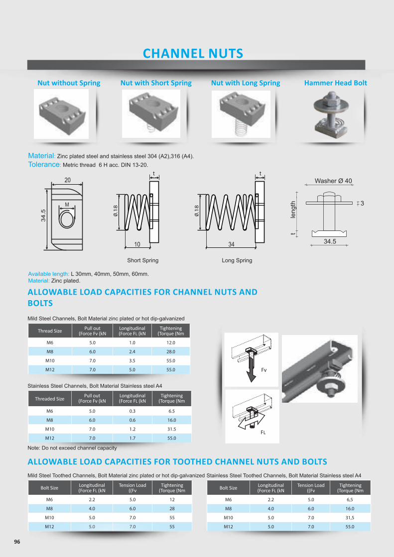
96
ALLOWABLE LOAD CAPACITIES FOR TOOTHED CHANNEL NUTS AND BOLTSMild Steel Toothed Channels, Bolt Material zinc plated or hot dip-galvanized
Bolt Size Longitudinal(Force FL (kN
Tension Load((Fv
Tightening(Torque (Nm
M6 2.2 5.0 12
M8 4.0 6.0 28
M10 5.0 7.0 55
M12 5.0 7.0 55
Nut without Spring Nut with Short Spring Nut with Long Spring Hammer Head Bolt
Material: Zinc plated steel and stainless steel 304 (A2),316 (A4).Tolerance: Metric thread 6 H acc. DIN 13-20.
t t
0.1
8
10
20
34.5
M
0.1
8
34 FL
t t
0.1
8
10
20
34.5
M
0.1
8
34 FL
t t
0.1
8
10
20
34.5
M0
.18
34 FL
Washer Ø 40
34.5
3
tle
ngth
FvFL
Stainless Steel Channels, Bolt Material Stainless steel A4
Threaded SizePull out
(Force Fv (kNLongitudinal(Force FL (kN
Tightening(Torque (Nm
M6 5.0 0.3 6.5
M8 6.0 0.6 16.0
M10 7.0 1.2 31.5
M12 7.0 1.7 55.0
Note: Do not exceed channel capacity
ALLOWABLE LOAD CAPACITIES FOR CHANNEL NUTS AND BOLTS
Mild Steel Channels, Bolt Material zinc plated or hot dip-galvanized
Thread Size Pull out(Force Fv (kN
Longitudinal(Force FL (kN
Tightening(Torque (Nm
M6 5.0 1.0 12.0
M8 6.0 2.4 28.0
M10 7.0 3.5 55.0
M12 7.0 5.0 55.0
Short Spring Long Spring
Fv
FL
CHANNEL NUTS
Available length: L 30mm, 40mm, 50mm, 60mm.Material: Zinc plated.
Stainless Steel Toothed Channels, Bolt Material Stainless steel A4
Bolt Size Longitudinal(Force FL (kN
Tension Load((Fv
Tightening(Torque (Nm
M6 2.2 5.0 6,5
M8 4.0 6.0 16.0
M10 5.0 7.0 31,5
M12 5.0 7.0 55.0
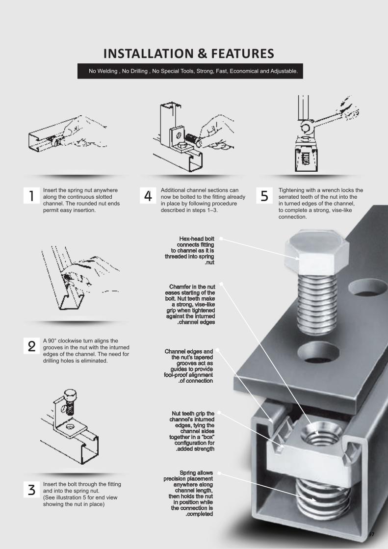
97
No Welding , No Drilling , No Special Tools, Strong, Fast, Economical and Adjustable.
Hex-head bolt connects fitting
to channel as it is threaded into spring
.nut
Chamfer in the nut eases starting of the bolt. Nut teeth make
a strong, vise-like grip when tightened against the inturned
.channel edges
Channel edges and the nut’s tapered
grooves act as guides to provide
fool-proof alignment.of connection
Nut teeth grip the channel’s inturned
edges, tying the channel sides
together in a “box” configuration for.added strength
Spring allows precision placement
anywhere along channel length,
then holds the nut in position while
the connection is.completed
INSTALLATION & FEATURES
Insert the spring nut anywhere along the continuous slotted channel. The rounded nut ends permit easy insertion.
A 90° clockwise turn aligns the grooves in the nut with the inturned edges of the channel. The need for drilling holes is eliminated.
Additional channel sections can now be bolted to the fitting already in place by following procedure described in steps 1–3.
Tightening with a wrench locks the serrated teeth of the nut into the in turned edges of the channel, to complete a strong, vise-like connection.
Insert the bolt through the fitting and into the spring nut. (See illustration 5 for end view showing the nut in place)
1
2
3
4 5
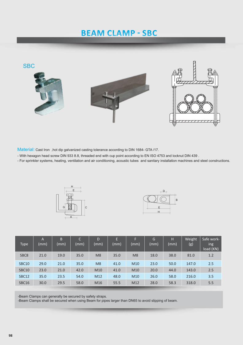
98
26
This section offers a full selection of fittings and accessories to complete SFSP’s metalframing system.
FITTINGS
STANDARD FINISHES: Hot Dip Galvanized .
FT 145
FT 150 FT 155
FITTING SPECIFICATIONS (unless noted): Hole Size—13.0mm Diameter; Hole Spacing— 20.0mm from end and48.0 mm on center; Width— 41.0mm; Thickness— 6.0mm (Order hardware separately)
FT 115FT 110 FT 120 FT 125
FT 130 FT 140
Square Plate Specify Hole Size M6,M8,M10,M12
2 Holes Plate 3 Holes Plate 4 Holes Plate
5 Holes Plate L Bracket Tee Bracket
Flat Bracket Flat Bracket
L Bracket
M6 25MM 25MM
LN 625LN 830 M8
M10 40MM40MM
LN 1040LN 1240
Part No. HoleH
Bolt Grade 8.8
LN 1650M12M16 50MM
A35
35454545
B1919
252525
C38385050
50
D3535414141
E1919212121
Beam Clamp Zinc Plated
FT 160
3 Holes Swing
E
D
CB
EH
G
H
A
FT 135
41
41
88138 184
41
138
138232 90
90
136
41
90
13890
9090
[email protected] · www.bts-saarburg.de · Tel.: +49 6581 9168-0 · Fax: +49 6581 9168-79
Material: Cast Iron ,hot dip galvanized casting tolerance according to DIN 1684- GTA /17.
- With hexagon head screw DIN 933 8.8, threaded end with cup point according to EN ISO 4753 and locknut DIN 439 .- For sprinkler systems, heating, ventilation and air conditioning, acoustic tubes and sanitary installation machines and steel constructions.
TypeA
(mm)B
(mm)C
(mm)D
(mm)E
(mm)F
(mm)G
(mm)H
(mm)Weight
(g)Safe work-
ingload (KN)
SBC8 21.0 19.0 35.0 M8 35.0 M8 18.0 38.0 81.0 1.2
SBC10 29.0 21.0 35.0 M8 41.0 M10 23.0 50.0 147.0 2.5
SBC10 23.0 21.0 42.0 M10 41.0 M10 20.0 44.0 143.0 2.5
SBC12 35.0 23.5 54.0 M12 48.0 M10 26.0 58.0 216.0 3.5
SBC16 30.0 29.5 58.0 M16 55.5 M12 28.0 58.3 318.0 5.5
-Beam Clamps can generally be secured by safety straps.-Beam Clamps shall be secured when using Beam for pipes larger than DN65 to avoid slipping of beam.
SBC
BEAM CLAMP - SBC

www.sfsp-ikk.com
ANCHORS
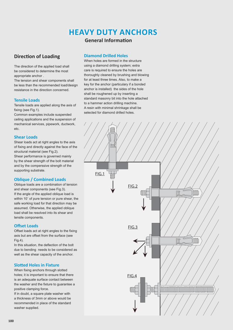
100
HEAVY DUTY ANCHORSGeneral Information
Fig.1
Fig.2
Fig.3
Fig.4FIG.4
FIG.3
FIG.2
FIG.1
Direction of Loading
The direction of the applied load shall be considered to determine the most appropriate anchor . The tension and shear components shall be less than the recommended load/design resistance in the direction concerned.
Slotted Holes in FixtureWhen fixing anchors through slotted holes; it is important to ensure that there is an adequate surface contact between the washer and the fixture to guarantee a positive clamping force.If in doubt, a square plate washer with a thickness of 3mm or above would be recommended in place of the standard washer supplied.
Tensile LoadsTensile loads are applied along the axis of fixing (see Fig.1).Common examples include suspended ceiling applications and the suspension of mechanical services, pipework, ductwork, etc.
Shear LoadsShear loads act at right angles to the axis of fixing and directly against the face of the structural material (see Fig.2).Shear performance is governed mainly by the shear strength of the bolt material and by the comperssive strength of the supporting substrate.
Oblique / Combined LoadsOblique loads are a combination of tension and shear components (see Fig.3).If the angle of the applied oblique load is within 10˚ of pure tension or pure shear, the safe working load for that direction may be assumed. Otherwise, the applied oblique load shall be resolved into its shear and tensile components.
Offset LoadsOffset loads act at right angles to the fixing axis but are offset from the surface (see Fig.4).In this situation, the deflection of the bolt due to bending needs to be considered as well as the shear capacity of the anchor.
Diamond Drilled Holes When holes are formed in the structure using a diamond drilling system; extra care is required to ensure the holes are thoroughly cleaned by brushing and blowing for at least three times. Also, to make a key for the anchor (particulary if a bonded anchor is installed) the sides of the hole shall be roughened up by inserting a standard masonry bit into the hole attached to a hammer action drilling machine.A resin with minimal shrinkage shall be selected for diamond drilled holes.
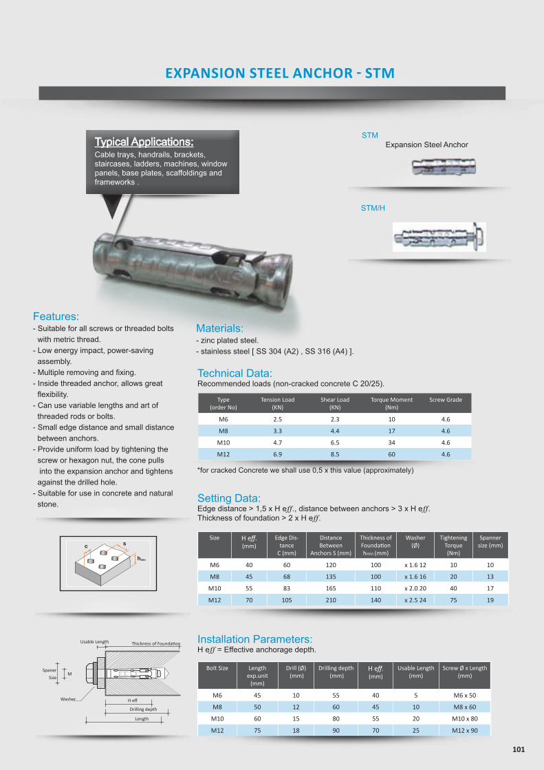
101
Technical Data:Recommended loads (non-cracked concrete C 20/25).
Setting Data:Edge distance > 1,5 x H eff., distance between anchors > 3 x H eff. Thickness of foundation > 2 x H eff.
Installation Parameters:H eff = Effective anchorage depth.
Type(order No)
Tension Load(KN)
Shear Load(KN)
Torque Moment(Nm)
Screw Grade
M6 2.5 2.3 10 4.6
M8 3.3 4.4 17 4.6
M10 4.7 6.5 34 4.6
M12 6.9 8.5 60 4.6
Size H eff.(mm)
Edge Dis-tance
C (mm)
Distance Between
Anchors S (mm)
Thickness ofFoundationhmin (mm)
Washer(Ø)
Tightening Torque (Nm)
Spannersize (mm)
M6 40 60 120 100 x 1.6 12 10 10
M8 45 68 135 100 x 1.6 16 20 13
M10 55 83 165 110 x 2.0 20 40 17
M12 70 105 210 140 x 2.5 24 75 19
Bolt Size Length exp.unit
(mm)
Drill (Ø) (mm)
Drilling depth (mm)
H eff.(mm)
Usable Length(mm)
Screw Ø x Length (mm)
M6 45 10 55 40 5 M6 x 50
M8 50 12 60 45 10 M8 x 60
M10 60 15 80 55 20 M10 x 80
M12 75 18 90 70 25 M12 x 90
*for cracked Concrete we shall use 0,5 x this value (approximately)
Features:- Suitable for all screws or threaded bolts
with metric thread.- Low energy impact, power-saving
assembly.- Multiple removing and fixing.- Inside threaded anchor, allows great
flexibility.- Can use variable lengths and art of
threaded rods or bolts.- Small edge distance and small distance
between anchors.- Provide uniform load by tightening the
screw or hexagon nut, the cone pulls into the expansion anchor and tightens
against the drilled hole. - Suitable for use in concrete and natural
stone.
H eff
Thickness of Foundation
Length
Washer
MSpaner
Size
Drilling depth
Usable Length
AHM Sleeve Anchor serutaeF
secnatsidecapsdnaegdellamS•• Torque controlled expansion• Zinc plated > 5µm• Through xing
Applications snoitcurtsnoc-rednu,selorp,senihcam,snoitcurtsnocleets
noitallatsnI
S-AHM Sleeve Anchor with hexagon screw htgneLmmØllirDmm
htpedgnillirDdaerhTmm
htgnelelbasUmm
htpedgnitteSmin.mm
6M6M8M8M01M01M
B-AHM Sleeve Anchor with threaded bolt and nut
58 Mungo Befestigungstechnik AG
Met
al P
rodu
cts
kat_en-2007-11-29.indd 58 4.12.2007 10:13:36 Uhr
Tension load (kN)
Type(Order No)
Shear load (kN)
Bending moment (Nm)
Distance betweenanchor S (mm)
6M8M01M21M
2.03.05.0
5.7
105120150225
Min. thickness of found
(hmin) mm
Tighten torque(Nm)
Spannersize (SAS)
Spannersize (SAB)
Drill Ø(mm)
Size(mm)
Length(mm)
Usablelength(mm)
Drilling depth(mm)
Settingdepth min.
(mm)88
10101212
M6M6M8M8
M10M10
4560608070
100
555560607070
51515251535
353540405050
Drill Ø(mm)
Size(mm)
Length(mm)
Usablelength(mm)
Drilling depth(mm)
Settingdepth min.
(mm)88
101010121212161616
M6M6M8M8M8
M10M10M10M12M12M12
406550759575
10013065
110145
5555606060707070909090
5255
30501540705
2560
3535404040505050757575
Plug & drill Ø(mm)
Length(mm)
UsableDrilling Depth(mm)
Length(mm)
SettingDepth Min.
(mm)5406060807001
555506060707
55151525153
535304040505
8801012121
2.53.35.58.0
90.0100.0120.0140.0
10.013.017.0---
10.013.015.019.0
8.025.040.050.0
4.205.30
12.8025.0
Distance to edge C (mm)
55.060.075.0
115.0
Tinst
Materials:- zinc plated steel.- stainless steel [ SS 304 (A2) , SS 316 (A4) ].
EXPANSION STEEL ANCHOR - STM
Typical Applications:Cable trays, handrails, brackets, staircases, ladders, machines, window panels, base plates, scaffoldings and frameworks .
FR AMI NG SY STEM S ACC ESSORI ES
s
L
D
L
Loadcap.
[kN]
Order example:
Order example:
Loadcap.
[kN]
S
[mm]
L
[mm]
D
[mm]
L
[mm]
10/10
12/14
13/16
16/20
21/25
26/32
13
17
22
15
20
25
30
40
50
40
40
50
2,2
4,0
6,4
9,3
17,3
27,0
6,4
9,3
17,3
M 6
M 8
M 10
M 12
M 16
M 20
M 10
M 12
M 16
M 6
M 8
M 10
M 12
M 16
M 20
M 10
M 12
M 16
CS - GV - M 16
HRC - GV - M 12
Coupler Sleeves, Square washers ,Sleeve Anchor ,Throught Anchor .......
Throught Anchor
Sleeve Anchor
b
da
b
d
a
Order Example: SW 41/41 - HDG - M 12
40 x 40 x 5
40 x 40 x 5
40 x 40 x 5
40 x 40 x 6
40 x 40 x 6
40 x 40 x 6
a x b x d
[mm]
M 10
M 12
M 16
M 6
M 10
M 12
M 6
M 10
M 12
M 10
M 12
M 16
ElectroplatedThread - GV
ElectroplatedThread - GV
Stainless SteelThread
Stainless SteelThread
H.D. Galvanisedfor Bolts - HDG
Stainless Steelfor Bolts
Yellow zinc plated SteelThread (Zn)
L (mm)
Order example:
M 6
M 8
M 10
M 12
45
50
60
74
M 6
M 8
M 10
STM - Zn - M 12
Stainless Steel
Thread
Drill
(mm)
10
12
15
18
Min.Drill hole
(mm)
55
60
75
90
M 6
M 8
M 10
Stainless Steel
Thread
Yellow zinc plated SteelThread (Zn)
Screwx Length (mm)
Order example:
M 6
M 8
M 10
M 12
6x50
8x60
10x80
12x90
STMH - Zn - M 12
S max fixing(mm)
5
10
20
25
Yellow zinc plated Steel Thread (Zn)
10
25
45
75
10.3
12.2
17.1
25.3
9.6
17.5
27.8
40.5
M 6
M 8
M 10
M 12
TypeMax Torque
(mm)Pull Out
Shear
8
19
38
9.5
14
19
8.4
15.4
24.4
Max Torque(mm)
Pull Out
Shear
Stainless SteelThread
Pull-out values in KN -concrete R 250kg/cm2
its is advisable to apply safty factor in consideration of the various ways of employment
(1KN=100kg)
STM/H
FR AMI NG SY STEM S ACC ESSORI ES
s
L
D
L
Loadcap.
[kN]
Order example:
Order example:
Loadcap.
[kN]
S
[mm]
L
[mm]
D
[mm]
L
[mm]
10/10
12/14
13/16
16/20
21/25
26/32
13
17
22
15
20
25
30
40
50
40
40
50
2,2
4,0
6,4
9,3
17,3
27,0
6,4
9,3
17,3
M 6
M 8
M 10
M 12
M 16
M 20
M 10
M 12
M 16
M 6
M 8
M 10
M 12
M 16
M 20
M 10
M 12
M 16
CS - GV - M 16
HRC - GV - M 12
Coupler Sleeves, Square washers ,Sleeve Anchor ,Throught Anchor .......
Throught Anchor
Sleeve Anchor
b
da
b
d
a
Order Example: SW 41/41 - HDG - M 12
40 x 40 x 5
40 x 40 x 5
40 x 40 x 5
40 x 40 x 6
40 x 40 x 6
40 x 40 x 6
a x b x d
[mm]
M 10
M 12
M 16
M 6
M 10
M 12
M 6
M 10
M 12
M 10
M 12
M 16
ElectroplatedThread - GV
ElectroplatedThread - GV
Stainless SteelThread
Stainless SteelThread
H.D. Galvanisedfor Bolts - HDG
Stainless Steelfor Bolts
Yellow zinc plated SteelThread (Zn)
L (mm)
Order example:
M 6
M 8
M 10
M 12
45
50
60
74
M 6
M 8
M 10
STM - Zn - M 12
Stainless Steel
Thread
Drill
(mm)
10
12
15
18
Min.Drill hole
(mm)
55
60
75
90
M 6
M 8
M 10
Stainless Steel
Thread
Yellow zinc plated SteelThread (Zn)
Screwx Length (mm)
Order example:
M 6
M 8
M 10
M 12
6x50
8x60
10x80
12x90
STMH - Zn - M 12
S max fixing(mm)
5
10
20
25
Yellow zinc plated Steel Thread (Zn)
10
25
45
75
10.3
12.2
17.1
25.3
9.6
17.5
27.8
40.5
M 6
M 8
M 10
M 12
TypeMax Torque
(mm)Pull Out
Shear
8
19
38
9.5
14
19
8.4
15.4
24.4
Max Torque(mm)
Pull Out
Shear
Stainless SteelThread
Pull-out values in KN -concrete R 250kg/cm2
its is advisable to apply safty factor in consideration of the various ways of employment
(1KN=100kg)
STM Expansion Steel Anchor
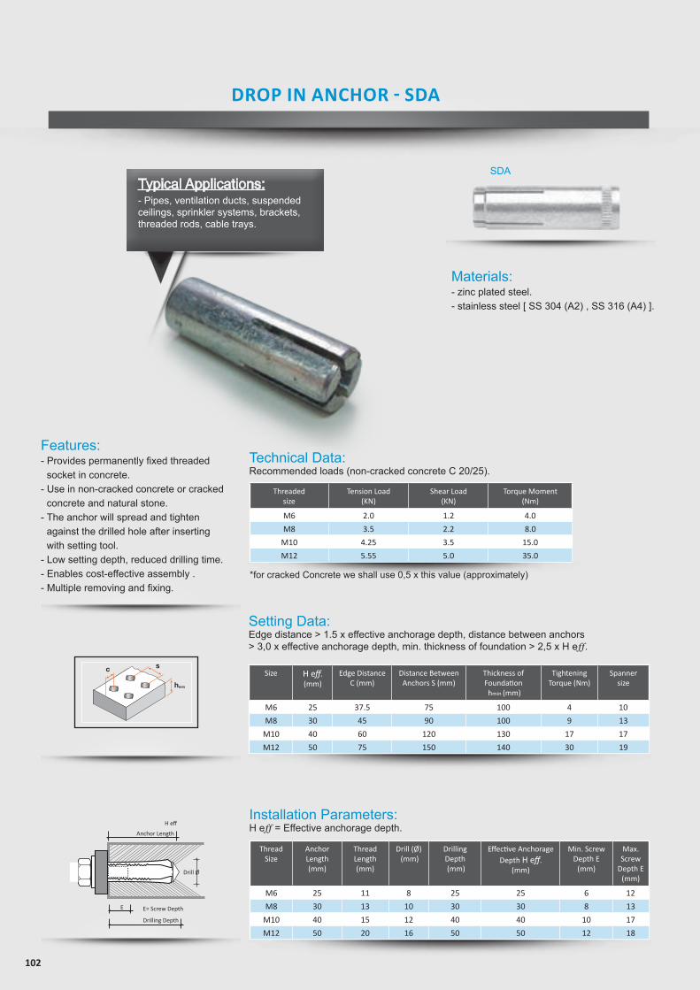
102
Technical Data:Recommended loads (non-cracked concrete C 20/25).
Setting Data:Edge distance > 1.5 x effective anchorage depth, distance between anchors > 3,0 x effective anchorage depth, min. thickness of foundation > 2,5 x H eff.
Installation Parameters:H eff = Effective anchorage depth.
Threadedsize
Tension Load(KN)
Shear Load(KN)
Torque Moment(Nm)
M6 2.0 1.2 4.0
M8 3.5 2.2 8.0
M10 4.25 3.5 15.0
M12 5.55 5.0 35.0
Size H eff.(mm)
Edge DistanceC (mm)
Distance BetweenAnchors S (mm)
Thickness ofFoundation hmin (mm)
Tightening Torque (Nm)
Spannersize
M6 25 37.5 75 100 4 10
M8 30 45 90 100 9 13
M10 40 60 120 130 17 17
M12 50 75 150 140 30 19
Thread Size
AnchorLength (mm)
ThreadLength (mm)
Drill (Ø) (mm)
Drilling Depth (mm)
Effective Anchorage Depth H eff.
(mm)
Min. Screw Depth E
(mm)
Max.Screw
Depth E (mm)
M6 25 11 8 25 25 6 12
M8 30 13 10 30 30 8 13
M10 40 15 12 40 40 10 17
M12 50 20 16 50 50 12 18
*for cracked Concrete we shall use 0,5 x this value (approximately)
Features:- Provides permanently fixed threaded
socket in concrete.- Use in non-cracked concrete or cracked
concrete and natural stone.- The anchor will spread and tighten
against the drilled hole after inserting with setting tool.
- Low setting depth, reduced drilling time.- Enables cost-effective assembly .- Multiple removing and fixing.
Anchor Length
Drilling Depth
E E= Screw Depth
Drill Ø
H eff
AHM Sleeve Anchor serutaeF
secnatsidecapsdnaegdellamS•• Torque controlled expansion• Zinc plated > 5µm• Through xing
Applications snoitcurtsnoc-rednu,selorp,senihcam,snoitcurtsnocleets
noitallatsnI
S-AHM Sleeve Anchor with hexagon screw htgneLmmØllirDmm
htpedgnillirDdaerhTmm
htgnelelbasUmm
htpedgnitteSmin.mm
6M6M8M8M01M01M
B-AHM Sleeve Anchor with threaded bolt and nut
58 Mungo Befestigungstechnik AG
Met
al P
rodu
cts
kat_en-2007-11-29.indd 58 4.12.2007 10:13:36 Uhr
Tension load (kN)
Type(Order No)
Shear load (kN)
Bending moment (Nm)
Distance betweenanchor S (mm)
6M8M01M21M
2.03.05.0
5.7
105120150225
Min. thickness of found
(hmin) mm
Tighten torque(Nm)
Spannersize (SAS)
Spannersize (SAB)
Drill Ø(mm)
Size(mm)
Length(mm)
Usablelength(mm)
Drilling depth(mm)
Settingdepth min.
(mm)88
10101212
M6M6M8M8
M10M10
4560608070
100
555560607070
51515251535
353540405050
Drill Ø(mm)
Size(mm)
Length(mm)
Usablelength(mm)
Drilling depth(mm)
Settingdepth min.
(mm)88
101010121212161616
M6M6M8M8M8
M10M10M10M12M12M12
406550759575
10013065
110145
5555606060707070909090
5255
30501540705
2560
3535404040505050757575
Plug & drill Ø(mm)
Length(mm)
UsableDrilling Depth(mm)
Length(mm)
SettingDepth Min.
(mm)5406060807001
555506060707
55151525153
535304040505
8801012121
2.53.35.58.0
90.0100.0120.0140.0
10.013.017.0---
10.013.015.019.0
8.025.040.050.0
4.205.30
12.8025.0
Distance to edge C (mm)
55.060.075.0
115.0
Tinst
Materials:- zinc plated steel.- stainless steel [ SS 304 (A2) , SS 316 (A4) ].
SDA
DROP IN ANCHOR - SDA
Typical Applications:- Pipes, ventilation ducts, suspended ceilings, sprinkler systems, brackets, threaded rods, cable trays.
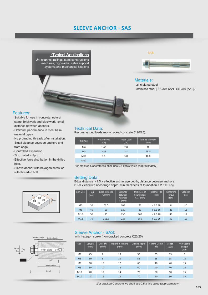
103
Technical Data:Recommended loads (non-cracked concrete C 20/25).
Bolt SizeTension Load
(KN)Shear Load
(KN)Torque Moment
(Nm)
M6 1.40 2.0 10
M8 2.45 3.3 25.0
M10 3.5 5.0 40.0
M12 .... .... ....
Bolt Size H eff.(mm)
Edge DistanceC (mm)
Distance BetweenAnchors S (mm)
Thickness ofFoundationhmin (mm)
Washer (Ø)(mm)
Tightening Torque (Nm)
Spannersize
M6 35 52.5 105 70 x 1.6 18 8 10
M8 40 60 120 80 x 1.6 16 25 13
M10 50 75 150 100 x 2.0 20 40 17
M12 75 112.5 225 150 x 2.0 26 50 19
Sleeve Anchor - SAS:with hexagon screw (non-cracked concrete C20/25).
Size Length (mm)
Drill (Ø) (mm)
Hole Ø in Fixture (mm)
Drilling Depth (mm)
Setting Depth(Ø)
H eff.(mm)
Min.Usable Length(mm)
M6 45 8 10 55 35 35 5
M6 60 8 10 55 35 35 15
M8 60 10 12 60 40 40 15
M8 80 10 12 60 40 40 25
M10 70 12 14 70 50 50 15
M10 100 12 14 70 60 50 35
Setting Data:Edge distance > 1.5 x effective anchorage depth, distance between anchors> 3,0 x effective anchorage depth, min. thickness of foundation > 2,5 x H eff.
*for cracked Concrete we shall use 0,5 x this value (approximately)
.(for cracked Concrete we shall use 0,5 x this value (approximately*
Materials:- zinc plated steel.- stainless steel [ SS 304 (A2) , SS 316 (A4) ].
AHM Sleeve Anchor serutaeF
secnatsidecapsdnaegdellamS•• Torque controlled expansion• Zinc plated > 5µm• Through xing
Applications snoitcurtsnoc-rednu,selorp,senihcam,snoitcurtsnocleets
noitallatsnI
S-AHM Sleeve Anchor with hexagon screw htgneLmmØllirDmm
htpedgnillirDdaerhTmm
htgnelelbasUmm
htpedgnitteSmin.mm
6M6M8M8M01M01M
B-AHM Sleeve Anchor with threaded bolt and nut
58 Mungo Befestigungstechnik AG
Met
al P
rodu
cts
kat_en-2007-11-29.indd 58 4.12.2007 10:13:36 Uhr
Tension load (kN)
Type(Order No)
Shear load (kN)
Bending moment (Nm)
Distance betweenanchor S (mm)
6M8M01M21M
2.03.05.0
5.7
105120150225
Min. thickness of found
(hmin) mm
Tighten torque(Nm)
Spannersize (SAS)
Spannersize (SAB)
Drill Ø(mm)
Size(mm)
Length(mm)
Usablelength(mm)
Drilling depth(mm)
Settingdepth min.
(mm)88
10101212
M6M6M8M8
M10M10
4560608070
100
555560607070
51515251535
353540405050
Drill Ø(mm)
Size(mm)
Length(mm)
Usablelength(mm)
Drilling depth(mm)
Settingdepth min.
(mm)88
101010121212161616
M6M6M8M8M8
M10M10M10M12M12M12
406550759575
10013065
110145
5555606060707070909090
5255
30501540705
2560
3535404040505050757575
Plug & drill Ø(mm)
Length(mm)
UsableDrilling Depth(mm)
Length(mm)
SettingDepth Min.
(mm)5406060807001
555506060707
55151525153
535304040505
8801012121
2.53.35.58.0
90.0100.0120.0140.0
10.013.017.0---
10.013.015.019.0
8.025.040.050.0
4.205.30
12.8025.0
Distance to edge C (mm)
55.060.075.0
115.0
Tinst
Setting Depth
H eff
Length
Washer
MSpaner
Size
Drilling DepthUsable Length
Drill Ø
SAS
SLEEVE ANCHOR - SAS
:Typical Applications Uni-channel ,railings, steel constructions
, machines, high-racks, cable support .systems and mechanical fixations
Features:- Suitable for use in concrete, natural
stone, brickwork and blockwork- small distance between anchors.
- Optimum performance in most base material types.
- No protruding threads after installation.- Small distance between anchors and
from edge.- Controlled expansion.- Zinc plated > 5µm.- Effective force distribution in the drilled
hole.- Sleeve anchor with hexagon screw or
with threaded bolt.
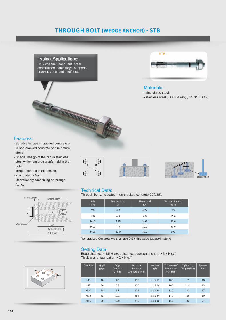
104
Typical Applications:Uni - channel, hand rails, steel construction, cable trays, supports, bracket, ducts and shelf feet.
Technical Data:Through bolt zinc plated (non-cracked concrete C20/25).
Setting Data:Edge distance > 1,5 H eff. , distance between anchors > 3 x H eff.Thickness of foundation > 2 x H eff.
BoltSize
Tension Load(KN)
Shear Load(KN)
Torque Moment(Nm)
M6 2.0 1.90 4.0
M8 4.0 4.0 15.0
M10 5.95 5.95 30.0
M12 7.5 10.0 50.0
M16 12.0 16.0 100
Bolt Size H eff.(mm)
Edge DistanceC (mm)
Distance Between
Anchors S (mm)
Washer(Ø)
Thickness ofFoundationhmin (mm)
Tightening Torque (Nm)
SpannerSize
M6 40 60 120 x 1.6 12 100 7 10
M8 50 75 150 x 1.6 16 100 14 13
M10 58 87 174 x 2.0 20 120 30 17
M12 68 102 204 x 2.5 24 140 35 19
M16 80 120 240 x 3.0 30 160 80 24
*for cracked Concrete we shall use 0,5 x this value (approximately)
Materials:- zinc plated steel. - stainless steel [ SS 304 (A2) , SS 316 (A4) ].
Features: - Suitable for use in cracked concrete or
in non-cracked concrete and in natural stone.
- Special design of the clip in stainless steel which ensures a safe hold in the hole.
- Torque controlled expansion.- Zinc plated > 5µm.- User friendly, face fixing or through
fixing.
Throughbolt, stainless steel A4/316
serutaeFetercnocdekcarcnurof7noitpOlavorppAlacinhceTnaeporuE•
• Torque controlled expansion• Applications in damp areas and outdoors• Stainless steel A4/316• Face xing or through xing
Applications ,senihcam,snoitcurtsnocleets,sgniliar,syartelbac,sedacaf
under-constructions, high-racks, pro les
Tension load (kN)
Shear load (kN)
Bending moment (Nm)
Edge Distance C (mm)
He�. (mm)
Distance betweenanchor S (mm)
Thickness offoundation
(mm)
Tighten torque(Nm)
Spanner size
6M 2.64.15.89.214
3.36.38.51223
5153050
100
5.513
26.546.5
118.5
4050586880
Washer (Ø)
12 x 1.616 x 1.620 x 2.024 x 2.530 x 3.0
02106 001 018M 05157 001 3101M 47178 021 7121M 402201 041 9161M 042021 061 42
noitallatsnI
2
03505604015660452086040459672505803010680501088055158805525980554511833506015301070185515901850301101855452101850604101850806101850010810194508218651011218603521218605541218607561218609581210701511610851031610803541610854061610856081610010306102
50 Mungo Befestigungstechnik AG
Plug & drill Ø(mm)
Length(mm)
UsableLength(mm)
Settingdepth min.
(mm)
kat_en-2007-11-29.indd 50 4.12.2007 10:12:24 Uhr
Bolt Size
Tinst
Through bolt
Setting Depth
H eff
Bolt Length
Washer
Drilling DepthUsable Length
Drill ØAHM Sleeve Anchor
serutaeFsecnatsidecapsdnaegdellamS•
• Torque controlled expansion• Zinc plated > 5µm• Through xing
Applications snoitcurtsnoc-rednu,selorp,senihcam,snoitcurtsnocleets
noitallatsnI
S-AHM Sleeve Anchor with hexagon screw htgneLmmØllirDmm
htpedgnillirDdaerhTmm
htgnelelbasUmm
htpedgnitteSmin.mm
6M6M8M8M01M01M
B-AHM Sleeve Anchor with threaded bolt and nut
58 Mungo Befestigungstechnik AG
Met
al P
rodu
cts
kat_en-2007-11-29.indd 58 4.12.2007 10:13:36 Uhr
Tension load (kN)
Type(Order No)
Shear load (kN)
Bending moment (Nm)
Distance betweenanchor S (mm)
6M8M01M21M
2.03.05.0
5.7
105120150225
Min. thickness of found
(hmin) mm
Tighten torque(Nm)
Spannersize (SAS)
Spannersize (SAB)
Drill Ø(mm)
Size(mm)
Length(mm)
Usablelength(mm)
Drilling depth(mm)
Settingdepth min.
(mm)88
10101212
M6M6M8M8
M10M10
4560608070
100
555560607070
51515251535
353540405050
Drill Ø(mm)
Size(mm)
Length(mm)
Usablelength(mm)
Drilling depth(mm)
Settingdepth min.
(mm)88
101010121212161616
M6M6M8M8M8
M10M10M10M12M12M12
406550759575
10013065
110145
5555606060707070909090
5255
30501540705
2560
3535404040505050757575
Plug & drill Ø(mm)
Length(mm)
UsableDrilling Depth(mm)
Length(mm)
SettingDepth Min.
(mm)5406060807001
555506060707
55151525153
535304040505
8801012121
2.53.35.58.0
90.0100.0120.0140.0
10.013.017.0---
10.013.015.019.0
8.025.040.050.0
4.205.30
12.8025.0
Distance to edge C (mm)
55.060.075.0
115.0
Tinst
STB
THROUGH BOLT (WEDGE ANCHOR) - STB
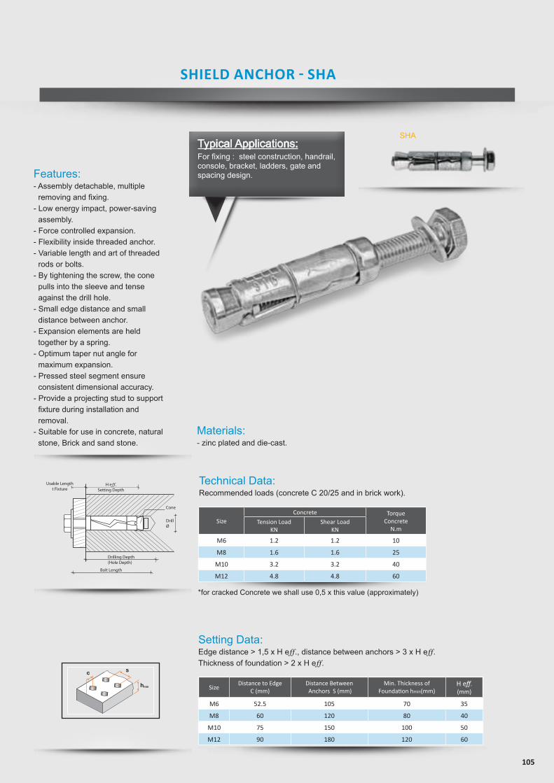
105
Features:- Assembly detachable, multiple
removing and fixing.- Low energy impact, power-saving
assembly.- Force controlled expansion.- Flexibility inside threaded anchor.- Variable length and art of threaded
rods or bolts.- By tightening the screw, the cone
pulls into the sleeve and tense against the drill hole.
- Small edge distance and small distance between anchor.
- Expansion elements are held together by a spring.
- Optimum taper nut angle for maximum expansion.
- Pressed steel segment ensure consistent dimensional accuracy.
- Provide a projecting stud to support fixture during installation and removal.
- Suitable for use in concrete, natural stone, Brick and sand stone.
Technical Data:Recommended loads (concrete C 20/25 and in brick work).
Setting Data:Edge distance > 1,5 x H eff., distance between anchors > 3 x H eff. Thickness of foundation > 2 x H eff.
SizeConcrete Torque
ConcreteN.m
Tension Load KN
Shear LoadKN
M6 1.2 1.2 10
M8 1.6 1.6 25
M10 3.2 3.2 40
M12 4.8 4.8 60
SizeDistance to Edge
C (mm)Distance Between Anchors S (mm)
Min. Thickness ofFoundation hmin(mm)
H eff.(mm)
M6 52.5 105 70 35
M8 60 120 80 40
M10 75 150 100 50
M12 90 180 120 60
*for cracked Concrete we shall use 0,5 x this value (approximately)
Materials:- zinc plated and die-cast.
SHA
H eff.Setting Depth
Usable Lengtht Fixture
DrillØ
Drilling Depth(Hole Depth)
Bolt Length
Cone
AHM Sleeve Anchor serutaeF
secnatsidecapsdnaegdellamS•• Torque controlled expansion• Zinc plated > 5µm• Through xing
Applications snoitcurtsnoc-rednu,selorp,senihcam,snoitcurtsnocleets
noitallatsnI
S-AHM Sleeve Anchor with hexagon screw htgneLmmØllirDmm
htpedgnillirDdaerhTmm
htgnelelbasUmm
htpedgnitteSmin.mm
6M6M8M8M01M01M
B-AHM Sleeve Anchor with threaded bolt and nut
58 Mungo Befestigungstechnik AG
Met
al P
rodu
cts
kat_en-2007-11-29.indd 58 4.12.2007 10:13:36 Uhr
Tension load (kN)
Type(Order No)
Shear load (kN)
Bending moment (Nm)
Distance betweenanchor S (mm)
6M8M01M21M
2.03.05.0
5.7
105120150225
Min. thickness of found
(hmin) mm
Tighten torque(Nm)
Spannersize (SAS)
Spannersize (SAB)
Drill Ø(mm)
Size(mm)
Length(mm)
Usablelength(mm)
Drilling depth(mm)
Settingdepth min.
(mm)88
10101212
M6M6M8M8
M10M10
4560608070
100
555560607070
51515251535
353540405050
Drill Ø(mm)
Size(mm)
Length(mm)
Usablelength(mm)
Drilling depth(mm)
Settingdepth min.
(mm)88
101010121212161616
M6M6M8M8M8
M10M10M10M12M12M12
406550759575
10013065
110145
5555606060707070909090
5255
30501540705
2560
3535404040505050757575
Plug & drill Ø(mm)
Length(mm)
UsableDrilling Depth(mm)
Length(mm)
SettingDepth Min.
(mm)5406060807001
555506060707
55151525153
535304040505
8801012121
2.53.35.58.0
90.0100.0120.0140.0
10.013.017.0---
10.013.015.019.0
8.025.040.050.0
4.205.30
12.8025.0
Distance to edge C (mm)
55.060.075.0
115.0
Tinst
SHIELD ANCHOR - SHA
Typical Applications:For fixing : steel construction, handrail, console, bracket, ladders, gate and spacing design.
106
OUTLETS
FACTORIES
SFSP - [email protected]
SFSP / Kingdom of Saudi ArabiaSpecialized Factory for Steel Products - 3rd Industrial City / JeddahTel: +966 12 637 4482Fax: +966 12 636 1963
Specialized Factory
www.sfsp-ikk.comfor Steel Products Co. Ltd
Sale Distributors
Kigdom Of Saudi Arabia [email protected]
Jeddah Tel : +966 12 627 8222Fax: +966 12 627 8722
Jeddah - Ghurab Showroom Tel : +966 12 667 2000Fax: +966 12 661 4306
Mak kah, TaifTel : +966 12 541 1206Fax: +966 12 532 1675
Riyadh NorthTel : +966 11 415 5465Fax: +966 11 456 6627
Riyadh SouthTel : +966 11 448 0112Fax: +966 11 447 7421
Riyadh - WestTel : +966 11 431 6271Fax: +966 11 431 7642
Qassim / BuraidahTel : +966 16 382 3946Fax: +966 16 385 2186
Qassim ShowroomTel : +966 16 385 2598Fax: +966 16 385 4262
Hafr el BatinTel : +966 13 729 3644Fax: +966 13 729 3644
HailTel : +966 16 543 3931Fax: +966 16 543 3935
Skakah / QurayyatTel : +966 14 626 3904Fax: +966 14 626 3905
TabukTel : +966 14 423 5203Fax: +966 14 423 5203
Khamis MushaytTel : +966 17 237 5929Fax: +966 17 237 8783
NajranTel : +966 17 546 3873Fax : +966 17 546 3873
SharorahTel : +966 17 532 8153Fax: +966 17 532 8153
Al -BahaTel : +966 17 237 5929Fax: +966 17 237 8783
GizanTel : +966 17 321 6660Fax: +966 17 321 0665
Al QunfudahTel : +966 17 7350 266Fax: +966 17 7350 266
Mad inahTel : +966 14 842 1095Fax: +966 14 842 1090
Mad inah Showroom - UPF Tel : +966 14 834 6244Fax: +966 14 834 5082 YanbuTel : +966 14 390 1499Fax: +966 14 322 7101
DammamTel : +966 13 859 0097Fax: +966 13 857 8177
Dammam / Showroom Tel : +966 13 834 9300Fax: +966 13 834 9457
JubailTel : +966 13 361 4390Fax: +966 13 362 4499
Hufuf Tel : +966 13 530 1474Fax: +966 13 530 7144
Hufuf / ShowroomTel : +966 13 586 9732Fax: +966 13 530 7144
107
FACTORIES
Sale Distributors
SFSP / [email protected]
SIGMA Factory for Steel Products - DIC (Dubai Industrial City)Tel : +971 4 818 1919
SFSP / [email protected]
Specialized Factory for Steel Products Lot No. 235 A- 3rd industrial zone 2nd service road 6th of October City Giza Tel : +20 2 3820 6477Fax: +20 2 3820 6036
SFSP / [email protected]
Specialized Factory for Steel Products / s.a.r.l Tanayel, BekaaTel: +961 8 514 290Fax: +961 8 514 291
Bahrain [email protected]
Manama / Bahrain Tel : +973 17 874 897Fax: +973 17 789 470
Kuwait City / Kuwait Tel : +965 2 4924 937Fax: +965 2 4924 938
United Arab EmiratesDubai -Al Rashidiyah / [email protected] : +971 4 2591 773Fax : +971 4 2591 774
Dubai - DIC / UAE Tel : +971 4 8181 900
Abu Dhabi - Musaffah / [email protected]: +971 2 552 3393Fax: +971 2 552 5499
Beirut / LebanonTel : +961 1 858 277Fax: +961 1 858 276
Muscat / OmanTel : +968 24 591 006Fax : +968 24 597 006
Amman / JordanTel : +962 6 556 3030Fax: +962 6 554 7911
AqabaTel : +962 6 556 3030Fax: +962 6 554 7911
Cairo 6th of October City / EgyptTel : +20 2 3820 6477Fax: +20 2 3820 6036
ENGINEERING, DESIGN, MARKETING & MULTIMEDIA
Unitech Deutschland [email protected] Tel : +49 711 6868 7222 Fax: +49 711 6868 7223
Multi-D s.a.r.lLebanon [email protected] Beirut Tel : +961 1 841 155Fax: +961 1 841 156

www.sfsp-ikk.com
SFSP makes every effort to maintain the accuracy and quality of the information provided in this Catalogue.
However, SFSP cannot guarantee and assumes legal liability or responsibility for the accuracy or completeness of the information provided.
Whilst every care has been exercised in the preparation of this catalogue to ensure that any advice, recommendations or information is accurate, no liability or responsibility of any kind is accepted.
Project working details should be entrusted to appropriately qualified and experienced persons, case by case.
With a policy of continuous product development, SFSP may modify product design and specification without due notice.
In case of any questions or remarks, feel free to contact the R&D Department.
DISTRIBUTED BY: