c. advanced operationsc. advanced operations - …. advanced operationsc. advanced operations ......
TRANSCRIPT

C. Advanced Operations C. Advanced OperationsC2. Using CAD-modeling function perfectly
< ICON GUIDE>Some of function in Mold EX-Press limits CAD software.Please refer to the ICONs shown in the bottom each page.
ACAC AutoCad
CACA CATIA SWSW SolidWorks
NXNX NX P/EP/E Pro/ENGINEER
CRCR PTC Creo
57

Mold EX-Press automatically shows the selectable ranges of the parameters with specifiable unit by default.
If the basic sizes are adjusted, the selectable range of the correlated parameters are adjusted correspondingly.
Once correct numerical values are all determined, Misumi’s standard part number is generated automatically without an error.
This also applies to the alteration work.
C2-1. How to configure the part number
In the product parameter aspect, all parameters are constrained by the relevant formulae. After the basic size is determined, the relevant selectable ranges or respective parameters are shown.You don’t have to recalculate to determine the parameters, so that the design time is saved.
11
33
44
5522
Go to the Product Configuration (third page), and then designate the size .
58

Firstly, open the Home,and then select the parts.
Complete the parameters(third page).
C2-2. Checking the part shape by previewing in 3D (before locating in CAD)
After the parts are selected, to ensure whether the specifications of selected parts and the additional processing are correct, the shapes of the parts can be checked through the preview function of the 3D models so that the time is saved.
11 33
4422
Click the 3D view tab to seethe selected parts modeledin 3D.
Switch to [Alteration] screenif additional work is required.The part shape in preview window will correspond to your alteration selection immediately.
59

After selecting specification in [Detailed parameter setting], go to click [CAD].In this page, we will set Stepped Ejector Pins to Plate.
Select a product category (ex; Stepped Ejector Pins).
Select the plate to be subtracted and locate the part on it.
Hole processing data is automatically available when you will output parts from Mold EX-Press for assembly. The size of processing hole is based on standards of 【Product data】standard hole processing *Only available for NX Assembly model and Pro/E or Creo.
C2-3. Using subtract solid function at the same time of locating a model
11
33
44
22
[Key point]
Check the function for easy layout you need.
Please untick if automatic subtraction is unnecessary. Even unticked, subtract information is stored so that it can be recalledlater.
[Key point]
For detailed setting, please refer to 「C2-5」
Please select your required hole processing parts. Several hole processing is available.
55
NXNX P/EP/E CRCR 60

[Key point]For details, please refer to C2-5. Autoconfiguration setting.
Tick [Use "Automatic screw layout"]
C2-4. Locating the related components at the same time without a pause
11
22
Suggestion for sequential positioning of related parts follows after locating the part.Select the related parts indicated in the window, then click [Next]. (e.g: related part, sprue bushing guide, SBGN)
33
[Key point]The located parts, mounting bolts in this case, are not set item which will be added to BOM list as individual items.For details, please refer to C2-5. Autoconfiguration setting.
Once the main part is located in CAD, Mold EX-Press simultane-ously and sequentially suggests to layout the mounting bolts and related components so that efficiency in designing drastically improves.*Only available for NX Assembly model and Pro/E or Creo.
After selecting specification in 「Detailed parameter setting」of sprue bushing guide SBGN,go to click [CAD] .
44
Parts design is completed efficiently by using convenient functions of simultaneous locating and sequential locating.
55
SXGM: Primarily selected original part
SBGN: Selected by sequential positioning of the related parts
CB: Selected by automatic screw layout CB
SXGM
SBGN
After selecting specification in 「Detailed parameter setting」, go to click [CAD].
NXNX P/EP/E CRCR61

C2-5. Autoconfiguration setting for model-related functions
11 Autoconfiguration can be set at your preferable usability.
22
[Key point]Always OFF: This function does not work at allRemind each time: Pop up window always opens to alert when configurationAlways ON: This function always works without an alert
Mold EX-Press' useful functions such as subtract solid, automatic screw layout, and sequential positioning can be set automatically ON or OFF to suit your habits in designing. This is only available for NX assembly structure and Pro/E.
Go to [MODEL OUTPUT CAD setting] in [Help] page.
NXNX P/EP/E CRCR 62

CAD interface comes out for your operation.
C2-6. Jumping swiftly from Mold EX-Press to CAD interface
Without closing Mold EX-Press, you can go bsck to CAD by cliking smoller size.
11
22
33Click “Smaller Size”in Product Configuration page.
Click menu「Standard Components for Plastic Mold」in「MEX(mold)」,You can go back Mold EX-Press.
ACAC CACA CRCRNXNX P/EP/ESWSW63

Select [Modify] from the menu of Mold EX-Press in the tool bar.
Display changeable parts and click [Edit]in Mold Ex-Press tool bar.
Return to Product Configuration page of Mold EX-Press which displays the parameters currently selected. Re-edit the parameters and click [Next].
The model is updated.
C2-7. Modifying dimensions of the model being located on CAD
You don't have to start parts selection from the first step if you want to modify dimensions of the model which is once located on CAD. *This function is not available in Auto CAD circumstance.
11 33
4422
[Key Point]
Only in Pro/E, you need to click[Regenerate the model].
[Key Point]
Under Solid works circumstance,select parts first and click Edit button
CACA CRCRNXNX P/EP/ESWSW 64

Click [Alteration] tab in theproduct configuration foradditional work selection.
In the [Alteration] interface, click [List] so that Alteration table opens.
C2-8. To understand more about Misumi Alteration code (Alteration 1)
Alteration table can be opened in PDF at the same time while designating alterations.
11 33
22
As instructed in the [Alteration] table,select the desired alteration.
65

Firstly, select the length (size L) longer than required size by LC.In this case required size is 62, therefore 65 is selected in size L column of the Basic Size.
Select the product from the Product Type Selection page(Second page). (E.g. GPHL8-LC62-N28)
Click the [Alteration] tab.
Select the [LC] alteration of the total length change, and then select the required length within the specifiable range.
C2-9. Using LC to alter the full length (Alteration 2)
When the designation of length is restricted due to specifiable unit, it is convenient if the alteration is carried out by using LC.
11
33
44
22
When all parameters are input, preview the model in 3D. If it is not suitable, modify the parameters so that the shape on the view will also be transformed at the same time accordingly.
[Key Point]
At present generating part numbers especially of complicated shape or with alteration code requires large number of calculation by looking into the paper catalog. Even though such efforts were made the part numbers were sometimes wrong and further time required to verify the right part numbers. Mold EX-Press, calculating the selectable range of numerical values automatically, enables you be free from troublesome calculation to save your precious time and avoid errors in part numers. If your desired specifications are out of Misumi standardpart please contact us directly. The window shown in the right will open when all the necessary parameters are entered into Mold EX-Press, click [Contact us] button and e-mail us.
66

The window shown in the right opens that the size you entered is error.
Overwrite your desired part number.
Fill in your company information.
After all the information is filled up click the [Contact Us] button to send it to MISUMI.
C2-10. Ordering the non-standard parts
Mold EX-Press announces whether your desired specifications are out of standard, and inquiry window opens automatically.
11
33
44
5522
[Key Point]Company data automatically shows when you input the data in step③.Refer to C3-2 for details.
[Key Point]Corresponding emails are only compatible with Outlook, Outlook Express, and Windows Mail. Please export the TXT format, and then send the TXT format as an attachment to MISUMI.
In the third page of the size selection, the size out of applicable range is selected.
[Key Point]
Click “Re-edit” for back to previous size selection page.
67

New part number with * mark is added automatically.
When a model drawn by Mold EX-Press is modified in SolidWorks, modification is recognized and identification remark is made in BOM so that the risk of purchasing wrong parts is significantly reduced.
11
33
44
5522
The two identical parts are generated and the models are exported to Solidworks.Open BOM.
BOM shows the quantity 2 PCS.
Modification is made to part A.No modification to part B.
Recognizing parts modification and edit BOM with a remark (for SolidWorks only) Part A: modified Part B: UnmodifiedC2-11.
Open BOM again.
SWSW 68
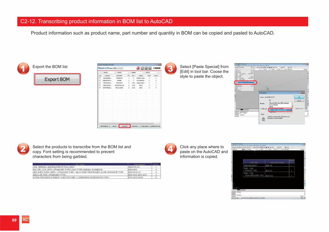
Select the products to transcribe from the BOM list and copy. Font setting is recommended to prevent characters from being garbled.
Export the BOM list Select [Paste Special] from [Edit] in tool bar. Coose the style to paste the object.
Click any place where to paste on the AutoCAD and information is copied.
C2-12. Transcribing product information in BOM list to AutoCAD
Product information such as product name, part number and quantity in BOM can be copied and pasted to AutoCAD.
11 33
4422
ACAC69
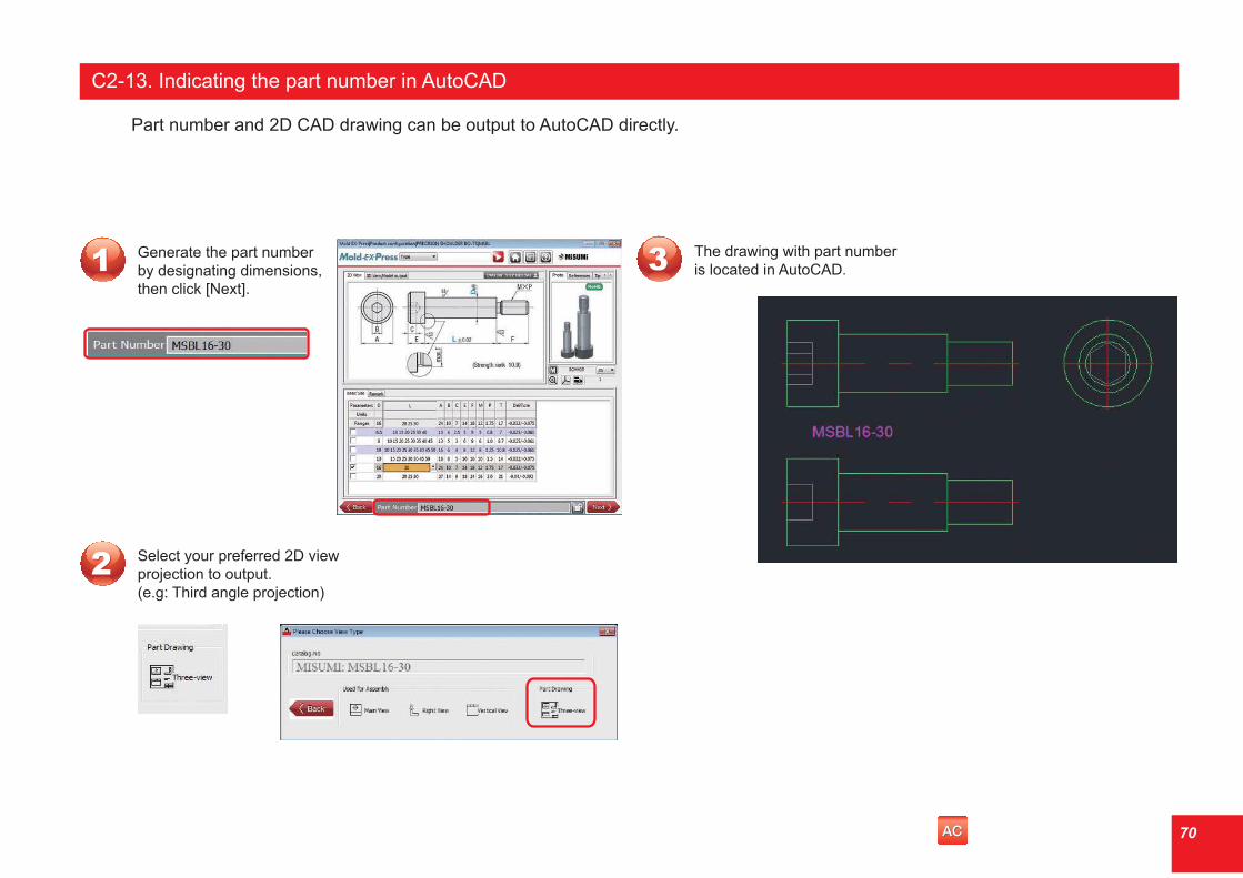
Select your preferred 2D view projection to output. (e.g: Third angle projection)
The drawing with part number is located in AutoCAD
C2-13. Indicating the part number in AutoCAD
Part number and 2D CAD drawing can be output to AutoCAD directly.
11 33
22
Generate the part number by designating dimensions, then click [Next].
ACAC 70

Right-click within the frame of 3D view, and choose [Left] from [View Mode].
The display of the model changes to the left side view.
The display also changes by clicking #5 View Direction of the Tool bar in 3D preview screen.
Each click of [View Direction] icon, the view changes sequentially by a following order;
Isometric→Top→Bottom→Front→Back→Left side→Right side
Click #4 Fit to position the part model instantly in the center of the window frame.
C2-14. Changing view direction of 3D part model and returning its position to the center
After changing view direction, you can return instantly to the standard position by the following operations.
11
33
44
5522
1. 2. 3. 4 . 5. 6.
1. 2. 3. 4 . 5. 6.
1 Wire Frame2 Shading3 Shading with Edges
4 Fit5 View Direction6 Help
1 Wire Frame2 Shading3 Shading with Edges
4 Fit5 View Direction6 Help
71

Right-click within the frame of 3D view, and choose the [Options].
Display any [3D View] window. Check the [Reverse Vertical Control] box, and click the OK button.
C2-15. Changing model scale with a mouse
Rotation direction of the mouse wheel by which the model expands or contracts differs depending on the CAD software. For example if the mouse wheel is rotated upwards, the model expands in Pro/E but contracts in CATIA. We recommend you to adjust as required to meet your usage habit.
11 33
22
72

At the time of CAD introduction, this basic location is referred to parts location.
C2-16. Apply Mold EX-Press standard parts location
11
22
After introduction, the display comes out as per right figure.
33Confirm the standard parts location in 3D preview.
The parts list in Mold EX-Press includes standard part location. You may select right parts by using this standard location data.
ACAC CACA CRCRNXNX P/EP/ESWSW73

Right-click within the frame of 3D view, and choose the [Options].
Display any [3D View] window. Select [Change Background Color] and choose the colors for the Top area and the Bottom area.
Background colors are adjusted accordingly.
C2-17. Changing the background color of the 3D preview
Background colors of the 3D preview can be adjusted according to your preference.
11 33
4422
74